Embed Size (px)
Citation preview

CHECKED BY:
DRAWN BY:
PROJECT NO:
SUBMITTALS
G R O U PTLANTIS
CTNL804B
AMTRAK_OLDLYME5
387 SHORE ROAD
OLD LYME, CT 06376
T-MOBILE NORTHEAST, LLC35 GRIFFIN ROAD SOUTHBLOOMFIELD, CT 06002OFFICE: (860) 692-7100
FAX:(860) 692-7159
T-MOBILE NORTHEAST LLC
CHECKED BY:
DRAWN BY:
PROJECT NO:
SUBMITTALS
G R O U PTLANTIS
CTNL804B
AMTRAK_OLDLYME5
387 SHORE ROAD
OLD LYME, CT 06376
T-MOBILE NORTHEAST, LLC35 GRIFFIN ROAD SOUTHBLOOMFIELD, CT 06002OFFICE: (860) 692-7100
FAX:(860) 692-7159
x
x
xxxxxxxxxxx
xx
xx
xx
x
x x x x x x x x x x x
xx
x
CHECKED BY:
DRAWN BY:
PROJECT NO:
SUBMITTALS
G R O U PTLANTIS
CTNL804B
AMTRAK_OLDLYME5
387 SHORE ROAD
OLD LYME, CT 06376
T-MOBILE NORTHEAST, LLC35 GRIFFIN ROAD SOUTHBLOOMFIELD, CT 06002OFFICE: (860) 692-7100
FAX:(860) 692-7159
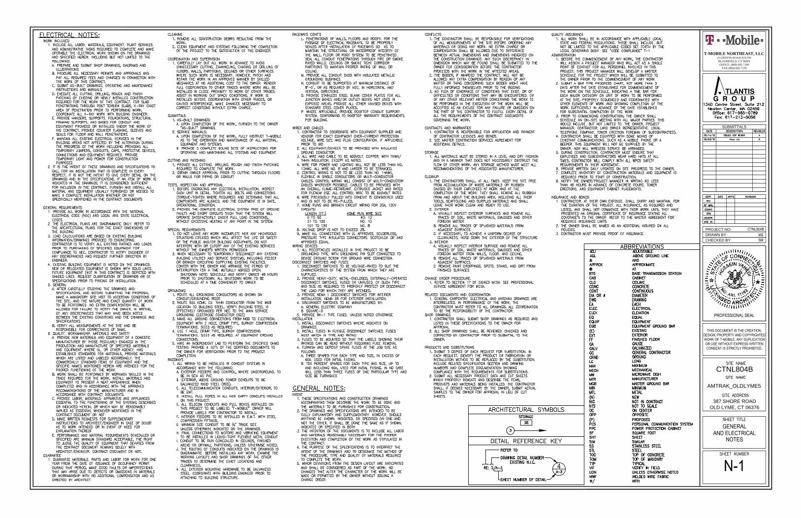
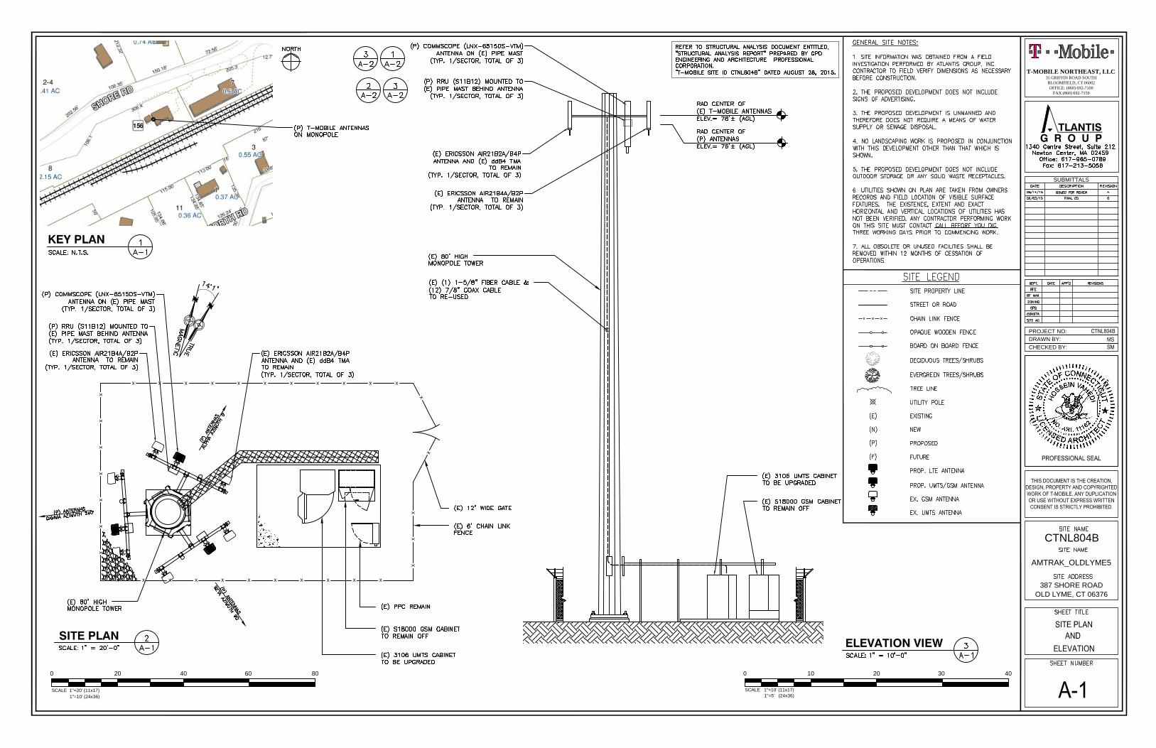
SITE PLAN ELEVATION VIEW
KEY PLAN
SCALE 1"=20' (11x17)
0 20 40 8060
1"=10' (24x36)
SCALE 1"=10' (11x17)
0 10 20 4030
1"=5' (24x36)
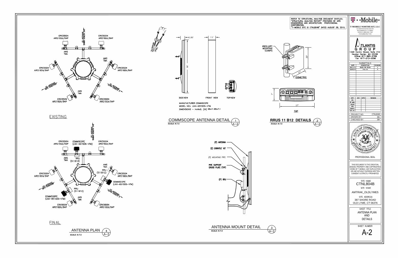
ANTENNA PLAN
SCALE: N.T.S
CHECKED BY:
DRAWN BY:
PROJECT NO:
SUBMITTALS
G R O U PTLANTIS
CTNL804B
AMTRAK_OLDLYME5
387 SHORE ROAD
OLD LYME, CT 06376
T-MOBILE NORTHEAST, LLC35 GRIFFIN ROAD SOUTHBLOOMFIELD, CT 06002OFFICE: (860) 692-7100
FAX:(860) 692-7159
RRUS 11 B12 DETAILSSCALE: N.T.S
17"
7"
1
7
"
20
"
COMMSCOPE ANTENNA DETAIL
SCALE: N.T.S
11.85"
96"
7.1"
ANTENNA MOUNT DETAIL
SCALE: N.T.S
CHECKED BY:
DRAWN BY:
PROJECT NO:
SUBMITTALS
G R O U PTLANTIS
CTNL804B
AMTRAK_OLDLYME5
387 SHORE ROAD
OLD LYME, CT 06376
T-MOBILE NORTHEAST, LLC35 GRIFFIN ROAD SOUTHBLOOMFIELD, CT 06002OFFICE: (860) 692-7100
FAX:(860) 692-7159
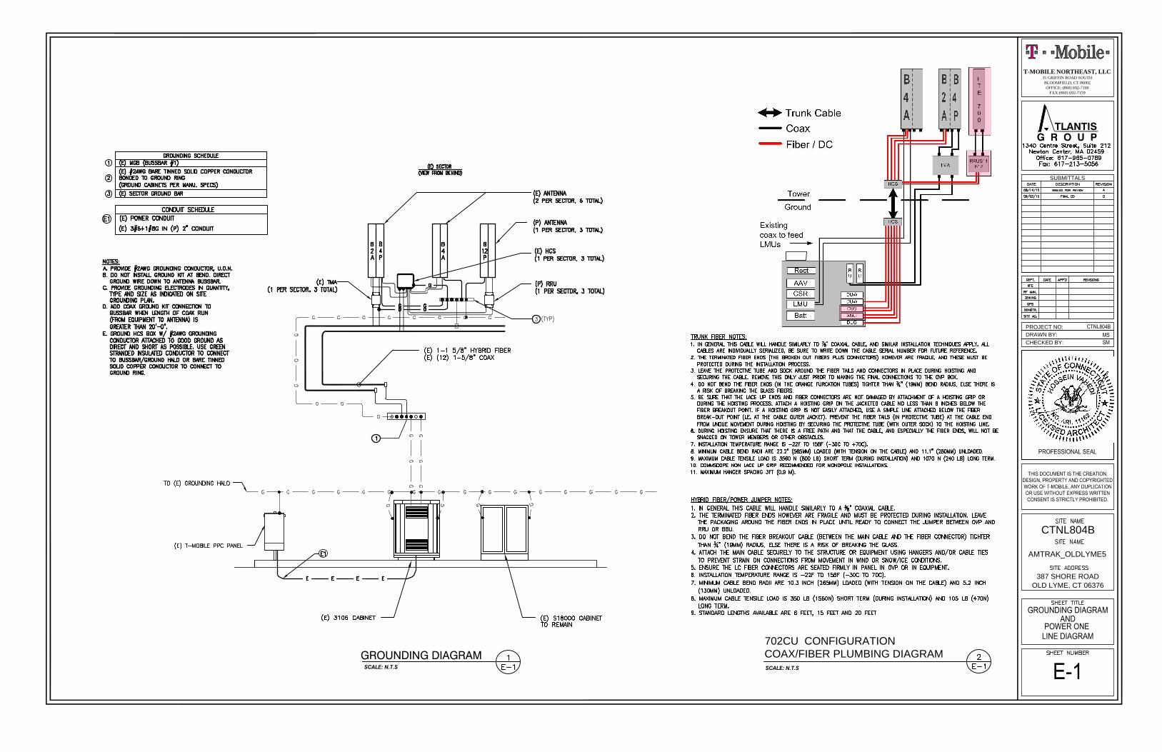
702CU CONFIGURATION
SCALE: N.T.S
COAX/FIBER PLUMBING DIAGRAMGROUNDING DIAGRAMSCALE: N.T.S
CHECKED BY:
DRAWN BY:
PROJECT NO:
SUBMITTALS
G R O U PTLANTIS
CTNL804B
AMTRAK_OLDLYME5
387 SHORE ROAD
OLD LYME, CT 06376
T-MOBILE NORTHEAST, LLC35 GRIFFIN ROAD SOUTHBLOOMFIELD, CT 06002OFFICE: (860) 692-7100
FAX:(860) 692-7159
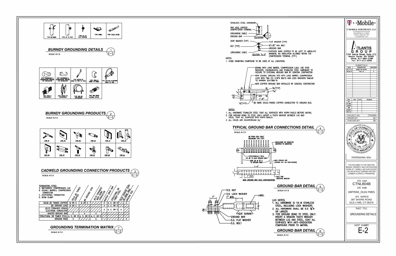
GROUND BAR DETAILSCALE: N.T.S
BURNDY GROUNDING PRODUCTSSCALE: N.T.S
CADWELD GROUNDING CONNECTION PRODUCTSSCALE: N.T.S
GROUNDING TERMINATION MATRIXSCALE: N.T.S
TYPICAL GROUND BAR CONNECTIONS DETAILSCALE: N.T.S
GROUND BAR DETAILSCALE: N.T.S
BURNDY GROUNDING DETAILSSCALE: N.T.S
520 South Main Street . Suite 2531 . Akron, Ohio 44311 . 330-572-2100 . Fax 330-572-2101 . www.GPDGroup.com GPD Engineering And Architecture Professional Corporation
T-Mobile Towers Chris Scheks 12920 SE 38th Street 520 South Main Street, Suite 2531 Bellevue, WA 98006 Akron, OH 44311 (425) 383-3978 (614) 588-8973 [email protected]
GPD# 2015791.16
August 28, 2015
STRUCTURAL ANALYSIS REPORT
T-MOBILE DESIGNATION: Site Number:
Site Name: T-Mobile Project:
CTNL804B AMTRAK_OldLyme5 Network Modification
ANALYSIS CRITERIA: Codes: TIA/EIA-222-F, 2003 IBC & 2005 CTBC
104-mph fastest-mile (equivalent 120mph 3 second gust) with 0" ice 38-mph fastest-mile (equivalent 50mph 3 second gust) with 0.75" ice
SITE DATA: 387 Shore Road, Old Lyme, CT 06371, New London County
Latitude 41° 17' 47.36" N, Longitude 72° 15' 34.89" W 80' Sabre Monopole
Mr. John Warzecha, GPD is pleased to submit this Structural Analysis Report to determine the structural integrity of the aforementioned
tower. The purpose of the analysis is to determine the suitability of the tower with the existing and proposed loading
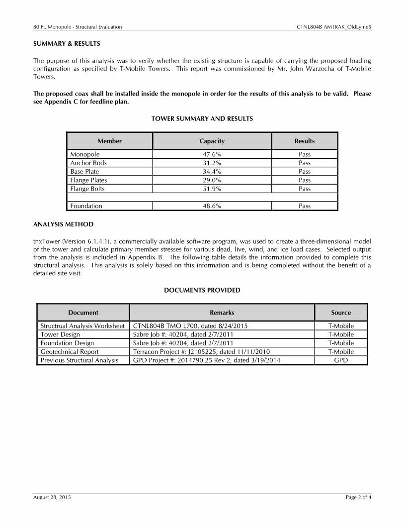
configuration detailed in the analysis report. Analysis Results Tower Stress Level with Proposed Equipment: 51.9% Pass Foundation Ratio with Proposed Equipment: 48.6% Pass We at GPD appreciate the opportunity of providing our continuing professional services to you and T-Mobile Towers.
If you have any questions or need further assistance on this or any other projects please do not hesitate to call. Respectfully submitted,
Christopher J. Scheks, P.E. Connecticut #: 0030026
80 Ft. Monopole - Structural Evaluation CTNL804B AMTRAK_OldLyme5
August 28, 2015 Page 2 of 4
SUMMARY & RESULTS The purpose of this analysis was to verify whether the existing structure is capable of carrying the proposed loading
configuration as specified by T-Mobile Towers. This report was commissioned by Mr. John Warzecha of T-Mobile
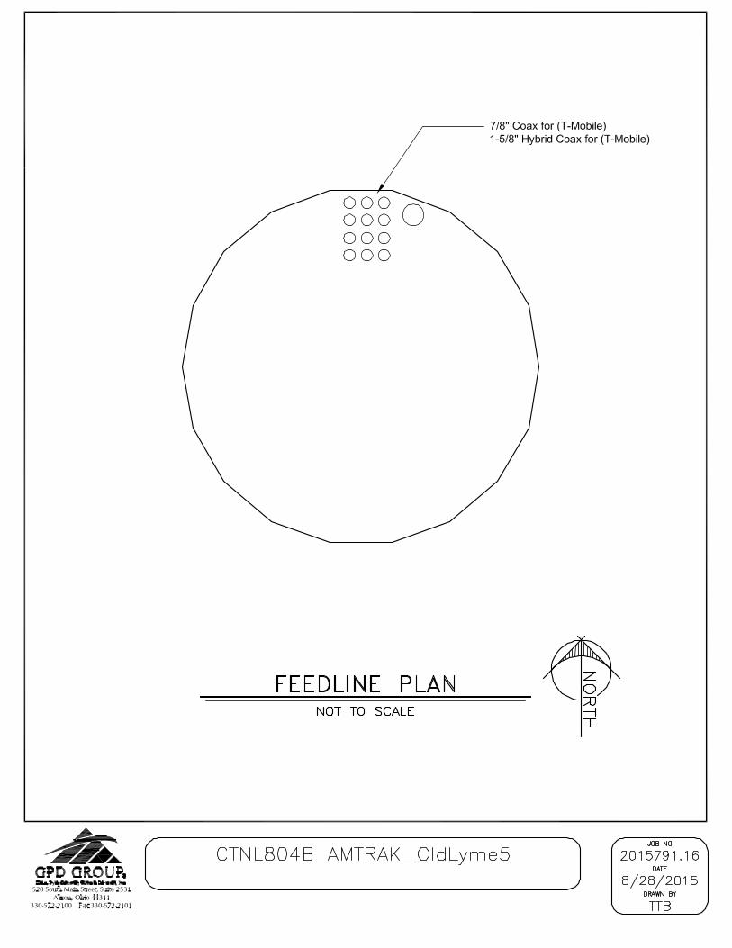
Towers. The proposed coax shall be installed inside the monopole in order for the results of this analysis to be valid. Please
see Appendix C for feedline plan.
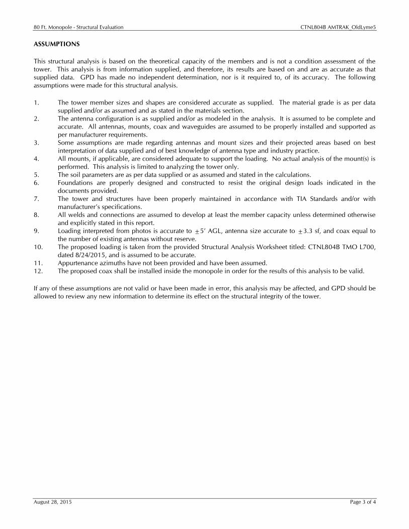
TOWER SUMMARY AND RESULTS
Member Capacity Results
Monopole 47.6% Pass Anchor Rods 31.2% Pass Base Plate 34.4% Pass Flange Plates 29.0% Pass Flange Bolts 51.9% Pass
Foundation 48.6% Pass
ANALYSIS METHOD tnxTower (Version 6.1.4.1), a commercially available software program, was used to create a three-dimensional model
of the tower and calculate primary member stresses for various dead, live, wind, and ice load cases. Selected output
from the analysis is included in Appendix B. The following table details the information provided to complete this
structural analysis. This analysis is solely based on this information and is being completed without the benefit of a
detailed site visit.
DOCUMENTS PROVIDED
Document Remarks Source
Structrual Analysis Worksheet CTNL804B TMO L700, dated 8/24/2015 T-Mobile Tower Design Sabre Job #: 40204, dated 2/7/2011 T-Mobile Foundation Design Sabre Job #: 40204, dated 2/7/2011 T-Mobile Geotechnical Report Terracon Project #: J2105225, dated 11/11/2010 T-Mobile Previous Structural Analysis GPD Project #: 2014790.25 Rev 2, dated 3/19/2014 GPD
80 Ft. Monopole - Structural Evaluation CTNL804B AMTRAK_OldLyme5
August 28, 2015 Page 3 of 4
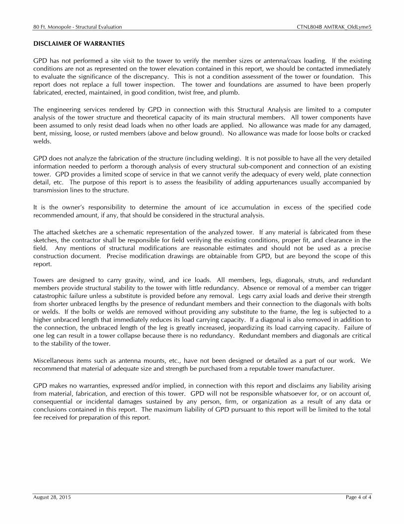
ASSUMPTIONS This structural analysis is based on the theoretical capacity of the members and is not a condition assessment of the
tower. This analysis is from information supplied, and therefore, its results are based on and are as accurate as that
supplied data. GPD has made no independent determination, nor is it required to, of its accuracy. The following
assumptions were made for this structural analysis. 1. The tower member sizes and shapes are considered accurate as supplied. The material grade is as per data
supplied and/or as assumed and as stated in the materials section. 2. The antenna configuration is as supplied and/or as modeled in the analysis. It is assumed to be complete and
accurate. All antennas, mounts, coax and waveguides are assumed to be properly installed and supported as
per manufacturer requirements. 3. Some assumptions are made regarding antennas and mount sizes and their projected areas based on best
interpretation of data supplied and of best knowledge of antenna type and industry practice. 4. All mounts, if applicable, are considered adequate to support the loading. No actual analysis of the mount(s) is
performed. This analysis is limited to analyzing the tower only. 5. The soil parameters are as per data supplied or as assumed and stated in the calculations. 6. Foundations are properly designed and constructed to resist the original design loads indicated in the
documents provided. 7. The tower and structures have been properly maintained in accordance with TIA Standards and/or with
manufacturer’s specifications. 8. All welds and connections are assumed to develop at least the member capacity unless determined otherwise
and explicitly stated in this report. 9. Loading interpreted from photos is accurate to ±5’ AGL, antenna size accurate to ±3.3 sf, and coax equal to
the number of existing antennas without reserve.
10. The proposed loading is taken from the provided Structural Analysis Worksheet titled: CTNL804B TMO L700,
dated 8/24/2015, and is assumed to be accurate.
11. Appurtenance azimuths have not been provided and have been assumed.
12. The proposed coax shall be installed inside the monopole in order for the results of this analysis to be valid.
If any of these assumptions are not valid or have been made in error, this analysis may be affected, and GPD should be
allowed to review any new information to determine its effect on the structural integrity of the tower.
80 Ft. Monopole - Structural Evaluation CTNL804B AMTRAK_OldLyme5
August 28, 2015 Page 4 of 4
DISCLAIMER OF WARRANTIES GPD has not performed a site visit to the tower to verify the member sizes or antenna/coax loading. If the existing
conditions are not as represented on the tower elevation contained in this report, we should be contacted immediately
to evaluate the significance of the discrepancy. This is not a condition assessment of the tower or foundation. This
report does not replace a full tower inspection. The tower and foundations are assumed to have been properly
fabricated, erected, maintained, in good condition, twist free, and plumb. The engineering services rendered by GPD in connection with this Structural Analysis are limited to a computer
analysis of the tower structure and theoretical capacity of its main structural members. All tower components have
been assumed to only resist dead loads when no other loads are applied. No allowance was made for any damaged,
bent, missing, loose, or rusted members (above and below ground). No allowance was made for loose bolts or cracked
welds. GPD does not analyze the fabrication of the structure (including welding). It is not possible to have all the very detailed
information needed to perform a thorough analysis of every structural sub-component and connection of an existing
tower. GPD provides a limited scope of service in that we cannot verify the adequacy of every weld, plate connection
detail, etc. The purpose of this report is to assess the feasibility of adding appurtenances usually accompanied by
transmission lines to the structure. It is the owner’s responsibility to determine the amount of ice accumulation in excess of the specified code
recommended amount, if any, that should be considered in the structural analysis. The attached sketches are a schematic representation of the analyzed tower. If any material is fabricated from these
sketches, the contractor shall be responsible for field verifying the existing conditions, proper fit, and clearance in the
field. Any mentions of structural modifications are reasonable estimates and should not be used as a precise
construction document. Precise modification drawings are obtainable from GPD, but are beyond the scope of this
report.
Towers are designed to carry gravity, wind, and ice loads. All members, legs, diagonals, struts, and redundant
members provide structural stability to the tower with little redundancy. Absence or removal of a member can trigger
catastrophic failure unless a substitute is provided before any removal. Legs carry axial loads and derive their strength
from shorter unbraced lengths by the presence of redundant members and their connection to the diagonals with bolts
or welds. If the bolts or welds are removed without providing any substitute to the frame, the leg is subjected to a
higher unbraced length that immediately reduces its load carrying capacity. If a diagonal is also removed in addition to
the connection, the unbraced length of the leg is greatly increased, jeopardizing its load carrying capacity. Failure of
one leg can result in a tower collapse because there is no redundancy. Redundant members and diagonals are critical
to the stability of the tower.
Miscellaneous items such as antenna mounts, etc., have not been designed or detailed as a part of our work. We
recommend that material of adequate size and strength be purchased from a reputable tower manufacturer. GPD makes no warranties, expressed and/or implied, in connection with this report and disclaims any liability arising
from material, fabrication, and erection of this tower. GPD will not be responsible whatsoever for, or on account of,
consequential or incidental damages sustained by any person, firm, or organization as a result of any data or
conclusions contained in this report. The maximum liability of GPD pursuant to this report will be limited to the total
fee received for preparation of this report.
80 Ft. Monopole - Structural Evaluation CTNL804B AMTRAK_OldLyme5
August 28, 2015
APPENDIX A
Tower Analysis Summary Form
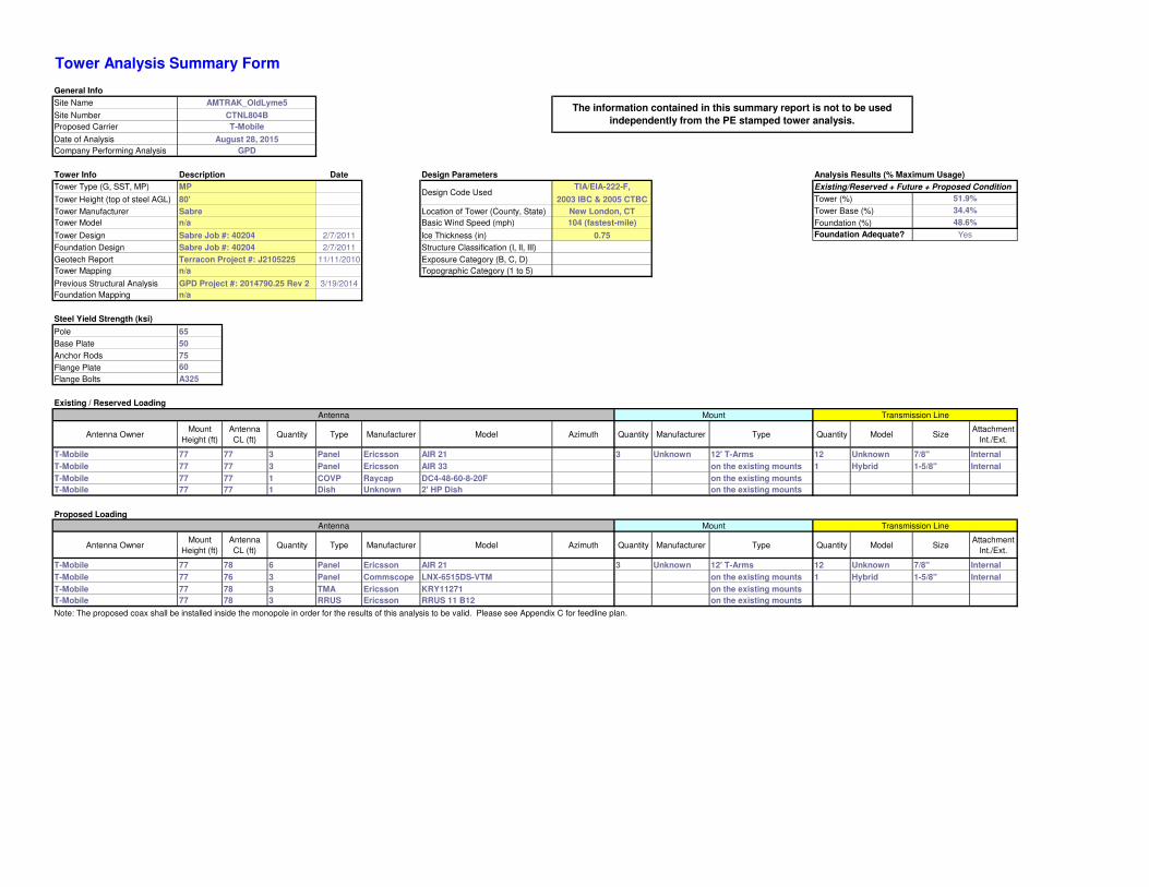
Tower Analysis Summary Form
General Info
Site Name AMTRAK_OldLyme5
Site Number CTNL804B
Proposed Carrier T-Mobile
Date of Analysis August 28, 2015
Company Performing Analysis GPD
Tower Info Description Date Design Parameters Analysis Results (% Maximum Usage)
Tower Type (G, SST, MP) Existing/Reserved + Future + Proposed Condition
Tower Height (top of steel AGL) Tower (%)
Tower Manufacturer Location of Tower (County, State) Tower Base (%)
Tower Model Basic Wind Speed (mph) Foundation (%)
Tower Design 2/7/2011 Ice Thickness (in)
Foundation Design 2/7/2011 Structure Classification (I, II, III)
Geotech Report 11/11/2010 Exposure Category (B, C, D)
Tower Mapping Topographic Category (1 to 5)
Previous Structural Analysis 3/19/2014
Foundation Mapping
Steel Yield Strength (ksi)
Pole 65
Base Plate 50
Anchor Rods 75
Flange Plate 60
Flange Bolts A325
Existing / Reserved Loading
Antenna Mount Transmission Line
Antenna OwnerMount
Height (ft)
Antenna
CL (ft)Quantity Type Manufacturer Model Azimuth Quantity Manufacturer Type Quantity Model Size
Attachment
Int./Ext.
T-Mobile 77 77 3 Panel Ericsson AIR 21 3 Unknown 12' T-Arms 12 Unknown 7/8" Internal
T-Mobile 77 77 3 Panel Ericsson AIR 33 on the existing mounts 1 Hybrid 1-5/8" Internal
T-Mobile 77 77 1 COVP Raycap DC4-48-60-8-20F on the existing mounts
T-Mobile 77 77 1 Dish Unknown 2' HP Dish on the existing mounts
Proposed Loading
Antenna Mount Transmission Line
Antenna OwnerMount
Height (ft)
Antenna
CL (ft)Quantity Type Manufacturer Model Azimuth Quantity Manufacturer Type Quantity Model Size
Attachment
Int./Ext.
T-Mobile 77 78 6 Panel Ericsson AIR 21 3 Unknown 12' T-Arms 12 Unknown 7/8" Internal
T-Mobile 77 76 3 Panel Commscope LNX-6515DS-VTM on the existing mounts 1 Hybrid 1-5/8" Internal
T-Mobile 77 78 3 TMA Ericsson KRY11271 on the existing mounts
T-Mobile 77 78 3 RRUS Ericsson RRUS 11 B12 on the existing mounts
Note: The proposed coax shall be installed inside the monopole in order for the results of this analysis to be valid. Please see Appendix C for feedline plan.
Foundation Adequate?
MP
80'
Sabre
n/a
Sabre Job #: 40204
Sabre Job #: 40204
Terracon Project #: J2105225
n/a
GPD Project #: 2014790.25 Rev 2
n/a
51.9%
34.4%
104 (fastest-mile)
0.75 Yes
48.6%
The information contained in this summary report is not to be used
independently from the PE stamped tower analysis.
Design Code UsedTIA/EIA-222-F,
2003 IBC & 2005 CTBC
New London, CT

80 Ft. Monopole - Structural Evaluation CTNL804B AMTRAK_OldLyme5
August 28, 2015
APPENDIX B
tnxTower Output File
ttnnxxTToowweerr Job
CTNL804B AMTRAK _ OldLyme5
Page
1 of 4
GPD
520 South Main Street, Suite 2531
Project
2015791.16
Date
08:19:12 08/28/15
Akron, OH 44311
Phone: (330) 572-2100
FAX: (330) 572-3709
Client
T-Mobile Towers Designed by
tbeltz
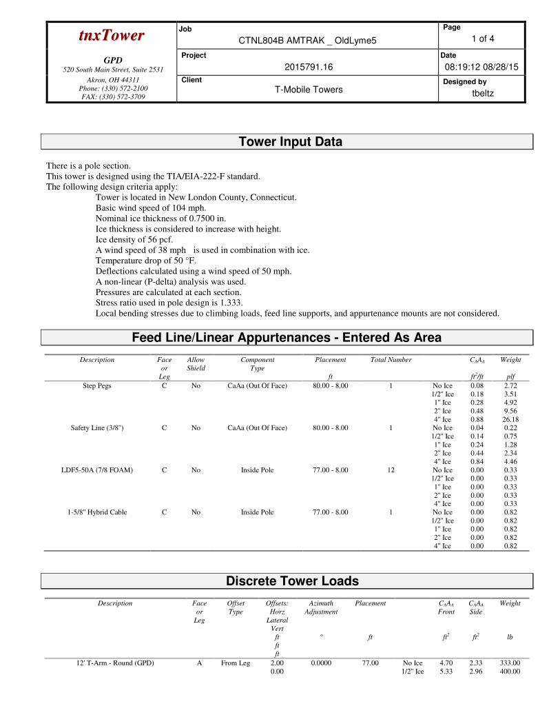
Tower Input Data
There is a pole section.
This tower is designed using the TIA/EIA-222-F standard.
The following design criteria apply:
Tower is located in New London County, Connecticut.
Basic wind speed of 104 mph.
Nominal ice thickness of 0.7500 in.
Ice thickness is considered to increase with height.
Ice density of 56 pcf.
A wind speed of 38 mph is used in combination with ice.
Temperature drop of 50 °F.
Deflections calculated using a wind speed of 50 mph.
A non-linear (P-delta) analysis was used.
Pressures are calculated at each section.
Stress ratio used in pole design is 1.333.
Local bending stresses due to climbing loads, feed line supports, and appurtenance mounts are not considered.
Feed Line/Linear Appurtenances - Entered As Area
Description Face
or
Leg
Allow
Shield
Component
Type
Placement
ft
Total Number CAAA
ft2/ft
Weight
plf
Step Pegs C No CaAa (Out Of Face) 80.00 - 8.00 1 No Ice
1/2'' Ice
1'' Ice
2'' Ice
4'' Ice
0.08
0.18
0.28
0.48
0.88
2.72
3.51
4.92
9.56
26.18
Safety Line (3/8'') C No CaAa (Out Of Face) 80.00 - 8.00 1 No Ice
1/2'' Ice
1'' Ice
2'' Ice
4'' Ice
0.04
0.14
0.24
0.44
0.84
0.22
0.75
1.28
2.34
4.46
LDF5-50A (7/8 FOAM) C No Inside Pole 77.00 - 8.00 12 No Ice
1/2'' Ice
1'' Ice
2'' Ice
4'' Ice
0.00
0.00
0.00
0.00
0.00
0.33
0.33
0.33
0.33
0.33
1-5/8'' Hybrid Cable C No Inside Pole 77.00 - 8.00 1 No Ice
1/2'' Ice
1'' Ice
2'' Ice
4'' Ice
0.00
0.00
0.00
0.00
0.00
0.82
0.82
0.82
0.82
0.82
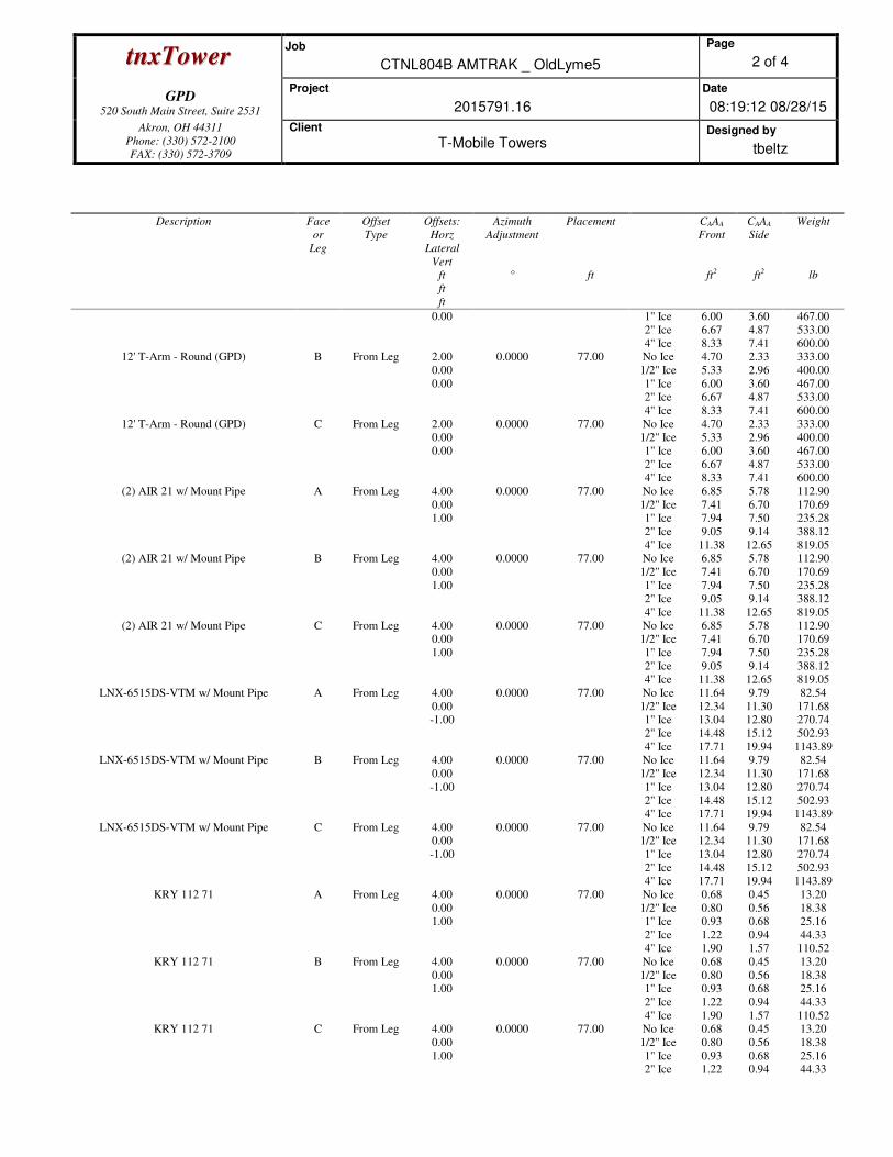
Discrete Tower Loads
Description Face
or
Leg
Offset
Type
Offsets:
Horz
Lateral
Vert
ft
ft
ft
Azimuth
Adjustment
°
Placement
ft
CAAA
Front
ft2
CAAA
Side
ft2
Weight
lb
12' T-Arm - Round (GPD) A From Leg 2.00
0.00
0.0000 77.00 No Ice
1/2'' Ice
4.70
5.33
2.33
2.96
333.00
400.00
ttnnxxTToowweerr Job
CTNL804B AMTRAK _ OldLyme5
Page
2 of 4
GPD
520 South Main Street, Suite 2531
Project
2015791.16
Date
08:19:12 08/28/15
Akron, OH 44311
Phone: (330) 572-2100
FAX: (330) 572-3709
Client
T-Mobile Towers Designed by
tbeltz
Description Face
or
Leg
Offset
Type
Offsets:
Horz
Lateral
Vert
ft
ft
ft
Azimuth
Adjustment
°
Placement
ft
CAAA
Front
ft2
CAAA
Side
ft2
Weight
lb
0.00 1'' Ice
2'' Ice
4'' Ice
6.00
6.67
8.33
3.60
4.87
7.41
467.00
533.00
600.00
12' T-Arm - Round (GPD) B From Leg 2.00
0.00
0.00
0.0000 77.00 No Ice
1/2'' Ice
1'' Ice
2'' Ice
4'' Ice
4.70
5.33
6.00
6.67
8.33
2.33
2.96
3.60
4.87
7.41
333.00
400.00
467.00
533.00
600.00
12' T-Arm - Round (GPD) C From Leg 2.00
0.00
0.00
0.0000 77.00 No Ice
1/2'' Ice
1'' Ice
2'' Ice
4'' Ice
4.70
5.33
6.00
6.67
8.33
2.33
2.96
3.60
4.87
7.41
333.00
400.00
467.00
533.00
600.00
(2) AIR 21 w/ Mount Pipe A From Leg 4.00
0.00
1.00
0.0000 77.00 No Ice
1/2'' Ice
1'' Ice
2'' Ice
4'' Ice
6.85
7.41
7.94
9.05
11.38
5.78
6.70
7.50
9.14
12.65
112.90
170.69
235.28
388.12
819.05
(2) AIR 21 w/ Mount Pipe B From Leg 4.00
0.00
1.00
0.0000 77.00 No Ice
1/2'' Ice
1'' Ice
2'' Ice
4'' Ice
6.85
7.41
7.94
9.05
11.38
5.78
6.70
7.50
9.14
12.65
112.90
170.69
235.28
388.12
819.05
(2) AIR 21 w/ Mount Pipe C From Leg 4.00
0.00
1.00
0.0000 77.00 No Ice
1/2'' Ice
1'' Ice
2'' Ice
4'' Ice
6.85
7.41
7.94
9.05
11.38
5.78
6.70
7.50
9.14
12.65
112.90
170.69
235.28
388.12
819.05
LNX-6515DS-VTM w/ Mount Pipe A From Leg 4.00
0.00
-1.00
0.0000 77.00 No Ice
1/2'' Ice
1'' Ice
2'' Ice
4'' Ice
11.64
12.34
13.04
14.48
17.71
9.79
11.30
12.80
15.12
19.94
82.54
171.68
270.74
502.93
1143.89
LNX-6515DS-VTM w/ Mount Pipe B From Leg 4.00
0.00
-1.00
0.0000 77.00 No Ice
1/2'' Ice
1'' Ice
2'' Ice
4'' Ice
11.64
12.34
13.04
14.48
17.71
9.79
11.30
12.80
15.12
19.94
82.54
171.68
270.74
502.93
1143.89
LNX-6515DS-VTM w/ Mount Pipe C From Leg 4.00
0.00
-1.00
0.0000 77.00 No Ice
1/2'' Ice
1'' Ice
2'' Ice
4'' Ice
11.64
12.34
13.04
14.48
17.71
9.79
11.30
12.80
15.12
19.94
82.54
171.68
270.74
502.93
1143.89
KRY 112 71 A From Leg 4.00
0.00
1.00
0.0000 77.00 No Ice
1/2'' Ice
1'' Ice
2'' Ice
4'' Ice
0.68
0.80
0.93
1.22
1.90
0.45
0.56
0.68
0.94
1.57
13.20
18.38
25.16
44.33
110.52
KRY 112 71 B From Leg 4.00
0.00
1.00
0.0000 77.00 No Ice
1/2'' Ice
1'' Ice
2'' Ice
4'' Ice
0.68
0.80
0.93
1.22
1.90
0.45
0.56
0.68
0.94
1.57
13.20
18.38
25.16
44.33
110.52
KRY 112 71 C From Leg 4.00
0.00
1.00
0.0000 77.00 No Ice
1/2'' Ice
1'' Ice
2'' Ice
0.68
0.80
0.93
1.22
0.45
0.56
0.68
0.94
13.20
18.38
25.16
44.33
ttnnxxTToowweerr Job
CTNL804B AMTRAK _ OldLyme5
Page
3 of 4
GPD
520 South Main Street, Suite 2531
Project
2015791.16
Date
08:19:12 08/28/15
Akron, OH 44311
Phone: (330) 572-2100
FAX: (330) 572-3709
Client
T-Mobile Towers Designed by
tbeltz
Description Face
or
Leg
Offset
Type
Offsets:
Horz
Lateral
Vert
ft
ft
ft
Azimuth
Adjustment
°
Placement
ft
CAAA
Front
ft2
CAAA
Side
ft2
Weight
lb
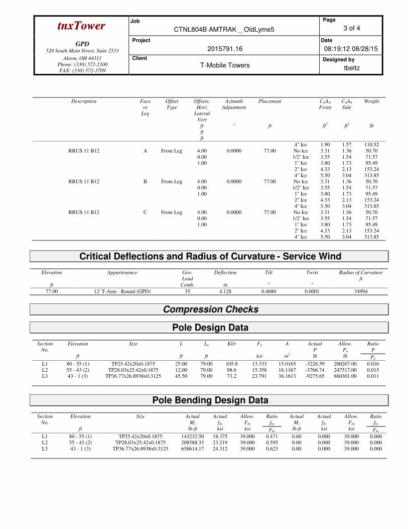
4'' Ice 1.90 1.57 110.52
RRUS 11 B12 A From Leg 4.00
0.00
1.00
0.0000 77.00 No Ice
1/2'' Ice
1'' Ice
2'' Ice
4'' Ice
3.31
3.55
3.80
4.33
5.50
1.36
1.54
1.73
2.13
3.04
50.70
71.57
95.49
153.24
313.85
RRUS 11 B12 B From Leg 4.00
0.00
1.00
0.0000 77.00 No Ice
1/2'' Ice
1'' Ice
2'' Ice
4'' Ice
3.31
3.55
3.80
4.33
5.50
1.36
1.54
1.73
2.13
3.04
50.70
71.57
95.49
153.24
313.85
RRUS 11 B12 C From Leg 4.00
0.00
1.00
0.0000 77.00 No Ice
1/2'' Ice
1'' Ice
2'' Ice
4'' Ice
3.31
3.55
3.80
4.33
5.50
1.36
1.54
1.73
2.13
3.04
50.70
71.57
95.49
153.24
313.85
Critical Deflections and Radius of Curvature - Service Wind
Elevation
ft
Appurtenance Gov.
Load
Comb.
Deflection
in
Tilt
°
Twist
°
Radius of Curvature
ft
77.00 12' T-Arm - Round (GPD) 35 4.128 0.4680 0.0001 34994
Compression Checks
Pole Design Data
Section
No.
Elevation
ft
Size
L
ft
Lu
ft
Kl/r
Fa
ksi
A
in2
Actual
P
lb
Allow.
Pa
lb
Ratio
P
Pa
L1 80 - 55 (1) TP25.42x20x0.1875 25.00 79.00 105.8 13.333 15.0165 -3226.59 200207.00 0.016
L2 55 - 43 (2) TP28.03x25.42x0.1875 12.00 79.00 98.6 15.358 16.1167 -3766.74 247517.00 0.015
L3 43 - 1 (3) TP36.77x26.8938x0.3125 45.50 79.00 73.2 23.791 36.1613 -9275.65 860301.00 0.011
Pole Bending Design Data
Section
No.
Elevation
ft
Size
Actual
Mx
lb-ft
Actual
fbx
ksi
Allow.
Fbx
ksi
Ratio
fbx
Fbx
Actual
My
lb-ft
Actual
fby
ksi
Allow.
Fby
ksi
Ratio
fby
Fby
L1 80 - 55 (1) TP25.42x20x0.1875 143232.50 18.375 39.000 0.471 0.00 0.000 39.000 0.000
L2 55 - 43 (2) TP28.03x25.42x0.1875 208588.33 23.219 39.000 0.595 0.00 0.000 39.000 0.000
L3 43 - 1 (3) TP36.77x26.8938x0.3125 658614.17 24.312 39.000 0.623 0.00 0.000 39.000 0.000
ttnnxxTToowweerr Job
CTNL804B AMTRAK _ OldLyme5
Page
4 of 4
GPD
520 South Main Street, Suite 2531
Project
2015791.16
Date
08:19:12 08/28/15
Akron, OH 44311
Phone: (330) 572-2100
FAX: (330) 572-3709
Client
T-Mobile Towers Designed by
tbeltz
Pole Shear Design Data
Section
No.
Elevation
ft
Size
Actual
V
lb
Actual
fv
ksi
Allow.
Fv
ksi
Ratio
fv
Fv
Actual
T
lb-ft
Actual
fvt
ksi
Allow.
Fvt
ksi
Ratio
fvt
Fvt
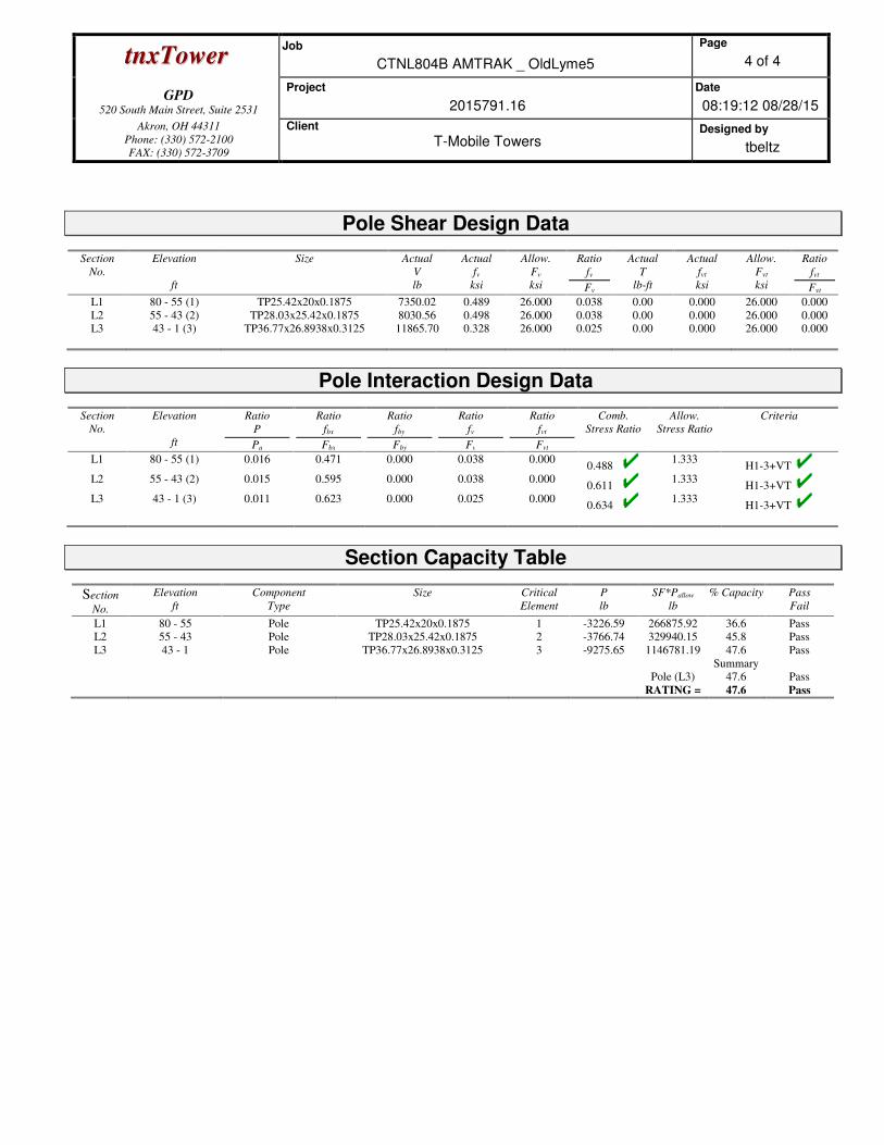
L1 80 - 55 (1) TP25.42x20x0.1875 7350.02 0.489 26.000 0.038 0.00 0.000 26.000 0.000
L2 55 - 43 (2) TP28.03x25.42x0.1875 8030.56 0.498 26.000 0.038 0.00 0.000 26.000 0.000
L3 43 - 1 (3) TP36.77x26.8938x0.3125 11865.70 0.328 26.000 0.025 0.00 0.000 26.000 0.000
Pole Interaction Design Data
Section
No.
Elevation
ft
Ratio
P
Pa
Ratio
fbx
Fbx
Ratio
fby
Fby
Ratio
fv
Fv
Ratio
fvt
Fvt
Comb.
Stress Ratio
Allow.
Stress Ratio
Criteria
L1 80 - 55 (1) 0.016 0.471 0.000 0.038 0.000 0.488
1.333 H1-3+VT
L2 55 - 43 (2) 0.015 0.595 0.000 0.038 0.000 0.611
1.333 H1-3+VT
L3 43 - 1 (3) 0.011 0.623 0.000 0.025 0.000 0.634
1.333 H1-3+VT
Section Capacity Table
Section
No.
Elevation
ft
Component
Type
Size Critical
Element
P
lb
SF*Pallow
lb
% Capacity Pass
Fail
L1 80 - 55 Pole TP25.42x20x0.1875 1 -3226.59 266875.92 36.6 Pass
L2 55 - 43 Pole TP28.03x25.42x0.1875 2 -3766.74 329940.15 45.8 Pass
L3 43 - 1 Pole TP36.77x26.8938x0.3125 3 -9275.65 1146781.19 47.6 Pass
Summary
Pole (L3) 47.6 Pass
RATING = 47.6 Pass

80 Ft. Monopole - Structural Evaluation CTNL804B AMTRAK_OldLyme5
August 28, 2015
APPENDIX C
Tower Elevation Drawing
Consulting Engineers
GPD
520 South Main Street, Suite 2531
Akron, OH 44311 Phone: (330) 572-2100
FAX: (330) 572-3709
Job: CTNL804B AMTRAK _ OldLyme5
Project: 2015791.16 Client: T-Mobile Towers Drawn by: tbeltz App'd:
Code: TIA/EIA-222-F Date: 08/28/15 Scale: NTS Path:
\\AKRN05.gpdco.com\TELECOM\TMT\CTNL804B\02 2015791 16\tnx\CTNL804B.eri Dwg No. E-1
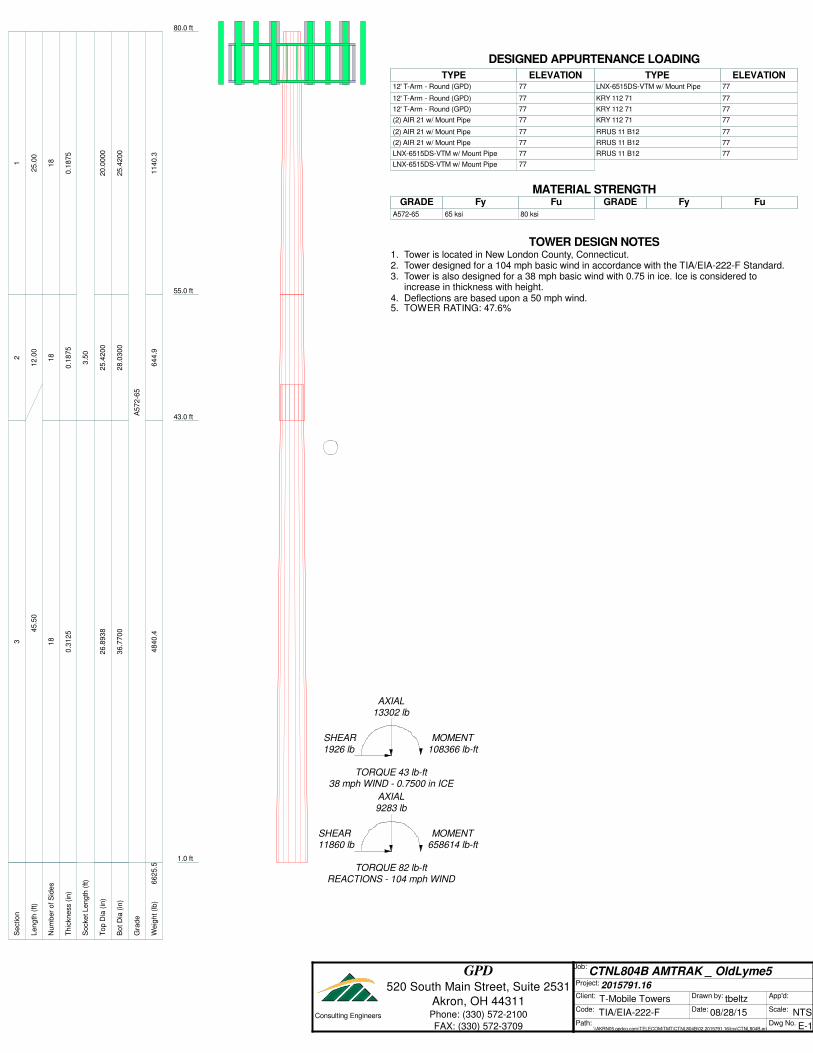
80.0 ft
55.0 ft
43.0 ft
1.0 ft
REACTIONS - 104 mph WINDTORQUE 82 lb-ft
11860 lbSHEAR
658614 lb-ftMOMENT
9283 lb
AXIAL
38 mph WIND - 0.7500 in ICETORQUE 43 lb-ft
1926 lb
SHEAR
108366 lb-ft
MOMENT
13302 lbAXIAL
S
ectio
n1
23
L
en
gth
(ft)
25
.00
12
.00
45
.50
N
um
be
r o
f S
ide
s1
81
81
8
T
hic
kn
ess (
in)
0.1
87
50
.18
75
0.3
12
5
S
ocke
t L
en
gth
(ft)
3.5
0
T
op
Dia
(in
)2
0.0
00
02
5.4
20
02
6.8
93
8
B
ot D
ia (
in)
25
.42
00
28
.03
00
36
.77
00
G
rad
eA
57
2-6
5
W
eig
ht (l
b)
11
40
.36
44
.94
84
0.4
66
25
.5
12' T-Arm - Round (GPD) 77 12' T-Arm - Round (GPD) 77 12' T-Arm - Round (GPD) 77 (2) AIR 21 w/ Mount Pipe 77 (2) AIR 21 w/ Mount Pipe 77 (2) AIR 21 w/ Mount Pipe 77 LNX-6515DS-VTM w/ Mount Pipe 77 LNX-6515DS-VTM w/ Mount Pipe 77 LNX-6515DS-VTM w/ Mount Pipe 77 KRY 112 71 77 KRY 112 71 77 KRY 112 71 77 RRUS 11 B12 77 RRUS 11 B12 77 RRUS 11 B12 77DESIGNED APPURTENANCE LOADING
TYPE TYPEELEVATION ELEVATION 12' T-Arm - Round (GPD) 77
12' T-Arm - Round (GPD) 77
12' T-Arm - Round (GPD) 77
(2) AIR 21 w/ Mount Pipe 77
(2) AIR 21 w/ Mount Pipe 77
(2) AIR 21 w/ Mount Pipe 77
LNX-6515DS-VTM w/ Mount Pipe 77
LNX-6515DS-VTM w/ Mount Pipe 77
LNX-6515DS-VTM w/ Mount Pipe 77
KRY 112 71 77
KRY 112 71 77
KRY 112 71 77
RRUS 11 B12 77
RRUS 11 B12 77
RRUS 11 B12 77
MATERIAL STRENGTHGRADE GRADEFy FyFu Fu
A572-65 65 ksi 80 ksi
TOWER DESIGN NOTES1. Tower is located in New London County, Connecticut.2. Tower designed for a 104 mph basic wind in accordance with the TIA/EIA-222-F Standard.3. Tower is also designed for a 38 mph basic wind with 0.75 in ice. Ice is considered to
increase in thickness with height.4. Deflections are based upon a 50 mph wind.5. TOWER RATING: 47.6%

80 Ft. Monopole - Structural Evaluation CTNL804B AMTRAK_OldLyme5
August 28, 2015
APPENDIX D
Flange Plate Analysis
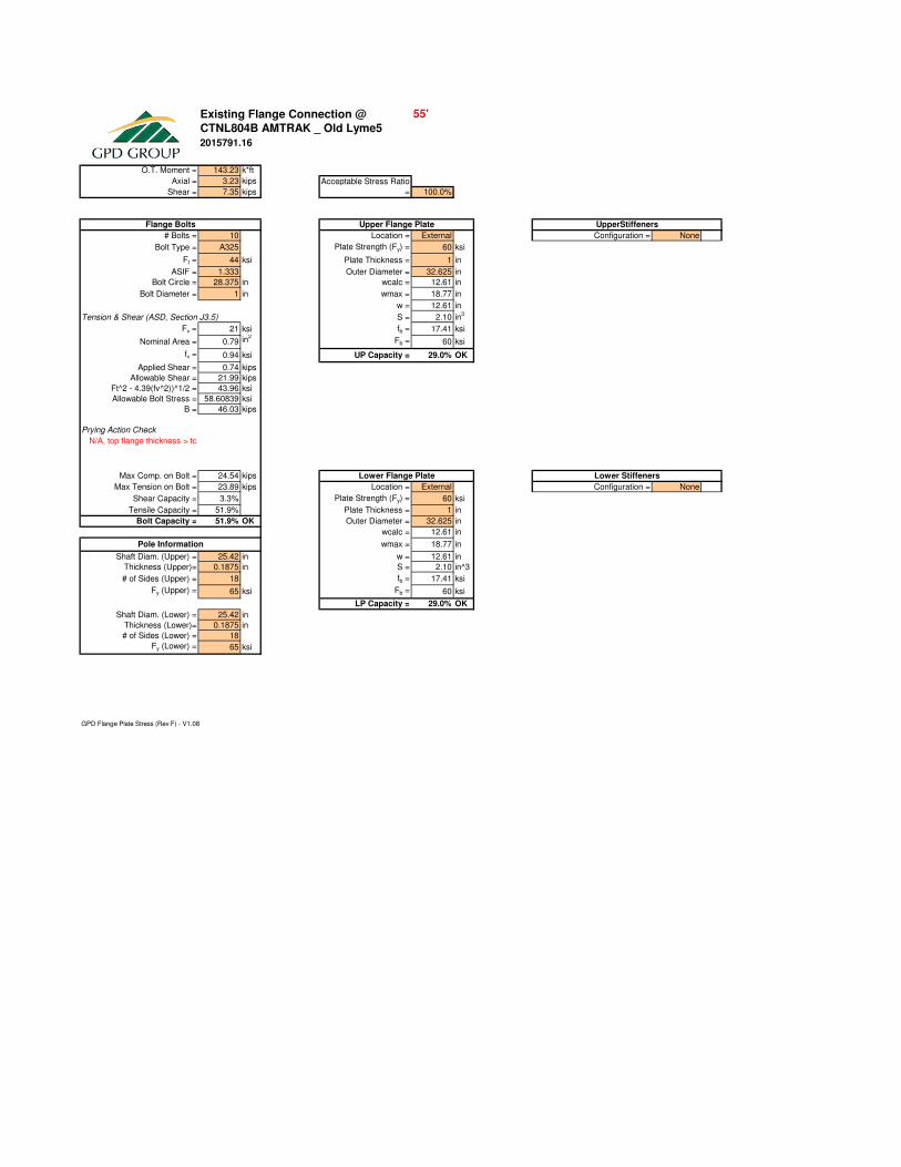
Existing Flange Connection @
O.T. Moment = 143.23 k*ft
Axial = 3.23 kips
Shear = 7.35 kips 100.0%
# Bolts = 10 Location = External Configuration = None
Bolt Type = A325 Plate Strength (Fy) = 60 ksi Thickness = 0.5 in
Ft = 44 ksi Plate Thickness = 1 in Width = 2 in
ASIF = 1.333 Outer Diameter = 32.625 in Notch = 0.5 in
Bolt Circle = 28.375 in wcalc = 12.61 in Height = 3 in
Bolt Diameter = 1 in wmax = 18.77 in Stiffener Strength (Fy) = 50 ksi
w = 12.61 in Clear Spacing b/w Stiffeners= 5 in
Tension & Shear (ASD, Section J3.5) S = 2.10 in3
Weld Info. Known? = Yes
Fv = 21 ksi fb = 17.41 ksi Vertical Weld Size = 0.25 in
Nominal Area = 0.79 in2
Fb = 60 ksi Horiz. Weld Type = Both
fv = 0.94 ksi UP Capacity = 29.0% OK Groove Angle = 45 deg
Applied Shear = 0.74 kips Groove Size = 0.1875 in
Allowable Shear = 21.99 kips Fillet Size = 0.25 in
Ft^2 - 4.39(fv^2))^1/2 = 43.96 ksi Weld Strength = 70 ksi
Allowable Bolt Stress = 58.60839 ksi Stiffener Vertical Force = #VALUE! kips
B = 46.03 kips Vert. Weld Capacity = #VALUE! kips
Horiz. Weld Capacity = #VALUE! kips
Prying Action Check Stiffener Capacity = #VALUE! kips
N/A, top flange thickness > tc 46.03 kips Controlling Capacity = #VALUE! ###
treq'd = 0.40 in
Max Comp. on Bolt = 24.54 kips
Max Tension on Bolt = 23.89 kips Location = External Configuration = None
Shear Capacity = 3.3% Plate Strength (Fy) = 60 ksi Thickness = 0.5 in
Tensile Capacity = 51.9% Plate Thickness = 1 in Width = 2 in
Bolt Capacity = 51.9% OK Outer Diameter = 32.625 in Notch = 0.5 in
wcalc = 12.61 in Height = 3 in
wmax = 18.77 in Stiffener Strength (Fy) = 50 ksi
Shaft Diam. (Upper) = 25.42 in w = 12.61 in Clear Spacing b/w Stiffeners= 5 in
Thickness (Upper)= 0.1875 in S = 2.10 in^3 Weld Info. Known? = Yes
# of Sides (Upper) = 18 fb = 17.41 ksi Vertical Weld Size = 0.25 in
Fy (Upper) = 65 ksi Fb = 60 ksi Horiz. Weld Type = Both
LP Capacity = 29.0% OK Groove Angle = 45 deg
Shaft Diam. (Lower) = 25.42 in Groove Size = 0.1875 in
Thickness (Lower)= 0.1875 in Fillet Size = 0.25 in
# of Sides (Lower) = 18 Weld Strength = 70 ksi
Fy (Lower) = 65 ksi Stiffener Vertical Force = #VALUE! kips
Vert. Weld Capacity = #VALUE! kips
Horiz. Weld Capacity = #VALUE! kips
Stiffener Capacity = #VALUE! kips
Controlling Capacity = #VALUE! ###
GPD Flange Plate Stress (Rev F) - V1.08
Lower Stiffeners
CTNL804B AMTRAK _ Old Lyme5
2015791.16
Flange Bolts UpperStiffeners
Pole Information
Upper Flange Plate
55'
Lower Flange Plate
Acceptable Stress Ratio
=

80 Ft. Monopole - Structural Evaluation CTNL804B AMTRAK_OldLyme5
August 28, 2015
APPENDIX E
Anchor Rod & Base Plate Analysis

Overturning Moment = 658.61 k*ft
Axial Force = 9.28 k
Shear Force = 11.86 k 100.0%
Pole Diameter = 36.77 in Plate Strength (Fy) = 50 ksi
Number of Rods = 12 Plate Thickness = 2.5 in
Type = Upset Rod Plate Width = 43.5 in
Rod Yield Strength (Fy) = 75 ksi Est. Dist. b/w ea. Rod = 6 in
ASIF = 1.333 wcalc = 36.881 in
Rod Circle = 42.75 in wmax = 24.748 in
Rod Diameter = 2.25 in w = 24.75 in
Net Tensile Area = 3.25 in2
S = 25.78 in3
Max Tension on Rod = 60.77 kips fb = 17.21 ksi
Max Compression on Rod = 62.31 kips Fb = 50 ksi
Allow. Rod Force = 195.00 kips Base Plate Capacity = 34.4% OK
Anchor Rod Capacity = 31.2% OK
GPD Unstiffened Square Base Plate Stress (Rev F) - V2.07
Anchor Rod and Base Plate Stresses
CTNL804B AMTRAK _ Old Lyme5
Anchor Rods Base Plate
Acceptable Stress Ratio =
2015791.16
80 Ft. Monopole - Structural Evaluation CTNL804B AMTRAK_OldLyme5
August 28, 2015
APPENDIX F
Foundation Analysis
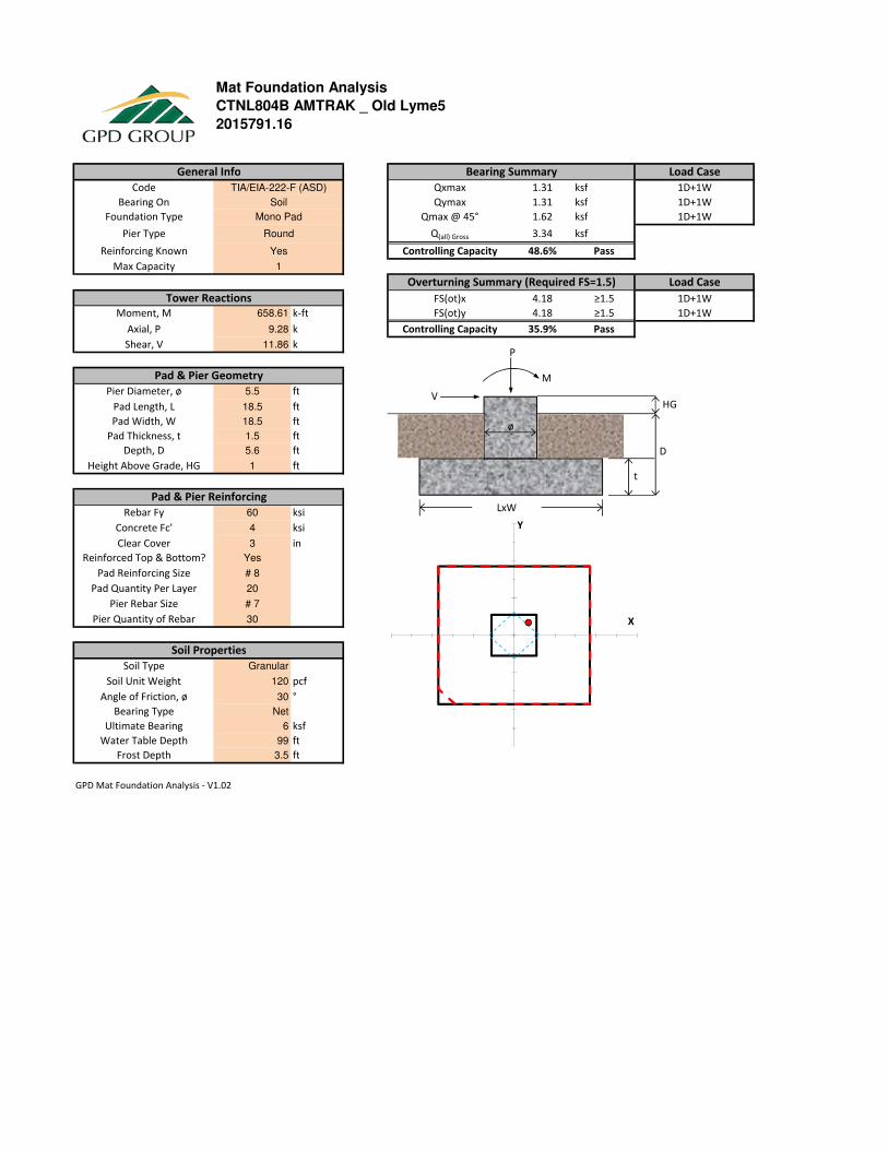
Mat Foundation Analysis
1.31 ksf
1.31 ksf
1.62 ksf
3.34 ksf
48.6% Pass
4.18 ≥1.5
658.61 k-ft 4.18 ≥1.5
9.28 k 35.9% Pass
11.86 k
5.5 ft
18.5 ft
18.5 ft
1.5 ft
5.6 ft
1 ft
60 ksi
4 ksi
3 in
Yes
# 8
20
# 7
30
Granular
120 pcf
30 °
Net
6 ksf
99 ft
3.5 ft
GPD Mat Foundation Analysis - V1.02
Ultimate Bearing
Soil Type
Pier Rebar Size
Soil Unit Weight
Moment, M
Axial, P
Shear, V
Height Above Grade, HG
Pad & Pier Reinforcing
Pad Length, L
Pad Width, W
Pad Thickness, t
Depth, D
Pier Diameter, ø
Pad & Pier Geometry
CTNL804B AMTRAK _ Old Lyme5
Code
Reinforcing Known
Foundation Type
Pier Type
Bearing Summary
Qxmax
Qymax
Qmax @ 45°
Controlling CapacityYes
General Info
SoilBearing On
2015791.16
FS(ot)x
FS(ot)y
Controlling Capacity
Round Q(all) Gross
Overturning Summary (Required FS=1.5)
TIA/EIA-222-F (ASD)
Mono Pad
1
Tower Reactions
Soil Properties
Load Case
1D+1W
1D+1W
Frost Depth
Angle of Friction, ø
Bearing Type
Pier Quantity of Rebar
Max Capacity
Rebar Fy
Pad Quantity Per Layer
Concrete Fc'
Clear Cover
Reinforced Top & Bottom?
Pad Reinforcing Size
Water Table Depth
1D+1W
Load Case
1D+1W
1D+1W
LxW
t
D
HG
ø
V
P
M
X
Y
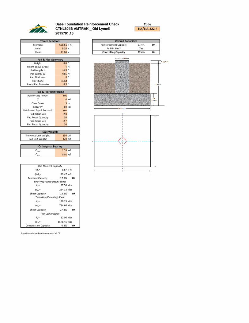
Base Foundation Reinforcement Check
658.61 k-ft 27.4% OK
9.28 k Yes <--- Reinforcement unknown; minimums assumed
11.86 k 27.4% OK
5.6 ft
1 ft
18.5 ft
18.5 ft
1.5 ft
Round
5.5 ft
Yes
4 ksi
3 in
60 ksi
Yes
# 8 # 8
20 15
# 7
30
150 pcf
120 pcf
1.53 ksf
0.01 ksf
18.05 ft
8.87 k-ft
49.47 k-ft
17.9% OK
37.50 kips
284.32 kips
13.2% OK
196.15 kips
714.60 kips
27.4% OK
12.06 kips
6578.45 kips
0.2% OK
Base Foundation Reinforcement - V1.09
φMn=
Unit Weights
Pad Thickness
Pier Rebar Quantity
Two-Way (Punching) Shear
Vu=
Compression Capacity
φVn=
Shear Capacity
Pier Compression
Pu=
φPn=
Moment Capacity
One-Way (Wide-Beam) Shear
Vu=
φVn=
Shear Capacity
Height
Clear Cover
Height above Grade
Pad & Pier Reinforcing
fc'
Round Pier Diameter
Pad Rebar Size
Reinforcing Known
Pad Moment Capacity
Pad Length, L
Pad Width, W
Tower Reactions
Axial
Pad & Pier Geometry
Reinforcement Capacity
Shear
Overall Capacities
Moment
Code
TIA/EIA-222-FCTNL804B AMTRAK _ Old Lyme5
2015791.16
Controlling Capacity
As Min Met?
Mu=
Pier Shape
Orthogonal Bearing
Bearing Length
Qmax
Qmin
Rebar Fy
Pad Rebar Quantity
Pier Rebar Size
Reinforced Top & Bottom?
Concrete Unit Weight
Soil Unit Weight