Embed Size (px)
Citation preview
MODIFICATION OF REINFORCED CONCRETE RETAINING WALL AT PILANGBANGO RESERVOIR CONSTRUCTION PROJECT MADIUN,
EAST JAVA
Mudji Irmawan1, Yerry Kahaditu Firmansyah.2 , Afif Navir Refani 3
1 Program Studi Teknik Sipil FTSP ITS, Surabaya 2 Universitas Pembangunan Nasional “ Veteran“ Jawa Timur
3 Program Studi Diploma Teknik Sipil FTSP ITS, Surabaya E-Mail : [email protected], [email protected], [email protected]
ABSTRACT The reservoir is the tendon of water in order to accommodate the excess rain water in the rainy season and its
utilization in the dry season for various purposes, both in the field of agriculture as well as the interests of the community. To find out the cause of the crack wall of the reservoir Pilangbango Madiun, East Java, then do the test strongly press on concrete walls and soil investigations on the area of the reservoir. Spunpile 400 mm in diameter used by the mounting distance 200 cm and a depth of 12 m and pole mounted on the heels of concrete walls. Manual calculation of the results and analysis of the Finite Element program it can be concluded that in the presence of an additional retaining her 400 spunpile mm using a distance 200 cm and a depth of 12 m, retaining wall construction is then quite able to hold style pillow case and Sliding with style has a safety factor more than 1.5. So the movement of the sliding walls do not happen again. Keywords : Reservoir wall stability, Reinforcement modification, Finite Element.
I. INTRODUCTION
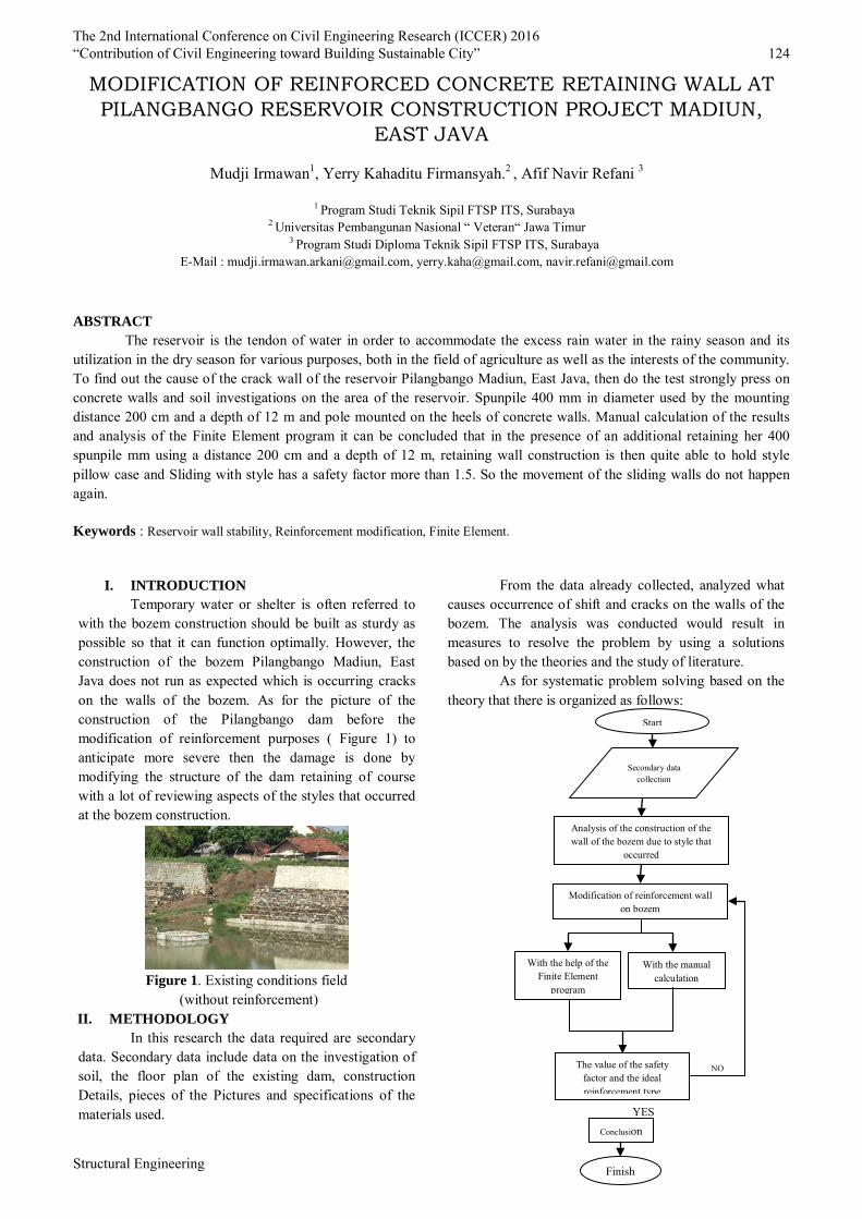
Temporary water or shelter is often referred to with the bozem construction should be built as sturdy as possible so that it can function optimally. However, the construction of the bozem Pilangbango Madiun, East Java does not run as expected which is occurring cracks on the walls of the bozem. As for the picture of the construction of the Pilangbango dam before the modification of reinforcement purposes ( Figure 1) to anticipate more severe then the damage is done by modifying the structure of the dam retaining of course with a lot of reviewing aspects of the styles that occurred at the bozem construction.
Figure 1. Existing conditions field
(without reinforcement) II. METHODOLOGY
In this research the data required are secondary data. Secondary data include data on the investigation of soil, the floor plan of the existing dam, construction Details, pieces of the Pictures and specifications of the materials used.
From the data already collected, analyzed what causes occurrence of shift and cracks on the walls of the bozem. The analysis was conducted would result in measures to resolve the problem by using a solutions based on by the theories and the study of literature.
As for systematic problem solving based on the theory that there is organized as follows:
Modification of reinforcement wall on bozem
With the help of the Finite Element
program
With the manual calculation
The value of the safety factor and the ideal reinforcement type
Conclusion
Finish
NO
YES
Start
Secondary data collection
Analysis of the construction of the wall of the bozem due to style that
occurred
The 2nd International Conference on Civil Engineering Research (ICCER) 2016 “Contribution of Civil Engineering toward Building Sustainable City” 124
Structural Engineering

III. RESULTS AND DISCUSSION Ground investigation data used in the analysis of
retaining wall of the bozem is the borehole B-1 because it is considered to have a tendency of value N-SPT is relatively small. As for the Division of the soil layers in the Finite Element modelling will be done is as follows:
Above ground as well as data from Picture 1. Existing conditions field (without any reinforcement purposes) then gained modeling for Finite Element as follows: a) Analysis With The Finite Element Program (without any reinforcement purposes)
Figure 2. Initial Sketch Modeling
Figure 3. Distribution Voltage that occurs
(without retaining)
Figure 4. Calculations Result The obtained Values
SF 1.04 From the results of the analysis above, that the
structure of the dam without retaining additional security number value obtained amounted to 1.04. To increase the number of security then used an additional retaining the form of spunpile and pair of stone times. As for retaining models that will be done is as follows:
-10,5 -4,5
N – SPT = 12 ; γsat = 18,93 kN/m3 ; c’ = 14,74 kPa ; ϕ = 21°
Silty Sand
N – SPT = 20 ; γsat = 17,3 kN/m3 ; c’ = 20,1 kPa ; ϕ = 14°
Clay Silt
N – SPT = 10 ; γsat = 18,51 kN/m3 ; c’ = 16,08 kPa ; ϕ = 19°
Silty Sand
N – SPT = 20 ; γsat = 16,16 kN/m3 ; c’ = 24,12 kPa ; ϕ = 10°
Clay Silt
N – SPT = 50 ; γsat = 16,86 kN/m3 ; c’ = 18,09 kPa ; ϕ = 17°
Silty Sand
16.00
20.00
24.00
0.00
8.00
10.00
14.00
N – SPT = 9 ; γsat = 19,6 kN/m3 ; c’ = 22,7 kPa ; ϕ = 12°
Clay Silt
Cons. Gabion
Retaining Wall
Concrete
Cons. River Stone
The 2nd International Conference on Civil Engineering Research (ICCER) 2016 “Contribution of Civil Engineering toward Building Sustainable City” 125
Structural Engineering
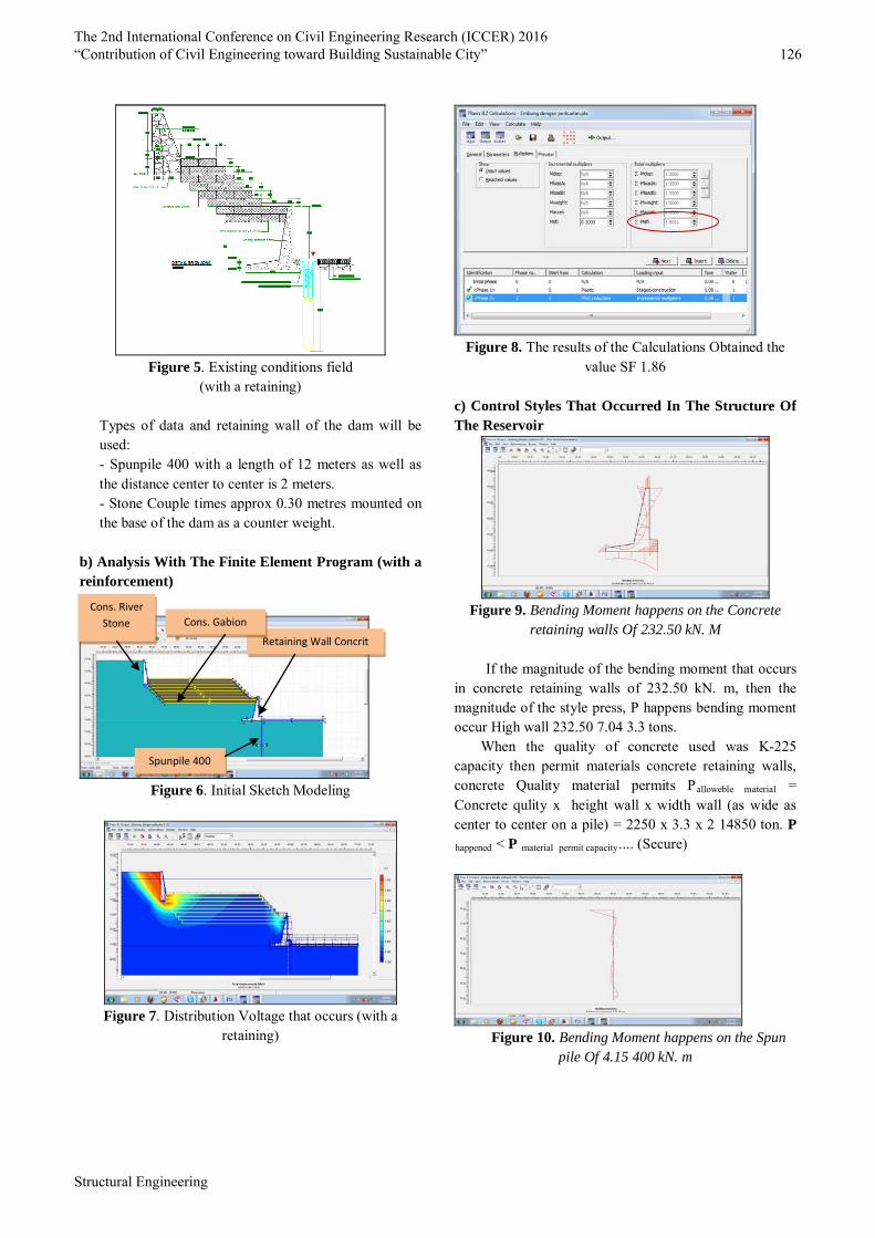
Figure 5. Existing conditions field
(with a retaining)
Types of data and retaining wall of the dam will be used: - Spunpile 400 with a length of 12 meters as well as the distance center to center is 2 meters. - Stone Couple times approx 0.30 metres mounted on the base of the dam as a counter weight.
b) Analysis With The Finite Element Program (with a reinforcement)
Figure 6. Initial Sketch Modeling
Figure 7. Distribution Voltage that occurs (with a
retaining)
Figure 8. The results of the Calculations Obtained the
value SF 1.86 c) Control Styles That Occurred In The Structure Of The Reservoir
Figure 9. Bending Moment happens on the Concrete
retaining walls Of 232.50 kN. M
If the magnitude of the bending moment that occurs in concrete retaining walls of 232.50 kN. m, then the magnitude of the style press, P happens bending moment occur High wall 232.50 7.04 3.3 tons.
When the quality of concrete used was K-225 capacity then permit materials concrete retaining walls, concrete Quality material permits Palloweble material = Concrete qulity x height wall x width wall (as wide as center to center on a pile) = 2250 x 3.3 x 2 14850 ton. P happened < P material permit capacity.... (Secure)
Figure 10. Bending Moment happens on the Spun
pile Of 4.15 400 kN. m
Cons. River Stone
Spunpile 400
Retaining Wall Concrit
Cons. Gabion
The 2nd International Conference on Civil Engineering Research (ICCER) 2016 “Contribution of Civil Engineering toward Building Sustainable City” 126
Structural Engineering

Figure 11. Classification Of The Spun Pile Brochure
To the capacity of the Spun Pile, the magnitude of the bending moment that happened was 0.41 m ton. While capacity materials based on brochure above is 9 m ton. M happened < M material permit …( Secure ) d) Power Control Support Under The Concrete Reinforcement Walls
Figure 12. Construction Of A Concrete Wall. Qult = ½ x γ’ x B x Nγ + C’ x Nc + q x Nq The Foundation Continuously = ½ x 0,96 x 3 x 0,86 + 2,2
x 9,4 + 0 x 5,44 = 21,92 t/m2
If the Foundation width as wide as the center review to center on 2 meters, then: Qult = 21,92 t/m2 x 2 meter x 3,3 meter
= 144,67 ton Qall = Qult / SF
= 48,2 ton where, B = Wide base the foundation ( m )
γ’ = Effective land heavy volume( t/m3 ) = γsat - γw
C’= Effective cohesion land ( t/m2 ) = 2/3 x Cu
q = Load as deep as D from land face lowest ( t/m2 ) D = High foundation ( m ) N γ, Nc, Nq = Reduction Factor ( table )
Table 1. Reduction Factor
Ø° Nc Nγ Nq 0 5.14 0.00 1.00 5 6.50 0.10 1.60 10 8.40 0.50 2.50 15 11.00 1.40 4.00 20 14.80 3.50 6.40 25 20.70 8.10 10.70 30 30.00 18.10 18.40 35 46.00 41.00 33.30 40 75.30 100.00 64.20 45 134.00 254.00 135.00
(Source: Terzaghi K, Peck R.B, 1967)
Calculation of power support permission powerboats spun type diameter of 40 cm with a depth of 12 meters is 41.5 tons, recapitulation of the calculation can be seen in table 2 below.
The 2nd International Conference on Civil Engineering Research (ICCER) 2016 “Contribution of Civil Engineering toward Building Sustainable City” 127
Structural Engineering
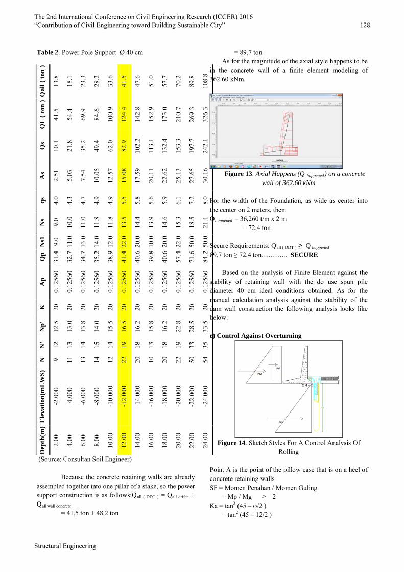
Table 2. Power Pole Support Ø 40 cm Q
all (
ton
)
13.8
18.1
23.3
28.2
33.6
41.5
47.6
51.0
57.7
70.2
89.8
108.
8
QL
( ton
)
41.5
54.4
69.9
84.6
100.
9
124.
4
142.
8
152.
9
173.
0
210.
7
269.
3
326.
3
Qs
10.1
21.8
35.2
49.4
62.0
82.9
102.
2
113.
1
132.
4
153.
3
197.
7
242.
1
As
2.51
5.03
7.54
10.0
5
12.5
7
15.0
8
17.5
9
20.1
1
22.6
2
25.1
3
27.6
5
30.1
6
qs
4.0
4.3
4.7
4.9
4.9
5.5
5.8
5.6
5.9
6.1
7.2
8.0
Ns
9.0
10.0
11.0
11.8
11.8
13.5
14.4
13.9
14.6
15.3
18.5
21.1
Ns1
9.0
11.0
13.0
14.0
12.0
22.0
20.0
10.0
20.0
22.0
50.0
50.0
Qp
31.4
32.7
34.7
35.2
38.9
41.4
40.6
39.8
40.6
57.4
71.6
84.2
Ap
0.12
560
0.12
560
0.12
560
0.12
560
0.12
560
0.12
560
0.12
560
0.12
560
0.12
560
0.12
560
0.12
560
0.12
560
K
20
20
20
20
20
20
20
20
20
20
20
20
Np'
12.5
13.0
13.8
14.0
15.5
16.5
16.2
15.8
16.2
22.8
28.5
33.5
N'
12
13
14
15
14
19
18
13
18
19
33
35
N 9 11
13
14
12
22
20
10
20
22
50
54
Elev
atio
n(m
LWS)
-2.0
00
-4.0
00
-6.0
00
-8.0
00
-10.
000
-12.
000
-14.
000
-16.
000
-18.
000
-20.
000
-22.
000
-24.
000
Dep
th(m
)
2.00
4.00
6.00
8.00
10.0
0
12.0
0
14.0
0
16.0
0
18.0
0
20.0
0
22.0
0
24.0
0
(Source: Consultan Soil Engineer)
Because the concrete retaining walls are already assembled together into one pillar of a stake, so the power support construction is as follows:Qall ( DDT ) = Qall drifen + Qall wall concrete
= 41,5 ton + 48,2 ton
= 89,7 ton As for the magnitude of the axial style happens to be
in the concrete wall of a finite element modeling of 362.60 kNm.
Figure 13. Axial Happens (Q happened) on a concrete
wall of 362.60 kNm
For the width of the Foundation, as wide as center into the center on 2 meters, then: Qhappened = 36,260 t/m x 2 m
= 72,4 ton Secure Requirements: Qall ( DDT ) ≥ Q happened 89,7 ton ≥ 72,4 ton………... SECURE
Based on the analysis of Finite Element against the
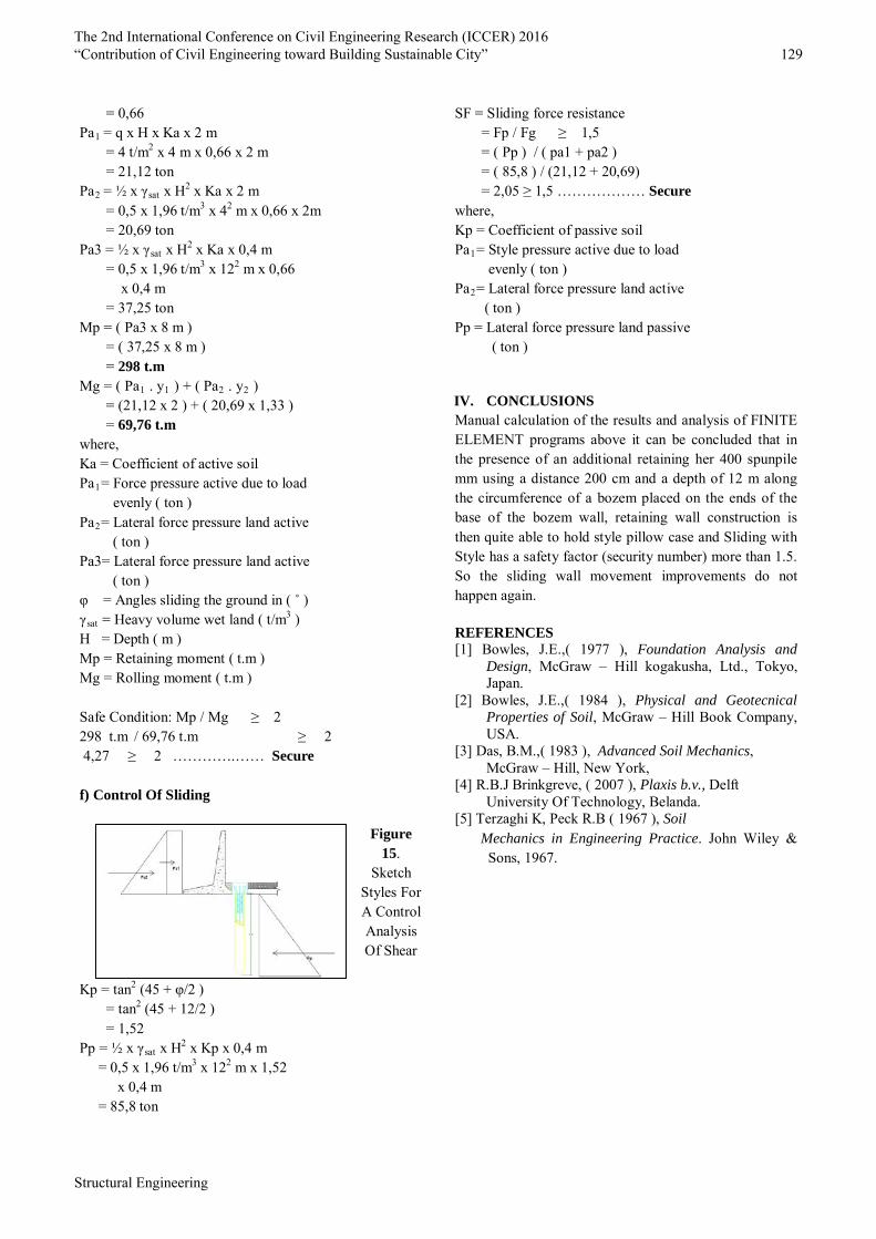
stability of retaining wall with the do use spun pile diameter 40 cm ideal conditions obtained. As for the manual calculation analysis against the stability of the dam wall construction the following analysis looks like below: e) Control Against Overturning
Figure 14. Sketch Styles For A Control Analysis Of
Rolling Point A is the point of the pillow case that is on a heel of concrete retaining walls SF = Momen Penahan / Momen Guling
= Mp / Mg ≥ 2 Ka = tan2 (45 – φ/2 )
= tan2 (45 – 12/2 )
The 2nd International Conference on Civil Engineering Research (ICCER) 2016 “Contribution of Civil Engineering toward Building Sustainable City” 128
Structural Engineering
= 0,66 Pa1 = q x H x Ka x 2 m
= 4 t/m2 x 4 m x 0,66 x 2 m = 21,12 ton
Pa2 = ½ x γsat x H2 x Ka x 2 m = 0,5 x 1,96 t/m3 x 42 m x 0,66 x 2m = 20,69 ton
Pa3 = ½ x γsat x H2 x Ka x 0,4 m = 0,5 x 1,96 t/m3 x 122 m x 0,66 x 0,4 m = 37,25 ton
Mp = ( Pa3 x 8 m ) = ( 37,25 x 8 m ) = 298 t.m
Mg = ( Pa1 . y1 ) + ( Pa2 . y2 ) = (21,12 x 2 ) + ( 20,69 x 1,33 ) = 69,76 t.m
where, Ka = Coefficient of active soil Pa1= Force pressure active due to load evenly ( ton ) Pa2= Lateral force pressure land active ( ton ) Pa3= Lateral force pressure land active ( ton ) φ = Angles sliding the ground in ( ˚ ) γsat = Heavy volume wet land ( t/m3 ) H = Depth ( m ) Mp = Retaining moment ( t.m ) Mg = Rolling moment ( t.m )
Safe Condition: Mp / Mg ≥ 2
298 t.m / 69,76 t.m ≥ 2 4,27 ≥ 2 ………….…… Secure
f) Control Of Sliding
Figure
15. Sketch
Styles For A Control Analysis Of Shear
Kp = tan2 (45 + φ/2 )
= tan2 (45 + 12/2 ) = 1,52
Pp = ½ x γsat x H2 x Kp x 0,4 m = 0,5 x 1,96 t/m3 x 122 m x 1,52
x 0,4 m = 85,8 ton
SF = Sliding force resistance = Fp / Fg ≥ 1,5 = ( Pp ) / ( pa1 + pa2 ) = ( 85,8 ) / (21,12 + 20,69) = 2,05 ≥ 1,5 ……………… Secure
where, Kp = Coefficient of passive soil Pa1= Style pressure active due to load evenly ( ton ) Pa2= Lateral force pressure land active ( ton ) Pp = Lateral force pressure land passive ( ton )
IV. CONCLUSIONS Manual calculation of the results and analysis of FINITE ELEMENT programs above it can be concluded that in the presence of an additional retaining her 400 spunpile mm using a distance 200 cm and a depth of 12 m along the circumference of a bozem placed on the ends of the base of the bozem wall, retaining wall construction is then quite able to hold style pillow case and Sliding with Style has a safety factor (security number) more than 1.5. So the sliding wall movement improvements do not happen again.
REFERENCES [1] Bowles, J.E.,( 1977 ), Foundation Analysis and
Design, McGraw – Hill kogakusha, Ltd., Tokyo, Japan.
[2] Bowles, J.E.,( 1984 ), Physical and Geotecnical Properties of Soil, McGraw – Hill Book Company, USA.
[3] Das, B.M.,( 1983 ), Advanced Soil Mechanics, McGraw – Hill, New York,
[4] R.B.J Brinkgreve, ( 2007 ), Plaxis b.v., Delft University Of Technology, Belanda.
[5] Terzaghi K, Peck R.B ( 1967 ), Soil Mechanics in Engineering Practice. John Wiley &
Sons, 1967.
The 2nd International Conference on Civil Engineering Research (ICCER) 2016 “Contribution of Civil Engineering toward Building Sustainable City” 129
Structural Engineering