Embed Size (px)
Citation preview
.. %- _
NASATechnical
Paper_-- 3054
November 1990
• .+_
}"
L-+_+ - . +_ _ _ ._- : - .
_ . +
Thermal-Distortion Anaiy_ ::
, of a Spacecraft Boxin Geostationary
Patrick A. Cosgrove,
Jeffery T. Farmer,
and Lawrence F. Rowell
- . +_+
- .+.
Truss: (
Orbit _!:: :
. -.- - ,_ +
P_+ r+L + - + + " -.r"
+
+ "
- " .-+I- ' " : =
-_ _ _ +
=: - =- .
- c'-:--:
+{/ +
.-.- ?
i" . .
+
:,_ _ ,r T "+ | '+ -" _" + "-tq r
' i _ .. " _";,,T _. ._ .v
_." L I_ _"
https://ntrs.nasa.gov/search.jsp?R=19910001728 2018-05-18T22:01:17+00:00Z

2
2
NASATechnical
Paper3054
1990
National Aeronautics andSpace Administration
Office of Management
Scientific and TechnicalInformation Division
Thermal-Distortion Analysisof a Spacecraft Box Trussin Geostationary Orbit
Patrick A. Cosgrove
Lockheed Engineering & Sciences Company
Hampton, Virginia
Jeffery T. Farmer and Lawrence F. Rowell
Langley Research Center
Hampton, Virginia

Summary
The Mission to Planet Earth program may en-
list the use of geostationary platforms to supportEarth-science monitoring instruments. The strong-
back for a proposed geostationary platform is a de-
ployable box truss that supports two large-diameter
passive microwave radiometers (PMR's) and severalother science instruments. A study was made to es-
timate the north-south and east-west pointing errors
at the mounting locations of the two PMR's due toon-orbit thermal distortions of the main truss. The
baseline configuration for the main truss was modeled
as untreated graphite/epoxy composite truss mem-bers and end fittings to illustrate typical thermal be-
haviors for structures of this type.
Analytical results of the baseline configuration in-dicated that the east-west pointing error greatly ex-
ceeded the required limits. Primary origins of the
pointing errors were identified, and methods for theirreduction were addressed. Thermal performance en-hancements to the truss structure were modeled and
analyzed, including state-of-the-art surface coatingsand insulation techniques. Comparisons of the ther-mal enhancements to the baseline were made. Re-
sults demonstrated that using a thermal-enclosure in-
sulating technique reduced external heat fluxes anddistributed those heat fluxes more evenly through-
out the structure, sufficiently reducing the pointing
errors induced by thermal distortions to satisfy point-
ing accuracy requirements of the PMR's.
Introduction
The proposed Mission to Planet Earth programwill employ a combination of low Earth orbit (LEO)
and geostationary Earth orbit (GEO) spacecraft asEarth-science instrument platforms. The mission
of the program is to monitor global changes in the
Earth's hydrological, biogeochemical, and climato-
logical cycles. At geostationary altitude, the coor-dination of a small number of spacecraft will facili-
tate continuous coverage of a large percentage of the
Earth's land, ocean, and atmospheric area, as well
as provide high temporal coverage and reduce thenumber of LEO spacecraft required to obtain com-
parable coverage. However, placing the observation
platforms at geostationary altitudes places high de-mands on a broad range of current technologies. Par-
ticularly, advances in technology will be required to
meet high pointing accuracy requirements and pro-
vide the pointing and position knowledge required
intrinsically at GEO.
In order to quantify the needs for such ad-
vanced technology, the NASA Langley Research
Center (LaRC) is studying the performance of a pro-
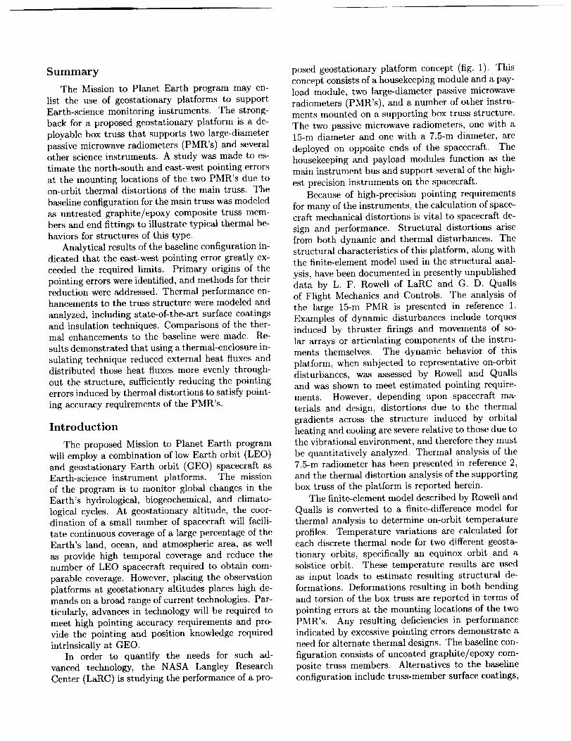
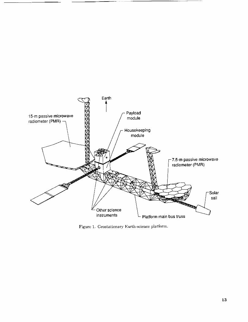
posed geostationary platform concept (fig. 1). This
concept consists of a housekeeping module and a pay-load module, two large-diameter passive microwave
radiometers (PMR's), and a number of other instru-ments mounted on a supporting box truss structure.
The two passive microwave radiometers, one with a15-m diameter and one with a 7.5-m diameter, are
deployed on opposite ends of the spacecraft. The
housekeeping and payload modules function as the
main instrument bus and support several of the high-
est precision instruments on the spacecraft.
Because of high-precision pointing requirements
for many of the instruments, the calculation of space-craft mechanical distortions is vital to spacecraft de-
sign and performance. Structural distortions arise
from both dynamic and thermal disturbances. Thestructural characteristics of this platform, along withthe finite-element model used in the structural anal-
ysis, have been documented in presently unpublished
data by L. F. Rowell of LaRC and G. D. Qualls
of Flight Mechanics and Controls. The analysis of
the large 15-m PMR is presented in reference 1.
Examples of dynamic disturbances include torques
induced by thruster firings and movements of so-
lar arrays or articulating components of the instru-ments themselves. The dynamic behavior of this
platform, when subjected to representative on-orbitdisturbances, was assessed by Rowell and Qualls
and was shown to meet estimated pointing require-
ments. However, depending upon spacecraft ma-
terials and design, distortions due to the thermal
gradients across the structure induced by orbital
heating and cooling are severe relative to those due tothe vibrational environment, and therefore they must
be quantitatively analyzed. Thermal analysis of the
7.5-m radiometer has been presented in reference 2,
and the thermal distortion analysis of the supporting
box truss of the platform is reported herein.
The finite-element model described by Rowell and
Qualls is converted to a finite-difference model for
thermal analysis to determine on-orbit temperature
profiles. Temperature variations are calculated foreach discrete thermal node for two different geosta-
tionary orbits, specifically an equinox orbit and asolstice orbit. These temperature results are used
as input loads to estimate resulting structural de-formations. Deformations resulting in both bending
and torsion of the box truss are reported in terms of
pointing errors at the mounting locations of the two
PMR's. Any resulting deficiencies in performance
indicated by excessive pointing errors demonstrate aneed for alternate thermal designs. The baseline con-
figuration consists of uncoated graphite/epoxy com-
posite truss members. Alternatives to the baseline
configuration include truss-member surface coatings,
multilayerinsulation,anda truss-enclosingthermalblanket.A comparisonoftheperformanceofalterna-tivethermaldesignconceptswiththat ofthebaselineconfiguration is presented.
Spacecraft Concept
Many concepts for a geostationary plat.form have
been proposed in studies performed for NASA by
the General Electric Astro-Space Division, Lockheed
Missiles & Space Company, Ford Aerospace Corpora-
tion, and others. The concept selected for this anal-
ysis resulted from a Ford Aerospace study completed
in 1987, and it is shown in figure 1. It is representa-
tive of the large Earth-science platforms anticipated
to support the high-resolution instruments required
to make global-change measurements. The fact that
the strongback is a large truss, rather than a rigid
panel structure, and can be deployed or erected on-
orbit is also representative of scenarios being pro-
posed for the assembly of large, multidisciplinary
platforms at Space Station Freedom. This spacecraft,
serving as a science instrument platform, must satisfypointing criteria for 18 distinct science instruments
with pointing requirements ranging from 1 to 360 arc-
seconds (arcsec). The main box truss (developed byA. von Roos and J. M. Hedgepeth of Astro Aerospace
Corporation) serves as the strongback for the GEO
spacecraft and is constructed of graphite/epoxy com-
posite tubes designed as a fully deployable, packaged
truss. (Sec sketch A.) The lacing pattern of the truss
is specifically designed to make the structure deploy-
able. The tubes form seven cubic 3.0-m bays and areattached to the truss nodes by graphite end fittings.
Sketch A
The housekeeping module accommodates most of
the spacecraft subsystem components including the
sensors and actuators for attitude control. The point-
ing and alignment knowledge and control are im-
plemented at this rigidized point of the spacecraft.
For this reason, the payload module accommodates
those science instruments requiring the highest point-ing precision. These modules are reinforced with
graphite honeycomb panels to provide added stiff-
ness. Since the sensors and actuators for pointing
control are located in the housekeeping and payload
(H/P) modules, the support structure for the H/Pmodules must be designed to eliminate transmission
of mechanical distortions from the spacecraft to the
modules. Therefore, these modules have a very rigidconstruction relative to the box truss.
The 15-m PMR is mounted at the end of the bus
truss nearest the H/P modules, whereas the 7.5-mPMR is at the farthest end in order to balance the so-
lar pressure torques that each PMR encounters. An
adjustable solar sail is also used to provide adapt-
ability to seasonal variations in solar pressure torque.
Other science instruments, mounted at various loca-
tions along the main truss, have stringent pointing re-
quirements that dictate a stiff supporting structure.
Also, accommodating the fields of view of individual
instrument sensors and radiators suggests a complex
system integration and governs the overall configura-tion layout.
Platform Thermal-Structural Model
The structural model of the GEO platform is
a finite-element model (developed by Rowell and
Quails) that is generated with I-DEAS software. (See
the appendix and ref. 3.) The finite-element model is
converted to a finite-difference model using the Ther-
mal Model Generator (TMG). (See the appendix andref. 4.) Because this study addresses the pointing er-
ror inherent in the structure of the spacecraft main
box truss, the portion of the complete platform model
required for this study includes only the components
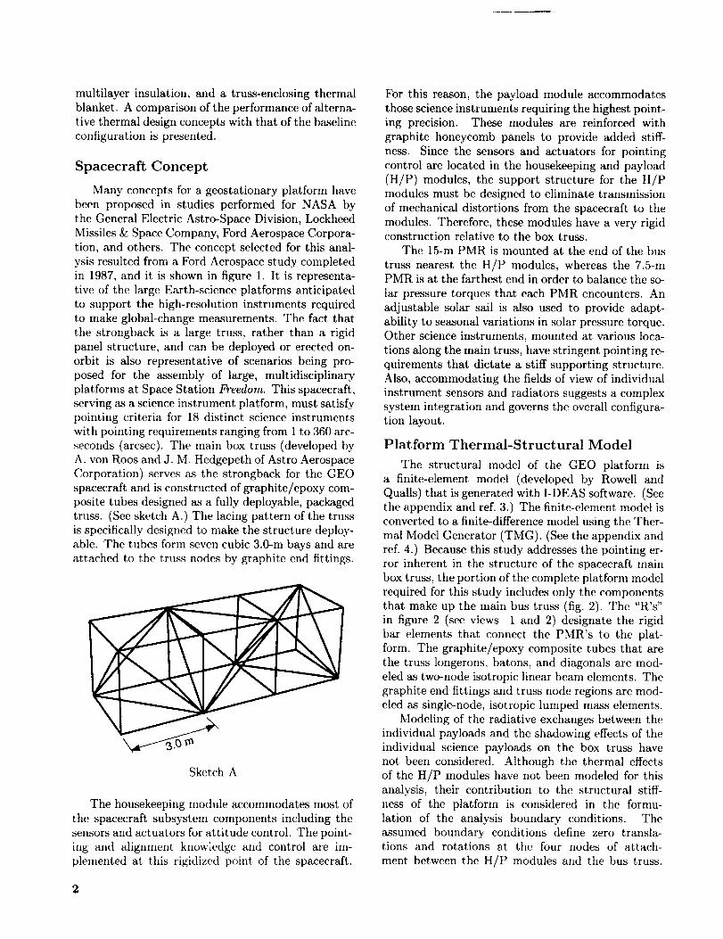
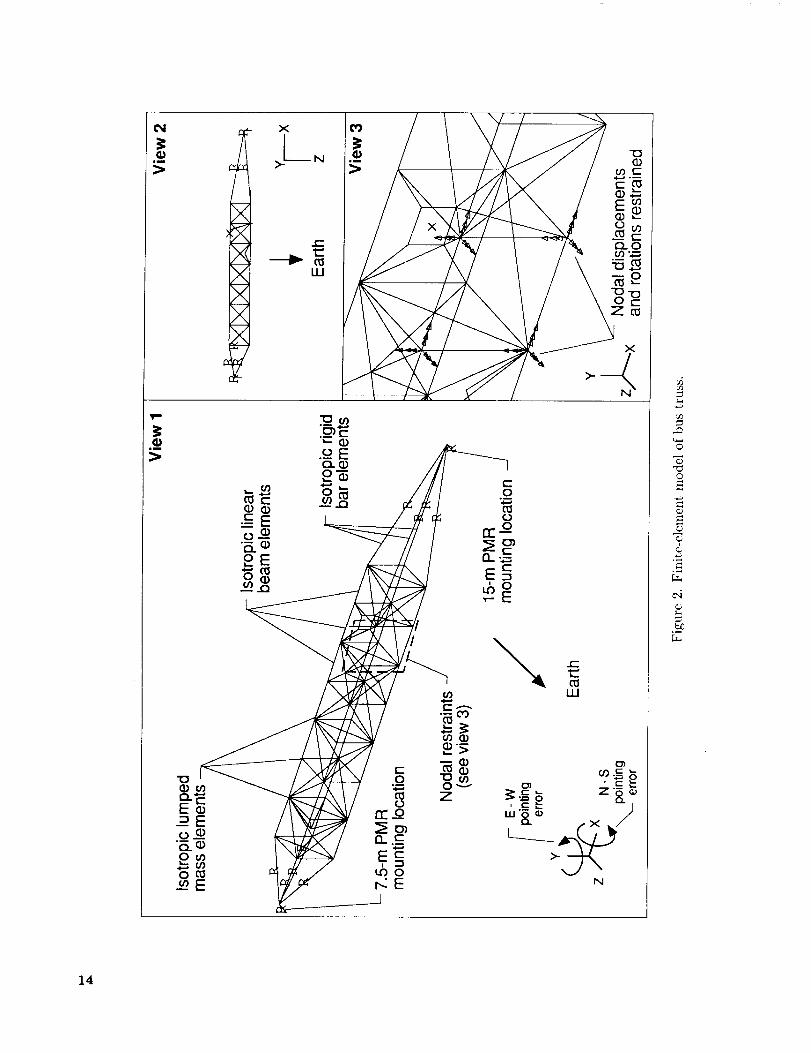
that make up the main bus truss (fig. 2). The "R's"
in figure 2 (see views 1 and 2) designate the rigid
bar elements that connect the PMR's to the plat-
form. The graphite/epoxy composite tubes that are
the truss longerons, batons, and diagonals are mod-eled as two-node isotropic linear beam elements. The
graphite end fittings and truss node regions are mod-
eled as single-node, isotropic lumped mass elements.
Modeling of the radiative exchanges between the
individual payloads and the shadowing effects of the
individual science payloads on the box truss have
not been considered. Although the thermal effects
of the H/P modules have not been modeled for thisanalysis, their contribution to the structural stiff-
ness of the platform is considered in the formu-
lation of the analysis boundary conditions. Theassumed boundary conditions define zero transla-tions and rotations at the four nodes of attach-
ment between the H/P modules and the bus truss.
2
Therefore,anynodaltranslationsor rotationsen-counteredat variouslocationsalongthe trussarecalculatedrelativeto theseboundary-conditionloca-tionsusingtheI-DEASmodelsolutionanalysispack-age. (Seethe appendixand ref. 5.) Therotationof anynodeis consideredanalogousto the point-ing errorfor anyinstrumentmountedat that node.Therefore,pointingerrorsat anynodelocationofthe modelaredeterminedrelativeto theH/P mod-ules. Thermophysicalpropertiesusedin the base-lineanalysisaretakenfromthe analysispresentedin reference2 andaregivenin tableI. Notethat allpropertiesareassumedto beconstantwith respectto temperatureandarerepresentativeof beginning-of-lifevalues.
Table I. Thermophysical Properties of
Finite-Element Model
Linear beam characteristics:
Diameter, mm .................... 51
Thickness, mm .................... 1.6
Average length, m .................. 3.0
Material properties (uncoated P75
graphite/thermoplastic):
Young's modulus, N/m 2 .......... 2.7 × 10¹¹
Mass density, kg/m 3 ............... 1690
Coefficient of thermal expansion
(CTE), m/m-K ............. 0.5 x 10 -6
Thermal conductivity, W/m-K ............ 76
Specific heat, J/kg-K ................ 850
Surface properties:
Solar absorptivity (a) ................ 0.9
Thermal emissivity (e) ............... 0.8
Lumped mass characteristics
(end fittings/truss node region):
Mass, kg ...................... 7.0
Rigid bar characteristics:Infinite stiffness
Nonthermal element
The use of untreated or unprotected graphite in
a geostationary spacecraft design may not be prac-tical because of material lifetime limitations and in-
adequate thermal performance. However, the use of
this configuration serves as a baseline against which
all performance-enhancing treatments or technolo-
gies can be compared.
The performance of the box truss model just de-scribed is measured in terms of east-west and north-
south pointing errors at the two PMR mounting loca-
tions which correspond to nodal rotations about the
model Y-axis and X-axis, respectively (fig. 2). The
PMR mounting locations have been chosen because
they are at the extreme ends of the truss, and it is
anticipated that the pointing errors increase as the
distance from the H/P modules increases. Relativeto the rotations in the X- and Y-axes, the nodal ro-
tations about the model Z-axis are not significant in
terms of the spacecraft performance. The PMR's
must achieve pointing accuracies within 36 arc-
seconds (ref. 6) in the north-south and east-west di-
rections to meet performance specifications.
It is important to note that this specified point-
ing requirement is the maximum allowable total of
all pointing error contributors. Also, pointing errorsfor the PMR's are expressed as positive or negative
errors. Positive pointing error is defined here as aclockwise rotation about an axis when the rotation
is viewed from the origin with the viewer facing in the
positive axis direction, and negative pointing error isa counterclockwise rotation. As expressed previously,
structural distortions of the platform are induced bymechanical disturbances and vibrations as well as by
thermal gradients within the structure. Therefore,
the pointing errors induced by orbital thermal dis-
tortions represent only one part of the total, anddiscretion must be exercised in characterizing a par-
ticular thermal performance as meeting the pointing
requirements.
Scope of Analyses
The intent of this study is to determine the effect
of the geostationary orbit thermal environment on
the pointing performance of the GEO platform in
terms of thermally induced pointing errors at theextreme ends of the box truss. Thermal analyses
provide temperature profiles of the truss as a functionof time in orbit. These temperature profiles serve as
the load sets for the linear static analyses, the results
of which are nodal displacements and rotations.
Details of Thermal Analysis
The thermal environment of the GEO platform
can be broken down into three components of influ-ence: radiative heat fluxes from the Sun and Earth,
radiative and conductive heat exchanges between el-
ements of the platform, and radiative exchange be-
tween the platform and deep space. The view fac-tor between thermal node A and thermal node B
is defined as the fraction of the radiant energy flux
that leaves A which is incident upon B. The solar
absorptivity surface property for a thermal node de-termines the fraction of incident radiant energy flux
that is absorbed, and the thermal or infrared emis-
sivity determines the fraction of blackbody radiant
energy flux that is emitted. Therefore, the radia-tive heat exchanges between the Sun, Earth, and/or
deep space and the truss structure are calculated by
determiningthe orbitalchangesin viewfactorsbe-tweenthem. Similarly,theradiativeheatexchangeswithin the platformare calculated by determiningthe view factors between individual truss members.
Calculations of these view factors and energy ex-
changes are performed by the TMG. (See the ap-
pendix and ref. 4.)
Increases or decreases in solar heating on indi-
vidual truss members are caused by changes in their
orientation relative to the Sun as the spacecraft or-
bits the Earth. The GEO orbit is an equatorial orbit
(0 ° inclination) with a radius of 42 164 km and an
orbital period equal to that of the Earth. In order
to quantify the performance of the box truss with re-
gard to orbital variations, this study considers both
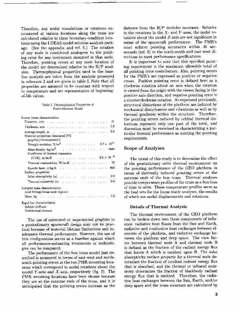
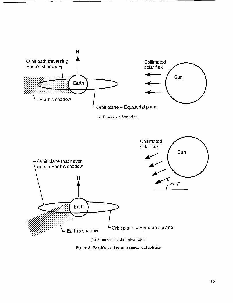
equinox and solstice orbits. Figure 3 shows the rela-
tive orientation of the spacecraft, Earth, and Sun at
equinox and solstice orbits. In the equinox orbit, part
of each orbit passes through the shadow cast by theEarth. The maximum eclipse time is approximately
72 minutes, occurring on both the spring equinox and
the fall equinox. For approximately 22 days on each
side of an equinox there are eclipses of shorter du-
ration. During the remaining days, the spacecraft is
in sunlight for the entire orbit. Over the course of
a year, there are about 50 days with eclipse periods
of more than 1 hour (ref. 7). As the spacecraft en-
ters the Earth's shadow, temperatures fall and will
subsequently rise upon exit from the shadow with theresumption of incident solar flux. Changes in element
temperature in the box truss as it passes through theEarth's shadow lead to deformations and stresses due
to thermal expansion and contraction.
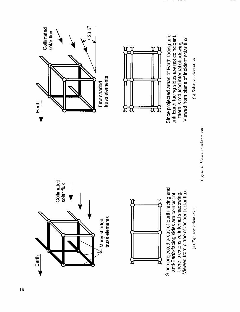
Another shadowing effect occurs when truss mem-
bers are shadowed by other truss members, as de-
picted in figure 4. Note that there are no diagonals
shown in the figure for simplicity of illustration, and
that diagonals have been included for the calculationof view factors. When one truss member shadows
another, the shadowing member intercepts the inci-dent collimated solar flux such that the shadowed
member receives little or no solar flux, thus produc-
ing a thermal gradient in the structure. This internal
shadowing is particularly acute in the equinox orbit
when the longerons of the truss on the Sun's facing
side shadow the longerons of the opposite side be-
cause of their coincident projected areas. Because
this occurs over a large portion of the equinox orbit,
there are long time periods with large temperature
gradients between opposing sides of the truss, with
resulting thermal distortions. In contrast, becauseof the introduction of an incident Sun angle of 23.5 °
with respect to the orbit plane, the internal shad-
owing of the box truss in the solstice orbit is veryminimal.
4
Details of Structural Analysis
Element distortions resulting from thermal ex-
pansions and contractions are expressed in terms of
nodal displacements and rotations. Because adja-
cent elements share common nodes, displacements
and rotations in the structure may be additive from
one element to its connecting elements. To perform
the linear static analysis, boundary conditions in the
form of a restrained set of nodes were necessary. The
mounting location of the H/P modules was chosenas the location for these boundary conditions, such
that the connecting nodes between the H/P modulesand the spacecraft bus truss have their displacements
and rotations restrained. The rigid bar elements that
connect science instrument payloads to the truss are
not thermal elements and, therefore, are not part of
the matrix solution with regard to thermal distor-tions and stresses.
Results of Analysis
Baseline Configuration
Thermal characteristics. The surface proper-ties used in the baseline configuration represent un-
coated graphite/epoxy composite materials with high
solar absorptivity ((_ = 0.9) and emissivity (e = 0.8)for all truss members. High solar absorptivity cor-
responds to a high percentage of incident solar ra-
diation being absorbed, and high emissivity corre-
sponds to a high percentage of blackbody radiation
being emitted. As stated previously, the orientationof truss members relative to the incident solar flux
changes throughout the orbit, and therefore this con-
figuration has wide swings in element heat fluxes.Because the temperature of a truss member is di-
rectly dependent on the net heat flux on its surface,
there are corresponding wide swings in temperatureas the spacecraft proceeds through its orbit. For the
purpose of describing trends in thermal performance
for the cases analyzed, the maximum, minimum, and
average temperatures are specified. Note that for
the purpose of calculating structural distortions and
stresses, the predicted truss member temperatureshave been used.
Equinox orbit: At equinox the minimum and
maximum truss member temperatures for the base-
line case are -172°C and 20°C, respectively, under
transient conditions. Note that these temperaturesare the extremes for the entire model over the en-
tire orbit and refer simply to one particular truss
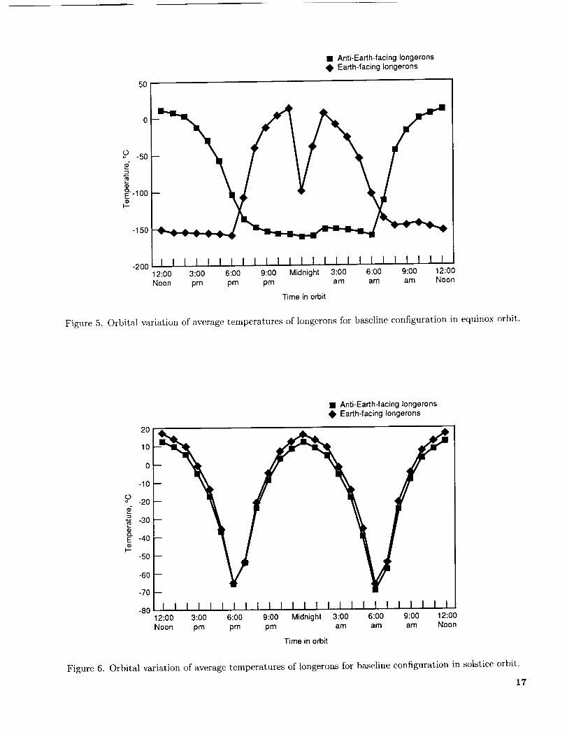
member at one particular time in orbit. Figure 5
shows the average element temperature as a func-
tion of time in equinox orbit for the longerons on the
Earth-facing side and on the anti-Earth-facing side.
Evidentin figure5 arethetwofollowingnoteworthycharacteristics.
The first characteristicis that internalshadow-ing of onesideof the truss by the otheroccurswhenthespacecraftapproacheslocalnoonandmid-night. Figure5 showsthat asthe spacecraftbe-gins its orbit at 12:00noonlocal time, the anti-Earth-facingsideisdirectlyexposedto incidentsolarflux. Internalshadowingeliminatesdirectsolarheat-ing of the Earth-facingside,therebycreatingtem-peraturedifferencesaslargeas170°Cbetweentheaveragetemperatureson theEarth-facingandanti-Earth-facingsidesat that time. Orbitalprogressionthrough6:00pmbringsthe Earth-facingandanti-Earth-facingsidesinto an orientationwheretheirprojectedareasview almostno solarflux, therebygreatlyreducingthetemperaturesof theanti-Earth-facinglongerons.Continuing past 6:00 pm toward
local midnight, the Earth-facing longerons begin to
receive direct solar flux and also begin to shadow the
anti-Earth-facing longerons. This induces a compa-
rable maximum temperature difference as seen ear-
lier, except that the high- and low-temperature sides
have been switched. The temperature profile is re-
versed after local 12:00 midnight, and thus the com-
plete cycle is repeated every 24 hours.
The second characteristic evident in figure 5
is that the spacecraft is in the Earth's shadow
for approximately 1 hour, roughly centered around
12:00 midnight local time. Immediately prior to that
time only the Earth-facing side of the spacecraft is ex-
posed to incident solar flux. The effect of the Earth's
shadow is shown by the sharp drop and subsequent
rise in the temperature curve of the Earth-facing
longeron.
Solstice orbit: The solstice orbit exhibits an in-
cident Sun angle of 23.5 ° with respect to the orbit
plane. This has the effect of exposing to incident so-
lar flux many of the truss members that had beenshaded in the equinox orbit because of the internal
shadowing. Having comparable solar fluxes on most
truss members sharply reduces the temperature vari-
ations across the spacecraft. Figure 6 shows the av-
erage element temperatures as a function of time in
a solstice orbit for the Earth-facing and anti-Earth-
facing longerons. Here the temperature extremes
span only about 80°C, less than half the 170°C span
in the equinox case. Figure 6 also illustrates that
when internal shadowing is reduced, the tempera-
tures of the opposing truss members track each other
and also have greatly reduced temperature differ-ences between them. The temperature difference forthis orbit is on the order of 10°C. Also note that
there is no drop in the temperature curve around lo-
cal midnight because the solstice orbit encounters noEarth shadow.
In the solstice orbit the minimum and maximum
truss member temperatures for the baseline case
are -148°C and 21°C, respectively. The maximum
temperature is approximately the same as in the
equinox orbit and corresponds to truss members
that have complete exposure to the incident solar
flux. The minimum temperature is considerably
higher than that of the equinox orbit. Because the
minimum temperature of a truss member is generallyencountered when the member is shadowed from
solar flux, the reduced occurrences and the duration
of internal shadowing in the solstice orbit result in a
higher minimum temperature.
Structural characteristics. The structural
performance of the GEO platform has been analyzedin terms of the east-west and north-south pointing er-
rors at the mounting locations of the two PMR's. For
all cases analyzed, the assumed coefficient of ther-mal expansion (CTE) is 0.5 × l0 -6 m/m-°C with
an undistorted reference temperature of 22°C. Rela-
tive to this undistorted temperature, higher temper-
ature members expand and lower temperature mem-bers contract. This causes distortions of the truss
members relative to one another. East-west point-
ing error is caused by a temperature gradient be-tween Earth-facing and anti-Earth-facing longerons.
North-south pointing error is due to any uncompen-
sated torsion effects that dissimilar expansions and
contractions of the truss diagonals and batons im-
pose on the spacecraft.
In addition to thermal distortions, orbital temper-ature fluctuations induce thermal stresses in the truss
members. Therefore, analysis of the induced stresses
was undertaken for both the equinox and solstice or-bits. The results indicate that the induced stresses
are far below the critical limits for both Euler buck-
ling and tensile failure. Also, stresses are induced asthe spacecraft enters and exits the Earth's shadow.
Reference 8 suggests that characteristic stresses of
this type are small, and the present analysis confirmsthis result.
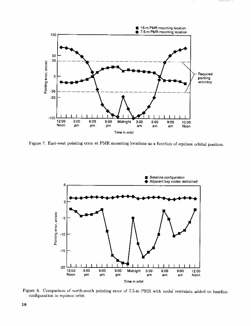
Equinox orbit: Figure 7 shows the east-west
pointing errors for the PMR's as a function of time
in the equinox orbit. Quite prominent in the figure
is that the magnitude of the pointing error of the
7.5-m PMR is much greater than that of the 15-m
PMR. The east-west error of the 15-m PMR rangesfrom 25 to -15 arcseconds and that of the 7.5-m
PMR ranges from 71 to -99 arcseconds. The reason
for the excessive error (i.e., in excess of the speci-
fied limit of 36 arcseconds) of the 7.5-m PMR is that
internal longeron shadowing creates large east-west
pointingerrors,andthis effectis additivefromonebay to the next. Therefore,thecombinedpointingerrorsof thefivebaysthat separatethe7.5-mPMRfromtheH/P modulesexceedthoseof theonebaybetweentheH/P moduleandthe 15-mPMR.
Figure7 alsoshowsa sharpdecreasein themag-nitudeof the pointingerroraroundthe orbit timeof 11:30pmwhenthe spacecraftentersthe Earth'sshadow.During this time all trusselementshavea commonsinkandtemperaturesapproachunifor-mity. In addition,thesignof theeast-westpointingerrorschangesaround6:00pmandagainat around6:00am. (Again,positivepointingerror is definedasa clockwiserotationaboutanaxiswhentherota-tion isviewedfromtheoriginwith theviewerfacingin thepositiveaxisdirection.)Thesetwotimesindi-catewhentheaxisoftraveloftheplatformisparallelwith thecollimatedsolarflux anddefinethepointofthe orbit wherethetrussswitchesSun-facingsides.Consequently,the sidesin contractionand expan-sionareswitched,andthereforethe rotationaboutthemodelY-axis, analogous to east-west pointing er-
ror, reverses sign around 6:00 pm and again around6:00 am.
For the equinox case, the north-south pointing
error of the 15-m PMR ranges from 15 to -3 arc-
seconds, and that of the 7.5-m PMR ranges from -2
to -19 arcseconds. These pointing errors are well
within the specified limit of 36 arcseconds. The lac-
ing pattern of the truss is such that the torsion effect
in one bay is offset with opposing torsion effects in
an adjacent bay. As illustrated by the finite-elementmodel in figure 2, there are five truss bays between
the H/P module and the 7.5-m PMR and one truss
bay between the H/P module and the 15-m PMR.Because of the uneven number of bays in each case
and because the lacing pattern, chosen for deploy-
ability, causes adjacent bays to oppose each other
in torsion, there are unopposed torsion effects man-
ifested in north-south pointing errors that are com-
parable at each PMR. This effect was verified for the
7.5-m PMR by restraining the truss bay adjacent to
the H/P module, thus canceling the torsion effects
in that bay and resulting in a nearly zero net north-
south pointing error for the 7.5-m PMR. Figure 8shows the reduction in the north-south pointing er-ror of the 7.5-m PMR when the structural model has
additional restrained nodes in the bay adjacent to the
H/P module bay.
There are various means by which the structure
could conceivably be designed to yield balanced tor-
sion effects, thus greatly reducing or eliminating the
north-south pointing error. Having an even num-
ber of unrestrained bays would provide this balanc-
ing. Also, because the torsion effects are conveyed
through the truss diagonals, altering the diagonal lac-
ing pattern of the spacecraft would likely have signif-icant effects on the north-south error. Each of these
design choices may impart a potentially significant
impact on other aspects of the total design, and such
design changes would require careful examination.
Solstice orbit: As demonstrated in the previous
section, the large temperature difference between the
Earth-facing and anti-Earth-facing longerons in the
equinox orbit is the primary cause for the east-west
pointing error. Because the incident Sun angle in the
solstice orbit reduces internal shadowing effects, no
large temperature differences exist. Therefore, the
east-west pointing errors are greatly reduced in the
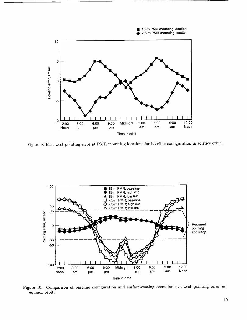
solstice orbit. Figure 9 shows the east-west pointingerrors of the 15-m and 7.5-m PMR's as a function
of time in the solstice orbit. The east-west pointing
error of the 15-m PMR ranges from 6 to -2 arc-
seconds, and that of the 7.5-m PMR ranges from 0
to -9 arcseconds. Comparing the figures of equinox
pointing error and solstice pointing error illustrates
that the equinox orbit is far more severe and shouldbe considered the worst-case orbital environment for
this analysis.
As was the case in the equinox orbit, the north-
south pointing error is caused by unbalanced torsion
effects. The north-south pointing error of the 15-m
PMR ranges from 2 to -17 arcseconds, and that ofthe 7.5-m PMR ranges from 14 to -8 arcseconds.
Balancing the torsion effects of the diagonals and
batons by restraining the adjacent bay, as discussed
previously, resulted in the practical elimination of the
north-south pointing errors.
Thermal Performance Enhancements
The excessive east-west pointing errors in the
equinox orbit described above dictate that thermal
performance enhancements of the spacecraft mainbus truss are necessary. Several enhancements were
analyzed and are summarized in table II. These in-
clude surface coatings, multilayer insulation (MLI),
and a thermal enclosure of aluminized Du Pont Kap-
ton. The capabilities of the performance enhance-
ments to reduce moderate temperature gradients in
the truss, thus reducing east-west pointing error un-
der equinox orbital conditions, are compared. North-
south pointing errors have also been examined for all
the cases listed. Because the magnitude of the er-rors is within the specified limits and because of the
previously discussed dependence of the error on the
truss design (lacing pattern, number of bays, etc.),the north-south results will not be presented.
Surface coatings. In general, surface coatings
are applied directly to graphite structural members
to protectthemfromvariouselementsof the spaceenvironmentin orderto tempertheir thermalre-sponseandincreasetheir lifetime.Morespecifically,for this analysisthe intentis to adjustthe ratio ofsolarabsorptivityto emissivity(a/c) soasto pro-ducea favorableenergybalancefor the structure.Thesurfacecoatingsusedin thisanalysisconsistofthin layersof etchedaluminum.Thedifferenta/e
ratio of each coating is obtained by varying the con-
trol parameters of the etching process (ref. 9). Fig-
ure 10 shows the east-west pointing error of the 7.5-m
and 15-m PMR's for the two surface-coated config-
urations superimposed on the results of the baseline
configuration discussed previously.
Table II. Analysis Cases
Cases
1
Thermal performance
Configuration enhancementBaseline
2 Low a/e
3 High a/e
4 MLI sleeving
5 First thermal
blanket
6 Final thermal
blanket
Truss members constructed
of uncoated graphite with
a/e = 0.9/0.8Truss members constructed
of surface-coated graphite
with a/e = 0.3/0.65Truss members constructed
of surface-coated graphite
with a/e = 0.3/0.2Truss members individually
wrapped with MLI with an
effective a/e of 0.05/0.05Uncoated-graphite box truss
wrapped in an aluminized
Kapton blanket with an
outside-surface a/e of
0.3/0.2 and an inside-
surface a/e of 0.9/0.8
Uncoated-graphite box trusswrapped in an aluminized
Kapton blanket with anoutside-surface a/e of
0.3/0.65 and an inside-
surface a/e of 0.3/0.2
First coating: The first surface coating employed
a low ale ratio of 0.3/0.65 which decreased theamount of solar radiation absorbed in the sunlit por-
tions of the orbit and slightly decreased the amountof emitted radiation at lower temperatures. How-
ever, the decrease in emitted radiation was not great
enough to offset the more substantial reduction inabsorbed radiation. The result was that the overall
heat balance was not greatly affected and the temper-
ature gradient between opposing longerons remained
quite large. Therefore, the overall effect on the point-
ing performance of the spacecraft was not substan-
tial, and in the equinox orbit the calculated east-west
pointing errors remained in excess of the specifiedlimit of 36 arcseconds.
Second coating: The second surface coating em-
ployed a high a/_ ratio of 0.3/0.2 which further de-creased the emitted thermal radiation from individ-
ual bus truss members to deep space, especially dur-
ing shadowing, and also decreased the absorbed solarradiation incident on the truss members during their
sunlit periods. Although the change in surface prop-
erties did slightly improve the pointing error of the
PMR's around solar midnight, there was virtually no
change at other points in the orbit.
The effectiveness of the baseline and the surface-
coated configurations relative to one another varies
with orbit position. Although neither of the coat-
ing concepts sufficiently lowers the error to within
specified limits, the low-ratio coating has a slightly
better performance. By maintaining cooler tempera-
tures on those truss members exposed to direct solar
radiation, the low-ratio coating reduces the temper-
ature difference between opposing sides of the truss,
thereby reducing the east-west pointing errors.
MLI sleeving. The third performance enhance-
ment analyzed was a sleeving of MLI wrapped around
individual truss members. By wrapping the individ-ual truss members with MLI, the added thermal re-sistance serves as a radiative buffer between the or-
bital environment and the structure. The effective
radiative properties of the truss members wrappedwith MLI were assumed to have a solar absorptivity
of 0.05 and an emissivity of 0.05. The lower solar
absorptivity and emissivity significantly reduce the
temperature gradients between the Earth-facing and
anti-Earth-facing sides of the truss, thus reducing
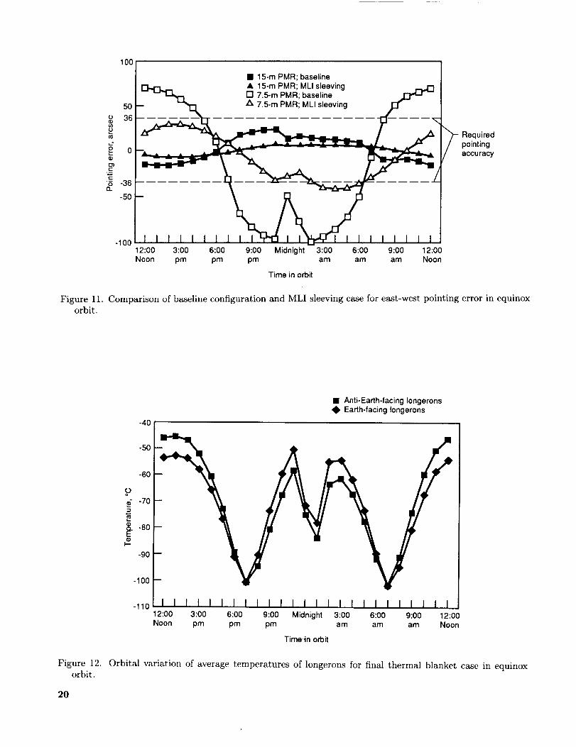
the pointing error by a proportionate amount. How-
ever, in the equinox orbit internal shadowing still oc-
curs, which causes temperature differences between
the Earth-facing and anti-Earth-facing sides. The
equinox orbit pointing error in the east-west direc-tion of the 7.5-m PMR for this analysis case (fig. 11)
ranged from -40 to 30 arcseconds. Although theseresults approach the specified pointing requirements,
for a few analysis points in the orbit, they do remain
outside the specified limit.
Thermal blanket. A thermal blanket is an in-
sulating technique that wraps the entire box truss
with an aluminized Kapton sheet. The blanket ra-
diatively decouples the truss structure from the or-bital environment and eliminates internal shadowing,
7
therebygreatlyreducingtheunevendistributionsintheabsorbedandemittedradiativeheatfluxes.Thiseliminatesthe largetemperaturedifferencebetweenEarth-facingandanti-Earth-facingsidesof thestruc-ture which,asthe baselineanalysisshowed,is theprimarycauseof largeeast-westpointingerrors.Ananalysisof thethermalblanketinsulatingtechniqueresultedin pointingerrorsthat werewellwithin therequiredlimits. Twoanalyticaliterationswereun-dertaken.Thefirst iterationusedsurfacepropertiesof uncoatedgraphitefor thetrussbeamsandthein-nersideofthethermalblanketandasurfacecoatingwith an a/e ratio of 0.3/0.2 on the outside of the
blanket. Pointing performance was excellent, with a
maximum east-west pointing error of -8 arcseconds
for the 7.5-m PMR. However, because the ratio of
absorptivity to emissivity of the outside surface was
greater than unity, the absorbed solar radiation dom-
inated the heat balance and the maximum temper-
ature of the thermal blanket exceeded l l0°C, which
is beyond the material limits of Kapton.The second iteration of the thermal blanket de-
sign employed an uncoated-graphite surface on the
truss beams, a low a/e ratio (0.3/0.65) surface coat-ing on the outside surface of the blanket, and a
low-emissivity (0.2) coating on the inside surface.
The high-emissivity outside surface was very effec-
tive in increasing the emitted radiation, and the low-
emissivity coating on the inside surface decreased theamount of heat radiated to the truss from the blan-
ket. Using this configuration reduced the maximum
blanket temperature to within the material limits of
the Kapton without adversely affecting the east-west
pointing error by a significant amount. At equinox,
the minimum and maximum truss member temper-atures are -114°C and -39°C, respectively. Fig-
ure 12 shows average element temperature as a func-tion of time in equinox orbit for Earth-facing and
anti-Earth-facing longerons of this thermal blanket
configuration. Of particular interest is the excel-
lent temperature tracking, indicating reduced tem-
perature gradients and resulting in smaller pointingerrors.
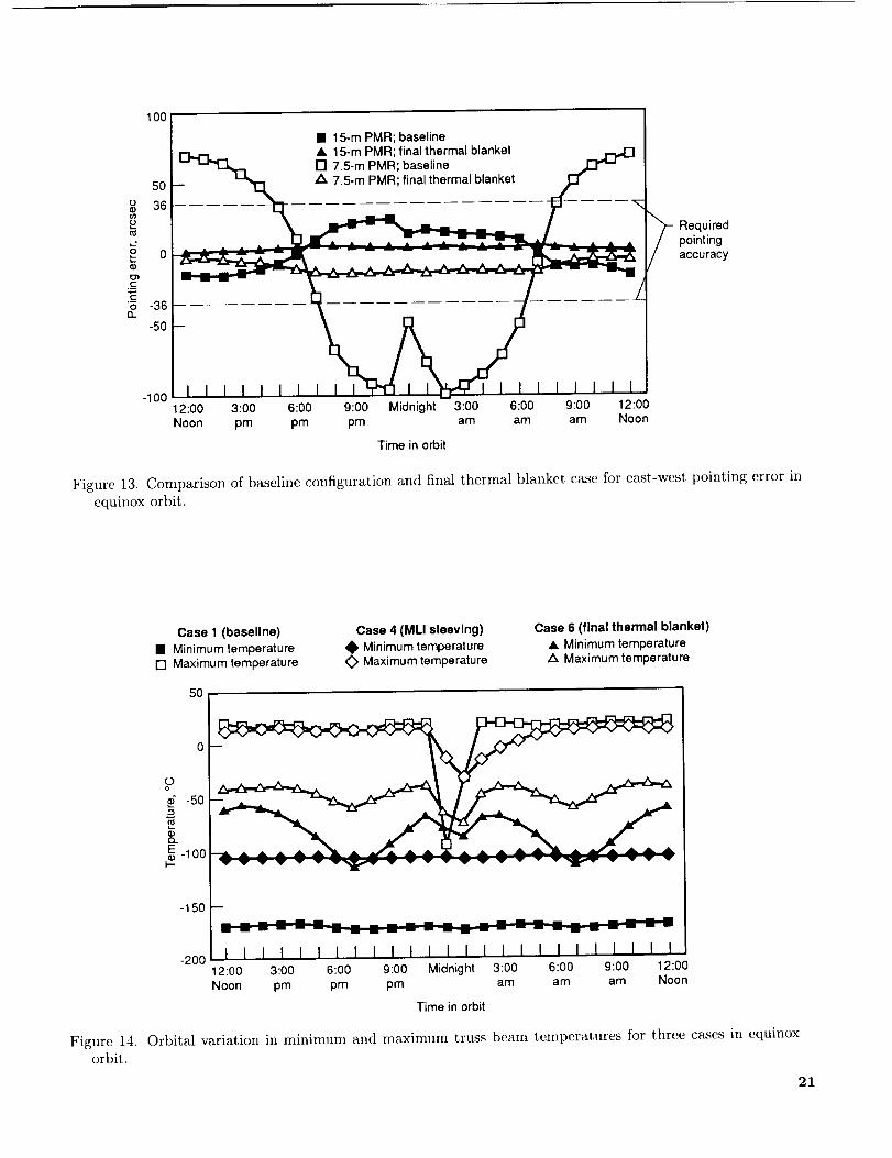
In the equinox orbit the east-west pointing error
of the 15-m PMR ranges from 6 to 2 arcseconds andthat of the 7.5-m PMR ranges from -14 to 3 arc-
seconds. Figure 13 shows the pointing errors of the15-m and 7.5-m PMR's as a function of time in
equinox orbit relative to the baseline pointing errors
and illustrates the tremendous smoothing effect that
the thermal blanket has on pointing error by elimi-
nating internal shadowing. The solstice orbit exhibits
similarly small east-west pointing errors ranging from2 to 5 arcseconds for the 15-m PMR and from -10 to
-2 arcseconds for the 7.5-m PMR. The improvement
8
in the solstice orbit results compared with those of
the baseline configuration further illustrates the ad-
vantageous effect of thermally decoupling the struc-ture from the orbital environment.
Trends in Analytical Results
In the previous section the analytical results ofthe baseline configuration were presented. The re-
sults of each thermal enhancement were presented in
terms of its capability to improve the thermal per-
formance relative to the baseline configuration. The
general trends in performance improvement will now
be demonstrated by comparing the analyzed baseline
configuration (case 1), the MLI sleeving configura-
tion (case 4), and the final thermal blanket configu-
ration (case 6). Specifically, the trends will be iden-
tified with regard to truss temperature and pointing
error profiles. For brevity in describing the trends,
the configurations will be identified by their casenumber as defined in table II. The three cases listed
above were chosen because the analytical results ofthe MLI sleeving configuration and the final thermal
blanket configuration show with clarity the amount
of improvement in thermal performance that is at-
tainable by applying those enhancement techniques
to the baseline configuration. The two surface-coated
configurations are eliminated from this discussion be-
cause of their relative ineffectiveness in improving thethermal performance.
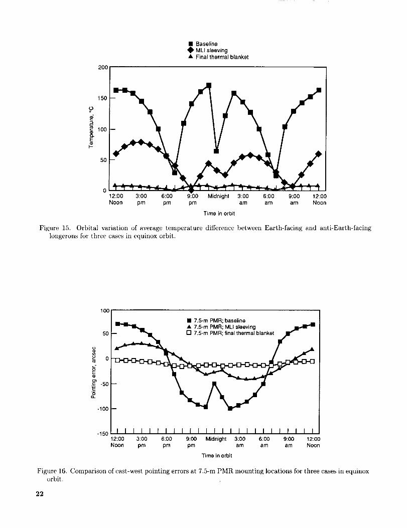
Figure 14 shows the orbital variation in the min-
imum and maximum truss member temperatures for
cases 1, 4, and 6 identified above and illustrates sev-
eral points of interest. The most striking aspect
shown by the curves is that cases 1 and 4 have nearly
constant maximum and minimmn temperatures, ex-cept for the coincident drops in the maximum tem-
perature during the Earth's shadow, whereas the
curves for case 6 track each other with a nearly si-
nusoidal shape. As stated previously, the maximum
temperature correlates to a truss member that is ex-
posed to direct solar flux, and the minimum tem-
perature correlates to a truss member that is com-
pletely shadowed. In cases 1 and 4 there are truss
members that are exposed and/or shadowed for alltimes of the orbit, excluding those in the Earth's
shadow, and therefore exhibit the extreme temper-atures consistently. In case 6, however, the thermalblanket shields all truss members from direct view-
ing of the solar flux and deep space, thereby actingas a buffer between the orbital environment and the
truss. In addition, as the outside surface of the blan-
ket on one side of the truss heats up from direct solarflux exposure, the inside surface radiates thermal en-
ergy to all internal blanket faces and truss members.
The resultof this reradiatingeffectis a moreuni-formdistributionofheatfluxesthroughoutthetrussstructureand,hence,muchlessof a differencebe-tweenthemaximumandminimumtemperatures.
Alsoevidentin figure14is that thedifferencebe-tweentheminimumandmaximumtemperaturesisgreaterfor case1. However,the maximumtemper-aturecurvefor case4 nearlytracesthat of case1.Theratioof solarabsorptivityto thermalemissivity(a/e) inducesthis behaviorby governingthe ratioof incidentsolarenergyabsorbedto thermalenergyemittedbythosetrussmembersthat areexposedtothe Sun. Becausecase1 hasana/e ratioof 1.125and case4 hasan a/e ratio of 1.0, the maximum
temperatures are relatively close. In addition, case 4
has a significantly higher minimum temperature than
case 1. The considerably lower thermal emissivity of
case 4 causes the truss members not exposed to the
Sun to retain much more thermal energy than those
in case 1, thereby maintaining higher minimum tem-
peratures. The temperature differences between the
longerons of opposing sides of the truss structure,
caused by internal shadowing, have been shown to
be the primary cause of east-west pointing error inthe equinox orbit. The trends in how the perfor-
mance enhancements affect these temperature differ-ences are of interest.
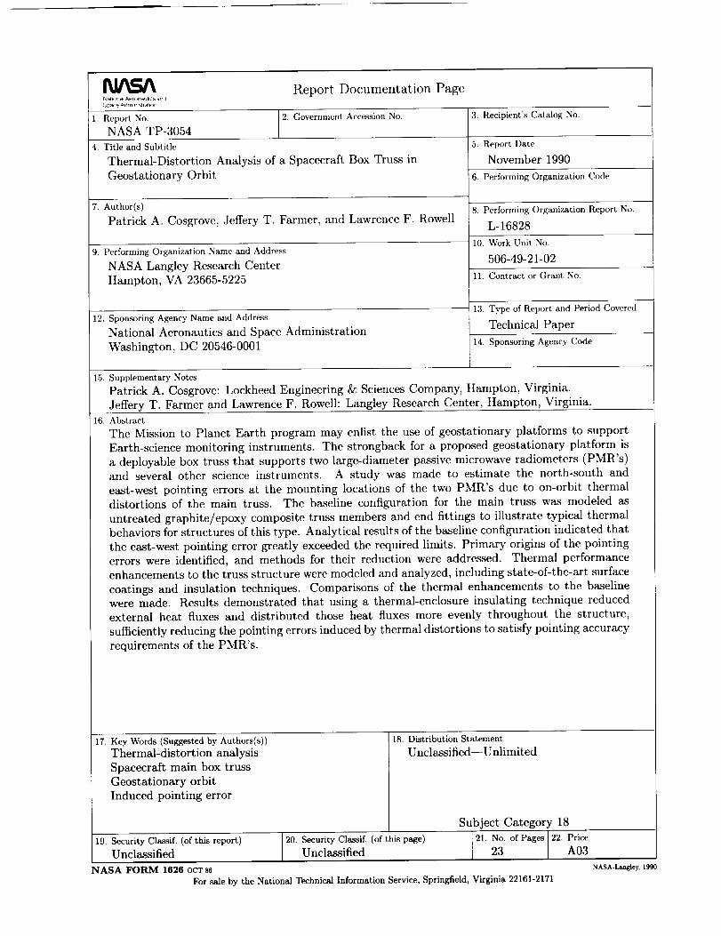
Figure 15 illustrates the orbital variation in the
average temperature differences for the three cases
described above. The maximum temperature differ-
ence between opposing longerons exceeds 170°C for
case 1. The temperature difference is greatly reduced
to around 75°C for case 4, and, again, significantly tobelow 10°C for case 6. The fundamental reasons for
the reduced temperature differences are the same as
those discussed above. Also apparent in figure 15 is
the drop in the temperature difference around localmidnight, when the entire structure is in the Earth's
shadow and, therefore, when all truss members havea common radiative heat sink.
Figure 16 compares the worst-case pointing errors
for cases 1, 4, and 6. By placing both of the perfor-mance enhancement cases on the same scale as the
baseline configuration case, the relative amounts of
pointing improvement that are achievable by apply-ing the respective insulating techniques become more
apparent.
Concluding Remarks
A thermal analysis of the main box truss struc-
ture of a geostationary platform concept was made.
Structural element temperatures were obtained from
a finite-difference analysis for positions throughout
the geostationary orbit and were used to create the
thermal loads for finite-element structural analy-
sis. Thermal and structural analyses were made for
equinox and solstice orbits. Performance results of
the structural analysis were in terms of east-west
and north-south pointing errors at the mounting lo-cations of the two radiometers.
The baseline configuration employs an uncoated
graphite/epoxy composite box truss construction.
This material, although not practical because of the
effects of the space environment on uncoated compos-
ite materials, serves to demonstrate typical thermal
behaviors for this type of truss in a geostationary
orbit. Also, the baseline configuration allows quan-tification of worst-case thermal distortions to which
the performance of alternative thermal design op-
tions can be compared.The worst thermal distortions for the baseline
configuration led to significant east-west pointing er-
rors during the equinox orbit. These east-west point-
ing errors resulted primarily from temperatt_re differ-
ences between the Earth-facing and anti-Earth-facing
truss longerons. The symmetrical design of the main
box truss, combined with 0° declination at equinox,
causes significant internal shadowing of longerons on
the anti-Sun side, thereby greatly diminishing the
solar heating on that side. The maximum east-
west pointing errors for the 15-m and 7.5-m pas-
sive microwave radiometers (PMR's) were 25/-15 and
71/-99 arcseconds, respectively. The 7.5-m PMR fails
to meet the required pointing accuracy of 36 arc-
seconds. Therefore, significant differences in temper-ature and distortions exist between the two sides. In
the solstice orbit analyzed, the incident Sun angle of
23.5 ° eliminated the excessive internal shadowing of
the longerons that was present in the equinox orbit,thereby greatly reducing the temperature differences
between the opposing sides and the resulting east-
west pointing errors. There is a proportionality of
the pointing errors of the 7.5-m and 15-m PMR's to
their distance from the restrained housekeeping and
payload (H/P) modules.
Calculated north-south pointing errors are small
relative to the east-west pointing errors and, unlike
the east-west errors, marginally satisfy the speci-
fied pointing requirements for all configurations ana-
lyzed. The primary causes of the north-south point-
ing errors are unbalanced torsion effects induced by
the thermal distortion of truss diagonals and ba-tons. The imbalances are due to the truss lattice
pattern and the odd number of bays on each side
of the restrained module. Many configuration de-
sign changes exist that would greatly reduce or elim-inate the north-south pointing errors, each of which
requires further study to determine the impact on
other features of the spacecraft design.
9
The thermalcontroloptionsconsideredincludesurfacecoatingsandinsulatingtechniquesandareevaluatedrelativeto thebaselineconfigurationwithrespectto theireffectivenessin reducingtheeast-westpointingerrors. Theapplicationof state-of-the-artsurfacecoatingsto thetrussmembersdecreasesthepointingerror by providingmorefavorableenergybalances.However,theresultingreduceddistortionsremainabovethespecifiederrorlimits. Aninsulatingtechniquethat wrapsindividualtrusselementswithmultilayerinsulation(MLI) resultsin a significantimprovementin pointing performance.However,the east-westpointing errorsremainin excessofthe specifiederrorlimits duringcertainportionsofthe equinoxorbits. An insulatingtechniquethatenclosesthe entiretrusswithin a thermalblanketof aluminizedKaptonsufficientlydecreasespointingerrorssuchthat thespecifiedpointingrequirementsaresatisfied.However,this approachmayincreasethe complexityof deploymentand/or erectionascomparedwith thematerialcoatingorMLI-wrappedapproaches.
Theseresultsindicatethat improvedpointingac-curacyis achievedusingseveralmethods.However,only thosemethodsthat reduceradiativeheatex-changesbetweenthetrussstructureandtheorbitalenvironmentand thosethat fosteruniformdistri-butionof the radiativefluxesthroughoutthe truss
structureareeffectivein reducingpointingerrorsuf-ficientlyto meetthespecifiedpointingrequirementsof this mission.The thermalblanketconfigurationpresentedin this study wassuccessfulin meetingthespecifiedpointingrequirementsfor the7.5-mand15-mPMR's.However,thecomplexitythat thether-mal blanketaddsto the deploymentand/or erec-tion scenarioenlistedfor this geostationaryconceptmustbeconsidered.Othertechniquesintendedtoachievemissionpointingrequirementsmaybeworthyof study,suchasanasymmetricaltrussdesignthatprecludestheoccurrenceof excessiveinternalshad-owingunderanypossibleorbitalconditions.Again,modificationsto theboxtrussdesignunavoidablyre-quireexaminationof their impacton otherdesignfeaturesand characteristics.Anotheroption thatcanbe implementedfor anyconfigurationis to in-corporateactiveon-orbitpointingcorrectionsbasedon thepredictedpointingerrors. In orderto fairlyevaluatethetechniquesavailablefor thermalperfor-manceenhancement,it isnecessaryto considermoreissuesthansimplytheexpectedthermalperformanceof eachoption. Forexample,theon-orbithandling,maintenance,complexity,andlifetimemustbecom-paredto thethermalperformancegainanticipated.
NASALangleyResearchCenterHampton, VA 23665-5225August 23, 1990
10
Appendix
Modeling and Analysis ToolsThe structuralandthermalanalyseswereper-
formedusingasystemofcomputer-aidedengineeringsoftware.ThissoftwareincludesSupertab(forvisualinspectionand modificationof finite-elementmod-elsand postprocessingof results),ThermalModelGenerator(TMG)(forthermalmodelingandanaly-sis),andModelSolution(forlinear,staticstructuralanalysis).A briefdiscussionofthesetoolsfollows,asaddressedin reference2.
Supertab
Supertab is part of the I-DEAS software sys-
tem developed by the Structural Dynamics Research
Corporation (SDRC). It is used to interactively build,
visualize, and modify finite-element models prior tostructural analysis and to visually interrogate the
results of such an analysis. These models are ana-
lyzed in TMG or Model Solution, as discussed be-low; the results (such as temperatures, deflections,
and stresses) are automatically translated back to
Supertab for postprocessing.
Thermal Model Generator
TMG is an integrated thermal analysis tool de-
veloped by MAYA Heat Transfer Technologies Ltd.of Canada that works in conjunction with SDRC's
Supertab to perform complete thermal modeling and
analysis tasks. More specifically, TMG accepts the
finite-element geometric model output from Supertab
and employs an interactive menu-driven input sys-tem to build a complete lumped-parameter (or finite-
difference) thermal model that can be used to esti-mate steady-state or transient element temperatures
for subsequent thermal-structural analysis.
In building this thermal model, TMG performsseveral intermediate functions: it translates finite-
element model data into a surface model for calcula-
tion of radiation heat transfer characteristics and into
a finite-difference thermal network model by calcu-
lating conductive conductances and thermal capaci-
tances; it calculates radiation exchange view factors,
radiative conductances, and orbital heat fluxes (in-
cluding the effects of shadows and reflections) us-
ing techniques based on diffuse enclosure assump-
tions; it uses these radiative couplings and heat fluxes
along with the translated finite-difference model to
calculate steady-state or transient temperature dis-
tributions and heat transfer rates employing thermal
network techniques and various matrix solution al-
gorithms; it maps these temperatures back ontothe finite-element model and translates them into
Supertab for graphical postprocessing and as input
to Model Solution. TMG performs these functions
in an integrated nature, thus automating the entire
process.
Model Solution
Model Solution is the primary numerical solver
for the I-DEAS software package. Its direct connec-
tion with Supertab significantly automates modeling,
analysis, and visualization of results. Its linear static
structural analysis capability used for this study isbased on a finite-element formulation of linearized
structural deformation equations. Inputs include the
finite-element model built in Supertab, a restraint
set or boundary conditions, and the element temper-atures that act to produce structural loads. Model
Solution estimates the displacements of the nodes in
the finite-element model of the reflector strongback
as well as element stresses caused by these loads and
translates them back to Supertab where they can be
graphically examined.
11
References
1. Wahls, Deborah M.; Farmer, Jeffery T.; and Sleight,
David W.: On-Orbit Structural Dynamic Performance
of a 15-Meter Microwave Radiometer Antenna. NASA
TP-3041, 1990.
2. Farmer, Jeffery T.; Wahls, Deborah M.; and Wright,
Robert L.: Thermal-Distortion Analysis of an Antenna
Strongback for Geostationary High-Frequency Microwave
Applications. NASA TP-3016, 1990.
3. Supertab Engineering Analysis Pre- and Post-Processing
User Guide. I-DEAS Level 4, Structural Dynamics Re_
search Corp., 1988.
4. TMG Thermal Model Generator--A Thermal Analy-
sis Computer Program (TMG User's Manual). Revi-
sion 2.2, MAYA Heat Transfer Technologies Ltd., Mon-
treal, Canada, 1988.
5. Supertab Engineering Analysis Model Solution and Op-
timization User Guide. I-DEAS Level 4, Structural Dy-
namics Research Corp., 1988.
6. Pidgeon, David Joseph: A Subsystem Design Study of an
Earth Sciences Geostationary Platform. M.S. Thesis, The
George Washington University, 1989.
7. Agrawal, Brij N.: Design of Geosynchronous Spacecraft.
Prentice-Hall, Inc., c.1986.
8. Hedgepeth, John M.: Accuracy Potentials for Large Space
Antenna Reflectors With Passive Structure. J. Spacecr.
Rockets, vol. 19, no. 3, May June 1982, pp. 211 217. (Also
available as AIAA-82-4136.)
9. Dursch, H.; and Hendricks, C.: Development of Composite
Tube Protective Coatings. NASA CR,178116, 1986.
12
15-m passive microwaveradiometer (PMR)
Earth
Payloadmodule
Housekeepingmodule
passive microwaveradiometer (PMR)
blarsail
Other scienceinstruments Platform main bus truss
Figure 1. Geostationary Earth-science platform.
13
©
©
..=
14
N
Orbit path traversing
Earth's shadow -_ /
_- Earth's shadow
Collimatedsolar flux
/ "--,Orbitplane = Equatorial plane
(a) Equinox orientation.
Orbit plane that never
_ Earth)
/__adow
(b) Summer solstice orientation.
Collimatedsolar flux
%
_it plane = Equatorial plane
Figure 3. Earth's shadow at equinox and solstice.
15
c
-oE
u.._l
c- c
r-- _.-- _
#s_ °r_ 4
"I_.
___ E"-" s"
•_w_C: '_ _ •_(!_
_5_ >
©©
©
.._>
-d
16
• Anti-Earth-facing Iongerons_I_ Earth-facing Iongerons
50
0
? -5o
_--100
-150
-2O012:00 3:00 6:00 9:00 Midnight 3:00 6:00 9:00 12:00Noon pm pm pm am am am Noon
Time in orbit
Figure 5. Orbital variation of average temperatures of longerons for baseline configuration in equinox orbit,.
• Anti-Earth-facing Iongerons_), Earth-facing Iongerons
2O
'i-10
°O -20
L -30
E -40
-50
1,012:00 3:00 6:00 9:00 Midnight 3:00 6:00 9:00 12:00Noon pm pm pm am am am Noon
Time in orbit
Figure 6. Orbital variation of average temperatures of longerons for baseline configuration in solstice orbit.
IT
(J
t0
o0_
E2
c:
On
• 15-m PMR mounting location
100 • 7.5-m PMR mounting location
5O
36
0
-36
-50
-10012:00 3:00 6:00 9:00 Midnight 3:00 6:00 9:00 12:00Noon pm pm pm am am am Noon
Time in orbit
Requiredpointingaccuracy
Figure 7. East-west pointing error at PMR mounting locations as a function of equinox orbital position.
• Baseline configuration• Adjacent bay nodes restrained
5_,,,A .,= ..... "- A " "= A"=vv T v,,--_ A .... i,- ,_p,4p_ IV _ _ v V _ _ _ _ V v V _ v
0
g-5
g
_ -10E
-15
-202:0 3:00 6:00 9:00 3:00 6:00 9:00 12:00
.EI3.
MidnightNoon pm pm pm am am am Noon
Time in orbit
Figure 8. Comparison of north-south pointing error of 7.5-m PMR with nodal restraints added to baseline
configuration in equinox orbit.
18
• 15-m PMR mounting location
7.5-m PMR mounting location
10
5
03
g,,.- 0
-5
-10t2:00 3:00 6:00 9:00 Midnight 3:00 6:00 9:00 12:00Noon pm pm pm am am am Noon
Time in orbit
Figure 9. East-west pointing error at PMR mounting locations for baseline configuration in solstice orbit.
100• 15-m PMR; baseline
15-m PMR; high WE• 15-m PMR; low _¢
I [] 7.5-m PMR; baseline _E];_ I
50 I--- _ 0 7.5-m PMR; high eU¢ _ I
L.?
$ 0 uiredReq$ pointing._ accuracyE
__ -36 ............
-50
-10012:00 3:00 6:00 9:00 Midnight 3:00 6:00 9:00 12:00Noon pm pm pm am am am Noon
Time in orbit
Figure 10. Comparison of baseline configuration and surface-coating cases for east-west pointing error in
equinox orbit.
19
1°°I • 15-m PMR; baseline
i_ • 15-m PMR; MLI sleeving ,-,.Z3 I[] 7.5-m PMR; baseline . _ -- I
12:00 3:00 6:00 9:00 Midnight 3:00 6:00 9:00 12:00Noon pm pm pm am am am Noon
50
o 36O3
2 0h..
r-
r-
6 -3613_
-50
-100
Time in orbit
Requiredpointingaccuracy
Figure 11. Comparison of baseline configuration and MLI sleeving case for east-west pointing error in equinox
orbit.
Figure 12.
orbit.
• Anti-Earth-facing Iongerons• Earth-facing Iongerons
-40
-50
-60
?d -70
. 80
-90
-100
-11012:00 3:00 6:00 9:00 Midnight 3:00 6:00 9:00 12:00Noon pm pm pm am am am Noon
Time.in orbit
Orbital variation of average temperatures of longerons for final thermal blanket case in equinox
2O
100
50
36.o
00_
E
-36-50
-100
• 15-m PMR; baseline
El--r-L_ A 15-m PMR; final thermal blanket
_____ r'17.5-mPMR;baseline _____
12:00 3:00 6:00 9:00 Midnight 3:00 6:00 9:00 12:00Noon pm pm pm am am am Noon
Time in orbit
Requiredpointingaccuracy
Figure 13. Comparison of baseline configuration and final thermal blanket case for east-west pointing error in
equinox orbit.
Case 1 (baseline)
• Minimum temperature[] Maximum temperature
Case 4 (MLI sleeving)
_, Minimum temperatureMaximum temperature
Case 6 (final thermal blanket)
• Minimum temperatureZ_. Maximum temperature
5O
0
" -50
E -100I--
-150
-200
m
m m m m a m -- m m -- __ m m -- -- m --
i m i m m i _ i i m _ mmm i MN mm m n i m
I I i I I ) I I I I ) ) I ) I I i I ) I I ) I J )
2:00 3:00 6:00 9:00 Midnight 3:00 6:00 9:00 12:00
Noon pm pm pm am am am Noon
Time in orbit
Figure 14. Orbital variation in minimum and maximum truss beam temperatures for three cases in equinox
orbit.
21
• Baseline_l, MLI sleeving• Final thermal blanket
2O0
150
P
_ t00
F-
12:00 3:00 6:00 9:00 Midnight 3:00 6:00 9:00 12:00Noon pm pm pm am am am Noon
Time in orbit
Figure 15. Orbital variation of average temperature difference between Earth-facing and anti-Earth-facing
longerons for three cases in equinox orbit.
Figure 16.
orbit.
l°°1 I_ • 7.5-m PMR; baseline
I _ .7.5-m PMR; MLI sleeving _ I50 .- ""
o
._ -50
2
-100
-15012:00 3:00 6:00 9:00 Midnight 3:00 6:00 9:00 12:00Noon pm pm pm am am am Noon
Time in orbit
Comparison of east-west pointing errors at 7.5-m PMR mounting locations for three cases in equinox
22


Report Documentation PageNallonal Aeronaul_cs and
j Soace Adm_n,stral_on
,1. Report No.
NASA TP-3054
2. Government Accession No.
4. Title and Subtitle
Thermal-Distortion Analysis of a Spacecraft Box Truss in
Geostationary Orbit
7. Author(s)
Patrick A. Cosgrove, Jeffery T. Farmer, and Lawrence F. Rowell
9. Performing Organization Name and Address
NASA Langley Research Center
Hampton, VA 23665-5225
12. Sponsoring Agency Name and Address
National Aeronautics and Space Administration
Washington, DC 20546-0001
15. Supplementary Notes
3. Recipient's Catalog No.
5. Report Date
November 1990
6. Performing Organization Code
-_ Performing Organization Report No.
L-16828
10. Work Unit No.
506-49-21-02
11. Contract or Grant No.
13. Type of Report and Period Covered
Technical Paper
14. Sponsoring Agency Code
Patrick A. Cosgrove: Lockheed Engineering & Sciences Company, Hampton, Virginia.
Jeffery T. Farmer and Lawrence F. Rowell: Langley Research Center, Hampton, Virginia.
16. Abstract
The Mission to Planet Earth program may enlist the use of geostationary platforms to support
Earth-science monitoring instruments. The strongback for a proposed geostationary platform is
a deployable box truss that supports two large-diameter passive microwave radiometers (PMR's)and several other science instruments. A study was made to estimate the north-south and
east-west pointing errors at the mounting locations of the two PMR's due to on-orbit thermal
distortions of the main truss. The baseline configuration for the main truss was modeled as
untreated graphite/epoxy composite truss members and end fittings to illustrate typical thermalbehaviors for structures of this type. Analytical results of the baseline configuration indicated that
the east-west pointing error greatly exceeded the required limits. Primary origins of the pointing
errors were identified, and methods for their reduction were addressed. Thermal performanceenhancements to the truss structure were modeled and analyzed, including state-of-the-art surface
coatings and insulation techniques. Comparisons of the thermal enhancements to the baselinewere made. Results demonstrated that using a thermal-enclosure insulating technique reduced
external heat fluxes and distributed those heat fluxes more evenly throughout the structure,
sufficiently reducing the pointing errors induced by thermal distortions to satisfy pointing accuracy
requirements of the PMR's.
17. Key Words (Suggested by Authors(s))
Thermal-distortion analysis
Spacecraft main box truss
Geostationary orbit
Induced pointing error
19. Security Classif. (of this report)
18. Distribution Statement
Unclassified--Unlimited
Subject Category 18
20. Security Classif. (of this page) 21, No. of Pages 1 22. PriceUnclassified 23 1 A03Unclassified
NASA FORM 1626 oct 86
For sale by the National Technical Information Service, Springfield, Virginia 22161-2171
NASA-Langley, 1.990


NationalA_utics and *:_ : _: --
__ Space Administration _Code NTT-4 - -
- Washington-D.C. i: -_ ;_20546-0001 _ :- ....
Otr_iat Bm_ess " -
Penalty for Private Use. 5300
_ -r
- -- 2
" . [ I ]]I "
Z
BUEK RATEPOSTAGE& FEES PAID
NASAPermit No. G-27
POSTMASTER: If Undetiv_bte (Section ISS
Postal Msnmd) Do Not Retm
]
• ._ . _
- . . _ -
. r
=
"Z" "
J


![RADIOMETERS MEASUREMENT ON - NIST · 2012-10-04 · Cobientz] StellarRadiationMeasurements 617 deflection,skyhazy) TheratiooftheradiationsVega-f-Altair=3.7,whichisatvariancewiththeresultsobtainedinthepresent](https://img.pdfslide.us/doc/110x75/5e60795abc9bf23ac13e7c61/radiometers-measurement-on-nist-2012-10-04-cobientz-stellarradiationmeasurements.jpg)