Embed Size (px)
Citation preview

PandID®B.V. - t: +31 174 280 371 - f: +31 174 280 853 - i: www.pandid.nl - e: [email protected]

Pressure Relief ValvesValvole di Sicurezza

SERIE/Series 30000
Indice • Index
Caratteristiche generali pag. 2General characteristics
Distinta Materiali pag. 4Material List
Accessori pag. 5Accessories
Informazioni Tecniche pag. 7Technical Information
Composizione codice pag. 9Coding System
Connessioni pag. 10Dimensions
Guida per la scelta delle valvole di sicurezza pag. 24Guide for the selection of pressure relief valves
Certificati pag. 25Certificates
1

SERIE/Series 300002
General characteristicsDesign, calculation and selection, manufacturing and testing are based on the following standards:Calculation EN ISO 4126-1 API RP 520 - ISPESLGeneral Design API - 526Materials ASTM
NACE MR0175 ISO 15156Tightness API STANDARD - 527Homologated discharge coeff. ISPESL (Italy)
Additionally to the standardized version, described in this catalogue, which relate to the standardized version these models can be manufactured in other materials and flange types and can be equipped with many accessories.
OverpressureThe following overpressures are required to obtain the maximum discharge lift:
10% for gases and vapours25% for liquids0,2 bar minimum overpressure
ClosureThe tolerance clousure value is between 7% and 10% of the set pressure. This value depends on the process status and on the fluid type.
Pressure RegulationThe spring set pressure regulation range is:± 5% for pressures above 17 bar
Discharge CoefficientThe discharge coefficient for gases and vapours has been homologated by ISPESL (Higher Institute for Health and Safety in the Workplace) in Italy.K = 0,94 for gases and vapoursK = 0,6 for liquids
Minimum Set PressureThe minimum set pressure value is 0,5 bar.
Connection FlangesThe valves can be supplied with connection flanges as per ANSI B 16.5, DIN standards, or other standards specified in the order.
Caratteristiche generaliIl disegno, il calcolo e la selezione così come la produzione e il collaudo si basano sui seguenti standards:Calcolo EN ISO 4126-1 API RP 520 - ISPESLDisegno generale API 526Materiali ASTM
NACE MR0175 ISO 15156Controllo tenuta API STANDARD - 527Coefficiente di efflusso omologato ISPESL (Italia)
Oltre alle descrizioni contenute nel catalogo, che si riferiscono alla versione standard, questi modelli possono essere prodotti in altri materiali e tipi di flangia e possono essere dotati di numerosi accessori.
SovrappressionePer ottenere l’alzata massima di scarico, occorre la seguente sovrappressione:
10% per gas e vapori25% per liquidi0,2 bar sovrappressione minima
ChiusuraIl valore di chiusura è compreso tra il 7% e il 10% della pressione di taratura. Il valore dipende dallo stato del processo e dal tipo di fluido.
Regolazione della pressioneIl campo di regolazione della molla é:± 5% per pressioni superiori a 17 bar
Coefficiente di efflussoIl coefficiente di efflusso per gas e vapori è stato omologato dall’ISPESL (Istituto Superiore per la Prevenzione e la Sicurezza del Lavoro) in Italia.K = 0,94 per gas e vaporiK = 0,6 per liquidi
Pressione di taratura minimaIl valore minimo della pressione di taratura è di 0,5 bar.
Flange di connessioneLe valvole possono essere dotate di flange di connessione in base agli standards ANSI B 16.5, DIN, o altro standard specificato nell’ordine.

SERIE/Series 30000 3
Le valvole di sicurezza Serie 30000 sono state progettate per l’impiego su vapori, fluidi gassosi e fluidi liquidi. Sono del tipo a boccaglio pieno, ad alzata totale e con carico diretto a molla. Gli orifizi, le dimensioni, il tipo di attacco, i materiali ed i limiti d’impiego sono rispondenti alla normativa API 526 ed omologati dalla ISPESL.
The 30000 Series pressure relief valves have been designed for steam, gaseous and liquid fluids applications. The valves are of full-nozzle, full lift and spring loaded type.Orifices, dimensions, connections, materials and application limits are in accordance with API 526 Standard and are homologated by ISPESL.
CaratteristicheIl corpo della valvola è fuso con spessori conformi a quanto specificato nella norma ASME B 16.34.L’ampia cavità interna del corpo assicura una agevole espansione del fluido scaricato e ridotte contropressioni generate dallo scarico.Sono disponibili, su richiesta, alcuni accessori, quali: leva di sollevamento, vite di blocco, soffietto di isolamento e bilanciamento, finecorsa elettrico, per segnalazione apertura valvola.Le valvole con soffietto mantengono, tranne il gruppo guida-soffietto-portaotturatore, tutti i particolari utilizzati nelle valvole convenzionali. ll soffietto è saldato alla guida ed al portaotturatore in modo da garantire la perfetta tenuta della contropressione; ogni saldatura è controllata con macchina rilevatrice di elio.La sede di tenuta è piana, del tipo “metallo su metallo”, con riporto di stellite su richiesta.
Oltre agli attacchi flangiati secondo la normativa ANSI, sono disponibili attacchi flangiati secondo UNI, DIN, AFNOR, ecc.In caso d’utilizzo delle valvole per fluidi molto viscosi è disponibile un’esecuzione con camicia di riscaldamento (è consigliato l’utilizzo insieme con un soffietto d’isolamento, onde evitare inceppamenti dell’accoppiamento guida-portaotturatore). Le valvole sono dotate ognuna di una targhetta in acciaio inossidabile con riportati i dati caratteristici e la taratura della valvola stessa.Tutte le valvole sono accompagnate da una dichiarazione di costruzione che riporta le caratteristiche delle valvole e garantisce i dati di collaudo. Su richiesta viene fornito un verbale di collaudo rilasciato da un ente ufficiale quale: ISPESL, DNV, RINA, BUREAU VERITAS, LLOYD’S REGISTER, TÜV, ecc.
TaraturaTutte le valvole vengono tarate al banco con contropressione atmosferica. Se è prevista una contropressione costante allo scarico, la pressione di taratura viene ridotta del valore della contropressione in modo da avere, in esercizio, l’apertura della valvola alla pressione riportata sulla targa. È opportuno, però, che la contropressione non superi il 35% della pressione di taratura e, comunque, il valore massimo di 28 bar. Il campo di regolazione della molla è di ± 5% della pressione di taratura. L’errore massimo di taratura è inferiore al 3% per pressioni fino a 21 bar, con un minimo di 0,2 bar; è inferiore a 0,7 bar fino a 70 bar, oltre i 70 bar è inferiore a 1%. La prova di tenuta viene effettuata secondo la norma API STD 527: con aria sotto un battente d’acqua, ad una pressione pari al 90% della pressione di taratura; le perdite ammesse sono inferiori ai limiti fissati dalla norma API STD 527. Valvole con perdite nulle possono essere fornite su richiesta.
DimensionamentoIl dimensionamento delle valvole di sicurezza, utilizzate per la protezione di recipienti contenenti gas, vapori o liquidi, viene effettuato secondo le principali normative nazionali ed internazionali.
CharacteristicsThe valve body is a casting with thickness in compliance with standard ASME B 16.34.The wide internal hollow of the body assures an easy expansion of the discharging fluid and a minimum back pressure due to discharge.On request, the valves are also available with some accessories such as:lifting lever, test gag, insulating and balancing bellows, electric limit switch for opening-valve signal. Valves with bellows mantain all the parts provided in the standard ones, except for the guide-bellows-disc holder group. The bellows is welded to the guide and to the disc holder in order to guarantee a perfect back pressure tighness; all weldings are inspected with helium-detector machine.The valve seat is plane, metal-to-metal type, with stellited surfacing upon request.
In addition to flanged connections according to ANSI Standards, valves are available with flanged connections according to UNI, DIN, AFNOR Standards etc. In case of valves used for very viscous fluids, a heating jacketed version is available (the use of an insulation bellows is suggested in order to avoid guide-actuator holder coupling interruptions).Every valve is furnished with a stainless steel plate specifying the characteristic data and the setting pressure of the valve itself.All the valves are provided with a construction declaration stating features of the valves and guaranteeing test results.On customer’s request a test report is available, and it is issued by an official organisation such as ISPESL, DNV, RINA, BUREAU VERITAS, LLOYD’S REGISTER, TÜV, etc.
SettingOn test bench all valves are set with an atmospheric back pressure.In presence of back pressure at discharge, set pressure is reduced of the needed value in order to get in service a valve opening at the pressure specified on the plate. However, it is advisable not to let the back pressure exceed 35% of the set pressure and maximum valve of 28 bar. The adjustment range of the spring is ± 5% of the setting pressure.The maximum setting error is less than 3% for setting pressure up to 21 bar, with a minimum of 0,2 bar, is less than 0,7 bar up to 70 bar, is less than 1% for pressure over 70 bar.The tightness test is performed according to the standard API STD 527: with air under a water head at a pressure corresponding to 90% of the set pressure; the permissible leakages are less than the ones fixed in API STD 527 table. On request, valves with no leakages can be provided.
SizingSizing of the pressure relief valves used for the protection of gas, liquid and steam containers are in accordance with the main national and international Standards.
SERIE/Series 300004
Limiti di temperatura / Temperature Limits
Classe Materiali / Material Codes
-29°÷232°C -29°÷426°C -29°÷538°C -45°÷232°C -101°÷232°C -196°÷350°C -268°÷350°C
16 (1) 1L (2) W0 (2) L4 (1) L3 (2) 60 (1) 6L (2)
Parti Parts
PO
S /
ITE
M
(1) Disponibile con boccaglio stellitato / Available with stellited seat nozzle(2) Disponibile con boccaglio ed otturatore stellitati / Available with stellited nozzle seat and stellited disc
AISI 316L AISI 316L AISI 316 AISI 316L AISI 316L AISI 316L AISI 316L
17 - 4PH AISI 316L AISI 316 17 - 4PH AISI 316L 17 - 4 PH AISI 316L
17 - 4PH 17 - 4PH AISI 316 17 - 4PH AISI 316L 17 - 4PH AISI 316L
AISI 316L AISI 316L AISI 316 AISI 316L AISI 316L AISI 316L AISI 316L
AISI 316L AISI 316L AISI 316L AISI 316L AISI 316L AISI 316L AISI 316L
AISI 316 AISI 316 AISI 316 AISI 316 AISI 316 AISI 316 AISI 316
A216WCB A216WCB A217WC6 A352LCB A352LC3 A351CF3M A351CF3M
AISI 303 AISI 303 AISI 303 AISI 303 AISI 303 AISI 303 AISI 303
Carbon steel Carbon steel Carbon steel Carbon steel Carbon steel Carbon steel Carbon steel
AISI 431 AISI 431 AISI 431 AISI 431 AISI 431 AISI 431 AISI 431
Carbon steel Carbon steel Carbon steel Carbon steel Carbon steel AISI 316L AISI 316L
AISI 316L AISI 316L AISI 316L AISI 316L AISI 316L AISI 316L AISI 316L
Carbon steel Tung. steel Stainless steel
A216WCB A216WCB A217WC6 A352LCB A352LC3 A351CF3M A351CF3M
AISI 304 AISI 304 AISI 304 AISI 304 AISI 304 AISI 304 AISI 304
AISI 303 AISI 303 AISI 303 AISI 303 AISI 303 AISI 303 AISI 303
AISI 304 AISI 304 AISI 304 AISI 304 AISI 304 AISI 304 AISI 304
Aram. Fiber Aram. Fiber Aram. Fiber Aram. Fiber Aram. Fiber Aram. Fiber Aram. Fiber
Aluminium Aluminium AISI 304 Aluminium Aluminium AISI 304 AISI 304
Aram. Fiber Aram. Fiber Aram. Fiber Aram. Fiber Aram. Fiber Aram. Fiber Aram. Fiber
FPM Rubber FPM Rubber – FPM Rubber – FPM Rubber –
AISI 304 AISI 304 AISI 304 AISI 304 AISI 304 AISI 304 AISI 304
AISI 304 AISI 304 AISI 304 AISI 304 AISI 304 AISI 304 AISI 304
AISI 304 AISI 304 AISI 304 AISI 304 AISI 304 AISI 304 AISI 304
AISI 431 AISI 431 AISI 431 AISI 431 AISI 431 AISI 431 AISI 431
Carbon steel Carbon steel Carbon steel Carbon steel Carbon steel Carbon steel Carbon steel
AISI 304 AISI 304 AISI 304 AISI 304 AISI 304 AISI 304 AISI 304
17- 4PH 17- 4PH 17- 4PH 17- 4PH 17- 4PH 17- 4PH 17- 4PH
PTFE PTFE PTFE PTFE PTFE PTFE PTFE
AISI 316L AISI 316L AISI 316L AISI 316L AISI 316L AISI 316L AISI 316L
AISI 431 AISI 431 AISI 431 AISI 431 AISI 431 AISI 431 AISI 431
AISI 316L AISI 316L AISI 316L AISI 316L AISI 316L AISI 316L AISI 316L
AISI 304 AISI 304 AISI 304 AISI 304 AISI 304 AISI 304 AISI 304
AISI 304 AISI 304 AISI 304 AISI 304 AISI 304 AISI 304 AISI 304
AISI 304 AISI 304 AISI 304 AISI 304 AISI 304 AISI 304 AISI 304
AISI 304 AISI 304 AISI 304 AISI 304 AISI 304 AISI 304 AISI 304
Stainless steel Stainless steel Stainless steel Stainless steel Stainless steel Stainless steel Stainless steel
Stainless steel Stainless steel Stainless steel Stainless steel Stainless steel Stainless steel Stainless steel
A216WCB A216WCB A217WC6 A352LCB A352LC3 A351CF3M A351CF3M
AISI 304 AISI 304 AISI 304 AISI 304 AISI 304 AISI 304 AISI 304
1 BOCCAGLIO / Nozzle
2 OTTURATORE / Disc
3 PORTAOTTURATORE / Disc-holder
4 GUIDA / Guide
5 ANELLO BLOWDOWN / Blowdown ring
6 ANELLO / Ring
7 CORPO / Body
8 VITE BLOWDOWN / Blowdown screw
9 GUIDA MOLLA / Spring washer
10 VITE DI TARATURA / Adjusting screw
11 CAPPELLO / Cap
12 STELO / Stem
13 MOLLA / Spring
14 COPERCHIO / Bonnet
15 VITE / Screw
16 CONTRODADO / Lock nut
17 GUARNIZIONE / Gasket
18 GUARNIZIONE / Gasket
19 GUARNIZIONE / Gasket
20 GUARNIZIONE / Gasket
21 GUARNIZIONE / Gasket
22 TAPPO / Plug
23 VITE / Screw
24 SPINA / Pin
25 PREMISTOPPA / Ring nut
26 LEVA / Lever
27 DADO LEVA / Lock nut
28 ALBERO LEVA / Lever shaft
29 ANELLO BADERNA / Packing ring
30 FORCELLA / Fork
33 DISCO LEVA / Lever disc
35 SOFFIETTO / Bellows
36 DISTANZIALE / Spacer
37 VITE / Screw
38 RONDELLA / Washer
39 SPINA / Pin
40 SPINA / Pin
41 PRIGIONIERO / Stud bolt
42 CAPPELLO LEVA / Lever cap
43 DADO / Nut
Distinta Materiali / Material List

SERIE/Series 30000 5
22
Soffietto di bilanciamento • Balanced bellowsTipo standard • Standard type
12
15
4
24
16
11
10
14
5
23
8
7
3
6
Leva di sollevamento aperta• Regular lifting lever
26
39
4042 41 43 27 33 28
1
17
18
9
13
20
2
19
21
Parti di ricambio consigliateRecommended spare parts
Accessori • Accessories
Leva di sollevamento con premistoppa • Packed lifting lever
25 38 37 26
29
36
28
30
35

SERIE/Series 300006
Sede soffice • Soft seat Coperchio aperto • Open bonnet
Vite di blocco • Test gag Camicia di riscaldamento • Heating jacket
Accessori • Accessories

SERIE/Series 30000 7
Area dell’orifizio A [cm2] Orifice area
Portata W [kg/h] Flow rate
Portata liquida Q [m3/h] Liquid discharge flow
Pressione di taratura P [bar] Set pressure
Pressione di scarico (pressione di taratura + sovrappressione + 1,013) P1 [bar a] Discharge pressure (set pressure + overpressure + 1,013)
Contropressione P2 [bar a] Back pressure
Temperatura di scarico T [K] Relieving temperature
Fattore di compressibilità a P1 e T (usare 1 se sconosciuto) Z [n°] Compressibility factor at P1 and T (use 1 if unknow)
Peso molecolare M [kg/Kmol] Molecular weight
Coefficiente di espansione in funzione di (X) C [n°] Expansion coefficient as function of (X)
Rapporto calori specifici cp/cv (usare X = 1,001 se sconosciuto) X [n°] Specific heats ratio cp/cv (use X = 1,001 if unknow)
Volume specifico del vapore a P1 e T v1 [m3/kg] Vapour specific volume at P1 and T
Densità relativa del liquido a P1 e T G [kg/dm3] Liquid specific gravity at P1 and Ts
Pressione critica Pc [bar a] Critical pressure
Coefficiente di efflusso K [n°] Discharge coefficient
Coefficiente di correzione per basse tarature di valvole convenzionali se P2 > PC (gas e vapori) K1 [n°] Correction coefficient by low settings for conventional valves if P2 > PC (gases and vapours)
Coefficiente di correzione per liquidi viscosi Kv [n°] Correction coefficient for viscous liquids
Coefficiente di correzione per sovrapressione diversa da 25% Kp [n°] Correction coefficient due to overpressure different to 25%
0,6 per S = 10% 0,8 per S = 15% 1 per S = 25% 0,6 for S = 10% 0,8 for S = 15% 1 for S = 25%
Informazioni Tecniche • Technical Information
Formule di calcolo per l’area dell’orifizioLe formule seguenti servono a determinare l’area minima che l’orifizio della valvola di sicurezza dovrebbe avere per scaricare il flusso di liquido richiesto.
Formulas for the calculation of orifice areaThe following formulas determine the minimum area that the orifice of the pressure relief valve should have in order to discharge the required fluid flow.
Discharge coefficient (K) for 30000 series pressurerelief valves:
Gases and Vapours K = 0,94Liquids K = 0,6
Coefficiente di efflusso (K) per valvole di sicurezzamodello 30000:
Gas e Vapori K = 0,94Liquidi K = 0,6
Formule derivate da API-520 Raccolta “E”- ISPESL Formulas result from API-520 Collection “E”- ISPESL
( )2
X+1
XX-1
Pressione critica / Critical pressure Pc = P1
Gas e Vapori / Gases and Vapours A =0,9 · 394,9 · C · P1 · K · K1 ·
W Z T
M
Vapore acqueo / Steam A =0,9 · 113,8 · C · K · K1 ·
W v1
P1
Liquidi / Liquids A =5,091 · K · Kp · Kv
W
(P1-P2) GA =
5,091 · K · Kp · Kv ·
Q
(P1-P2)
G
;

SERIE/Series 300008
Informazioni Tecniche • Technical Information
Formula del coefficiente di correzione K1 • Formula of the correction coefficient K1
Coefficiente di correzione per contropressione per valvole convenzionali K1 (gas e vapori)Correction coefficient by back pressure for conventional valves K1, (gases and vapours)
Coefficiente correttivo per liquidi viscosi KV • Corretion coefficient for viscous liquids KV
P2
P1 P1
2X
(X-1)-· [( )
P2
K1=C
( ) ]X+12
X X
Questo grafico permette di calcolare il coefficiente per liquidi molto viscosi, in funzione della viscosità stessa, del flusso di scarico e dell’orifizio di entrata.
This chart allows to calculate the coefficient for very viscous liquids, as function of the viscosity itself, the discharge flow and the inlet orifice.
Viscosità dinamica µ [c P ] Dynamic viscosity of the fluid
Area orifizio immediatamente superiore a quello calcolato con Kv=1 A [cm2 ] Orifice area directly higher than the one calculated with Kv=1
R =31314 · Q · G
µ · A
0,3
101 102 103 104 105
0,4
0,5
0,6
0,7
0,8
0,9
1,0
R= Reynold’s Number
Kv=
Vis
cosi
ty C
orre
ctio
n Fa
ctor

SERIE/Series 30000 9
Composizione codice • Coding system
3WW - XX Y - ZZClasse Materiali (due cifre) • Material class code (two digits)vedere 'elenco Materiali' • see 'Material list'
Accessori (una cifra) • Accessories (one digit)vedere 'elenco Accessori' • see 'Accessories list'
Tipo (due cifre) • Type (two digits)vedere nelle tabelle 'Connessioni' • see code on 'Connections' tables
Serie (tre cifre) • Series (three digits)310/300 standard31V/30V servizio vapore, coperchio aperto • steam service, open bonnet31P/30P pilotate • pilot operated31R/30R sede soffice • soft seat
Elenco Accessori • Accessories List0 Tipo Base (Finitura RF) • Base Type (RF Faced)1 Tipo Base + Leva • Base Type + Lever2 Tipo Base + Soffietto • Base Type + Bellows3 Tipo Base + Vite Di Blocco • Base Type + Test Gag4 Tipo Base + Camicia Di Riscaldamento • Base Type + Heating Jacket5 Tipo RJ Base • RJ Base TypeJ Tipo RJ Base + Leva • RJ Base Type + Lever6 Tipo RJ Base + Soffietto • RJ Base Type + Bellows7 Tipo RJ Base + Vite Di Blocco • RJ Base Type + Test Gag8 Tipo RJ Base + Camicia Di Riscaldamento • RJ Base Type + Heating Jacket9 Tipo Base + Leva + Soffietto • Base Type + Lever + BellowsA Tipo RJ Base + Leva + Soffietto • RJ Base Type + Lever + BellowsB Tipo Base + Soffietto + Camicia Di Riscaldamento • Base Type + Bellows + Heating JacketC Tipo RJ Base + Soffietto + Camicia Di Riscaldamento • RJ Base Type + Bellows + Heating JacketD Tipo Base + Soffietto + Vite Di Blocco • Base Type + Bellows + Test GagE Tipo RJ Base + Soffietto + Vite Di Blocco • RJ Base Type + Bellows + Test GagF Tipo Base + Leva + Vite Di Blocco • Base Type + Lever + Test GagG Tipo RJ Base + Leva + Vite Di Blocco • RJ Base Type + Lever + Test GagH Tipo Base + Leva + Soffietto + Vite Di Blocco • Base Type + Lever + Bellows + Test GagK Tipo RJ Base + Leva + Soffietto + Vite Di Blocco • RJ Base Type + Lever + Bellows + Test GagL Tipo Base + Sede Soffice • Base Type + Soft SeatM Tipo RJ Base + Sede Soffice • RJ Base Type + Soft Seat
Per altri accessori contattare i nostri Uffici Commerciale/Ufficio TecnicoFor other accessories contact our Sales Department/Technical Department
Diametro Diameter
mm
D 10.0 0.785 0.121 1.45 2.5E 13.3 1.389 0.215 2.60 3.1F 16.6 2.164 0.335 3.87 4.0G 21.2 3.530 0.547 4.83 6.2H 26.5 5.515 0.854 6.88 9.8J 34.0 9.079 1.407 11.1 11K 40.6 12.94 2.006 15.6 13L 50.6 20.10 3.116 23.9 16M 56.8 25.33 3.927 30.3 19N 62.4 30.58 4.740 35.8 20P 75.7 45.00 6.976 53.0 24Q 99.6 77.91 12.07 90.5 33R 119.8 112.7 17.47 127.4 40T 152.8 183.3 28.42 205.1 50U 180 254.4 39.43 277.5 57
Tipo Type
Area Area SedeSeat Area
cm2
AlzataLiftmmcm2 sq.in.

SERIE/Series 3000010
D1
D2
D3
D4
D5
D7
ORIFICE
Dø 10 mm0.785 cm2
(0,121 sq.in.)
1” 2” 19 19 19 19 12 5 — 10 19 115 105 370 420 15
150 # 150 # 1” 2”
42 49 51 51 42 28 15 10 19 115 105 370 420 15 300 # 150 # 1” 2”
85 99 102 102 85 56 30 10 19 115 105 370 420 15 600 # 150 # 1 1/2” 2”
127 148 153 153 127 85 46 10 41 140 105 390 430 20 900 # 300 # 1 1/2” 2”
212 248 255 255 212 142 76 10 41 140 105 390 430 20 1500 # 300 # 1 1/2” 3”
275 275 413 413 354 236 128 10 41 178 140 465 520 32 2500 # 300 #
CONNESSIONI
CONNECTIONS
PRESSIONE DI TARATURA MASSIMA (bar)LIMITI DI TEMPERATURA (°C)
MAXIMUM SET PRESSURE (bar)TEMPERATURE LIMITS (°C)
LIMITI DELLACONTROPRESSIONE
(bar)BACK PRESS.LIMITS (bar)
DIMENSIONI (mm)
DIMENSIONS (mm)
PESO(kg)
WEIGHT(kg)
INLET OUTLET-102-268
-61-101
-30-60
+38-29
+232+39
+426+233
+540+427
consoffietto
senzasoffietto
withbellows
withoutbellows A B C C
(con leva - with lever)
Connessioni - Dimensioni
Connections - Dimensions
A
B
C
TYP
E
SERIE/Series 30000 11
E1
E2
E3
E4
E5
E7
ORIFICE
Eø 13.3 mm1.389 cm2
(0,215 sq.in.)
1” 2” 19 19 19 19 12 5 — 10 19 115 105 370 420 15
150 # 150 # 1” 2”
42 49 51 51 42 28 15 10 19 115 105 370 420 15 300 # 150 # 1” 2”
85 99 102 102 85 56 30 10 19 115 105 370 420 15 600 # 150 # 1 1/2” 2”
127 148 153 153 127 85 46 10 41 140 105 390 430 20 900 # 300 # 1 1/2” 2”
179 179 255 255 212 142 76 10 41 140 105 390 430 20 1500 # 300 # 1 1/2” 3”
262 262 413 413 354 236 128 10 41 178 140 465 520 32 2500 # 300 #
CONNESSIONI
CONNECTIONS
PRESSIONE DI TARATURA MASSIMA (bar)LIMITI DI TEMPERATURA (°C)
MAXIMUM SET PRESSURE (bar)TEMPERATURE LIMITS (°C)
LIMITI DELLACONTROPRESSIONE
(bar)BACK PRESS.LIMITS (bar)
DIMENSIONI (mm)
DIMENSIONS (mm)
PESO(kg)
WEIGHT(kg)
INLET OUTLET-102-268
-61-101
-30-60
+38-29
+232+39
+426+233
+540+427
consoffietto
senzasoffietto
withbellows
withoutbellows
A
B
C
Connessioni - Dimensioni
Connections - Dimensions
A B C C(con leva - with lever)T
YPE

SERIE/Series 3000012
F1
F2
FA
FB
F7
F8
F9
ORIFICE
Fø 16.6 mm2.164 cm2
(0,335 sq.in.)
1 1/2” 2” 19 19 19 19 12 5 — 15 19 121 124 385 425 18
150 # 150 # 1 1/2” 2”
19 19 20 20 20 20 — 15 19 121 124 385 470 20 300 # 150 # 1 1/2” 2”
42 49 51 51 42 28 15 15 19 152 124 385 470 21 300 # 150 # 1 1/2” 2”
85 99 102 102 85 56 30 15 19 152 124 420 470 24 600 # 150 # 1 1/2” 3”
127 148 153 153 127 85 46 34 51 165 124 450 530 30 900 # 300 # 1 1/2” 3”
151 151 255 255 212 142 76 34 51 165 124 450 530 30 1500 # 300 # 1 1/2” 3”
234 234 344 344 344 236 128 34 51 178 140 470 550 32 2500 # 300 #
CONNESSIONI
CONNECTIONS
PRESSIONE DI TARATURA MASSIMA (bar)LIMITI DI TEMPERATURA (°C)
MAXIMUM SET PRESSURE (bar)TEMPERATURE LIMITS (°C)
LIMITI DELLACONTROPRESSIONE
(bar)BACK PRESS.LIMITS (bar)
DIMENSIONI (mm)
DIMENSIONS (mm)
PESO(kg)
WEIGHT(kg)
INLET OUTLET-102-268
-61-101
-30-60
+38-29
+232+39
+426+233
+540+427
consoffietto
senzasoffietto
withbellows
withoutbellows
A
B
C
Connessioni - Dimensioni
Connections - Dimensions
A B C C(con leva - with lever)T
YPE

SERIE/Series 30000 13
ORIFICE
Gø 21.2 mm3.530 cm2
(0,547 sq.in.) A
B
C
G7
G8
GK
G9
GA
G5
G6
1 1/2” 3” 19 19 19 19 12 5 — 15 19 121 124 420 510 24
150 # 150 # 1 1/2” 3”
19 19 20 20 20 20 — 15 19 121 124 420 510 26 300 # 150 # 1 1/2” 3”
42 49 51 51 42 28 15 15 19 152 124 450 535 28 300 # 150 # 1 1/2” 3”
85 99 102 102 85 56 30 15 19 152 124 450 535 28 600 # 150 # 1 1/2” 3”
110 110 153 153 127 85 46 32 51 165 124 450 535 30 900 # 300 # 2” 3”
168 168 255 255 212 142 76 32 51 172 156 530 600 40 1500 # 300 # 2” 3”
179 179 255 255 255 236 128 32 51 172 156 530 600 42 2500 # 300 #
CONNESSIONI
CONNECTIONS
PRESSIONE DI TARATURA MASSIMA (bar)LIMITI DI TEMPERATURA (°C)
MAXIMUM SET PRESSURE (bar)TEMPERATURE LIMITS (°C)
LIMITI DELLACONTROPRESSIONE
(bar)BACK PRESS.LIMITS (bar)
DIMENSIONI (mm)
DIMENSIONS (mm)
PESO(kg)
WEIGHT(kg)
INLET OUTLET-102-268
-61-101
-30-60
+38-29
+232+39
+426+233
+540+427
consoffietto
senzasoffietto
withbellows
withoutbellows
Connessioni - Dimensioni
Connections - Dimensions
A B C C(con leva - with lever)T
YPE

H1
H2
H3
H4
H5
H6
SERIE/Series 3000014
ORIFICE
Hø 26.5 mm5.515 cm2
(0,854 sq.in.)
1 1/2” 3” 19 19 19 19 12 5 — 15 19 124 130 460 560 28
150 # 150 # 1 1/2” 3”
19 19 20 20 20 20 — 15 19 124 130 460 560 30 300 # 150 # 2” 3”
42 49 51 51 42 28 15 15 19 124 130 460 560 33 300 # 150 # 2” 3”
85 99 102 102 85 56 30 15 19 162 154 530 620 35 600 # 150 # 2” 3”
102 102 153 153 127 85 46 15 19 162 154 530 620 40 900 # 150 # 2” 3”
110 110 189 189 189 142 76 28 51 162 154 530 620 40 1500 # 300 #
CONNESSIONI
CONNECTIONS
PRESSIONE DI TARATURA MASSIMA (bar)LIMITI DI TEMPERATURA (°C)
MAXIMUM SET PRESSURE (bar)TEMPERATURE LIMITS (°C)
LIMITI DELLACONTROPRESSIONE
(bar)BACK PRESS.LIMITS (bar)
DIMENSIONI (mm)
DIMENSIONS (mm)
PESO(kg)
WEIGHT(kg)
INLET OUTLET-102-268
-61-101
-30-60
+38-29
+232+39
+426+233
+540+427
consoffietto
senzasoffietto
withbellows
withoutbellows
A
B
C
Connessioni - Dimensioni
Connections - Dimensions
A B C C(con leva - with lever)T
YPE

SERIE/Series 30000 15
J1
J2
J7
J8
J5
J6
ORIFICE
Jø 34 mm9.079 cm2
(1,407 sq.in.)
2” 3” 19 19 19 19 12 5 — 15 19 124 136 470 550 29
150 # 150 # 2” 3”
19 19 20 20 20 20 — 15 19 124 136 470 550 30300 # 150 #
3” 4” 34 34 51 51 42 28 15 15 19 181 184 625 725 55
300 # 150 # 3” 4”
43 43 102 102 85 56 30 15 19 181 184 625 725 60600 # 150 #
3” 4” 55 55 153 153 127 85 46 15 19 181 184 625 725 66
900 # 150 # 3” 4”
55 55 186 186 186 142 76 15 41 181 184 625 725 701500 # 300 #
CONNESSIONI
CONNECTIONS
PRESSIONE DI TARATURA MASSIMA (bar)LIMITI DI TEMPERATURA (°C)
MAXIMUM SET PRESSURE (bar)TEMPERATURE LIMITS (°C)
LIMITI DELLACONTROPRESSIONE
(bar)BACK PRESS.LIMITS (bar)
DIMENSIONI (mm)
DIMENSIONS (mm)
PESO(kg)
WEIGHT(kg)
INLET OUTLET-102-268
-61-101
-30-60
+38-29
+232+39
+426+233
+540+427
consoffietto
senzasoffietto
withbellows
withoutbellows
A
B
C
Connessioni - Dimensioni
Connections - Dimensions
A B C C(con leva - with lever)T
YPE
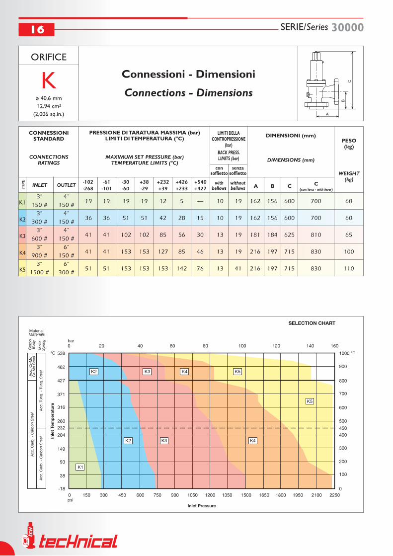
K1
K2
K3
K4
K5
SERIE/Series 3000016
ORIFICE
Kø 40.6 mm12.94 cm2
(2,006 sq.in.)
3” 4” 19 19 19 19 12 5 — 10 19 162 156 600 700 60
150 # 150 # 3” 4”
36 36 51 51 42 28 15 10 19 162 156 600 700 60 300 # 150 # 3” 4”
41 41 102 102 85 56 30 13 19 181 184 625 810 65 600 # 150 # 3” 6”
41 41 153 153 127 85 46 13 19 216 197 715 830 100 900 # 150 # 3” 6”
51 51 153 153 153 142 76 13 41 216 197 715 830 110 1500 # 300 #
CONNESSIONISTANDARD
CONNECTIONSRATINGS
PRESSIONE DI TARATURA MASSIMA (bar)LIMITI DI TEMPERATURA (°C)
MAXIMUM SET PRESSURE (bar)TEMPERATURE LIMITS (°C)
LIMITI DELLACONTROPRESSIONE
(bar)BACK PRESS.LIMITS (bar)
DIMENSIONI (mm)
DIMENSIONS (mm)
PESO(kg)
WEIGHT(kg)
INLET OUTLET-102-268
-61-101
-30-60
+38-29
+232+39
+426+233
+540+427
consoffietto
senzasoffietto
withbellows
withoutbellows
A
B
C
Connessioni - Dimensioni
Connections - Dimensions
A B C C(con leva - with lever)T
YPE

SERIE/Series 30000 17
L1
L2
L3
L4
L5
L6
ORIFICE
Lø 50.6 mm20.10 cm2
(3,116 sq.in.)
3” 4” 19 19 19 19 12 5 — 7 19 165 156 600 700 65
150 # 150 # 3” 4”
19 19 20 20 20 20 — 7 19 165 156 600 700 65 300 # 150 # 4” 6”
36 36 51 51 42 28 15 11 19 181 179 700 810 90 300 # 150 # 4” 6”
36 36 68 68 68 56 30 11 19 203 179 700 810 100 600 # 150 # 4” 6”
48 48 103 103 103 85 46 11 19 222 197 715 830 120 900 # 150 # 4” 6”
— — — — 103 103 76 11 19 222 197 715 830 120 1500 # 150 #
CONNESSIONISTANDARD
CONNECTIONSRATINGS
PRESSIONE DI TARATURA MASSIMA (bar)LIMITI DI TEMPERATURA (°C)
MAXIMUM SET PRESSURE (bar)TEMPERATURE LIMITS (°C)
LIMITI DELLACONTROPRESSIONE
(bar)BACK PRESS.LIMITS (bar)
DIMENSIONI (mm)
DIMENSIONS (mm)
PESO(kg)
WEIGHT(kg)
INLET OUTLET-102-268
-61-101
-30-60
+38-29
+232+39
+426+233
+540+427
consoffietto
senzasoffietto
withbellows
withoutbellows
A
B
C
Connessioni - Dimensioni
Connections - Dimensions
A B C C(con leva - with lever)T
YPE

M1
M2
M3
M4
SERIE/Series 3000018
ORIFICE
Mø 56.8 mm25.33 cm2
(3,927 sq.in.)
4” 6” 19 19 19 19 12 5 — 5 19 184 178 730 810 100
150 # 150 # 4” 6”
36 36 51 51 42 28 15 11 19 184 178 730 810 100 300 # 150 # 4” 6”
41 41 75 75 75 56 30 11 19 203 178 760 840 110 600 # 150 # 4” 6”
— — — — 75 75 46 11 19 222 197 760 840 130 900 # 150 #
CONNESSIONI
CONNECTIONS
PRESSIONE DI TARATURA MASSIMA (bar)LIMITI DI TEMPERATURA (°C)
MAXIMUM SET PRESSURE (bar)TEMPERATURE LIMITS (°C)
LIMITI DELLACONTROPRESSIONE
(bar)BACK PRESS.LIMITS (bar)
DIMENSIONI (mm)
DIMENSIONS (mm)
PESO(kg)
WEIGHT(kg)
INLET OUTLET-102-268
-61-101
-30-60
+38-29
+232+39
+426+233
+540+427
consoffietto
senzasoffietto
withbellows
withoutbellows
A
B
C
Connessioni - Dimensioni
Connections - Dimensions
A B C C(con leva - with lever)T
YPE

SERIE/Series 30000 19
N1
N2
N3
N4
ORIFICE
Nø 62.4 mm30.58 cm2
(4,740 sq.in.)
4” 6” 19 19 19 19 12 5 — 5 19 210 197 730 810 100
150 # 150 # 4” 6”
31 31 51 51 42 28 15 11 19 210 197 730 810 110 300 # 150 # 4” 6”
34 34 68 68 68 56 30 11 19 222 197 760 830 120 600 # 150 # 4” 6”
— — — — 68 68 46 11 19 222 197 760 830 140 900 # 150 #
CONNESSIONI
CONNECTIONS
PRESSIONE DI TARATURA MASSIMA (bar)LIMITI DI TEMPERATURA (°C)
MAXIMUM SET PRESSURE (bar)TEMPERATURE LIMITS (°C)
LIMITI DELLACONTROPRESSIONE
(bar)BACK PRESS.LIMITS (bar)
DIMENSIONI (mm)
DIMENSIONS (mm)
PESO(kg)
WEIGHT(kg)
INLET OUTLET-102-268
-61-101
-30-60
+38-29
+232+39
+426+233
+540+427
consoffietto
senzasoffietto
withbellows
withoutbellows
A
B
C
Connessioni - Dimensioni
Connections - Dimensions
A B C C(con leva - with lever)T
YPE

P1
P2
PC
P3
P4
SERIE/Series 3000020
ORIFICE
Pø 75.7 mm45.00 cm2
(6,976 sq.in.)
4” 6” 12 12 19 19 12 5 — 5 19 229 181 730 810 110
150 # 150 # 4” 6”
12 12 20 20 20 20 — 5 19 229 181 730 810 110 300 # 150 # 4” 6”
20 20 36 36 36 28 15 10 19 254 225 730 810 115 300 # 150 # 4” 6”
33 33 68 68 68 56 30 10 19 254 225 730 810 120 600 # 150 # 4” 6”
— — — — 68 68 46 10 19 254 225 760 900 140 900 # 150 #
CONNESSIONI
CONNECTIONS
PRESSIONE DI TARATURA MASSIMA (bar)LIMITI DI TEMPERATURA (°C)
MAXIMUM SET PRESSURE (bar)TEMPERATURE LIMITS (°C)
LIMITI DELLACONTROPRESSIONE
(bar)BACK PRESS.LIMITS (bar)
DIMENSIONI (mm)
DIMENSIONS (mm)
PESO(kg)
WEIGHT(kg)
INLET OUTLET-102-268
-61-101
-30-60
+38-29
+232+39
+426+233
+540+427
consoffietto
senzasoffietto
withbellows
withoutbellows
A
B
C
Connessioni - Dimensioni
Connections - Dimensions
A B C C(con leva - with lever)T
YPE

SERIE/Series 30000 21
Q1
Q2
Q3
ORIFICE
Qø 99.6 mm77.91 cm2
(12,07 sq.in.)
6” 8” 11 11 11 11 11 5 — 4 8 241 240 970 1140 235
150 # 150 # 6” 8”
17 17 20 20 20 20 11 8 8 241 240 970 1140 235 300 # 150 # 6” 8”
20 20 41 41 41 41 30 8 8 241 240 970 1140 250 600 # 150 #
CONNESSIONI
CONNECTIONS
PRESSIONE DI TARATURA MASSIMA (bar)LIMITI DI TEMPERATURA (°C)
MAXIMUM SET PRESSURE (bar)TEMPERATURE LIMITS (°C)
LIMITI DELLACONTROPRESSIONE
(bar)BACK PRESS.LIMITS (bar)
DIMENSIONI (mm)
DIMENSIONS (mm)
PESO(kg)
WEIGHT(kg)
INLET OUTLET-102-268
-61-101
-30-60
+38-29
+232+39
+426+233
+540+427
consoffietto
senzasoffietto
withbellows
withoutbellows
A
B
C
Connessioni - Dimensioni
Connections - Dimensions
A B C C(con leva - with lever)T
YPE

R1
R2
R3
R4
SERIE/Series 3000022
ORIFICE
Rø 119.8 mm112.7 cm2
(17,47 sq.in.)
6” 8” 3,5 3,5 7 7 7 5 — 4 4 241 240 990 1140 245
150 # 150 # 6” 8”
3,5 3,5 7 7 7 7 7 4 4 241 240 990 1140 245 300 # 150 # 6” 10”
10 10 15 15 15 15 — 7 7 267 240 990 1140 250 300 # 150 # 6” 10”
14 14 20 20 20 20 20 7 7 267 240 990 1140 260 600 # 150 #
CONNESSIONI
CONNECTIONS
PRESSIONE DI TARATURA MASSIMA (bar)LIMITI DI TEMPERATURA (°C)
MAXIMUM SET PRESSURE (bar)TEMPERATURE LIMITS (°C)
LIMITI DELLACONTROPRESSIONE
(bar)BACK PRESS.LIMITS (bar)
DIMENSIONI (mm)
DIMENSIONS (mm)
PESO(kg)
WEIGHT(kg)
INLET OUTLET-102-268
-61-101
-30-60
+38-29
+232+39
+426+233
+540+427
consoffietto
senzasoffietto
withbellows
withoutbellows
A
B
C
Connessioni - Dimensioni
Connections - Dimensions
A B C C(con leva - with lever)T
YPE

SERIE/Series 30000 23
T1
T2
ORIFICE
Tø 152.8 mm183.3 cm2
(28,42 sq.in.)
8” 10” 3,5 3,5 4,5 4,5 4,5 4,5 — 2 2 279 276 1100 1250 270
150 # 150 # 8” 10”
4,5 4,5 8 20 20 20 15 7 7 279 276 1100 1250 280
300 # 150 #
CONNESSIONI
CONNECTIONS
PRESSIONE DI TARATURA MASSIMA (bar)LIMITI DI TEMPERATURA (°C)
MAXIMUM SET PRESSURE (bar)TEMPERATURE LIMITS (°C)
LIMITI DELLACONTROPRESSIONE
(bar)BACK PRESS.LIMITS (bar)
DIMENSIONI (mm)
DIMENSIONS (mm)
PESO(kg)
WEIGHT(kg)
INLET OUTLET-102-268
-61-101
-30-60
+38-29
+232+39
+426+233
+540+427
consoffietto
senzasoffietto
withbellows
withoutbellows
A
B
C
Connessioni - Dimensioni
Connections - Dimensions
A B C C(con leva - with lever)T
YPE

SERIE/Series 3000024
Calcolo valvole di sicurezza • Safety relief valves calculation
Per un corretto dimensionamento delle valvole di sicurezza occorre conoscere preliminariamente i seguenti dati tecnici:
Dati Indispensabili • Necessary Data Dati Accessori • Addiotional Data
- taratura • set pressure
- peso molecolare • molecolar weight
- esponente di espansione isentropico X = Cp/Cv ratio of specific heats X = Cp/Cv
Ipotesi di calcolo • Calculation hypothesis
- contropressione • back pressure
- temperatura di scarico • discharge temperature
- fattore di comprimibilità • compressibility factor
- norme di calcolo • calculation rules
MASSIMA PORTATA GAS
Gas Max Flow Rate
- taratura • set pressure
- peso specifico • specific gravity
- contropressione • back pressure
- viscosità • viscosity
- sovrapressione ammessa • allowed overpressure
- norme di calcolo • calculation rulesMASSIMA PORTATA LIQUIDI
Liquid Max Flow Rate
- taratura • set pressure
- portata massima • max flow rate
- peso molecolare • molecular weight
- esponente di espansione isentropico X = Cp/Cv ratio of specific heats X = Cp/Cv- temperatura di scarico • discharge temperature
- contropressione • back pressure
- fattore di comprimibilità • compressibility factor
- norme di calcolo • calculation rules
CALCOLO ORIFIZIO GAS
Gas Orifice Calculation
- taratura • set pressure
- portata massima • max flow rate
- peso specifico • specific gravity
- contropressione • back pressure
- viscosità • viscosity
- sovrapressione ammessa • allowed overpressure
- norme di calcolo • calculation rules
INCENDIO RECIPIENTI CONTENENTI LIQUIDI
Fire Wetted Surface
CALCOLO ORIFIZIO LIQUIDI
Liquid Orifice Calculation
- taratura • set pressure
- superficie esterna serbatoio • external tank surface
- fattore di isolamento serbatoio • tank enviromental factor
- calore latente di vaporizzazione • latent heat of vaporization
- peso molecolare • molecular weight
- esponente di espansione isentropico X = Cp/Cv ratio of specific heats X = Cp/Cv- temperatura di vaporizzazione • vaporization temperature
- contropressione • back pressure
- fattore di comprimibilità • compressibility factor
- sovrapressione ammessa • allowed overpressure
- norme di calcolo • calculation rules
- taratura • set pressure
- superficie esterna serbatoio • external tank surface
- fattore di isolamento serbatoio • tank enviromental factor
- peso molecolare • molecular weight
- esponente di espansione isentropico X = Cp/Cv ratio of specific heats X = Cp/Cv- pressione di esercizio • exercise pressure
- temperatura di esercizio • exercise temperature
- contropressione • back pressure
- fattore di comprimibilità • compressibility factor
- sovrapressione ammessa • allowed overpressure
- norme di calcolo • calculation rules
INCENDIO RECIPIENTI CONTENENTI GAS
Fire Unwetted Surface
To dimension correctly safety relief valves it is necessary to know the following fluid data:

SERIE/Series 30000 25
Certificati • Certificates

PandID®B.V. - t: +31 174 280 371 - f: +31 174 280 853 - i: www.pandid.nl - e: [email protected]


![PowerPoint Presentation · 2019-02-01 · vera e of COEFF 0.4 0.35 0.3 0.25 0.2 0.15 0.1 0.05 3x5 Copier Linen stock 0.25 hz 3x5 stock Coeff. Friction - 3 factors [paper/pencil/speed]](https://img.pdfslide.us/doc/110x75/5ecb99c60082e632043c9bf5/powerpoint-presentation-2019-02-01-vera-e-of-coeff-04-035-03-025-02-015.jpg)


![D6HE4A 365 380 - NSP€¦ · 3 1000 800 SOO 400 200 Voltage [V] Temperature 250C 120 E 80 0 60 40 Temp. Temp. 20 Temp. -25 Coeff. Coeff. Coeff. of Isc - of Voc - of Pmax - 15](https://img.pdfslide.us/doc/110x75/5b6a8d007f8b9a51308c9961/d6he4a-365-380-nsp-3-1000-800-soo-400-200-voltage-v-temperature-250c-120.jpg)