Embed Size (px)
Citation preview
UNIVERSITY OF PUNE Syllabus
T. E. Instrumentation & Control (2012 Course)
DR. C. Y. PATIL
Chairman (Board of Studies)
Instrumentation & Control Engineering
T.E. Instrumentation Syllabus 2012 Course Page 1
University of Pune
Syllabus for T. E. Instrumentation and Control ‐ 2012 course
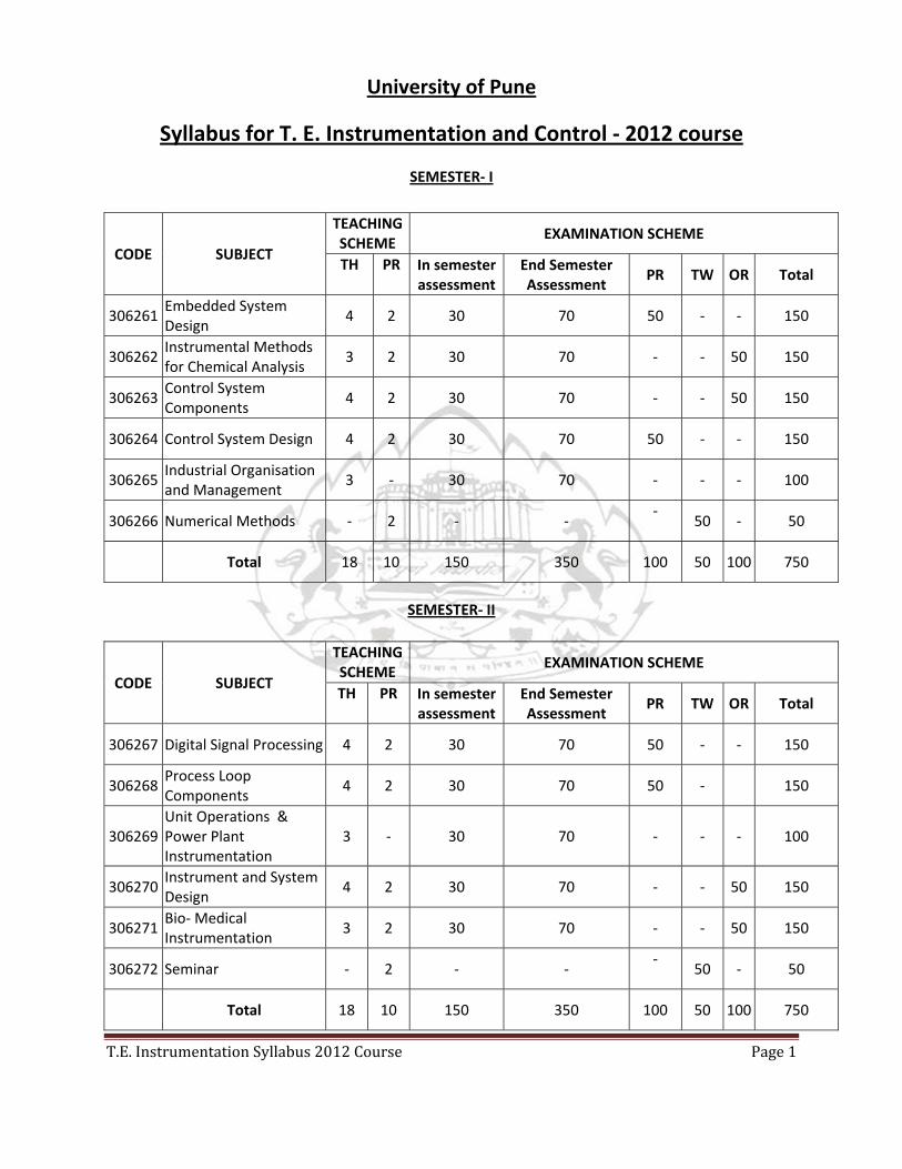
SEMESTER‐ I
SEMESTER‐ II
CODE SUBJECT
TEACHING SCHEME
EXAMINATION SCHEME
TH PR In semester assessment
End Semester Assessment
PR TW OR Total
306261 Embedded System Design
4 2 30 70 50 ‐ ‐ 150
306262 Instrumental Methods for Chemical Analysis
3 2 30 70 ‐ ‐ 50 150
306263 Control System Components
4 2 30 70 ‐ ‐ 50 150
306264 Control System Design 4 2 30 70 50 ‐ ‐ 150
306265 Industrial Organisation and Management
3 ‐ 30 70 ‐ ‐ ‐ 100
306266 Numerical Methods ‐ 2 ‐ ‐ ‐
50 ‐ 50
Total 18 10 150 350 100 50 100 750
CODE SUBJECT
TEACHING SCHEME
EXAMINATION SCHEME
TH PR In semester assessment
End Semester Assessment
PR TW OR Total
306267 Digital Signal Processing 4 2 30 70 50 ‐ ‐ 150
306268 Process Loop Components
4 2 30 70 50 ‐ 150
306269 Unit Operations & Power Plant Instrumentation
3 ‐ 30 70 ‐ ‐ ‐ 100
306270 Instrument and System Design
4 2 30 70 ‐ ‐ 50 150
306271 Bio‐ Medical Instrumentation
3 2 30 70 ‐ ‐ 50 150
306272 Seminar ‐ 2 ‐ ‐ ‐
50 ‐ 50
Total 18 10 150 350 100 50 100 750

SEMESTER- I

T.E. Instrumentation Syllabus 2012 Course Page 2
306261: Embedded System Design
Teaching Scheme:
Lectures: 4 Hrs/ Week
Practical: 2 Hrs/ Week
Examination Scheme:
Paper: (30+70) 100 Marks
In semester Assessment: 30 Marks
End Semester Assessment: 70 Marks.
Practical: 50 Marks
Prerequisites: Students should be familiar with Digital Electronics, Digital Logic Design.
Course Objectives:
1. To Understand the architectural detail of 8051 & AVR microcontroller
2. To Develop ability to program the 8051 & AVR microcontroller
3. To Develop ability to do the marriage of software & Hardware of 8051 & AVR
4. To develop ability to design and implement an application of embedded system
Unit I: Introduction to Microcontrollers & Embedded processors :
Architectural Overview & Features, The MCS‐51 Microcontroller family, Block diagram of 8051, Pin
Description, Connections of reset & oscillator pins, 8051 oscillator & clock , machine cycle,
Memory Organization , Addressing Modes, Instruction Set, Assembler Directives, Generating loops,
Delays, Software delay calculations, Programming examples, Programming in C.
Unit II:
Port , Timer/counter & interrupt s of 8051
I/O Ports and structure of all ports.
Timer/ counters, internal block diagram, Calculations for delays, Configuration of timers/ counters
for generating delays, frequency measurements, pulse width measurement, event counting.
Programming for Timers/Counters in Assembly and C
Interrupt structure, interrupt priority, vector addresses, interrupt configuration and handling,
programming for interrupts. Concept of stack memory, working of stack memory and its role in
subroutines and interrupt service routines.
Unit III:
Serial Communication & External world interfacing of 8051:
Serial Communication concept, Baud rate calculations, configuration of special function registers,
programming for serial communications based on interrupt and polling.
Interfacing of LED Displays and multiplexed LED displays, LCD displays, Keyboards
Interfacing of parallel DAC & ADC, Programming for interfacing
T.E. Instrumentation Syllabus 2012 Course Page 3
Unit IV:
Real world interfacing to 8051 & Project based learning:
Interfacing of Sensors, Interfacing of Stepper motor, Relays, RTC
Interfacing of Serial ADC and Serial EEPROM
Project based learning of embedded system: Temperature controller to maintain the temperature
at constant value with tolerance of +/‐ 20 C using interrupts, traffic light controller, Line tracer
robot.
Unit V:
The AVR Microcontroller :
Introduction to AVR family, Features of AT Mega8535 Microcontroller, Architecture, Register File,
Memory organization , Stack operation , port operation, Watch Dog timer, The AVR Instruction
set & programming in Assembly and C
Interrupts in AVR Atmega8535, Interrupt handling, Interrupt priority
Unit VI:
Timer/counter, UART & ADC of AVR of Atmega8535
8 bit timer/counter 0 with PWM‐ Block diagram, clock sources, pre‐scalar, counter unit, compare
unit, compare match output unit , modes of operation, 8 bit timer counter register and
programming of timer counter using assembly and C.
UART (Only Asynchronous receiver transmitter and not USART ) – Baud Rate generation, frame
formats, UART initialization, data transmission & Reception , UART register description
ADC of Atmega 8535 ‐ Features, operation , starting conversion, pre‐scaling, changing channel or
reference selection, ADC registers and its Configuration .
List of Experiments :
Students are expected to perform Minimum 8 Experiments ( 5 from 8051 + 3 from AVR )
1. Basic Programs: Arithmetic logical operations, Code Conversions.
2. Basic Programs: Counting/Looping, Stack operations
3. Program for configuration of Timers as timers and counter for:
a. Pulse width measurement
b. Frequency measurement
c. Square wave generation
4. Interfacing of Digital to Analog Converter or Analog to Digital Converter ICs.
5. Interfacing of LCD display.
6. Interfacing of Keyboard .
7. Program for transmitting data serially to PC.
T.E. Instrumentation Syllabus 2012 Course Page 4
AT Mega8535
8. Basic Programs: Arithmetic logical operations, Code Conversions.
9. A Square wave generation using timer counter in C language.
10. Configuration of ADC of Atmega 8535 using C language.
11. Interfacing of LCD display to AVR using C language.
Text Books:
1. The 8051 Microcontroller & Embedded Systems by M. A. Mazidi & J. G. Mazidi & Mckinlay,
Pearson Prentice Hall.
2. Microcontrollers: Theory & Applications by Dr. A. V. Deshmukh, Tata McGraw Hill,
Publications
3. Programming and Customizing the AVR Microcontroller by Dhananjay V. Gadre, Tata
McGraw Hill Publishing Company Limited, 2003.
4. AVR microcontroller & Embedded System by A. Mazidi , Prentice Hall .
Reference Books:
1. The 8051 Microcontroller Architecture, Programming and Applications by Kenneth J. Ayala ,
Penram International Publications.
2. The 8051 Microcontroller by Scott Mackenzie , Prentice – Hall of India Private Limited , New
Delhi
3. Internet resources for AVR:
a. Atmel AVR Page:. http://www.atmel.com/images/doc2502.pdf
b. http://www.atmel.in/Images/doc0856.pdf
T.E. Instrumentation Syllabus 2012 Course Page 5
306262: Instrumental Methods for Chemical Analysis
Teaching Scheme:
Lectures: 3 Hrs/ Week
Practical: 2 Hrs/ Week
Examination Scheme:
Paper: (30+70) 100 Marks
In semester Assessment: 30 Marks
End Semester Assessment: 70 Marks.
Oral : 50 Marks
Unit I: Introduction:
A. Introduction to Chemical Instrumental Analysis, advantages over classical methods, classification, various units used in chemical analysis.
B. Introduction to Electro analytical methods, potentiometry, voltametry, coulometry
Unit II: Spectrometric Methods‐I
A. Laws of Photometry, UV‐visible instrument component, photocolorimeters, single and double beam instruments, various types of UV‐visible spectrophotometers.
B. Atomic absorption spectrophotometer: Principle, working, hollow cathode lamp, atomizer, back‐ground correction.
Unit III: Spectrometric Methods‐ll.
A. IR spectroscopy: Principle, IR sources, IR detectors, dispersive and Fourier Transform IR spectroscopy.
B. Atomic Emission Spectroscopy: Principle, types, Flame photometer, DC arc and AC arc excitation, plasma excitation.
Unit IV: Spectrometric Methods‐III and Miscellaneous Instruments
A. Fluorimeters and Phosphorimeters: Principle, spectrofluorimeters, spectrophosporimeter, Raman effect, Raman spectrometer
B. Nuclear Magnetic Resonance (NMR) spectrometry. Chemical shift principle, working of NMR, FT‐NMR
C. Gas analysers: CO, C02, Hydrocarbons, 02, NOX
Unit V: Separative Methods
A. Mass Spectrometer(MS): Principle, ionisation methods, mass analyzer types ‐ magnetic deflection type time of flight, quadrupole, double focusing, detectors for MS.
T.E. Instrumentation Syllabus 2012 Course Page 6
B. Chromatography: Classification, Gas chromatography: principle, constructional details, GC detectors, High Predominance Liquid Chromatography (HPLC): principle, constructional details, HPLC detectors
Unit VI: Radioactive Instrumentation
A. X‐ray spectrometry: Instrumentation for X‐ray spectrometry, X‐ray diffractometer: Bragg's law, Auger emission spectroscopy, Electron spectroscopy for chemical analysis(ESCA) .
B. Radiation detectors: Ionisation chamber, Geiger‐Muller counter, proportional counter, scintillation counters.
List of Experiments :
Students are expected to perform Minimum 8 Experiments : 1. Study of filter photometer. 2. Study of flame photometer. 3. Study of optical densitometer. 4. Study of UV‐visible spectrophotometer. 5. Study of Mass spectrometer. 6. Study of Gas Chromatograph. 7. Study of HPLC. 8. Study of Atomic Absorption Spectrophotometer. 9. Study of NMR. 10. Study of ESR.
Text Books: 1. Instrumental Methods of Analysis, Willard, Merritt, Dean, Settle, CBS Publishers & Distributors,
New Delhi, Seventh edition. 2. Instrumental Methods of Chemical Analysis, Galen W. Ewing, McGraw‐Hill Book Company,
Fifth edition
Reference Books: 1. Introduction to Instrumental Analysis, Robert D. Braun, McGraw‐Hill Book Company. 2. Principles of Instrumental Analysis, Skoog, Holler, Nieman, Saunders College Publishing, 1998.

T.E. Instrumentation Syllabus 2012 Course Page 7
306263: Control System Components
Teaching Scheme:
Lectures: 4 Hrs/ Week
Practical: 2 Hrs/ Week
Examination Scheme:
Paper: (30+70) 100 Marks
In semester Assessment: 30 Marks
End Semester Assessment: 70 Marks.
Oral: 50 Marks
Prerequisites: DC/AC Motors, Flapper Nozzle Transducer
Unit I: Industrial Control Devices: 1. Switches: Construction, symbolic representation, working, application of Toggle switch, Slide switch, DIP
switch, Rotary switch, Thumbwheel switch, Selector switch, Push button, Drum switch, Limit switch, Temperature switch, Pressure switch, Level switch, Flow switch.
2. Relays: Construction, working, specifications/selection criteria and applications of electromechanical
relay,
Reed relay, hermetically sealed relay, Solid state relays.
3. Contactors Construction, working, specifications and applications of contactors. Comparison between relay
& contactor.
Unit II: Sequencing & Interlocking for Motors: Standard symbols used for Electrical Wiring Diagram, Electrical Wiring Diagram in relation to motors:
Concept of sequencing & Interlocking .
Starting, Stopping, Emergency shutdown, (Direct on line, star delta)
Protection of motors: Short circuit protection, Over load Protection, Low/Under
Voltage Protection, Phase reversal Protection, Over temperature Protection.
Reversing direction of rotation.
Braking.
Starting with variable speeds.
Jogging/Inching
Motor Control Center: Concept and wiring diagrams
T.E. Instrumentation Syllabus 2012 Course Page 8
Unit III: Introduction to Pneumatic, Hydraulic & Electrical systems & their Comparison Pneumatics
Pneumatic components
Pneumatic Power Supply and its components
Pneumatic relay (Bleed & Non bleed, Reverse & direct)
Single acting & Double acting cylinder
Special cylinders: Cushion, Double rod, Tandem, Multiple position, Rotary
Filter Regulator Lubricator (FRL)
Pneumatic valves (direction controlled valves, flow control etc)
Special types of valves like relief valve, pressure reducing etc.
Time delay valve
Air motors
Pneumatic Circuits
Standard Symbols used for developing pneumatic circuits
Sequence diagram (step‐displacement) for implementing pneumatic circuits
Different Pneumatic Circuits: Reciprocating, Sequencing, Anti‐cycle repetition, Block transfer, Speed regulation etc
Unit IV: Hydraulics
Hydraulic components:
Hydraulic supply
Hydraulic pumps
Actuator (cylinder & motor)
Hydraulic valves
Hydraulic Circuits
Standard Symbols for developing hydraulic circuits
Different Hydraulic Circuits: Meter in, Meter out, Reciprocating, speed control, Sequencing of cylinders, Direction control etc
T.E. Instrumentation Syllabus 2012 Course Page 9
Unit V: Auxiliary components
Construction, working & applications of: Synchros, Feeders, Dampers, Alarm annunciator,
High/low selectors, Flow totalizer, Computing relays, Seals, Snubber.
Circuit Breaker: Need of Circuit Breaker, Operating Principle, and Types. Fuses: Desirable
characteristics, Materials according to rating, Terminology (Fusing Current, Current rating of
fuse element, fusing factor) & Types of fuses.
Unit VI: Fluidic Control Devices:
Characteristics, Principle of Operation, Bistable & Proportional Amplifier & applications.
Safety in Instrumentation & Control Systems:
Hazardous Area & Material classification as per NEC Standards, Explosion Proof Housing,
Encapsulation, Sealing, & Immersion, Purging systems.
Intrinsic Safety: ‐Definition, Designing for intrinsic Safety, Isolation or Encapsulation (Series &
Shunt Protective elements, & Zener barrier)
List of Experiments : Students are expected to perform Minimum 8 Experiments :
1. Implementation of Logic Gates using relays. 2. Study of various pneumatic and hydraulic components and power supplies. 3. Implementation and testing of Pneumatic circuits. 4. Implementation and testing of Hydraulic circuits. 5. Study of Synchro transmitter and receiver system 6. Study of Pressure/temperature/level/flow Switches (any two). 7. Study of Motor control Center based on industrial visit. 8. Study and Calibration of P/I converter. 9. Demonstration & study of auxiliary components like, flow totalizer, Alarm annunciator,
computing relay (any two) 10. Designing intrinsic safety circuits (Zener barriers)
Text Books:
1. Industrial Electronics, Petruzella, McGraw‐Hill 2. Pneumatic Instrumentation, Majumdhar, TMH 3. Industrial Hydraulics, Pipenger 4. Process Control, Instrument Engineering Hand book, B.G. Liptak, Butterworth‐Heinemann Ltd
Reference Books:
1. Pneumatics, Festo Didactic 2. Hydraulics, Festo Didactic 3. Process control and Instrument technology, C.D.Johnson, TMH.
T.E. Instrumentation Syllabus 2012 Course Page 10
306264: Control System Design
Teaching Scheme:
Lectures: 4 Hrs/ Week
Practical: 2 Hrs/ Week
Examination Scheme:
Paper: (30+70) 100 Marks
In semester Assessment: 30 Marks
End Semester Assessment: 70 Marks.
Practical: 50 Marks
Unit I: Compensators and compensator design: Need of compensators, types of compensators (series, feedback and feed‐forward – introduction only). Types of series compensators (lead, lag, lag‐lead) and their transfer functions, Electrical lead, lag and lag‐ lead compensating networks. Root locus approach: Effect of addition of zero, addition of pole. Design of lead, lag and lag‐lead compensator using root locus approach. Frequency response of lag, lead and lag‐lead compensator. Compensator design using Bode plot approach: Lead, lag and lag‐lead compensator design using Bode plot approach. Unit II: Control actions and Controller tuning: Control actions (ON‐OFF, proportional, integral, derivative, proportional plus integral, proportional plus derivative, proportional plus integral plus derivative, Controller tuning by Ziegler‐Nichols methods (step response reaction curve method and frequency response method), Cohen Coon tuning method, Obtaining controller settings (kp,Ti,Td) through Ziegler‐Nichols frequency response method using Routh array and Bode plot approaches.
Unit III: Controller Design: Design of PI/PD/PID controller for getting required performance specifications (damping factor, natural frequency, steady state error, phase margin, static error constants) using root locus and Bode plot approaches, Direct synthesis of controller, controller design for systems with and without dead time through controller synthesis formula.
Unit IV: Introduction to state space representation: Advantages of state space representation over classical representation. Terminology of state space (state, state variables, state equations, state space). Obtaining state model from transfer function by direct (companion I and II i.e. controllable canonical and observable canonical forms), parallel and cascade decomposition, Conversion of state model to transfer function. Unit V: Analysis of control system in state space: Solution of state equation, diagonalisation of plant matrix through similarity transformations, Vandermonde’s matrix, State transition matrix: Definition, derivation and properties, computation by Laplace transform method, Cayley Hamilton method, Similarity transformation method, concept of controllability: definition, derivation for the necessary and sufficiency condition for complete state
T.E. Instrumentation Syllabus 2012 Course Page 11
controllability, controllability matrix, concept of observability: definition, derivation for the necessary and sufficiency condition for complete state observability, observability matrix, Unit VI: Design concepts in state space: State variable feedback, control system design via pole placement: necessary and sufficiency condition, derivation for state feedback gain matrix K through sufficiency condition, Ackermann formula, coefficient comparison method. State observer: necessity, types, theory, design of full order state observer, principle of duality between state feedback gain matrix K and observer gain matrix Ke.
List of Experiments : Students are expected to perform Minimum 8 Experiments :
1. Study of magnitude and phase characteristics of lead, lag and lag‐lead compensator. 2. Design a lead / lag compensator for getting desired specifications by root locus approach. 3. Design a lead / lag compensator for getting desired specifications by Bode plot approach. 4. Simulation of controller settings of P,PI,PID controllers (kp,Ti,Td) obtained through Ziegler‐
Nichols first and second method, Cohen‐Coon method. 5. Design of PI/PD/PID controller for getting required performance specifications (damping
factor, natural frequency, steady state error, phase margin, static error constants) using root locus and Bode plot approaches.
6. Design a controller using direct controller synthesis for getting specified closed loop response.
7. Conversion of transfer function model to state space and vice‐versa. 8. Check for complete state controllability and complete state observability of a given system.9. Design a state feedback controller through pole placement. 10. Design full order state observer using principle of duality between state feedback gain
matrix K and observer gain matrix Ke. 11. Performance comparison two controller tuning methods (experiment number 4) based on
performance indices such as ISE, IAE, ITAE and ITSE.
Text Books: 1. B. S. Manke, “Control System Design”, 1st ed., Khanna Publishers, New Delhi, 2007. 2. I. J. Nagrath, M. Gopal, “Control System Engineering”, 3rd ed., New Age International Publishers,
1999. 3. K. Ogata, “Modern Control Engineering”, 2nd ed., PHI, New Delhi, 1994.
Reference Books:
1. Norman S. Nise, “Control System Engineering”, 4th ed., John Wiley and Sons, 2003. 2. B. C. Kuo, “Automatic Control Systems”, 3rd ed., PHI New Delhi, 1979. 3. Graham C. Goodwin, Stefan F. Graebe and M. E. Salgado, “Control system Design”, PHI, New
Delhi, 2002.
T.E. Instrumentation Syllabus 2012 Course Page 12
306265: Industrial Organisation and Management
Teaching Scheme:
Lectures: 3 Hrs/ Week
Examination Scheme:
Paper: (30+70) 100 Marks
In semester Assessment: 30 Marks
End Semester Assessment: 70 Marks.
Unit I: Industrial Management and Business organization:
Definition of business, characteristics and classifications, objectives, types of business organizations‐
characteristics, levels of management, characteristics and objectives. Hierarchical structure and
organization of group, Functions of management‐ forecasting, organizing, directing, motivating,
planning, co‐ordinating, controlling, communication, leadership etc.
Developing Business environment: SWOT analysis, BCG Matrix, Porter’s 5 forces of competition.
Management techniques for developing strategy viz., Balanced score card, Performance Management
and analysis techniques viz. Ishikawa diagrams, Business process Re‐engineering
Unit II: Quality, Inspection and Environment Management :
Quality Circles/ Forums, Quality Objectives, use of Statistical Process Control, Introduction to ISO 9000
Inspection: objectives, Principles, standards, Qualities of inspector, Role of R & D, Innovation, Business
expansion, Diversion, Mergers and Takeovers
Environmental pollution:‐ ecology, factors causing pollution, effect of pollution on human health, Air
pollution control, sources of pollution water pollution and control, solid waste management
Environmental norms: ISO 14000
Unit III: Production Planning, Inventory Control and Supply Chain Management:
Manufacturing Excellence, Outsourcing, Production planning techniques, Purchase and Inventory
Management, inventory control using Economic Order Quantity, Minimum Order Quantity, Ordering
Level, store keeping, Finished goods, semi finished goods, raw material handling and storage, Value
Addition, Supply Chain concepts and management for leveraging profit
Unit IV: Human Resources Management:
Manpower planning, Human Resources: exploiting true potential, Staff training and development,
Motivation, Selection and training of manpower, Appraisal and increments management, Leadership
skills, Delegation and development for growth. Objectives and Job Descriptions/ Role Summary
T.E. Instrumentation Syllabus 2012 Course Page 13
Unit V: Financial Management:
Capital Structure, Fixed & Working Capital, Sources of finance, Assets management,
Introduction to capital budgeting, Methods of capital budgeting: Budget definition and concept,
objective of budget, type of budget, preparation of budget, Balance Sheet, function of money market
and capital Market
Unit VI: Professional and Business ethics, IT and e‐business:
Concept of Ethics, ethics and morals, business ethics, Professional ethics. Need for professional and
business ethics.
Introduction to Management Information System (MIS), Enterprise Resource Planning Systems (ERP),
e‐business and strategies
Text Books: 1. Industrial organization and Engineering Economic‐ T. R. Banga and S. C. Sharma, Khanna
Publication. 2. Industrial Engineering and Management‐ O.P. Khanna, Dhanpat Rai Publication.
Reference Books: 1. Business Poly – Azar Kazmi 2. Resisting Intellectual property – Halbert, Taylor & Francis – 2007 – PHI 3. Management in Engineering‐ Gail Freeman‐ Bell and James Balkwill (PHI). 4. The New Era of Management – R. L. Daft, THOMSON (India Edition) 5. Modern Economic Theory‐ Dewett K. K. 6. Elementary Economic Theory‐ Dr. R. D. Gupta. 7. Business organization and Management‐ M.C. Shukla.
T.E. Instrumentation Syllabus 2012 Course Page 14
306266: Numerical Methods
Teaching Scheme:
Practical: 2 Hrs/ Week
Examination Scheme:
Term Work: 50 Marks
Objectives:
1. To understand fundamental methods required for scientific data analysis.
2. To apply a range of mathematical and technical concepts and methods to Control Engineering
List of Experiment:
Write and execute a program using C//MatLab/SciLab with algorithm and flowchart
1. To find the roots of non‐linear equation using Bisection method & Newton’s method. 2. To fit the curve by least – square approximation. 3. To solve the system of linear equations using Gauss‐Elimination method. 4. To integrate numerically using Trapezoidal rule. 5. To Integrate numerically using Simpson’s rules. 6. To find numerical solution of ordinary differential equations by Euler’s method. 7. To find numerical solution of ordinary differential equations by Runge‐Kutta method. 8. To find the largest Eigen value of a matrix by power‐method.
Note: All Practical’s are compulsory
Reference Book:
1. E. Balguruswami, “Numerical Methods”, Tata McGraw Hill Publication.
2. M. K. Jain, S. R. K. Tyengar, R. K. Jain, “Numerical Methods for Scientific and Engineering
Computation”,
New Age International Publishers

SEMESTER- II
T.E. Instrumentation Syllabus 2012 Course Page 15
306267: Digital Signal Processing
Teaching Scheme:
Lectures: 4 Hrs/ Week
Practical: 2 Hrs/ Week
Examination Scheme:
Paper: (30+70) 100 Marks
In semester Assessment: 30 Marks
End Semester Assessment: 70 Marks.
Practical: 50 Marks
AIM: To study the digital signal processing algorithms.
Objective:
To compute the discrete‐time convolution of two sequences.
To use concepts of linearity, stability, causality, time‐invariance to classify a discrete‐time
system.
To use the definition and properties of Z‐transforms to describe and analyze the behavior of
LTI systems.
To evaluate the frequency response of a discrete‐time, LTI systems from its impulse response
and vice‐versa.
To study DTFT, DFT, FFT and their computations.
Use DTFT, DFT, FFT to analyze discrete time signals and systems.
To study the design techniques for digital filters such that student will be able to design and
implement different frequency selective FIR and IIR filters to meet frequency domain
specifications.
Unit I: Introduction to Signals and Systems:
Definition of signal in continuous time (CT) and discrete time (DT), representation of signals in DT,
Classification of signals (CT/DT), Basic Signals (CT/DT), basic operations on signals (CT/DT) ‐time‐
scaling, time‐shifting, time‐reversing, amplitude scaling, additions, subtractions, multiplications,
derivative/difference, integral/sum.
Definitions of systems, classification of systems based on properties‐Linearity, Causality, Stability,
Memory, Invariance, and invertibility.
Convolution sum‐impulse response, properties of convolution. Correlation‐Auto‐correlation, Cross‐
correlation.
Unit II: (A) Sampling theorem, Z‐transforms by summation of left, right, and two‐sided sequences, Region of
Convergence and Z‐transform properties, pole‐zero plot, Inverse Z‐transform by partial‐fraction,
power‐series, and contour integration expansion, Solution of linear constant coefficient difference
equation (LCCDE) using Z‐transform.
(B)‐Frequency response characteristics: frequency response of Linear Time‐invariant (LTI) systems,
T.E. Instrumentation Syllabus 2012 Course Page 16
magnitude and phase response of LTI systems, ideal frequency selective filters, phase delay, group
delay.
Unit III: Fourier analysis in DT domain
Definition of discrete‐time Fourier series (DTFS), Computation of DTFS, Properties of DTFS,
Computation of Inverse DTFS.
Definition of discrete‐time Fourier transform (DTFT), Computation of DTFT, Properties of DTFT,
Computation of IDTFT.
Definition of Discrete Fourier transform (DFT), Computation of DFT, Properties of DFT, Circular
convolution, Computation of IDFT.
Unit IV: Fast Fourier Transform
Radix‐2 Decimation in time (DIT) FFT algorithm, Radix‐2 Decimation in frequency (DIF) algorithm, In‐
place computations, bit‐reversal, IFFT using DIT and DIF algorithms.
Unit V: Finite Impulse Response (FIR) Digital Filters
Symmetric and Antisymmetric FIR filters, Liner phase filters, Design of FIR filters using Hamming,
Rectangular, Hanning, Blackmann, and windows, Design of FIR filters using frequency sampling
method, Realization of FIR filters using transversal, linear phase and polyphase structures.
Unit VI: Infinite Impulse Response (IIR) Digital Filters
Review of design of analogue Butterworth and Chebyshev Filters, Design of IIR filters using impulse
invariance technique, Design of IIR filters using Bilinear transformation, Realization of IIR filters using
Direct form‐I, Direct form‐II, Cascade and Parallel Forms.
List of Experiments : Students are expected to perform Minimum 8 Experiments :
1. Write a Program to generate the basic signals.
2. Write a Program to implement the basic operations on the given signals.
3. Write a Program to implement Linear Convolution of the two given sequences.
4. Write a Program to obtain the auto‐correlation and Cross‐correlations of the given sequences.
5. Write a Program to obtain the transfer function and plot is pole‐zero plot
6. Write a Program to find the DTFT of the given sequence and plot its magnitude and phase plot.
7. Write a Program to find the DFT of the given sequences. Plot its magnitude and phase plot.
Also find its IDFT to obtain the original sequence.
8. Write a Program to obtain the circular convolution of the two given sequences.
T.E. Instrumentation Syllabus 2012 Course Page 17
9. Write a Program to obtain the linear convolution using circular convolution of two given
sequences.
10. Write a Program to obtain the DFT of the given sequences using DIT‐FFT algorithm and plot its
magnitude and phase spectrum.
11. Write a Program to obtain the DFT of the given sequences using DIF‐FFT algorithm and plot its
magnitude and phase spectrum.
12. Write a Program to design and implement FIR filters using difference windowing methods.
13. Write a Program to design and implement IIR filters (Using Butterworth or Chebyshev
approximations).
Text Books:
1. A. V. Oppenheim and R. W. Schafer, “Discrete Time Signal Processing”, Pearson Education.
2. J. G. Proakis and D. J. Manolakis, “Digital Signal Processing: Principles, Algorithms and
Applications”, PHI, 2000.
Reference Books:
1. B. Porat, “A Course in Digital Signal Processing”, J. Wiley and Sons.
2. J. R. Johnson, “Introduction to Digital Signal Processing”, PHI.
3. Rabiner, Gold, “Theory and Applications of Digital Signal Processing”, TMH.
4. S. K. Mitra, “Digital Signal Processing‐A Computer Based Approach”, MGH
5. E. C. Ifeachor and B. W. Jervis, “Digital Signal Processing‐A practical Approach”, Addison‐
Wesley publication
T.E. Instrumentation Syllabus 2012 Course Page 18
306268: Process Loop Components
Teaching Scheme:
Lectures: 4 Hrs/ Week
Practical: 2 Hrs/ Week
Examination Scheme:
Paper: (30+70) 100 Marks
In semester Assessment: 30 Marks
End Semester Assessment: 70 Marks.
Practical: 50 Marks
Prerequisites: Basics of Feedback Control System
Unit I: a. Fundamentals of process control:
Elements of process control loop, Concept of Process variables, set point, controlled variable, manipulated variable, load variable. Representation of Process loop components using standard symbols (basics with reference to control loop), and Examples of process loops like temperature, flow, level, pressure etc.
b. Transmitters:
Need of transmitter (concept of field area & control room area), Need for standardization of signals, Current, voltage, and pneumatic signal standards, Concept of live & dead zero.
Types of transmitters: Two and four wire transmitters, Electronic and Pneumatic transmitters
Electronic Capacitive Differential Pressure Transmitter: Types, Mounting (Installation),
Manifold, Calibration setup, Application of DPT for Level measurement, Zero elevation,
suppression, Square root extractor.
SMART: Comparison with conventional transmitter, Block schematic, Introduction to Wireless
transmitters.
Unit II: Controller Basics
Process Characteristics
Process load, Process lag, Self Regulation, Distance/velocity lag (dead time), Capacity. Control System Parameters
Error, Variable Range, Control Lag, Cycling, Direct/Reverse Action.
Control Actions Discontinuous: ON/OFF, Multiposition Control, Floating Control.
Continuous: Proportional (offset), Integral (Reset windup), Derivative, Proportional‐ Integral, Proportional‐ Derivative, Proportional‐ Integral‐derivative, Antireset windup, Rate before Reset, Concept of Bump less transfers in PID controller, Effect of process characteristics on PID combination, Selection & application of controller actions.
Unit III: Tuning of controller: Different Criteria like Quarter Amplitude Decay Ratio, Loop disturbance,
Optimum Control, Measure of Quality, Stability Criteria.
T.E. Instrumentation Syllabus 2012 Course Page 19
Tuning Methods: Process Reaction Curve (open loop), Ziegler Nichols (closed loop), &
Frequency Response Method.
Digital PID controllers: Velocity & Position algorithm, Block Schematic, Faceplate of Digital
controller, Introduction to Direct Digital Control.
Current to pneumatic converter & Pressure to Current converter Unit IV: Programmable Logic Controller (PLC)
Continuous versus Discrete Process Control, Relay based ladder diagram using standard
symbols, Limitations of relay based system. Architecture of PLC, Types of Input & Output
modules (AI, DI, DO, AO), Wiring diagram, Interfacing pneumatic & Hydraulic systems to PLC,
Fixed & Modular PLC (Rack, slot, grouping), PLC specifications, PLC manufacturers, PLC Basic
instructions, Timers (ON delay, OFF delay & Retentive) & Counters with timing diagrams, PLC
ladder diagram, PLC programming for process applications, Introduction to analog
programming.
Unit V: Control valve
Necessity, comparison with other final control elements, Control valve Characteristics: (Inherent & Installed) Control valve terminology: Rangeability, Turndown, valve capacity, viscosity index, AO, AC (Fail Safe Action) etc. Classification of control valve based on: valve body. Construction, type of actuation, application etc. Construction, Advantages, Disadvantages & applications of Globe: Single, double, 3way, angle, Gate, Needle, Diaphragm, Rotary valves, Ball, Butterfly. Types of actuators: Construction, Advantages, Disadvantages & applications: Spring Diaphragm & Smart actuators. Control valve accessories: Positioners: Applications/Need, Types, Effect on performance of Control valves. Solenoid valves, Hand wheel.
Unit VI: Control Valve Sizing
Cv sizing concept & basic equations
Designing control valve for gas, vapor and liquid services: Valve sizing by ANSI/ISA 75.01 STD,
Valve capacity testing by ANSI/ISA 75.02
Effect and remedies of cavitations and flashing.
Control valve noise generation and remedies
High temperature and High‐pressure service valves
Control valve dynamic performance.
Control valve application & selection
T.E. Instrumentation Syllabus 2012 Course Page 20
List of Experiments : Students are expected to perform Minimum 8 Experiments :
1. Study of D.P. Transmitter and its application for flow or level. 2. Study of Square Root Extractor. 3. Study and Calibration of I/P converter 4. Study & verification of different control actions (P, I, D, PI, PD, PID) for step Input. 5. Tuning of PID controller 6. Study of Control valve & plot the characteristics of Control valve 7. Control valve design using any software package. 8. Study of PLC and PLC Programming. 9. Study & Implementation of cascading of Timers and Counters 10. Interfacing PLC to hydraulic & pneumatic circuits
Text Books:
1. Process control and Instrument technology, C.D.Johnson, TMH 2. Instrumentation for Process measurement and control, N.A. Anderson, CRC Press 3. Introduction to Programmable Logic Controller, Gary Dunning, DELMAR Cengage Learning. 4. Programmable Logic Controller, Webb, PHI 5. Process Control, Instrument Engineering Hand book, B.G. Liptak, Butterworth‐Heinemann Ltd
Reference Books:
1. Tuning of Industrial control systems, ISA 2. Control valve Handbook, ISA 3. Process Instruments and Controls Handbook, Douglas M. Considine, McGraw‐Hill. 4. Programmable Logic Controller, NIIT 5. Fundamentals of Process Control Theory, Paul Murrill, ISA 6. Lessons In Industrial Instrumentation, By Tony R. Kuphaldt, Version 0.4 – Released January 11,
2009.
T.E. Instrumentation Syllabus 2012 Course Page 21
306269: Unit Operations and Power Plant Instrumentation
Teaching Scheme:
Lectures: 3 Hrs/ Week
Examination Scheme:
Paper: (30+70) 100 Marks
In semester Assessment: 30 Marks
End Semester Assessment: 70 Marks.
AIM: The course is designed to familiarize the student with the functions and instrumentation available in a modern power generation plant. COURSE OBJECTIVES:
1 To provide knowledge of Basics knowledge & Understanding of various Unit Operations used in Industry.
2 To provide an overview of different methods of power generation with a particular stress on thermal power generation.
3 To bring out the various measurements involved in power generation plants. 4 To provide knowledge about the different types of devices used for analysis. 5 To impart knowledge about the different types of controls and control loops. 6 To familiarize the student with the methods of monitoring different parameters like speed,
vibration of turbines and their control.
Unit I: Basics of Chemical engineering unit operations like; Fluid flow processes, including fluids transportation, filtration, and solids fluidization., Heat transfer processes, including evaporation, condensation, and heat exchange, Mass transfer processes, including gas absorption, distillation, extraction, adsorption, and drying, Thermodynamic processes, including gas liquefaction, and refrigeration, Mechanical processes, including solids transportation, crushing and pulverization, and screening and sieving. Basic concepts behind pumps, compressors, fans, blowers etc. Unit II: A. Heat Transfer: Importance of heat transfer in Chemical Engineering operations, Principles of heat flow in fluids, Heat transfer to fluids without phase change, Heat Transfer to fluids with phase change, Heat Exchange equipment, Evaporation Principle & types of evaporation, Crystallization: Definition, Nucleation and Crystal Growth.
B. Mass Transfer: Distillation: Vapor‐ Liquid Equilibrium, Ideal Solutions, Relative volatility, Azeotropic mixtures, Methods Of distillation: Flash, Continuous, Multi‐component system, Material balance and Analysis of Fractionating column by McCabe Thiele method.
Drying: Theory and Mechanism of Drying, Steady and Unsteady Drying, moisture content, total time of drying, Characteristics, Classification and selection of Industrial dryers.
T.E. Instrumentation Syllabus 2012 Course Page 22
Unit III: A. Energy sources, their availability, worldwide energy production, energy scenario of India. Introduction to Power generation: Classification: Renewable and non‐renewable energy generation resources. Renewable: Small Hydro, modern biomass, wind power, solar, geothermal and bio‐fuels. Nonrenewable: fossil fuels (coal, oil and natural gas) and nuclear power. Hydroelectric Power Plant: Site selection, Hydrology, classification of Hydropower plants, Types of Turbines for hydroelectric power plant, pumped storage plants, storage reservoir plants. Wind Energy: Power in wind, Conversion of wind power, types of wind turbine, and modes of operation, wind mill, wind pumps, wind farms, safety. Solar Energy: Solar resource, solar energy conversion systems: Solar PV technology: Block diagram of PV system, advantages and limitations. Solar thermal energy system: Principle, solar collector and its types, solar concentrator and its types, safety. Nuclear Power Plant: Nuclear power generation, control station and reactor control. Unit IV: A. Thermal Power Plant‐ Method of power generation, layout and energy conversion process, material handling systems. B. Boiler: Types of boilers like FBC, CFBC, DIPC, Fluidized Bed, boiler safety standards, Combustion control, air to fuel ratio control, three element drum level control, steam temperature and pressure control, burner management systems, boiler interlocks. Instrumentation for Boiler ancillaries viz. water treatment, electro‐static precipitator, soot blower, economizer, de aerator, super heater, chemical dosing systems, air pre‐heater, coal and ash handling systems, fuel storage and distribution, Bag House Filters. Unit V: Excess Air –Combustion Chemistry and products of Combustion‐ Requirements of Excess Combustion air –Calculation of efficiency of boilers –Input /output method – Heat loss method. Types of Turbines, Turbine instrumentation and control, start‐up and shut‐down, thermal stress control, condition monitoring & power distribution instrumentation. Synchronous, Induction generators Speed, Vibration, shell temperature monitoring and control‐steam pressure control – lubricant oiltemperature control – cooling system Unit VI: Comparison of thermal power plant, hydroelectric power plant, wind, solar, nuclear power plant on the basis of: Performance, efficiency, site selection, Economics‐capital and running, safety standards, pollution, effluent management and handling. Power plant safety, Pollution monitoring, control Sound, Air, smoke, dust, study of Electrostatic precipitator
T.E. Instrumentation Syllabus 2012 Course Page 23
Text Books: 1. McCabe, W.L., Smith, J.C., and Harriot, P., “Unit Operations in Chemical Engineering”, McGraw‐
Hill VII Edn., 2004. 2. Boiler Control Systems, David Lindsley, Mc‐Graw Hill 3. Power Plant Engineering, P.K.Nag, 3rd edition, 2010. McGraw Hill. 4. Power Plant Instrumentation, K. Krishnaswamy, M. PonniBala, PHI Learning Pvt. Ltd., 2011
Reference Books:
1. Process Control, B.G. Liptak 2. Power Plant Engineering, Domkundwar 3. Non‐conventional energy resources.by B. H. Khan, McGraw Hill, New Delhi. 4. Renewable energy Technology.Chetan Singh Solanki, Prentice Hall Publication. 5. Solar Energy, by S. P. Sukhatme, Tata McGraw Hill, New Delhi. 6. Nonconventional Energy Sources. G. D. Rai, Khanna Publication. 7. Energy Management Handbook: W.C. Taeruer 8. Pollution: M.N.Rao and H.V. Rao.
T.E. Instrumentation Syllabus 2012 Course Page 24
306270: Instrument and System Design
Teaching Scheme:
Lectures: 4 Hrs/ Week
Practical: 2 Hrs/ Week
Examination Scheme:
Paper: (30+70) 100 Marks
In semester Assessment: 30 Marks
End Semester Assessment: 70 Marks.
Oral: 50 Marks
Unit I: Basic concepts of instrument design:
Functional requirements and instrument specifications, Basics of standards used, NEMA and IP standards with special reference to packaging standards, Operational environment, Prototyping and testing. Unit II: Guidelines for enclosure, components and accessories:
Grounding and shielding techniques, noise in electronic circuits, EMI and EMC, Source of EMI, Protection against EMI, EMI and EMC effects minimization methods, ESD, Protection against ESD, Control panel layout, Ergonomics and Asthetics. Unit III: Analog system design guidelines and application: Single chip devices instrumentation amplifiers AD620, Linear opto isolator HCNR201, V to I converters XTR110, Signal conditioners AD594/595, Phase angle control TCA785. Unit IV: Digital system design guideline and application:
Single chip devices, Phase Locked Loop CD4046, Programmable counters ICM 7217, Digital Panel meters ICL7107, Optoisolator MCT2E, Power drivers ULN2803, CMOS Key Encoder MM74C922, DTMF Decoder MT8870 . Unit V: Printed circuit board design guidelines:
General components layout scheme, PCB size, Mechanical stress, Design rules for analog and digital circuit PCB’s, Single, Double, Multi layer and SMD boards, Artwork CAD packages, Soldering materials and techniques, Testing and Debugging. Unit VI: System performance and documentation:
Concept of reliability definition, Distinction between Quality and reliability, failures, Availability, Maintainability, (MTBF, MTTF, MTTR) Life Cycle and Bathtub curve, Reliability Modelling Exponential, Weibull and Gamma Distribution, Hazard rate and Derivation of MTTF Failure Density Function, Cumulative Distribution Function, Reliability, Importance of documentation in system design. Quality Assurance.
T.E. Instrumentation Syllabus 2012 Course Page 25
List of Experiments : Students are expected to perform Minimum 8 Experiments and a Mini Project in a group of
three students using any of the Integrated Circuit mention in the syllabus. 1. Power supply for loop powered transmitters. 2. Study and application of linear optoisolator HCNR201. 3. Study and application of instrumentation amplifiers AD620. 4. Study and application of signal conditioners AD594. 5. Frequency multiplier using PLL CD4046. 6. Study and application of ICL7107. 7. Study and application of ULN2803. 8. Study and application of optoisolator MCT2E. 9. Study and application of TCA785. 10. Study and application of MT8870. 11. Designing of PCB on above any one application.
List of Equipment:
1. Lab Power supply. 2. CRO. 3. Multimeter. 4. Semiconductors or their equivalents ‐ HCNR201, AD620, AD594, CD4046, ICL7107,
ULN2803, MCT2E, MT8870, TCA785. 5. Bread boards, other components for above applications. 6. CAD package for PCB designing,
Text Books:
1. Electrostatic Discharge and Electronic Equipment, Warren Boxleitner IEEE press. 2. Printed Circuit Boards, Walter C. Bosshart, CEDT series, TMH. 3. Reliability Engineedng,.E. Baiguruswamy. 4. Noise Reduction Techniques, Ott.
Reference Books:
1. Process Control, B. G. Liptak. 2. Machine Design, V. B. Bhandari, Tata McGraw Hill. 3. Machine design Pandya Shah 4. Data manual for analog and digital lCs by ‐ National semiconductors, Analog Devices, SGS Thompson, Texas, Motorola.
T.E. Instrumentation Syllabus 2012 Course Page 26
306271: Bio‐Medical Instrumentation
Teaching Scheme:
Lectures: 3 Hrs/ Week
Practical: 2 Hrs/ Week
Examination Scheme:
Paper: (30+70) 100 Marks
In semester Assessment: 30 Marks
End Semester Assessment: 70 Marks.
Oral: 50 Marks
Unit I: Bio‐potential Measurement:
Electrode‐Electrolyte interface, half‐cell potential, Polarization‐ polarisable and non‐polarizable
electrodes, Ag/AgCl electrodes, Electrode circuit model; motion artifact.
Body Surface recording electrodes for ECG, EMG, and EEG. Internal electrodes‐ needle and wire
electrodes. Micro electrodes‐ metal microelectrodes, Electrical properties of microelectrodes.
Electrodes for electric stimulation of tissue
Bio‐transducers:
Physiological parameters & suitable transducers for its measurements, operating principles &
specifications for the transducers to measure parameters
Unit II: Cardiovascular System:
Heart Structure, Cardiac Cycle, ECG Theory, ECG Electrodes, Electrocardiograph, Vector cardiograph
Analog Signal Processing of Bio‐signals, Amplifiers, Transient Protection, Interference Reduction,
Movement Artifact Circuits, Active Filters, Rate Measurement, Averaging and Integrator Circuits,
Transient Protection Circuits
Unit III: Cardiovascular Measurements:
Heart Sounds, Phonocardiography, Blood Pressure Measurement (Invasive and Non‐invasive), Blood Flow meters: Magnetic, Ultrasonic, Thermal Convection Methods, Cardiac Output Measurement (dye dilution method), Plethysmography Unit IV: Central Nervous System :
Brain & its parts, different waves from different parts of the brain, brain stem, cranium nerves,
structure of neuron, Neuro muscular transmission, Electroencephalography, Evoked Response, EEG
amplifier, Biofeedback
Classification of muscles:
Muscle contraction mechanism, Myoelectric voltages, Electromyography (EMG)

T.E. Instrumentation Syllabus 2012 Course Page 27
Unit V: Special Senses:
I Ear: Mechanism of Hearing, Sound Conduction System, Basic Audiometer; Pure tone
audiometer; Audiometer system Bekesy; Evoked response Audiometer system, Hearing Aids
II Vision: Anatomy of Eye, Visual acuity, (Errors in Vision,)
Unit VI: Respiratory Instrumentation:
Natural Process of Breathing, O2 and CO2 Transport, Regulation of Breathing, Spirometers, airflow
measurement, Oxygenators‐Bubble Type, Membrane Type
Gas Analyzers:
Infrared gas analyzer, Oxygen analyzer, Nitrogen analyzer, and Ventilators List of Experiments :
Students are expected to perform Minimum 8 Experiments. 1. To study bio electrodes. 2. To study various preamplifier used in biomedical applications. 3. To Study and Check Specifications of an ECG Recorder. 4. To Design and Implement basic ECG Amplifier/ Calibrator. 5. To Measure Blood Pressure Using Sphygmomanometer, Calibration of BP apparatus 6. Study of Audiometer. 7. To study Phonocardiogram. 8. To record/monitor heart sounds using Stethoscope. 9. To Develop a Photo‐plethysmography Sensor for Pulse Rate Measurement. 10. To study the oxygenators. 11. To Design a Notch Filter for Power Line Frequency. 12. To study blood flow meters. 13. To Implement a Heart Rate Meter. 14. To Study EEG/EMG
Text Books: 1 Human Physiology‐ The Mechanism of Body Function By Vander, Sherman, TMH Ed.1981
2 Introduction To Biomedical Equipment Technology By Carr & Brown
3 Biomedical Instrumentation and Measurements By Cromwell, 2nd edition, Pearson Education.
4 Handbook of Biomedical Instrumentation By R. S. Khandpur, TMH
Reference Books:
1 Biomedical Digital Signal Processing, Tompkins, PHI
2 Biomedical Instrumentation, Arumugam
3 Text book of clinical Ophthalmology‐ Ronald Pitts Crick, Pang Khaw, 2nd Edition, World
Scientific publication. ISBN 981‐238‐128‐7
T.E. Instrumentation Syllabus 2012 Course Page 28
306272: Seminar
Teaching Scheme:
Practical: 2 Hrs/ Week
Examination Scheme:
Term‐ Work : 50 marks
The term work will consist of a report prepared by every student on the seminar topic allotted to
them and presentation. The student is expected to submit the seminar report in standard format
approved by the University. The topic for the seminar should necessarily be out of syllabus and
relevant to the latest trends in Instrumentation and Control. �


![Section 1 8051 Microcontroller Instruction Set - UNESP 8051/Atmel8051... · Section 1 8051 Microcontroller Instruction Set ... port, control register, ... (P6) [2B, 2C] AJMP (P7)](https://img.pdfslide.us/doc/110x75/5b5ae8c47f8b9a905c8ceee9/section-1-8051-microcontroller-instruction-set-8051atmel8051-section-1.jpg)