Embed Size (px)
Citation preview

Exova Warringtonfire Holmesfield Road Warrington WA1 2DS United Kingdom
T : +44 (0) 1925 655 116 F : +44 (0) 1925 655 419 E : [email protected] W: www.exova.com
Title:
Indicative fire test
WF Report No:
332065/A
Prepared for:
Hoody Speaker Hoods Ltd
Link House Knight Rider Court Knight Rider Street Maidstone Kent ME15 6LU
Date: 12th November 2013

WF Test Report No. 332065/A
Page 2 of 16 Indicative Fire Test We have pleasure in enclosing the information obtained from the indicative fire test conducted, on your behalf, on the 9th August 2013. The test results relate to an investigation, which utilised the heating and pressure conditions specified in BS EN 1363-1: 2012. The information is provided for the test sponsor’s information only and should not be used to demonstrate performance against any published fire test standard, nor compliance with a regulatory requirement. The test was not conducted under the requirement of UKAS accreditation. The purpose of the investigation was to provide an indication of the behaviour of a section of a timber floor protected on its underside by a plasterboard ceiling incorporating three speakers and associated covers, when subjected on its underside to the heating and pressure conditions specified by BS EN 1363-1: 2012. The test assembly had overall nominal dimensions of 1700 mm wide by 2200 mm long and briefly comprised three sections of softwood timber joist at nominally 600 mm centres. The ends of the joists were closed with a section of the same softwood joist fixed across the ends on both edges. The floor construction was faced on its upper surface with a single layer of nominally 22 mm thick chipboard flooring. The underside of the floor was provided with a direct fixed ceiling formed from two layers of 12.5mm thick Lafarge ‘Firecheck’ plasterboard. Three speakers with associated covers were fitted into the ceiling. The speakers were referenced A to C for the purpose of the test and were described by the sponsor as follows: Specimen A was referenced “Monitor Audio CT165 Ceiling Speaker (Hoody 1)”. The specimen had a nominal diameter of 265 mm by 160 mm high and was installed within a cut out aperture within the ceiling 211 mm diameter by 114 mm high. Specimen B was referenced “Monitor Audio CT180 Ceiling Speaker (Hoody 2)”. The specimen had a nominal diameter of 335 mm by 180 mm high and was installed within a cut out aperture within the ceiling 247 mm diameter by 121 mm high. Specimen C was referenced “Monitor Audio CWT140R Ceiling Speaker (Hoody 5)”. The specimen had a nominal diameter of 185 mm by 145 mm high and was installed within a cut out aperture within the ceiling 149 mm diameter by 98.6 mm high. All three speakers were fitted with an Acoustic Fireproof Cover, provided by Hoody Speaker Hoods Ltd. The floor assembly was mounted such that it formed the top horizontal face of a 1.5 m by 2.0 m gas fired furnace chamber, the temperature rise of which was controlled to conform with the heating and pressure conditions specified in BS EN 1363-1: 2012. The following information relating to the test is enclosed: Table 1 - Specified and actual furnace temperatures and percentage tolerances Table 2 - Individual and mean temperatures recorded on the unexposed surface of the floor
(Thermocouples 20 to 24) Table 3 - Individual temperatures recorded on the unexposed surface of the floor adjacent
to joints. (Thermocouples 25 and 26) Table 4 - At three positions mid-height of the air cavity, adjacent to the speaker assemblies
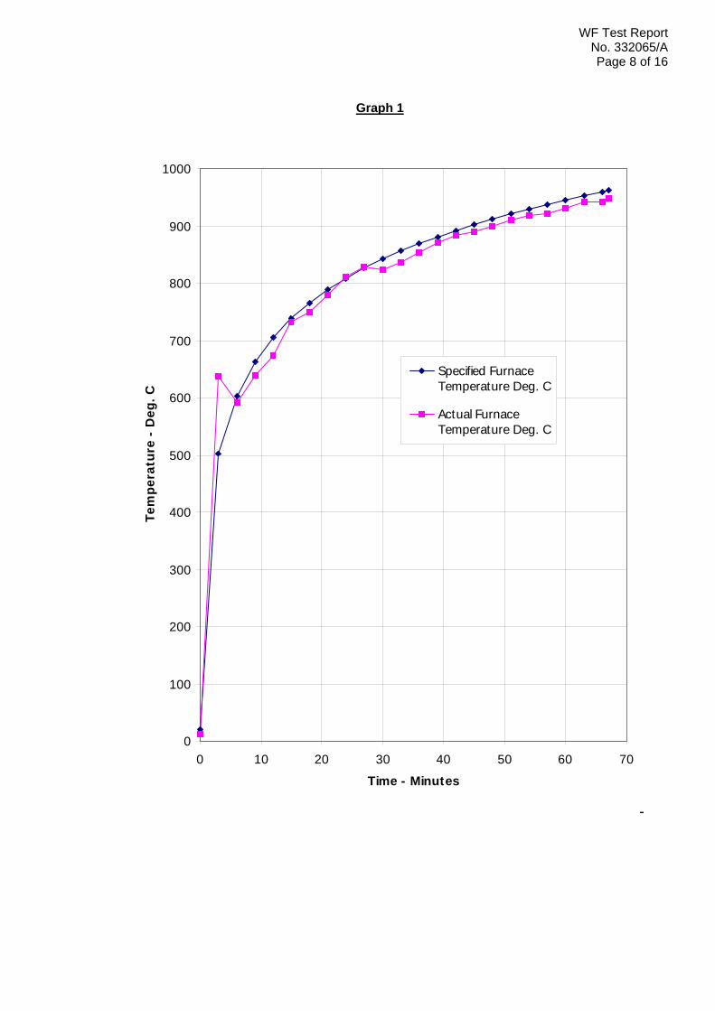
(Thermocouples 27 to 29) Graph 1 - Graph showing the specified and actual furnace temperatures

WF Test Report No. 332065/A
Page 3 of 16 Graph 2 - Graph showing the individual and mean temperatures recorded on the
unexposed surface of the floor. Observations on the general behaviour of the specimens during the test. Photographs taken before and after the test. The test was discontinued after a period of 90 minutes. We trust that the information obtained from the test will be useful to you. Yours faithfully,
Responsible Officer D. Yates Testing Officer Fire Resistance Department Exova Warringtonfire
This copy has been produced from a .pdf format electronic file that has been provided by Exova Warringtonfire to the sponsor of the report and must only be reproduced in full. Extracts or abridgements of reports must not be published without permission of Exova Warringtonfire. The pdf copy supplied is the sole authentic version of this document. All pdf versions of this report bear authentic signatures of the responsible Exova Warringtonfire staff.
WF Test Report No. 332065/A
Page 4 of 16
Table 1
Time Specified Actual Furnace Furnace
Minutes Temperature Temperature Deg. C Deg. C 0 20 26 3 502 481 6 603 595 9 663 653 12 705 698 15 739 741 18 766 766 21 789 785 24 809 806 27 826 827 30 842 843 33 856 857 36 869 870 39 881 880 42 892 892 45 902 902 48 912 912 51 921 922 54 930 931 57 938 941 60 945 945 63 953 956 66 960 964 69 966 967 72 973 970 75 979 981 78 985 986 81 990 991 84 996 994 87 1001 999 90 1006 1004

WF Test Report No. 332065/A
Page 5 of 16
Table 2
Time T/C T/C T/C T/C T/C Mean Number Number Number Number Number
Minutes 20 21 22 23 24 Temp Deg. C Deg. C Deg. C Deg. C Deg. C Deg. C 0 21 21 22 23 22 22 3 21 21 22 23 22 22 6 21 21 22 22 22 22 9 21 21 22 23 22 22 12 21 22 23 23 23 22 15 22 22 25 24 23 23 18 23 24 28 25 25 25 21 24 25 34 26 26 27 24 26 27 45 28 28 31 27 28 28 59 29 30 35 30 29 30 71 31 31 38 33 31 32 78 32 33 41 36 32 33 84 34 34 43 39 34 35 85 35 36 45 42 36 37 87 37 38 47 45 38 39 90 38 39 49 48 39 40 92 40 41 50 51 41 42 95 41 42 52 54 42 43 98 42 43 54 57 44 45 102 43 45 56 60 46 47 108 45 47 59 63 48 52 119 48 51 64 66 52 57 130 53 56 70 69 57 62 141 58 61 76 72 62 66 151 62 65 81 75 66 70 159 66 69 86 78 69 72 166 69 71 89 81 72 74 170 72 73 92 84 74 76 176 74 75 95 87 75 77 181 76 76 97 90 78 79 191 78 79 101
WF Test Report No. 332065/A
Page 6 of 16
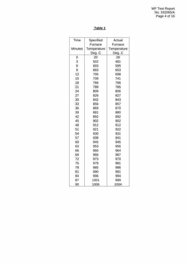
Table 3
Time T/C T/C Number Number
Minutes 25 26 Deg. C Deg. C 0 21 22 3 21 22 6 21 22 9 21 22 12 21 22 15 22 23 18 22 23 21 23 24 24 24 26 27 26 27 30 27 28 33 29 30 36 30 31 39 32 33 42 34 35 45 36 39 48 38 43 51 41 46 54 48 49 57 54 52 60 60 57 63 64 61 66 67 63 69 70 66 72 72 67 75 74 69 78 74 71 81 74 73 84 76 74 87 76 76 90 79 78
WF Test Report No. 332065/A
Page 7 of 16
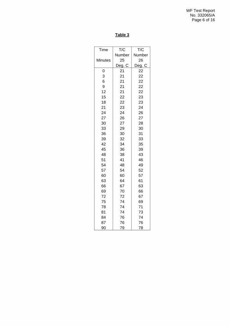
Table 4
Time T/C T/C T/C Number Number Number
Minutes 27 28 29 Deg. C Deg. C Deg. C 0 23 23 24 3 24 24 26 6 32 33 48 9 47 56 74 12 70 91 92 15 88 129 109 18 127 178 116 21 164 217 132 24 200 250 151 27 230 257 165 30 255 286 177 33 264 352 189 36 273 412 197 39 290 463 207 42 334 494 217 45 375 516 230 48 405 530 245 51 421 538 256 54 430 542 262 57 437 541 272 60 448 535 302 63 471 542 338 66 491 549 382 69 504 551 423 72 517 558 450 75 532 567 475 78 548 576 493 81 561 586 514 84 581 607 540 87 617 661 563 90 652 675 587
WF Test Report No. 332065/A
Page 8 of 16
Graph 1
0
100
200
300
400
500
600
700
800
900
1000
0 10 20 30 40 50 60 70
Time - Minutes
Tem
pera
ture
- D
eg. C
Specified FurnaceTemperature Deg. C
Actual FurnaceTemperature Deg. C

WF Test Report No. 332065/A
Page 9 of 16
Graph 2

WF Test Report No. 332065/APage 10 of 16
Test Observations
Time All observations are from the unexposed face unless noted otherwise.
mins secs The ambient air temperature in the vicinity of the test construction was 21ºC at the start of the test with a maximum variation of +4, -1ºC during the test.
00 00 The test commences.
04 30 Slight smoke release begins from the joints within the timber deck.
05 30 Viewed from the exposed face, the paper face of the plaster board ceiling has begun to burn away. The plastic speaker facing of Specimens A and B appears to have melted and fallen away.
06 00 Viewed from the exposed face, the plastic speaker facing of Specimen C appears to have melted and fallen into the furnace.
11 20 Slight smoke release continues from along the joints within the timber deck. Slight discolouration is evident at the same locations.
30 00 The ceiling board joints appear black in colour and slightly charred. The circular apertures within the ceiling appear blackened and slightly charred also.
50 00 The board joints within the first layer of ceiling board have opened up by approximately 20 – 25 mm.
58 40 Viewed from the exposed face, a large section of the first layer of ceiling board has dropped downwards by approximately 30 – 35 mm as it begins to detach from the ceiling along the joint.
62 10 Smoke release from the joints within the timber floor has increased slightly. Discolouration has become more evident at the same location.
64 30 Viewed from the exposed face, flames issue from the circular openings within the ceiling. The first layer of the ceiling board has dropped down further along the joint now by approximately 50 mm.
71 30 Smoke release from the joints within the timber deck has increased further.
72 10 Viewed from the exposed face, a large section of the first layer of ceiling board continued to pull away from the ceiling now by approximately 150 – 200 mm.
73 10 A large section of the first layer of ceiling board has detached and fallen into the furnace chamber.
75 00 Smoke release has increased further along the timber deck joints.
78 55 A cotton pad is applied at the mid span of a timber deck joint but fails to ignite.
83 20 Viewed from the exposed face, large amounts of flaming issue from the circular apertures within the ceiling.

WF Test Report No. 332065/APage 11 of 16
Time
mins secs
84 40 Smoke release from the joints within the timber deck has increased significantly.
89 50 A large section of the second layer of board begins to drop downwards at the approximate centre of the ceiling.
90 00 Smoke release from the ceiling increases significantly and the test is discontinued at the sponsor’s request.

WF Test Report No. 332065/APage 12 of 16
Test Photographs
The exposed face of the ceiling prior to the test.
The unexposed face of the ceiling prior to the test.

WF Test Report No. 332065/APage 13 of 16
The unexposed face of the ceiling after a test duration of 30 minutes
The exposed face of the ceiling after a test duration of 30 minutes
WF Test Report No. 332065/APage 14 of 16
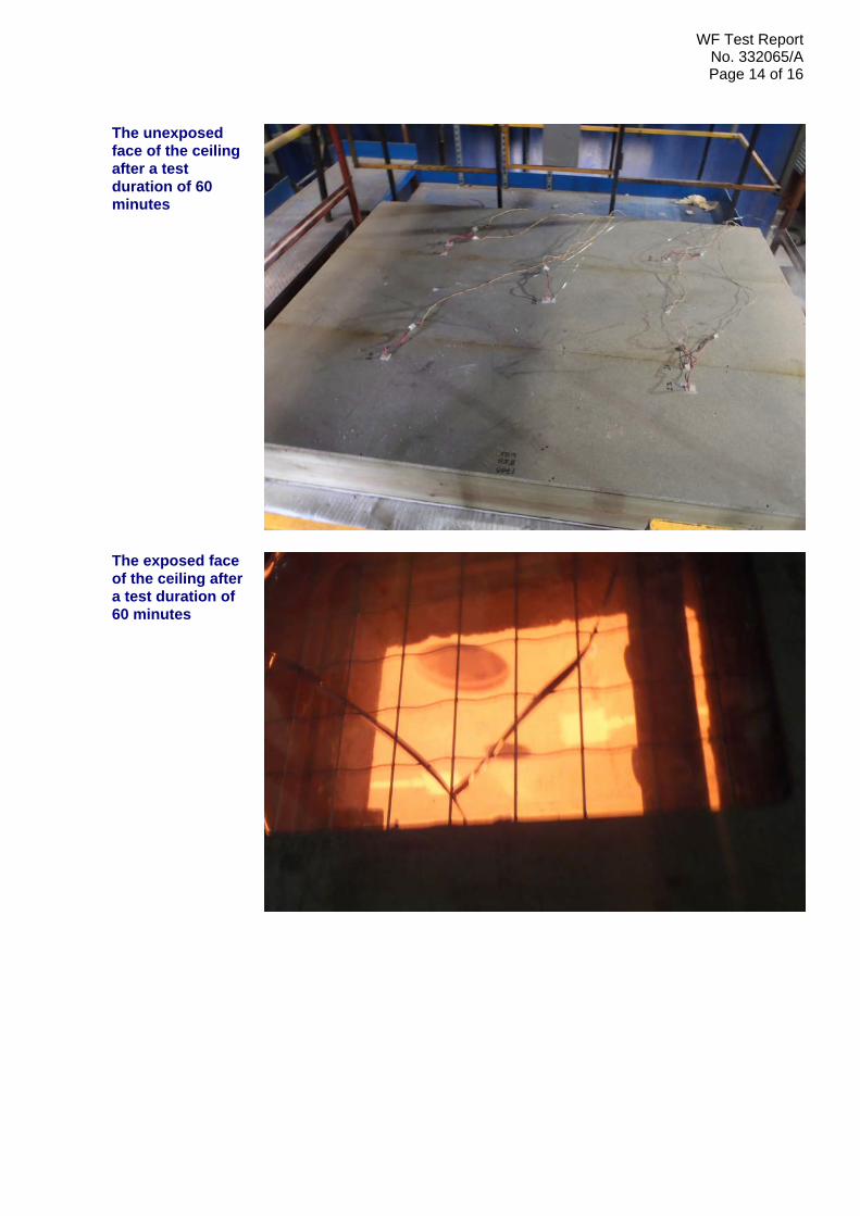
The unexposed face of the ceiling after a test duration of 60 minutes
The exposed face of the ceiling after a test duration of 60 minutes
WF Test Report No. 332065/APage 15 of 16
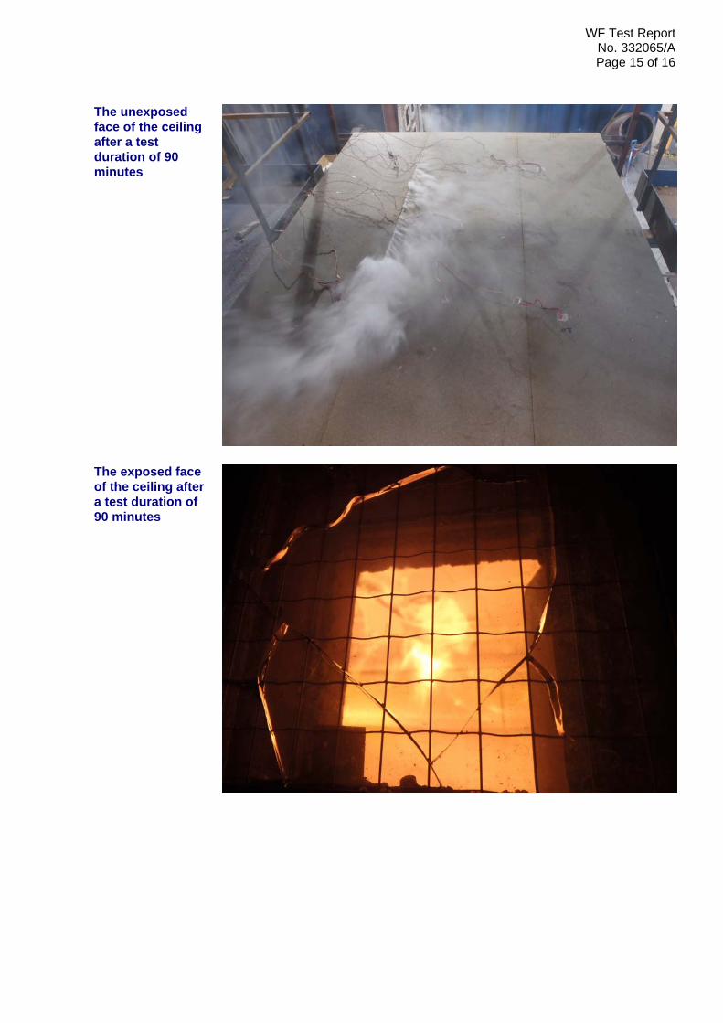
The unexposed face of the ceiling after a test duration of 90 minutes
The exposed face of the ceiling after a test duration of 90 minutes

WF Test Report No. 332065/APage 16 of 16
The exposed face of the ceiling immediately after the test

![[Frontiers in Bioscience S3, 1363-1389, June 1, 2011 ... · [Frontiers in Bioscience S3, 1363-1389, June 1, 2011] 1363 Advances in homeopathy and immunology: a review of clinical](https://img.pdfslide.us/doc/110x75/5f7b6db8a1e23576bf17bdb4/frontiers-in-bioscience-s3-1363-1389-june-1-2011-frontiers-in-bioscience.jpg)


![State Publications Accounting Archive 1925 Examination [1925]](https://img.pdfslide.us/doc/110x75/61cb235e0196bc3759718eb6/state-publications-accounting-archive-1925-examination-1925.jpg)