Embed Size (px)
Citation preview

Pro
vide
d by
: w
ww
.spi
c.ir
Standard Method of Test for
Surface Resistivity Indication of Concrete’s Ability to Resist Chloride Ion Penetration
AASHTO Designation: T 358-151
American Association of State Highway and Transportation Officials 444 North Capitol Street N.W., Suite 249 Washington, D.C. 20001
Copyright American Association of State Highway and Transportation Officials Provided by IHS under license with AASHTO Licensee=University of Texas Revised Sub Account/5620001114
Not for Resale, 11/11/2015 00:39:27 MSTNo reproduction or networking permitted without license from IHS
--``,``,,,,`,```,``````,,,,,,`-`-`,,`,,`,`,,`---
www.salmanco.comwww.salmanco.com
Pro
vide
d by
: w
ww
.spi
c.ir
TS-3c T 358-1 AASHTO
Standard Method of Test for
Surface Resistivity Indication of Concrete’s Ability to Resist Chloride Ion Penetration
AASHTO Designation: T 358-151
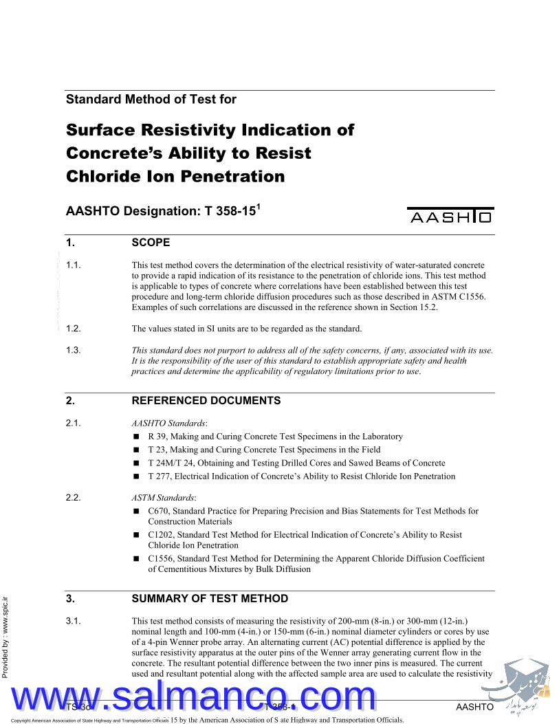
1. SCOPE
1.1. This test method covers the determination of the electrical resistivity of water-saturated concrete to provide a rapid indication of its resistance to the penetration of chloride ions. This test method is applicable to types of concrete where correlations have been established between this test procedure and long-term chloride diffusion procedures such as those described in ASTM C1556. Examples of such correlations are discussed in the reference shown in Section 15.2.
1.2. The values stated in SI units are to be regarded as the standard.
1.3. This standard does not purport to address all of the safety concerns, if any, associated with its use. It is the responsibility of the user of this standard to establish appropriate safety and health practices and determine the applicability of regulatory limitations prior to use.
2. REFERENCED DOCUMENTS
2.1. AASHTO Standards: R 39, Making and Curing Concrete Test Specimens in the Laboratory T 23, Making and Curing Concrete Test Specimens in the Field T 24M/T 24, Obtaining and Testing Drilled Cores and Sawed Beams of Concrete T 277, Electrical Indication of Concrete’s Ability to Resist Chloride Ion Penetration
2.2. ASTM Standards: C670, Standard Practice for Preparing Precision and Bias Statements for Test Methods for
Construction Materials C1202, Standard Test Method for Electrical Indication of Concrete’s Ability to Resist
Chloride Ion Penetration C1556, Standard Test Method for Determining the Apparent Chloride Diffusion Coefficient
of Cementitious Mixtures by Bulk Diffusion
3. SUMMARY OF TEST METHOD
3.1. This test method consists of measuring the resistivity of 200-mm (8-in.) or 300-mm (12-in.) nominal length and 100-mm (4-in.) or 150-mm (6-in.) nominal diameter cylinders or cores by use of a 4-pin Wenner probe array. An alternating current (AC) potential difference is applied by the surface resistivity apparatus at the outer pins of the Wenner array generating current flow in the concrete. The resultant potential difference between the two inner pins is measured. The current used and resultant potential along with the affected sample area are used to calculate the resistivity
© 2015 by the American Association of State Highway and Transportation Officials.All rights reserved. Duplication is a violation of applicable law.
Copyright American Association of State Highway and Transportation Officials Provided by IHS under license with AASHTO Licensee=University of Texas Revised Sub Account/5620001114
Not for Resale, 11/11/2015 00:39:27 MSTNo reproduction or networking permitted without license from IHS
--``,``,,,,`,```,``````,,,,,,`-`-`,,`,,`,`,,`---
www.salmanco.comwww.salmanco.com

Pro
vide
d by
: w
ww
.spi
c.ir
TS-3c T 358-2 AASHTO
of the concrete. The resistivity, in kilohms-centimeters (kΩ-cm), has been found to be related to the resistance of the specimen to chloride ion penetration.
4. SIGNIFICANCE AND USE
4.1. This test method covers the laboratory evaluation of the electrical resistivity of concrete samples to provide a rapid indication of their resistance to chloride ion penetration. Wenner probe measurements have shown good correlations with other electrical indication tests such as the T 277 and the ASTM C1202 tests. In most cases, the electrical resistivity results have shown good correlation with chloride exposure tests, such as ASTM C1556, on companion cylinders cast from the same concrete mixtures (see references in Sections 15.2, 15.4, and 15.5).
4.2. This test method is suitable for evaluation of materials and material proportions for design purposes, as well as for research and development.
4.3. The qualitative terms in the left-hand column of Table 1 should be used in most cases unless otherwise noted by the specifying agency. The numerical results (resistivity, in kΩ-cm) from this test method must be used with caution, especially in applications such as quality control and acceptance testing.
Table 1—Chloride Ion Penetration
Chloride Ion Penetration Surface Resistivity Test
100-by-200-mm (4-by-8-in.) Cylinder (kΩ-cm) a = 1.5
150-by-300-mm (6-by-12-in.) Cylinder (kΩ-cm) a = 1.5
High <12 <9.5 Moderate 12–21 9.5–16.5 Low 21–37 16.5–29 Very low 37–254 29–199 Negligible >254 >199
a = Wenner probe tip spacing
4.4. The details of the test method apply to 100-mm (4-in.) and 150-mm (6-in.) nominal diameter specimens. Other specimen diameters may be tested with appropriate changes to the Wenner probe tip spacing and the correction factor in the calculating equation. (See reference in Section 15.3.)
© 2015 by the American Association of State Highway and Transportation Officials.All rights reserved. Duplication is a violation of applicable law.
Copyright American Association of State Highway and Transportation Officials Provided by IHS under license with AASHTO Licensee=University of Texas Revised Sub Account/5620001114
Not for Resale, 11/11/2015 00:39:27 MSTNo reproduction or networking permitted without license from IHS
--``,``,,,,`,```,``````,,,,,,`-`-`,,`,,`,`,,`---
www.salmanco.comwww.salmanco.com

Pro
vide
d by
: w
ww
.spi
c.ir
TS-3c T 358-3 AASHTO
Figure 1—Four-Point Wenner Array Probe Test Setup
5. INTERFERENCES
5.1. This test method can produce misleading results when calcium nitrite has been admixed into a concrete. The results from this test on concrete mixtures including calcium nitrite indicate lower resistivity values, that is, lower resistance to chloride ion penetration, when compared to tests on identical concrete mixtures (controls) without calcium nitrite. However, long-term chloride diffusion tests indicate the concretes with calcium nitrite were at least as resistant to chloride ion penetration as the control mixtures. Note 1—Other admixtures might affect results of this test similarly. Long-term diffusion tests are recommended if an admixture effect is suspected.
5.2. Sample curing condition is known to affect the resistivity of the solution in the pore structure (see Section 15.4). Lime-water curing on average reduces resistivity by 10 percent.
5.3. Because the test results are a function of the electrical resistance of the specimen, the presence of reinforcing steel or other embedded electrically conductive materials may have a significant effect. The test is not valid for samples containing reinforcing.
5.4. Sample age may have significant effects on the test results, depending on the type of concrete and the curing procedure. Most concretes, if properly cured, become progressively and significantly less permeable with time.
© 2015 by the American Association of State Highway and Transportation Officials.All rights reserved. Duplication is a violation of applicable law.
Copyright American Association of State Highway and Transportation Officials Provided by IHS under license with AASHTO Licensee=University of Texas Revised Sub Account/5620001114
Not for Resale, 11/11/2015 00:39:27 MSTNo reproduction or networking permitted without license from IHS
--``,``,,,,`,```,``````,,,,,,`-`-`,,`,,`,`,,`---
www.salmanco.comwww.salmanco.com

Pro
vide
d by
: w
ww
.spi
c.ir
TS-3c T 358-4 AASHTO
5.5. The degree of water saturation and concrete temperature may have a significant effect on the electrical resistivity of concrete. A standardized conditioning procedure has been developed to minimize this effect.
5.6. Factors that are known to affect resistivity as well as chloride ion penetration include water/cement ratio, pozzolans, the presence of polymeric admixtures, air-void system, aggregate type, and degree of consolidation.
6. APPARATUS
6.1. Surface Resistivity Apparatus—Apparatus needs to be able to supply a flat-topped trapezoidal wave at a frequency of about 13 Hz and a pk-pk level with a nominal voltage limit of 25V pk-pk. Use a Wenner probe capable of an adjustment of the probe tip spacing to 38.1 mm (1.5 in.).
Figure 2—Surface Resistivity Apparatus with 4-Pin Wenner Probe Array
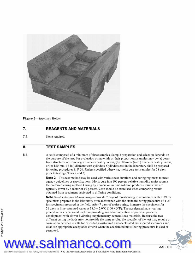
6.2. Specimen holder to prevent specimen rotation while under test. (See Figure 3 for example.)
© 2015 by the American Association of State Highway and Transportation Officials.All rights reserved. Duplication is a violation of applicable law.
Copyright American Association of State Highway and Transportation Officials Provided by IHS under license with AASHTO Licensee=University of Texas Revised Sub Account/5620001114
Not for Resale, 11/11/2015 00:39:27 MSTNo reproduction or networking permitted without license from IHS
--``,``,,,,`,```,``````,,,,,,`-`-`,,`,,`,`,,`---
www.salmanco.comwww.salmanco.com
Pro
vide
d by
: w
ww
.spi
c.ir
TS-3c T 358-5 AASHTO
Figure 3—Specimen Holder
7. REAGENTS AND MATERIALS
7.1. None required.
8. TEST SAMPLES
8.1. A set is composed of a minimum of three samples. Sample preparation and selection depends on the purpose of the test. For evaluation of materials or their proportions, samples may be (a) cores from structures or from larger diameter cast cylinders, (b) 100-mm- (4-in.) diameter cast cylinders, or (c) 150-mm- (6-in.) diameter cast cylinders. Cylinders cast in the laboratory shall be prepared following procedures in R 39. Unless specified otherwise, moist-cure test samples for 28 days prior to testing (Notes 2 and 3). Note 2—This test method may be used with various test durations and curing regimens to meet agency guidelines or specifications. Moist-cure in a 100 percent relative humidity moist room is the preferred curing method. Curing by immersion in lime solution produces results that are typically lower by a factor of 10 percent. Care should be exercised when comparing results obtained from specimens subjected to differing conditions. Note 3—Accelerated Moist-Curing—Provide 7 days of moist-curing in accordance with R 39 for specimens prepared in the laboratory or in accordance with the standard curing procedure of T 23 for specimens prepared in the field. After 7 days of moist-curing, immerse the specimens for 21 days in lime-saturated water at 38.0 ± 2.0°C (100 ± 3°F). The accelerated moist-curing procedure has been found useful in providing an earlier indication of potential property development with slower hydrating supplementary cementitious materials. Because the two different curing methods may not provide the same results, the specifier of the test may require a correlation between results for extended moist-cured and accelerated moist-cured specimens and establish appropriate acceptance criteria when the accelerated moist-curing procedure is used or permitted.
© 2015 by the American Association of State Highway and Transportation Officials.All rights reserved. Duplication is a violation of applicable law.
Copyright American Association of State Highway and Transportation Officials Provided by IHS under license with AASHTO Licensee=University of Texas Revised Sub Account/5620001114
Not for Resale, 11/11/2015 00:39:27 MSTNo reproduction or networking permitted without license from IHS
--``,``,,,,`,```,``````,,,,,,`-`-`,,`,,`,`,,`---
www.salmanco.comwww.salmanco.com
Pro
vide
d by
: w
ww
.spi
c.ir
TS-3c T 358-6 AASHTO
8.2. Transport the cores or field-cured cylinders to the laboratory in a moist condition in a sealed watertight container. If samples must be shipped, they should be packed to be properly protected from freezing and damage in transit or storage.
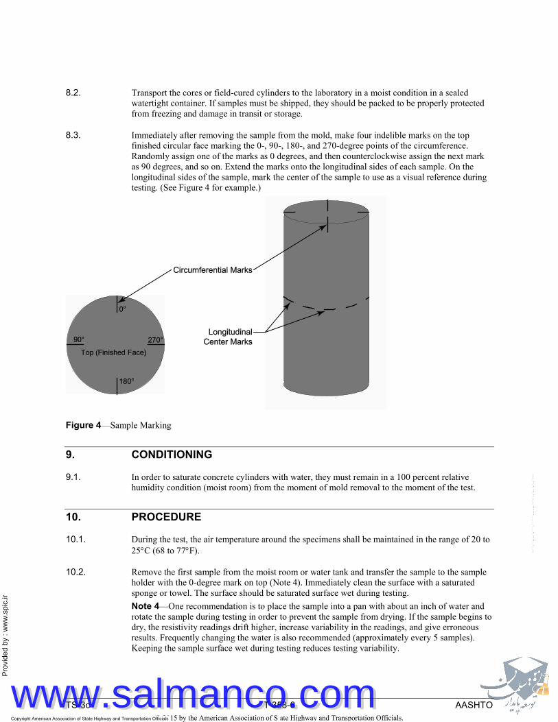
8.3. Immediately after removing the sample from the mold, make four indelible marks on the top finished circular face marking the 0-, 90-, 180-, and 270-degree points of the circumference. Randomly assign one of the marks as 0 degrees, and then counterclockwise assign the next mark as 90 degrees, and so on. Extend the marks onto the longitudinal sides of each sample. On the longitudinal sides of the sample, mark the center of the sample to use as a visual reference during testing. (See Figure 4 for example.)
Figure 4—Sample Marking
9. CONDITIONING
9.1. In order to saturate concrete cylinders with water, they must remain in a 100 percent relative humidity condition (moist room) from the moment of mold removal to the moment of the test.
10. PROCEDURE
10.1. During the test, the air temperature around the specimens shall be maintained in the range of 20 to 25°C (68 to 77°F).
10.2. Remove the first sample from the moist room or water tank and transfer the sample to the sample holder with the 0-degree mark on top (Note 4). Immediately clean the surface with a saturated sponge or towel. The surface should be saturated surface wet during testing. Note 4—One recommendation is to place the sample into a pan with about an inch of water and rotate the sample during testing in order to prevent the sample from drying. If the sample begins to dry, the resistivity readings drift higher, increase variability in the readings, and give erroneous results. Frequently changing the water is also recommended (approximately every 5 samples). Keeping the sample surface wet during testing reduces testing variability.
© 2015 by the American Association of State Highway and Transportation Officials.All rights reserved. Duplication is a violation of applicable law.
Copyright American Association of State Highway and Transportation Officials Provided by IHS under license with AASHTO Licensee=University of Texas Revised Sub Account/5620001114
Not for Resale, 11/11/2015 00:39:27 MSTNo reproduction or networking permitted without license from IHS
--``,``,,,,`,```,``````,,,,,,`-`-`,,`,,`,`,,`---
www.salmanco.comwww.salmanco.com

Pro
vide
d by
: w
ww
.spi
c.ir
TS-3c T 358-7 AASHTO
10.3. Place the Wenner array probe on the longitudinal side of the sample, making sure the longitudinal center mark is equidistant between the two inner probe pins. (See Figure 5.)
Figure 5—Wenner Array Placement
10.4. Record the measurement from the display unit after the reading becomes stable. (See Table 2 in Section 11.)
10.5. Rotate the sample from the 0- to the 90-degree mark, and repeat the steps in Sections 10.2 through 10.4.
10.6. Rotate the sample from the 90- to the 180-degree mark, and repeat the steps in Sections 10.2 through 10.4.
10.7. Rotate the sample from the 90- to the 270-degree mark, and repeat the steps in Sections 10.2 through 10.4.
10.8. Rotate the sample to the 0-degree mark and repeat the steps in Sections 10.3 through 10.7 for the sample in order to obtain a second set of readings at each degree mark. These will be used to obtain an average of two readings at each location.
10.9. Repeat the steps in Sections 10.1 to 10.8 for the other samples in the set.
© 2015 by the American Association of State Highway and Transportation Officials.All rights reserved. Duplication is a violation of applicable law.
Copyright American Association of State Highway and Transportation Officials Provided by IHS under license with AASHTO Licensee=University of Texas Revised Sub Account/5620001114
Not for Resale, 11/11/2015 00:39:27 MSTNo reproduction or networking permitted without license from IHS
--``,``,,,,`,```,``````,,,,,,`-`-`,,`,,`,`,,`---
www.salmanco.comwww.salmanco.com

Pro
vide
d by
: w
ww
.spi
c.ir
TS-3c T 358-8 AASHTO
11. CALCULATION AND INTERPRETATION OF RESULTS Table 2—Sample Table for Recording the Surface Resistivity Readings
Surface Resistivity (SR) Readings, kΩ-cm Sample 0° 90° 180° 270° 0° 90° 180° 270° Average
A
B
C Set average
Curing condition correction (× 1.1 lime tank or 1.0 for moist room) Penetrability based on test
11.1. Calculate the average resistivity and the percent relative standard deviation (%RSD) for each sample in the set. If the %RSD is above 7.5 percent, immerse the sample in a water bath (20 to 25°C (68 to 77°F)) for 2 h, and then repeat the test. If the %RSD on the second set is below 7.5 percent, use the last set of readings to compute the average. If the %RSD is greater than 7.5 percent, then average all 16 readings.
11.2. Calculate the average resistivity of the set.
11.3. If the samples were cured in a lime-water tank, multiply the set average by 1.1. If the samples were cured in a 100 percent relative humidity moist room, multiply the set average by 1.0.
11.4. Use Table 1, with the appropriate cylinder size, to evaluate the chloride penetration resistance based on the resistivity. These values were developed from data on various types of concretes.
12. REPORT
12.1. Report the following, if known:
12.1.1. Source of core or cylinder, in terms of the particular location the core or cylinder represents;
12.1.2. Identification number of core or cylinder;
12.1.3. Type of concrete, including binder type, water/cement ratio, and other relevant data supplied with samples;
12.1.4. Description of specimen, including presence and location of reinforcing steel;
12.1.5. Curing history of specimen;
12.1.6. Test results, reported as the surface resistivity measured; and
12.1.7. The qualitative chloride ion penetrability equivalent to the surface resistivity measured (from Table 1).
13. PRECISION AND BIAS2
13.1. Precision:
© 2015 by the American Association of State Highway and Transportation Officials.All rights reserved. Duplication is a violation of applicable law.
Copyright American Association of State Highway and Transportation Officials Provided by IHS under license with AASHTO Licensee=University of Texas Revised Sub Account/5620001114
Not for Resale, 11/11/2015 00:39:27 MSTNo reproduction or networking permitted without license from IHS
--``,``,,,,`,```,``````,,,,,,`-`-`,,`,,`,`,,`---
www.salmanco.comwww.salmanco.com

Pro
vide
d by
: w
ww
.spi
c.ir
TS-3c T 358-9 AASHTO
13.1.1. Single-Operator Precision—The single-operator coefficient of variation of a single test result has been found to be 6.3 percent (Note 5). Therefore, the results of two properly conducted tests by the same operator on concrete samples from the same batch and of the same diameter should not differ by more than 21 percent (Note 5).
13.1.2. Multilaboratory Precision—The multilaboratory coefficient of variation of a single test result has been found to be 12.5 percent (Note 5). Therefore results of two properly conducted tests in different laboratories on the same material should not differ by more than 35.2 percent (Note 5). Note 5—These numbers represent, respectively, the (1s percent) and (d2s percent) limits as described in ASTM C670. The precision statements are based on the variations in tests on three different concretes, each tested in triplicate in 11 laboratories. All specimens had the same actual diameters, but lengths varied within the range 50 ± 3 mm (2 ± 0.125 in.).
The percentage cited represents the (d2s percent) limit based on the value for the multilaboratory coefficient of variation.
13.2. Bias—The procedure of this test method for measuring the resistance of concrete to chloride ion penetration has no bias because the value of this resistance can be defined only in terms of a test method.
14. KEYWORDS
14.1. Chloride content; corrosion; deicing chemicals; resistance-chloride penetration.
15. REFERENCES
15.1. Chini, A. R., L. C. Muszynski, and J. Hicks. Determination of Acceptance Permeability Characteristics for Performance-Related Specifications for Portland Cement Concrete. Final Report (Contract No. BC 354-41) submitted to Florida Department of Transportation, Tallahassee, FL, July 2003.
15.2. Hamilton, H. R., A. J. Boyd, and E. A. Vivas. Permeability of Concrete—Comparison of Conductive and Diffusion Methods. Final Report (Contract No. BD 536) submitted to Florida Department of Transportation, Tallahassee, FL, June 2007.
15.3. Morris, W., E. I. Moreno, and A. A. Sagüés. “Practical Evaluation of Resistivity of Concrete in Test Cylinders Using a Wenner Array Probe” from Cement and Concrete Research, Vol. 26, No. 12, 1996, ScienceDirect, Elsevier, Amsterdam, The Netherlands, December 1996, pp. 1779–1787.
15.4. Kessler, R. J., R. G. Powers, and M. A. Paredes. “Resistivity Measurements of Water Saturated Concrete as an Indicator of Permeability, Paper 05261.” Corrosion 2005, conference held in Houston, TX, sponsored by NACE International, April 3–7, 2005.
15.5. Kessler, R. J., R. G. Powers, E. A. Vivas, M. A. Paredes, and Y. P. Virmani. “Surface Resistivity as an Indicator of Concrete Chloride Penetration Resistance.” 2008 Concrete Bridge Conference.
1 Formerly AASHTO Provisional Standard TP 95. First published as a full standard in 2015. 2 Supporting data have been filed at ASTM headquarters (100 Barr Harbor Drive, Conshohocken, PA 19428-2959) and may be obtained by requesting Research Report C-9-1004.
© 2015 by the American Association of State Highway and Transportation Officials.All rights reserved. Duplication is a violation of applicable law.
Copyright American Association of State Highway and Transportation Officials Provided by IHS under license with AASHTO Licensee=University of Texas Revised Sub Account/5620001114
Not for Resale, 11/11/2015 00:39:27 MSTNo reproduction or networking permitted without license from IHS
--``,``,,,,`,```,``````,,,,,,`-`-`,,`,,`,`,,`---
www.salmanco.comwww.salmanco.com