Embed Size (px)
Citation preview

www.gimatic.com98
09
/2
01
1
SZ
SZ32 SZ40
SZ12 SZ16 SZ25
PIN
ZE
PN
EU
MA
TIC
HE
PN
EU
MA
TIC
GR
IPP
ER
S
Pinze parallele a 2 griffe / 2-jaw parallel grippers
Pinza pneumatica a 2 griffe ad azione parallela
autocentrante (serie SZ)
• Azionamento a doppio effetto.
• Su richiesta con molla in chiusura.
• Meccanismo di autocentraggio brevettato.
• Diverse possibilità di fi ssaggio e alimentazione.
• Sensori magnetici opzionali.
SZ12 SZ16 SZ25 SZ32 SZ40
Fluido
Medium
Aria compressa fi ltrata, lubrifi cata / non lubrifi cata
Filtered, lubricated / non lubricated compressed air
Pressione di esercizio
Operating pressure range2 ÷ 8 bar
Temperatura di esercizio
Operating temperature range5° ÷ 60°C.
Forza di serraggio per griffa in apertura a 6 bar
Opening gripping force at 6 bar on each jaw25 N 45 N 115 N 190 N 310 N
Forza di serraggio totale in apertura a 6 bar
Opening total gripping force at 6 bar50 N 90 N 230 N 380 N 620 N
Forza di serraggio per griffa in chiusura a 6 bar
Closing gripping force at 6 bar on each jaw25 N 45 N 115 N 190 N 310 N
Forza di serraggio totale in chiusura a 6 bar
Closing total gripping force at 6 bar50 N 90 N 230 N 380 N 620 N
Corsa totale (±0.4 mm)Total stroke
8 mm 12 mm 20 mm 25 mm 30 mm
Frequenza max funzionamento continuativo
Maximum working frequency3 Hz 3 Hz 2 Hz 2 Hz 2 Hz
Consumo d’aria per ciclo
Cycle air consumption1 cm3 3 cm3 12 cm3 24 cm3 48 cm3
Tempo di apertura / chiusura senza carico
Opening / Closing time without load0.02 s 0.04 s 0.05 s 0.07 s 0.12 s
Peso
Weight0.094 kg 0.153 kg 0.446 kg 0.732 kg 1.135 kg
2-jaw parallel self-centering pneumatic gripper
(series SZ)
• Double acting.
• Spring closed, upon request.
• Patented self-centering system.
• Various options for fastening and feeding.
• Optional magnetic sensors.

www.gimatic.com 99
09
/2
01
1
SZ
SZ12 SZ16 SZ25 SZ32 SZ40
D H8 Ø7 Ø7 Ø9 Ø9 Ø12
D1 +0.2 Ø8 Ø8 Ø8 Ø15.6 Ø15.6
D2 +0.2 Ø10 Ø10 Ø10 Ø19 Ø19
D3 Ø4.3 Ø5.3 Ø6.3 Ø6.3 Ø8.3
D4 M4 M5 M6 M6 M8
D5 M5 M5 M5 1/8”G 1/8”G
D6 M4 M5 M6 M6 M8
H4 +0.02 13 15 24 29 35
H5 33.2 40.2 55 70.5 78.5
H6 5 5 7 7 9
H7 32.5 38.5 53 68.5 76.5
H8 9 12 15 19 19
H10 22 25 37 42 51
H11 31 37 51.5 67 75
L 59 71 102 117 146
L1 51 59 82 92 116
L2 52 63 92 105 130
L4 19.3 22.3 29.8 32.3 41.8
L5 11.4 13.5 21.4 26.4 31.4
L6 ±0.02 22 25 50 55 70
L7 38 45 73 84 104
L8 ±0.02 9 12 16 18 24
L9 ±0.05 14 17 23 25 33
L10 18 19 29 34 37
L11 10 11.5 18 20 22
P 6.5 6.5 11 11 15
P1 +0.1 1.6 1.6 2.1 2.1 2.6
P2 +0.2 1.8 1.8 1.8 3 3
P3 -0.2 2 2 2 1.3 1.3
P4 6.5 9 14 15 16
PIN
ZE
PN
EU
MA
TIC
HE
PN
EU
MA
TIC
GR
IPP
ER
S
Pinze parallele a 2 griffe / 2-jaw parallel grippers
Dimensioni (mm) / Dimensions (mm)
Ingresso aria
Aria compressa in P: apertura della pinza
Aria compressa in R: chiusura della pinza
apert
a /
chiu
sa /
Air connection
Compressed air in P: gripper opening
Compressed air in R: gripper closing
open
clo
sed

www.gimatic.com100
09
/2
01
1
SZP
INZ
E P
NE
UM
AT
ICH
EP
NE
UM
AT
IC G
RIP
PE
RS
Pinze parallele a 2 griffe / 2-jaw parallel grippers
Fissaggio
La pinza può essere montata in posizione fi ssa oppure su parti
in movimento: in questo caso va considerata la forza d’inerzia
cui la pinza ed il suo carico sono sottoposti.
Si può fi ssare su un lato o sul fondo.
Utilizzare 2 viti (S3) e 2 boccole di centraggio (B).
Fastening
The gripper can be fastened to a static or moving part.
When on a moving part, you must pay attention to the forces
created by inertia over the gripper and its load.
It can be fastened to one side or to the base.
Use 2 screws (S3) and 2 centering sleeves (B).

www.gimatic.com 101
09
/2
01
1
SZ
SZ12 SZ16 SZ25 SZ32 SZ40
B Ø7 H=3 Ø7 H=3 Ø9 H=4 Ø9 H=4 Ø12 H=5
B1 1.4 1.4 1.9 1.9 2.4
D Ø7 H8 Ø7 H8 Ø9 H8 Ø9 H8 Ø12 H8
S3 M4 M5 M6 M6 M8
P 6.5 6.5 11 11 15
H10 22 25 37 42 51
S6 M4 M5 M6 M6 M8
P4 6.5 9 14 15 16
PIN
ZE
PN
EU
MA
TIC
HE
PN
EU
MA
TIC
GR
IPP
ER
S
Pinze parallele a 2 griffe / 2-jaw parallel grippers
Costruire le dita di presa il più possibile corte e leggere.
Fissarle con 2 viti (S6) e 2 boccole di centraggio (B).
Nella confezione della pinza sono fornite 4 boccole di centraggio (B) per
le dita di presa e 2 boccole (B) per il corpo.
The gripping tools must be as short and light as possible.
They must be fastened by 2 screws (S6) and 2 centering
sleeves (B).
4 centering sleeves (B) for the gripping tools and 2 centering sleeves (B)
for the housing are supplied in the packaging.

www.gimatic.com102
09
/2
01
1
SZ
SZ40
SZ32
SZ25
SZ16
SZ12
PIN
ZE
PN
EU
MA
TIC
HE
PN
EU
MA
TIC
GR
IPP
ER
S
Pinze parallele a 2 griffe / 2-jaw parallel grippers
Forza di serraggio
I grafi ci mostrano la forza per griffa espressa dalla pinza
in funzione della pressione, del braccio di leva Z e del
disassamento del punto di presa X.
Forz
a se
rragg
io (N
) Fo
rza
serra
ggio
(N)
Forz
a se
rragg
io (N
) Fo
rza
serra
ggio
(N)
Forz
a se
rragg
io (N
)
apertura /apertura /
apertura /apertura /
apertura /apertura /
apertura /apertura /
apertura /apertura /
chiusura /chiusura /
chiusura /chiusura /
chiusura /chiusura /
chiusura /chiusura /
chiusura /chiusura /
La forza indicata
in questi grafi ci è
riferita alla singola
griffa.
La forza totale è il
doppio.
Gripping force
The graphs show the gripping force on each jaw, as a function
of the operating pressure, the gripping tool length Z and the
overhanging X.Gr
ippi
ng fo
rce
(N)
Grip
ping
forc
e (N
)Gr
ippi
ng fo
rce
(N)
Grip
ping
forc
e (N
)Gr
ippi
ng fo
rce
(N)
opening opening
opening opening
opening opening
opening opening
opening opening
closingclosing
closingclosing
closingclosing
closingclosing
closingclosing
The force shown in
these graphs refers
to one jaw.
The total force is
double.

www.gimatic.com 103
09
/2
01
1
SZ
SZ12 SZ16 SZ25 SZ32 SZ40
F s 30 N 70 N 100 N 300 N 600 N
Mx s 0.3 Nm 1.5 Nm 3 Nm 9 Nm 18 Nm
My s 0.2 Nm 1 Nm 2 Nm 6 Nm 12 Nm
Mz s 0.3 Nm 1.5 Nm 3 Nm 9 Nm 18 Nm
F d 0.6 N 1.4 N 2 N 4 N 6 Nm
Mx d 0.6 Ncm 3 Ncm 6 Ncm 12 Ncm 18 Ncm
My d 0.4 Ncm 2 Ncm 4 Ncm 8 Ncm 12 Ncm
Mz d 0.6 Ncm 3 Ncm 6 Ncm 12 Ncm 18 Ncm
m 0.3s - - 200 g 400 g 600 g
m 0.2s - 140 g 160 g 210 g 300 g
m 0.12s 60 g 120 g 140 g 180 g 240 g
m 0.07s 50 g 100 g 120 g 150 g -
m 0.05s 40 g 80 g 100 g - -
m 0.04s 30 g 60 g - - -
m 0.02s 20 g - - - -
PIN
ZE
PN
EU
MA
TIC
HE
PN
EU
MA
TIC
GR
IPP
ER
S
Pinze parallele a 2 griffe / 2-jaw parallel grippers
Carichi di sicurezza
Consultare la tabella per i carichi massimi ammissibili.
Forze e coppie eccessive possono danneggiare la pinza
e causare diffi coltà di funzionamento compromettendo la
sicurezza dell’operatore.
F s, Mx s, My s, Mz s, sono i carichi massimi ammissibili in
condizioni statiche, cioè con le griffe ferme.
F d, Mx d, My d, Mz d, sono i carichi massimi ammissibili in
condizioni dinamiche, cioè con le griffe in movimento.
Inoltre sono riportate le masse ammissibili (m) per ogni dito
di presa in funzione del tempo di apertura o chiusura. Usare
i regolatori di fl usso (non forniti) per ottenere la velocità
desiderata.
Safety loads
Check the table for maximum permitted loads.
Excessive forces or torques can damage the gripper, cause
functioning troubles and endanger the safety of the operator.
F s, Mx s, My s, Mz s, are maximum permitted static loads. Static
means with motionless jaws.
F d, Mx d, My d, Mz d, are maximum permitted dynamic loads.
Dynamic means with running jaws.
The following tables show the specifi ed maximum loads (m) on
each gripping tool as function of closing or opening time. Use
fl ow controllers (not supplied) to get the proper speed.
www.gimatic.com104
09
/2
01
1
SZ
SN....
SS....
OUT
OUT
PNP
NPN
Magneto-resistive
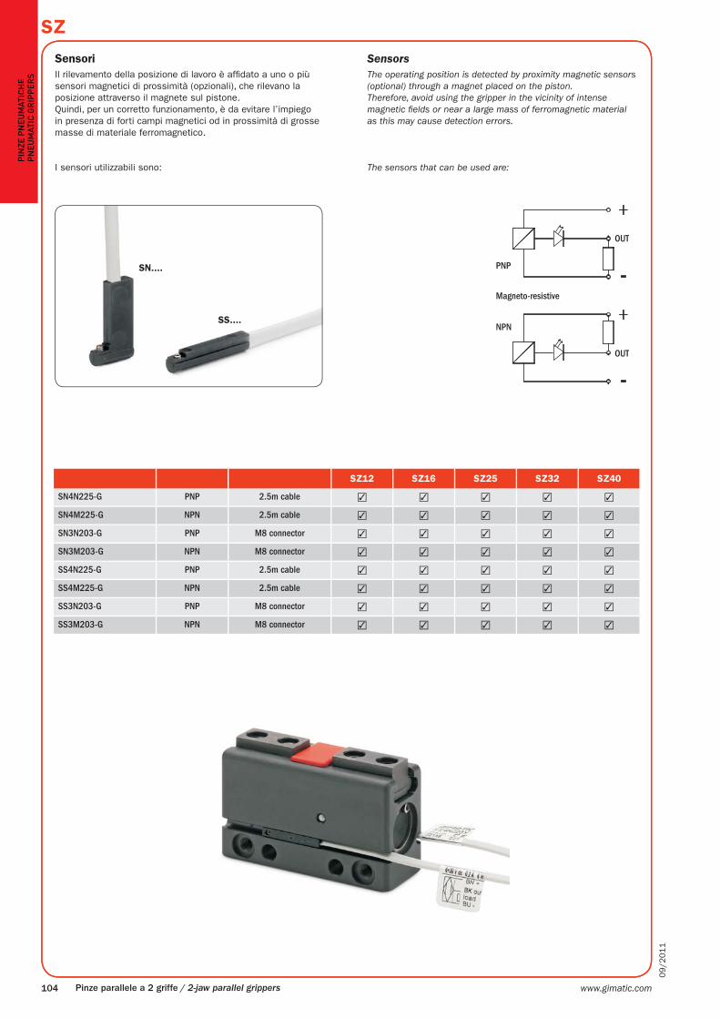
SZ12 SZ16 SZ25 SZ32 SZ40
SN4N225-G PNP 2.5m cable ✓ ✓ ✓ ✓ ✓
SN4M225-G NPN 2.5m cable ✓ ✓ ✓ ✓ ✓
SN3N203-G PNP M8 connector ✓ ✓ ✓ ✓ ✓
SN3M203-G NPN M8 connector ✓ ✓ ✓ ✓ ✓
SS4N225-G PNP 2.5m cable ✓ ✓ ✓ ✓ ✓
SS4M225-G NPN 2.5m cable ✓ ✓ ✓ ✓ ✓
SS3N203-G PNP M8 connector ✓ ✓ ✓ ✓ ✓
SS3M203-G NPN M8 connector ✓ ✓ ✓ ✓ ✓
PIN
ZE
PN
EU
MA
TIC
HE
PN
EU
MA
TIC
GR
IPP
ER
S
Pinze parallele a 2 griffe / 2-jaw parallel grippers
Sensori
Il rilevamento della posizione di lavoro è affi dato a uno o più
sensori magnetici di prossimità (opzionali), che rilevano la
posizione attraverso il magnete sul pistone.
Quindi, per un corretto funzionamento, è da evitare l’impiego
in presenza di forti campi magnetici od in prossimità di grosse
masse di materiale ferromagnetico.
I sensori utilizzabili sono:
Sensors
The operating position is detected by proximity magnetic sensors
(optional) through a magnet placed on the piston.
Therefore, avoid using the gripper in the vicinity of intense
magnetic fi elds or near a large mass of ferromagnetic material
as this may cause detection errors.
The sensors that can be used are:

www.gimatic.com 105
09
/2
01
1
SZ
G
H
E
R
F
P
SZ12 SZ16 SZ25 SZ32 SZ40
O-Ring Ø2.62x5.23 Ø2.62x5.23 Ø2.62x5.23 Ø1.78x15.6 Ø1.78x15.6
PIN
ZE
PN
EU
MA
TIC
HE
PN
EU
MA
TIC
GR
IPP
ER
S
Pinze parallele a 2 griffe / 2-jaw parallel grippers
Connessione pneumatica
La pinza si alimenta con aria compressa dai fori laterali (P e R)
montandovi i raccordi dell’aria ed i relativi tubi (non forniti).
Oppure si alimenta direttamente dai fori inferiori (G e H)
rimuovendo i tappi (E e F).
Aria compressa in P - H: apertura della pinza.
Aria compressa in R - G: chiusura della pinza.
La pinza è azionata con aria compressa fi ltrata (5÷40 μm) non
necessariamente lubrifi cata.
La scelta iniziale, lubrifi cata o non lubrifi cata, deve essere
mantenuta per tutta la vita della pinza.
L’impianto pneumatico deve essere pressurizzato
gradualmente, per evitare movimenti incontrollati.
Circuito pneumatico
Possibili inconvenienti sul circuito di alimentazione dell’aria
compressa:
1- Oscillazioni di pressione.
2- Riempimento pinza vuota all’avvio.
3- Improvvisa mancanza di pressione.
4- Velocità di azionamento eccessiva.
Accorgimenti per risolvere i problemi:
1- Serbatoio esterno (A).
2- Valvola di avviamento progressivo (B).
3- Valvole di sicurezza (C).
4- Regolatori di fl usso (D).
Compressed air feeding
The compressed air feeding can be accomplished on the lateral air
ports (P and R) with fi ttings and hoses (not supplied).
Or it can be accomplished directly by the bottom air ports (G and H)
removing the plugs (E and F).
Compressed air in P - H: gripper opening.
Compressed air in R - G: gripper closing.
The compressed air, must be fi ltered from 5 to 40 μm.
Maintain the medium selected at the start, lubricated or not, for the
complete service life of the gripper.
The pneumatic circuit must be pressurized progressively, to avoid
uncontrolled movements.
Pneumatic circuit
Possible problems on a compressed air circuit:
1- Pressure variation.
2- Pressurizing with empty cylinder.
3- Sudden pressure black-out.
4- Excessive speed of the jaws.
Possible solutions:
1- Compressed air storage (A).
2- Start-up valve (B).
3- Safety valve (C).
4- Flow controller (D).

www.gimatic.com106
09
/2
01
1
SZP
NE
UM
AT
IC G
RIP
PE
RS
Pinze parallele a 2 griffe / 2-jaw parallel grippers
Avvertenze
Evitare il contatto con sostanze corrosive, spruzzi di saldatura,
polveri abrasive, che potrebbero danneggiare la funzionalità
della pinza.
Per nessun motivo, persone od oggetti estranei devono entrare
nel raggio d’azione della pinza.
La pinza non deve essere messa in servizio prima che la
macchina di cui fa parte sia stata dichiarata conforme alle
disposizioni di sicurezza vigenti.
Manutenzione
La pinza va ingrassata ogni 10 milioni di cicli con:
• Molykote DX (parti metalliche);
• Molykote PG75 (guarnizioni).
I tappi 17 vanno rimossi solo se occorre smontare le parti
3 e 11.
Caution
Never let the gripper come into contact with corrosive
substances, soldering splashes or abrasive powders as they may
damage the gripper.
Never let non-authorized persons or objects stand within the
operating range of the gripper.
Never operate the gripper if the machine on which it is fi tted
does not comply with safety laws and standards of your country.
Maintenance
Grease the gripper after 10 million cycles with:
• Molykote DX (metal on metal);
• Molykote PG75 (gaskets).
The plugs 17 must be removed only if it is necessary to
disassemble the parts 3 and 11.

www.gimatic.com 107
09
/2
01
1
SZ
PIN
ZE
PN
EU
MA
TIC
HE
PN
EU
MA
TIC
GR
IPP
ER
S
Pinze parallele a 2 griffe / 2-jaw parallel grippers
Elenco delle parti / Part list
SZ12 SZ16 SZ25 SZ32 SZ40
1 Corpo pinza SZ12-01 SZ16-01 SZ25-01 SZ32-01 SZ40-01 Gripper housing 1
2 Griffa SZ12-02 SZ16-02 SZ25-02 SZ32-02 SZ40-02 Jaw 2
3 Leva SZ12-03 SH16-03 SZ25-03 SZ32-03 SZ40-03 Lever 3
4 Pistone SZ12-04 SH16-04 SZ25-04 SZ32-04 SZ40-04 Piston 4
5 Copertura SZ12-05 SZ16-05 SZ25-05 SZ32-05 SZ40-05 Cover 5
6 Tappo griffa SZ12-06 SH16-06 SZ25-06 SZ25-06 SZ40-06 Plug 6
7 Coperchio SZ12-09 GS-16-06 GS-25-06 SZ32-09 SZ40-09 End cap 7
8 Boccola SZ12-10 SZ16-10 SZ32-10 SZ32-10 SZ40-10 Bush 8
9 Magnete HP-12-7 PAR-16-10B PAR-25-10B FES-32-3-5 RAD-40-10 Magnet 9
10 Spina di riferimentoØ4x21.8
DIN 5402
Ø5x23.8
DIN 5402
Ø6x36
DIN 6325
Ø8x40
DIN 6325
Ø8x50
DIN 6325Dowel pin 10
11 Spina di riferimentoØ3x18
DIN 6325
Ø4x24
DIN 7
Ø6x36
DIN 6325
Ø6x40
DIN 6325
Ø8x50
DIN 6325Dowel pin 11
12 Spina di riferimentoØ2.5x20
DIN 6325
Ø3x24
DIN 6325
Ø5x36
DIN 6325
Ø5x40
DIN 6325
Ø6x50
DIN 6325Dowel pin 12
13 Guarnizione dinamica12.5x6.8x2.55
(GUAR-118)
16.5x9.8x2.55
(GUAR-119)
25x19x3.5
(GUAR-064)
32x24x3.5
(GUAR-063)
40x32x3.5
(GUAR-112E)Dynamic gasket 13
14 O-RingØ1.78x9.25
(GUAR-065)
Ø1x14
(GUAR-084)
Ø1.78x21.95
(GUAR-025)
Ø1.78x28.3
(GUAR-016)
Ø1.78x34.65
(GUAR-062)O-RING 14
15 Seeger Ø13 DIN 472 Ø17 DIN 472 Ø26 DIN 472 Ø33 DIN 472 Ø41 DIN 472 Snap-ring 15
16 Tappo 107-M5 107-M5 107-M5 107-G1/8 107-G1/8 Plug 16
17 Tappo DT-205 DT-205 DT-205 107-M5 107-M5 Plug 17
18 Boccola - - - SZ32-10 SZ40-10 Bush 18