Embed Size (px)
Citation preview
1
Systems of total capture and recycling of used organic and inorganic matter of selfsustainable human habitations. DESCRIPTION Background and Problems We are witnessing today a trend whereby human settlements on large tracts of the earth’s surface are retreating and disappearing. This trend has been attributed to the effects of global climate change causing the areas in question to become increasingly inhospitable due to lack of fresh water resources. Repeated periods of food shortage associated with drought in these areas are becoming commonplace. To reverse this trend new technologies are urgently required. To achieve this reversal, combinations of apparently diverse innovative technologies must be realised with a view to creating man-made “oases” in these areas:
1. Power generation based on solar energy with captive recycling of organic
and inorganic matter of the process. 2. Fluid purification systems to enable the long-term recycling and reuse of the fluids involved in the power generation and used within human habitats. 3. Processes for the economic desalination of sea and brackish water
especially to support human habitats in arid regions 4. Production facilities of human habitats
Despite the recent advances in sources of non-fossil renewable energy from wind, tides, hydroelectricity, etc. the most promising means for achieving an environmentally friendly source of power is to copy nature on a global scale by capturing and recycling the carbon emissions as fuel for further energy generation by directly tapping the rays of the sun for the required energy of conversion. Despite centuries of research and development the state of the art technology in the fields of photosynthesis and fluid purification technology is continuing to fail to solve the ever-increasing global pollution and degradation of the earth’s landmasses and their aqueous and atmospheric resources. Economically acceptable technologies for the large-scale production of photosynthesised hydrocarbons for energy generation and large-scale fluid purification in the nano/micro particle size range of naturally occurring and synthesized fluids are at present not forthcoming. Since Kyoto, interest in the field of applied photosynthesis has gained momentum and in particular by means of microalgae and cyanobacteria because of their extraordinary efficient utilisation of light and nutrient in the generation of biomass. With the exception of perhaps photovoltaic energy the only feasible usage of solar energy for present and future generations involves photosynthesis, i.e. the fixation of carbon dioxide by visible electromagnetic radiation from the
sun to form biomass in a space saving manner as a source of fuel. The terms “CARBON NEUTRAL” and “BIOFUELS” recently came into vogue to describe the concept of using such biomass as fuel for energy generation whereby the evolved CO2 is returned to the atmosphere for the generation of more carbohydrates by means of nature’s own photosynthesising process and whereby a steady state of CO2
concentration could conceivably be maintained in the atmosphere. The basic flaw with this concept is that with an ever-increasing demand for energy there is no practicable possibility for controlling the absolute value of the concentration of greenhouse gases and heat input in the atmosphere at any given time in view of the unpredictable natural fluctuations that have occurred in the past. The only possibility to correct this flaw is abandon the present concept of energy generation known as “carbon neutral” and replacing it with the concept “cyclic carbon capture”. The long existing warnings of coming acute shortages of clean air and fresh water on or near the surface of the earth are intimately connected in a causative manner with the present warnings concerning global warming. Global warming is just another symptom of a general worsening environmental crisis. The known amount of accessible fresh water has been put at approximately 0.01% of the total global water resources. The growing global practice of land-site filling with industrial and domestic waste-matter is already approaching crisis proportions. Conventional incineration technology has already proven not to be the answer. Large quantities of wasted emitted heat energy and the spread of diseases continue from the failure to provide sterile air on a large scale in the internal spaces of municipal, communal and domestic buildings. Worldwide there is a preconceived idea that the sealing off of all industrial sites from the environment will remain a distant dream. The chemical industry continues to be the major polluter of the global environment with toxic substances many of which even in trace amounts are lethal to all forms of life. The complete sealing of such plants must take priority on a global scale. These burgeoning problems are largely attributable to the failure of the traditional and conventional fluid purification technologies to provide effective and economic methods for large scale purification of fluids in the nano-micro range. The present failure to develop a photosynthesising solution to the increasing emissions of greenhouse gases can be attributed to the incapacity of today’s state of the art fluid purification to provide the necessary degree of sterility for large scale fluidic photosynthesising plants producing biomass. Testimony for this is the continued serious pollution of the global waterways despite the application of the best state of the art technology overseen by the world’s governmental pollution control authorities.
WO1internet2012X
PCT publication No.
WO2009023265 Applicant: Miller, Peter Anthony e-mail: [email protected]
2
The contemporary preoccupation with carbon and radioactive waste sequestration accompanying energy generation is at best sustainable only on the short term. This cannot be seen as a long term solution and is rather a short sighted palliative. By copying and even improving on nature’ s feat as well as improving the state of the art FLUID PURIFICATION TECHNOLOGY mankind can itself take control of its own environment.
Disclosed is a combination of interconnected innovative technologies to enable the realization of self-sustainable communities largely independent of outside man-made energy and potable water combined with ZERO fluid emissions into the environment that point the way to a sustainable solution of the global warming problem comprising large scale cyclic photosynthetic carbon capture and associated fluid purification systems with fluid recycling and solids’ recovery systems. THE INVENTION Power generation based on solar radiation with captive recycling of organic and inorganic matter of the process
Over the past century a considerable body of knowledge has accumulated from research concerning photochemistry and especially the reaction mechanism of solar photosynthesis. This knowledge comes mainly from research laboratories and institutions. For example there is a large volume of intellectual property relating to the construction and method of operation of laboratory bioreactors dealing with the handling of cell cultures related to photochemistry. This body of knowledge has influenced the more recent preoccupation with the possibility of using photosynthesis on an industrial scale to solve the global warming problem, whereby it must be kept in mind that attempts to date to scale up directly from laboratory to industrial sized processes has been fraught with difficulties. After decades of research and development there is still no record of a successful large-scale energy producing plant based on fuel provided by photosynthesized biomass. US 6667171 (Bayless) discloses a biologically based CO2 absorption apparatus and method for reducing emissions
from fossil burning units consisting of contained inclined framed membranes over which both flue gas and aqueous nutrient solution are caused to flow whereby photosynthesizing organisms such as algae and cyanobacteria grow on and adhere to the membranes. It is proposed to remove the layers of microorganisms at intervals by increasing the rate of flow of the impinging solution. A closed loop system for liquid and biomass transport that appears to be essentially a batch-wise operation is disclosed. This concept has its origin in laboratory scale experimentation. A method and means for the total purification and retrieval of the flue gas is not disclosed. In WO 03/094598 (Berzin) on p.52/53 claims are made for a system producing biomass from flue gas from conventional power stations and other combustion processes such as incinerators containing both particulate solids and gases (e.g. SOx and NOx) that are often damaging to biomass formation by known photosynthesizing means. Firstly the hot flue gas is blown through a contained quantity of wet biomass to cool the gas and dry the biomass whereby it is claimed that the concentration of particulate matter in the gas is reduced. The gas is then introduced to
the photobioreactors whereby it is claimed: ”The gas, upon passing through the photobioreactors is treated by the algae or other photosynthetic organisms therein to remove one or more pollutants therefrom, for example, CO2 and/or NOx. Treated gas containing a lower concentration of CO2 and/or NOx than the flue gas is released from gas outlets and in one embodiment is vented to the atmosphere. In other embodiments the photosynthetic organisms subsequently harvested from the bioreactor are processed and utilized as a fuel source for a combustion device such as a power plant generator or incinerator. The conclusion to be drawn from databases is that not only is this technology in its infancy but that the essential knowledge is ignored that when developing biologically based processes and then operating on an industrial scale the maintenance of a high degree of sanitation and often sterility throughout the whole process must take priority. The present disclosure takes this aspect seriously and is a centerpiece of the innovation. The scope of the invention
Figs.1-19 illustrate schematically the principles of the present invention, whereby carbon gases emitted from conventional power stations and other combustion processes are converted by photosynthesis to carbohydrates then hydrocarbons and recycled as fuel in captive closed systems thus completely eliminating emissions of green house gases to the atmosphere as well as providing the precondition for the establishment of selfsustainable human settlements. In cyclic processes CO2 emitted from the combustion unit is reduced to carbohydrates and oxygen in the photosynthesizing bioreactor units. The carbohydrates are converted to hydrocarbons in anaerobic digesters and fermenters. A constant quantity and ratio of carbon, hydrogen, oxygen and nutrients are thereby captured and recycled under near-sterile conditions to a power station forming a closed looped system with zero fluid emissions to the environment operating continuously and fully automatically. To achieve this an advanced system of fluid purification and water desalination is disclosed that is integrated into the process fluidic streams of the photosynthesizing, combustion, agricultural, horticultural, waste remediation facilities as well all the internal air environment and production facilities for biochemicals, chemicals, food, beverages and water all as parts of integrated selfsustainable human habitats.

3
CAPTIVE GLUCOSE-METHANE POWER CYCLE
Figs.1 illustrate a cyclic power generating system based on fuel provided by the photosynthesis of carbohydrates by the photo-fixation of carbon from the carbon dioxide in the flue gas of the power generator. The captive cyclic process is expressed by the following cyclic set of chain reactions (Fig.1a):
Fig.1a A) Combustion 3CH4 + 6O2 + 3CO2 > 6CO2 + 6H2O ----- I METHANE OXYGEN CARBON DIOXIDE WATER
B) Photosynthesis 6CO2 + 6H2O > C6H12O6 + 6O2 ----- II
CARBON DIOXIDE WATER GLUCOSE OXYGEN
C) Anaerobic digestion C6H12O6 > 3CH4 + 3CO2 ------- III GLUCOSE METHANE CARBON DIOXIDE. In Fig.1b the compact photobioreactor of the present invention operates in a continuous manner as apposed to the batch-wise operation of the state of the art thus reducing the crop area for power stations from square kilometers required by conventional farming to hectares with the method according to the invention. According to the present invention these photobioreactors consist of stacked photosynthesising batteries (p.3-5, Figs.1, 2, 3) providing a surface for photosynthesis in a translucent temperature controlled sealed space of 200 x 100 x10 m equivalent to a conventional “pond” area of 1 X 1 square kilometre – a ratio of 1: 50. Operation In Fig.1b hot gaseous emissions from the power station are first subjected to corona discharge (p.7, Fig.5) to electrically charge particulate matter after which they are removed by oppositely charged shuttle packed beds (p.10, Fig.12). After passing through condensers the cleaned cooled CO2 gas is pumped under positive pressure to seeding-bioreactors to which aqueous nutrients are recycled from anaerobic digesters by pumps through to the Miller universal fluid purifying plant. CO2 under continued positive pressure is absorbed and the seeding of photosynthesizing algal and/or bacterial microorganisms takes place. The seeded liquid is continuously transported by pumps under positive pressure through the photosynthesizing batteries first to storage settling tanks where the harvested photosynthesized microorganisms are recovered as a thick layer of slurry sediment. The clarified liquid is recycled to the seeding vessel for further growth of carbohydrates in the photobioreactor The thickened slurry is transferred to anaerobic digesters where the carbohydrate sediment is first comminuted and fluidized by hydrolysis (pH/enzymes) and then subjected to accelerated anaerobic biological decomposition for conversion to methane and carbon dioxide. After completion of the digestion process the turbid liquid is clarified with the aid of flocculating material. The issued methane (CH4) from
Fig.1b

4
the anaerobic digestion is first purified in the universal fluid purification plant and fed to the power generator with recycled oxygen from the photosynthesis for combustion.
CAPTIVE GLUCOSE-ALCOHOL POWER CYCLE
Figs.2 illustrates a further process whereby carbon dioxide emitted from the combustion unit is reduced to carbohydrates and oxygen in the photosynthesizing bioreactor unit. The carbohydrates are converted to alcohol in anaerobic fermenters. A constant quantity and ratio of carbon, oxygen, hydrogen and nutrients are thereby captured and recycled under sterile conditions on a power station forming a closed looped system with zero emissions to the environment operating continuously and fully automatically according to the following set of cyclic chemical reactions:
Fig.2a
The advantage of the CAPTIVE GLUCOSE-ALCOHOL POWER CYCLE lies in the minimal danger of contamination from damaging extraneous microorganisms in the nutrient solution of the captive cyclic process and the prospect of the conversion of the carbohydrates to hydrocarbons in hours instead of days or weeks. OPERATION In Fig.2b the harvest from the photobioreactor first undergoes sedimentation whereby the clarified supernatant nutrient is purified in the fluid purifying system and recycled to the seeding vessel of the photobioreactor and the thickened slurry layer of micro-algae is subjected to enzymatic hydrolysis whereby the algae mass is liquefied.
The liquefied algae in the enzymatic hydrolizer after purification in the fluid purification system is transferred to fermenters where fermentation of the saccharides with yeast is carried out. The yeast is finally subjected to sedimentation and the evolved carbon dioxide after passing through the fluid purification system is recycled to the photobioreactor. The clarified supernatant in the fermenters with an alcohol concentration of +10% is transferred to the distillation feed tank. Distillation is carried out to produce high percentage purified ethyl alcohol for use as fuel with recycled high purity oxygen from the photobioreactor. The overall advantages of this process are manifold: Firstly, the high degree of purity of the fluids at all stages of the process ensures the success of the process in long-term operation.
Fig.2b

5
Secondly, the combustion of ethanol with oxygen results in elevated combustion temperatures enabling an overall combustion efficiency of +60% - approximately twice that obtained with conventional air/fossil fuelled power stations. Thirdly, the products of combustion require minimal remediation before recycling to the photobioreactor.
Carbon and Nutrient Recycling of Biowaste generated from human communities and concomitant
agricultural and horticultural activities. The biowaste carbonaceous matter of contemporary human communities is causing an increasing embarrassment to industrialized societies. Incineration and landsite filling with the associated emission of polluting gases are ecologically unacceptable. According to the present invention illustrated in Fig.4 Biowaste of diverse origins is sorted, disintegrated and if necessary converted chemically for processing in bioreactors to carbon gases for forwarding to the power plant for energy production where the products of combustion are again purified, cooled and fed to contained agricultural facilities for photosynthesizing food crops wherewith the purified aqueous phase with captive nutrients of the process are recycled as irrigation.
This system is also the basis for the conversion of conventional carbon burning and carbon gas emitting power plants to carbon recycling systems the sustainability of which is also in large part dependent on the purification capability of the universal fluid purification system.
CLAIMS 1-6
1Captive cyclic processes enabling the creation of selfsustainable human habitats in previously uninhabitable and arid regions of the earth centring on the conversion of solar and light energy to biological matter by photosynthesising means, whereby in closed biological and physical
systems the quantities of organic and inorganic matter are conserved in an essentially captive condition by the application of
means for power generation and fuel production based solely on solar energy involving the captive recycling of organic and inorganic
matter of the process:
means for the captive purification and filtration of fluids of the processes whereby both purification (solutes-free), conservation of inorganic bio-nutrient (solutes-rich) fractions and solids recovery and reuse are carried out on a permanent basis; means for the photosynthesising desalination or sea and brackish water for make-up of potable water storage for animal consumption and use and means for containing biological processes whereby all fluids and waste biomass are recycled and reused on a permanent basis. 2. Captive cyclic process according to Claim 1 wherein the carbonaceous products of photosynthesis are represented as chains of glucose
molecules which are gasified under anaerobic conditions and combusted to produce power according to the set of cyclic chemical reactions
I, II, III (Fig.1a).
3.A photosynthesizing power generating system according to Claim 2 and Fig.1b whereby gas containing carbon dioxide from a combustion
process is first purified to remove contaminating by-products then pumped under pressure for absorption in seeding vessels from where the
seeded nutrient liquid pressurized with dissolved carbon dioxide is pumped under increased pressure by pumps through photo-bioreactors and
delivered to anaerobic digesters where in one embodiment the hydrocarbon harvest is first of all allowed to settle whereby the supernatant liquid
is removed by pump and passed through a purifying filtration system and recycled under pressure to the seeding vessels; whereby thickened
carbohydrate suspension is subjected to enzymatic and microbiological anaerobic digestion; wherewith the emitted methane and carbon dioxide
are passed through filters and fed by feed pumps to the power plant as fuel after which collected biosludge is separated into a liquid nutrient
**
biowaste
DISINTEGRATOR
FILTERS
BIOREACTORS
ENERGY FROM WASTE BIOMASS
paperplasticclothingsewagefoodanimal wastecrop rest
etc.wood
SYN
POWER
FILTER
TRANSMISSION
BIOWASTE
AGRO
~
users
e -
photo
to
WATER
4CH+
2CO
4CH
+
4CH+
2CO
2CO
CONVERTER
PLANT
H O2
AGRO.
+ 2CO
O2
Fig.4
R&D0408BB
6
fraction and recovered solids for recycling in the universal fluid purification and solids recovery system; whereby evolved oxygen is collected
under positive pressure from the photosynthesizing bioreactor and delivered to the power station by feed pump for the combustion and power
generating process.
4. Captive cyclic process according to Claim 1 wherein the carbonaceous products of photosynthesis are represented as chains of glucose
molecules that are liquefied under anaerobic conditions and combusted to produce power according to the set of cyclic chemical reaction
illustrated at Fig.2a.
5. A photosynthesizing power generating system according to Claim 4 and Fig.2b, whereby gas containing carbon dioxide from a combustion
process is first purified to remove contaminating by-products then pumped under pressure for absorption in seeding vessels from where the
seeded nutrient liquid pressurized with dissolved carbon dioxide is pumped under increased pressure by pumps through photo-bioreactors where
in one embodiment the hydrocarbon harvest is first allowed to settle whereby the supernatant liquid is removed by pump and passed through a
purifying filtration system and recycled under pressure to the seeding vessels; whereby thickened carbohydrate suspension is transferred to
enzymatic hydrolyzing vessels where the carbohydrates are liquefied and transformed into fermentable saccharides and smaller chained
hydrocarbons from which the contents are transferred to fermenters where after dosing with yeast fermentation takes place at an elevated
temperature whereby evolved carbon dioxide is purified and recycled to the photobioreactor after which the yeast content of the fermenters is
allowed to settle; whereupon the clarified supernatant is transferred to the feed tank of a distillation unit where high percentage alcohol is
recovered and pumped to the power generator for combustion with recycled oxygen from the photobioreactor.
6. A photosynthesising power generating process according to Claim 2 and Fig.4 whereby gas containing carbon dioxide from a combustion
process is first filtered to remove contaminating by-products then passed through a contained biological growth process and recycled as a
oxygen- rich carbon dioxide mixture to the power plant for the combustion process; whereby biomass from the contained biological growth
process is transported with other sources of biowaste to a disintegrator and converter and thence to anaerobic digesters where in one embodiment
the comminuted biomass is subjected to enzymatic and microbiological anaerobic digestion whereby the emitted methane and carbon dioxide are
passed through filters and fed to the power plant as fuel; whereby collected biosludge is separated into a liquid nutrient fraction and recovered
solids for recycling from the universal fluid purification and solids recovery system; whereby the purified and sterilized liquid nutrient is recycled
to the contained biological growth process as irrigation.
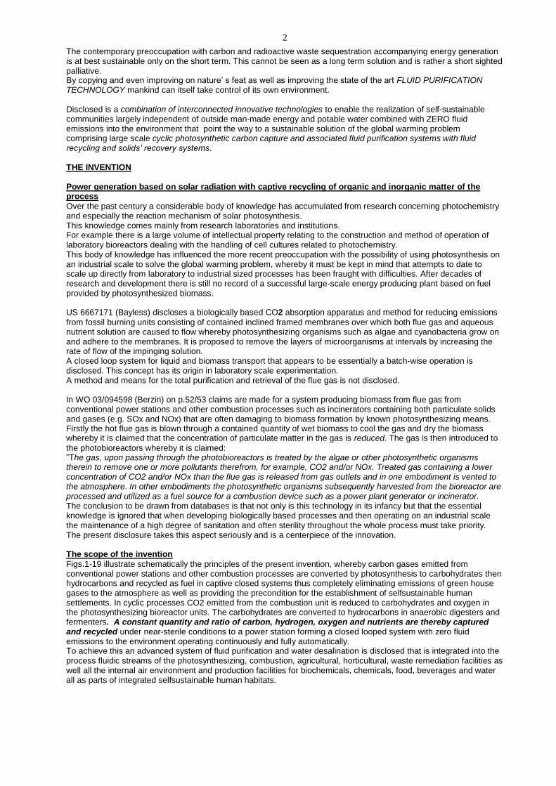
Fig.3 illustrates the preferred embodiment of stacked photo-batteries of the invention.
A battery consists of layers of stacked serpentine transparent conduits with lower inlet and upper outlet manifolds, the whole contained in transparent or internally reflecting housing. The individual batteries are designed for ease of dismantling for purposes of maintenance.
Claims 7-10 7.Apparatus according to Claims 3, 5 and Fig.3 wherein the units of photosynthesising bioreactors consist of packed transparent or translucent conduits adjacent to one another and connected in such a way that fluid under pressure can be introduced to one end and travel in a serpentine fashion to exit at the opposing end whereby the said fluid while in transport is subjected to the impingement of light radiation from an external source to initiate and promote a photosynthetic reaction in the said fluid.
Provision is made for the insertion of light emitting elements preferably fiber optics with a preferred emitted wave length range of 400-700 nm (nano-meter) between the individual fluid conducting conduits. Positive pressure is maintained in both the liquid and gaseous phases of the system during operation. The gases emitted and collected in the individual photo-batteries collect in upper contained spaces fitted with liquid level controllers allowing evolved gas from the batteries composed of oxygen and some residual carbon dioxide to be intermittently vented to the gas main from where it is pumped to the combustion chamber of the power generator.
7
6. Apparatus according to Claim 7, whereby a plurality of packed joined conduits are stacked one on top of the other sharing common fluid inlet and outlet manifolds and whereby fluids to undergo photosynthesis are introduced to a lower nozzle and exit through an upper nozzle joined to a gas escape valve mechanism. 9. Apparatus according to Claim 8, whereby individual units of a plurality of stacked, packed conduits are removable by lifting vertically for purposes of maintenance. 10. Apparatus according to Claims 7-9 and Ffgs.1b, 2b whereby a rows of a plurality of packed conduits making up photobioreactors are joined end to end.
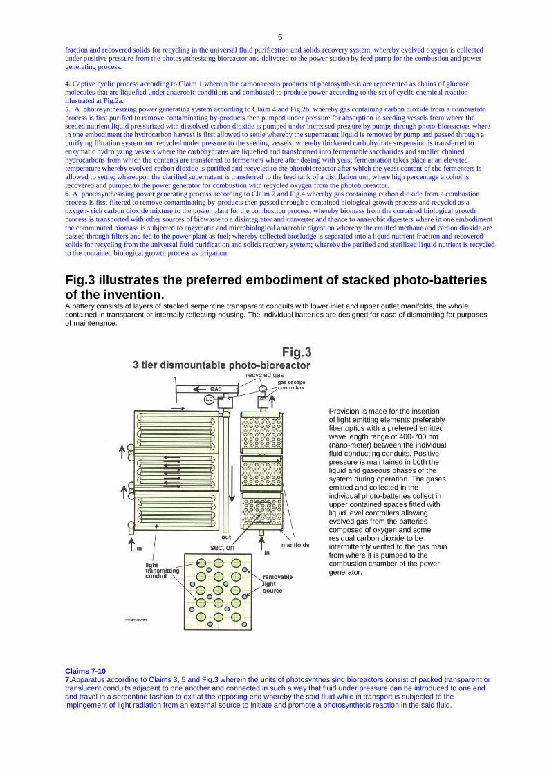
CAPTIVE SOLID FUEL POWER GENERATION Fig.5a represents a captive cyclic process consisting of the following set of chemical reactions:
A) Combustion C6H12O6 + 6O2 > 6CO2 + 6H2O------1V
GLUCOSE OXYGEN CARBON DIOXIDE WATER
B) Photosynthesis 6CO2 + 6H2O > C6H12O6 + 6O2 ---------V
CARBON DIOXIDE WATER GLUCOSE OXYGEN This process is also a basis for the conversion of conventional fossil fuel burning and carbon gas emitting power plants to captive carbon recycling systems the sustainability of which is also in large part dependent on the purification capability of the universal fluid purification system. In an embodiment illustrated in Fig.5b, the combustion of carbonaceous biomass from photo-bioreactors is represented in Fig.5a as a cyclic reaction of chains of glucose molecules directly combusted to produce power.
Biomass from the photo-bioreactor is retrieved in the filter/press/vacuum drier (Fig.17) that produces algal solid
fuel for the power station.
CLAIMS 11, 12 11. Process according to Claim 1 wherein the carbonaceous products of photosynthesis are represented as chains of glucose molecules which are directly combusted to produce power in a cyclic manner according to the following set of cyclic chemical reactions IV, V. (Fig.5a). 12. A photosynthesising power generating system according to Claim 11 and Fig.5b whereby gas containing carbon dioxide from a combustion process is first purified by subjecting the hot gas stream to corona discharge to electrostatically charge suspended particulate matter for removal by oppositely charged shuttle packed beds; whereby the purified gas stream is pumped under
Fig.17
Fig.5b
Fig.5a
8
pressure for absorption in seeding vessels from where the seeded nutrient liquid recycled as filtrate from the filter-press drier through the shuttle expanded elements fo the fluid purifying system pressurized with dissolved carbon dioxide and pumped under increased pressure through a photobioreactor to produce a suspension of carbohydrate that is delivered to the filter-press drier apparatus Fig.17 that produces a solid carbohydrate fuel for combustion with the recycled oxygen from the photobioreactor.
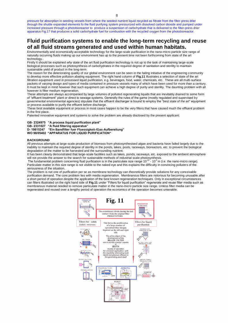
Fluid purification systems to enable the long-term recycling and reuse of all fluid streams generated and used within human habitats. Environmentally and economically acceptable technology for the large-scale purification in the nano-micro particle size range of naturally occurring fluids making up our environment has up to the present time not been forthcoming from state of the art technology.. Firstly it should be explained why state of the art fluid purification technology is not up to the task of maintaining large-scale biological processes such as photosynthesis of carbohydrates in the required degree of sanitation and sterility to maintain sustainable yield of product in the long-term. The reason for the deteriorating quality of our global environment can be seen in the failing initiative of the engineering community to develop more effective pollution abating equipment. The right hand column of Fig.11 illustrates a selection of state of the art filtration equipment used in processed liquid purification, e.g. beverages, food, water, chemicals, etc. These are all multi-surface packets of varying design and types of media contained in pressure vessels many of which have been used for more than a century. It must be kept in mind however that such equipment can achieve a high degree of purity and sterility. The daunting problem with all however is filter medium regeneration. These attempts are always accompanied by large volumes of polluted regenerating liquids that are inevitably drained to some form of “effluent treatment” plant or direct to sewage systems. Generally the rules of the game (mostly regulated and supervised by governmental environmental agencies) stipulate that the effluent discharger is bound to employ the “best state of the art” equipment or process available to purify the effluent before discharge. These best available equipment or process in most cases happen to be the very filters that have caused much the effluent problem in the first place. Patented innovative equipment and systems to solve the problem are already disclosed by the present applicant: GB- 2324975 “A process liquid purification plant” GB- 2331027 “A fluid filtering apparatus” D- 19815247 “Ein Bandfilter fuer Fluessigkeit-/Gas-Aufbereitung” WO 98/05402 “APPARATUS FOR LIQUID PURIFICATION“ BACKGROUND All previous attempts at large-scale production of biomass from photosynthesised algae and bacteria have failed largely due to the inability to maintain the required degree of sterility in the ponds, lakes, pools, raceways, bioreactors, etc. to prevent the biological degradation of the matter to be harvested and the surrounding nutrient. It has been clearly demonstrated that large-scale facilities such as lakes, ponds, raceways, etc. exposed to the ambient atmosphere will not provide the answer to the search for sustainable methods of industrial scale photosynthesis. The fundamental problem concerning fluid purification is in the particulate size range 10
-10 - 10
-5 m (i.e. the nano-micro range).
Particulate matter in this size range is not visible to the naked eye and this explains the difficulty in convincing polluters of the seriousness of the situation. The problem is not one of purification per se as membrane technology can theoretically provide solutions for any conceivable purification demand. The core problem lies with media regeneration. Membranous filters are notorious for becoming unusable after a short period of operation despite the application of the best known regeneration techniques. Only in exceptional circumstances can filters illustrated on the right hand side of Fig.11 under “Filters for liquid purification” regenerate and reuse filter media such as membranous material needed to remove particulate matter in the nano-micro particle size range. Unless filter media can be regenerated and reused over a lengthy period of operation the economics of the operation becomes untenable.
Fig. 11

9
The progenitor of all filtration apparatus the “NUTSCHE” filter (fFig.11) with a single horizontal filter surface was largely replaced during the 20
th century by the development of the vertical multi-planar FILTER PRESS for universal application. This led to the
evolutionary division of the further development into two distinct branches: Filters for fluid purification and Filters for solids recovery
Filters for liquid purification In the further evolution of the FILTER PRESS during the 20
th century the exposed multi-planar elements were simply encased in
pressure vessels resulting in an enormous proliferation of varying designs based on this configuration and an ever increasing pollution of the environment due to large volumes of liquid used in attempts at freeing blocked media after the filtration operation proper. Large quantities of varieties of filter aid powders used to solve the media blocking problems became a further part of the problem when flushed down the drains saturated with products containing an enormous range of polluting matter. More than any other causal effect it is the continued reliance on these and similar types of apparatus to solve the global fluid purification problems that is causing much of the present state of global environmental pollution and explains why such an obvious solution to the climate change problem as the growth and harvesting of algal biomass has not yet been realised on a large scale. THE SOLUTION: :A single complete processing and purification system for fluids (liquids and gases) whereby a universally applicable fluid purification and separation system plays the central role in fluid processing for the realisation of advanced human habitats. The solution involves
the physical separation of the operations of purification (filtration) and media regeneration for both deep bed and membrane purification;
the provision of a process for the regeneration and reuse of powdered and granular filter media. Effective media regeneration requires the possibility of the application of a large variety of effective optional processes including high pressure jets of washing fluids, backwashing, chemical cleaning procedures, vibration and ultrasonics. Because of the dangers of product contamination the choice of possible in situ regeneration procedures with state of the art filter equipment is extremely limited. By means of the present disclosed “shuttle” concept, the filter packs after the filtration/purification operation are moved to specially designed regeneration zones while simultaneously a freshly regenerated pack is positioned by the common belt in the “purification zone” to continue the operation. Fig.6a is a schematic representation of a large-scale universally applicable fluid purification system according to the present invention,
Stage 1: SHUTTLE PACKED BED PRESSURE BELT FILTER Stage 2: SHUTTLE EXPANDED SURFACE PRESSURE BELT FILTER Stage 3: SOLIDS RECOVERY AND LIQUID RECYCLING SYSTEMS Stage 4: COUNTER-CURRENT BED REGENERATION SYSTEM
conceived to solve the above described problematic. Further details of background design and operation are disclosed in GB2280857, GB2331027, GB2323852, GB2324975, D-1985247 and WO98/05402.
x
Fig.6a
gbshutgasunivbbbxxb
*
1
2
34
STAGESSHUTTLE DEEP BED PURIFICATION
FILTER MEDIUM REGENERATION
solids
liquid purifying additives
610
1
2
3
4
608
607
605
611
609
612
613
617614
616
615
618
SOLIDS RECOVERY / RECYCLING
SHUTTLE NANO-MICRO PURIFICATION

10
Stage 1 is a shuttle unit (Fig.12), consisting of twin regenerative mobile electro-charged packed layered beds of particulate matter for the purification of both liquids and gases in the range >0.01 micron. Liquids are generally pre-dosed with flocculating or coagulating substances whereas gases are pre-radiated with corona-discharge or its equivalent. Operation: The central purification chamber 605, reserved for fluid purification, contains a regenerated packed bed from the previous cycle transferred on the belt from the bed regeneration chamber (right). Chamber 604 (left) contains the exhausted packed bed for regeneration previously in 605. Liquid for purification dosed with flocculating or coagulating material from 608 or gas pre-radiated with corona discharge or its equivalent to electro-statically charge aerosols and suspended particulate matter is pumped by 607 through the bed in 605 in an oppositely charged state and delivered as purified or partially purified fluid to 610 in Stage 2 for more intensive final purification. Bed regeneration: Simultaneously the exhausted bed (left) is subjected to backwashing with recycled purified liquid from vessel 615 in Stage 3. Further combinations of regenerative measures (not shown) such as bed treatment with ultrasonic vibration and facilities for washing the beds with acids, alkalis, solvents and bed drying with heated gas or vapour are also available for application The used backwash or cleaning liquid is collected in 617 dosed with purifying agents from 608 for purification/filtration in 614 and collected as filtrate in 615. After purification and bed regeneration in Stage 1 the zones are opened and the band, moving in the opposite direction (shuttle-mode), delivers the exhausted bed in 605 to the empty right hand chamber and the regenerated bed on the left to 605 for the following cycle..
- The cycle is then repeated -
Stage 2 is a shuttle unit consisting of a twin regenerative mobile sets of extended surface filter elements (Fig.13) fitted with membranous or woven media for the separation of particulate matter in the nano-micro size range often acting as support for powdered or granular layers of pre-coated material such as kieselguhr, silica, “perlite”, glass fibre, cellulose fibres, etc. with a mean particulate size range of 30 micron often with the addition of finely ground purification material such as activated carbon, ion-exchange resins, etc. with a size range of 1-5 micron to facilitate its removal in the precoat regeneration operation in Stage 4.. Optionally, Stage 1 with packed bed members can also act as support for layers of pre-coated filteraid whereby separation of particulate matter in the size range 0.001-0.1 micron for certain operations is achievable. Operation External unfiltered fluid or partially purified fluid filtrate from 605 Stage 1 is delivered to the shuttle filter chamber 610 Stage 2 through regenerated extended surface filter elements fitted with membranous medium or through layers of regenerated surface-charged powdered or granular material covering the surface of the membranous filter elements. The purified fluid filtrate, now in a sterile condition, is delivered to its destination through conduit 613 (Fig.6).

11
Simultaneously the previously exhausted shuttle element now in 609 (Fig.6) is subjected to a variety of regeneration options including jets of high-pressure fluid, vibration, ultra-sonic generation, chemical treatment and backwashing. Stage 4 is the preferred apparatus and method of the present invention for the regeneration of precoated powder or granular purification media for both Stage1 and Stage 2 described above. This process is the key to successful high purity (sterile) operations in the proposed systems for algal photosynthesising operations. It provides a cost-effective method of providing a high degree of sterility for large scale biologically based operations. Operation: This novel unit operation can be described as batch-wise counter-current washing. 1
st Reslurrying of the bed
Referring to Fig.14 the filter beds from zone A are removed in either chamber B or C by high pressure jets of liquid and collected in regeneration vessel D (Stage 4).
Operation Decant-liquid in (1) from the previous batch is transferred to D into which, with agitation, the bed is discharged as a slurry from Stage1 or 2. The contents of D after pH-adjustment and dosing with purification agents are vigorously agitated for a set period.
Settling and Decantation With the agitator shut down the bed is allowed to settle to the base of D. The supernatant liquid, containing most of the dislodged adsorbed and trapped impurities in the bed material, is decanted to the turbid liquid purifier J.
2nd
Reslurrying of bed The contents of 2 are transferred to D where the bed is reslurried again by means of agitation. After a set time agitation ceases and the bed settles in the base and the supernatant liquid is transferred to 1.
3rd Reslurrying of bed
The contents of 3 are transferred to D where the bed is again reslurried by means of agitation. After a set time agitation ceases and the bed settles in the base of D and the supernatant liquid is transferred to 2.
4th Reslurrying of bed
The contents of 4 are transferred to D where the bed is again reslurried by means of agitation. After a set time agitation ceases and the bed settles in the base and the supernatant liquid is transferred to 3. According to requirements this batch-wise counter-current regeneration operation can be carried out with any number of (n) stages.
The final nth reslurrying operation
uses the stored purified liquid from J..
Purification and recycling of the 1st decant liquid in J:
pH-adjustment of decant from the 1st reslurrying in J (H2SO4 / NaOH).
Conditioning flocculating and/or coagulating agents are dosed from storage L. After a settling period the supernatant liquid is transferred to the final stage container n. The settled sludge is transferred to sludge container 617 (Fig.6).
The regenerated powdered or granular media, after reslurrying in 612 and pH adjustment to recharge the bed media, are recycled on 610 (or on 605) for redeposition on the surfaces of the purification members.
Stage 3 consists of a fluid residue purification apparatus 614 consisting of a moveable filter band arranged to move intermittently between two or more separately located sealing elements and two or more plane, pervious support member, a gas pump 616 and filtrate recycling apparatus 615 and a source of expendable non-woven filter material in roll form. Solids residue as well as product solids are recovered from suspension in this unit and collected in 618. Liquid suspensions from the regeneration of shuttle fluid purification members are purified and recycled to Stage 1 and Stage 2 from this stage for further member regeneration purposes thus achieving an essentially captive cyclic process. Fluid processing The previously described system can be applied not only for the purpose of the photosynthesis processes but also for general fluid processing operations for supplying human habitats with beverages, food, basic chemicals, as well as a large variety of unit operations such as:
Adsorptive fluid purification Extraction Catalysis Ion-exchange Liquid-gas reactions Packed beds containing granular activated carbon, silica gel, “Bentonite”, etc. are used for adsorptive fluid purification followed by bed regeneration. The overriding advantage is that separate purification and regeneration facilities enables a more thorough regeneration with the avoidance of product contamination and environmental pollution.
FEEDultra-sonicgen.
filter aid regenerationc/c
filtrate
MILLER BED REMOVAL & REGENERATION
WEBPLEATSHUT1
AB C
D J1 2 3 4
Fig. 14

12
CLAIMS 13-17 13. Processes according to Claim 1, wherein the fluid purification and solids recovery and recycling apparatus and systems comprise filter bands arranged to intermittently move over plane, pervious support members, whereby in the stationary stage elements vertically moveable with respect to the pervious support member engage the periphery of he stationary filter band to seal an overlying section, thereby forming a space into which fluid is delivered and allowed to exit through the section of filter band by means of pressure differential whereby the section of filter band consists of a fluid purification member integral with the upper plane of the sealed section of stationary filter band or carries solids’ material deposited on the section of the stationary filter band that is transferable by the band to one or more separately located planar pervious support members enabling further distinctive operational procedures to be carried out with the purification member or the deposited solids’ material. 14. Fluid purification apparatus and recycling systems according to Claims 1 and Fig.6a wherein the fluid purification members are integral with sealed sections of the filter band and the systems consist of four separate stages taking the form of shuttle packed beds, shuttle expanded elements, filter aid regeneration unit and a residue filtration unit. 15. Fluid purification apparatus and system according to Claim14 and Fig.14 whereby means consisting of counter-current solids washing operations of used filter beds of filter aid materials deposited on the surfaces of the expanded filter elements 610 (stage 2) and packed bed members 605 (stage 1) after removal are regenerated at 612 (stage 4) whereby the regenerated filter aids are redeposited in stages 1, 2 and the regenerating liquid is purified at stage 3 and recycled to stages 1 and 2 for further filter pack backwashing and bed removal. 16. Filter aid counter-current washing and regeneration system according to Claim 15,whereby in a batchwise operation shown as a succession of agitation/settling operations using vessels 1-n filter beds are freed of impurities and finally recycled as a suspension for reforming on the surfaces of the expanded filter elements and packed bed members. 17. Fluid purification apparatus and solids recovery system according to claims 13-16 and Fig.5b where in particular with gas purification operations, the incoming gas is preradiated with corona-discharge or its electrical equivalent to charge aerosols and suspended particulate matter in the said gas before passing through beds of granular or powdered material supported by expanded filter elements and packed bed members provided with an opposite electrostatic surface charge.
Process for the economic desalination of sea and brackish water to sustain human settlements in arid regions of the planet. Background We are witnessing today a trend whereby human settlements on large tracts of the earth’s surface are retreating and disappear ing. The chart Fig.16 illustrates the fact that over half of the earth’s land mass is largely devoid of thriving human settlements. Much of the territory including North and South Africa, the Middle East, West Americas, Middle Asia, southern Europe, Australia, parts of North and South America is almost continually bathed in sunlight during daylight hours and in proximity to sea or brackish ground water. Alone the generation of power by photosynthesis or other means cannot support sizeable human habitats in these regions without access to sources of fresh water. State of the art desalination processes such as multi-effect evaporation and reverse osmosis need high capital investment and energy consumption. Their installation and use are largely restricted to fossil fuel rich areas of the world and are accompanied either directly or indirectly by considerable emissions of green house gases and waste aqueous discharge from pre- and post-water treatment plants. Solution Fig.7 illustrates a simplified version of a photosynthetic captive carbon power generating scheme indicating how carbohydrate generated by photosynthesis from carbon dioxide by the action of solar radiation is converted to
13
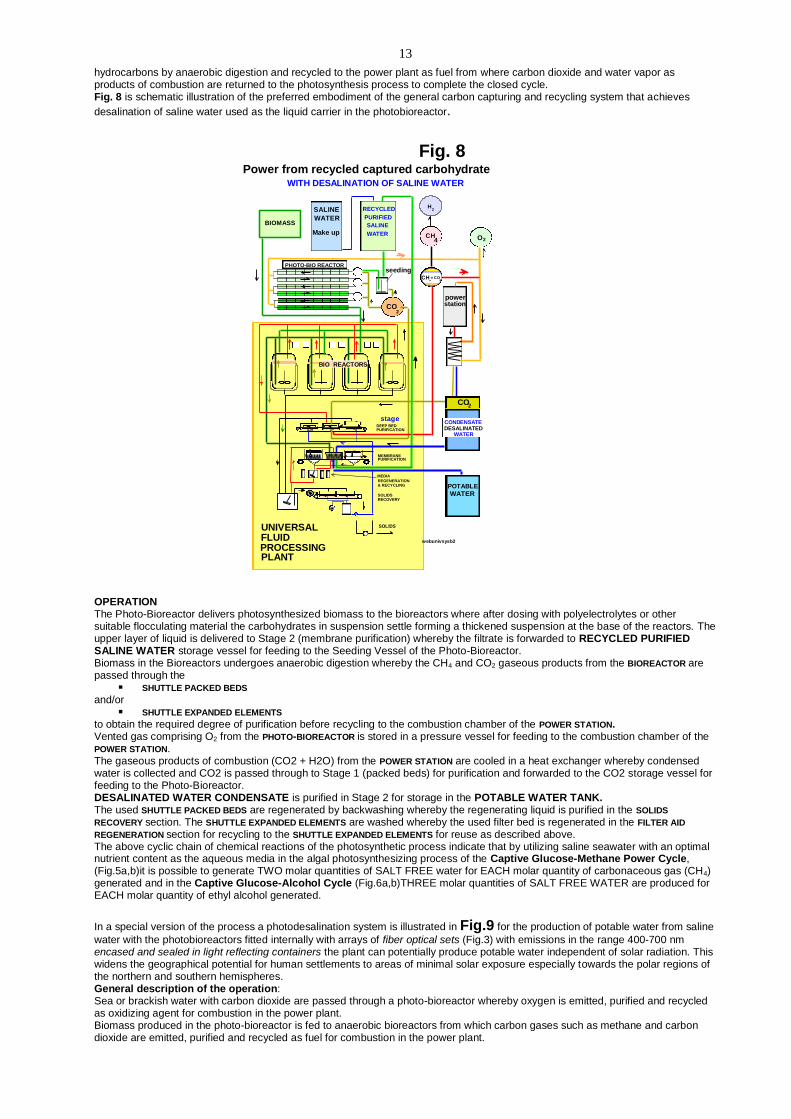
hydrocarbons by anaerobic digestion and recycled to the power plant as fuel from where carbon dioxide and water vapor as products of combustion are returned to the photosynthesis process to complete the closed cycle. Fig. 8 is schematic illustration of the preferred embodiment of the general carbon capturing and recycling system that achieves
desalination of saline water used as the liquid carrier in the photobioreactor.
OPERATION The Photo-Bioreactor delivers photosynthesized biomass to the bioreactors where after dosing with polyelectrolytes or other suitable flocculating material the carbohydrates in suspension settle forming a thickened suspension at the base of the reactors. The upper layer of liquid is delivered to Stage 2 (membrane purification) whereby the filtrate is forwarded to RECYCLED PURIFIED SALINE WATER storage vessel for feeding to the Seeding Vessel of the Photo-Bioreactor. Biomass in the Bioreactors undergoes anaerobic digestion whereby the CH4 and CO2 gaseous products from the BIOREACTOR are passed through the
SHUTTLE PACKED BEDS and/or
SHUTTLE EXPANDED ELEMENTS to obtain the required degree of purification before recycling to the combustion chamber of the POWER STATION. Vented gas comprising O2 from the PHOTO-BIOREACTOR is stored in a pressure vessel for feeding to the combustion chamber of the POWER STATION. The gaseous products of combustion (CO2 + H2O) from the POWER STATION are cooled in a heat exchanger whereby condensed water is collected and CO2 is passed through to Stage 1 (packed beds) for purification and forwarded to the CO2 storage vessel for feeding to the Photo-Bioreactor. DESALINATED WATER CONDENSATE is purified in Stage 2 for storage in the POTABLE WATER TANK. The used SHUTTLE PACKED BEDS are regenerated by backwashing whereby the regenerating liquid is purified in the SOLIDS
RECOVERY section. The SHUTTLE EXPANDED ELEMENTS are washed whereby the used filter bed is regenerated in the FILTER AID
REGENERATION section for recycling to the SHUTTLE EXPANDED ELEMENTS for reuse as described above. The above cyclic chain of chemical reactions of the photosynthetic process indicate that by utilizing saline seawater with an optimal nutrient content as the aqueous media in the algal photosynthesizing process of the Captive Glucose-Methane Power Cycle, (Fig.5a,b)it is possible to generate TWO molar quantities of SALT FREE water for EACH molar quantity of carbonaceous gas (CH4) generated and in the Captive Glucose-Alcohol Cycle (Fig.6a,b)THREE molar quantities of SALT FREE WATER are produced for EACH molar quantity of ethyl alcohol generated.
In a special version of the process a photodesalination system is illustrated in Fig.9 for the production of potable water from saline
water with the photobioreactors fitted internally with arrays of fiber optical sets (Fig.3) with emissions in the range 400-700 nm encased and sealed in light reflecting containers the plant can potentially produce potable water independent of solar radiation. This widens the geographical potential for human settlements to areas of minimal solar exposure especially towards the polar regions of the northern and southern hemispheres. General description of the operation: Sea or brackish water with carbon dioxide are passed through a photo-bioreactor whereby oxygen is emitted, purified and recycled as oxidizing agent for combustion in the power plant. Biomass produced in the photo-bioreactor is fed to anaerobic bioreactors from which carbon gases such as methane and carbon dioxide are emitted, purified and recycled as fuel for combustion in the power plant.
stageDEEP BEDPURIFICATION
H2
powerstation
O2
2
CO2
*
MEMBRANE
MEDIA
REGENERATION
SOLIDSRECOVERY
PURIFICATION
& RECYCLING
BIOMASS
CH4
SOLIDS
CO2
4CH CO+
2
BIO REACTORS
PHOTO-BIO REACTOR
SALINE
WATER
Make up
WITH DESALINATION OF SALINE WATER
WATER
UNIVERSAL
PROCESSINGPLANT
CONDENSATEDESALINATED
WATER
RECYCLED
PURIFIED
SALINE
WATER
POTABLE
WATER
FLUID
CO2
seeding
Power from recycled captured carbohydrate
webunivsysb2
Fig. 8

14
The electric energy generated in the power plant is transmitted to the photosynthesizing unit in which artificial lighting units are embedded to activate the photosynthesizing process in the absence of solar radiation input. The water vapor generated by the combustion process of the power plant is condensed in heat exchangers that preheat the emitted gases from photosynthesis and anaerobic digestion and fermentation fed as fuel to the power station. Thus totally closed systems for the production of potable water are available for application anywhere on the surface of the globe within the vicinity of sea or brackish water for use in the vicinity or piped elsewhere. The waters of the oceans of the earth, originally saline, were and still are the major sites of photosynthesizing processes and carbon storage. Marine nano-, micro- and macro-algae then and now are the main organisms participating in the conversion of CO2 in the atmosphere to carbohydrates. This proven sustainable mechanism can be exploited by mankind to take control of our own environment. Economics of photodesalination Preliminary calculations indicate that the production cost of potable water from saline water by photosynthesis undercuts the nearest competitive process of Reverse Osmosis by approximately 50% with the added advantage that there are no emissions of green house gases and there are no emissions of environmental damaging liquid effluents. State of the art vs Innovation of the invention: Photodesalination: Capital Amortization / Operating Cost: ca. £0.35/m
3
Reverse Osmosis: Capital Amort./ Energy / Operating Cost ca. £0.65/m3.
CLAIMS 18-19 18. A photosynthesizing system according to Claim 1 and Fig.9 for the production of desalinated (potable) water from sea and saline water that is potentially independent of solar energy input, whereby sea or brackish water with carbon dioxide are passed through a photo-bioreactor whereby oxygen is emitted, purified and recycled as oxidizing agent for combustion in power generation and biomass, produced in the photosynthesizing bioreactor, is fed to anaerobic bioreactors from which carbon gas is emitted, purified and recycled as fuel for combustion in the power plant where the electric energy generated in the power plant is transmitted to the photosynthesizing unit to energize embedded artificial lighting units including laser optical fiber sets emitting electromagnetic radiation within the range 400-700 nm to activate the photosynthesizing process in the absence of solar radiation input and whereby water vapor originally extracted from the saline water in photosynthesizing process is regenerated by the combustion process of the power plant where it is condensed, purified and stored as desalinated water. 19. Process according to Claim 1 and Fig.8 whereby solar generated photosynthesized biomass from PHOTO-BIOREACTORS using saline water as carrier, reactant and nutrient medium is fed with recycled biomass from diverse sources to BIOREACTORS to produce power and potable water.
photoSYN
FILTER
POWER
FILTER
TRANSMISSION
~
~
+-
sea
waterbrackish
/potablewater
bioreactors
condensersheat
e -
sea water
PHOTODESALINATION OF SEAWATER
PLANT
4CH+
2CO
4CH
+
2CO
+ 2CO
O2
+ 2CO
O2
H O2
H O2
CO2
CO2
exchangers
IN
OUT
gas
gas
Fig. 9
r&do408AAA

15
4. Production facilities of human habitats Global industry and communities should be actively planning for a switch from PETRO to PHOTO based technologies for all forms of production facilities. Fossil fuel deposits are dwindling and should be preserved for special use by future generations and not squandered for present global demands for energy generation and carbon-based industries. Fig 15 provides a simplified version of a future human habitat wholly based on solar energy including a comprehensive production facility entitled UNIVERSAL PROCESSING PLANT that can produce a wide range of petrochemicals from basic building blocks such as methane, alcohol, hydrogen and oxygen. The plant is fitted out with standard reactor vessels and distillation units that are suitable for a large range of bio/chemical production by the innovative fluid purification and solid’s recovery systems.
Horticulture, Agriculture and Farming in Human Settlements Recent international political activity points to the continuing trend of communities wanting to become independent of outside supplies of basic food and other commodities. Fulfilling this need will however for many of the regions of the planet remain wishful thinking unless new innovative infrastructure and methods of food production are realized. That many parts of the world are dependent on grain deliveries from for example America and Australia for their very survival is unacceptable in an age when serious plans are being hatched for the establishment of human settlements in outer space. Recent rapid increases in the global cost of primary food resources must pave the way in the search for more productive agricultural methods suitable for application anywhere on the planet. Traditional agriculture is failing in many regions of the earth due to adverse climatic conditions. With the rapid increase in world population dire predictions of mass starvation are becoming more and more credible. Leaving plans for human settlements in outer space aside, the priority on our planet should be to develop agricultural systems for human settlements that are selfsustainable and independent of the external environment and the vagaries of global weather patterns. This goal requires the realization of the important interconnected technology of the present disclosure: A schematic representation of an innovative system is illustrated in Fig.10 for contained agriculture with purification and captive recycling and reuse of circulated fluids including fertilizers, nutrients as well as carbon dioxide. The crops are completely sealed off from the external environment as well as the earth strata on which they rest which is covered and sealed by an impervious layer such as concrete. The plant root systems are embedded in a resistant aggregate with a suitable range of grain sizes to provide the necessary root support and access to fluid nutrients continuously fed to and distributed throughout the entire aggregate layer. The crops are sealed under removable translucent hinged covers. Conditioned purified carbon dioxide originating from the power generating facilities after purification is continually
Fig.15
PHOTOSYNTHESISENERGY
HORTI-PACKAGING
animalFARMING
MILK PRODUCTSAnimal Feed
PHOTO
HORTICULTUREPHOTO
MARKET
Insulated sealed housingwith air purification
CO2
O2 MEAT PACKAGING
SETTLEMENT
ARABLECROPS
photo-voltaicENERGY
GRAIN PRODUCTS
BUILDINGS
+-E-grid
PROCESSING
UNIVERSAL
PLANT
Anaerobic Digestion
Se wage
Treatment
Potable
Water
Power
Station
FUELS
BEVERAGES
FOOD
Pharmaceuticals
CHEMICALS
SUGARS
ALCOHOL
HYDROGEN
OXYGEN
sterile WATER / AIR
SALINE
WATER
H2
H O2
FU
EL
carbonaceous
converter matter
toBIOMASS
CH4
CH4
AIR
ZEROCARBONARIALXXXA
ALCOHOL
alcohol

16
circulated through and over the growing crops and maintained at a constant temperature and carbon dioxide and moisture concentration by conventional conditioning systems while bleeding off a controlled fraction of the circulating gas and replenishing with a high percentage concentration of carbon dioxide. The use of artificial lighting for photosynthesis is an option at all times. Automated harvesting equipment is one of the priorities. There is almost no limit to the variety of crops from tropical to temperate climatic types that can be grown with the system. For this reason individual habitats will cooperate with surrounding habitats each specializing in a range of crops and fruits whereby interregional commercial relationships will be encouraged. An important food commodity in the human habitats of the invention is from fish farming. Habitats in the vicinity of seawater are ideally situated to for carrying out extensive fish breeding and farming that can render such settlements independent of outside supplies of protein. The success of such systems depend on an integrated fluid purification process that can only be economically justified as part of a comprehensive scheme for selfsustainable human habitats dependent on photosynthetic power generation, potable water production and purified gas atmospheres. The maintenance of a high degree of sanitation and freedom from insects and extraneous microorganisms are for the systems a top priority. The strength of such a systems within photosynthesizing human habitations lies in the high degree of conservation of nutrients, carbon and water within the confines of the human community This can be best understood by consulting the simplified Fig.15 where the aim is to comprehensively capture and recycle all emissions and waste within the confines of settlements. Over half the earth’s land mass is unsuited for human habitation. The nearest available water is saline and unusable for conventional agricultural purposes. Much of this territory including North and South Africa, the Middle East, West and South America, southern Europe, Australia during daylight hours is almost continually bathed in sunshine. Sunlight, seawater and carbon dioxide is the concoction of nature that led to success. It was from this combination that life on earth evolved and thrived and by building on and boosting nature’s accomplishment mankind can assure its future survival and successful existence. Australia, the driest continent is continuing to suffer from intensifying drought conditions forcing inhabitants to flee the inland and a large part of the coastal areas. The depicted large coastline and inland areas show how sea (red) and saline artesian water (blue dots) could transform the situation. Selfsustainable habitats based on an inexhaustible provision of SUNLIGHT, SEA WATER and CARBON DIOXIDE can completely revolutionize the situation. The ringed areas on the map of the world could be transformed into a mosaic of oases completely independent of external supplies of essential raw materials. The Middle East depicted below completely surrounded by saline water including the Black and Caspian Seas could be transformed into the genuine Garden of Eden.
Solid’s Recovery State of the art solid’s recovery apparatus illustrated on the left hand column under the title “Filters for (cake) recovery” (Fig.11) depicts the parallel further evolutionary development of both the “nutsche” and the “filter press” progenitors. The complete range is immense and bewildering even for experienced engineers and is indicative of today’s cul de sac in that today’s users are often forced to return to the progenitor filter press to solve many pressing problematic fluid purification and solids recovery requirements.
ZEROCARBAGRI1
CO2
CO2+
2O
CROP
earth strata
CROP
DRAINAGE
RADIATION
imperviouslayer layer
PROCESSINGFLUID
PLANTCROP
AGGREGATE
CONTAINED HORTI- & AGRICULTUREFRONT ELEVATION
SIDE EVELATION
PLAN VIEW
CAPTIVE RECYCLING
impervious
earth strata
Fig. 10
17
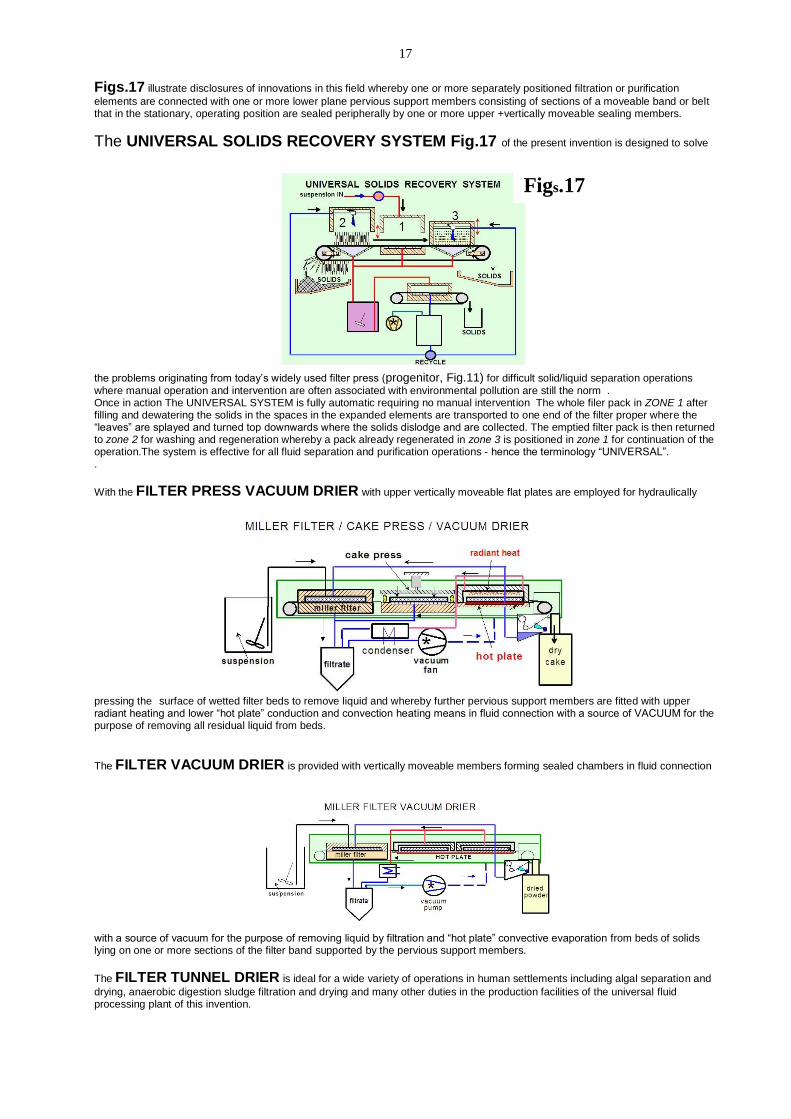
Figs.17 illustrate disclosures of innovations in this field whereby one or more separately positioned filtration or purification
elements are connected with one or more lower plane pervious support members consisting of sections of a moveable band or belt that in the stationary, operating position are sealed peripherally by one or more upper +vertically moveable sealing members.
The UNIVERSAL SOLIDS RECOVERY SYSTEM Fig.17 of the present invention is designed to solve
the problems originating from today’s widely used filter press (progenitor, Fig.11) for difficult solid/liquid separation operations
where manual operation and intervention are often associated with environmental pollution are still the norm . Once in action The UNIVERSAL SYSTEM is fully automatic requiring no manual intervention The whole filer pack in ZONE 1 after filling and dewatering the solids in the spaces in the expanded elements are transported to one end of the filter proper where the “leaves” are splayed and turned top downwards where the solids dislodge and are collected. The emptied filter pack is then returned to zone 2 for washing and regeneration whereby a pack already regenerated in zone 3 is positioned in zone 1 for continuation of the operation.The system is effective for all fluid separation and purification operations - hence the terminology “UNIVERSAL”. .
With the FILTER PRESS VACUUM DRIER with upper vertically moveable flat plates are employed for hydraulically pressing the surface of wetted filter beds to remove liquid and whereby further pervious support members are fitted with upper radiant heating and lower “hot plate” conduction and convection heating means in fluid connection with a source of VACUUM for the purpose of removing all residual liquid from beds.
The FILTER VACUUM DRIER is provided with vertically moveable members forming sealed chambers in fluid connection
with a source of vacuum for the purpose of removing liquid by filtration and “hot plate” convective evaporation from beds of solids lying on one or more sections of the filter band supported by the pervious support members.
The FILTER TUNNEL DRIER is ideal for a wide variety of operations in human settlements including algal separation and
drying, anaerobic digestion sludge filtration and drying and many other duties in the production facilities of the universal fluid processing plant of this invention.
Figs.17

18
Operation One or more separately positioned elements moveable with respect to one or more pervious support members forming sealed chambers whereby in a further sealed chamber heated gas is circulated above and below to dry deposited wet beds lying on stationary sections of a moveable pervious filter band. CLAIMS 20-27 20. Fluid purification apparatus and system according to Claim 13 and Figs. 17 wherein a plurality of purification members integral with sections of filter band can be transferred by the band to a plurality of separate pervious support members thus enabling simultaneous liquid purification and further distinctive operational procedures to be carried out with the purification members or the deposited solids thereon. 21. Fluid purification apparatus and system according to Claim 13 and Fig. 17 entitled FILTER / CAKE PRESS / VACUUM DRIER whereby one or more separately positioned elements moveable with respect to one or more pervious support members consisting of vertically moveable flat plates for pressing on the surface of filter beds comprising deposited solids material lying on sections of filter band and one or more pervious support members fitted with radiant heating elements above and below the pervious support members all for the purpose of removing residual liquid and drying said beds. 22. Fluid purification apparatus and system according to Claim 13 and Fig.17 entitled FILTER / VACUUM DRIER whereby one or more separately positioned elements moveable with respect to one or more pervious support members forming sealed chambers in fluid connection with a source of vacuum for the purpose of removing liquid by evaporation from the solids material lying on one or more sections of the filter band supported by the pervious support members. 23. Solids’ recovery apparatus and system according to Claim 13 and Fig.17 entitled UNIVERSAL SOLIDS RECOVERY STSTEM comprises one or more separately positioned vertically moveable sealing elements with respect o one or more solids’ recovery members integral with the sealed sections of filter band taking the form of shuttle extended filter surface elements whereby in operation the solids filling the voids of the expanded elements after dewatering are splayed on deflection rollers and turned top downwards whereby the solids are deposited and collected. 24. Fluid purification apparatus and system according to Claim 13 and Fig.17 entitled FILTER TUNNEL DRIER whereby one or more separately positioned elements are moveable with respect to one or more pervious support members forming sealed chambers whereby a further separately positioned sealing element consists of a chamber through which heated gas is circulated to dry deposited solids’ material laying on a stationary section or sections of moveable filter band supported by pervious support members. 25. Systems for contained agriculture according to Fig.10 and any one or combination of components disclosed in Claims 1-24 to purify and recycle drainage irrigation liquid and evolved gases. 26. Selfsustainable human habitats with cyclic captive processes according to Claims 1-25 and Fig.15 comprising a plurality of photosynthesizing units and recycling facilities for producing fuel for power stations, horticultural products, animal fodder and arable crops capable of sustaining human populations in cyclic closed systems with comprehensive processing and reuse of all waste-liquids, -gases and -solids all sealed off from the environment providing all essential energy and food requirements of the human habitat; whereby all purified fluids (water/air), beverages, sugar, food, chemicals, alcohol, hydrogen, fuel, photochemicals, oxygen, methane, carbon dioxide, etc. are produced in unique or identical universal fluid processing plants integrated in closed systems with power plants, photosynthesizing facilities, potable water production, water and wastewater treatment plants all interconnected and interdependent resulting in ZERO EMISSIONS into the environment . 27. Human settlements according to any one or more of Claims 1-26 and Figs.15,16 disclosing the provision of facilities and processes for the maintenance of selfsufficient human habitats in hitherto sparsely inhabited or empty regions of planet earth showing examples of potential sites for the establishment of such habitats.
Figs. 18a, llustrate a comparison of the space occupied by state fo the art and method of the present invention for providing
potable water from medium quality surface water for a population of 1 million. The ratio of the surface area taken up is approx.: ~ 10 / 1
State of the art vs Universal System of the invention
Fig. 18b
MILLER FILTER TUNNEL DRIER
Fig.18a
19
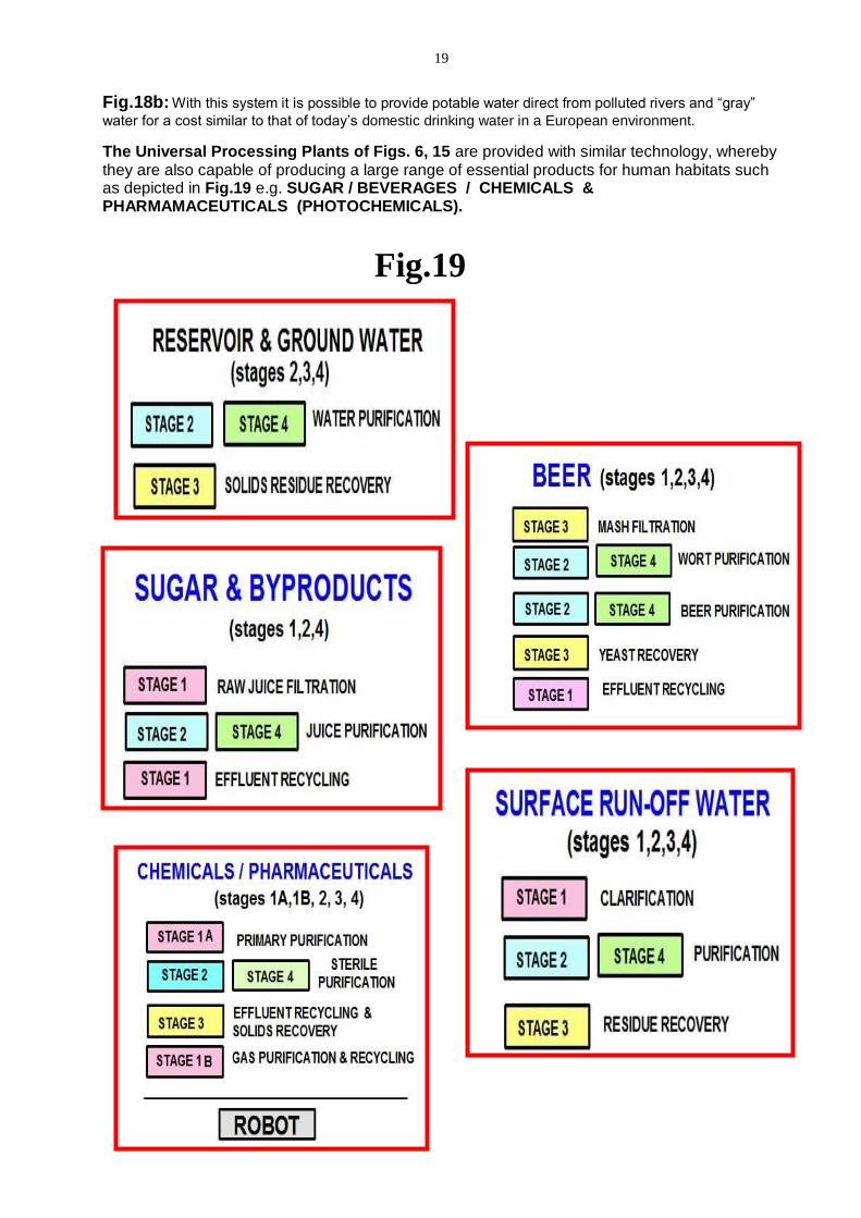
Fig.18b: With this system it is possible to provide potable water direct from polluted rivers and “gray”
water for a cost similar to that of today’s domestic drinking water in a European environment.
The Universal Processing Plants of Figs. 6, 15 are provided with similar technology, whereby they are also capable of producing a large range of essential products for human habitats such as depicted in Fig.19 e.g. SUGAR / BEVERAGES / CHEMICALS & PHARMAMACEUTICALS (PHOTOCHEMICALS).
Fig.19

20
ABSTRACT Systems of total capture and recycling of used organic and inorganic matter of the earth’s environment to enable the realization of selfsustainable human habitations in previously uninhabitable areas of the earth and thereby contribute to the elimination of environmental pollution. Disclosed is a combination of interconnected innovative technologies to enable the realization of self-sustainable communities largely independent of outside man-made energy and potable water combined with ZERO fluid emissions into the environment that point the way to a sustainable solution of the global warming and environmental pollution problems comprising large scale cyclic photosynthetic carbon capture and associated fluid purification systems with fluid recycling and solids’ recovery systems. Schematised illustrations provide the principles of the present invention, whereby carbon gases emitted from conventional power stations and other combustion processes are converted by photosynthesis to carbohydrates then hydrocarbons and recycled as fuel in captive closed systems thus completely eliminating emissions of green house gases to the atmosphere as well as providing the precondition for maintaining a high degree of sanitation of the process. Fluid purification systems are disclosed to enable the long-term recycling and reuse of the photosynthesising fluids involved in the power generation and all fluid streams generated and used within selfsustainable human habitats. abso8ipc


![Advances in Porous Organic Polymers for Efficient Water Capture · 2019-10-31 · Advances in Porous Organic Polymers for Efficient Water Capture Yearin [a]Byun+, ... Summary of textural](https://img.pdfslide.us/doc/110x75/5f49bd1f748e9e12703af3d1/advances-in-porous-organic-polymers-for-efficient-water-capture-2019-10-31-advances.jpg)