Embed Size (px)
Citation preview
Chapter 5
Systems of particles
So far, we have discussed only the application of Newton’s laws to particles, or to bodies in situationswhere they can be treated as particles — planets in orbit round the Sun, for example.
In this chapter, we apply Newton’s laws to systems of interacting particles, which could beas simple as two particles moving in each other’s gravitational field (for example, a planet movinground the Sun that it is large enough for it not be a good approximation to regard the Sun as fixed)or as complicated as a solid body comprising many billions of atoms or a multi-component systemsuch as a rocket.
Luckily, we do not have to analyse the motion of the individual particles: there are usefulgeneral results that give nearly all the information we need. Examples are conservation of momen-tum, suitably defined, and ‘F = Ma’, where M is the total mass, a the acceleration of the centreof mass and F the sum (suitably defined) of the external forces.
The situation is analogous to the theory of perfect gases. We could in principle, but not inpractice, calculate the individual motions of the 1023 atoms in a mole of the gas, but we don’t haveto, because almost everything we need can be obtained from relations between thermodynamicsvariables pressure, volume, temperature and entropy.
5.1 Equations of motion
We consider a system of n particles. The ith particle has mass mi, position vector ri1 relative to
some inertial frame and momentum pi, where2
pi = miri.
Two sorts of force act on the ith particle: an external force due to some force field independent ofour system (gravity, for example) and n − 1 internal forces (e.g. gravitational or electromagnetic)due to the other particles in the system. The internal forces hold the system together, possibly butnot necessarily, rigidly. We denote the external force on the ith particle by Fe
i , and the force onthe ith particle due to the jth particle by Fij . Note that
Fij = −Fji (5.1)
by Newton’s third law.Newton’s second law holds for each individual particle:
dpi
dt= Fe
i +∑
j 6=i
Fij . (5.2)
and these are the equations of motion of the system. However, they are not much use in this form,at least if n is large, and in the following sections we explore ways of obtaining the essence of themotion without having to integrate n second-order differential equations.
1Careful! The subscript labels particles not components of vectors; you really need to underline your vectors soas not to get in a muddle.
2If we were considering relativistic dynamics rather than Newtonian dynamics (see section 6.7), then we shoulduse
pi = miγiri,
where mi is rest mass and γi =ą1− ri · ri/c2
ć− 12 .
1
2 CHAPTER 5. SYSTEMS OF PARTICLES
5.1.1 Momentum of the system
We start by defining the total momentum of the system, which will help us understand how thatsystem as a whole responds to external forces.
So far, we have not encountered the concept of momentum except for a single particle. Doesit make sense to ask what is the total momentum of two particles? If so, how should it be defined?Since we are free to define the momentum of the system as we wish, we will obviously choose adefinition that results in nice equations; maybe something like Newton’s second law.
We define the total momentum P of the system of particles, in the obvious way,3 as the sumof the individual momenta:
P =n∑
i=1
pi (5.3)
We wish to investigate the way the total momentum varies (aiming for something like Newton’ssecond law), so it is a good plan to differentiate it:
dPdt
=d
dt
n∑
i=1
pi (by definition of P)
=n∑
i=1
dpi
dt
=n∑
i=1
Fe
i +∑
j 6=i
Fij
(using Newton’s second law (5.2))
= Fe +n∑
i=1
∑
j 6=i
Fij (we define Fe as sum of external forces)
= Fe +n∑
i=1
∑
j 6=i
12 (Fij − Fji) (by Newton’s third law (5.1))
= Fe (because the double sum is symmetric in i and j)
ThusdPdt
= Fe (5.4)
This is a pleasing result, exactly analogous to Newton’s second law for a single particle, providedthe total force is suitably defined (as the sum of the external forces). In particular, if Fe = 0,
dPdt
= 0
so if the external forces on the individual particles sum to zero, the total momentum is conserved.If the external force is gravitational, so that
Fei = mig
and
Fe =n∑
i=1
mig = Mg,
where M is the total mass of the system, then
dPdt
= Mg . (5.5)
In this case, the rate of change of total momentum is governed by the total mass rather than bythe individual masses.
3This might seem a bit random. How do we know what the definition of total momentum should be; or indeed ifany such definition would prove useful? In chapter 2, I mentioned (in a footnote) that the underlying symmetry ofthe theory gives rise, by Noether’s theorem to conserved quantities. The same is true for a system of particles. Thetranslation symmetry ri → ri + a (same a for each i) implies that there is a conserved momentum corresponding tothe sum of the individual momenta.
5.1. EQUATIONS OF MOTION 3
We can go further. We define the centre of mass, R, of the system as a weighted average:
MR =n∑
i=1
miri. (5.6)
The origin of the name ‘centre of mass’ comes from the action of a uniform gravitational fieldg on the system. The total moment of the force about the origin (which is an arbitrary fixed point)is
n∑
i=0
(ri × (mig)) = R× (Mg)
so the moment of the gravitational force can be thought of as acting at the point R; one could placea pivot at this point and the system would balance (since the moment of the force about the pivotwould be zero). system
Differentiating equation (5.6) gives
MdRdt
=d
dt
n∑
i=1
miri, =n∑
i=1
miri = P (5.7)
and
Md2Rdt2
= Fe. (5.8)
Thus the acceleration of the centre of mass is determined directly by the total external force andthe centre of mass of the system moves exactly as a single particle of mass M in a force field Fe.
If the total external force is zero, the centre of mass moves with constant speed. If the externalforce is gravitational, then
Md2Rdt2
=n∑
i=1
(mig) = Mg
5.1.2 Angular momentum
Having obtained a generalisation of Newton’s second law to systems of particles, we can now applythe same technique to angular momentum, hoping to generalise the single particle ‘rate of changeof angular momentum equals torque’ result.
To save writing, we consider angular momentum about the origin; having obtained the result,the transformation r → r− a will yield the corresponding result for the angular momentum aboutany fixed point a.
We define the total angular momentum of the system H about a fixed origin to be the sum ofthe angular momenta of the individual particles:
H =n∑
i=1
ri × pi. (5.9)
Now we differentiate:
dHdt
=n∑
i=1
dri
dt× pi +
n∑
i=1
ri × dpi
dt(5.10)
=n∑
i=1
ri × (miri) +n∑
i=1
ri ×Fe
i +∑
j 6=i
Fij
(using Newton’s second law (5.2))
= 0 + G +n∑
i=1
∑
j 6=i
ri × Fij (5.11)
where G is the total external torque defined by G =n∑
i=1
ri × Fei .
If, as is the case for a system of gravitating masses, the internal forces are central, so that
Fij ‖ (ri − rj) (5.12)
4 CHAPTER 5. SYSTEMS OF PARTICLES
we can simplify further. For convenience, we define
F11 = F22 = · · · = Fnn = 0.
Thenn∑
i=1
∑
j 6=i
ri × Fij =n∑
i=1
n∑
j=1
ri × Fij
=n∑
j=1
n∑
i=1
rj × Fji (relabelling the suffices)
= −n∑
j=1
n∑
i=1
rj × Fij (Fij is antisymmetric)
= −n∑
i=1
n∑
j=1
rj × Fij (exchanging order of sumations)
= 12
n∑
i=1
n∑
j=1
(ri − rj)× Fij (Fij is antisymmetric)
= 0 (since Fij is central (5.12))
To obtain the penultimate equation, we added the right hand sides of the first line and the fourthline.
Thus for central internal forces, we have the result
dHdt
= G, (5.13)
just as in the case of a single particle; in particular, if G = 0, the total angular momentum of thesystem is conserved.
If the external force is a uniform gravitational field, we obtain another very important result:
G =n∑
i=1
ri × Fe
=n∑
i=1
ri × (mig)
=
(n∑
i=1
miri
)× g
= MR× g
= R× (Mg). (5.14)
Thus the total external torque acts as if all the mass of the system were concentrated at the centreof mass.
5.1.3 Energy
How should we define the kinetic energy of the system? As before, we assume that it is additiveand accordingly define the total kinetic energy of the system, T , by
T =n∑
i=0
12miri · ri. (5.15)
Rather less clear is how to define the potential energy of the system. We assume that theinternal force between any two particles is central (acts along the line ri − rj) and depends onlyon the distance between the two particles, as in the gravitational case. In this case, the force canbe derived from a potential, and we assume that the potential function is the same for all pairs ofparticles. We denote the potential at ri due to a particle at rj is φ(rij), so that the force experiencedby a particle at ri due to the particle at rj is
Fij = −∇iφ(rij) (5.16)
5.1. EQUATIONS OF MOTION 5
Here, the subscript i on the ∇ means that the derivative is with respect to the components of ri
(it does not denote the ith component, and in what follows summation convention does not apply)and
rij = |ri − rj)| = rji.
Note that
∇iφ(rij) =dφ(rij)
drij∇irij = −∇jφ(rij).
The second equality follows from the chain rule. where ...4
5.1.4 The centre of mass frame
Sometimes, it is helpful to use the centre of mass as the origin of coordinates. This can lead tosimplifications in the equations and a greater level of understanding, but we have to be careful: thecentre of mass may be accelerating (in fact, it must if Fe 6= 0), so the new axes may not be inertial.
The main results of this section show that the motion of the system can be very convenientlydecomposed as the motion of the particles with respect to the centre of mass and the independentmotion of the centre of mass. The motion of the centre of mass can be regarded as that of a singleparticle of mass M , the total mass of the system.
We denote the position of the ith particle with respect to the centre of mass R by yi, so that
ri = R + yi. (5.17)
Thusn∑
i=1
miyi =n∑
i=1
miR−n∑
i=1
miri = MR−MR = 0 (5.18)
and similarlyn∑
i=1
miyi = 0 (5.19)
This last equation says that the momentum in the centre of mass frame, PM is zero:
PM ≡n∑
i=1
miyi = 0 (5.20)
and, for this reason, the centre of mass frame is sometimes called the centre of momentum frame.Note that equation (5.20) does not imply that the total external force on the system vanishes inthe centre of mass frame; it just emphasises the point that Newton’s second law, in the form (5.4)holds generally only in inertial frames.
We obtain yet another very useful result by considering the angular momentum with respectto the centre of mass HM . We can relate HM to H as follows:
HM ≡n∑
i=1
miyi × yi
=n∑
i=1
mi(ri −R)× (ri − R)
=n∑
i=1
miri × ri −n∑
i=1
miR× ri −n∑
i=1
miri × R +n∑
i=1
miR× R
= H−R×n∑
i=1
miri −(
n∑
i=1
miri
)× R + MR× R
= H−R× (MR)−MR× R + MR× R (using 5.6 twice)
= H−MR× R.
In words, this says that the angular momentum H about the origin is equal to the angular momen-tum HM about the centre of mass plus the angular momentum about the origin of a particle oftotal mass M situated at the centre of mass.
4Note to self: this is a bit complicated. Is it really necessary? It’s OK just to do it for the two-particle case inthe next section.
6 CHAPTER 5. SYSTEMS OF PARTICLES
Now we consider the rate of change of angular momentum about the centre of mass. At firstsight, it seems that we can simply change the origin in equation (5.13) to R, obtaining
dHM
dt= GM , (5.21)
where
HM =n∑
i=1
yi × (miyi)
and
GM =n∑
i=1
yi × Fei .
But one cannot simply change the origin to R because the derivation of equation (5.13) requiredthe use of Newton’s second law, which in turn assumed that the frame was inertial, whereas thecentre of mass accelerates if the total external force is non-zero (see equation (5.8)). Nevertheless,very pleasingly, it turns out that the result (5.21) is correct, as can easily be seen. We have
dHM
dt=
n∑
i=1
miyi × yi
=n∑
i=1
miyi ×(ri − R
)
=n∑
i=1
miyi × ri −(
n∑
i=1
miyi
)× R
=n∑
i=1
yi × (miri) (using (5.18))
=n∑
i=1
yi ×Fe
i +∑
j 6=i
Fij
. (using (5.2))
In the case when the internal forces are central, so that Fij ‖ (rj − ri) = (yj − yi), we can repeatexactly the calculations that lead to equation (5.13) to obtain the required result
dHM
dt=
n∑
i=1
yi × Fei ≡ GM . (5.22)
In the external force is a uniform gravitational field,
GM =n∑
i=1
yi × Fei =
n∑
i=1
yi × (mig) =
(n∑
i=1
miyi
)× g = 0
by (5.18), so the system rotates freely about its centre of mass.The kinetic energy of the system comes out nicely in the centre of mass frame. Using (5.17),
we have
T =n∑
i=0
12mi
(yi + R
)·(yi + R
)
=n∑
i=0
12miyi · yi + 1
2
n∑
i=1
miR · R + R ·n∑
i=1
miyi
=n∑
i=0
12miyi · yi + 1
2MR · R (5.23)
where, for the last equality, we have used (5.19).In words, equation (5.23) says that the total kinetic energy can be thought of as the total
kinetic energy in the centre of mass frame plus the kinetic energy of the total mass positioned atthe centre of mass. This result holds in all circumstances: we have not assumed that the centre ofmass frame is inertial.
5.1. EQUATIONS OF MOTION 7
5.1.5 Example: drum majorette’s baton
A drum majorette’s baton is a short heavy stick which the drum majorette throws spinning intothe air and, if all goes well, catches again.
We model the baton as a light rod of length ` with masses m1 and m2 attached firmly to theends. What happens when the stick is thrown up into the air?5
Let y1 and y2 be the position vectors of the two masses with respect to the centre of mass.Then
m1y1 + m2y2 = 0
(see equation (5.6)).Setting |yi| = yi, we have y1 + y2 = ` and (from the above equation)
m1y1 = m2y2 (5.24)
The external force on the system is the uniform gravitational field g. The internal force is thestress or tension in the light rod. This force is central: it acts in the direction of the vector joiningthe two particles.
Let R be the position of the centre of mass. From equation (5.7) we know that
MR = Fe = m1g + m2g = Mg
so the centre of mass moves exactly as if it were a single particle of mass M in a gravitational field.The angular momentum HM about the centre of mass satisfies equation (5.21)
HM = GM .
The gravitational torque GM about the centre of mass is
y1 × (m1g) + y2 × (m2g) = (m1y1 + m2y2)× g = 0 (5.25)
by definition of the centre of mass (5.6). Thus the angular momentum about the centre of mass ofthe baton is constant.
Since the rod is rigid, the two masses are rotating about the centre of mass with the sameangular velocity ω. The velocity of the mass mi is therefore ω × yi and
HM = m1y1 × (ω × y1) + m2y2 × (ω × y2). (5.26)
The axis of rotation is perpendicular to the rod; since the rod is thin and the masses are particlesthey cannot rotate about an axis parallel to the rod. Expanding the vector products in equation(5.26) and using ω · yi = 0 shows that
HM = (m1y21 + m2y
22)ω.
The centre of mass is fixed in the rod, so y21 and y2
2 are constant. The external torque about thecentre of mass being zero therefore implies that ω is constant, so θ is constant in the motion, whereθ is the angle the baton makes with the vertical, and |θ| = |ω|.
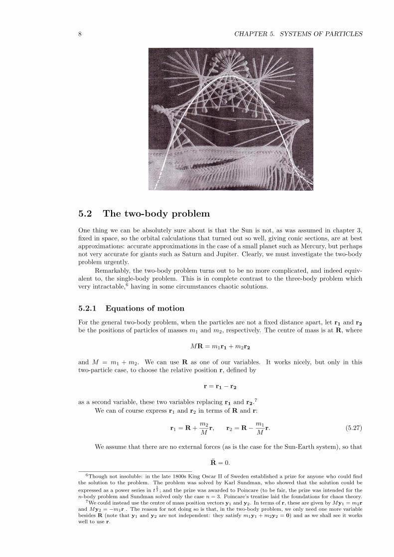
The time lapse photograph below shows this nicely: the centre of mass moves on a parabolaand the angle of the rod changes by the same amount between each exposure.
5Note to self: could do with a picture.
8 CHAPTER 5. SYSTEMS OF PARTICLES
5.2 The two-body problem
One thing we can be absolutely sure about is that the Sun is not, as was assumed in chapter 3,fixed in space, so the orbital calculations that turned out so well, giving conic sections, are at bestapproximations: accurate approximations in the case of a small planet such as Mercury, but perhapsnot very accurate for giants such as Saturn and Jupiter. Clearly, we must investigate the two-bodyproblem urgently.
Remarkably, the two-body problem turns out to be no more complicated, and indeed equiv-alent to, the single-body problem. This is in complete contrast to the three-body problem whichvery intractable,6 having in some circumstances chaotic solutions.
5.2.1 Equations of motion
For the general two-body problem, when the particles are not a fixed distance apart, let r1 and r2be the positions of particles of masses m1 and m2, respectively. The centre of mass is at R, where
MR = m1r1 + m2r2
and M = m1 + m2. We can use R as one of our variables. It works nicely, but only in thistwo-particle case, to choose the relative position r, defined by
r = r1 − r2
as a second variable, these two variables replacing r1 and r2.7
We can of course express r1 and r2 in terms of R and r:
r1 = R +m2
Mr, r2 = R− m1
Mr. (5.27)
We assume that there are no external forces (as is the case for the Sun-Earth system), so that
R = 0.
6Though not insoluble: in the late 1800s King Oscar II of Sweden established a prize for anyone who could findthe solution to the problem. The problem was solved by Karl Sundman, who showed that the solution could be
expressed as a power series in t13 ; and the prize was awarded to Poincare (to be fair, the prize was intended for the
n-body problem and Sundman solved only the case n = 3. Poincare’s treatise laid the foundations for chaos theory.7We could instead use the centre of mass position vectors y1 and y2. In terms of r, these are given by My1 = m2r
and My2 = −m1r . The reason for not doing so is that, in the two-body problem, we only need one more variablebesides R (note that y1 and y2 are not independent: they satisfy m1y1 + m2y2 = 0) and as we shall see it workswell to use r.
5.2. THE TWO-BODY PROBLEM 9
The motion of the relative position vector is governed by
r ≡ r1 − r2 (by definition)
=1
m1F12 − 1
m2F21 (applying Newton’s second law)
=m1 + m2
m1m2F12 (5.28)
which we can write asµr = F12 (5.29)
where µ, the reduced mass, is defined by
µ =m1m2
m1 + m2. (5.30)
In the gravitational case, the equation of motion (5.29) becomes
µr = −Gm1m2
r3r i.e. r = −GM
r3r (5.31)
which is exactly the same as the equation of motion for a single particle of mass M . As we showedin section 3.5, the motion is planar and can be written in the form
r =`
e cos θ ± 1.
From (5.27), we see that
r1 −R =m2
Mr
so the motion of each particle relative to the centre of mass is directly determined by the motion ofr. That means the motion of the individual particles consists of a constant drift due to the motionof the centre of mass, plus elliptical, hyperbolic or parabolic motion with the centre of mass as thefocus.
If F12 is a central force, i.e. it is directed along r and depends in magnitude only on |r|, wecan write it in the form8
F(r) = −∇φ(r)
for some potential function φ(r) (see section 2.1). In this case, we can define the total energy E ofsystem by
E = T + φ(r)
where the total kinetic energy T is given by
T = 12m1r1 · r1 + 1
2m2r2 · r2
= 12m1
(R +
m2
Mr)·(R +
m2
Mr)
+ 12m2
(R− m1
Mr)·(R− m1
Mr)
= 12MR · R + 1
2µr · r
where the reduced mass µ is given by definition (5.30).We can now easily show that the total energy E is a constant of the motion:
dE
dt= MR · R + µr · r +
dφ
dt
= r · F + ∇φ · r (R = 0 (no external forces) and (5.29))= 0 (definition of φ)
8For all the previous work, we could just as well have used variables R and (say) y1 (the position vector of oneof the particles with respect to the centre of mass). For the potential, it is much more convenient to use R and r asabove.
10 CHAPTER 5. SYSTEMS OF PARTICLES
5.2.2 Tides
This is another extended footnote: interesting, I hope, but not part of the course.We consider the Earth-Moon system as consisting of a pair of gravitationally interacting point
masses.Recall that for a two-body system, we write
r = r1 − r2
so thatr = r1 − r2 =
1m1
F12 − 1m2
F21 =m2 + m1
m1m2F12
where F12 is the force on particle 1 due to particle 2. In the gravitational case, this becomes
r =(
m2 + m1
m1m2
)(−Gm1m2
r3r)
= −GM
r3r.
where M = m1 +m2. This is exactly the same equation as for a particle moving in the gravitationalfield of a fixed mass M , so we can wheel out all our standard orbit calculations.
As it happens, the Earth-Moon distance is roughly constant, so we can treat the orbit as acircle:
rθ2 =GM
r2
where M = Me + Mm is the combined mass of the Earth and Moon. The period of the orbit, 2π/θfor a circular orbit, is therefore (cf Kepler’s third law)
2π
√r3
GM. (∗)
We can evaluate GM using GM/R2e = g, where Re is the radius of the Earth and g is the acceleration
due to gravity. Taking Re ≈ 6.4× 10⁶ metres, g ≈ 10ms−2, the Earth-Moon distance r ≈ 4× 10⁸mand 2π ≈ 6 gives a period of 2.4× 10⁶ seconds, which is surprisingly close (given our rather cavalierapproximations) to 28 days.
Nowr1 = R +
m1
m1 + m2r
where R is the position vector of the centre of mass, which we assume to be fixed in space (thoughin fact it rotates round the Sun), and there is a corresponding result for r2. This means that boththe Earth and the Moon orbit their common centre of mass. Since the mass of the moon is about1% of the mass of the Earth, the centre of the Earth is about 4000 kilometres from the commoncentre of gravity which means that the joint centre of mass lies inside the Earth.
From this picture, we can understand the reason that there are two tides a day. At the centreof the Earth, in the rotating frame of the Earth-Moon, the centrifugal force and the gravitationalattraction of the moon balance. At the point on the surface of the Earth nearest the Moon, theMoon’s pull exceeds the centrifugal force9. At the point on the Earth’s surface furthest from theMoon, the centrifugal force exceeds the Moon’s gravitational pull. Thus a particle of seawaterexperiences an excess force towards the Moon on one side of the Earth and away from the Moonon the other side of the Earth. The sea will therefore bulge on both sides.
We can do the calculations: we will prove that the force acting on a particle of seawater atthe point on the Earth’s surface nearest the moon is the same as at the point on the Earth’s surfacefurthest from the moon, which shows not only that there are high tides at the same time on oppositesides of the Earth, but also that the heights of the high tides are the same.
9It is best in this explanation to think of the Earth and Moon rotating round a common centre of mass somewherein space between the two bodies. In fact, as noted above, the centre of mass lies within the Earth. Thus at the pointon the Earth’s surface nearest to the Moon, the centrifugal force and the Moon’s pull are in the same direction.
5.3. VARIABLE MASS PROBLEMS 11
R
ra
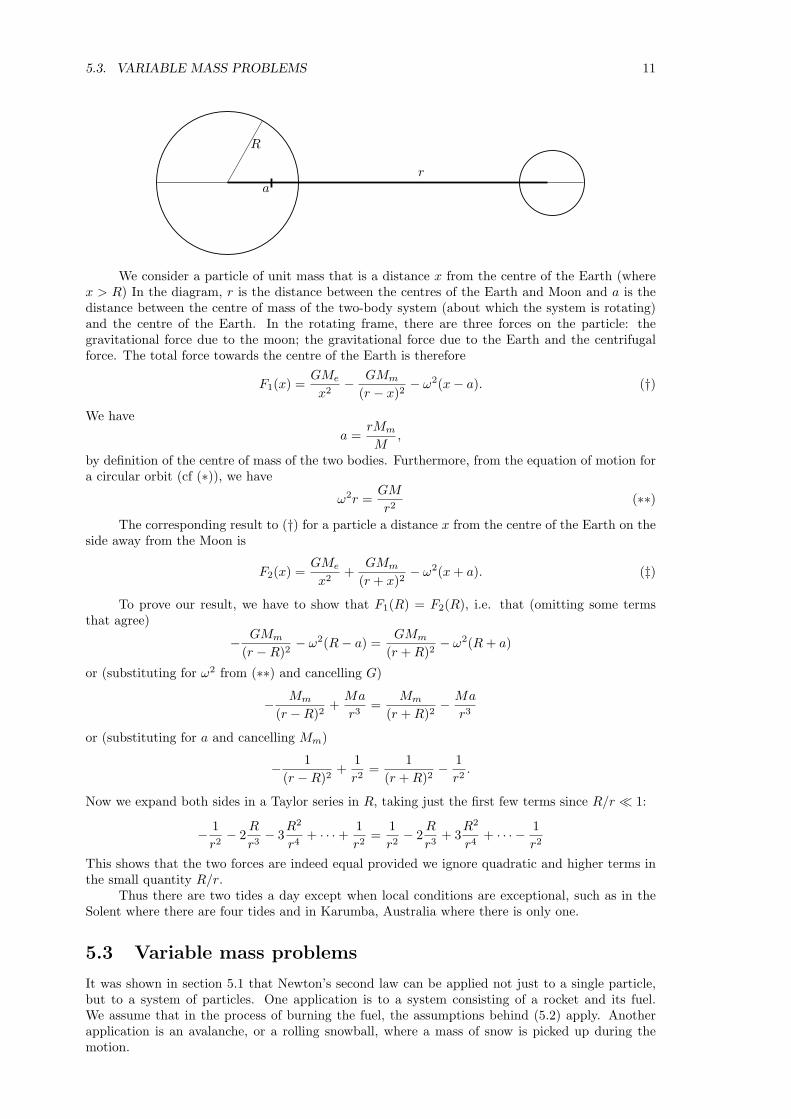
We consider a particle of unit mass that is a distance x from the centre of the Earth (wherex > R) In the diagram, r is the distance between the centres of the Earth and Moon and a is thedistance between the centre of mass of the two-body system (about which the system is rotating)and the centre of the Earth. In the rotating frame, there are three forces on the particle: thegravitational force due to the moon; the gravitational force due to the Earth and the centrifugalforce. The total force towards the centre of the Earth is therefore
F1(x) =GMe
x2− GMm
(r − x)2− ω2(x− a). (†)
We havea =
rMm
M,
by definition of the centre of mass of the two bodies. Furthermore, from the equation of motion fora circular orbit (cf (∗)), we have
ω2r =GM
r2(∗∗)
The corresponding result to (†) for a particle a distance x from the centre of the Earth on theside away from the Moon is
F2(x) =GMe
x2+
GMm
(r + x)2− ω2(x + a). (‡)
To prove our result, we have to show that F1(R) = F2(R), i.e. that (omitting some termsthat agree)
− GMm
(r −R)2− ω2(R− a) =
GMm
(r + R)2− ω2(R + a)
or (substituting for ω2 from (∗∗) and cancelling G)
− Mm
(r −R)2+
Ma
r3=
Mm
(r + R)2− Ma
r3
or (substituting for a and cancelling Mm)
− 1(r −R)2
+1r2
=1
(r + R)2− 1
r2.
Now we expand both sides in a Taylor series in R, taking just the first few terms since R/r ¿ 1:
− 1r2− 2
R
r3− 3
R2
r4+ · · ·+ 1
r2=
1r2− 2
R
r3+ 3
R2
r4+ · · · − 1
r2
This shows that the two forces are indeed equal provided we ignore quadratic and higher terms inthe small quantity R/r.
Thus there are two tides a day except when local conditions are exceptional, such as in theSolent where there are four tides and in Karumba, Australia where there is only one.
5.3 Variable mass problems
It was shown in section 5.1 that Newton’s second law can be applied not just to a single particle,but to a system of particles. One application is to a system consisting of a rocket and its fuel.We assume that in the process of burning the fuel, the assumptions behind (5.2) apply. Anotherapplication is an avalanche, or a rolling snowball, where a mass of snow is picked up during themotion.
12 CHAPTER 5. SYSTEMS OF PARTICLES
5.4 Rockets
5.4.1 The rocket equation
We consider a rocket which has mass m(t) at time t, where m(t) includes both the fixed mass of therocket without fuel and the mass of the fuel on board at time t. For simplicity, we assume that therocket is moving along the positive x-axis. Its velocity v(t) and we take v(t) > 0 (this is helpful butnot necessary). It emits exhaust backwards at a velocity −u (where u > 0) relative to the rocket.The rocket is subject to an external force which could, for example, be gravity or friction.
We use the equationdPdt
= Fe
where P is the total momentum of the system and Fe is the total external force (see section 5.1.1).This holds in any inertial frame. It only assumes that the internal forces (in this case, the explosiveburning of the rocket fuel) obey Newton’s third law.
We therefore calculate the rate of change of momentum between times t and t+ δt; we do notneed to worry about all the exhaust gasses that were emitted before this time.
The momentum of the system at time t is
m(t)v(t)
and the momentum at time t + δt, when the mass of the rocket has decreased to m(t + δt) and amass m(t)−m(t + δt) of fuel has been converted to exhaust gases and ejected at speed v − u, is
m(t + δt)v(t + δt) + [m(t)−m(t + δt)](v − u).
The rate of change of momentum is therefore given by
dP
dt= lim
δt→0
m(t + δt)v(t + δt) + [m(t)−m(t + δt)](v − u)−m(t)v(t)δt
= limδt→0
m(t + δt)v(t + δt)−m(t)v(t)δt
+ limδt→0
[m(t)−m(t + δt)](v − u)δt
=d(mv)
dt− dm
dt(v − u)
= mdv
dt+ u
dm
dt
som
dv
dt+ u
dm
dt= F (5.32)
which is the rocket equation. Here, F is the external force on the rocket; the external force on theejected fuel will tend to zero when we take the limit δt → 0 since then δm → 0.
If F = 0, we can write the rocket equation as
dv
dt+ u
1m
dm
dt= 0
which can be integrated in the case when u does not vary with time:
v(t)− v(0) = u ln(
m(0)m(t)
). (5.33)
This is called the Tsiolkovski equation.10
In the casedm
dt= −α
10The equation was apparently (though this seems very surprising) first written down by Konstantin Tsiolkovski asrecently as 1903. Tsiolkovski was also responsible for the idea of the space elevator, which consists of a cable (carbonnanotubes) attached to a geostationary satellite. The cable extends higher than the satellite and has a mass on theend; this provides tension, since on this portion of the cable the centrifugal force outwards exceeds the gravitationalforce inwards. On the lower portion of the cable, the reverse is true, and the elevator has to have an engine topower it up the cable. As the elevator goes up the cable, its tangential velocity increases; total angular momentumis conserved, so the climber’s increased angular momentum is compensated by a decrease of angular velocity of theEarth. There will a horizontal coriolis force, dragging the cable, due to the vertical velocity of the elevator in therotating frame. I bet it never happens.
5.4. ROCKETS 13
where α is a positive constant, we can write
m(t) = m(0)− αt
and substituting this into the Tsiolkovski equation (5.33) gives an equation that can be easilyintegrated to give x(t).
The rocket equation (5.32) can easily be understood (in fact, can be much more easily derived)working in the instantaneous rest frame of the rocket at fixed time t. The instantaneous rest framemoves at a constant velocity which is the velocity of the rocket at one instant only. It is an inertialframe. In contrast, the centre of mass frame of the rocket is thei generally non-inertial frame thatmoves with the centre of mass of the rocket; in this frame the momentum of the rocket is alwayszero.
We work in the frame that has the same velocity as the rocket at time t. In this frame, themomentum at time t is zero:
P (t) = 0.
At time t+δt, when the speed of the rocket has increased by δv, the mass of the rocket has increasedby δm (actually, a decrease of −δm where δm < 0) and a mass −δm of fuel has been ejected, so
P (t + δt) = (m + δm)δv + (−δm)(−u).
Ignoring second order quantities, this leads immediately to
F = limδt→0
(m
δv
δt+ u
δm
δt
).
Of course, this is the same calculation as the previous calculation, except that we have replacedany velocity V with V − v.
The rocket equation can be obtained even more directly as follows. Since it doesn’t matterwhat happens to the exhaust gases after they are ejected, we assume that they move unimpeded,i.e. they experience no force and move with constant velocity. The total momentum of the exhaustgases at time t is then ∫
(v − u)dm
with appropriate limits. Thus
P (t) = mv +∫
(v − u)dm
or
P (t) = mv +∫ t
0
(v − u)dm
dtdt.
Differentiating this with respect to t and using Newton’s second law in the form (5.4) gives therocket equation without further work.
5.4.2 Example: rocket with linear drag
A rocket burns fuel at a constant mass rate α and expels it at constant relative speed u. Itexperiences linear air resistance. The initial mass of the rocket is m0, of which a fraction 1 − β(0 < β < 1) is fuel, and it is initially at rest in deep space. What is the speed of the rocket whenall the fuel has been burnt?
Let v be the velocity and m the mass at time t. We do not need to find the time, so we willeliminate t from the rocket equation using the chain rule:
d
dt=
dm
dt
d
dm= −α
d
dm.
The rocket equation (5.32) with resistive force kv is
mv + um = −kv
14 CHAPTER 5. SYSTEMS OF PARTICLES
where k is the coefficient of air resistance; so
−αmdv
dm− αu = −kv
=⇒ dv
dm=
kv − αu
αm(5.34)
=⇒∫
dv
kv − αu=
∫dm
αm
=⇒ k−1 ln[(αu− kv)/αu] = α−1 ln(m/m0) ,
where we have used the initial condition v = 0 when m = m0 in the last equation. Note that weexpect the velocity to increase when the mass decreases, so equation (5.34) shows that kv−αu > 0.
Tidying up a bit:
1k
ln(
1− kv
αu
)=
1α
lnm
m0
=⇒ 1− kv
αu=
(m
m0
)k/α
=⇒ v =αu
k
{1−
(m
m0
)k/α}.
When all the fuel is burnt, m = βm0 so vfinal = (αu/k)(1− βk/α).We see that there is a theoretical maximum speed of αu/k, achievable only if the rocket is
entirely made up of fuel.
5.4.3 Example: avalanches
The model is a compact mass of snow sliding down a slope, picking up the snow immediately infront of it as it goes. It is like rolling a snow ball to make a snowman, except that (i) avalanchesslide rather than roll and (ii) avalanches take up the width of the slope (more cylindrical thenspherical).11
Let m be the mass of snow in the avalanche at time t, and let v be the speed at which it issliding down the slope. We can use the rocket equation (5.32) directly, with u = v since the snowon the slope is at rest:
mdv
dt+ v
dm
dt= mg sinα,
where α is the inclination of the slope. Note that this is exactly the equation we would have obtainedusing Newton’s second law directly:
d(mv)dt
= force.
If we assume that the depth of snow is a constant h on the slope and that the avalanche picksit all up, then
m = ρhx,
where ρ is the density of the snow and x is the distance moved by the avalanche at time t. Thus
d(ρhxv)dt
= ρhxg sinα.
Cancelling the constant factors and using the chain rule gives
vd(xv)dx
= xg sin α
which can be easily solved. For example, we could write it as
(xv)d(xv)dx
= x2g sin α
11Note to self: can the two-snowplough problem be adapted? In that problem, the speed of the ploughs wasinversely proportional to the depth of snow, but if the ploughs worked at constant power, the result might be similar.
5.5. MOMENT OF INERTIA 15
giving12 (xv)2 = 1
3x3g sin α
i.e.v2 = 2
3xg sinα (5.35)
and hence, if we want it, x as a function of time. We can obtain a more interesting result bydifferentiating equation (5.35) respect to time t:
2vdv
dt= 2
3xvg sin α
which shows (after cancelling v) that the acceleration of an avalanche in this very crude model, is13 of the acceleration of a skier heading down the same slope (ignoring resistance). That suggeststhat skiers should be able to out-run avalanches, especially if they have a head start.12
5.5 Moment of inertia
5.5.1 Definition
For a rotating system, with all particles rotating about the same axis with the same angular velocity(such as a rigid body), it is convenient to use angular acceleration rather than linear accelerationin the equations of motion. These equations, using angular acceleration, can be made to resemblethe equations using linear acceleration by replacing mass by moment of inertia, defined as follows.
We start by considering a single particle rotating with angular velocity ω about an axisthrough the origin. The kinetic energy T is given by
T = 12mr · r = 1
2m(ω × r) · (ω × r)
= 12mω2(k× r) · (k× r) (setting ω = ωk, where k · k = 1)
= 12ma2ω2
where, in spherical polar coordinates,
a = |k× r| = r sin θ
so a is the distance from the particle from the axis of rotation. By analogy with
T = 12mv2
we writeT = 1
2Iω2 (5.36)
where I, defined by,I = ma2 ≡ m(k× r) · (k× r) (5.37)
is the moment of inertia of single particle of mass m about an axis through the origin which is adistance a from the particle.
For a rigid body consisting of n particles (all necessarily rotating about the same axis at thesame angular speed), we have for the total kinetic energy
T =n∑
i=1
12mi(aiω)2 = 1
2ω2n∑
i=1
mia2i ,
where mi is the mass of the ith particle and ai is the distance from the ith particle from the axis.Accordingly, we define the moment of inertia of the body by
I =n∑
i=1
mia2i ≡
∑mi(k× ri) · (k× ri) (5.38)
so that, again,T = 1
2Iω2.
12Don’t rely on it: I doubt if a real avalanche bears any resemblance to this model.
16 CHAPTER 5. SYSTEMS OF PARTICLES
For a solid body13, we replace the summation by an integral, and the individual masses byρ(r)dV :
I =∫
body
(r sin θ)2ρdV
where r and θ are spherical polar coordinates and the polar direction of the coordinates is chosento be along the axis of rotation, so that the distance of the element of mass at r from the axis isr sin θ.
5.5.2 Examples
(i) Uniform rod, axis perpendicular to rod.Let ` be the length of the rod and ρ be the line density (mass per unit length). Then the
moment of inertial about an axis perpendicular to the rod passing through one end is
I =∫ `
0
ρx2dx = 13ρ`3 = 1
3M`2,
where M is the mass of the rod.
(ii) Circular hoop, axis through centre of hoop perpendicular to the plane of the hoopWe consider a system of particles of total mass M all situated on a circular hoop. The moment
of inertia of this system about an axis through the centre of the hoop and perpendicular to theplane of the hoop is just (since the moment of the inertia of the system is the sum of the momentsof inertia of the individual particles)
I = Ma2,
where a is the radius of the hoop.
(iii) Uniform circular disc, axis through centre perpendicular to discWe consider a uniform disc of mass M with radius a and surface density (mass per unit area)
ρ. In this case we have to do an integral. We can be high-tech and do the surface integral (usingplane polar coordinates) ∫ a
0
∫ 2π
0
ρr2rdθdr = 14ρ(2πa4) = 1
2Ma2;
this method would work also for a non-uniform disc, for which ρ depended on r and θ, though theanswer would be different. Or we can be low-tech, and break down the disc into hoops add up theindividual moments of inertia of the hoops.
(iv) Uniform disc, axis through point on circumference perpendicular to discWe consider the same disc as above, with the axis of rotation passing through the point r = a,
θ = 0; call this point a. This time, the distance of the point r with coordinates (r, θ) from the axisa is given by
distance from axis =√
(r− a) · (r− a)
=√
r2 + a2 − 2r · a
=√
r2 + a2 − 2ar cos θ.
so
I =∫ a
0
∫ 2π
0
ρ(r2 + a2 − 2ar cos θ)rdθdr = 32Ma2.
(v) Uniform disc, axis through centre in plane of discWe choose plane polar coordinates so that θ = 0 corresponds to the direction of the axis of
rotation. The point with coordinates (r, θ) is a distance |r sin θ| from the axis, so
I =∫ a
0
∫ 2π
0
ρ(r sin θ)2rdθdr = 14Ma2.
(vi) Uniform sphere, axis through centre
13By a solid body, we mean a body made of a continuous medium rather than individual particles
5.5. MOMENT OF INERTIA 17
We choose spherical polar coordinates with the axis (θ = 0) pointing in the direction of theaxis of rotation. Then
I =∫ a
0
∫ π
0
∫ 2π
0
ρ(r sin θ)2r2 sin θdφdθdr = 815πρa5 = 2
5Ma2.
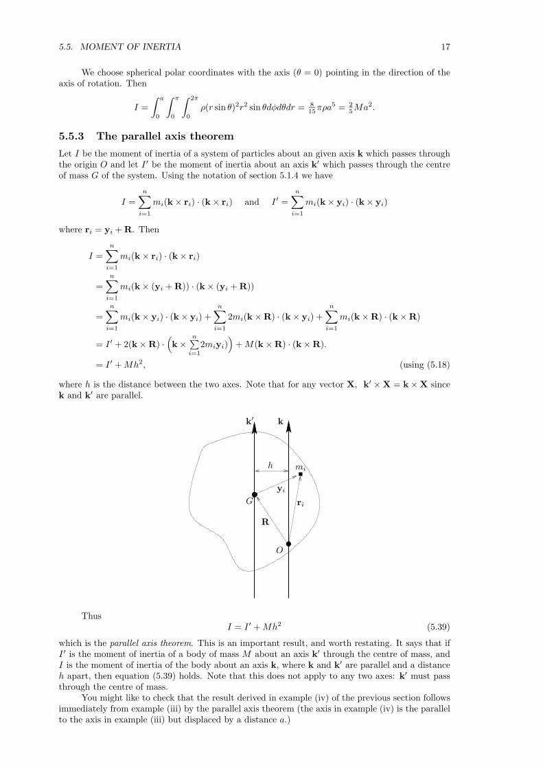
5.5.3 The parallel axis theorem
Let I be the moment of inertia of a system of particles about an given axis k which passes throughthe origin O and let I ′ be the moment of inertia about an axis k′ which passes through the centreof mass G of the system. Using the notation of section 5.1.4 we have
I =n∑
i=1
mi(k× ri) · (k× ri) and I ′ =n∑
i=1
mi(k× yi) · (k× yi)
where ri = yi + R. Then
I =n∑
i=1
mi(k× ri) · (k× ri)
=n∑
i=1
mi(k× (yi + R)) · (k× (yi + R))
=n∑
i=1
mi(k× yi) · (k× yi) +n∑
i=1
2mi(k×R) · (k× yi) +n∑
i=1
mi(k×R) · (k×R)
= I ′ + 2(k×R) ·(k×
n∑i=1
2miyi))
+ M(k×R) · (k×R).
= I ′ + Mh2, (using (5.18)
where h is the distance between the two axes. Note that for any vector X, k′ ×X = k×X sincek and k′ are parallel.
h
G
O
yi
mi
R
ri
k′ k
ThusI = I ′ + Mh2 (5.39)
which is the parallel axis theorem. This is an important result, and worth restating. It says that ifI ′ is the moment of inertia of a body of mass M about an axis k′ through the centre of mass, andI is the moment of inertia of the body about an axis k, where k and k′ are parallel and a distanceh apart, then equation (5.39) holds. Note that this does not apply to any two axes: k′ must passthrough the centre of mass.
You might like to check that the result derived in example (iv) of the previous section followsimmediately from example (iii) by the parallel axis theorem (the axis in example (iv) is the parallelto the axis in example (iii) but displaced by a distance a.)
18 CHAPTER 5. SYSTEMS OF PARTICLES
5.5.4 Angular momentum
For a single particle rotating with angular speed ω about an axis k passing through the origin, theangular momentum H about the origin is given by
H = r× (mr)= mr× (ω × r) (5.40)= mωr× (k× r). (5.41)
The component of H in the direction of the axis of rotation is given by
H · k = mωr× (k× r) · k= mω(r× k) · (r× k) (using the cyclic property of scalar triple products)
= Iω ≡ ma2ω (5.42)
where a = r sin θ, which is the distance of the particle from the axis, in agreement with the formulaeused in section 3 for the angular momentum of a particle moving in a plane (‘mh = mr2θ’).
If the axis of rotation k is fixed, we can write
ω = ωk and ω = ωk
in which case we can differentiate equation (5.42) to obtain
G · k = Iω
where I is the moment of inertia of about the axis k.This equation, derived for a single particle, applies also to a rigid system of particles rotating
about a fixed axis since we can sum the moments of inertia of the individual particles on the lefthand side and sum the torques on the individual particles on the right hand side (provided theinternal forces are central — see section 5.1.2).
5.6 The inertia tensor
In the above calculations of moments of inertia of a disc, we considered two cases when the axis isthrough the centre of the disc: axis perpendicular to the plane of the disc and axis in the plane ofthe disc. It would be useful to be able to express the results of these two calculations as a singleentity. And it would be even more useful if this entity could be used, without further calculation,to provide also the moment of inertia about any other axis. By good fortune, such an entity exists:the inertia tensor.14
We could define the inertia tensor directly, but the same indirect approach as we used before,via the kinetic energy, is helpful. We consider a particle of mass m rotating with angular speed ωabout a fixed vector k that passes through the origin. The angular velocity ω is given by
ω = ωk.
The velocity of the particle is ω × r and the kinetic energy is given by
T = 12m(ω × r) · (ω × r)
= 12mω2(k× r) · (k× r)
= 12mω2
((k · k)(r · r)− (k · r)2)
= 12mω2 ((r · r)δij − xixj) kikj (5.43)
This last expression (5.43) has three parts to it: the angular speed, the axis of rotation and
12m ((r · r)δij − xixj) ≡ Iij . (5.44)
These three parts are independent: we can choose, at will, an angular speed, and axis of rotationand the matrix represented by the components (5.44), plug them into (5.43) and out will come thekinetic energy.
14If you don’t know yet what a tensor is, don’t worry: you will soon and anyway for present purposes you can justreplace the word ‘tensor’ with the word ‘matrix’ and no harm will be done.
5.6. THE INERTIA TENSOR 19
The part of the kinetic energy that refers only to the system of particles (and not to theangular velocity) is the matrix (5.44), which is called the inertia tensor of the system about theorigin r = 0. It tells us how the body responds to rotation about an arbitrary axis. That Iij arethe components of a (symmetric) tensor can be seen by applying the quotient rule to the definition
T = 12mω2Iijkikj
since T/mω2 is a scalar for any vector k.If the expression (5.44) looks complicated, one has only to write out the individual components
to see what it means. For example,
I11 = m((x2 + y2 + z2)δ11 − x2
)= m(y2 + z2) (5.45)
andI12 = −mxy.
Note thatI11 = Iiknink
where n is the vector (1, 0, 0). Also, we see from equation (5.45) that I11 is the moment of inertiaof the particle about n (because (y2 + z2)
12 is the distance from the particle to the n axis). Thus
the quantityIiknink
is the moment of inertia of the particle about an axis in the direction of n. This holds independentlyof the coordinate axes used15 and so is true for any vector n.
For a rigid system of particles, the moment of inertia is just the sum of the moments of inertiaof the individual particles. For a rigid body, the sums become integrals, so for example
I11 =∫
body
(y2 + z2)ρdV.
5.6.1 The parallel axis theorem again
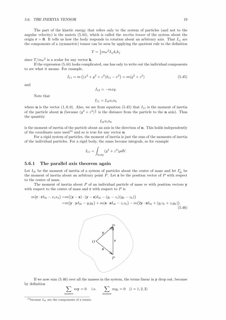
Let Iik be the moment of inertia of a system of particles about the centre of mass and let I ′ik bethe moment of inertia about an arbitrary point P . Let z be the position vector of P with respectto the centre of mass.
The moment of inertia about P of an individual particle of mass m with position vectors ywith respect to the centre of mass and r with respect to P is
m(r · rδik − xixk
)=m
((y − z) · (y − z)δik − (yi − zi)(yk − zk)
)
=m(y · yδik − yiyk
)+ m(z · zδik − zizk
)−m(2y · zδik + (yizk + ziyk)
).
(5.46)
y
rO
z
P
m
If we now sum (5.46) over all the masses in the system, the terms linear in y drop out, becauseby definition ∑
masses
my = 0 i.e.∑
masses
myi = 0 (i = 1, 2, 3)
15because Iik are the components of a tensor.
20 CHAPTER 5. SYSTEMS OF PARTICLES
ThusI ′ik = Iik + M(z · zδik − zizk
)
where M is the total mass of the system. This equation shows how to the inertia tensor about thecentre of mass of a body to the inertia tensor about another point fixed in the body.
Note that if we choose axes such that z = (h, 0, 0) or (0, h, 0), we find that
I ′33 = I33 + Mh2
which is the parallel axis theorem. This is an important result, and worth restating. It says that ifI is the moment of inertia of a body of mass M about an axis k through the centre of mass, and I ′
is the moment of inertia of the body about an axis k′, where k and k′ are parallel and a distanceh apart, then
I ′ = I + Mh2.
Note that this does not apply to any two axes: k must pass through the centre of mass.
5.7 Motion of a rigid body
5.7.1 Velocity
We consider a body consisting of n particles at fixed distances from each other. The mass of theith particle is mi and it has position vector ri with respect to a given origin fixed in space. Thecentre of mass of the particles is at R and the total mass is M where
MR =n∑
i=0
miri.
Let yi be the position vector of the ith particle with respect to the centre of mass, so that
ri = R + yi (5.47)
andri = R + yi (5.48)
Since the system is rigid, the distance from the centre of mass to each particle is fixed,which means that the only motion possible relative to the centre of mass is a rotation. By Euler’stheorem16, there is at each time an angular velocity vector ω (the same ω for each yi) such that
yi = ω × yi,
so that (5.48) becomesri = R + ω × yi (5.49)
or, using (5.47),ri = R + ω × (ri −R). (5.50)
We have not used the fact that yi is the position vector of the ith particle with respectspecifically to the centre of mass so we could equally well have written
ri = Q + ω′ × (ri −Q) (5.51)
where Q is the position vector of a point Q fixed in the body, and ω′ is the appropriate angularvelocity about Q. The question is: how are ω′ and ω related? And the answer is at first sightsurprising.
If we take ri = Q in equation (5.50) we obtain
Q = R + ω × (Q−R). (5.52)
Subtracting equation (5.52) from equation (5.50) gives
ri = Q + ω × (ri −Q) (5.53)
and comparing this with equation equation (5.51), which holds for any arbitrary position vector ri,we infer that
ω′ = ω (5.54)
so, rather remarkably, the angular velocity about any point of a rigid body is the same.A simple example shows that this not only makes sense, but is also a powerful tool for
calculating the speeds of points (or particles) on rigid bodies.16See section 4.2 for an off-syllabus discussion of Euler’s theorem
5.7. MOTION OF A RIGID BODY 21
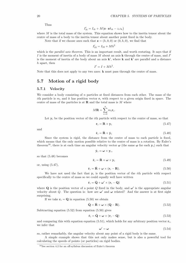
5.7.2 Example: angular velocity of rolling hoop
The figure shows a hoop of radius a rolling, without slipping, on a table. The point A is the point onthe hoop which is the instantaneous point of contact with the table. This point is instantaneouslyat rest, because of the no-slip condition.
The angular speed of the point P with respect to the centre of the hoop is θ so that the speedof P with respect to the centre is aθ. The speed of the centre itself is aθ. When θ = 0 the velocityof the with respect to the centre and the velocity of the centre are parallel so the velocity of the Pwhen θ = 0 is 2aθ.
It looks as if the angular speed about the fixed point A on the table might be 12 θ, but a
moment’s reflection shows that this must be wrong: when θ = 0 this would give the speed of P as2a(1
2 θ) instead of 2aθ. However, if the angular speed of P about A were θ (as we know it must befrom the calculation (5.54)), we obtain the correct speed.
The reason that the angular velocity of P about A is not 12 θ is that 1
2θ is the angle betweenAP and the diameter, and the diameter itself is rotating.
P
12θ
θ
A
a
Now we see the power of the result (5.54). To calculate the speed of P , to find the kineticenergy of a particle at P for example, all we need is
speed = AP × θ = (2a cos 12θ)θ.
To work out this result using Cartesian axes, or using (5.49) would have taken very considerablylonger.17
5.7.3 Kinetic Energy
For a simple motion, such as a ball rolling down an inclined plane, it is often easiest to use theconstancy of the total energy of the body to find the motion. We can calculate the kinetic energyTi of the ith particle using the expression (5.23), which becomes
Ti = 12miR · R + 1
2mi(ω × yi) · (ω × yi)
= 12miR · R + 1
2ω2
Summing over all particles givesT = 1
2MR · R + 12Iω2, (5.55)
where I is the moment of inertia of the whole system about the axis through it centre of mass.
5.7.4 Angular momentum
For a single particle rotating with angular speed ω about an axis k passing through the origin, theangular momentum H about the origin is given by
H = r× (mr)= mr× (ω × r) (5.56)= mωr× (k× r). (5.57)
17In cartesians, r = (aθ + a sin θ, a + a sin θ), which describes a cycloid. Thus v = (1 + cos θ,− sin θ)aθ), etc.
22 CHAPTER 5. SYSTEMS OF PARTICLES
The component of H in the direction of the axis of rotation is given by
H · k = mωr× (k× r) · k= mω(r× k) · (r× k) (using the cyclic property of scalar triple products)
= ma2ω (5.58)
where a = r sin θ, which is the distance of the particle from the axis, in agreement with the formulaeused in section 3 for the angular momentum of a particle moving in a plane (‘mh = mr2θ’). Thus
H · k = Iω. (5.59)
We can generalise this result using the inertia tensor. In suffix notation, equation (5.56)becomes
Hi = m (r× (ω × r))i
= m ((r · r)ω − (r · ω)r)i
= m ((r · r)δij − xixj)ωj
= Iijωj (5.60)
This is the generalisation of H = ma2ω, which we can retrieve by dotting both sides of equation(5.60) with ki:
Hiki = Iijωjki = ωIijkikj = ωI, (5.61)
where I here is the angular momentum about the axis k.If we apply H = G to (5.60), we obtain
Gi =d(Iijωj)
dt. (5.62)
This is as far as we can go, in general: differentiating the inertia tensor takes us into rather dangerousterritory.18
However, if the axis of rotation k is fixed, we can write
ω = ωk and ω = ωk
in which case we can differentiate equation (5.61) to obtain
G · k = Iω
where I is the moment of inertia of about the axis k.This equation, derived for a single particle, applies also to a rigid system of particles rotating
about a fixed axis since we can sum the moments of inertia of the individual particles on the lefthand side and sum the torques on the individual particles on the right hand side (provided theinternal forces are central — see section 5.1.2).
5.7.5 Uniform gravitation forces
We consider the effect of a uniform gravitational force acting on a rigid body. The (external) forceon each particle of the body is given by
Fei = mig
so that the total external force Fe has a simple form:
Fe ≡n∑
i=1
Fei = Mg.
Thus the position vector R of the centre of mass satisfies
MR = Mg18With respect to axes fixed in the body, which is how the inertia tensor would normally by calculated, the
components of the inertia tensor (Iij) would be constant (because the particles of the body are fixed relative to oneanother). However, these axes would move with the body, so the derivative would have to take into account rotationand acceleration of the body: the corresponding equations are named after Euler.
5.7. MOTION OF A RIGID BODY 23
so the centre of mass of the body moves along the trajectory of a single particle in the gravitationalfield.
The total torque about an arbitrary fixed point, which we take to be the origin r = 0, is givenby
G =n∑
i=1
ri × (mig) = MR× g (5.63)
so again the effect of the gravitational field on the body is the same as that a single particle of massM situated at its centre of mass:
dHdt
= MR× g,
where R is the position vector of the centre of mass with respect to the origin. In particular, if wechoose the origin to be at the centre of mass, so that R = 0, we see that the total torque about thecentre of mass is zero19:
dHM
dt= 0. (5.64)
If the body is rotating about a fixed axis k, we have
Iω = M(R× g) · k. (5.65)
We define the gravitational potential energy of the body to be the sum of the potential energiesof the individual particles:
φ = −n∑
i=1
mig · ri = −Mg ·R (5.66)
(Recall that in the usual axes, g = (0, 0,−g), so the minus sign in this expression cancels with theminus sign in the above equation to give the usual ‘+mgz’ expression for potential energy.)
From equation (5.66) we see that the gravitational potential of a rigid body is the same asthat of a single particle of mass M at the centre of mass.
Now we define the total energy E of the body by
E = T + φ
where T is the sum of the kinetic energies of the particles and φ is the sum of the gravitationalpotential energies of the particles. We can easily differentiate this to show that it is constant usingequations (5.64), (5.55) and (5.66).
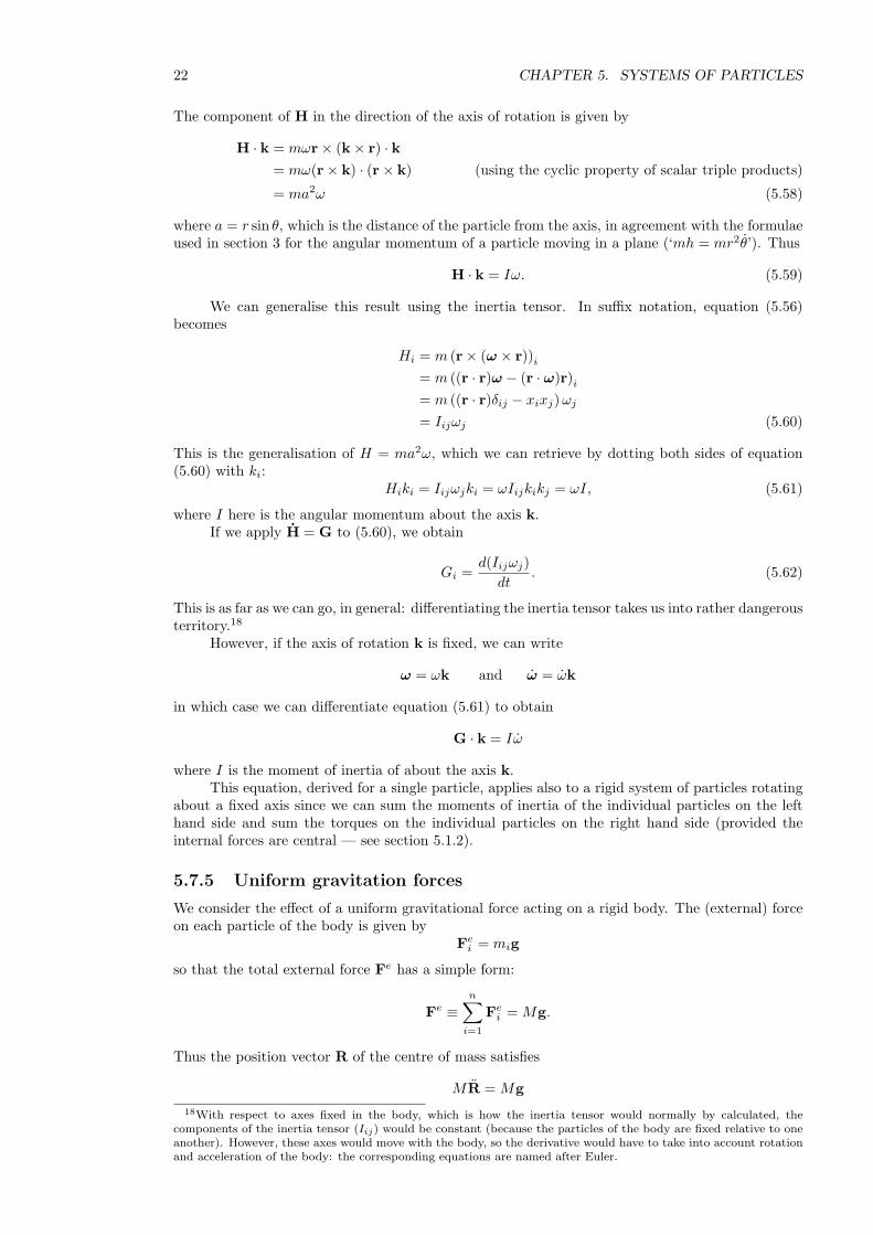
5.7.6 Example: motion of a swinging rod
A pendulum consists of a thin rod of mass m suspended from one end in such a way that it canswing in one vertical plane. Let I be the angular momentum of the rod about a horizontal axisperpendicular to the rod passing through its pivoted end. Let d be the distance between the centreof mass and the pivoted end of the rod.
19Recall thatdHM
dt= GM ,
(see equation (5.21)), even though the centre of mass is not fixed and might even be accelerating.
24 CHAPTER 5. SYSTEMS OF PARTICLES
mg
dθ
The kinetic energy of the swinging rod is
12Iθ2.
We could have obtained this a different way, using the expression (5.23) for the kinetic energy of abody:
T = ‘KE of centre of mass’ + ‘KE relative to centre of mass’
= 12m(dθ)2 + 1
2IM θ2,
where IM is the moment of inertia of the rod about the centre of mass. These two expressions agreeprovided
I = IM + md2
which holds by virtue of the parallel axis theorem.The potential energy of the rod relative the point of suspension is
−mgd cos θ
because, by (5.66), for a rigid body in a gravitational field, the potential energy is that of a particleof mass m situated at the centre of mass.
Thus the total energy E is given by
E = 12Iθ2 −mgd cos θ (†)
from which we obtain, by differentiating with respect to time t and cancelling an overall factor ofθ, the equation of motion
Iθ = −mgd sin θ.
This is equivalent to a simple pendulum of length I/md and the period of small oscillationsis 2π
√I/mgd.
We could equally well have obtained the equation of motion by taking moments about thepoint of suspension, using torque = moment of inertia × angular acceleration:
−mg × d sin θ = Iθ ,
since, by (5.65) the total torque is the same as for a particle of mass m situated at the centre ofmass.
If we needed to integrate this, it would probably be best to start instead with the energyconservation equation (†), which is already a first integral of the equation of motion. A furtherintegration gives an elliptic integral.
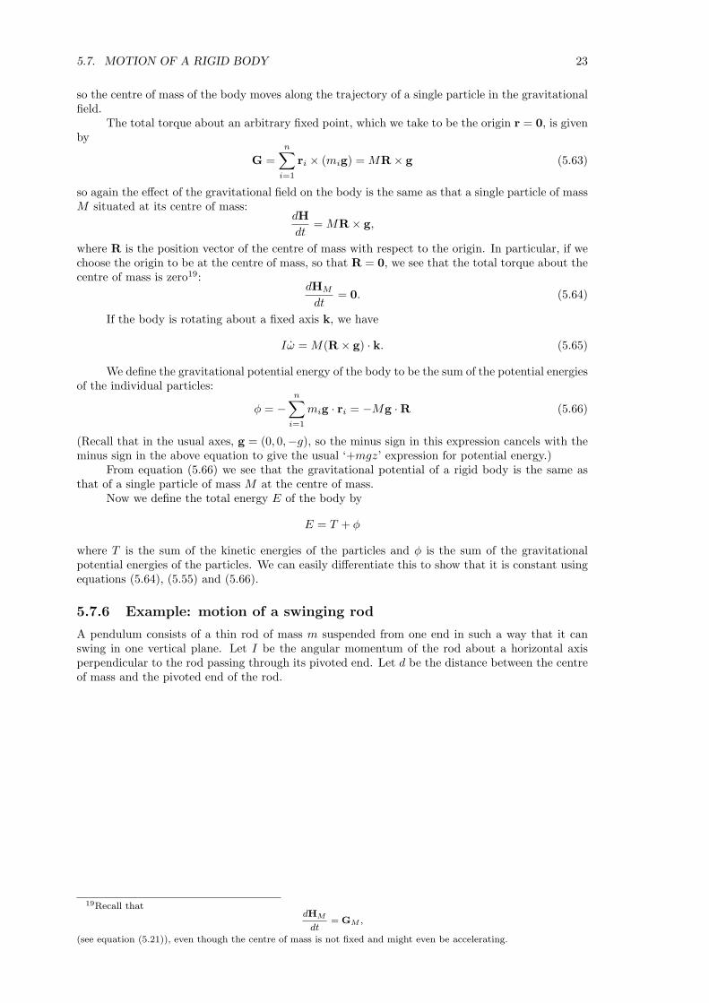
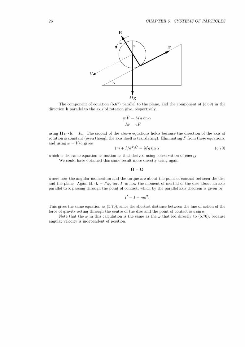
5.7.7 Example: rolling disc
A disc of mass M and radius a rolls without slipping down a line of greatest slope of an inclinedplane of angle α. The plane of the disc is vertical. The moment of inertial of the disc about andaxis through its centre perpendicular to the plane of the disc is I.
The motion of the disc consists of the linear motion of the centre of mass, which moves withspeed V down the plane, and rotation about the centre of mass with angular speed ω, as shown.The angular velocity vector sticks out of the paper (use the righ-handed corkscrew rule).
5.7. MOTION OF A RIGID BODY 25
V
α
ωa
The point on the circumference of the disc that is instantaneously in contact with the planeis instantaneously at rest, because of the no-slip condition. This means that V and ω are relatedby
V − aω = 0 .
This comes from V+ω×y = 0, were y is the position vector of the instantaneous point of contactwith respect to the centre of the disc. Taking instead the instantaneous point of contact as theorigin, this equation says that the velocity the centre of mass is due to the rotation with angularvelocity of ω about the point of contact.
Using conservation of energyThe kinetic energy (using the result that the total KE is ‘KE of centre of mass’ plus ‘KE
relative to centre of mass’) of the disc is
12MV 2 + 1
2Iω2 = 12MV 2 + 1
2 I(V/a)2 = 12 (I/a2 + M)V 2.
Let x be the distance down the plane that the disc has rolled at time t, so that x = V . Thenconserving energy20 gives
12 (I/a2 + M)x2 −Mgx sin α = constant.
We have used the result (5.66) that the gravitational potential energy of the body (in a uniformgravitational field) is the same as that of a single particle of mass M at the centre of mass. Curiously,the quickest way to integrate this is to differentiate it and cancel a factor of x, leaving a linearequation:
(I/a2 + M)x = Mg sin α
which can then be integrated twice. We see that the acceleration of a rolling disc is less, by a factorof 1 + I/Ma2, than that of the same disc sliding without rolling down the same plane.
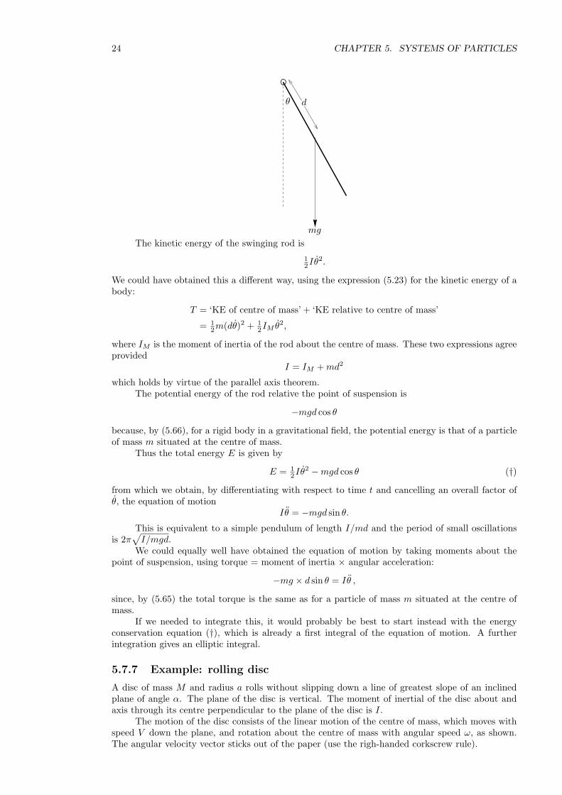
Using forcesThe external forces on the disc are shown in the diagram on the next page.Again regarding the disc as a system of particles, we have two general results derived from
Newton’s second law:
MR = Fe =n∑
i=1
mig + N + F = Mg + N + F (5.67)
where R is the position of the centre of mass, Fe is the sum of the external forces namely gravity,and the frictional F and the normal reaction N which act yP , the point of contact between the discand the plane;
dHM
dt= GM =
n∑
i=0
yi × (mig) + yP × F + yP ×N (5.68)
= yP × F (5.69)
where HM is the total angular momentum about the centre of mass and GM is the total externaltorque about the centre of mass (i.e. the total moment of the external forces). The first term onthe right of equation (5.68) vanishes because
∑miyi = 0 and last term vanishes because the force
N is parallel to yP . Note that
20The minus sign in the following equation arises because x is distance down the plane.
26 CHAPTER 5. SYSTEMS OF PARTICLES
V
α
ωa
Mg
F
R
The component of equation (5.67) parallel to the plane, and the component of (5.69) in thedirection k parallel to the axis of rotation give, respectively,
mV = Mg sin α
Iω = aF,
using HM · k = Iω. The second of the above equations holds because the direction of the axis ofrotation is constant (even though the axis itself is translating). Eliminating F from these equations,and using ω = V/a gives
(m + I/a2)V = Mg sin α (5.70)
which is the same equation as motion as that derived using conservation of energy.We could have obtained this same result more directly using again
H = G
where now the angular momentum and the torque are about the point of contact between the discand the plane. Again H · k = I ′ω, but I ′ is now the moment of inertial of the disc about an axisparallel to k passing through the point of contact, which by the parallel axis theorem is given by
I ′ = I + ma2.
This gives the same equation as (5.70), since the shortest distance between the line of action of theforce of gravity acting through the centre of the disc and the point of contact is a sin α.
Note that the ω in this calculation is the same as the ω that led directly to (5.70), becauseangular velocity is independent of position.