Embed Size (px)
Citation preview
Systems Geometry: A Dimensional Approach to T&E Systems of Systems
Understanding
SoS Engineering Collaborators Info Exchange24 June 2014
Dr. Christina BouwensASA(ALT) SoSE&I / MSCI
Dr. Jose SepulvedaUniversity of Central Florida
College of Engineering and Computer [email protected]
Dr. Nancy BucherASA(ALT) SoSE&I
Approved for public release; distribution unlimited. Review completedby the AMRDEC Public Affairs Office 31 Oct 2013; PR0085.

2
Presentation Overview
• Introduction, Problem and Background• Systems of Systems• Test and Evaluation SoS Characteristics• Systems Geometry• CAGE II Case Study• Future Research

3
Systems of Systems
• What are Systems of Systems?−“An SoS is defined as a set or arrangement of systems that
results when independent and useful systems are integrated into a larger system that delivers unique capabilities.” (DAG 2004)
• Five Characteristics (Sage & Cuppan, 2001)−Operational Independence of Constituents−Managerial Independence of Constituents−Geographic Distribution−Emergent Behavior−Evolutionary Development

4
The Challenge of Systems of Systems
• Connectivity• Common “language”• Coordination
• Multiple developers• Emergent behaviors

5
Characteristics of Distributed SoS in T&E (1 of 2)
Characteristic Explanation ExamplesGeographic location This is the location of the component system of interest. This could also account
for multiple “sites” at a particular location.Military post, laboratory, city, country
Participants / Stakeholders
There are many “sub” dimensions of stakeholders within an event. It could represent a particular service, command, or division. It could also represent a particular lab, program, or company. It includes funding sources, sponsors, users, developers, etc.
Army, Navy, Air Force, Marines, Canadian Forces, UK Forces, TRADOC, ARL, Contractors, Universities, etc.
Purpose / Mission Each event or capability has a specific mission or purpose. There is some overlap between capabilities – but not in the resources. There is also overlap in the resources used but not the proposed mission (reuse). This represents the motivation for the desired emergent SoS behaviors.
Training, developmental testing, operational testing, research, network evaluation, etc.
Constituent Systems Systems can consist of many types. Operational equipment represents constituent systems that are typically used in the field by a warfighter in a real warfare situation. Modeling and simulation is used to explore concepts, augment a SoS environment containing operational equipment, or develop courses of action. A variety of tools are used for operating and monitoring the SoS environment, collection of data for analysis, assessment of the event activities, and so on.
Live, virtual and constructive simulations, command and control equipment, network monitoring tools, test tools, statistical tools, data loggers, etc.
Capabilities –Functional
Functional capabilities highlight the role that an event participant plays in the overall SoS event. These may be tied at a very high level to operational activities but only in overall role. These functional capabilities are more at the event level.
Technical operation and control, blue ground maneuver, engineering support, communication effects, etc.

6
Characteristics of Distributed SoS in T&E (2 of 2)
Characteristic Explanation ExamplesCapabilities –Operational
Operational capabilities directly address the military or operational scenario represented in the event while designating which components of the scenario are represented by which systems.
Air defense, logistics support, blue ground forces, etc.
Network Connectivity There are several types of networks supporting SoS events – these include: Physical networks – the actual networking infrastructure (hardware, routers,
etc.) used to link the component systems Operational communications – this represents the operational network that
is used for scenario connectivity. Support / Coordination communications – this network allows the functional
teams to coordinate efforts for the system.
Physical: SIPR/NIPRnet, SDREN/DREN, etc.
Operational: various tactical networks
Support: chat, text, VOIPInteroperability (layers)
This addresses the ability of the constituent systems to interact in a valid and meaningful way during an event. There are levels of interoperability from simple exchange of raw data to common interpretation of received information. This consists of a number of interoperability architectures and integrating capability (such as gateways) that address interoperability at the various layers.
DIS, HLA, TENA, CTIA, IP, etc.

7
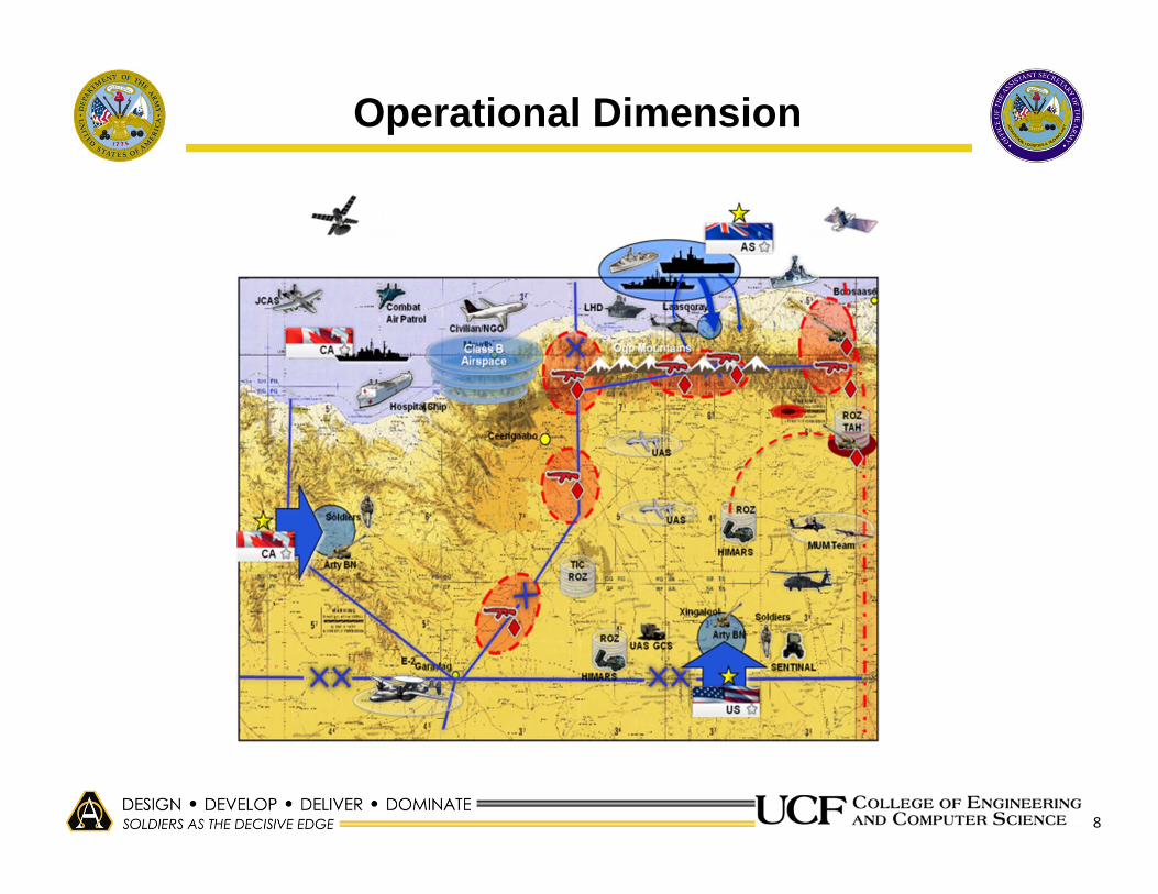
System Dimensions
• Geometrically, we understand 1, 2 or 3 dimensions – maybe 4 or more
• Systems, particularly SoS have many dimensions that define them
• SG defines 3: Operational, Functional, and Technical
x
x
y
x
yz
8
Operational Dimension

9
Functional Dimension
Analysts / Experiment Support
Engineer / Infrastructure Support
Warfighters / Mission Support

10
Technical Dimension
Tactical Apps
Live Radios
Exercise Control and Data Tools
C5ISR
11
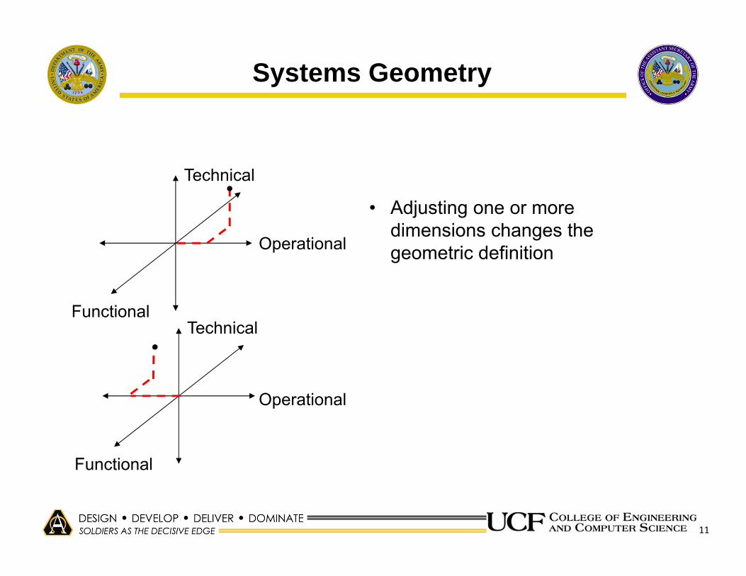
Systems Geometry
• Adjusting one or more dimensions changes the geometric definitionOperational
Functional
Technical
Functional
Technical
Operational

12
Systems Geometry Defined
Systems Geometry is defined as a methodology for exploring emergent system behaviors (planned and unplanned) of multi-dimensional SoS through the capture and analysis of intra- and cross-dimensional characteristics of a targeted SoS.
Purpose of SG:• Help SoS developers understand and address emergent
SoS behaviors• Support better planning for SoS development• Assist in proactive mitigation of SoS behaviors that are
not intended (risk)

13
The Problem
• Current system engineering methods fail to address the all the ‘dimensions’ of these complex SoS−Particularly the interactions between the dimensions which impact
the resulting emergent behavior
• Major issues are uncovered when integrating these SoS – this is much too late in the development cycle
• A methodology is needed to address the emergence of these ‘unintended’ SoS behaviors early in the system development lifecycle to allow for proactive mitigation of these behaviors.

14
The SG Methodology SG Architecture Framework

15
The SG MethodologySG Process Definition

16
The SG MethodologySG Methods Definition (2 of 2)

17
Case Study: Coalition Attack Guidance Experiment
• Series of experiments exploring coalition coordination
• CAGE I served as the “lessons learned” basis for focusing analysis
• CAGE II was the focus of SG implementation
• Exhibited all the characteristics of SoS and the SG dimensions

18
CAGE I Issue Areas To Be Considered
• Constituent System (interface) Maturity −Coordination throughout planning critical−Pre-event testing is vital−Configuration management needs to be maintained
• Integration and Interoperability−Clear path for integration needed−Consistent use of proper standards well in advance of event
• Experimentation Support−Better collaboration of experiment and data collection activities
with other event areas

19
System x System Interaction Matrix
1 2 3 4 5 6 7 8 9 10 11 12 13 14 15 16 17 18 19 20 21 22 23 24 25 26 27 28 29 30 31 32 331 AU‐JSAF2 AU‐RTI‐S RTI 1 1 13 AU‐JSAF Link 16 GW 14 AU‐JSAF DIS GW 1 15 AU‐TENA‐DIS GW 1 16 US‐RTC‐TENA‐DIS GW 17 CA‐CFWC‐SIMDIS1 1 1 18 CA‐CFWC‐SIMDIS2 19 CA‐CFWC‐Bender 1 1 1 1 1 1 110 CA‐CFWC‐VBS2‐Coord 111 CA‐CFWC‐VBS2‐UAV OP1 1 112 CA‐CFWC‐VBS2‐Op 113 CA‐CFWC‐VBS2‐UAV OP2 114 CA‐CFWC‐JCATS Client 1 115 CA‐CFWC‐JCATS Client 2 116 CA‐CFWC‐JCATS Client 3 117 CA‐CFWC‐JCATS Client 4 118 CA‐CFWC‐JCATS Server 1 1 1 1 119 CA‐CFWC‐JSAF3 120 CA‐CFWC‐JSAF4 121 CA‐CFWC‐JSAF5 122 CA‐CFWC‐RTI‐S RTI 1 1 1 1 123 CA‐CFWC‐CSV Sim logger 124 CA‐CFWC‐TENA‐DIS GW 1 1 125 CA‐CFWC‐VCCI GW 126 CA‐CFWC‐JSAF‐DIS GW 1 127 CA‐CFWC‐JSAF‐OthGold GW 128 CA‐CFWC‐JSAF‐Link 16 GW 129 CA‐CFMWC‐JSAF‐DIS GW 1 130 CA‐CFMWC‐VBS2‐UAV 131 CA‐CFMWC‐JSAF1 132 CA‐CFMWC‐JSAF2 133 CA‐CFMWC‐RTI‐S‐RTI 1 1 1

20
y = 13.637x‐1.077R² = 0.8521
0
2
4
6
8
10
12
14
16
0 5 10 15
# Nod
es
Degree
System Analysis – Degree Centrality

21
Operational vs Functional Analysis:Importance of Objectives
Expert Choice

22
Experimental Design Analysis:Metrics Mapping to Objectives
Significant influence of Metrics 3, 8 and 9
High dependency on many metrics for Objective 4

23
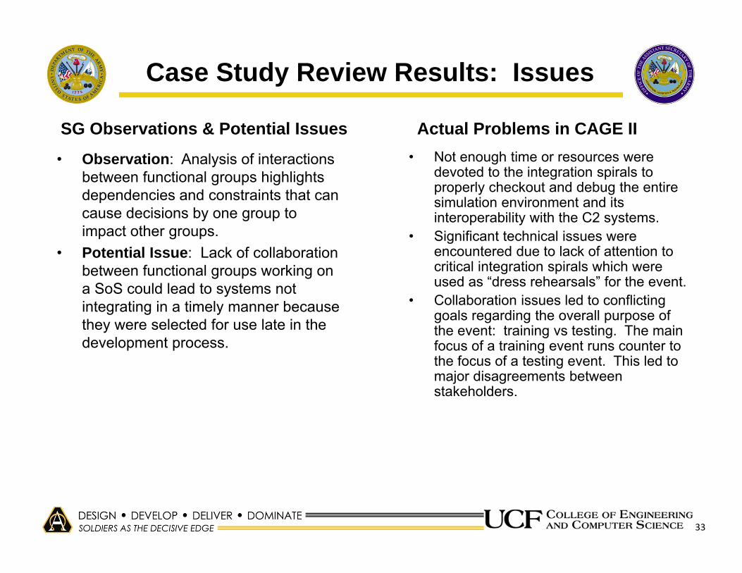
Case Study Review Results: Issues (1 of 2)
• Observation: System x System network analysis highlighted systems with high centrality measures, indicating significance of proper operation of those nodes
• Potential Issue: Major SoS execution problems can occur if system nodes with high centrality measures have problems.
– There is a need to ensure such nodes are well tested and configuration controlled before an event.
• During the exercise, the routing tables were changed on one of the network routers causing connectivity issues with conference room calls and malfunction in Sim Radios.
• Incompatibility of one of the TENA gateways with one of the OneSAFsimulations caused failure of the simulation and required isolating the simulation on a separate network to allow for its continued its participation in the exercise.
• TENA gateway required five updates during the conduct of the experiment, interfering with the timely conduct of experiment activities.
SG Observations & Potential Issues Actual Problems in CAGE II

24
Case Study Review Results: Issues (2 of 2)
• Observation: Network analysis of experimental design (metrics vs obj) highlighted complexity with metrics use and objective evaluation.
• Potential Issue: Overly complex experiment design (too many hypotheses with too many metrics) could make it difficult to evaluate achievement of objectives if certain metrics are unavailable
• Overlapping hypotheses and metrics where multiple hypotheses had numerous metrics and many metrics were associated with multiple hypotheses led to confusion and also trouble with assigning causality to observed behavior.
SG Observations & Potential Issues Actual Problems in CAGE II

25
Case Study Review Results: Opportunities
• Observation: Operational System x Operational System network analysis highlighted systems with high centrality measures, indicating significance of those nodes
• Potential Opportunity: Stable nodes with high centrality measures can contribute to successful execution of the experiment.
– JADOCS was identified as a highly central C2 node in the network.
• JADOCS provided an excellent integration of the tactical air picture from all partners.
• JADOCs operated well across all the objective areas.
SG Observations & Potential Opportunities Actual Advantages in CAGE II

26
Why Should We Care?
• There is great cost associated with the development of complex distributed SoS which grows significantly when issues are not discovered until systems integration.
• Understanding SoS from an emergence standpoint highlights shortcomings of traditional system analysis techniques and opens the door to implementing new approaches.
• New techniques and tools for effective engineering analysis need wider adoption. −Engineering education needs to target these tools and techniques
to better equip today’s systems engineer.

27
Future Research – Near term
• Implement SG using DoDAF as the architecture framework, fine tuning the methodology with real system development activity
• Perform a multi-dimensional analysis of the relationship between the operational and technical domains – relating scenarios to system configurations or objectives (training, testing, etc.) to system configurations.
• Investigate the use of options analysis for configuration selection in a T&E technical infrastructure (Purdue)
• Conduct a comparative study of SoS modeling methods to determine what types are most appropriate for different dimensional analyses
• Explore network analysis statistics for values that may characterize particular types of configurations of SoS
• Expand the study of emergence and complexity to explore additional analysis methods

BACKUP

29
The SG MethodologySG Methods Definition (1 of 2)
SoS Issues Recommended Methods for T&EInteroperability & Integration
SysML sequence diagrams along with interface attribute information for all three dimensions will provide important insight into the SoS needs for integration and interoperability.
Constituent System Maturity
Matrix and network methods to show stakeholder relationships with one another and with candidate constituent relationships. Capability analysis (and other SoS configuration alternative techniques) will consider maturity when providing constituent system options to the SoS developer.
Collaboration Matrix and network methods showing stakeholder relationships along various collaborative areas to include operational collaboration, functional and technical.
Training Matrix methods mapping processes, systems and stakeholders can determine what kind of training is needed and who needs to be trained. Traditional project management methods of planning and tasking can ensure that proper training takes place.
Resource Assessment / Utilization
Matrix methods help to identify system resources required to support operational and functional activities. Network methods could be used to examine which resources are most critical to the success of the event.
Analysis & Experimentation Support
SysML use case and sequence diagrams can be used to show the business process for analysis and experimentation activities, ensuring that they are supported. Matrix methods will relate the needed capabilities with specific systems for implementation. Network analysis methods can reveal the importance of certain metrics or hypotheses for performing capability analysis.
Implementing Architectural Views
Utilize DoDAF which is recommended for use in the DoD T&E environment and can capture the information required for other analysis techniques.

30
The SG MethodologySG Tools Definition (1 of 2)
SG Process Step
SG Analysis Methods
Tool Features Examples
Identify Areas for Analysis
Review lessons learned and capability requirements through stakeholder meetings
Brainstorming tools, office products for documentation, desktop sharing, whiteboard applications, audio and video teleconferencing
MindManager, Text 2 Mindmap, Skype, WebEx, Adobe Connect, Sharepoint
Identify SG Dimensions
Discussion with stakeholders, review of analysis areas, previous experience
Brainstorming tools, office products for documentation, desktop sharing, whiteboard applications, audio and video teleconferencing
MindManager, Text 2 Mindmap, Skype, WebEx, Adobe Connect, Sharepoint
Use an Arch Framework to Capture Dimensional Information
Use DoDAF and/or ESM to capture key dimensional information.
Office products for documentation, tools for developing architecture views
Office products (MS Excel, MS Word), Innoslate, Genesys, IBM Rational Tools, MagicDraw, Open System Engineering Environment

31
The SG MethodologySG Tools Definition (2 of 2)
SG Process Step
SG Analysis Methods
Tool Features Examples
Develop SoS Models and Functional Models
Use SysML, AB and SD to model SoS and key SoS functional areas
System level models development supporting model-based systems engineering to include UML, SysML, discrete event simulation, system dynamic and agent based models
IBM Rational Tools, MagicDraw, Arena, AnyLogic, NetLogo, Expert Choice
Perform Dimensional and Cross Dimensional Analysis
Use previous experience and network analysis methods to explore cross dimensional relationships
Functional block diagrams, data flow diagrams, N2 Charts, IDEF Diagrams, UML diagrams, SysML diagramsTools for generating network graphs and calculating node and network statistics
MS Excel, Gephi, ORA (CASOS tool), Statistical tools
Office products (MS Excel, MS Word, etc.), Innoslate, Genesys, IBM Rational Tools, MagicDraw, Open System Engineering Environment
Gephi, Ora, Pajek, NetLogo, NodeXL, UCInet, R
Review Results Meet with stakeholders to review results and update dimensional information and methods as needed
Brainstorming tools, office products for documentation, desktop sharing, whiteboard applications, audio and video teleconferencing
MindManager, Text 2 Mindmap, Skype, WebEx, Adobe Connect

32
The Case Study: Coalition Attack Guidance Experiment
• Operational Independence: Standalone simulations and operational systems
• Managerial Independence: Developed in different countries and by different groups in each country.
• Geographic Distribution: US, Canada and Australia locations
• Emergent Behavior: Coalition operations only possible using combination of systems.
• Evolutionary Development:Evolving constituent participation over time as the SoS event was developed
33
Case Study Review Results: Issues
• Observation: Analysis of interactions between functional groups highlights dependencies and constraints that can cause decisions by one group to impact other groups.
• Potential Issue: Lack of collaboration between functional groups working on a SoS could lead to systems not integrating in a timely manner because they were selected for use late in the development process.
• Not enough time or resources were devoted to the integration spirals to properly checkout and debug the entire simulation environment and its interoperability with the C2 systems.
• Significant technical issues were encountered due to lack of attention to critical integration spirals which were used as “dress rehearsals” for the event.
• Collaboration issues led to conflicting goals regarding the overall purpose of the event: training vs testing. The main focus of a training event runs counter to the focus of a testing event. This led to major disagreements between stakeholders.
Actual Problems in CAGE IISG Observations & Potential Issues