Embed Size (px)
Citation preview

Systems Fire Protection Working Group
Taj Mahal - Atlantic City, NJ November 4, 2003
FAA Concept OBIGG System Flight Testing on NASA 747 SCA
William CavageAAR-440 Fire Safety Research
Federal Aviation Administration

AAR-440 Fire Safety R&D
FAA-NASA 747 Inerting Flight Test___________________________________
Outline• Goals and Objectives
• OBIGGs Architecture
• OBIGGs Installation– Pallet
– NEA Deposit
• Instrumentation / DAS– CWT
– System
– OBOAS / FAS
– Data Acquisition
– Power Distribution
• Status

AAR-440 Fire Safety R&D
FAA-NASA 747 Inerting Flight Test___________________________________
Testing Goals and Objectives• Prove the simplified inerting concept and validate/expand
upon existing system performance models
• Develop/validate system sizing data
• Validate previous in flight inert gas distribution modeling done by FAA
• Measure the progression of flammability in the CWT of a typical commercial transport airplane

AAR-440 Fire Safety R&D
FAA-NASA 747 Inerting Flight Test___________________________________
OBIGGS - System Architecture• 400 deg F bleed air enters electrically controlled &
operated Shut-off Valve on OBIGGS Control Box
• Air goes through heat exchanger by a cooling air throttling valve to control temperature manually using a ASM air input temperature sensor– Some bleed air can bypass the heat exchanger if selected
• Conditioned air passes through dust/oil contaminant filter
• Air enters ASM and has OEA separated and dumped overboard

AAR-440 Fire Safety R&D
FAA-NASA 747 Inerting Flight Test___________________________________
OBIGGS - System Architecture (cont’d)• NEA passes through high flow shut-off valve (Parker Box
operator) and High/Low flow metering valves
• System controlled by control box in cabin that is connected to system with cable routed through wheel well– Turns system on/off
– Select heat exchanger bypass on/off
– Select fan on/off
– Select high/low flow mode
– ASM input air temperature readout

AAR-440 Fire Safety R&D
FAA-NASA 747 Inerting Flight Test___________________________________
Assembled FAA OBIGGs Drawing
AAR-440 Fire Safety R&D
FAA-NASA 747 Inerting Flight Test___________________________________
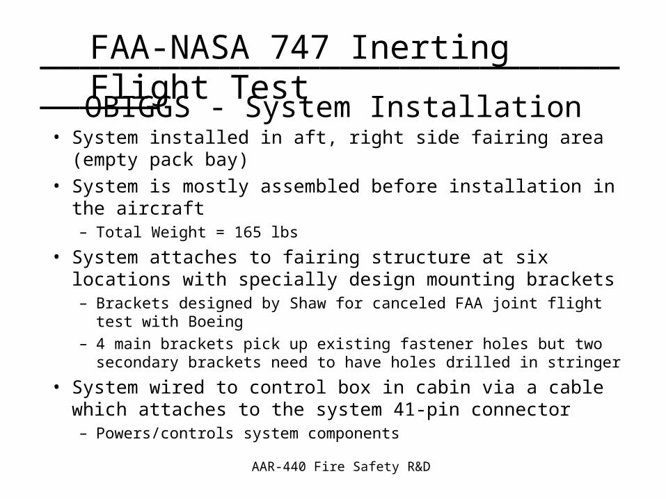
OBIGGS - System Installation• System installed in aft, right side fairing area (empty pack bay)
• System is mostly assembled before installation in the aircraft– Total Weight = 165 lbs
• System attaches to fairing structure at six locations with specially design mounting brackets– Brackets designed by Shaw for canceled FAA joint flight test with Boeing
– 4 main brackets pick up existing fastener holes but two secondary brackets need to have holes drilled in stringer
• System wired to control box in cabin via a cable which attaches to the system 41-pin connector– Powers/controls system components

AAR-440 Fire Safety R&D
FAA-NASA 747 Inerting Flight Test___________________________________
OBIGGS - System Installation (cont’d)• System interfaces with bleed system via a main bleed duct
manifold in that area– 4-foot segment from SCA is removed and FAA segment installed
– Needs to align precisely with system bleed air input fitting
• System cooling air passes in a scoop and out the outflow box– Two FAA panels with these parts already mated with aircraft

AAR-440 Fire Safety R&D
FAA-NASA 747 Inerting Flight Test___________________________________
Top View of System Installed
Inboard AircraftStructure
Outboard AircraftStructure

AAR-440 Fire Safety R&D
FAA-NASA 747 Inerting Flight Test___________________________________
Simplified OBIGG System Installation
AAR-440 Fire Safety R&D
FAA-NASA 747 Inerting Flight Test___________________________________
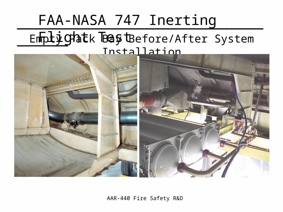
Empty Pack Bay Before/After System Installation

AAR-440 Fire Safety R&D
FAA-NASA 747 Inerting Flight Test___________________________________
OBIGGS - Deposit System• Install deposit “T” and dual isolation valves allows for
improved functionality of testing (counter-wire valves)– Install a “T” in system NEA deposit
– 1 side of “T” goes to outflow box via a normally closed isolation valve
– Other side of “T” goes to flow meter, check valve, and a second normally open isolation valve
• Install AN bulkhead fitting in replaced pack bay canted bulkhead panel– Route NEA from check valve to fitting with flexible hose

AAR-440 Fire Safety R&D
FAA-NASA 747 Inerting Flight Test___________________________________
Deposit System Overview

AAR-440 Fire Safety R&D
FAA-NASA 747 Inerting Flight Test___________________________________
NEA Deposit “T”

AAR-440 Fire Safety R&D
FAA-NASA 747 Inerting Flight Test___________________________________
Flow Meter/Deposit Installation

AAR-440 Fire Safety R&D
FAA-NASA 747 Inerting Flight Test___________________________________
NEA Diversion Valve Installation

AAR-440 Fire Safety R&D
FAA-NASA 747 Inerting Flight Test___________________________________
• To deposit NEA in tank without permanent modification replaced purge door with “instrumentation panel” that passes the NEA, thermocouples, and gas samples (not FAS) into the tank from the wheel well adjacent to the pack bay– NEA fitting is 1” SwageLok Bulkhead Fitting
• NEA routed to deposit nozzle mounted in the top of tank in Bay 6 (aft, right bay) via a 1-inch flexible line– nozzle mounted in bracket attached to aircraft stiffener bracket
between strings at top of tank
• Also Blocked Half Vent System
OBIGGS - Deposit System (cont’d)

AAR-440 Fire Safety R&D
FAA-NASA 747 Inerting Flight Test___________________________________Install Instrumentation Port

AAR-440 Fire Safety R&D
FAA-NASA 747 Inerting Flight Test___________________________________
Existing Stringer/Stiffener/Bracket Assembly

AAR-440 Fire Safety R&D
FAA-NASA 747 Inerting Flight Test___________________________________
Install NEA Deposit Nozzle and Associate Hardware

AAR-440 Fire Safety R&D
FAA-NASA 747 Inerting Flight Test___________________________________
Install Vent Blocking Plates

AAR-440 Fire Safety R&D
FAA-NASA 747 Inerting Flight Test___________________________________
Instrumentation and Data Acquisition• Various thermocouples and pressure transducers used
– Evaluate system performance
– Measure tank flammability parameters
• OBIGGS system flow meter and 2-channel oxygen analyzer for NEA and OEA analysis
• Onboard Oxygen Analysis System (OBOAS) most critical measurements– 8-channel system analyzes 8 locations in tank
• Flammability Analysis System (FAS) will measure progression of CWT flammability in flight– 1 location in forward section of tank

AAR-440 Fire Safety R&D
FAA-NASA 747 Inerting Flight Test___________________________________
CWT Instrumentation• Installation Instrumentation in the CWT of the NASA
SCA– Install Instrumentation Panel in Place of Purge Door
– Route and Mount Thermocouples
– Install Sample Port Float Valve Assembly and Route Lines as well as sample return lines
• Sub-Contractor (FFC) supported FAA installation– Highly experienced in this type of work
– Statement of Work gives more details

AAR-440 Fire Safety R&D
FAA-NASA 747 Inerting Flight Test___________________________________
Route and Mount Thermocouples Front Spar
Spanwise Beam #3
Spanwise Beam #2
Midspar
Spanwise Beam #1
Rear Spar
237"
57"
42"
55"
42"
255"
26.5"
(STA 1000)
(STA 1241)
To LeftSurge Tank
To RightSurge Tank
Vent Channels
41"
1 2
3 4
5 6
7 8
Dry Bay
Bay 1
Bay 2
Bay 3 Bay 4
Bay 5 Bay 6
9 10
11 12
13 14
15 16
17
19
20
18
21
22
24
23
nn Ullage Fuel n Floor, Wall, & Ceiling Mounted

AAR-440 Fire Safety R&D
FAA-NASA 747 Inerting Flight Test___________________________________
Install Sample Port Float Valve Assembly

AAR-440 Fire Safety R&D
FAA-NASA 747 Inerting Flight Test___________________________________
Instrumentation - Additional Thermocouples• Use 16th Inch SS Sheath T-Type Thermocouple
Probes
• Install one in each used pack bay and one in the OBIGGS pack bay
• Install 4 in the area of the bleed air connection– Monitor for Bleed Air Leaks
• System has 6 thermocouples installed
• Thermocouple in cabin
• Thermocouples in measurement systems (OBOAS/FAS)

AAR-440 Fire Safety R&D
FAA-NASA 747 Inerting Flight Test___________________________________
• Measure Absolute Pressure at 4 locations on OBIGGS and measure static pressure in pack bay– Potential to add 1 to bleed manifold if possible
• Purchase off-the-shelf lab pressure transducers– Sensotec TJE Precision, Absolute series
– Run on 28 VDC, 12 VDC nominal bridge voltage, internally regulated
– 0-5 VDC output
• Mount transducers on panel in cabin– Run 5 sense lines to pack bay
Instrumentation - Pressure Transducers

AAR-440 Fire Safety R&D
FAA-NASA 747 Inerting Flight Test___________________________________
Thermocouple Probe and Pressure Transducer

AAR-440 Fire Safety R&D
FAA-NASA 747 Inerting Flight Test___________________________________
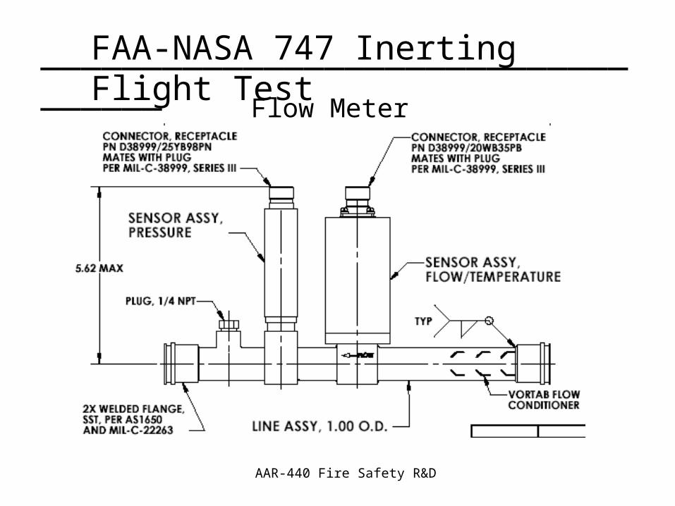
Instrumentation - NEA Flow Meter• Engineered Specifically for The FAA OBIGGS
– Designed from Existing Commercial and Military Assemblies by FCI
– Flight worthy instrumentation (No TSO)
– Uses vortex shedding heat release principal
– Also measures absolute temperature and pressure of flow
• 1” diameter flow tube integrates with existing deposit system on pallet
AAR-440 Fire Safety R&D
FAA-NASA 747 Inerting Flight Test___________________________________
Flow Meter

AAR-440 Fire Safety R&D
FAA-NASA 747 Inerting Flight Test___________________________________
System Instrumentation Diagram
Static Pressure Temperature
Spare [O2]
Static Pressure Temperature
OEA [O2]
Temperature
Static Pressure
Temperature Temperature (FAA Reader)
Static Pressure Temperature
NEA [O2]
Penetration Hole

AAR-440 Fire Safety R&D
FAA-NASA 747 Inerting Flight Test___________________________________
Instrumentation - OBOAS• Two 4-Channel Systems Measure Oxygen Concentration
Continuous at 8 Different Fuel Tank Locations– Large diaphragm pump draws sample
– Actively controls sample inlet and outlet pressure.
– Flow through sensor design
– Fluid traps, Ejector/Evacuator, Flame Suppressors for Safety
• Mounts in standard 19” flight test half rack including sample system (OBUSS) contained in large, purged box

AAR-440 Fire Safety R&D
FAA-NASA 747 Inerting Flight Test___________________________________
OBOAS Block Diagram
Fuel Tank VaporFuel Tank LiquidPressurized AirElectrical PowerElectronic Signals

AAR-440 Fire Safety R&D
FAA-NASA 747 Inerting Flight Test___________________________________
OBOAS Mounted in FAA AMCO Racks

AAR-440 Fire Safety R&D
FAA-NASA 747 Inerting Flight Test___________________________________
Instrumentation - FAS• System uses a Non-Dispersive Infrared Analyzer
(NDIR) to measure fuel tank flammability in the form of total hydrocarbons (THC)
• Sample stream must be heated at all points leading to the NDIR to prevent condensation of fuel vapors– This is achieved in part via three heated hoses
• Installs in a rack and pallet for flight test

AAR-440 Fire Safety R&D
FAA-NASA 747 Inerting Flight Test___________________________________
Aircraft Cabin
FAS
Air
OBOAS
Exi
stin
gPo
wer
Rac
k
Window Plug
DASOBIGGS
Air
Air
Air
OBOAS
Compressed Air Bank (Cargo Bay)
Penetration STA 1275
Penetration STA 1248
Penetration STA 980
Power Cable
System Wiring
Sample Tubing
Purge Air Line
Instrumentation Wiring
To Avionics Bay
STA 990 STA 1010 STA 1080 STA 1120 STA 1250
FASAnalyzer
Sample System
Cabin Instrumentation/Rack Diagram

AAR-440 Fire Safety R&D
FAA-NASA 747 Inerting Flight Test___________________________________
• Power Distributed to the Various Equipment from Utility Rack at ST. 990 – 3-Phase 115 VAC 400Hz to Each OBOAS (13 amps/leg)
– 20 Amps of 115 VAC 60 Hz to FAS
– 5 Amps of 115 VAC 60 Hz to DAS and Computer
– OBIGGS takes 5 Amps 28 VDC and 3-Phase 115 VAC, 400Hz (5 Amps/ Leg)
• Each OBOAS converter is tied to a switching unit that allows for power to be distributed between racks and to the OBIGGS O2 analyzer
Instrumentation - Power Distribution

AAR-440 Fire Safety R&D
FAA-NASA 747 Inerting Flight Test___________________________________
Power Distribution Diagram OBIGGS
Analysis Pump
OBOASPump 1
OBOASPump 2
OBOAS Rack Assembly
OBIGGSControl
Box
DAS
Computer
DAS &OBIGGSRack
NDIRAnalyzer
SampleSystem
FASRack
Power StripPower Strip
115 VAC, 400 Hz Bus
Existing60 Hz Power
Converter
28 VDC Bus
Existing Power Rack
OBIGGS AnsySample Train
AAR-440 Fire Safety R&D
FAA-NASA 747 Inerting Flight Test___________________________________
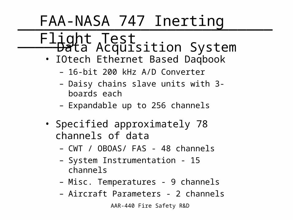
• IOtech Ethernet Based Daqbook– 16-bit 200 kHz A/D Converter
– Daisy chains slave units with 3-boards each
– Expandable up to 256 channels
• Specified approximately 78 channels of data – CWT / OBOAS/ FAS - 48 channels
– System Instrumentation - 15 channels
– Misc. Temperatures - 9 channels
– Aircraft Parameters - 2 channels
Data Acquisition System

AAR-440 Fire Safety R&D
FAA-NASA 747 Inerting Flight Test___________________________________
Data Acquisition System
Data
Data
Daqbook / 2000E
DBK60 Expansion

AAR-440 Fire Safety R&D
FAA-NASA 747 Inerting Flight Test___________________________________
• CWT installation approved and completed
• OBIGGs, OBOAS, FAS, instrumentation/racks, & DAS installation approved– One sticking point
• OBOAS modified from Airbus testing and FAS completed
• Additional parts purchased
• NEA deposit completed,
• Instrumentation racks built up
• Preparing to ship all equipment for installation
Status