Embed Size (px)
Citation preview

1
A Systems Approach to Torsional AnalysisBrad D. Murray, M.Sc., P.Eng. Brian C. Howes, M.Sc., P.Eng. Valerie Zacharias, M.A.
Beta Machinery Analysis Ltd.,300, 1615 – 10th Ave. S.W.,
Calgary, AB, Canada, T3C 0J7
Canadian Machinery Vibration Association National Conference, Halifax, September, 1995.Gas Machinery Conference, Corpus Christi, Texas, October, 1995.
ABSTRACTCase studies (Part I) illustrate problems associated with thetorsional design of fixed speed reciprocating compressorsystems. In many cases, solutions to these problems demandan iterative systems approach. Part II presents the systemsapproach, in which the dynamic torsional response of theentire system is determined and the individual components areredesigned until the overall response is acceptable.
Part 1 – Case Studies1. THE SYSTEMS APPROACH – WHY?
In today’s competitive market place productivity is ofthe utmost importance. The ability to bring a systemon-line on time or even early is critical. A delay of aday can result in revenue losses in the thousands ofdollars. Accordingly, there is a temptation to build acompressor system based on rules of thumb:
• calculate the mean torque• calculate “design torque” (mean torque times
a service factor based on experience and onthe number of compressor throws)
• ensure the coupling and shafts can toleratethe “design torque”.
In contrast the systems approach considers the totaleffect of the interaction of the components(compressor reciprocating elements, crankshaft,coupling, motor shaft, and motor). Each individualcomponent may be designed appropriately, but the
overall effect of the combination also needs to beverified. For example, the overall torsional responseof a system determines what size coupling isrequired, but the size and type of coupling must beknown before the system’s torsional response canbe predicted. Similarly the shaft’s and coupling’smass-elastic characteristics have a significantinfluence on motor dynamic response (i.e. electricalcurrent pulsations).
Three cases focusing on fixed speed, electric drivereciprocating compressors are presented. Theyclearly demonstrate how interaction can generatesevere problems and why an iterative approach isneeded to solve them.
Trouble-free operation, an important component ofproductivity, is jeopardized unless a systemsapproach to torsional analysis is used.
http://www.BetaMachinery.com

2
2. CASE 1 – RESONANCE CAUSED EXCESSIVEVIBRATION AT THE COMPRESSORAUXILIARY DRIVE
Unit: Oil pump driven from the opposite drive end(ODE) of the compressor shaft, with a:
• six throw 3000 HP reciprocating compressor• squirrel cage induction motor (885 RPM)• flexible disk coupling.
Figure 1. Torque effort was greater at 3X runspeedthan at 6X runspeed.
Torsional vibration caused the oil pump drive shaft tofail within one hour of service. The pump wassubsequently replaced but again failed within onehour of service.
The compressor torque effort spectrum shown inFigure 1 indicates that the torque effort (input) isprimarily concentrated at the 3rd and 6th orders of runspeed, with the 3X component much higher.
However, the torsional response curve, Figure 2, ismore than 8 times higher at 6X runspeed than at 3X.This difference suggests resonance, and leads to theconclusion that the torsional natural frequency (TNF)is close to 6X run speed (88.5 Hz).
Figure 2. Torsional response at compressor ODEwas excessive at 6X runspeed.
Based on measured data and a finite elementtorsional model, the system’s TNF was determinedto be approximately 87 Hz (5.9X run speed), tooclose to the known high input torque at 6X runspeed.To make matters worse, the pump’s drive shaft hada TNF of 93 Hz, or 6.3X runspeed. The combinationof all these factors was intolerable.
To reduce the dynamic 6th order amplification,coincidence of the TNF with the 6th order torqueeffort had to avoided. We added three small donuts(each 4630 lb.in²) to the compressor shaft, as shownin Figure 3. This modification effectively lowered thesystem’s TNF from 87 Hz to 79 Hz which, as shownin Figure 4, reduced the predicted overall angulardisplacement at the compressor auxiliary drive to23% of that in the existing system.
At the time of writing, the system has runcontinuously for several weeks with no damage tothe pump.
Figure 3. Three donuts added to the compressorshaft solved the problem.
Figure 4. Moving the TNF to 79 Hz from 87 Hzreduced the amplitude significantly.
http://www.BetaMachinery.com

3
3. CASE 2 – COUPLING TOO STIFF FORPROPOSED MOTOR/COMPRESSOR SET
The proposed system consisted of a:• four throw compressor• 1250 HP 1175 RPM squirrel cage electric
induction motor, with a shaft designed for adifferent service
• flexible disk coupling.
Two modifications are discussed:• addition of a small flywheel (20,000 lb.in²)• introduction of a “torsionally soft” coupling.
Stresses were evaluated against a design factor,which should be greater than 2. See Part II, Section4. As shown in Figure 5, only the system with the“torsionally soft” coupling met the stress criterion.
Figure 5. A design factor of less than 2 isunacceptable.
The calculated torsional natural frequency (TNF) of97 Hz was close to 5X run speed. As shown inFigure 6, there was significant deflection, resultingfrom interference of the TNF and the torque effort at5X runspeed.
The flywheel modification reduced the system TNFto about 89 Hz (4.5X runspeed), but as shown inFigure 7, peak deflection is still obvious at 3, 4, & 5Xrunspeed. These components contributed to theexcessive stress indicated in Figure 5.
The “torsionally soft” coupling modification droppedthe system TNF to about 10 Hz (0.5X runspeed). Asshown in Figure 8, the peak deflection was thenminimal.
Figure 6. Original system had noticeable deflectionat 1 through 5X runspeed.
Figure 7. Flywheel reduced deflection at 5X butincreased it at 4X runspeed.
Figure 8. Torsionally soft coupling reducesdeflection to almost nil.
http://www.BetaMachinery.com

4
4. CASE 3 – ABSENCE OF FLYWHEELALLOWED EXCESSIVE CURRENTFLUCTUATION
The proposed system consisted of a:• four throw compressor• 1375 HP induction motor, with a rated speed
of 992 RPM at full load,• flexible disk coupling.
Figure 9. Significant torque is apparent at 1, 2, 3, &4X runspeed.
The system torsional natural frequency (TNF)interfered with 5X runspeed, but the torque effort atthat frequency was small, as shown in Figure 9.Damping controlled the torsional response andtherefore shaft stress was found to be acceptable.
However, motor dynamic response was found to beunacceptable. In the proposed configuration, motorspeed fluctuated from 981 to 998 RPM. Thepredicted electrical current pulsation from this speedfluctuation was 80%, which exceeds the NEMAstandard of 66%, and which is double the new APIstandard of 40%.
Figure 10. A precisely sized flywheel effectivelycontrolled electrical current pulsation.
The solution to the excessive current fluctuation wasto add a flywheel to the compressor shaft. As shownin Figure 10, a large flywheel (260,000 lb.in²) madethe problem worse, the system TNF coincided withthe 3rd order torque effort.
A smaller flywheel (120,000 lb.in²) decreased thetorsional response, and thereby reduced the currentfluctuation to an acceptable value of 40%.
Figure 11. The new flywheel was added close to thecoupling on the compressor side.
PART II – System TorsionalAnalysis ProceduresThe torsional analysis of a fixed speed reciprocatingsystem is a seven step procedure:
• determine the system’s torsional naturalfrequencies
• determine the compressor torque effort• predict the amount of interference between
torque effort and torsional natural frequency(TNF)
• evaluate the torsional forced response,including damping
• modify the system until stress is acceptable• evaluate electrical current pulsations, and
remodify if necessary• confirm results over the range of operating
conditions.
1. DETERMINE THE SYSTEM’S TORSIONALNATURAL FREQUENCY (TNF)
TNF is a ratio of rotational stiffness to rotationalinertia. Comparing a torsional system to a simplespring-mass system, the following are analogous:
• inertia (Jo) to mass (m),• rotational stiffness (K) to linear stiffness (Kl),
and• angular deflection (T ) to translational
deflection (x).
http://www.BetaMachinery.com

5
Inertia (Jo) is essentially a function of density andgeometry, and is determined for the system byadding the inertia for each element.
(1)Josystem = Jomotor + Jocoupling + Jocompressor
System rotational stiffness is determined fromEquation (2), where K is a function of componentmaterial, diameter, length and in someconfigurations, loading.
(2) l = l + l + l . Ksystem Kmotor Kcoupling Kcomp
Several natural frequencies are usually present inthe system, and it is important to identify each ofthem.
2. DETERMINE THE COMPRESSOR TORQUEEFFORT
The torque effort (input torque) acting on the shaft inany reciprocating compressor installation is createdby a combination of cylinder gas forces andreciprocating inertial forces. These forces are bothfunctions of crank angle but are not necessarily inphase with one another. As shown in Figure 12 for aloaded cylinder, the torque effort curve of eachcylinder is periodic but is not sinusoidal; it iscomprised of several component frequencies.
Figure 12. The individual cylinder torque effort curveis not sinusoidal.
To further complicate the analysis, the compressortorque effort is the combination of all the individualcylinder torque effort curves and their respectivephasing. It is this combination curve that must beconsidered in the analysis. Figure 13 shows theoverall torque effort curve for a four cylinder unit.
Figure 13. The system torque effort curve is acombination of the cylinder curves.
For the purpose of analysis, it is necessary todetermine the frequency content of the torque effortcurve; that is, to Fourier transform the complex timedomain torque effort curve into the frequencydomain, as shown in Figure 14.
Figure 14. The FFT of the system torque effortshows relative torque at each frequency.
Since each compressor throw experiences onecomplete torque fluctuation every revolution, thetorque amplitude at the first harmonic would likelybe large as compared to the other harmonics.However, large amplitudes may also be seen at thehigher harmonics.
Note that the compressor torque effort acts atseveral locations along the shaft. The length of the
http://www.BetaMachinery.com
6
shaft between the cylinder throws has a significanteffect on the system’s torsional response, and it istherefore incorporated into the torsional model.
3. PREDICT INTERFERENCE BETWEENTORQUE EFFORT AND TNF
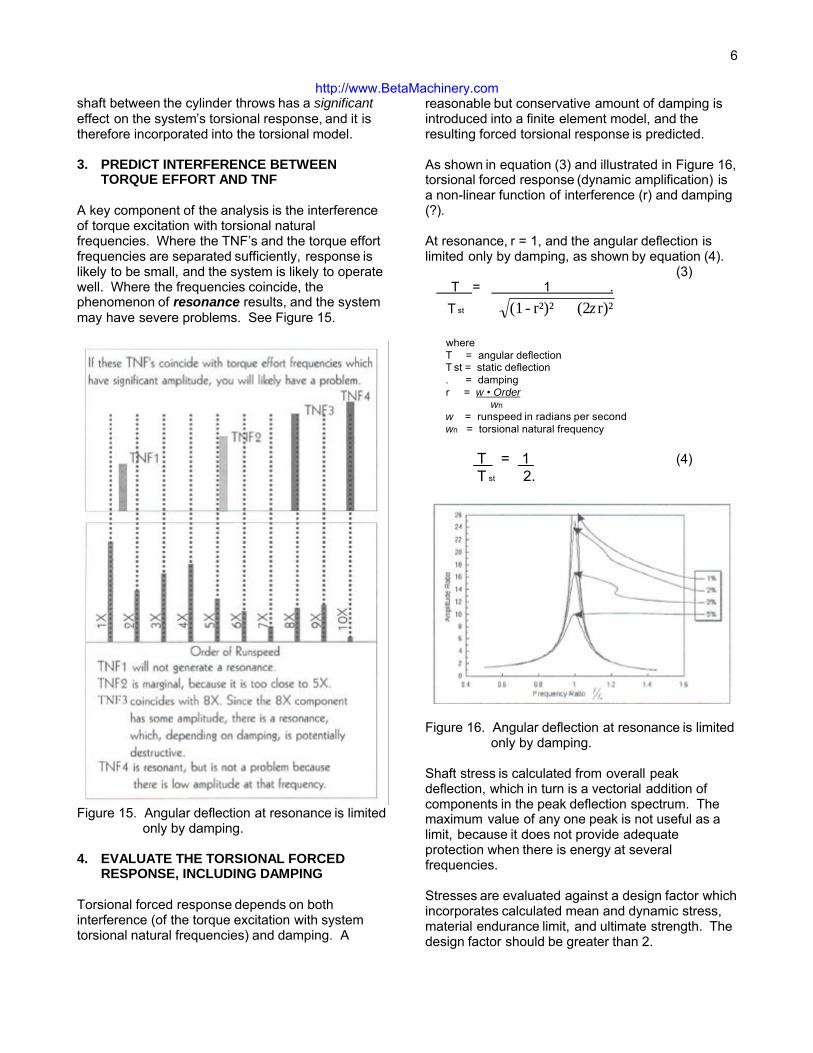
A key component of the analysis is the interferenceof torque excitation with torsional naturalfrequencies. Where the TNF’s and the torque effortfrequencies are separated sufficiently, response islikely to be small, and the system is likely to operatewell. Where the frequencies coincide, thephenomenon of resonance results, and the systemmay have severe problems. See Figure 15.
Figure 15. Angular deflection at resonance is limitedonly by damping.
4. EVALUATE THE TORSIONAL FORCEDRESPONSE, INCLUDING DAMPING
Torsional forced response depends on bothinterference (of the torque excitation with systemtorsional natural frequencies) and damping. A
reasonable but conservative amount of damping isintroduced into a finite element model, and theresulting forced torsional response is predicted.
As shown in equation (3) and illustrated in Figure 16,torsional forced response (dynamic amplification) isa non-linear function of interference (r) and damping(?).
At resonance, r = 1, and the angular deflection islimited only by damping, as shown by equation (4).
(3) T = 1 . T st r)²(2 r²)²-(1 ζ+
where T = angular deflection T st = static deflection . = damping r = w • Order
wn w = runspeed in radians per second wn = torsional natural frequency
T = 1 (4) T st 2.
Figure 16. Angular deflection at resonance is limitedonly by damping.
Shaft stress is calculated from overall peakdeflection, which in turn is a vectorial addition ofcomponents in the peak deflection spectrum. Themaximum value of any one peak is not useful as alimit, because it does not provide adequateprotection when there is energy at severalfrequencies.
Stresses are evaluated against a design factor whichincorporates calculated mean and dynamic stress,material endurance limit, and ultimate strength. Thedesign factor should be greater than 2.
http://www.BetaMachinery.com

7
5. MODIFY THE SYSTEM UNTIL STRESS ISACCEPTABLE
The torsional analysis procedure is an iterative one.If stress levels throughout the system are notacceptable, the system must be modified and theanalysis repeated.
6. EVALUATE CURRENT PULSATIONS
At this point, shaft stresses are acceptable, but whatis the effect on the motor? The torsional fluctuationswe have described cause the motor speed tofluctuate about the mean operating speed. Thesespeed fluctuations cause the motor load to fluctuate,and that in turn causes pulsations in the electricalcurrent demand. Therefore, another reason to limittorsional response is to ensure that the system canmeet electrical current fluctuation guidelines.
Once a design that meets the torsional stresscriteria has been determined, speed fluctuations ofthe motor are calculated. If the selected guideline(NEMA = 66%; API = 40%) is not met, the process isrepeated.
7. CONFIRM RESULTS OVER THE RANGE OFOPERATING CONDITIONS
A complicating factor in doing any compressoranalysis is that response can vary radically withoperating conditions. In particular, a “rubbercompressor”, one with an extremely wide range ofoperating conditions, poses additional problems.Only when all the criteria are met for all operatingconditions is the job done.
8. THE SYSTEMS APPROACH TO TORSIONALDESIGN, CONFIRMED
The case studies presented here demonstrate theneed for a systems approach. In each case, it wasthe interaction of the components that caused theproblem.
It is essential to look at the overall system. Unlessall factors are taken into account, the individualcomponents can easily be either inadequate oroverdesigned. Although the systems approachinitially takes more time than the rules of thumbapproach, in the long run, the systems approach ismore economical.
9. REFERENCES
British Internal Combustion Engine ResearchAssociation (BICERA). A Handbook of TorsionalVibration. Compiled by E.J. Nestorides. Cambridge,University Press, 1958.
10. ACKNOWLEDGMENTS
The authors wish to thank Ariel Corporation of MountVernon, Ohio for its commitment to excellence andits efforts in providing the most accurate datapossible.
The authors also wish to thank Beta MachineryAnalysis Ltd. for its support, and Beta’s staffmembers, especially the Torsional Analysis Group,for their assistance.
The Authors
All three authors work for Beta Machinery Analysis, Ltd. which has been consulting since 1967 in the areas of field trouble-shooting andcomputer modelling for high end equipment.
Brad Murray obtained his M.Sc. in Engineering in 1992. His experience includes the research and development of systems for thepredictive maintenance and performance monitoring of gas turbines, acoustical modelling of reciprocating compressors, mechanicalmodelling, and most recently torsional analysis. He is a Project Engineer, specializing in torsional analysis.
Brian Howes obtained his M.Sc. in Mechanical Engineering in 1972. His experience includes trouble-shooting on a wide variety of high endequipment, research and development in pulsation and vibration of piping systems, and analysis of mechanical and structural systems toensure acceptable static strength and dynamic response. He is Chief Engineer of BMA.
Valerie Zacharias obtained her M.A. in Communications in 1978, and did a postgraduate year in Computer Science in 1979. Her experienceincludes acoustical modelling of reciprocating compressors, and ten years in the predictive maintenance business, primarily in customerservice, training, and communications. She handles Customer Service for BMA.
http://www.BetaMachinery.com