Embed Size (px)
Citation preview
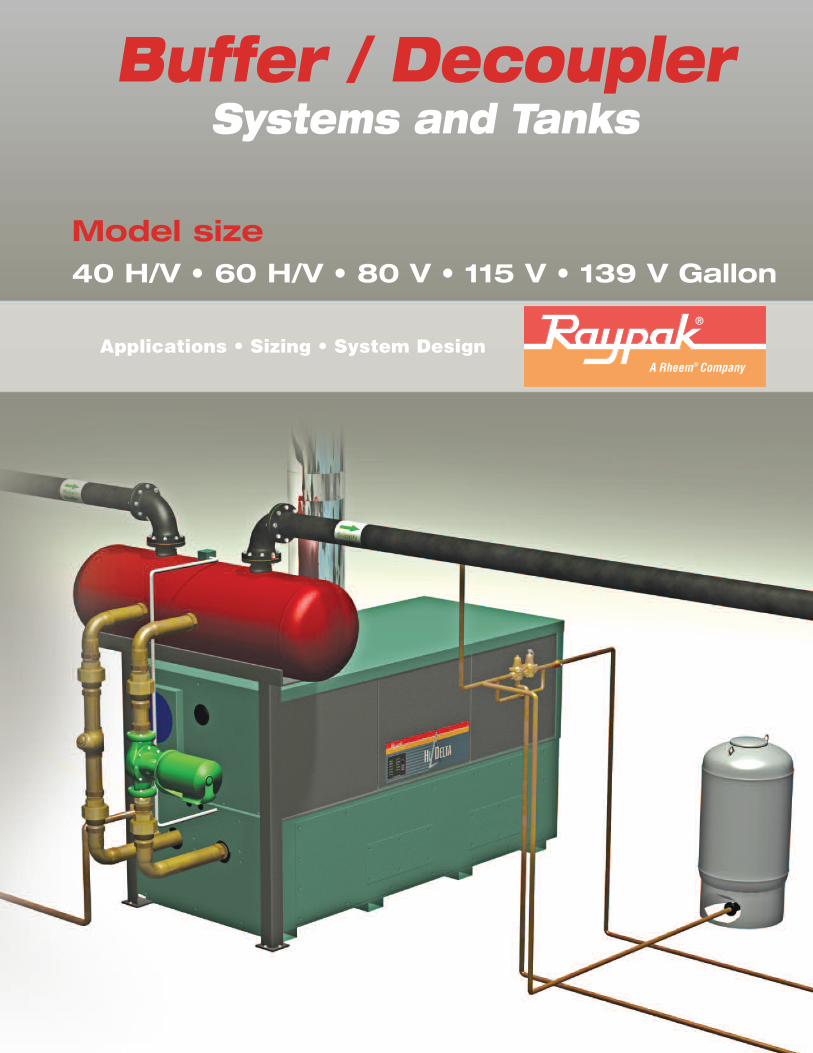
Model size40 H/V • 60 H/V • 80 V • 115 V • 139 V Gallon
Buffer / DecouplerSystems and Tanks
Applications • Sizing • System Design
2
Buffer / DecouplerSystems
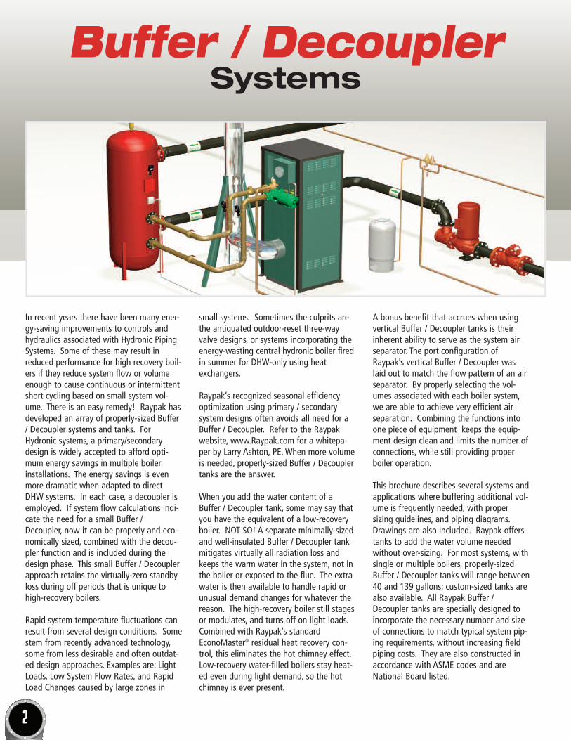
In recent years there have been many ener-gy-saving improvements to controls andhydraulics associated with Hydronic PipingSystems. Some of these may result inreduced performance for high recovery boil-ers if they reduce system flow or volumeenough to cause continuous or intermittentshort cycling based on small system vol-ume. There is an easy remedy! Raypak hasdeveloped an array of properly-sized Buffer/ Decoupler systems and tanks. ForHydronic systems, a primary/secondarydesign is widely accepted to afford opti-mum energy savings in multiple boilerinstallations. The energy savings is evenmore dramatic when adapted to directDHW systems. In each case, a decoupler isemployed. If system flow calculations indi-cate the need for a small Buffer /Decoupler, now it can be properly and eco-nomically sized, combined with the decou-pler function and is included during thedesign phase. This small Buffer / Decouplerapproach retains the virtually-zero standbyloss during off periods that is unique tohigh-recovery boilers.
Rapid system temperature fluctuations canresult from several design conditions. Somestem from recently advanced technology,some from less desirable and often outdat-ed design approaches. Examples are: LightLoads, Low System Flow Rates, and RapidLoad Changes caused by large zones in
small systems. Sometimes the culprits arethe antiquated outdoor-reset three-wayvalve designs, or systems incorporating theenergy-wasting central hydronic boiler firedin summer for DHW-only using heatexchangers.
Raypak’s recognized seasonal efficiencyoptimization using primary / secondary system designs often avoids all need for aBuffer / Decoupler. Refer to the Raypakwebsite, www.Raypak.com for a whitepa-per by Larry Ashton, PE. When more volumeis needed, properly-sized Buffer / Decouplertanks are the answer.
When you add the water content of aBuffer / Decoupler tank, some may say thatyou have the equivalent of a low-recoveryboiler. NOT SO! A separate minimally-sizedand well-insulated Buffer / Decoupler tankmitigates virtually all radiation loss andkeeps the warm water in the system, not inthe boiler or exposed to the flue. The extrawater is then available to handle rapid orunusual demand changes for whatever thereason. The high-recovery boiler still stagesor modulates, and turns off on light loads.Combined with Raypak’s standardEconoMaster® residual heat recovery con-trol, this eliminates the hot chimney effect.Low-recovery water-filled boilers stay heat-ed even during light demand, so the hotchimney is ever present.
A bonus benefit that accrues when usingvertical Buffer / Decoupler tanks is theirinherent ability to serve as the system airseparator. The port configuration ofRaypak’s vertical Buffer / Decoupler waslaid out to match the flow pattern of an airseparator. By properly selecting the vol-umes associated with each boiler system,we are able to achieve very efficient airseparation. Combining the functions intoone piece of equipment keeps the equip-ment design clean and limits the number ofconnections, while still providing properboiler operation.
This brochure describes several systems andapplications where buffering additional vol-ume is frequently needed, with proper sizing guidelines, and piping diagrams.Drawings are also included. Raypak offerstanks to add the water volume neededwithout over-sizing. For most systems, withsingle or multiple boilers, properly-sizedBuffer / Decoupler tanks will range between40 and 139 gallons; custom-sized tanks arealso available. All Raypak Buffer /Decoupler tanks are specially designed toincorporate the necessary number and sizeof connections to match typical system pip-ing requirements, without increasing fieldpiping costs. They are also constructed inaccordance with ASME codes and areNational Board listed.
3
Buffer / DecouplerSizing
Buffer / Decoupler - WhenNeeded?
• Any time reduced system volume can cause short-cycling.
• Multi-zone system can reduce flow and available volume to the boiler.
• Main circulator with a VFD often reduces system flow below boiler flow rate.
• Three-way valves utilized to achieve outdoor reset.
• VFD’s and/or 2-way zone valves can reduce system flow and available water volume below boiler minimum.
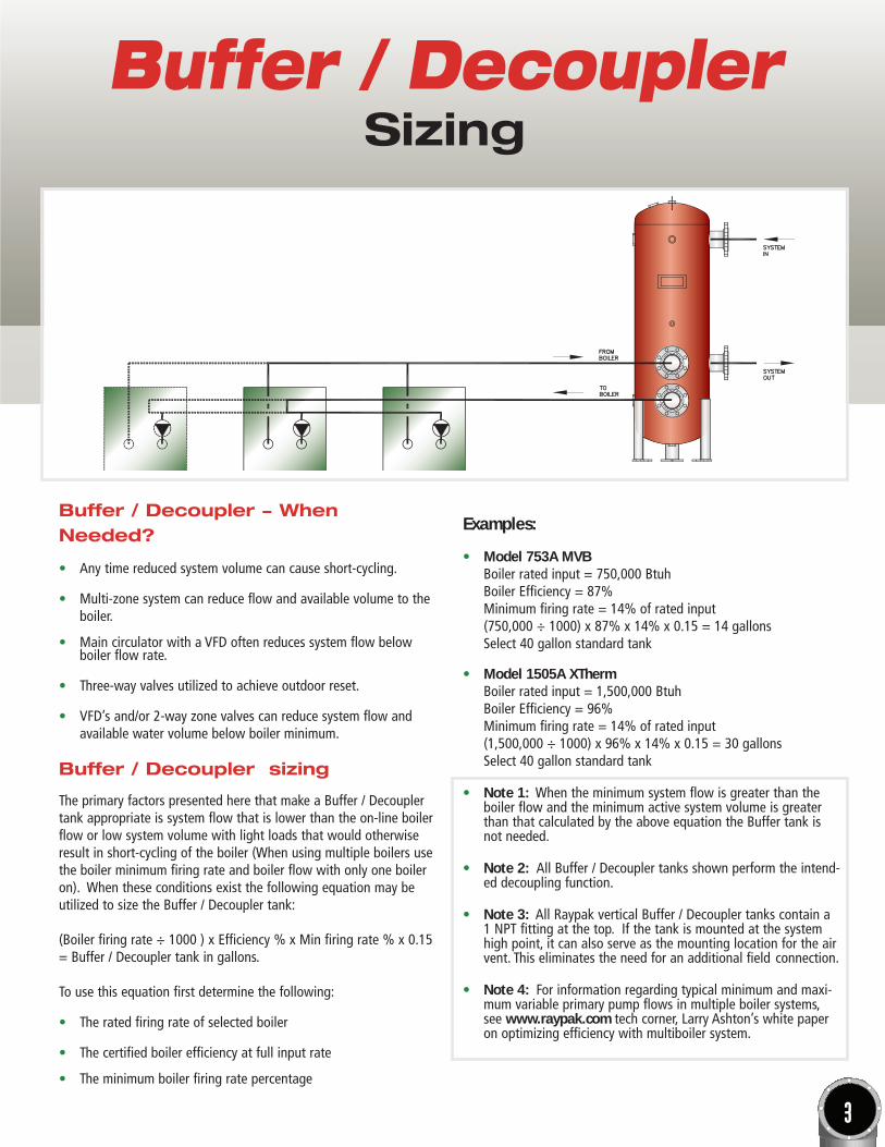
Buffer / Decoupler sizing
The primary factors presented here that make a Buffer / Decouplertank appropriate is system flow that is lower than the on-line boilerflow or low system volume with light loads that would otherwiseresult in short-cycling of the boiler (When using multiple boilers usethe boiler minimum firing rate and boiler flow with only one boileron). When these conditions exist the following equation may beutilized to size the Buffer / Decoupler tank:
(Boiler firing rate ÷ 1000 ) x Efficiency % x Min firing rate % x 0.15= Buffer / Decoupler tank in gallons.
To use this equation first determine the following:
• The rated firing rate of selected boiler
• The certified boiler efficiency at full input rate
• The minimum boiler firing rate percentage
Examples:
• Model 753A MVBBoiler rated input = 750,000 BtuhBoiler Efficiency = 87%Minimum firing rate = 14% of rated input(750,000 ÷ 1000) x 87% x 14% x 0.15 = 14 gallonsSelect 40 gallon standard tank
• Model 1505A XThermBoiler rated input = 1,500,000 BtuhBoiler Efficiency = 96%Minimum firing rate = 14% of rated input (1,500,000 ÷ 1000) x 96% x 14% x 0.15 = 30 gallonsSelect 40 gallon standard tank
• Note 1: When the minimum system flow is greater than the boiler flow and the minimum active system volume is greater than that calculated by the above equation the Buffer tank is not needed.
• Note 2: All Buffer / Decoupler tanks shown perform the intend-ed decoupling function.
• Note 3: All Raypak vertical Buffer / Decoupler tanks contain a1 NPT fitting at the top. If the tank is mounted at the system high point, it can also serve as the mounting location for the air vent. This eliminates the need for an additional field connection.
• Note 4: For information regarding typical minimum and maxi-mum variable primary pump flows in multiple boiler systems, see www.raypak.com tech corner, Larry Ashton’s white paper on optimizing efficiency with multiboiler system.
4
1 NPTGAUGE
1/2 NPT
TO BOILER(4X) 2-1/2 NPT
1 NPTDRAIN
2 NPT w/PLUGINSPECTION OPENING
121
1
“± 38
“ TYP.
“
“
4
58
2 “ TYP.
10
“4
50 34
316”
(2X) BAFFLE
17 14 “
w/STANDOFFASME NAMEPLATE
FROM SYSTEM(BAFFLED)
TO SYSTEM
1/2 NPTSENSOR WELL
FROM BOILER(BAFFLED)
49 78 “± 3
8 “
5”
w/STANDOFFASME NAMEPLATE
(2X) BAFFLE
20”
3 “10 4
21 14 “
(2X) 1 NPTDRAIN
INSPECTION OPENING
1/2 NPTSENSOR WELL
(2X) 2 NPT w/PLUG
TO BOILER(4X) 2-1/2 NPT
2
24”
12”
1 “ TYP.
34
FROM SYSTEM(BAFFLED)
“
TYP.
FROM BOILER(BAFFLED)
GAUGE TO SYSTEM
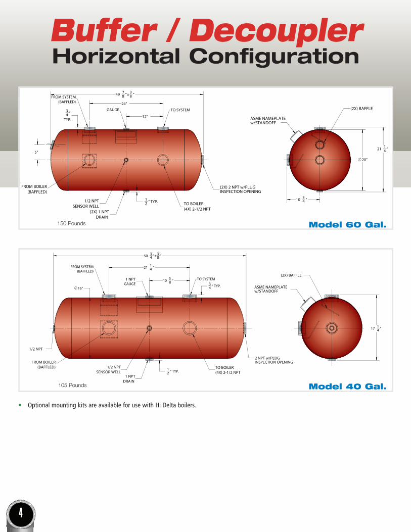
Model 40 Gal.
Model 60 Gal.150 Pounds
105 Pounds
Buffer / DecouplerHorizontal Configuration
• Optional mounting kits are available for use with Hi Delta boilers.
5
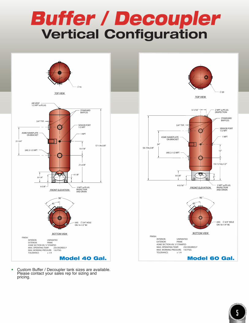
Buffer / DecouplerVertical Configuration
20
(4X)ON 18-1/4” BC
3/4” HOLE
SENSOR PORT1/2 NPT
2 NPT w/PLUG(INSPECTION
ASME NAMEPLATEON BRACKET
2 NPT w/PLUGINSPECTIONAND DRAIN
12”
4-5/16”
8-5/8”
1 NPT
5-1/16”
3/4” TYP.
(4X) 2-1/2 NPT
BOTTOM VIEW
TOP VIEW
FRONT ELEVATION
FINISH: INTERIOR: UNPAINTED EXTERIOR: PRIME ASME SECTION VIII, ‘U’ STAMPED MAX. OPERATING TEMP: 250 DEGREES F MAX. WORKING PRESSURE: 150 PSIG TOLERANCE: ± 1/4
90
45
24”
56-7/8±3/8”
6”
STANDARDBAFFLES
19-11/16±1/2”
Model 60 Gal.
16
BOTTOM VIEW
(4X)ON 14-1/2” BC
3/4” HOLE
SENSOR PORT1/2 NPT
STANDARDBAFFLES
ASME NAMEPLATEON BRACKET
3/4” TYP.
AIR VENT1/2 NPT w/PLUG
2 NPT w/PLUGINSPECTIONAND DRAIN
10-7/8”
4-1/8”
6-5/8”
8-1/4”
1 NPT
(4X) 2-1/2 NPT
TOP VIEW
FRONT ELEVATION
FINISH: INTERIOR: UNPAINTED EXTERIOR: PRIME ASME SECTION VIII, ‘U’ STAMPED MAX. OPERATING TEMP: 250 DEGREES F MAX. WORKING PRESSURE: 150 PSIG TOLERANCE: ± 1/4
90
45
21-3/4”
57-1/8±3/8”
21±3/8”
Model 40 Gal.
• Custom Buffer / Decoupler tank sizes are available.Please contact your sales rep for sizing and pricing.
6
Buffer / DecouplerVertical Configuration
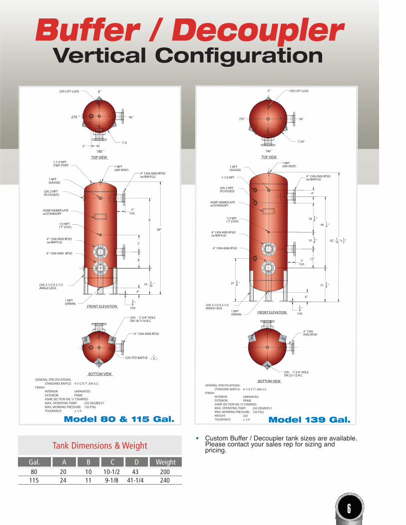
GENERAL SPECIFICATIONS: STANDARD BAFFLE: 4-1/2 X 7”, 304 S.S.FINISH: INTERIOR: UNPAINTED EXTERIOR: PRIME ASME SECTION VIII, ‘U’ STAMPED MAX. OPERATING TEMP: 250 DEGREES F MAX. WORKING PRESSURE: 150 PSIG WEIGHT: 325 TOLERANCE: ± 1/4
18 58 “
4”
45 14 “
27 38 “
(AIR VENT)1 NPT
1 NPT
ANGLE LEGS
4” 150# ANSI RFSO
(GAUGE)
(3X) 2-1/2 X 2-1/2
(w/BAFFLE)
1/2 NPT
(w/BAFFLE)
(’T’ STAT)
w/STANDOFF
1-1/2 NPT
ASME NAMEPLATE
(DRAIN)1 NPT
(PLUGGED)(2X) 2 NPT
4” 150# ANSI RFSO
4” 150# ANSI RFSO
10 1
12”
“
5
8
168
21 3
2“ “± ”
6”
82 1
38 “
TYP.
5”TYP.
FRONT ELEVATION
TOP VIEW
90
180
0 (2X) LIFT LUGS
270
24”
ON 22-1/2 B.C.3/4” HOLE(3X)
4” 150#ANSI RFSO
BOTTOM VIEW
Model 139 Gal.
D
90
0(2X) LIFT LUGS
270
A5”
(2X) STD BAFFLE
BOTTOM VIEW
ON 18-7/16 B.C.(3X) 3/4” HOLE
4” 150# ANSI RFSO
(3X) 2-1/2 X 2-1/2
(2X) 2 NPT
(GAUGE)
(PLUGGED)
1 NPT
1-1/2 NPT
(w/BAFFLE)
(T&P) PORT
4” 150# ANSI RFSO
4” 150# ANSI RFSO
w/STANDOFFASME NAMEPLATE
(’T’ STAT)1/2 NPT
(AIR VENT)1 NPT
(DRAIN)1 NPT
ANGLE LEGS
4” 150# ANSI RFSO(w/BAFFLE)
4”
C
3 “16
TYP.5”
B
16
69”
38 “
TYP.
TOP VIEW
FRONT ELEVATION
180
4
GENERAL SPECIFICATIONS: STANDARD BAFFLE: 4-1/2 X 7”, 304 S.S.FINISH: INTERIOR: UNPAINTED EXTERIOR: PRIME ASME SECTION VIII, ‘U’ STAMPED MAX. OPERATING TEMP: 250 DEGREES F MAX. WORKING PRESSURE: 150 PSIG TOLERANCE: ± 1/4
80 20 10 10-1/2 43 200 115 24 11 9-1/8 41-1/4 240
Tank Dimensions & Weight
A C DB Weight
Model 80 & 115 Gal.
Gal.
• Custom Buffer / Decoupler tank sizes are available.Please contact your sales rep for sizing and pricing.
7
Buffer / DecouplerApplications
FILLWATER
EXPANSIONTANK
WATERPRESSUREREGULATOR
BUFFERTANK
SYSTEMWATERSENSOR
THERMOMETER
AIR VENT
ZONE 3
ZONE 2
ZONE 1
SYSTEM PUMP
SYSTEMSUPPLY
ISOLATIONVAVLE (TYP)
SYSTEMRETURN
BOILER-MOUNTED PRESSURERELIEF VALVE
PUMP LOCATIONON MODELSWITHOUTINTEGRAL PUMP
OPTIONAL INTEGRAL PUMP(CERTAIN MODELS)
BUFFERTANK
FILLWATER
EXPANSIONTANK
SYSTEMWATERSENSOR
WATERPRESSUREREGULATOR
THERMOMETER
AIR VENT
ISOLATIONVALVE (TYP) SYSTEM
RETURN
SYSTEMSUPPLY
SYSTEM PUMP
ZONE 1
ZONE 2
BOILER-MOUNTEDPRESSURERELIEF VALVE
OPTIONAL INTEGRAL PUMP(CERTAIN MODELS)
PUMP LOCATIONON MODELSWITHOUTINTEGRAL PUMP
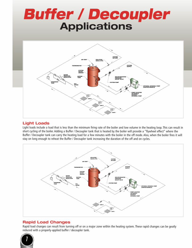
Light LoadsLight loads include a load that is less than the minimum firing rate of the boiler and low volume in the heating loop. This can result inshort cycling of the boiler. Adding a Buffer / Decoupler tank that is heated by the boiler will provide a “flywheel effect” where theBuffer / Decoupler tank can carry the heating load for a few minutes with the boiler in the off mode. Also, when the boiler fires it willstay on long enough to reheat the Buffer / Decoupler tank increasing the duration of the off and on cycles.
Rapid Load ChangesRapid load changes can result from turning off or on a major zone within the heating system. These rapid changes can be geatlyreduced with a properly-applied buffer / decoupler tank.
FILLWATER
THERMOMETER
SYSTEMWATERSENSOR
BUFFERTANK
AIR VENT
EXPANSIONTANK
SYSTEMRETURN
WATERPRESSUREREGULATOR
3-WAYOUTDOORRESET VALVE
SYSTEM PUMP
SYSTEMSUPPLY
ISOLATIONVALVES (TYP)
BOILER-MOUNTEDPRESSURERELIEF VALVE
PUMP LOCATIONON MODELSWITHOUTINTEGRAL PUMP
OPTIONAL INTEGRAL PUMP(CERTAIN MODELS)
FILLWATER
ZONE 2
ZONE 1
ZONE 3
ZONE 4
ZONE 5
ZONE 6
ZONE 7
ZONE 8
ZONE 9
ZONE 10
BUFFERTANK
SYSTEM PUMPEXPANSIONTANK
THERMOMETER
AIR VENT
SYSTEMWATERSENSOR
WATERPRESSUREREGULATOR
ISOLATIONVALVE (TYP)
SYSTEMRETURN
SYSTEMSUPPLY
BOILER-MOUNTEDPRESSURERELIEF VALVE
OPTIONAL INTEGRAL PUMP(CERTAIN MODELS)
PUMP LOCATIONON MODELSWITHOUTINTEGRAL PUMP
8
Buffer / DecouplerApplications
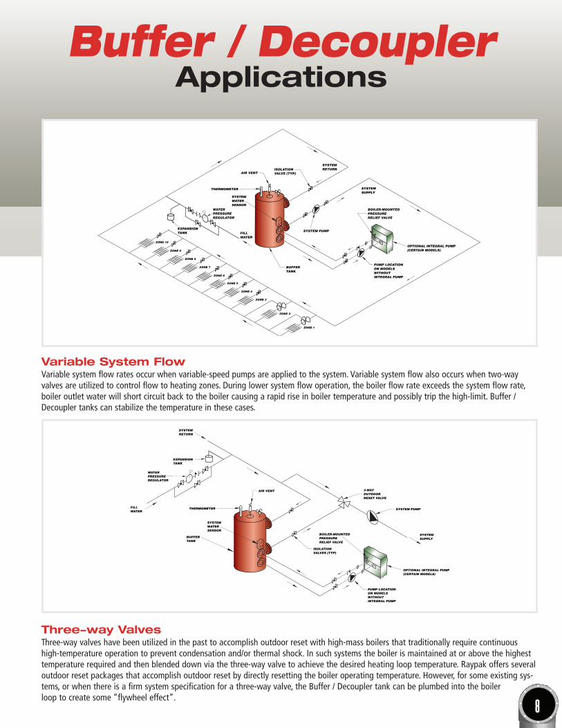
Three-way Valves Three-way valves have been utilized in the past to accomplish outdoor reset with high-mass boilers that traditionally require continuoushigh-temperature operation to prevent condensation and/or thermal shock. In such systems the boiler is maintained at or above the highesttemperature required and then blended down via the three-way valve to achieve the desired heating loop temperature. Raypak offers severaloutdoor reset packages that accomplish outdoor reset by directly resetting the boiler operating temperature. However, for some existing sys-tems, or when there is a firm system specification for a three-way valve, the Buffer / Decoupler tank can be plumbed into the boiler loop to create some “flywheel effect”.
Variable System FlowVariable system flow rates occur when variable-speed pumps are applied to the system. Variable system flow also occurs when two-wayvalves are utilized to control flow to heating zones. During lower system flow operation, the boiler flow rate exceeds the system flow rate,boiler outlet water will short circuit back to the boiler causing a rapid rise in boiler temperature and possibly trip the high-limit. Buffer /Decoupler tanks can stabilize the temperature in these cases.
9
Buffer / DecouplerApplications
BUFFERTANK
SYSTEMWATERSENSOR
THERMOMETER
AIR VENT
ISOLATIONVALVE (TYP)
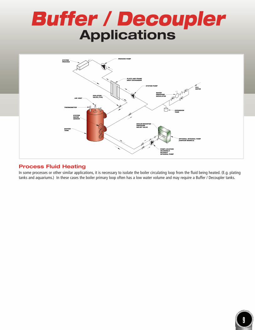
SYSTEMPROCESS
PROCESS PUMP
PLATE AND FRAMEHEAT EXCHANGER
SYSTEM PUMP
WATERPRESSUREREGULATOR
EXPANSIONTANK
FILLWATER
BOILER-MOUNTEDPRESSURERELIEF VALVE
OPTIONAL INTEGRAL PUMP(CERTAIN MODELS)
PUMP LOCATIONON MODELSWITHOUTINTEGRAL PUMP
Process Fluid HeatingIn some processes or other similar applications, it is necessary to isolate the boiler circulating loop from the fluid being heated. (E.g. platingtanks and aquariums.) In these cases the boiler primary loop often has a low water volume and may require a Buffer / Decoupler tanks.
Raypak, Inc. • 2151 Eastman Avenue, Oxnard, CA 93030 • phone: (805) 278-5300 • fax: (800) 872-8725 • www.raypak.com© 2011 Raypak, Inc. Cat. No. 2000.82-G Effective: 11-01-16 Replaces: 03-01-15
Buffer / DecouplerApplications
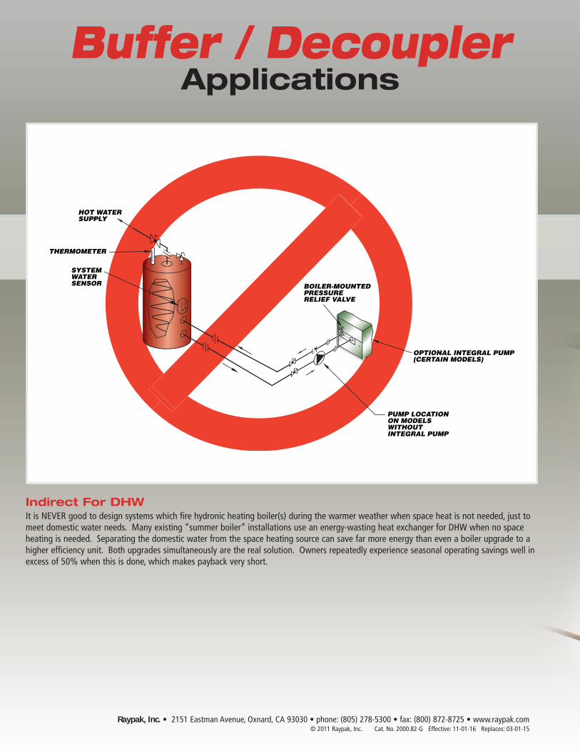
THERMOMETER
HOT WATERSUPPLY
SYSTEMWATERSENSOR
PUMP LOCATIONON MODELSWITHOUTINTEGRAL PUMP
OPTIONAL INTEGRAL PUMP(CERTAIN MODELS)
BOILER-MOUNTEDPRESSURERELIEF VALVE
Indirect For DHWIt is NEVER good to design systems which fire hydronic heating boiler(s) during the warmer weather when space heat is not needed, just tomeet domestic water needs. Many existing “summer boiler” installations use an energy-wasting heat exchanger for DHW when no spaceheating is needed. Separating the domestic water from the space heating source can save far more energy than even a boiler upgrade to ahigher efficiency unit. Both upgrades simultaneously are the real solution. Owners repeatedly experience seasonal operating savings well inexcess of 50% when this is done, which makes payback very short.