Embed Size (px)
Citation preview

Welcome.Thank you for buying anIBM server.
This servercontains information for settingup and configuring your server.
For detailed informationabout your server, view the
on the
You can also find the mostcurrent information about yourserver on the IBM Web site athttp://www.ibm.com/systems/x/.
Installation Guide
User's GuideDocumentation CD.
Installation Guide
System x3200 M2Types 4367 and 4368
Turn off the serverand install options.
Did the serverstart correctly?
Yes
No
Go to the Server Supportflow chart on the reverse
side of this page.
Start the server.
Did the serverstart correctly?
Yes
No
Cable the server and options;then, restart the server.
Was theserver setupcompleted?
UseServerGuide to
install the operatingsystem?
The server is ready to use.Go to
to register the server.http://www.ibm.com/support/mysupport/
Go to the Web for instructions:http://www.ibm.com/systems/support/
No
Yes
Yes
No
Use the IBMServerGuide program
to set up andconfigure hardware.
Go to the Server Supportflow chart on the reverse
side of this page.
Install applications,such as IBM systemsmanagement softwareand IBM ServeRAIDprograms


System x3200 M2 Types 4367 and 4368
Installation Guide
���

Note:
Before using this information and the product it supports, read the general information in Appendix B,“Notices,” on page 75, and the Warranty and Support Information document on the IBM System xDocumentation CD.
Third Edition (September 2009)
© Copyright International Business Machines Corporation 2009.US Government Users Restricted Rights – Use, duplication or disclosure restricted by GSA ADP Schedule Contractwith IBM Corp.

Contents
Safety . . . . . . . . . . . . . . . . . . . . . . . . . . . . v
Chapter 1. Introduction . . . . . . . . . . . . . . . . . . . . . . 1The IBM System x Documentation CD. . . . . . . . . . . . . . . . . 4
Hardware and software requirements . . . . . . . . . . . . . . . . 4Using the Documentation Browser . . . . . . . . . . . . . . . . . 4
Notices and statements in this document . . . . . . . . . . . . . . . . 5Features and specifications . . . . . . . . . . . . . . . . . . . . . 6Major components of the server . . . . . . . . . . . . . . . . . . . 8
Chapter 2. Installing optional devices . . . . . . . . . . . . . . . . 9Installation guidelines . . . . . . . . . . . . . . . . . . . . . . . 9
System reliability guidelines . . . . . . . . . . . . . . . . . . . 10Working inside the server with the power on . . . . . . . . . . . . . 10Handling static-sensitive devices . . . . . . . . . . . . . . . . . 11
Removing the side cover . . . . . . . . . . . . . . . . . . . . . 12Removing the two-piece bezel . . . . . . . . . . . . . . . . . . . 13Installing a memory module . . . . . . . . . . . . . . . . . . . . 15Installing a drive . . . . . . . . . . . . . . . . . . . . . . . . 19
Installing a CD or DVD drive . . . . . . . . . . . . . . . . . . . 20Installing a tape drive . . . . . . . . . . . . . . . . . . . . . 22Installing a hot-swap SAS or hot-swap SATA hard disk drive . . . . . . . 23IDs for hot-swap hard disk drives . . . . . . . . . . . . . . . . . 25Installing a simple-swap SATA hard disk drive . . . . . . . . . . . . 26Power and signal cables for internal drives . . . . . . . . . . . . . 28
Installing an adapter . . . . . . . . . . . . . . . . . . . . . . . 28Completing the installation. . . . . . . . . . . . . . . . . . . . . 32
Reinstalling the two-piece bezel. . . . . . . . . . . . . . . . . . 32Reinstalling the side cover. . . . . . . . . . . . . . . . . . . . 34Connecting the cables . . . . . . . . . . . . . . . . . . . . . 35Updating the server configuration . . . . . . . . . . . . . . . . . 36
Chapter 3. Server controls, LEDs, and power. . . . . . . . . . . . . 37Front view . . . . . . . . . . . . . . . . . . . . . . . . . . 37Rear view . . . . . . . . . . . . . . . . . . . . . . . . . . . 39Server power features . . . . . . . . . . . . . . . . . . . . . . 40
Turning on the server . . . . . . . . . . . . . . . . . . . . . 40Turning off the server . . . . . . . . . . . . . . . . . . . . . 40
Chapter 4. Configuring the server . . . . . . . . . . . . . . . . . 43Using the ServerGuide Setup and Installation CD . . . . . . . . . . . . 43Using the Configuration/Setup Utility program . . . . . . . . . . . . . 44Using the Boot Menu program . . . . . . . . . . . . . . . . . . . 44Enabling the Broadcom NetXtreme Gigabit Ethernet Boot Agent . . . . . . . 44Configuring the Broadcom NetXtreme Gigabit Ethernet controller . . . . . . 45LSI Configuration Utility program . . . . . . . . . . . . . . . . . . 45
Chapter 5. Solving problems . . . . . . . . . . . . . . . . . . . 47Diagnostic tools overview . . . . . . . . . . . . . . . . . . . . . 47POST beep codes . . . . . . . . . . . . . . . . . . . . . . . 47POST error codes. . . . . . . . . . . . . . . . . . . . . . . . 48Troubleshooting tables . . . . . . . . . . . . . . . . . . . . . . 58
CD or DVD drive problems . . . . . . . . . . . . . . . . . . . 59
© Copyright IBM Corp. 2009 iii

Diskette drive problems. . . . . . . . . . . . . . . . . . . . . 60General problems . . . . . . . . . . . . . . . . . . . . . . . 60Hard disk drive problems . . . . . . . . . . . . . . . . . . . . 60Intermittent problems. . . . . . . . . . . . . . . . . . . . . . 61Keyboard, mouse, or pointing-device problems . . . . . . . . . . . . 62Memory problems . . . . . . . . . . . . . . . . . . . . . . . 63Microprocessor problems . . . . . . . . . . . . . . . . . . . . 64Monitor problems . . . . . . . . . . . . . . . . . . . . . . . 64Optional-device problems . . . . . . . . . . . . . . . . . . . . 67Power problems . . . . . . . . . . . . . . . . . . . . . . . 68Serial-device problems . . . . . . . . . . . . . . . . . . . . . 69ServerGuide problems . . . . . . . . . . . . . . . . . . . . . 69Software problems . . . . . . . . . . . . . . . . . . . . . . 70Universal Serial Bus (USB) device problems . . . . . . . . . . . . . 71
System-board LEDs . . . . . . . . . . . . . . . . . . . . . . . 71
Appendix A. Getting help and technical assistance . . . . . . . . . . 73Before you call . . . . . . . . . . . . . . . . . . . . . . . . . 73Using the documentation . . . . . . . . . . . . . . . . . . . . . 73Getting help and information from the World Wide Web . . . . . . . . . . 73Software service and support . . . . . . . . . . . . . . . . . . . 74Hardware service and support . . . . . . . . . . . . . . . . . . . 74IBM Taiwan product service . . . . . . . . . . . . . . . . . . . . 74
Appendix B. Notices . . . . . . . . . . . . . . . . . . . . . . 75Trademarks . . . . . . . . . . . . . . . . . . . . . . . . . . 75Important notes. . . . . . . . . . . . . . . . . . . . . . . . . 76Particulate contamination . . . . . . . . . . . . . . . . . . . . . 77Documentation format . . . . . . . . . . . . . . . . . . . . . . 78Electronic emission notices . . . . . . . . . . . . . . . . . . . . 78
Federal Communications Commission (FCC) statement . . . . . . . . . 78Industry Canada Class A emission compliance statement . . . . . . . . 79Avis de conformité à la réglementation d’Industrie Canada . . . . . . . . 79Australia and New Zealand Class A statement . . . . . . . . . . . . 79United Kingdom telecommunications safety requirement. . . . . . . . . 79European Union EMC Directive conformance statement . . . . . . . . . 79Taiwanese Class A warning statement . . . . . . . . . . . . . . . 80Germany Electromagnetic Compatibility Directive . . . . . . . . . . . 80People's Republic of China Class A warning statement . . . . . . . . . 81Japanese Voluntary Control Council for Interference (VCCI) statement . . . 81Korean Class A warning statement . . . . . . . . . . . . . . . . 81
Index . . . . . . . . . . . . . . . . . . . . . . . . . . . . 83
iv System x3200 M2 Types 4367 and 4368: Installation Guide

Safety
Before installing this product, read the Safety Information.
Antes de instalar este produto, leia as Informações de Segurança.
Pred instalací tohoto produktu si prectete prírucku bezpecnostních instrukcí.
Læs sikkerhedsforskrifterne, før du installerer dette produkt.
Lees voordat u dit product installeert eerst de veiligheidsvoorschriften.
Ennen kuin asennat tämän tuotteen, lue turvaohjeet kohdasta Safety Information.
Avant d’installer ce produit, lisez les consignes de sécurité.
Vor der Installation dieses Produkts die Sicherheitshinweise lesen.
Prima di installare questo prodotto, leggere le Informazioni sulla Sicurezza.
Les sikkerhetsinformasjonen (Safety Information) før du installerer dette produktet.
Antes de instalar este produto, leia as Informações sobre Segurança.
Antes de instalar este producto, lea la información de seguridad.
Läs säkerhetsinformationen innan du installerar den här produkten.
© Copyright IBM Corp. 2009 v

Important:
Each caution and danger statement in this document is labeled with anumber. This number is used to cross reference an English-languagecaution or danger statement with translated versions of the caution ordanger statement in the Safety Information document.
For example, if a caution statement is labeled “Statement 1,”translations for that caution statement are in the IBM Safety Informationdocument under “Statement 1.”
Be sure to read all caution and danger statements in this documentbefore you perform the procedures. Read any additional safetyinformation that comes with the server or optional device before youinstall the device.
vi System x3200 M2 Types 4367 and 4368: Installation Guide

Statement 1:
DANGER
Electrical current from power, telephone, and communication cables ishazardous.
To avoid a shock hazard:
v Do not connect or disconnect any cables or perform installation,maintenance, or reconfiguration of this product during an electricalstorm.
v Connect all power cords to a properly wired and grounded electricaloutlet.
v Connect to properly wired outlets any equipment that will be attached tothis product.
v When possible, use one hand only to connect or disconnect signalcables.
v Never turn on any equipment when there is evidence of fire, water, orstructural damage.
v Disconnect the attached power cords, telecommunications systems,networks, and modems before you open the device covers, unlessinstructed otherwise in the installation and configuration procedures.
v Connect and disconnect cables as described in the following table wheninstalling, moving, or opening covers on this product or attacheddevices.
To Connect: To Disconnect:
1. Turn everything OFF.
2. First, attach all cables to devices.
3. Attach signal cables to connectors.
4. Attach power cords to outlet.
5. Turn device ON.
1. Turn everything OFF.
2. First, remove power cords from outlet.
3. Remove signal cables from connectors.
4. Remove all cables from devices.
Safety vii

Statement 2:
CAUTION:When replacing the lithium battery, use only IBM Part Number 33F8354 or anequivalent type battery recommended by the manufacturer. If your system hasa module containing a lithium battery, replace it only with the same moduletype made by the same manufacturer. The battery contains lithium and canexplode if not properly used, handled, or disposed of.
Do not:
v Throw or immerse into water
v Heat to more than 100°C (212°F)
v Repair or disassemble
Dispose of the battery as required by local ordinances or regulations.
viii System x3200 M2 Types 4367 and 4368: Installation Guide

Statement 3:
CAUTION:When laser products (such as CD-ROMs, DVD drives, fiber optic devices, ortransmitters) are installed, note the following:
v Do not remove the covers. Removing the covers of the laser product couldresult in exposure to hazardous laser radiation. There are no serviceableparts inside the device.
v Use of controls or adjustments or performance of procedures other thanthose specified herein might result in hazardous radiation exposure.
DANGER
Some laser products contain an embedded Class 3A or Class 3B laserdiode. Note the following.
Laser radiation when open. Do not stare into the beam, do not view directlywith optical instruments, and avoid direct exposure to the beam.
Class 1 Laser ProductLaser Klasse 1Laser Klass 1Luokan 1 LaserlaiteAppareil A Laser de Classe 1`
Safety ix

Statement 4:
≥ 18 kg (39.7 lb) ≥ 32 kg (70.5 lb) ≥ 55 kg (121.2 lb)
CAUTION:Use safe practices when lifting.
Statement 5:
CAUTION:The power control button on the device and the power switch on the powersupply do not turn off the electrical current supplied to the device. The devicealso might have more than one power cord. To remove all electrical currentfrom the device, ensure that all power cords are disconnected from the powersource.
1
2
x System x3200 M2 Types 4367 and 4368: Installation Guide

Statement 8:
CAUTION:Never remove the cover on a power supply or any part that has the followinglabel attached.
Hazardous voltage, current, and energy levels are present inside anycomponent that has this label attached. There are no serviceable parts insidethese components. If you suspect a problem with one of these parts, contacta service technician.
Statement 12:
CAUTION:The following label indicates a hot surface nearby.
Statement 13:
DANGER
Overloading a branch circuit is potentially a fire hazard and a shock hazardunder certain conditions. To avoid these hazards, ensure that your systemelectrical requirements do not exceed branch circuit protectionrequirements. Refer to the information that is provided with your device forelectrical specifications.
Safety xi

Statement 15:
CAUTION:Make sure that the rack is secured properly to avoid tipping when the serverunit is extended.
xii System x3200 M2 Types 4367 and 4368: Installation Guide

Chapter 1. Introduction
This Installation Guide contains instructions for setting up the IBM System x3200M2 Machine Types 4367 and 4368 server and basic instructions for installing someoptional devices. More detailed instructions for installing optional devices are in theUser’s Guide on the IBM System x® Documentation CD, which comes with theserver. This document contains information about:
v Setting up and cabling the server
v Starting and configuring the server
v Installing some optional devices
v Solving problems
If firmware and documentation updates are available, you can download them fromthe IBM Web site. The server might have features that are not described in thedocumentation that comes with the server, and the documentation might be updatedoccasionally to include information about those features, or technical updates mightbe available to provide additional information that is not included in the serverdocumentation. To check for updates, complete the following steps.
Note: Changes are made periodically to the IBM Web site. Procedures for locatingfirmware and documentation might vary slightly from what is described in thisdocument.
1. Go to http://www.ibm.com/systems/support/.
2. Under Product support, click System x.
3. Under Popular links, click Software and device drivers for firmware updates,or click Publications lookup for documentation updates.
The server comes with an IBM ServerGuide Setup and Installation CD to help youconfigure the hardware, install device drivers, and install the operating system.
The server comes with a limited warranty. You can obtain up-to-date informationabout the server and other IBM server products at http://www.ibm.com/systems/x/.
Record information about the server in the following table. You will need thisinformation when you register the server with IBM.
Product name IBM System x3200 M2Machine type 4367 or 4368Model number _____________________________________________Serial number _____________________________________________Key serial number _____________________________________________Key manufacturer _____________________________________________Key phone number _____________________________________________
© Copyright IBM Corp. 2009 1

The model number and serial number are on the lower-right side of the bezel, asshown in the following illustrations. This illustration might differ slightly from yourhardware.
Note: This illustration shows a hot-swap model. A non-hot-swap hard disk drivemodel is also available.
Model numberand serial number
2 System x3200 M2 Types 4367 and 4368: Installation Guide

Important: The server keys cannot be duplicated by a locksmith. If you lose them,order replacement keys from the key manufacturer. The key serialnumber and the telephone number of the manufacturer are on a tagthat is attached to the keys.
The server keys are in a plastic bag and attached to the front of the server chassisbehind the lower-bezel door. To access the keys, remove the lower-bezel. Thefollowing illustration shows the location on the server where you can find the keys:
Keys
If you plan to install the server in a rack, you must purchase a Tower-to-Rack Kit.For a list of supported optional devices for the server, see http://www.ibm.com/servers/eserver/serverproven/compat/us/.
Chapter 1. Introduction 3

The IBM System x Documentation CDThe IBM System x Documentation CD contains documentation for the server inPortable Document Format (PDF) and includes the IBM Documentation Browser tohelp you find information quickly.
Hardware and software requirementsThe IBM System x Documentation CD requires the following minimum hardwareand software:
v Microsoft Windows XP, Windows 2000, or Red Hat Linux
v 100 MHz microprocessor
v 32 MB of RAM
v Adobe Acrobat Reader 3.0 (or later) or xpdf, which comes with Linux operatingsystems
Using the Documentation BrowserUse the Documentation Browser to browse the contents of the CD, read briefdescriptions of the documents, and view documents using Adobe Acrobat Reader orxpdf. The Documentation Browser automatically detects the regional settings in usein your server and displays the documents in the language for that region (ifavailable). If a document is not available in the language for that region, theEnglish-language version is displayed.
Use one of the following procedures to start the Documentation Browser:
v If Autostart is enabled, insert the CD into the CD or DVD drive. TheDocumentation Browser starts automatically.
v If Autostart is disabled or is not enabled for all users, use one of the followingprocedures:
– If you are using a Windows operating system, insert the CD into the CD orDVD drive and click Start --> Run. In the Open field, typee:\win32.bat
where e is the drive letter of the CD or DVD drive, and click OK.
– If you are using Red Hat Linux, insert the CD into the CD or DVD ndrive;then, run the following command from the /mnt/cdrom directory:sh runlinux.sh
Select your server from the Product menu. The Available Topics list displays allthe documents for your server. Some documents might be in folders. A plus sign (+)indicates each folder or document that has additional documents under it. Click theplus sign to display the additional documents.
When you select a document, a description of the document is displayed underTopic Description. To select more than one document, press and hold the Ctrl keywhile you select the documents. Click View Book to view the selected document ordocuments in Acrobat Reader or xpdf. If you selected more than one document, allthe selected documents are opened in Acrobat Reader or xpdf.
To search all the documents, type a word or word string in the Search field andclick Search. The documents in which the word or word string appears are listed inorder of the most occurrences. Click a document to view it, and press Crtl+F to usethe Acrobat search function, or press Alt+F to use the xpdf search function withinthe document.
4 System x3200 M2 Types 4367 and 4368: Installation Guide

Click Help for detailed information about using the Documentation Browser.
Notices and statements in this documentThe caution and danger statements in this document are also in the multilingualSafety Information document, which is on the IBM System x Documentation CD.Each statement is numbered for reference to the corresponding statement in theSafety Information document.
The following notices and statements are used in this document:
v Note: These notices provide important tips, guidance, or advice.
v Important: These notices provide information or advice that might help you avoidinconvenient or problem situations.
v Attention: These notices indicate potential damage to programs, devices, ordata. An attention notice is placed just before the instruction or situation in whichdamage might occur.
v Caution: These statements indicate situations that can be potentially hazardousto you. A caution statement is placed just before the description of a potentiallyhazardous procedure step or situation.
v Danger: These statements indicate situations that can be potentially lethal orextremely hazardous to you. A danger statement is placed just before thedescription of a potentially lethal or extremely hazardous procedure step orsituation.
Chapter 1. Introduction 5

Features and specificationsThe following information is a summary of the features and specifications of theserver. Depending on the server model, some features might not be available, orsome specifications might not apply.
6 System x3200 M2 Types 4367 and 4368: Installation Guide

Table 1. Features and specifications
Microprocessor:v Supports one Intel® Core™ 2 Duo
dual-core or Xeon® dual-core orquad-core microprocessorNote: Intel Virtualization Technology(VT) is not available on the Core 2Duo E4600; however, thesemicroprocessors can only runparavirtualization.
v 2 MB, 6 MB, or 12 MB Level-2 cachev 800, 1066, or 1333 MHz front-side
bus (FSB)
Memory:v Minimum: 512 MBv Maximum: 8 GBv Types: PC2-5300 or PC2-6400, ECC
unbuffered double-data-rate 2(DDR2) 667 or 800 MHz SDRAM
v Connectors: four dual inline memorymodule (DIMM) connectors, two-wayinterleaved
Drives (depending on the model):v Diskette (optional): External or
internal USB FDD drive and memorykey
v Hard disk drive: Hot-swap SAS,hot-swap SATA, or simple-swapSATA
v One of the following SATA attachedoptical drives:– DVD-ROM– Multiburner (optional)
Drive bays (depending on themodel):v Two 5.25 in. half-high bays (one
optical drive installed)v One 3.5 in. slim-high
removable-media drive bay (optionaldiskette drive)
v Four 3.5 in. or 2.5 in. slim-high harddisk drive bays (some models)
v Eight 2.5 in. slim-high hard disk drivebays (some models)
PCI expansion slots (depending onthe model):
v One PCI Express x8 slot
v One PCI Express x4 slot (x4 slot withx1 electrical)
v One PCI-X 64-bit/133 MHz slotNote: This PCI-X slot is enabledwhen an optional PCI-X enablementcard is installed in the mini-PCI sloton the system board. When nomini-PCI-X enablement card installed,this slot has no function.
v Two PCI 32-bit/33 MHz slots
Fans:Three speed-controlled fans.
Power supply:One of the following power supplies:
v One or two redundant 430-watt (90-240V ac)
v One non-redundant 401-watt (90-240 Vac)
Size:v Height: 438 mm (17.25 in.)v Depth: 540 mm (21.25 in.)v Width: 216 mm (8.5 in.)v Weight: 16.3 kg (36 lb) to 25.2 kg (56
lb) depending upon configuration
Integrated functions:v Mini-baseboard management controller
(mini-BMC)v Broadcom BCM5722 10/100/1000
Ethernet controller on the system boardwith RJ-45 Ethernet port
v One internal single-channnel (four portsper channel) SAS/SATA controller(mini-PCI slot)
v Two serial portsv One parallel portv Six-port Serial ATA controllerv Eight Universal Serial Bus (USB) v2.0
ports (two on front and four on rear, oneinternal for optional tape drive, and oneinternal for optional Remote SupervisorAdapter II SlimLine)
v Onboard ATI ES1000 video controller– Compatible with SVGA and VGA– 64 MB DDR2 SDRAM video memory
Diagnostic LEDs:v Fansv Hard disk drivesv Memoryv Microprocessorv PCI slotsv Power supplyv VRD
Acoustical noise emissions:v Sound power, idling: 5.0 belv Sound power, operating: 5.3 bel
Environment:v Air temperature:
– Server on: 10° to 35°C (50° to 95°F)Altitude: 0 to 914.4 m (3000 ft)
– Server on: 10° to 32°C (50° to 89.6°F)Altitude: 914.4 m (3000 ft) to 2133.6 m(7000 ft)
– Server off: 10° to 43°C (50° to 109.4°F)Maximum altitude: 2133.6 m (7000 ft)
– Shipping: -40° to 60°C (-40° to 140°F)v Humidity (operating and storage):
– Server on: 8% to 80%– Server off: 8% to 80%
v Particulate contamination:
Attention: Airborne particulates andreactive gases acting alone or incombination with other environmentalfactors such as humidity or temperaturemight pose a risk to the server. Forinformation about the limits for particulatesand gases, see “Particulate contamination”on page 77.
Heat output:Approximate heat output in British thermalunits (Btu) per hour:v Minimum configuration: 630 Btu per hour
(185 watts)v Maximum configuration: 1784 Btu per hour
(523 watts)
Electrical input:v Sine-wave input (50 or 60 Hz) requiredv Input voltage and frequency ranges
automatically selectedv Input voltage low range:
– Minimum: 100 V ac– Maximum: 127 V ac
v Input voltage high range:– Minimum: 200 V ac– Maximum: 240 V ac
v Input kilovolt-amperes (kVA) approximately:– Minimum: 0.20 kVA (all models)– Maximum: 0.55 kVA
Notes:
1. Power consumption and heat output varydepending on the number and type ofoptional features that are installed and thepower-management optional features thatare in use.
2. These levels were measured in controlledacoustical environments according to theprocedures specified by the AmericanNational Standards Institute (ANSI) S12.10and ISO 7779 and are reported inaccordance with ISO 9296. Actualsound-pressure levels in a given locationmight exceed the average stated valuesbecause of room reflections and othernearby noise sources. The declaredsound-power levels indicate an upper limit,below which a large number of computerswill operate.
Chapter 1. Introduction 7

Major components of the serverBlue on a component indicates touch points, where you can grip the component toremove it from or install it in the server, open or close a latch, and so on.
Orange on a component or an orange label on or near a component indicates thatthe component can be hot-swapped, which means that if the server and operatingsystem support hot-swap capability, you can remove or install the component whilethe server is running. (Orange can also indicate touch points on hot-swapcomponents.) See the instructions for removing or installing a specific hot-swapcomponent for any additional procedures that you might have to perform before youremove or install the component.
The following illustration shows the major components in the server.
Note: The illustrations in this document might differ slightly from your hardware.
Front adapter-support bracket
Drive cage
EMC shields
Fillerpanels
Cover
System board
Upperbezel
Lowerbezel
Microprocessor
Heat sink
Non-hot-swappower supply
Hot-swappower supply
DIMM
SAS/SATA controller
SATAhard disk drive(some models)
Hot-swaphard disk drive(some models)
SATA filler panel
SAS filler panel
Rear system fan
Optical drive
Hard disk drivefan assembly
Diskette drive(optional)
8 System x3200 M2 Types 4367 and 4368: Installation Guide

Chapter 2. Installing optional devices
This chapter provides basic instructions for installing optional hardware devices inthe server. These instructions are intended for users who are experienced withsetting up IBM server hardware. If you need more detailed instructions, see theUser’s Guide on the IBM System x Documentation CD.
Installation guidelinesBefore you install optional devices, read the following information:
v Read the safety information that begins on page v, the guidelines in “Workinginside the server with the power on” on page 10, and “Handling static-sensitivedevices” on page 11. This information will help you work safely.
v Observe good housekeeping in the area where you are working. Place removedcovers and other parts in a safe place.
v When you install your new server, take the opportunity to download and applythe most recent firmware updates. This step will help to ensure that any knownissues are addressed and that your server is ready to function at maximum levelsof performance. To download firmware updates for your server, complete thefollowing steps.
Note: Changes are made periodically to the IBM Web site. The actual proceduremight vary slightly from what is described in this document.
1. Go to http://www.ibm.com/systems/support/.
2. Under Product support, click System x.
3. Under Popular links, click Software and device drivers.
4. Click IBM System x3200 M2 to display the matrix of downloadable files forthe server.
For additional information about tools for updating, managing, and deployingfirmware, see the System x and xSeries Tools Center at http://publib.boulder.ibm.com/infocenter/toolsctr/v1r0/index.jsp.
v Before you install optional hardware devices, make sure that the server isworking correctly. Start the server, and make sure that the operating systemstarts, if an operating system is installed, or that a 19990305 error code isdisplayed, indicating that an operating system was not found but the server isotherwise working correctly. If the server is not working correctly, see Solvingproblems for diagnostic information.
v Observe good housekeeping in the area where you are working. Place removedcovers and other parts in a safe place.
v If you must start the server while the cover is removed, make sure that no one isnear the server and that no tools or other objects have been left inside theserver.
v Do not attempt to lift an object that you think is too heavy for you. If you have tolift a heavy object, observe the following precautions:
– Make sure that you can stand safely without slipping.
– Distribute the weight of the object equally between your feet.
– Use a slow lifting force. Never move suddenly or twist when you lift a heavyobject.
– To avoid straining the muscles in your back, lift by standing or by pushing upwith your leg muscles.
© Copyright IBM Corp. 2009 9

v Make sure that you have an adequate number of properly grounded electricaloutlets for the server, monitor, and other devices.
v Back up all important data before you make changes to disk drives.
v Have a small flat-blade screwdriver available.
v You do not have to turn off the server to install or replace hot-swap powersupplies or hot-plug Universal Serial Bus (USB) devices. However, you must turnoff the server before you perform any steps that involve removing or installingadapter cables.
v Blue on a component indicates touch points, where you can grip the componentto remove it from or install it in the server, open or close a latch, and so on.
v Orange on a component or an orange label on or near a component indicatesthat the component can be hot-swapped, which means that if the server andoperating system support hot-swap capability, you can remove or install thecomponent while the server is running. (Orange can also indicate touch points onhot-swap components.) See the instructions for removing and installing a specifichot-swap component for any additional procedures that you might have toperform before you remove or install the component.
v When you have to access the inside of the server, you might find it easier to laythe server on its side.
v When you are finished working on the server, reinstall all safety shields, guards,labels, and ground wires.
v For a list of supported optional devices for the server, see http://www.ibm.com/servers/eserver/serverproven/compat/us/.
System reliability guidelinesTo help ensure proper system cooling and system reliability, make sure that thefollowing requirements are met:
v If the server has redundant power, each of the power-supply bays has a powersupply installed in it.
v There is adequate space around the server to allow the server cooling system towork properly. Leave approximately 50 mm (2 in.) of open space around the frontand rear of the server. Do not place objects in front of the fans. For propercooling and airflow, replace the server cover before you turn on the server.Operating the server for extended periods of time (more than 30 minutes) withthe server cover removed might damage server components.
When you install the server in a rack, make sure that space is available aroundthe server to enable the server cooling system to work properly. See thedocumentation that comes with the rack for additional information.
v You have followed the cabling instructions that come with optional adapters.
v You have replaced a failed fan within 48 hours.
v You have replaced a hot-swap drive within 2 minutes of removal.
Working inside the server with the power onAttention: Static electricity that is released to internal server components whenthe server is powered-on might cause the server to halt, which might result in theloss of data. To avoid this potential problem, always use an electrostatic-dischargewrist strap or other grounding system when you work inside the server with thepower on.
10 System x3200 M2 Types 4367 and 4368: Installation Guide

Some models of the server supports hot-plug, hot-add, and hot-swap devices and isdesigned to operate safely while it is turned on and the cover is removed. Followthese guidelines when you work inside a server that is turned on.
v Avoid wearing loose-fitting clothing on your forearms. Button long-sleeved shirtsbefore you work inside the server; do not wear cuff links while you are workinginside the server.
v Do not allow your necktie or scarf to hang inside the server.
v Remove jewelry, such as bracelets, necklaces, rings, and loose-fitting wristwatches.
v Remove items from your shirt pocket, such as pens and pencils, that might fallinto the server as you lean over it.
v Avoid dropping any metallic objects, such as paper clips, hairpins, and screws,into the server.
Handling static-sensitive devicesAttention: Static electricity can damage the server and other electronic devices.To avoid damage, keep static-sensitive devices in their static-protective packagesuntil you are ready to install them.
To reduce the possibility of damage from electrostatic discharge, observe thefollowing precautions:
v Limit your movement. Movement can cause static electricity to build up aroundyou.
v The use of a grounding system is recommended. For example, wear anelectrostatic-discharge wrist strap, if one is available. Always use anelectrostatic-discharge wrist strap or other grounding system when you workinside the server with the power on.
v Handle the device carefully, holding it by its edges or its frame.
v Do not touch solder joints, pins, or exposed circuitry.
v Do not leave the device where others can handle and damage it.
v While the device is still in its static-protective package, touch it to an unpaintedmetal surface on the outside of the server for at least 2 seconds. This drainsstatic electricity from the package and from your body.
v Remove the device from its package and install it directly into the server withoutsetting down the device. If it is necessary to set down the device, put it back intoits static-protective package. Do not place the device on the server cover or on ametal surface.
v Take additional care when you handle devices during cold weather. Heatingreduces indoor humidity and increases static electricity.
Chapter 2. Installing optional devices 11

Removing the side coverImportant: Before you install optional hardware devices, make sure that the serveris working correctly. Start the sever, and make sure that the operating systemstarts, if and operating system is installed, or that a 19990305 error code isdisplayed, indicating that an operating system was not found but the server isotherwise working correctly. If the server is not working correctly, see Solvingproblems for diagnostic information.
To remove the server side cover, complete the following steps:
1. Review the safety information that begins on page v and the “Installationguidelines” on page 9.
2. Turn off the server and all attached devices (see “Turning off the server” onpage 40); then, disconnect all power cords and external cables.
3. Lay the server on its side.
4. Unlock the side cover; then, press the cover-release latch down, as indicated bythe two arrows on the latch.
Cover-releaselatch
Key lock
5. Lift the side cover off the server and set it aside.
To replace the side cover, see “Reinstalling the side cover” on page 34.
Attention: For proper cooling and airflow, replace the cover before you turn onthe server. Operating the server for extended periods of time (more than 30minutes) with the cover removed might damage server components.
12 System x3200 M2 Types 4367 and 4368: Installation Guide

Removing the two-piece bezelWhen you work with some devices, such as drives in bays 1 through 7 (or bays 1through 11 if you have the 2.5-inch eight-drive model, see page Table 6 on page19), you must first remove the two-piece bezel to access the devices.
Notes:
v Before you remove the upper bezel, you must unlock and remove the side coverand remove the lower bezel.
v If you are removing only the lower bezel, you do not have to remove the sidecover. However, the side cover must be unlocked.
To remove the two-piece bezel, complete the following steps:
1. Unlock the side cover.
2. Remove the side cover (see “Removing the side cover” on page 12).
3. Press the round blue release button on the right side of the lower bezel and tiltthe lower bezel forward to disengage it from the chassis.
4. Lift the lower bezel to disengage the two bottom tabs from the chassis. Set thelower bezel aside.
Chapter 2. Installing optional devices 13
5. Carefully pull the two bezel clips on the left side of the upper bezel away fromthe chassis; then, rotate the upper bezel to the right side of the server todisengage the two right-side tabs from the chassis. Set the upper bezel aside.
For instructions for reinstalling the two-piece bezel, see “Reinstalling the two-piecebezel” on page 32.
14 System x3200 M2 Types 4367 and 4368: Installation Guide

Installing a memory moduleThe following notes describe the types of dual inline memory modules (DIMMs) thatthe server supports and other information that you must consider when you installDIMMs:
v The server supports only industry-standard, 1.8 V, 240-pin, double-data-rate 2(DDR2), 667 or 800 MHz, PC2-5300 or PC2-6400, unbuffered, synchronousdynamic random-access memory (SDRAM) dual inline memory modules (DIMMs)with error correcting code (ECC). These DIMMs must be compatible with thelatest DDR2 667 or 800 MHz SDRAM unbuffered DIMM specification. For a listof supported optional devices for the server, see http://www.ibm.com/servers/eserver/serverproven/compat/us/.
v The optional DIMM that are available for the server are 512 MB, 1 GB, and 2GB. The server supports a minimum of 512 MB and a maximum of 8 GB ofsystem memory.
v Some servers come with one 512 MB DIMM, two 512 MB DIMMs, or two 1 GBDIMMs installed.
Depending on the DIMM sizes installed in your server, the server can supportone, two, or four DIMMs. The 512 MB DIMM option kit contains one DIMM;however, the 1 GB DIMM and 2 GB option kits each contain two DIMMs.
v The system board contains four DIMM connectors and supports two-way memoryinterleaving. For two-way memory interleaving, DIMMs must be installed inmatched pairs.
If one DIMM is installed in the DIMM 1 connector, when you install an additionalDIMM, it must be installed in the DIMM 3 connector, and it must be the samesize, speed, type, and technology as the DIMM in the DIMM 1 connector. Youcan use compatible DIMMs from various manufacturers.
If you install a second pair of DIMMs in the DIMM 2 and DIMM 4 connectors,they do not have to be the same size, speed, type, and technology as theDIMMs in the DIMM 1 and DIMM 3 connectors. However, the size, speed, type,and technology of the DIMMs that you install in the DIMM 2 and DIMM 4connectors must match each other.
v The maximum operating speed of the server is determined by the slowest DIMMin the server.
v The server can operate in single-channel mode or dual-channel mode.
v DIMM population is based on single-rank, double-rank, or combined single-rankand double-rank DIMMs. DIMMs must be installed in order, starting with theDIMM connector that is farthest from the memory controller hub. Double-rankDIMMs must be installed in the DIMM connector that is farthest from the memorycontroller hub when you install a combination of single-rank and double-rankDIMMs. The following tables show examples of populating the server withdifferent combinations of single-rank and double-rank DIMMs and differentoperating modes.
Table 2. Single-channel mode with single-rank and double-rank DIMMs
Channel 0 Channel 1
DIMM 1 DIMM 2 DIMM 3 DIMM 4
Single-rank
Double-rank
Single-rank Single-rank
Chapter 2. Installing optional devices 15

Table 3. Dual-channel mode with single-rank and double-rank DIMMs
First pair Second pair Remarks
DIMM 1 DIMM 2 DIMM 3 DIMM 4
Single-rank Single-rank Single-rank Single-rank
Single-rank Single-rank Double-rank Double-rank Thisconfiguration isthe second-bestchoice.
Double-rank Double-rank Single-rank Single-rank Thisconfiguration isthe best choice.
Double-rank Double-rank Double-rank Double-rank
The following table shows the sequence in which DIMMs must be installed in theserver.
Table 4. DIMM installation sequence
Number of DIMMs Installation sequence (connectors)
1 1
2 (interleaved configuration) 1, 3
3 The use of three DIMMs is not supported
4 (interleaved configuration) 1, 3, 2, 4
v The amount of usable memory will be reduced depending on the systemconfiguration. A certain amount of memory must be reserved for systemresources. To view the total amount of installed memory and the amount ofconfigured memory, run the Configuration/Setup Utility program and selectSystem Summary from the menu. For additional information, see the User’sGuide on the IBM System x Documentation CD.
v When you restart the server after you add or remove a DIMM, the serverdisplays a message that the memory configuration has changed.
16 System x3200 M2 Types 4367 and 4368: Installation Guide

The following illustration shows the dual inline memory module (DIMM) connectorsand corresponding LEDs on the system board.
DIMM 1LED
DIMM 2LED
DIMM 3LED
DIMM 4LED
DIMM 1
DIMM 2
DIMM 3
DIMM 4
Attention: Static electricity that is released to internal server components whenthe server is powered-on might cause the server to stop, which might result in theloss of data. To avoid this potential problem, always use an electrostatic-dischargewrist strap or other grounding system when working inside the server with thepower on.
To install a DIMM, complete the following steps:
1. Read the safety information that begins on page v and “Installation guidelines”on page 9.
2. Turn off the server and peripheral devices, and disconnect the power cords andall external cables.
3. Remove the side cover (see “Removing the side cover” on page 12).
4. Locate the DIMM connectors on the system board. Determine the connectorsinto which you will install the DIMMs. Install the DIMMs in the sequence shownin the following table.
Table 5. DIMM installation sequence
Number of DIMMs Installation sequence (connectors)
1 1
2 (interleaved configuration) 1, 3
3 The use of three DIMMs is not supported
4 (interleaved configuration) 1, 3, 2, 4
Chapter 2. Installing optional devices 17

Attention: To avoid breaking the retaining clips or damaging the DIMMconnectors, open and close the clips gently.
5. Open the retaining clips and, if necessary, remove any existing DIMM.
6. Touch the static-protective package that contains the DIMM to any unpaintedmetal surface on the server. Then, remove the new DIMM from the package.
7. Turn the DIMM so that the DIMM keys align correctly with the slot.
8. Insert the DIMM into the connector by aligning the edges of the DIMM with theslots at the ends of the DIMM connector. Firmly press the DIMM straight downinto the connector by applying pressure on both ends of the DIMMsimultaneously. The retaining clips snap into the locked position when the DIMMis firmly seated in the connector. If there is a gap between the DIMM and theretaining clips, the DIMM has not been correctly installed. Open the retainingclips, remove the DIMM, and then reinsert it.
If you have other devices to install or remove, do so now; otherwise, go to“Completing the installation” on page 32.
18 System x3200 M2 Types 4367 and 4368: Installation Guide

Installing a driveDepending on the server model, a DVD-ROM or multiburner drive might be installedin the server. The server supports 2.5-inch and 3.5-inch hot-swap SAS or hot-swapSATA hard disk drives and 3.5-inch simple-swap SATA hard disk drives (dependingon the model).
The following illustrations show the locations of the drive bays. Some models comewith 7 drive bays, and some models have 11 drive bays.
Table 6. Drive bays on the server models
Seven drive-bay model Eleven drive-bay model
Bay 1
Bay 2
Bay 3
Bay 4
Bay 5
Bay 6
Bay 7
Bay 1
Bay 2
Bay 3
Bay 4
Bay 5
Bay 6
Bay 7
Bay 8
Bay 9
Bay 10
Bay 11
The following notes describe the types of drives that the server supports and otherinformation that you must consider when you install a drive:
v Make sure that you have all the cables and other equipment specified that are inthe documentation that comes with the drive.
v Select the bay in which you want to install the drive.
v Check the instructions that come with the drive to determine whether you have toset any switches or jumpers on the drive. If you are installing a SAS or SATAdevice, be sure to set the SAS or SATA ID for that device.
v Optional internal or external USB diskette drives, tape drives, DVD-ROM, andmultiburner drives are examples of removable-media drives. You can installremovable-media drives in bays 1, 2, and 3 only.
v The SATA removable-media drives that you install in bay 1 connects to the SATA4 connector on the system board and the drive in bay 2 connects to the SATA 5connector on the system board.
v To install a 3.5-inch drive in a 5.25-inch bay, you must use the 5.25-inchconversion kit.
Chapter 2. Installing optional devices 19

v The electromagnetic interference (EMI) integrity and cooling of the server areprotected by having all bays, and PCI and PCI Express slots covered oroccupied. When you install a drive, PCI, or PCI Express adapter, save the EMCshield and filler panel from the bay or the PCI or PCI Express adapter slot coverin the event that you later remove the device.
v For a complete list of supported optional devices for the server, seehttp://www.ibm.com/servers/eserver/serverproven/compat/us/.
Installing a CD or DVD driveTo install a CD or DVD drive, complete the following steps:
1. Read the safety information that begins on page v and “Installation guidelines”on page 9.
2. Turn off the server and peripheral devices, and disconnect the power cordsand all external cables.
3. Remove the side cover (see “Removing the side cover” on page 12).
4. Remove the two-piece bezel (see “Removing the two-piece bezel” on page13).
5. Use a screwdriver to pry the filler panel and EMC shield away from the server.
Note: If you are installing a drive that contains a laser, observe the followingsafety precaution.
Statement 3:
CAUTION:When laser products (such as CD-ROMs, DVD drives, fiber optic devices,or transmitters) are installed, note the following:
v Do not remove the covers. Removing the covers of the laser productcould result in exposure to hazardous laser radiation. There are noserviceable parts inside the device.
v Use of controls or adjustments or performance of procedures otherthan those specified herein might result in hazardous radiationexposure.
20 System x3200 M2 Types 4367 and 4368: Installation Guide

DANGER
Some laser products contain an embedded Class 3A or Class 3B laserdiode. Note the following.
Laser radiation when open. Do not stare into the beam, do not viewdirectly with optical instruments, and avoid direct exposure to thebeam.
Class 1 Laser ProductLaser Klasse 1Laser Klass 1Luokan 1 LaserlaiteAppareil A Laser de Classe 1`
6. Touch the static-protective package that contains the drive to any unpaintedmetal surface on the server; then, remove the drive from the package andplace it on a static-protective surface.
7. Set any jumpers or switches on the drive according to the documentation thatcomes with the drive.
Note: You might find it easier to install the new drive from the front and thenattach the cables.
8. Remove the drive retainer clip from the side of the drive cage of bays 1 or 2.Slide the drive retainer clip to the right to remove it from the drive cage; then,snap the drive retainer clip into the screw holes on the side of the drive.
9. If you are installing a 5.25-inch drive in bay 2, slide the drive into the bay. Ifyou are installing a 3.5-inch drive in bay 2, you must attach the 5.25-inchconversion kit to the 3.5-inch drive.
Note: An optional external diskette drive can only be installed in bay 3.
Chapter 2. Installing optional devices 21

10. Connect one end of the applicable signal cable into the rear of the drive andmake sure that the other end of this cable is connected into the applicableSATA connector on the system board.
11. Route the signal cable so that it does not block the airflow to the rear of thedrives or over the microprocessor and dual inline memory modules (DIMMs).
12. If you have another drive to install or remove, do so now.
13. Connect the power cable to the rear of the drive. The connectors are keyedand can be inserted only one way.
If you have other devices to install or remove, do so now; otherwise, go to“Completing the installation” on page 32.
Installing a tape driveTo install a tape drive, complete the following steps:
1. Read the safety information that begins on page v and “Installation guidelines”on page 9.
2. Turn off the server and peripheral devices, and disconnect the power cordsand all external cables.
3. Remove the side cover (see “Removing the side cover” on page 12).
4. Remove the two-piece bezel (see “Removing the two-piece bezel” on page13).
5. Use a screwdriver to pry the filler panel and EMC shield away from the server.
6. Touch the static-protective package that contains the drive to any unpaintedmetal surface on the server; then, remove the drive from the package andplace it on a static-protective surface.
7. Set any jumpers or switches on the drive according to the documentation thatcomes with the drive.
8. Remove the drive retainer clip from the side of the drive cage of bays 1 or 2.Slide the drive retainer clip to the right to remove it from the drive cage; then,snap the drive retainer clip into the screw holes on the side of the drive.
22 System x3200 M2 Types 4367 and 4368: Installation Guide

Tape drive
EMC shield
Drive retainer clip
9. Slide the drive into the bay.
Note: A tape drive can be installed in bay 1 or 2.
10. Connect one end of the applicable signal cable into the rear of the drive andmake sure that the other end of this cable is connected into the applicableconnector on the system board.
11. Route the signal cable so that it does not block the airflow to the rear of thedrives or over the microprocessor and dual inline memory modules (DIMMs).
12. If you have another drive to install or remove, do so now.
13. Connect the power cable to the rear of the drive. The connectors are keyedand can be inserted only one way.
If you have other devices to install or remove, do so now; otherwise, go to“Completing the installation” on page 32.
Installing a hot-swap SAS or hot-swap SATA hard disk driveSome hot-swap SAS models support 2.5-inch or 3.5-inch hot-swap SAS hard diskdrives. The hot-swap SATA models support 3.5-inch hot-swap SATA hard diskdrives. Before you install a hot-swap hard disk drive, read the following information:
v Depending on your model, the server supports the following number of hot-swapdrives:
– Four 3.5-inch hot-swap SAS
– Four 3.5-inch hot-swap SATA
– Four 2.5-inch hot-swap SAS
– Eight 2.5-inch hot-swap SAS
v You must install either all SAS hot-swap hard disk drives or all SATA hot-swaphard disk drives in the server. Do not use both SAS and SATA drives in the sameserver.
Chapter 2. Installing optional devices 23

v Install drives in the following sequence:
– For server models that support four hard disk drives, install the drives startingfrom the top bay to the bottom bay (bay 4, 5, 6, and then 7).
– For server models that support eight hard disk drives, install the drivesstarting from left to right (bay 4, 5, 6, 7, 8, 9, 10, and then 11).
v Inspect the drive tray for signs of damage.
v Make sure that the drive is correctly installed in the tray.
v You do not have to turn off the server to install hot-swap drives in the hot-swapdrive bays.
The server hot-swap bays are connected to a SAS/SATA hard disk drive backplane.This backplane, also known as the hot-swap-drive backplane, is the printed circuitboard behind these bays.
Attention: Static electricity that is released to internal server components whenthe server is powered-on might cause the server to stop, which might result in theloss of data. To avoid this potential problem, always use an electrostatic-dischargewrist strap or other grounding system when you work inside the server with thepower on.
To install a hot-swap SAS or hot-swap SATA hard disk drive, complete the followingsteps:
1. Read the safety information that begins on page v and “Installation guidelines”on page 9.
2. Unlock the side cover.
3. Remove the lower bezel (see “Removing the two-piece bezel” on page 13).
4. Touch the static-protective package that contains the drive to any unpaintedmetal surface on the server; then, remove the drive from the package and placeit on a static-protective surface.
5. Install the hard disk drive in the hot-swap bay:
a. Make sure that the drive tray handle is open.
b. Align the drive assembly with the guide rails in the bay.
24 System x3200 M2 Types 4367 and 4368: Installation Guide

Table 7. Illustrations of the server models with four and eight drive bays
Server model with four hot-swap drivebays
Server model with eight hot-swap drivebays
Drive-trayassembly
Drive tray handle(in open position)
Drive-trayassembly
Drive tray handle(in open position)
Bezel
c. Gently push the drive assembly into the bay until the drive stops.
d. Rotate the drive tray handle to the closed (locked) position.
e. Check the hard disk drive status indicator to make sure that the hard diskdrive is operating correctly. (You might have to restart the server before thedrive is recognized.) If the amber hard disk drive status LED for a drive is litcontinuously, it indicates that the drive is faulty and must be replaced. If thegreen hard disk drive activity LED is flashing, it indicates that the drive isbeing accessed.
Note: If the server is configured for RAID operation using an optionalServeRAID adapter, you might have to reconfigure your disk arraysafter you install hard disk drives. See the ServeRAID documentationon the IBM ServeRAID Support CD for additional information aboutRAID operation and complete instructions for using ServeRAIDManager.
6. If you are installing additional hot-swap hard disk drives, do so now.
If you have other devices to install or remove, do so now; otherwise go to“Completing the installation” on page 32.
IDs for hot-swap hard disk drivesOn some models, the hot-swap-drive backplane controls the IDs of the internalhot-swap drive bays. The following table lists the IDs of the hard disk drives andbackplane that are connected to one channel in the hot-swap models. In the typicalconfiguration, the standard hard disk drives and backplane are connected tochannel A. This table applies only to server models that support four hot-swap harddisk drives.
Table 8. Drive bay IDs for hot-swap SAS/SATA models with four drive bays
Drive bay ID
4 0
Chapter 2. Installing optional devices 25
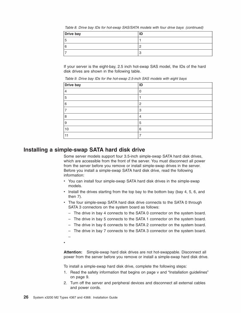
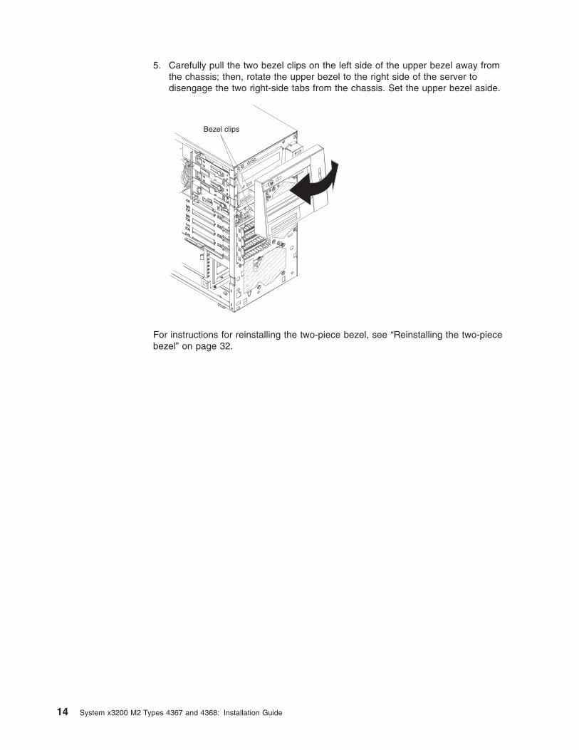
Table 8. Drive bay IDs for hot-swap SAS/SATA models with four drive bays (continued)
Drive bay ID
5 1
6 2
7 3
If your server is the eight-bay, 2.5 inch hot-swap SAS model, the IDs of the harddisk drives are shown in the following table.
Table 9. Drive bay IDs for the hot-swap 2.5-inch SAS models with eight bays
Drive bay ID
4 0
5 1
6 2
7 3
8 4
9 5
10 6
11 7
Installing a simple-swap SATA hard disk driveSome server models support four 3.5-inch simple-swap SATA hard disk drives,which are accessible from the front of the server. You must disconnect all powerfrom the server before you remove or install simple-swap drives in the server.Before you install a simple-swap SATA hard disk drive, read the followinginformation:
v You can install four simple-swap SATA hard disk drives in the simple-swapmodels.
v Install the drives starting from the top bay to the bottom bay (bay 4, 5, 6, andthen 7).
v The four simple-swap SATA hard disk drive connects to the SATA 0 throughSATA 3 connectors on the system board as follows:
– The drive in bay 4 connects to the SATA 0 connector on the system board.
– The drive in bay 5 connects to the SATA 1 connector on the system board.
– The drive in bay 6 connects to the SATA 2 connector on the system board.
– The drive in bay 7 connects to the SATA 3 connector on the system board.
–
v
Attention: Simple-swap hard disk drives are not hot-swappable. Disconnect allpower from the server before you remove or install a simple-swap hard disk drive.
To install a simple-swap hard disk drive, complete the following steps:
1. Read the safety information that begins on page v and “Installation guidelines”on page 9.
2. Turn off the server and peripheral devices and disconnect all external cablesand power cords.
26 System x3200 M2 Types 4367 and 4368: Installation Guide

3. Unlock the side cover (the bezel will not disengage from the server if the coveris locked).
4. Remove the lower bezel (see “Removing the two-piece bezel” on page 13).
5. Touch the static-protective package that contains the drive to any unpaintedmetal surface on the server; then, remove the drive from the package and placeit on a static-protective surface.
6. Align the drive assembly with the guide rails in the bay (the connector end ofthe drive goes in first).
7. Pull the loops of the drive assembly toward each other; then, carefully slide thedrive assembly into the drive bay until it stops, and release the loops.
Note: Do not release the loops on the drive assembly until it is completelyseated.
If you have other devices to install or remove, do so now; otherwise, go to“Completing the installation” on page 32.
The simple-swap-drive backplate controls the IDs of the internal simple-swap drivebays. The following table lists the IDs of the hard disk drives and backplate insimple-swap models. This table applies only to server models that support four harddisk drives.
Table 10. Drive bay IDs for simple-swap models
Drive bay ID
4 0
5 1
6 2
7 3
Chapter 2. Installing optional devices 27

Power and signal cables for internal drivesThe server uses cables to connect SATA-attached, simple-swap SATA, hot-swapSAS, and hot-swap SATA devices to the power supply and to the system board.(For the locations of the system-board connectors, see the User’s Guide on the IBMSystem x Documentation CD.) Review the following information before you connectpower and signal cables to internal drives:
v The drives that are preinstalled in the server come with power and signal cablesattached. If you replace any drives, remember which cable is attached to whichdrive.
v When you install a drive, make sure that one of the signal cable connectors isconnected to the drive and that the connector at the other end of the signal cableis connected to the system board.
The following cables are provided:
v Power cables: Four-wire power cables connect the drives to the power supply.At the ends of these cables are plastic connectors that can be attached todifferent drives; these connectors vary in size. Use either a four-wire power cableor SATA power cable with SATA drives, but do not use both at the same time(use one or the other).
v Signal cables: Signal cables are typically flat cables, also called ribbon cables,that connect SATA attached, SATA, SAS, and diskette drives to the systemboard. Two or three types of signal cables come with the server:
– SATA attached (for optical drives): The flat SATA-attached signal cable hastwo connectors. One of these connectors is attached to the optical drive, andone is attached to one of the connectors on the system board.
– (Optional) USB diskette drive: The narrower signal cable has twoconnectors. One is attached to the diskette drive, and the other is connectedto the floppy drive connector (J11) on the system board.
– Simple-swap SATA: Simple-swap SATA models come with four SATA cablesthat are already connected to the system board and the backplate at the rearof the simple-swap drive cage.
– Hot-swap SAS/SATA: Hot-swap SAS/SATA models come with a single datacable that connects the SAS/SATA controller to the hot-swap backplane. Thiscable provides inherent connectivity for the four SAS or SATA drives that theserver supports. Therefore, additional cabling is not required for these drives.
For more information about the requirements for SAS/SATA cable andconnecting SAS/SATA devices, see the documentation that comes with thesedevices.
For a list of supported optional devices for the server, seehttp://www.ibm.com/servers/eserver/serverproven/compat/us/.
Installing an adapterThe following notes describe the types of adapters that the server supports andother information that you must consider when you install an adapter.
v Locate the documentation that comes with the adapter and follow thoseinstructions in addition to the instructions in this section. If you have to changethe switch setting or jumper settings on the adapter, follow the instructions thatcome with the adapter.
v Read the documentation that comes with your operating system.
v The server comes with the following adapter connectors or slots:
– Slot 1, PCI Express x8
28 System x3200 M2 Types 4367 and 4368: Installation Guide

– Slot 2, PCI Express x4 (x1)
Important: The x4 designation in parentheses for slot 2 identifies an x4 slotthat is designed to support x4 and x1 adapters that can downshift to operateat the x1 bandwidth. For example, if you install an x4 adapter in slot 2 thatcan downshift to x1 bandwidth, it will run at the x1 bandwidth. The x4connector (slot 2) can be used for x1 and x4 adapters. Check the informationthat comes with your adapter for compatibility information.
– Slot 3, PCI-X 64-bit/133 MHz
Note: PCI-X slot 3 is enabled when the optional mini-PCI-X enablement cardis installed in the mini-PCI slot on the system board. When nomini-PCI-X enablement card is installed, PCI-X slot 3 has no function.
– Slot 4, PCI 32-bit/33 MHz
– Slot 5, PCI 32-bit/33 MHz
v Some server models come with a mini-SAS/SATA RAID controller installed. TheSAS/SATA RAID controller enables integrated RAID level-0 and level-1. Somemodels also come with a ServeRAID-MR10i SAS/SATA controller that enablesintegrated RAID level-5 capability.
v The ServeRAID-MR10i SAS/SATA controller must be installed in slot 1, PCIExpress x8.
v You can install the mini-PCI-X enablement card or the mini-SAS/SATA RAIDcontroller in the mini-PCI slot on the system board.
v When the optional mini-PCI-X enablement card is installed in the mini-PCI slot, itpasses PCI-X signals from the mini-PCI-X Enablement Card to PCI-X slot 3.
v When the optional mini-PCI-X enablement card is installed in the server, theserver cannot support RAID level-0 and level-1.
v You can install full-length adapters that are included in the ServerProven list inslots 1 through 5 (depending on your model).
v The 64-bit slot 3 supports 3.3 V PCI-X adapters.
v The 32-bit slots 4 and 5 support 5.0 V keyed PCI adapters; they do not support3.3 V keyed adapters. Universal adapters are supported in slots 4 and 5 if theyare universally keyed.
v An optional IBM Remote Supervisor Adapter II SlimLine can be installed only inthe dedicated connector on the system board. For additional information, see thedocumentation that comes with this adapter.
v When you start the server for the first time after you install a Remote SupervisorAdapter II SlimLine, the startup process will take several minutes longer than atypical startup.
v The server scans PCI Express x8 slot 1, PCI Express x4 slot 2, PCI-X slot 3, andPCI slots 4 and 5 to assign system resources. Then, the server starts the PCIdevices in the following order, if you have not changed the default startupsequence: PCI Express x8 slot 1, PCI Express x4 slot 2, PCI-X slot 3, PCI slot 4,and PCI slot 5.
v For a list of supported optional devices for the server, see http://www.ibm.com/servers/eserver/serverproven/compat/us/.
For the locations of the expansion slots on the system board, see the User’s Guideon the IBM System x Documentation CD.
Chapter 2. Installing optional devices 29

Attention: Static electricity that is released to internal server components whenthe server is powered-on might cause the server to stop, which might result in theloss of data. To avoid this potential problem, always use an electrostatic-dischargewrist strap or other grounding system when you work inside the server with thepower on.
To install an adapter, complete the following steps:
1. Read the safety information that begins on page v and “Installation guidelines”on page 9.
2. Turn off the server and peripheral devices and disconnect all external cablesand power cords; then, remove the side cover. See “Removing the side cover”on page 12.
3. Follow the cabling instructions, if any, that come with the adapter. Route theadapter cables before you install the adapter.
4. Follow the instructions that come with the adapter to set jumpers or switches, ifany.
5. Rotate the rear adapter-retention bracket to the open (unlocked) position andremove it from the server.
6. Remove the screw that secures the expansion-slot cover to the chassis. Storethe expansion-slot cover and screw in a safe place for future use.
Note: Expansion-slot covers must be installed on all vacant slots. Thismaintains the electronic emissions standards of the server and ensuresproper ventilation of server components.
7. Touch the static-protective package that contains the adapter to any unpaintedmetal surface on the server. Then, remove the adapter from thestatic-protective package. Avoid touching the components and gold-edgeconnectors on the adapter.
8. If you are installing a full-length adapter, remove the blue adapter guide (if any)from the end of the adapter.
Adapter guide
9. Carefully grasp the adapter by the top edge or upper corners, and align it withthe expansion-slot guides; then, press the adapter firmly into the expansionslot. Move the adapter directly from the static-protective package to theexpansion slot.
Attention: Make sure that the adapter is correctly seated in the expansionslot before you turn on the server. Incomplete installation of an adapter mightdamage the system board or the adapter.
30 System x3200 M2 Types 4367 and 4368: Installation Guide
Left sideRight side
Front adapterretention bracket
Adapter
Expansion-slotscrew
Rear adapterretentionbracket
10. Install an expansion-slot screw at the rear of the adapter.
11. If you are installing a full-length adapter, press on the release lever on the rightside of the front adapter-retention bracket to release the retaining tab on theleft side of the bracket.
12. Connect required cables to the adapter. Route cables so that they do not blockthe flow of air from the fans.
13. Reinstall the rear adapter-retention bracket; then, rotate the bracket to theclosed position.
Note: If any adapters in the server are large or have heavy cables attached tothem, you can remove the rear adapter-retention bracket and secure allof the adapters with expansion-slot screws.
If you have other devices to install or remove, do so now; otherwise, go to“Completing the installation” on page 32.
Chapter 2. Installing optional devices 31

Completing the installationTo complete the installation, you must reinstall the two-piece bezel, reinstall the sidecover, connect all the cables and, for some devices, run the Configuration/SetupUtility program. Follow the instructions in this section.
Reinstalling the two-piece bezelTo reinstall the two-piece bezel, complete the following steps:
1. Install the upper bezel:
a. Insert the two right-side tabs on the upper bezel into the matching holes onthe right side of the chassis.
b. Rotate the upper bezel to the left side of the chassis and press the bezelclips into the matching indentations on the left side of the chassis until thebezel clips snap into place.
32 System x3200 M2 Types 4367 and 4368: Installation Guide

2. Install the lower bezel:
a. Insert the two bottom tabs on the lower bezel into the matching holes in thefront of the chassis.
b. Rotate the top of the lower bezel up to the chassis; then, press the bluerelease tab on the right side of the lower bezel and completely close thelower bezel until it locks securely into place.
Chapter 2. Installing optional devices 33

Reinstalling the side coverIf you removed the bezel, reinstall it before you reinstall the side cover. See“Reinstalling the two-piece bezel” on page 32.
Note: The rear adapter-retention bracket rests against the server side cover. Youmight find it easier to lay the server on its side to reinstall the side cover.
To reinstall the side cover, complete the following steps:
1. Before you install the side cover, make sure that all cables, adapters, and othercomponents are installed and seated correctly and that you have not left loosetools or parts inside the server. Also, make sure that all internal cables arecorrectly routed.
Note: The cover-release latch must be in the unlocked (opened) position beforeyou install the side cover.
2. Position the lip on the bottom edge of the side cover on the ledge on the bottomof the chassis; then, rotate the cover up to the chassis, and then press down onthe cover release latch and push the cover completely closed until it latchessecurely into place.
Cover-releaselatch
Key lock
3. Close the cover-release latch to secure the side cover in place.
4. Lock the side cover.
34 System x3200 M2 Types 4367 and 4368: Installation Guide

Connecting the cablesAttention: To prevent damage to equipment, connect the power cords last.
If the server cables and connector panel have color-coded connectors, match thecolor of each cable end with the color of the connector. For example, match a bluecable end to a blue connector on the panel, a red cable end with a red connector,and so on.
The following illustration shows the input/output (I/O) connectors on the rear of theserver.
Table 11. Connectors on the rear of the server
Serial 2 (Com2)
Serial 1 (Com1)
Video
USB 3 and 4
USB 1 and 2
RemoteSupervisorAdapter IISlimLine(Ethernet)
Ethernetconnector
Parallel
Power cordAC power LEDDC power LED
Ethernet transmit/receive activity LED(amber)
Ethernet linkstatus LED(green)
AC power LEDDC power LED
Chapter 2. Installing optional devices 35

Updating the server configurationWhen you start the server for the first time after you add or remove an internal orexternal device, you might receive a message that the configuration has changed.The Configuration/Setup Utility program starts automatically so that you can savethe new configuration settings. For more information, see the section aboutconfiguring the server in the User's Guide on the IBM System x Documentation CD.
Some optional devices have device drivers that you must install. For informationabout installing device drivers, see the documentation that comes with each device.
If the server has a ServeRAID adapter and you have installed or removed a harddisk drive, see the ServeRAID documentation that comes with the server forinformation about reconfiguring the disk arrays.
If you have installed a Remote Supervisor Adapter II SlimLine to manage the serverremotely, see the Remote Supervisor Adapter II documentation for informationabout setting up, configuring, and using the adapter.
36 System x3200 M2 Types 4367 and 4368: Installation Guide

Chapter 3. Server controls, LEDs, and power
This section describes the controls and light-emitting diodes (LEDs) and how to turnthe server on and off.
Front viewThe following illustration shows the controls, LEDs, and connectors on the front ofthe server.
CD-eject orDVD-eject button
CD or DVD driveactivity LED
Hard disk driveactivity LED
Power-onLEDPower-controlbutton
System-errorLED
USB connectors
Optionaldiskette-ejectbuttonOptionaldiskette driveactivity LED
Power-on LEDWhen this LED is lit and not flashing, it indicates that the server is turnedon. When this LED is flashing, it indicates that the server is turned off andstill connected to an ac power source. When this LED is off, it indicates thatac power is not present, or the power supply or the LED itself has failed. Apower LED is also on the rear of the server.
Note: If this LED is off, it does not mean that there is no electrical power inthe server. The LED might be burned out. To remove all electricalpower from the server, you must disconnect the power cords fromthe electrical outlets.
Power-control buttonPress this button to turn the server on and off manually.
Hard disk drive activity LEDWhen this LED is flashing, it indicates that the associated hard disk drive isin use.
System-error LEDWhen this amber LED is lit, it indicates that a system error has occurred.An LED on the system board might also be lit to help isolate the error. SeeChapter 5, “Solving problems,” on page 47 for additional information.
© Copyright IBM Corp. 2009 37
Detailed troubleshooting information is in the Problem Determination andService Guide on the IBM System x Documentation CD.
Note: When a PCI Express error LED and the system-error LED is lit, itindicates that a PCI Express error has occurred. The system-errorLED will turn off when you reboot the server. When a DIMM errorLED and the system-error LED is lit, it indicates that a DIMM errorhas occurred. After you correct the DIMM error, the DIMM error LEDand the system-error LED will turn off.
USB connectorsConnect USB devices to these connectors.
CD-eject or DVD-eject buttonPress this button to release a CD from the CD drive or a DVD from theDVD drive.
CD or DVD drive activity LEDWhen this LED is lit, it indicates that the CD drive or DVD drive is in use.
(Optional) diskette-eject buttonPress this button to release a diskette from the diskette drive.
(Optional) diskette drive activity LEDWhen this LED is lit, it indicates that the diskette drive is in use.
Hot-swap hard disk drive activity LED (some models)On some server models, each hot-swap drive has a hard disk drive activityLED. When this green LED is flashing, it indicates that the associated harddisk drive is in use.
When the drive is removed, this LED also is visible on the hard disk drivebackplane, next to the drive connector. The backplane is the printed circuitboard behind drive bays 4 through 7 (or bays 4 through 11 on some2.5-inch hard disk drive SAS models).
Hot-swap hard disk drive status LED (some models)On some server models, each hot-swap hard disk drive has an amberstatus LED. If this amber status LED for a drive is lit, it indicates that theassociated hard disk drive has failed.
If an optional IBM ServeRAID controller is installed in the server and theLED flashes slowly (one flash per second), it indicates that the drive isbeing rebuilt. When the LED is flashing rapidly (three flashes per second), itindicates that the controller is identifying the drive.
When the drive is removed, this LED also is visible on the hard disk drivebackplane, below the hot-swap hard disk drive activity LED.
38 System x3200 M2 Types 4367 and 4368: Installation Guide

Rear viewThe following illustration shows the connectors and LEDs on the rear of the server.
Serial 2 (Com2)
Serial 1 (Com1)
Video
USB 3 and 4
USB 1 and 2
RemoteSupervisorAdapter IISlimLine(Ethernet)
Ethernetconnector
Parallel
Power cordAC power LEDDC power LED
Ethernet transmit/receive activity LED(amber)
Ethernet linkstatus LED(green)
Power-cord connectorConnect the power cord to this connector.
AC power LEDOn some server models, each hot-swap power supply has an ac powerLED and a dc power LED. During typical operation, both the ac and dcpower LEDs are lit.
DC power LEDOn some server models, each hot-swap power supply has a dc power LEDand an ac power LED. During typical operation, both the ac and dc powerLEDs are lit.
Serial 2 connectorConnect a 9-pin serial device to this connector.
Parallel connectorConnect a parallel device to this connector.
Serial 1 connectorConnect a 9-pin serial device to this connector.
Video connectorConnect a monitor to this connector.
USB connectorsConnect USB devices to these connectors.
Ethernet connectorUse this connector to connect the server to a network.
Chapter 3. Server controls, LEDs, and power 39
Ethernet transmit/receive activity LEDThis LED is on the Ethernet connector on the rear of the server. When thisLED is lit, it indicates that there is activity between the server and thenetwork.
Ethernet link status LEDThis LED is on the Ethernet connector on the rear of the server. When thisLED is lit, it indicates that there is an active connection on the Ethernetport.
Remote Supervisor Adapter II SlimLine/Ethernet connectorUse this connector to connect the Remote Supervisor Adapter II SlimLine toa network.
Server power featuresWhen the server is connected to an ac power source but is not turned on, theoperating system does not run, and all core logic except the service processor isshut down; however, the server can respond to requests from the service processor,such as a remote request to turn on the server. The power-on LED flashes toindicate that the server is connected to ac power but not turned on.
Turning on the serverApproximately 20 seconds after the server is connected to ac power, thepower-control button becomes active, and one or more fans might start running toprovide cooling while the server is connected to power. You can turn on the serverand start the operating system by pressing the power-control button.
The server can also be turned on in any of the following ways:
v If a power failure occurs while the server is turned on, the server will restartautomatically when power is restored.
v If your operating system supports the systems-management software for anoptional Remote Supervisor Adapter II SlimLine, the systems-managementsoftware can turn on the server.
v If your operating system supports the Wake on LAN feature, the Wake on LANfeature can turn on the server.
v If an optional Remote Supervisor Adapter II SlimLine is installed in the server, theserver can be turned on from the Remote Supervisor Adapter II SlimLine userinterface.
Note: When 4 GB or more of memory (physical or logical) is installed, somememory is reserved for various system resources and is unavailable to theoperating system. The amount of memory that is reserved for systemresources depends on the operating system, the configuration of the server,and the configured PCI optional devices.
Turning off the serverWhen you turn off the server and leave it connected to ac power, the server canrespond to requests from the service processor, such as a remote request to turnon the server. While the server remains connected to ac power, one or more fansmight continue to run. To remove all power from the server, you must disconnect itfrom the power source.
40 System x3200 M2 Types 4367 and 4368: Installation Guide

Some operating systems require an orderly shutdown before you turn off the server.See your operating-system documentation for information about shutting down theoperating system.
Statement 5:
CAUTION:The power control button on the device and the power switch on the powersupply do not turn off the electrical current supplied to the device. The devicealso might have more than one power cord. To remove all electrical currentfrom the device, ensure that all power cords are disconnected from the powersource.
1
2
The server can be turned off in any of the following ways:
v You can turn off the server from the operating system, if your operating systemsupports this feature. After an orderly shutdown of the operating system, theserver will be turned off automatically.
v You can press the power-control button to start an orderly shutdown of theoperating system and turn off the server, if your operating system supports thisfeature.
v If the operating system stops functioning, you can press and hold thepower-control button for more than 4 seconds to turn off the server.
v If an optional Remote Supervisor Adapter II SlimLine is installed in the server, theserver can be turned off from the Remote Supervisor Adapter II SlimLine userinterface.
v If the Wake on LAN feature turned on the server, the Wake on LAN feature canturn off the server.
v The server can turn itself off as an automatic response to a critical systemfailure.
Chapter 3. Server controls, LEDs, and power 41

42 System x3200 M2 Types 4367 and 4368: Installation Guide

Chapter 4. Configuring the server
The ServerGuide Setup and Installation CD provides software setup tools andinstallation tools that are specifically designed for your IBM server. Use this CDduring the initial installation of the server to configure basic hardware features andto simplify the operating-system installation.
In addition to the ServerGuide Setup and Installation CD, you can use the followingconfiguration programs to customize the server hardware:
v Configuration/Setup Utility program
v Mini-baseboard management controller utility programs
v Boot Menu program
v Broadcom NetXtreme Gigabit Ethernet Boot Agent
v Broadcom NetXtreme Gigabit Ethernet controller configuration
v LSI Logic Configuration Utility program
For more information about these programs, see “Configuring the server” in theUser's Guide on the IBM System x Documentation CD.
Using the ServerGuide Setup and Installation CDThe ServerGuide Setup and Installation CD provides programs to detect the servermodel and installed optional hardware devices, configure the server hardware,provide device drivers, and help you install the operating system. For informationabout the supported operating-system versions, see the label on the CD. If theServerGuide Setup and Installation CD did not come with the server, to downloadthe latest version, go to http://www.ibm.com/systems/management/serverguide/sub.html and click IBM Service and Support Site.
Note: Changes are made periodically to the IBM Web site. The actual proceduremight vary slightly from what is described in this document.
To start the ServerGuide Setup and Installation CD, complete the following steps:
1. Insert the CD, and restart the server. If the CD does not start, see “ServerGuideproblems” on page 69.
2. Follow the instructions on the screen to:
a. Select your language.
b. Select your keyboard layout and country.
c. View the overview to learn about ServerGuide features.
d. View the readme file to review installation tips about your operating systemand adapter.
e. Start the setup and hardware configuration programs.
f. Start the operating-system installation. You will need your operating-systemCD.
© Copyright IBM Corp. 2009 43

Using the Configuration/Setup Utility programConfiguration/Setup is a menu-driven utility that is part of the BIOS. You can use itto perform the following tasks:
v Change interrupt request (IRQ) settings
v Change the startup sequence
v Configure serial port assignments
v Resolve configuration conflicts
v Set the date and time
v Set passwords and security settings
To start the Configuration/Setup Utility program, complete the following steps:
1. Turn on the server. If the server is already on when you start this procedure,you must shut down the operating system, turn off the server, wait a fewseconds until all in-use LEDs are turned off, and restart the server.
2. When the message Press F1 for Configuration/Setup, Press F12 for BootMenu is displayed, press F1. (This prompt is displayed on the screen for only afew seconds. You must press F1 quickly.) If you have set both a power-onpassword and an administrator password, you must type the administratorpassword to access the full Configuration/Setup Utility menu.
3. Follow the instructions on the screen.
Using the Boot Menu programThe Boot Menu program is a built in, menu-driven configuration program that youcan use to temporarily redefine the first startup device without changing settings inthe Configuration/Setup Utility program.
To use the Boot Menu program, complete the following steps:
1. Restart the server.
2. Press F12.
3. Select the startup device.
The next time the server is started, it returns to the startup sequence that is set inthe Configuration/Setup Utility program.
Enabling the Broadcom NetXtreme Gigabit Ethernet Boot AgentThe Broadcom NetXtreme Gigabit Ethernet Boot Agent is part of the BIOS. You canuse it to configure the network as a startable device, and you can customize wherethe network Startup optional devices occurs in the startup sequence. Enable anddisable the Broadcom NetXtreme Gigabit Ethernet Boot Agent from theConfiguration/Setup Utility program.
To enable the Broadcom NetXtreme Gigabit Ethernet boot agent, complete thefollowing steps:
1. From the Configuration/Setup Utility main menu, select Devices and I/O Portsand press Enter. Select Planar Ethernet and set it to Enabled, if it is notalready enabled. Press Esc to exit.
2.
44 System x3200 M2 Types 4367 and 4368: Installation Guide

3. From the Start Options menu choice, press Enter and make sure that PlanarEthernet PXE/DHCP is set to Enabled. Select Startup Sequence Options andpress Enter; then, set the network-planar device as the first startup device.
4. Press Esc twice to exit.
5. Select Save Settings in the Configuration/Setup Utility main menu and pressEnter to save your changes.
Configuring the Broadcom NetXtreme Gigabit Ethernet controllerThe Ethernet controller is integrated on the system board. It provides an interfacefor connecting to a 10 Mbps, 100 Mbps, or 1 Gbps network and provides full duplex(FDX) capability, which enables simultaneous transmission and reception of data onthe network. If the Ethernet port in the server supports auto-negotiation, thecontroller detects the data-transfer rate (10BASE-T, 100BASE-TX, or 1000BASE-T)and duplex mode (full-duplex or half-duplex) of the network and automaticallyoperates at that rate and mode.
You do not have to set any jumpers or configure the controller. However, you mustinstall a device driver to enable the operating system to address the controller. Fordevice drivers and information about configuring the Ethernet controller, see theBroadcom NetXtreme Gigabit Ethernet Software CD that comes with the server. Tofind updated information about configuring the controller, complete the followingsteps.
Note: Changes are made periodically to the IBM Web site. The actual proceduremight vary slightly from what is described in this document.
1. Go to http://www.ibm.com/systems/support/
2. Under Product support , click System x.
3. Under Popular links, click Publications lookup.
4. From the Product family menu, select System x3200 M2 and click Continue.
LSI Configuration Utility programUse the LSI Configuration Utility program to configure and manage redundant arrayof independent disks (RAID) arrays. Be sure to use these programs as described inthis document.
v Use the LSI Configuration Utility program to:
– Perform a low-level format on a SAS hard disk drive
– Create an array of SAS hard disk drives with or without a hot-spare drive
– Set SAS protocol parameters on SAS hard disk drives
The integrated SAS/SATA controller with RAID capabilities supports RAID arrays.You can use the LSI Configuration Utility program to configure RAID 1 (IM), RAID1E (IME), and RAID 0 (IS) for a single pair of attached devices. If you install adifferent type of RAID adapter, follow the instructions in the documentation thatcomes with the adapter to view or change SAS settings for attached devices.
In addition, you can download an LSI command-line configuration program fromhttp://www.ibm.com/systems/support/.
Consider the following information when you are using the LSI Configuration Utilityprogram to configure and manage arrays:
Chapter 4. Configuring the server 45

v The integrated SAS/SATA controller with RAID capabilities supports the followingfeatures:
– Integrated Mirroring (IM) with hot-spare support (also known as RAID 1)
Use this option to create an integrated array of two disks plus up to twooptional hot spare. All data on the primary disk can be migrated.
– Integrated Mirroring Enhanced (IME) with hot-spare support (also known asRAID 1E)
Use this option to create an integrated mirror enhanced array of three to eightdisks, including up to two optional hot spare. All data on the array disks will bedeleted.
– Integrated Striping (IS) (also known as RAID 0)
Use this option to create an integrated striping array of two to eight disks. Alldata on the array disk will be deleted.
v Hard disk drive capacities affect how you create arrays. The drives in an arraycan have different capacities, but the RAID controller treats them as if they allhave the capacity of the smallest hard disk drive.
v If you use an integrated SAS/SATA controller with RAID capabilities to configurea RAID 1 (mirrored) array after you have installed the operating system, you willlose access to any data or applications that were previously stored on thesecondary drive of the mirrored pair.
v If you install a different type of RAID controller, see the documentation thatcomes with the controller for information about viewing and changing SASsettings for attached devices.
To start the LSI Configuration Utility program, complete the following steps:
1. Turn on the server.
2. When the message <<< Press <CTRL-C> to start LSI Configuration Utility>>> is displayed, press Ctrl-C. If an administrator password has been set, youare prompted to type the password.
3. Use the arrow keys to select a controller (channel) from the list of adapters;then, press Enter.
4. To change the settings of the selected items, follow the instructions on thescreen. If you select Raid Properties, SAS Topology, or Advanced AdapterProperties, additional screens are displayed.
When you have finished changing settings, press Esc to exit from the program;select Save to save the settings that you have changed.
See the User’s Guide on the IBM System x Documentation CD for more informationabout the LSI Configuration Utility program.
46 System x3200 M2 Types 4367 and 4368: Installation Guide

Chapter 5. Solving problems
This chapter provides basic troubleshooting information to help you solve somecommon problems that might occur while you are setting up the server.
If you cannot locate and correct a problem by using the information in this chapter,see Appendix A, “Getting help and technical assistance,” on page 73, the ProblemDetermination and Service Guide on the IBM System x Documentation CD, and the“Server Support” flowchart in the front of this document.
Diagnostic tools overviewThe following tools are available to help you diagnose and solve hardware-relatedproblems:
v POST beep codes
The power-on self-test beep codes indicate the detection of a problem.
– One beep indicates successful completion of POST, with no errors.
– More than one beep indicates that POST detected a problem. Error messagesare displayed also if POST detects a hardware-configuration problem.
See “POST beep codes” and the Problem Determination and Service Guideon the IBM System x Documentation CD for more information.
v Troubleshooting tables
These tables list problem symptoms and actions to correct the problems. See“Troubleshooting tables” on page 58 for more information.
v Diagnostic programs and error messages
The Dynamic System Analysis (DSA) Preboot diagnostic programs are theprimary method of testing the major components of the server. These programsare on the IBM Dynamic System Analysis Preboot Diagnostic CD. If this CD didnot come with the server, complete the following steps to download it.
Note: Changes are made periodically to the IBM Web site. The actual proceduremight vary slightly from what is described in this document.
1. Go to http://www.ibm.com/systems/support/.
2. Under Product support, click System x.
3. Under Popular links, click Software and device drivers.
4. Click Dynamic System Analysis (DSA).
For additional information about the DSA diagnostic programs, see the ProblemDetermination and Service Guide on the IBM System x Documentation CD.
v System-board error LEDs
An LED on the system board might be lit to help isolate an error that is indicatedby the system-error LED on the front of the server. See “System-board LEDs” onpage 71 for more information.
POST beep codesPOST emits one beep to signal successful completed. If POST detects a problemduring startup, other beep codes might occur. Use the following beep codedescriptions to help diagnose and solve problems that are detected during startup.
© Copyright IBM Corp. 2009 47

Note: See the Problem Determination and Service Guide on the IBM System xDocumentation CD for more information about the POST beep codes.
One beepPOST was completed successfully without detecting any errors.
Repeating long beepsA memory error has occurred. Make sure that all DIMMs are correctlyinstalled.
Other beep codesSee the Problem Determination and Service Guide on the IBM System xDocumentation CD for information about other beep codes.
POST error codesThe following table provides an abbreviated list of the error codes that might appearduring POST. See the Problem Determination and Service Guide on the IBMSystem x Documentation CD for more information about the POST error codes. Tocheck for updated technical information, complete the following steps.
Note: Changes are made periodically to the IBM Web site. The actual proceduremight vary slightly from what is described in this document.
1. Go to http://www.ibm.com/systems/support/.
2. Under Product support, click System x.
3. Under Popular links, click Publications lookup.
4. From the Product family menu, select System x3200 M2 and click Continue.
Table 12. Abbreviated list of POST error codes
v Follow the suggested actions in the order in which they are listed in the Action column until the problemis solved.
v See the parts listing in the Problem Determination and Service Guide to determine which components arecustomer replaceable units (CRU) and which components are field replaceable units (FRU).
v If an action step is preceded by “(Trained service technician only),” that step must be performed only by atrained service technician.
Error code Description Action
062 Three consecutive boot failures using thedefault configuration.
1. Update the system firmware to the latestlevel (see the Problem Determinationand Service Guide on the IBM System xDocumentation CD).
2. (Trained service technician only) Replacethe system board.
101 Tick timer internal interrupt failure. (Trained service technician only) Replace thesystem board.
102 Internal timer channel 2 test failure. (Trained service technician only) Replace thesystem board.
48 System x3200 M2 Types 4367 and 4368: Installation Guide

Table 12. Abbreviated list of POST error codes (continued)
v Follow the suggested actions in the order in which they are listed in the Action column until the problemis solved.
v See the parts listing in the Problem Determination and Service Guide to determine which components arecustomer replaceable units (CRU) and which components are field replaceable units (FRU).
v If an action step is preceded by “(Trained service technician only),” that step must be performed only by atrained service technician.
Error code Description Action
106 Diskette controller error. 1. Make sure that the Configuration/SetupUtility program correctly reflects thediskette drive information.
2. Reseat the diskette drive cable.
3. Reseat the diskette drive.
4. Replace the following components one ata time, in the order shown, restarting theserver each time:
a. Diskette drive cable
b. Diskette drive
c. (Trained service technician only)System board
151 Real-time clock error. 1. Reseat the battery.
2. Replace the following components one ata time, in the order shown, restarting theserver each time:
a. Battery
b. (Trained service technician only)System board
162 Invalid configuration information or CMOSrandom-access memory (RAM) checksumfailure.
1. Run the Configuration/Setup Utilityprogram, select Load Default Settings,and save the settings.
2. Reseat the following components:
a. Battery
b. Failing device (if the device is a FRU,the device must be reseated by atrained service technician only)
3. Replace the following components one ata time, in the order shown, restarting theserver each time:
a. Battery
b. Failing device (if the device is a FRU,the device must be replaced by atrained service technician only)
c. (Trained service technician only)System board
Chapter 5. Solving problems 49

Table 12. Abbreviated list of POST error codes (continued)
v Follow the suggested actions in the order in which they are listed in the Action column until the problemis solved.
v See the parts listing in the Problem Determination and Service Guide to determine which components arecustomer replaceable units (CRU) and which components are field replaceable units (FRU).
v If an action step is preceded by “(Trained service technician only),” that step must be performed only by atrained service technician.
Error code Description Action
163 Time of day not set. 1. Run the Configuration/Setup Utilityprogram, select Load Default Settings,make sure that the date and time arecorrect, and save the settings.
2. Reseat the battery.
3. Clear CMOS. See the ProblemDetermination and Service Guide forinformation about how to clear CMOS.
4. Replace the following components one ata time, in the order shown, restarting theserver each time:
a. Battery
b. (Trained service technician only)System board
164 Memory size has changed. 1. Run the Configuration/Setup Utilityprogram, select Load Default Settings.
2. Reseat the DIMM.
3. Replace the following components one ata time, in the order shown, restarting theserver each time:
a. DIMM
b. (Trained service technician only)System board
175 Service processor flash code damaged ornot loaded.Note: In this case, the service processor isthe optional Remote Supervisor Adapter IISlimLine.
1. Update the Remote Supervisor Adapter IISlimLine firmware (see the ProblemDetermination and Service Guide on theIBM System x Documentation CD).
2. Replace the Remote Supervisor AdapterII SlimLine.
178 Security hardware error. 1. Run the Configuration/Setup Utilityprogram, select Load Default Settings,and save the settings.
2. (Trained service technician only) Replacethe system board.
50 System x3200 M2 Types 4367 and 4368: Installation Guide
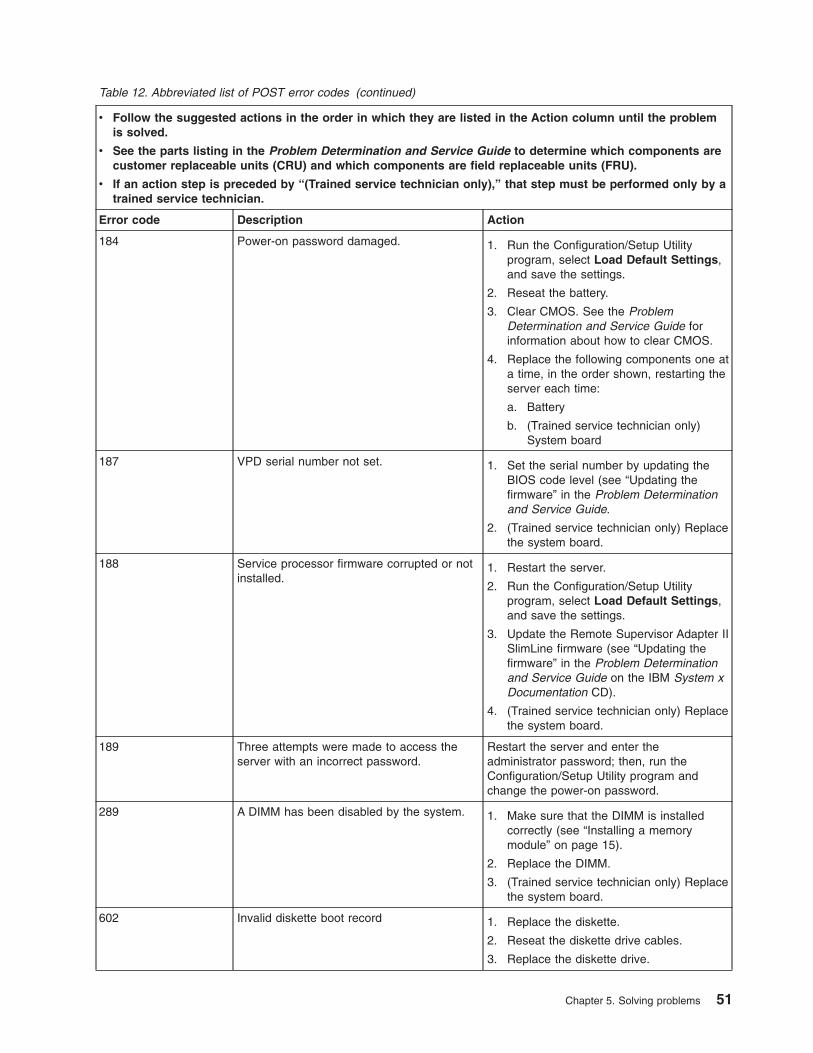
Table 12. Abbreviated list of POST error codes (continued)
v Follow the suggested actions in the order in which they are listed in the Action column until the problemis solved.
v See the parts listing in the Problem Determination and Service Guide to determine which components arecustomer replaceable units (CRU) and which components are field replaceable units (FRU).
v If an action step is preceded by “(Trained service technician only),” that step must be performed only by atrained service technician.
Error code Description Action
184 Power-on password damaged. 1. Run the Configuration/Setup Utilityprogram, select Load Default Settings,and save the settings.
2. Reseat the battery.
3. Clear CMOS. See the ProblemDetermination and Service Guide forinformation about how to clear CMOS.
4. Replace the following components one ata time, in the order shown, restarting theserver each time:
a. Battery
b. (Trained service technician only)System board
187 VPD serial number not set. 1. Set the serial number by updating theBIOS code level (see “Updating thefirmware” in the Problem Determinationand Service Guide.
2. (Trained service technician only) Replacethe system board.
188 Service processor firmware corrupted or notinstalled.
1. Restart the server.
2. Run the Configuration/Setup Utilityprogram, select Load Default Settings,and save the settings.
3. Update the Remote Supervisor Adapter IISlimLine firmware (see “Updating thefirmware” in the Problem Determinationand Service Guide on the IBM System xDocumentation CD).
4. (Trained service technician only) Replacethe system board.
189 Three attempts were made to access theserver with an incorrect password.
Restart the server and enter theadministrator password; then, run theConfiguration/Setup Utility program andchange the power-on password.
289 A DIMM has been disabled by the system. 1. Make sure that the DIMM is installedcorrectly (see “Installing a memorymodule” on page 15).
2. Replace the DIMM.
3. (Trained service technician only) Replacethe system board.
602 Invalid diskette boot record 1. Replace the diskette.
2. Reseat the diskette drive cables.
3. Replace the diskette drive.
Chapter 5. Solving problems 51

Table 12. Abbreviated list of POST error codes (continued)
v Follow the suggested actions in the order in which they are listed in the Action column until the problemis solved.
v See the parts listing in the Problem Determination and Service Guide to determine which components arecustomer replaceable units (CRU) and which components are field replaceable units (FRU).
v If an action step is preceded by “(Trained service technician only),” that step must be performed only by atrained service technician.
Error code Description Action
604 Internal diskette drive error 1. Run the Configuration/Setup Utilityprogram, select Load Default Settings,and save the settings.
2. Reseat the diskette drive signal cables.
3. Replace the diskette drive.
962 Parallel port configuration error 1. Run the Configuration/Setup Utilityprogram and make sure that the parallelport setting is correct.
2. (Trained service technician only) Replacethe system board.
1162 Serial port error 1. Run the Configuration/Setup Utilityprogram and make sure that the serialport settings are correct.
2. (Trained service technician only) Replacethe system board.
1600 The service processor is not functioning. (Trained service technician only) Replace thesystem board.
1601 System-management adaptercommunication error.
1. Update the BMC firmware (see“Updating the Firmware” in the ProblemDetermination and Service Guide on theIBM System x Documentation CD).
2. (Trained service technician only) Replacethe system board.
1603 System-management adaptercommunication error.
1. Make sure that the Remote SupervisorAdapter II SlimLine is installed correctly.
2. Update the Remote Supervisor Adapter IISlimLine firmware (see “Updating thefirmware” in the Problem Determinationand Service Guide on the IBM System xDocumentation CD).
3. Reseat the following components:
a. Adapter
b. (Trained service technician only)System board
4. Replace the following components one ata time, in the order shown, restarting theserver each time:
a. Remote Supervisor Adapter IISlimLine
b. (Trained service technician only)Replace the system board.
52 System x3200 M2 Types 4367 and 4368: Installation Guide

Table 12. Abbreviated list of POST error codes (continued)
v Follow the suggested actions in the order in which they are listed in the Action column until the problemis solved.
v See the parts listing in the Problem Determination and Service Guide to determine which components arecustomer replaceable units (CRU) and which components are field replaceable units (FRU).
v If an action step is preceded by “(Trained service technician only),” that step must be performed only by atrained service technician.
Error code Description Action
1762 Hard disk drive configuration error. 1. Run the Configuration/Setup Utilityprogram and load the default settings.
2. Reseat the following components:
a. Hard disk drive cables
b. Hard disk drive
c. (Trained service technician only)System board
3. Replace the following components one ata time, in the order shown, restarting theserver each time.
a. Hard disk drive cables
b. Hard disk drive
c. (Trained service technician only)System board
178x Fixed disk error.Note: x is the drive that has the error.
1. Run the hard disk drive diagnostic testson drive x (see “Running the diagnosticprograms” in the Problem Determinationand Service Guide on the IBM System xDocumentation CD).
2. Reseat the following components,depending on the server model:
v Hot-swap models: Hard disk drive
v Simple-swap models:
a. Hard disk drive x
b. Hard disk drive x cable
3. Replace the following components one ata time, depending on the server model,in the order shown, restarting the servereach time:
v Hot-swap models:
a. Hard disk drive x
b. Hard disk drive backplane
v Simple-swap models:
a. Hard disk drive x
b. Hard disk drive x cable
4. (Trained service technician only) Replacethe system board.
1800 Unavailable PCI hardware interrupt. 1. Run the Configuration/Setup Utilityprogram and adjust the adapter settings.
2. Remove each adapter one at a time,restarting the server each time, until thefailing adapter is isolated.
Chapter 5. Solving problems 53

Table 12. Abbreviated list of POST error codes (continued)
v Follow the suggested actions in the order in which they are listed in the Action column until the problemis solved.
v See the parts listing in the Problem Determination and Service Guide to determine which components arecustomer replaceable units (CRU) and which components are field replaceable units (FRU).
v If an action step is preceded by “(Trained service technician only),” that step must be performed only by atrained service technician.
Error code Description Action
1801 A PCI or PCI Express adapter has requestedmemory resources that are not available.
1. Make sure that no devices have beendisabled in the Configuration/Setup Utilityprogram.
2. Change the order of the adapters in thePCI and PCI Express slots. Make surethat the startup (boot) device ispositioned early in the scanning order.(For information about the scanningorder, see the User’s Guide on the IBMSystem x Documentation CD).
3. Make sure that the settings for theadapter and all other adapters in theConfiguration/Setup Utility program arecorrect. If the memory resource settingsare not correct, change them.
4. If all memory resources are being used,remove an adapter to make memoryavailable to the adapter. Disabling theBIOS on the adapter should correct theerror. See the documentation that comeswith the adapter.
1802 No more I/O space is available for a PCI orPCI Express adapter.
1. If the error code indicates a particularPCI or PCI Express slot or device,remove that device.
2. Reseat each adapter.
3. Replace the following components one ata time, in the order shown, restarting theserver each time:
a. Failing PCI or PCI Express adapter
b. (Trained service technician only)System board
1803 No more memory (above 1 MB for a PCI orPCI Express adapter).
1. If the error code indicates a particularPCI or PCI Express slot or device,remove that device.
2. Reseat each adapter.
3. Replace the following components one ata time, in the order shown, restarting theserver each time:
a. Failing PCI or PCI Express adapter
b. (Trained service technician only)System board
54 System x3200 M2 Types 4367 and 4368: Installation Guide

Table 12. Abbreviated list of POST error codes (continued)
v Follow the suggested actions in the order in which they are listed in the Action column until the problemis solved.
v See the parts listing in the Problem Determination and Service Guide to determine which components arecustomer replaceable units (CRU) and which components are field replaceable units (FRU).
v If an action step is preceded by “(Trained service technician only),” that step must be performed only by atrained service technician.
Error code Description Action
1804 No more memory (below 1 MB for a PCI orPCI Express adapter).
1. Remove the failing adapter.
2. Reseat each adapter.
3. Replace the following components one ata time, in the order shown, restarting theserver each time:
a. Failing PCI or PCI Express adapter
b. (Trained service technician only)System board
1805 PCI option ROM checksum error. 1. Remove the failing adapter.
2. Reseat each adapter.
3. Replace the following components one ata time, in the order shown, restarting theserver each time:
a. Failing PCI or PCI Express adapter
b. (Trained service technician only)System board
1806 PCI or PCI Express built in self-test failure. 1. If the error code indicates a particularPCI or PCI Express slot or device,remove that device.
2. Reseat the following components:
a. Each adapter
b. (Trained service technician only, ifthe specified board is a FRU) Theboard that is indicated in the errorcode
3. Replace the components listed in step 2one at a time, in the order shown,restarting the server each time.
1807 General PCI error. 1. Make sure that no devices have beendisabled in the Configuration/Setup Utilityprogram.
2. Replace each adapter one at a time,restarting the server each time.
Chapter 5. Solving problems 55

Table 12. Abbreviated list of POST error codes (continued)
v Follow the suggested actions in the order in which they are listed in the Action column until the problemis solved.
v See the parts listing in the Problem Determination and Service Guide to determine which components arecustomer replaceable units (CRU) and which components are field replaceable units (FRU).
v If an action step is preceded by “(Trained service technician only),” that step must be performed only by atrained service technician.
Error code Description Action
1962 A drive does not contain a valid boot sector. 1. Make sure that a bootable operatingsystem is installed.
2. Run the hard disk drive diagnostic tests(see “Running the diagnostic programs”in the Problem Determination andService Guide on the IBM System xDocumentation CD).
3. Reseat the following components,depending on the server model:
v Hot-swap models:
a. Hard disk drive
b. SAS/SATA controller
v Simple-swap models:
a. Hard disk drive
b. Hard disk drive cable
4. Replace the following components one ata time, depending on the server model,in the order shown, restarting the servereach time:
v Hot-swap models:
a. Hard disk drive
b. Hard disk drive backplane
c. SAS/SATA controller
v Simple-swap models:
a. Hard disk drive
b. Hard disk drive cable
5. (Trained service technician only) Replacethe system board.
2462 Video memory configuration error. 1. Reseat the following components:
a. Video adapter (if one is installed)
b. (Trained service technician only)System board
2. Replace the following components one ata time, in the order shown, restarting theserver each time:
a. Video adapter (if one is installed)
b. (Trained service technician only)System board
3001 SMART monitoring failure predicted on harddisk drive
Replace the hard disk drive.
3003 SMART command execution failure on harddisk drive
Replace the hard disk drive.
56 System x3200 M2 Types 4367 and 4368: Installation Guide

Table 12. Abbreviated list of POST error codes (continued)
v Follow the suggested actions in the order in which they are listed in the Action column until the problemis solved.
v See the parts listing in the Problem Determination and Service Guide to determine which components arecustomer replaceable units (CRU) and which components are field replaceable units (FRU).
v If an action step is preceded by “(Trained service technician only),” that step must be performed only by atrained service technician.
Error code Description Action
3005 Current hard disk drive configuration do notsupport SMART function
Replace the hard disk drive.
5962 DVD drive configuration error. 1. Run the Configuration/Setup Utilityprogram and load the default settings(see “Using the Configuration/SetupUtility program” on page 44).
2. Reseat the following components:
a. DVD drive cable
b. DVD drive
c. System board
3. Replace the components listed in step 2one at a time, in the order shown,restarting the server each time.
00012000 Processor machine check error. 1. (Trained service technician only) Reseatthe microprocessor.
2. Replace the following components one ata time, in the order shown, restarting theserver each time:
a. (Trained service technician only)Microprocessor
b. (Trained service technician only)System board
00019701 Microprocessor failed the built in self-test(BIST).
1. (Trained service technician only) Reseatthe microprocessor.
2. Replace the following components one ata time, in the order shown, restarting theserver each time:
a. (Trained service technician only)Microprocessor
b. (Trained service technician only)System board
01298001 No update data for microprocessor. 1. Update the BIOS code again (see theProblem Determination and ServiceGuide on the IBM System xDocumentation CD).
2. (Trained service technician only) Reseatthe microprocessor.
3. (Trained service technician only) Replacethe microprocessor.
Chapter 5. Solving problems 57
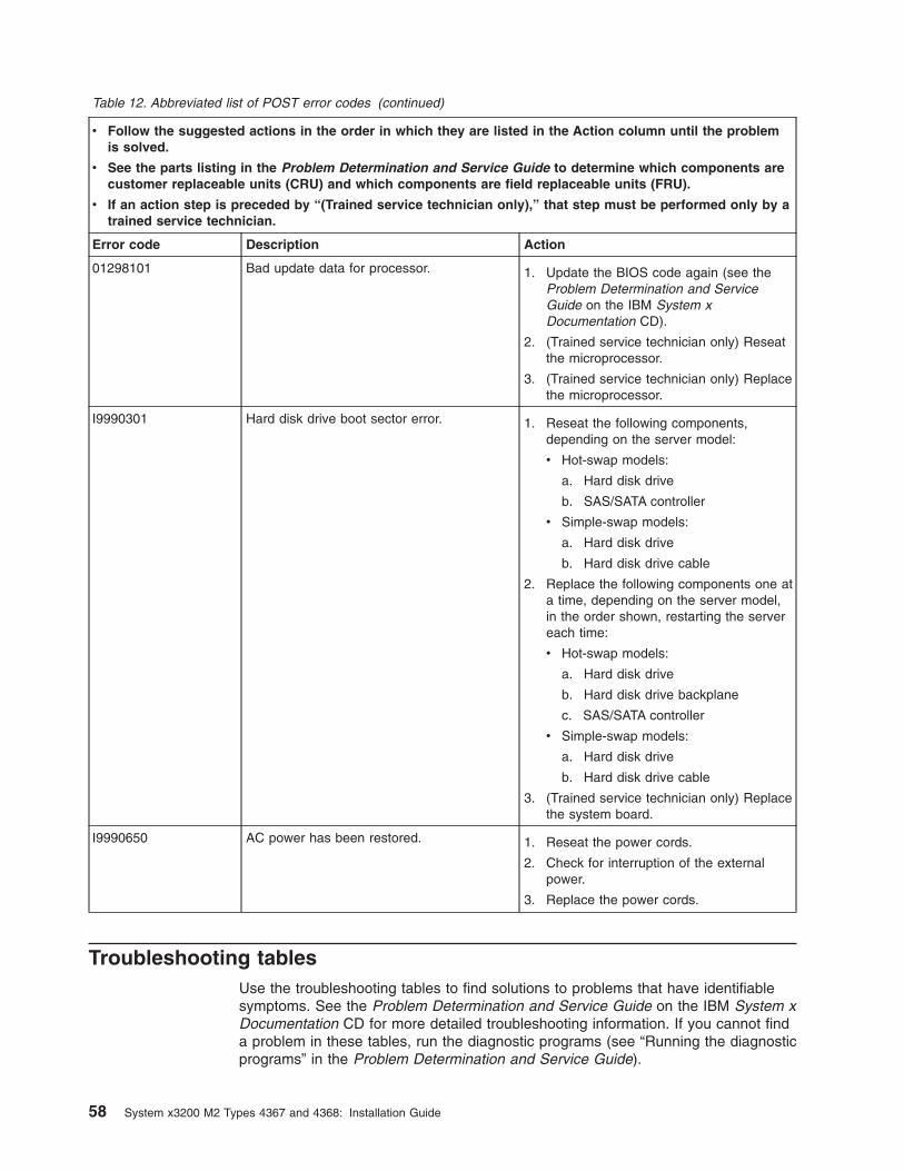
Table 12. Abbreviated list of POST error codes (continued)
v Follow the suggested actions in the order in which they are listed in the Action column until the problemis solved.
v See the parts listing in the Problem Determination and Service Guide to determine which components arecustomer replaceable units (CRU) and which components are field replaceable units (FRU).
v If an action step is preceded by “(Trained service technician only),” that step must be performed only by atrained service technician.
Error code Description Action
01298101 Bad update data for processor. 1. Update the BIOS code again (see theProblem Determination and ServiceGuide on the IBM System xDocumentation CD).
2. (Trained service technician only) Reseatthe microprocessor.
3. (Trained service technician only) Replacethe microprocessor.
I9990301 Hard disk drive boot sector error. 1. Reseat the following components,depending on the server model:
v Hot-swap models:
a. Hard disk drive
b. SAS/SATA controller
v Simple-swap models:
a. Hard disk drive
b. Hard disk drive cable
2. Replace the following components one ata time, depending on the server model,in the order shown, restarting the servereach time:
v Hot-swap models:
a. Hard disk drive
b. Hard disk drive backplane
c. SAS/SATA controller
v Simple-swap models:
a. Hard disk drive
b. Hard disk drive cable
3. (Trained service technician only) Replacethe system board.
I9990650 AC power has been restored. 1. Reseat the power cords.
2. Check for interruption of the externalpower.
3. Replace the power cords.
Troubleshooting tablesUse the troubleshooting tables to find solutions to problems that have identifiablesymptoms. See the Problem Determination and Service Guide on the IBM System xDocumentation CD for more detailed troubleshooting information. If you cannot finda problem in these tables, run the diagnostic programs (see “Running the diagnosticprograms” in the Problem Determination and Service Guide).
58 System x3200 M2 Types 4367 and 4368: Installation Guide

If you have just added new software or a new optional device and the server is notworking, complete the following steps before you use the troubleshooting tables:
1. Check the system-board LEDs or the LEDs on the front panel (see“System-board LEDs” on page 71).
2. Remove the software or device that you just added.
3. Run the diagnostic tests to determine whether the server is running correctly.
4. Reinstall the new software or new device.
CD or DVD drive problems
v Follow the suggested actions in the order in which they are listed in the Action column until the problemis solved.
v See the parts listing in the Problem Determination and Service Guide to determine which components arecustomer replaceable units (CRU) and which components are field replaceable units (FRU).
v If an action step is preceded by “(Trained service technician only),” that step must be performed only by atrained service technician.
Symptom Action
The CD or DVD drive is notrecognized.
1. Make sure that:
v The SATA channel to which the CD or DVD drive is attached (primary orsecondary) is enabled in the Configuration/Setup Utility program.
v All cables and jumpers are installed correctly.
v The correct device driver is installed for the CD or DVD drive.
2. Run the CD or DVD drive diagnostic programs.
3. Reseat the CD or DVD drive cable.
4. Replace the following components one at a time, in the order shown, restartingthe server each time:
a. CD or DVD drive cable
b. CD or DVD drive
c. (Trained service technician only) System board
5. Replace the components listed in step 4 one at a time, in the order shown,restarting the server each time.
A CD or DVD is not workingcorrectly.
1. Clean the CD or DVD.
2. Run the CD or DVD drive diagnostic programs.
3. Reseat the CD or DVD drive cable.
4. Replace the following components one at a time, in the order shown, restartingthe server each time:
a. CD or DVD drive cable
b. CD or DVD drive
The CD or DVD drive tray is notworking.
1. Make sure that the server is turned on.
2. Insert the end of a straightened paper clip into the manual tray-releaseopening.
3. Reseat the CD or DVD drive cable.
4. Replace the following components one at a time, in the order shown, restartingthe server each time:
a. CD or DVD drive cable
b. CD or DVD drive
Chapter 5. Solving problems 59
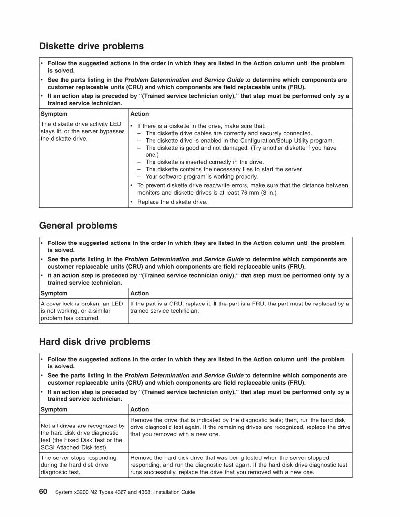
Diskette drive problems
v Follow the suggested actions in the order in which they are listed in the Action column until the problemis solved.
v See the parts listing in the Problem Determination and Service Guide to determine which components arecustomer replaceable units (CRU) and which components are field replaceable units (FRU).
v If an action step is preceded by “(Trained service technician only),” that step must be performed only by atrained service technician.
Symptom Action
The diskette drive activity LEDstays lit, or the server bypassesthe diskette drive.
v If there is a diskette in the drive, make sure that:– The diskette drive cables are correctly and securely connected.– The diskette drive is enabled in the Configuration/Setup Utility program.– The diskette is good and not damaged. (Try another diskette if you have
one.)– The diskette is inserted correctly in the drive.– The diskette contains the necessary files to start the server.– Your software program is working properly.
v To prevent diskette drive read/write errors, make sure that the distance betweenmonitors and diskette drives is at least 76 mm (3 in.).
v Replace the diskette drive.
General problems
v Follow the suggested actions in the order in which they are listed in the Action column until the problemis solved.
v See the parts listing in the Problem Determination and Service Guide to determine which components arecustomer replaceable units (CRU) and which components are field replaceable units (FRU).
v If an action step is preceded by “(Trained service technician only),” that step must be performed only by atrained service technician.
Symptom Action
A cover lock is broken, an LEDis not working, or a similarproblem has occurred.
If the part is a CRU, replace it. If the part is a FRU, the part must be replaced by atrained service technician.
Hard disk drive problems
v Follow the suggested actions in the order in which they are listed in the Action column until the problemis solved.
v See the parts listing in the Problem Determination and Service Guide to determine which components arecustomer replaceable units (CRU) and which components are field replaceable units (FRU).
v If an action step is preceded by “(Trained service technician only),” that step must be performed only by atrained service technician.
Symptom Action
Not all drives are recognized bythe hard disk drive diagnostictest (the Fixed Disk Test or theSCSI Attached Disk test).
Remove the drive that is indicated by the diagnostic tests; then, run the hard diskdrive diagnostic test again. If the remaining drives are recognized, replace the drivethat you removed with a new one.
The server stops respondingduring the hard disk drivediagnostic test.
Remove the hard disk drive that was being tested when the server stoppedresponding, and run the diagnostic test again. If the hard disk drive diagnostic testruns successfully, replace the drive that you removed with a new one.
60 System x3200 M2 Types 4367 and 4368: Installation Guide

v Follow the suggested actions in the order in which they are listed in the Action column until the problemis solved.
v See the parts listing in the Problem Determination and Service Guide to determine which components arecustomer replaceable units (CRU) and which components are field replaceable units (FRU).
v If an action step is preceded by “(Trained service technician only),” that step must be performed only by atrained service technician.
Symptom Action
A hard disk drive was notdetected while the operatingsystem was being started.
Reseat all hard disk drives and cables; then, run the hard disk drive diagnostictests again.
A hard disk drive passes thediagnosticDiskDriveDiagnosticTest but theproblem remains.
Run the diagnostic DiskDriveDiagnosticTest (see “Running the diagnosticprograms” in the Problem Determination and Service Guide on the IBM System xDocumentation CD).
Intermittent problems
v Follow the suggested actions in the order in which they are listed in the Action column until the problemis solved.
v See the parts listing in the Problem Determination and Service Guide to determine which components arecustomer replaceable units (CRU) and which components are field replaceable units (FRU).
v If an action step is preceded by “(Trained service technician only),” that step must be performed only by atrained service technician.
Symptom Action
A problem occurs onlyoccasionally and is difficult todiagnose.
1. Make sure that:v All cables and cords are connected securely to the rear of the server and
attached devices.v When the server is turned on, air is flowing from the fan grille. If there is no
airflow, the fan is not working. This can cause the server to overheat andshut down.
2. Check the system event/error log (see “Error logs” in the ProblemDetermination and Service Guide on the IBM System x Documentation CD).
Chapter 5. Solving problems 61

Keyboard, mouse, or pointing-device problems
v Follow the suggested actions in the order in which they are listed in the Action column until the problemis solved.
v See the parts listing in the Problem Determination and Service Guide to determine which components arecustomer replaceable units (CRU) and which components are field replaceable units (FRU).
v If an action step is preceded by “(Trained service technician only),” that step must be performed only by atrained service technician.
Symptom Action
All or some keys on thekeyboard do not work.
1. Make sure that:
v The keyboard is compatible with the server. See http://www.ibm.com/servers/eserver/serverproven/compat/us/.
v The keyboard cable is securely connected.
v The server and the monitor are turned on.
2. If you are using a USB keyboard, run the Configuration/Setup Utility programand enable keyboardless operation to prevent a POST error message frombeing displayed during startup.
3. If you are using a USB keyboard and it is connected to a USB hub, disconnectthe USB keyboard from the hub and connect it directly to the server.
4. Replace the following components one at a time, in the order shown, restartingthe server each time:
a. Keyboard
b. (Trained service technician only) System board
The mouse or pointing devicedoes not work.
1. Make sure that:
v The mouse is compatible with the server. See http://www.ibm.com/servers/eserver/serverproven/compat/us/.
v The mouse or pointing-device cable is securely connected to the server.
v The mouse or pointing-device drivers are installed correctly.
v The server and the monitor are turned on.
v The mouse option is enabled in the Configuration/Setup Utility program.
2. If you are using a USB mouse or pointing device and it is connected to a USBhub, disconnect the mouse or pointing device from the hub and connect itdirectly to the server.
3. Replace the following components one at a time, in the order shown, restartingthe server each time:
a. Mouse or pointing device
b. (Trained service technician only) System board
62 System x3200 M2 Types 4367 and 4368: Installation Guide

Memory problems
v Follow the suggested actions in the order in which they are listed in the Action column until the problemis solved.
v See the parts listing in the Problem Determination and Service Guide to determine which components arecustomer replaceable units (CRU) and which components are field replaceable units (FRU).
v If an action step is preceded by “(Trained service technician only),” that step must be performed only by atrained service technician.
Symptom Action
The amount of system memorythat is displayed is less than theamount of installed physicalmemory.
1. Make sure that:
v No error LEDs are lit on the front-panel assembly or on the system board.
v The memory modules are seated correctly.
v You have installed the correct type of memory.
v If you changed the memory, you updated the memory configuration in theConfiguration/Setup Utility program.
v All DIMMs are enabled. The server might have automatically disabled aDIMM when it detected a problem.
v If a DIMM was disabled by a system-management interrupt (SMI), replacethe DIMM.
2. Check the POST error log for error message 289. If POST error message 289is in the error log, perform the actions listed in the POST error codes table (see“POST error codes” on page 48). Otherwise, continue to step 3.
3. Run memory diagnostics (see “Running the diagnostic programs” in theProblem Determination and Service Guide on the IBM System x DocumentationCD).
4. Make sure that there is no memory mismatch when the server is over theminimum memory configuration (one 512 MB DIMM) and that you haveinstalled the correct number of DIMMs (see the User’s Guide on the IBMSystem x Documentation CD for information about the supported DIMMconfigurations).
5. Reseat the DIMMs.
6. Replace the following components one at a time, in the order shown, restartingthe server each time:
a. DIMMs
b. (Trained service technician only) System board
Chapter 5. Solving problems 63

Microprocessor problems
v Follow the suggested actions in the order in which they are listed in the Action column until the problemis solved.
v See the parts listing in the Problem Determination and Service Guide to determine which components arecustomer replaceable units (CRU) and which components are field replaceable units (FRU).
v If an action step is preceded by “(Trained service technician only),” that step must be performed only by atrained service technician.
Symptom Action
The server emits a continuousbeep during POST, indicatingthat the startup (boot)microprocessor is not workingcorrectly.
1. Make sure that the microprocessor is supported on this server.
2. (Trained service technician only) Make sure that the microprocessor is seatedcorrectly.
3. Replace the following components one at a time, in the order shown, restartingthe server each time:
a. (Trained service technician only) Microprocessor
b. (Trained service technician only) System board
Monitor problemsSome IBM monitors have their own self-tests. If you suspect a problem with yourmonitor, see the information that comes with the monitor for instructions for testingand adjusting the monitor.
v Follow the suggested actions in the order in which they are listed in the Action column until the problemis solved.
v See the parts listing in the Problem Determination and Service Guide to determine which components arecustomer replaceable units (CRU) and which components are field replaceable units (FRU).
v If an action step is preceded by “(Trained service technician only),” that step must be performed only by atrained service technician.
Symptom Action
Testing the monitor 1. Make sure that the monitor cables are firmly connected.
2. Try using a different monitor on the server, or try using the monitor that is beingtested on a different server.
3. Run the diagnostic programs. If the monitor passes the diagnostic programs,the problem might be a video device driver.
4. Reseat the Remote Supervisor Adapter II SlimLine (if one is installed).
5. Replace the Remote Supervisor Adapter II SlimLine (if one is installed).
6. (Trained service technician only) Replace the system board.
64 System x3200 M2 Types 4367 and 4368: Installation Guide

v Follow the suggested actions in the order in which they are listed in the Action column until the problemis solved.
v See the parts listing in the Problem Determination and Service Guide to determine which components arecustomer replaceable units (CRU) and which components are field replaceable units (FRU).
v If an action step is preceded by “(Trained service technician only),” that step must be performed only by atrained service technician.
Symptom Action
The screen is blank. 1. Make sure that:v The server is turned on. If there is no power to the server, see “Power
problems” on page 68.v The monitor cables are connected correctly.v The monitor is turned on and the brightness and contrast controls are
adjusted correctly.v A single beep sounds when the server is turned on, indicating the successful
completion of POST..
2. Make sure that the correct server is controlling the monitor, if applicable.
3. Make sure that damaged BIOS code is not affecting the video; see “Recoveringfrom a BIOS update failure” in the Problem Determination and Service Guideon the IBM System x Documentation CD.
4. See “Solving undetermined problems” in the Problem Determination andService Guide.
The monitor works when youturn on the server, but thescreen goes blank when youstart some applicationprograms.
1. Make sure that:
v The application program is not setting a display mode that is higher than thecapability of the monitor.
v You installed the necessary device drivers for the application.
2. Run video diagnostics (see “Running the diagnostic programs” in the ProblemDetermination and Service Guide on the IBM System x Documentation CD).
v If the server passes the video diagnostics, the video is good; see “Solvingundetermined problems” in the Problem Determination and Service Guide.
v (Trained service technician only) If the server fails the video diagnostics,replace the system board.
Chapter 5. Solving problems 65

v Follow the suggested actions in the order in which they are listed in the Action column until the problemis solved.
v See the parts listing in the Problem Determination and Service Guide to determine which components arecustomer replaceable units (CRU) and which components are field replaceable units (FRU).
v If an action step is preceded by “(Trained service technician only),” that step must be performed only by atrained service technician.
Symptom Action
The monitor has screen jitter, orthe screen image is wavy,unreadable, rolling, or distorted.
1. If the monitor self-tests show that the monitor is working correctly, consider thelocation of the monitor. Magnetic fields around other devices (such astransformers, appliances, fluorescent lights, and other monitors) can causescreen jitter or wavy, unreadable, rolling, or distorted screen images. If thishappens, turn off the monitor.
Attention: Moving a color monitor while it is turned on might cause screendiscoloration.
Move the device and the monitor at least 305 mm (12 in.) apart, and turn onthe monitor.
Notes:
a. To prevent diskette drive read/write errors, make sure that the distancebetween the monitor and any external diskette drive is at least 76 mm (3in.).
b. Non-IBM monitor cables might cause unpredictable problems.
2. Reseat the monitor cable.
3. Reseat the Remote Supervisor Adapter II SlimLine
4. Replace the following components one at a time, in the order shown, restartingthe server each time:
a. Monitor
b. Remote Supervisor Adapter II SlimLine
c. (Trained service technician only) System board
Wrong characters appear on thescreen.
1. If the wrong language is displayed, update the BIOS code with the correctlanguage (see “Updating the firmware” in the Problem Determination andService Guide on the IBM System x Documentationd CD).
2. Reseat the monitor cable.
3. Replace the following components one at a time, in the order shown, restartingthe server each time:
a. Monitor
b. (Trained service technician only) System board
66 System x3200 M2 Types 4367 and 4368: Installation Guide

Optional-device problems
v Follow the suggested actions in the order in which they are listed in the Action column until the problemis solved.
v See the parts listing in the Problem Determination and Service Guide to determine which components arecustomer replaceable units (CRU) and which components are field replaceable units (FRU).
v If an action step is preceded by “(Trained service technician only),” that step must be performed only by atrained service technician.
Symptom Action
An IBM optional device that wasjust installed does not work.
1. Make sure that:v The device is designed for the server (see http://www.ibm.com/servers/
eserver/serverproven/compat/us/).v You followed the installation instructions that came with the device and the
device is installed correctly.v You have not loosened any other installed devices or cables.v You updated the configuration information in the Configuration/Setup Utility
program. Whenever memory or any other device is changed, you mustupdate the configuration.
2. Reseat the device that you just installed.
3. Replace the device that you just installed.
An IBM optional device thatused to work does not worknow.
1. Make sure that all of the cable connections for the device are secure.
2. If the device comes with test instructions, use those instructions to test thedevice.
3. Reseat the failing device.
4. Replace the failing device.
Chapter 5. Solving problems 67

Power problems
v Follow the suggested actions in the order in which they are listed in the Action column until the problemis solved.
v See the parts listing in the Problem Determination and Service Guide to determine which components arecustomer replaceable units (CRU) and which components are field replaceable units (FRU).
v If an action step is preceded by “(Trained service technician only),” that step must be performed only by atrained service technician.
Symptom Action
The power-control button doesnot work (the server does notstart).Note: The power-control buttonwill not function until 20seconds after the server hasbeen connected to ac power.
1. Make sure that the front-panel assembly power-control button is workingcorrectly:
a. Disconnect the server power cords.
b. Reconnect the power cords.
c. Press the power-control button.
2. Make sure that:v The power cords are correctly connected to the server and to a working
electrical outlet.v The server contains the correct type of DIMMs.v The DIMMs are correctly seated.v The LEDs on the power supply do not indicate a problem.v The microprocessor is correctly installed.
3. Reseat the following components:
a. DIMMs
b. Power supply cables to all internal components
c. Power supplies (hot-swap models)
4. Replace the following components one at a time, in the order shown, restartingthe server each time:
a. DIMMs
b. Power supplies (hot-swap models)
c. (Trained service technician only) Power supply (non-hot swap models)
5. If you just installed an optional device, remove it, and restart the server. If theserver now starts, you might have installed more devices than the power supplysupports.
6. See “Power-supply LEDs” and “Solving undetermined problems” in the ProblemDetermination and Service Guide on the IBM System x Documentation CD.
The server does not turn off. 1. Determine whether you are using an Advanced Configuration and PowerManagement (ACPI) or a non-ACPI operating system. If you are using anon-ACPI operating system, complete the following steps:
a. Press Ctrl+Alt+Delete.
b. Turn off the server by holding the power-control button for 5 seconds.
c. Restart the server.
d. If the server fails POST and the power-control button does not work,disconnect the ac power cord for 20 seconds; then, reconnect the ac powercord and restart the server.
2. (Trained service technician only) If the problem remains or if you are using anACPI-aware operating system, suspect the system board.
The server unexpectedly shutsdown, and the LEDs on thefront-panel assembly are not lit.
See “Solving undetermined problems” in the Problem Determination and ServiceGuide on the IBM System x Documentation CD.
68 System x3200 M2 Types 4367 and 4368: Installation Guide
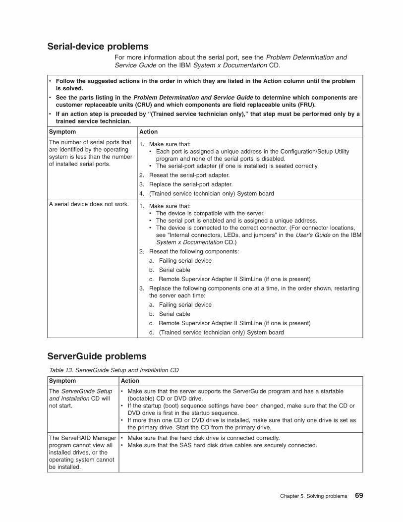
Serial-device problemsFor more information about the serial port, see the Problem Determination andService Guide on the IBM System x Documentation CD.
v Follow the suggested actions in the order in which they are listed in the Action column until the problemis solved.
v See the parts listing in the Problem Determination and Service Guide to determine which components arecustomer replaceable units (CRU) and which components are field replaceable units (FRU).
v If an action step is preceded by “(Trained service technician only),” that step must be performed only by atrained service technician.
Symptom Action
The number of serial ports thatare identified by the operatingsystem is less than the numberof installed serial ports.
1. Make sure that:v Each port is assigned a unique address in the Configuration/Setup Utility
program and none of the serial ports is disabled.v The serial-port adapter (if one is installed) is seated correctly.
2. Reseat the serial-port adapter.
3. Replace the serial-port adapter.
4. (Trained service technician only) System board
A serial device does not work. 1. Make sure that:v The device is compatible with the server.v The serial port is enabled and is assigned a unique address.v The device is connected to the correct connector. (For connector locations,
see “Internal connectors, LEDs, and jumpers” in the User’s Guide on the IBMSystem x Documentation CD.)
2. Reseat the following components:
a. Failing serial device
b. Serial cable
c. Remote Supervisor Adapter II SlimLine (if one is present)
3. Replace the following components one at a time, in the order shown, restartingthe server each time:
a. Failing serial device
b. Serial cable
c. Remote Supervisor Adapter II SlimLine (if one is present)
d. (Trained service technician only) System board
ServerGuide problemsTable 13. ServerGuide Setup and Installation CD
Symptom Action
The ServerGuide Setupand Installation CD willnot start.
v Make sure that the server supports the ServerGuide program and has a startable(bootable) CD or DVD drive.
v If the startup (boot) sequence settings have been changed, make sure that the CD orDVD drive is first in the startup sequence.
v If more than one CD or DVD drive is installed, make sure that only one drive is set asthe primary drive. Start the CD from the primary drive.
The ServeRAID Managerprogram cannot view allinstalled drives, or theoperating system cannotbe installed.
v Make sure that the hard disk drive is connected correctly.v Make sure that the SAS hard disk drive cables are securely connected.
Chapter 5. Solving problems 69

Table 13. ServerGuide Setup and Installation CD (continued)
Symptom Action
The operating-systeminstallation programcontinuously loops.
Make more space available on the hard disk.
The ServerGuideprogram will not start theoperating-system CD.
Make sure that the operating-system CD is supported by the ServerGuide program. Seethe ServerGuide Setup and Installation CD label for a list of supported operating-systemversions.
The operating systemcannot be installed; theoption is not available.
Make sure that the server supports the operating-system. If it does, either no logical driveis defined (RAID servers), or the ServerGuide System Partition is not present. Run theServerGuide program and make sure that setup is complete.
Software problems
v Follow the suggested actions in the order in which they are listed in the Action column until the problemis solved.
v See the parts listing in the Problem Determination and Service Guide to determine which components arecustomer replaceable units (CRU) and which components are field replaceable units (FRU).
v If an action step is preceded by “(Trained service technician only),” that step must be performed only by atrained service technician.
Symptom Action
You suspect a softwareproblem.
1. To determine whether the problem is caused by the software, make sure that:v The server has the minimum memory that is needed to use the software. For
memory requirements, see the information that comes with the software. Ifyou have just installed an adapter or memory, the server might have amemory-address conflict.
v The software is designed to operate on the server.v Other software works on the server.v The software works on another server.
2. If you receive any error messages while you use the software, see theinformation that comes with the software for a description of the messages andsuggested solutions to the problem.
3. Contact your place of purchase of the software.
70 System x3200 M2 Types 4367 and 4368: Installation Guide

Universal Serial Bus (USB) device problems
v Follow the suggested actions in the order in which they are listed in the Action column until the problemis solved.
v See the parts listing in the Problem Determination and Service Guide to determine which components arecustomer replaceable units (CRU) and which components are field replaceable units (FRU).
v If an action step is preceded by “(Trained service technician only),” that step must be performed only by atrained service technician.
Symptom Action
A USB device does not work. 1. Run USB diagnostics (see “Running the diagnostic programs” in the ProblemDetermination and Service Guide on the IBM System x Documentation CD).
2. Make sure that:v The correct USB device driver is installed.v The operating system supports USB devices.
3. Make sure that the USB configuration options are set correctly in theConfiguration/Setup Utility program. (For more information, see the User’sGuide on the IBM System x Documentation CD.)
4. If you are using a USB hub, disconnect the USB device from the hub andconnect it directly to the server.
System-board LEDsThe following illustration shows the LEDs on the system board. You might have torefer to this illustration when you are solving problems with the server.
Slot 5, PCI 32-bit 33 MHz LED
Slot 4, PCI 32-bit 33 MHz LED
Slot 3, PCI-X 64-bit 133 MHz LED
Slot 2, PCI Express x4 LED
Slot 1, PCI Express x8 LED
Standby power LED
Microprocessorfan LED
DIMM 1LED
DIMM 2LED
DIMM 3LED
DIMM 4LED
System fan LED
Hard drivefan LED
Mini-PCI slotLED
Microprocessor LED
Board VRD fault LED
Mini-BMCheartbeat LED
Chapter 5. Solving problems 71
Use the system-board LEDs to diagnose system errors. An error LED is lit toindicate a problem with a specific component. After a problem is corrected, its LEDwill not be lit the next time that the server is restarted; if the problem remains, theLED will be lit again. For additional information, see the Problem Determination andService Guide on the IBM System x Documentation CD.
72 System x3200 M2 Types 4367 and 4368: Installation Guide

Appendix A. Getting help and technical assistance
If you need help, service, or technical assistance or just want more informationabout IBM® products, you will find a wide variety of sources available from IBM toassist you. This section contains information about where to go for additionalinformation about IBM and IBM products, what to do if you experience a problemwith your system, and whom to call for service, if it is necessary.
Before you callBefore you call, make sure that you have taken these steps to try to solve theproblem yourself:
v Check all cables to make sure that they are connected.
v Check the power switches to make sure that the system and any optionaldevices are turned on.
v Use the troubleshooting information in your system documentation, and use thediagnostic tools that come with your system. Information about diagnostic tools isin the Problem Determination and Service Guide on the IBM Documentation CDthat comes with your system.
v Go to the IBM support Web site at http://www.ibm.com/systems/support/ to checkfor technical information, hints, tips, and new device drivers or to submit arequest for information.
You can solve many problems without outside assistance by following thetroubleshooting procedures that IBM provides in the online help or in thedocumentation that is provided with your IBM product. The documentation thatcomes with IBM systems also describes the diagnostic tests that you can perform.Most systems, operating systems, and programs come with documentation thatcontains troubleshooting procedures and explanations of error messages and errorcodes. If you suspect a software problem, see the documentation for the operatingsystem or program.
Using the documentationInformation about your IBM system and preinstalled software, if any, or optionaldevice is available in the documentation that comes with the product. Thatdocumentation can include printed documents, online documents, readme files, andhelp files. See the troubleshooting information in your system documentation forinstructions for using the diagnostic programs. The troubleshooting information orthe diagnostic programs might tell you that you need additional or updated devicedrivers or other software. IBM maintains pages on the World Wide Web where youcan get the latest technical information and download device drivers and updates.To access these pages, go to http://www.ibm.com/systems/support/ and follow theinstructions. Also, some documents are available through the IBM PublicationsCenter at http://www.ibm.com/shop/publications/order/.
Getting help and information from the World Wide WebOn the World Wide Web, the IBM Web site has up-to-date information about IBMsystems, optional devices, services, and support. The address for IBM System xand xSeries® information is http://www.ibm.com/systems/x/. The address for IBMBladeCenter® information is http://www.ibm.com/systems/bladecenter/. The addressfor IBM IntelliStation® information is http://www.ibm.com/intellistation/.
© Copyright IBM Corp. 2009 73
You can find service information for IBM systems and optional devices athttp://www.ibm.com/systems/support/.
Software service and supportThrough IBM Support Line, you can get telephone assistance, for a fee, with usage,configuration, and software problems with System x and xSeries servers,BladeCenter products, IntelliStation workstations, and appliances. For informationabout which products are supported by Support Line in your country or region, seehttp://www.ibm.com/services/sl/products/.
For more information about Support Line and other IBM services, seehttp://www.ibm.com/services/, or see http://www.ibm.com/planetwide/ for supporttelephone numbers. In the U.S. and Canada, call 1-800-IBM-SERV(1-800-426-7378).
Hardware service and supportYou can receive hardware service through your IBM reseller or IBM Services. Tolocate a reseller authorized by IBM to provide warranty service, go tohttp://www.ibm.com/partnerworld/ and click Find a Business Partner on the rightside of the page. For IBM support telephone numbers, see http://www.ibm.com/planetwide/. In the U.S. and Canada, call 1-800-IBM-SERV (1-800-426-7378).
In the U.S. and Canada, hardware service and support is available 24 hours a day,7 days a week. In the U.K., these services are available Monday through Friday,from 9 a.m. to 6 p.m.
IBM Taiwan product service
IBM Taiwan product service contact information:IBM Taiwan Corporation3F, No 7, Song Ren Rd.Taipei, TaiwanTelephone: 0800-016-888
74 System x3200 M2 Types 4367 and 4368: Installation Guide

Appendix B. Notices
This information was developed for products and services offered in the U.S.A.
IBM may not offer the products, services, or features discussed in this document inother countries. Consult your local IBM representative for information on theproducts and services currently available in your area. Any reference to an IBMproduct, program, or service is not intended to state or imply that only that IBMproduct, program, or service may be used. Any functionally equivalent product,program, or service that does not infringe any IBM intellectual property right may beused instead. However, it is the user’s responsibility to evaluate and verify theoperation of any non-IBM product, program, or service.
IBM may have patents or pending patent applications covering subject matterdescribed in this document. The furnishing of this document does not give you anylicense to these patents. You can send license inquiries, in writing, to:
IBM Director of LicensingIBM CorporationNorth Castle DriveArmonk, NY 10504-1785U.S.A.
INTERNATIONAL BUSINESS MACHINES CORPORATION PROVIDES THISPUBLICATION “AS IS” WITHOUT WARRANTY OF ANY KIND, EITHER EXPRESSOR IMPLIED, INCLUDING, BUT NOT LIMITED TO, THE IMPLIED WARRANTIESOF NON-INFRINGEMENT, MERCHANTABILITY OR FITNESS FOR APARTICULAR PURPOSE. Some states do not allow disclaimer of express orimplied warranties in certain transactions, therefore, this statement may not apply toyou.
This information could include technical inaccuracies or typographical errors.Changes are periodically made to the information herein; these changes will beincorporated in new editions of the publication. IBM may make improvements and/orchanges in the product(s) and/or the program(s) described in this publication at anytime without notice.
Any references in this information to non-IBM Web sites are provided forconvenience only and do not in any manner serve as an endorsement of thoseWeb sites. The materials at those Web sites are not part of the materials for thisIBM product, and use of those Web sites is at your own risk.
IBM may use or distribute any of the information you supply in any way it believesappropriate without incurring any obligation to you.
TrademarksThe following terms are trademarks of International Business Machines Corporationin the United States, other countries, or both:
Active Memory IBM TechConnectActive PCI IBM (logo) TivoliActive PCI-X IntelliStation Tivoli EnterpriseAIX NetBAY Update ConnectorAlert on LAN Netfinity Wake on LAN
© Copyright IBM Corp. 2009 75

BladeCenter Predictive Failure Analysis XA-32Chipkill ServeRAID XA-64e-business logo ServerGuide X-ArchitectureEserver ServerProven XpandOnDemandFlashCopy System x xSeriesi5/OS
Intel, Intel Xeon, Itanium, and Pentium are trademarks or registered trademarks ofIntel Corporation in the United States, other countries, or both.
Microsoft, Windows, and Windows NT are trademarks of Microsoft Corporation inthe United States, other countries, or both.
Adobe and PostScript are either registered trademarks or trademarks of AdobeSystems Incorporated in the United States, other countries, or both.
UNIX is a registered trademark of The Open Group in the United States and othercountries.
Java and all Java-based trademarks are trademarks of Sun Microsystems, Inc. inthe United States, other countries, or both.
Adaptec and HostRAID are trademarks of Adaptec, Inc., in the United States, othercountries, or both.
Linux is a registered trademark of Linus Torvalds in the United States, othercountries, or both.
Red Hat, the Red Hat “Shadow Man” logo, and all Red Hat-based trademarks andlogos are trademarks or registered trademarks of Red Hat, Inc., in the United Statesand other countries.
Other company, product, or service names may be trademarks or service marks ofothers.
Important notesProcessor speed indicates the internal clock speed of the microprocessor; otherfactors also affect application performance.
CD or DVD drive speed is the variable read rate. Actual speeds vary and are oftenless than the possible maximum.
When referring to processor storage, real and virtual storage, or channel volume,KB stands for 1024 bytes, MB stands for 1 048 576 bytes, and GB stands for1 073 741 824 bytes.
When referring to hard disk drive capacity or communications volume, MB standsfor 1 000 000 bytes, and GB stands for 1 000 000 000 bytes. Total user-accessiblecapacity can vary depending on operating environments.
Maximum internal hard disk drive capacities assume the replacement of anystandard hard disk drives and population of all hard disk drive bays with the largestcurrently supported drives that are available from IBM.
76 System x3200 M2 Types 4367 and 4368: Installation Guide
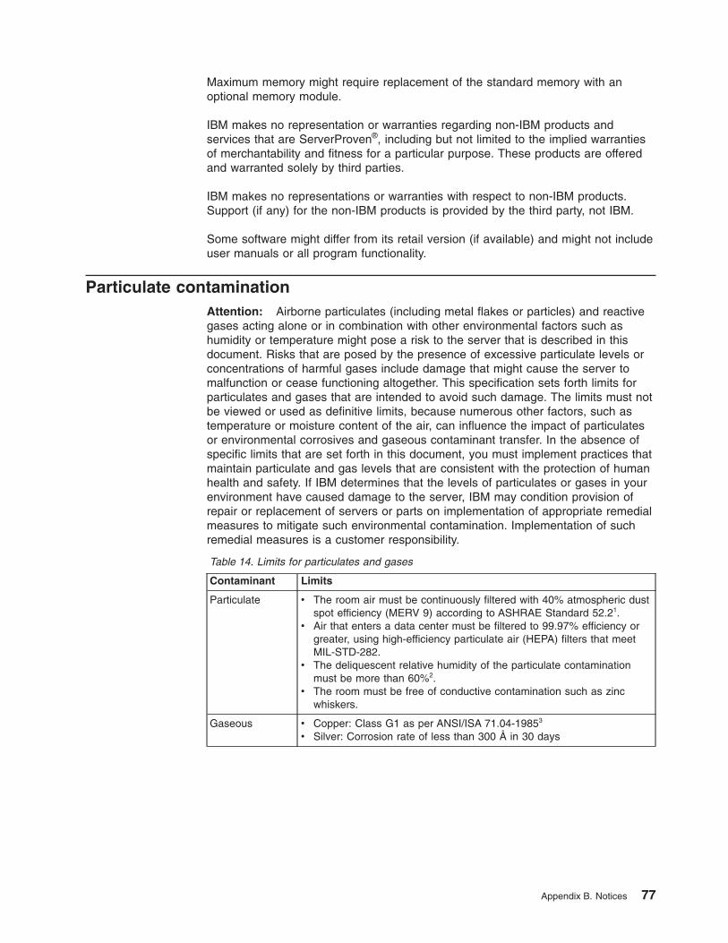
Maximum memory might require replacement of the standard memory with anoptional memory module.
IBM makes no representation or warranties regarding non-IBM products andservices that are ServerProven®, including but not limited to the implied warrantiesof merchantability and fitness for a particular purpose. These products are offeredand warranted solely by third parties.
IBM makes no representations or warranties with respect to non-IBM products.Support (if any) for the non-IBM products is provided by the third party, not IBM.
Some software might differ from its retail version (if available) and might not includeuser manuals or all program functionality.
Particulate contaminationAttention: Airborne particulates (including metal flakes or particles) and reactivegases acting alone or in combination with other environmental factors such ashumidity or temperature might pose a risk to the server that is described in thisdocument. Risks that are posed by the presence of excessive particulate levels orconcentrations of harmful gases include damage that might cause the server tomalfunction or cease functioning altogether. This specification sets forth limits forparticulates and gases that are intended to avoid such damage. The limits must notbe viewed or used as definitive limits, because numerous other factors, such astemperature or moisture content of the air, can influence the impact of particulatesor environmental corrosives and gaseous contaminant transfer. In the absence ofspecific limits that are set forth in this document, you must implement practices thatmaintain particulate and gas levels that are consistent with the protection of humanhealth and safety. If IBM determines that the levels of particulates or gases in yourenvironment have caused damage to the server, IBM may condition provision ofrepair or replacement of servers or parts on implementation of appropriate remedialmeasures to mitigate such environmental contamination. Implementation of suchremedial measures is a customer responsibility.
Table 14. Limits for particulates and gases
Contaminant Limits
Particulate v The room air must be continuously filtered with 40% atmospheric dustspot efficiency (MERV 9) according to ASHRAE Standard 52.21.
v Air that enters a data center must be filtered to 99.97% efficiency orgreater, using high-efficiency particulate air (HEPA) filters that meetMIL-STD-282.
v The deliquescent relative humidity of the particulate contaminationmust be more than 60%2.
v The room must be free of conductive contamination such as zincwhiskers.
Gaseous v Copper: Class G1 as per ANSI/ISA 71.04-19853
v Silver: Corrosion rate of less than 300 Å in 30 days
Appendix B. Notices 77

Table 14. Limits for particulates and gases (continued)
Contaminant Limits1 ASHRAE 52.2-2008 - Method of Testing General Ventilation Air-Cleaning Devices forRemoval Efficiency by Particle Size. Atlanta: American Society of Heating, Refrigerating andAir-Conditioning Engineers, Inc.
2 The deliquescent relative humidity of particulate contamination is the relative humidity atwhich the dust absorbs enough water to become wet and promote ionic conduction.
3 ANSI/ISA-71.04-1985. Environmental conditions for process measurement and controlsystems: Airborne contaminants. Instrument Society of America, Research Triangle Park,North Carolina, U.S.A.
Documentation formatThe publications for this product are in Adobe Portable Document Format (PDF)and should be compliant with accessibility standards. If you experience difficultieswhen you use the PDF files and want to request a Web-based format or accessiblePDF document for a publication, direct your mail to the following address:
Information DevelopmentIBM Corporation205/A0153039 E. Cornwallis RoadP.O. Box 12195Research Triangle Park, North Carolina 27709-2195U.S.A.
In the request, be sure to include the publication part number and title.
When you send information to IBM, you grant IBM a nonexclusive right to use ordistribute the information in any way it believes appropriate without incurring anyobligation to you.
Electronic emission notices
Federal Communications Commission (FCC) statementNote: This equipment has been tested and found to comply with the limits for aClass A digital device, pursuant to Part 15 of the FCC Rules. These limits aredesigned to provide reasonable protection against harmful interference when theequipment is operated in a commercial environment. This equipment generates,uses, and can radiate radio frequency energy and, if not installed and used inaccordance with the instruction manual, may cause harmful interference to radiocommunications. Operation of this equipment in a residential area is likely to causeharmful interference, in which case the user will be required to correct theinterference at his own expense.
Properly shielded and grounded cables and connectors must be used in order tomeet FCC emission limits. IBM is not responsible for any radio or televisioninterference caused by using other than recommended cables and connectors or byunauthorized changes or modifications to this equipment. Unauthorized changes ormodifications could void the user’s authority to operate the equipment.
78 System x3200 M2 Types 4367 and 4368: Installation Guide

This device complies with Part 15 of the FCC Rules. Operation is subject to thefollowing two conditions: (1) this device may not cause harmful interference, and (2)this device must accept any interference received, including interference that maycause undesired operation.
Industry Canada Class A emission compliance statementThis Class A digital apparatus complies with Canadian ICES-003.
Avis de conformité à la réglementation d’Industrie CanadaCet appareil numérique de la classe A est conforme à la norme NMB-003 duCanada.
Australia and New Zealand Class A statementAttention: This is a Class A product. In a domestic environment this product maycause radio interference in which case the user may be required to take adequatemeasures.
United Kingdom telecommunications safety requirementNotice to Customers
This apparatus is approved under approval number NS/G/1234/J/100003 for indirectconnection to public telecommunication systems in the United Kingdom.
European Union EMC Directive conformance statementThis product is in conformity with the protection requirements of EU CouncilDirective 2004/108/EC on the approximation of the laws of the Member Statesrelating to electromagnetic compatibility. IBM cannot accept responsibility for anyfailure to satisfy the protection requirements resulting from a nonrecommendedmodification of the product, including the fitting of non-IBM option cards.
This product has been tested and found to comply with the limits for Class AInformation Technology Equipment according to CISPR 22/European Standard EN55022. The limits for Class A equipment were derived for commercial and industrialenvironments to provide reasonable protection against interference with licensedcommunication equipment.
Attention: This is a Class A product. In a domestic environment this product maycause radio interference in which case the user may be required to take adequatemeasures.
European Community contact:IBM Technical RegulationsPascalstr. 100, Stuttgart, Germany 70569Telephone: 0049 (0)711 785 1176Fax: 0049 (0)711 785 1283E-mail: [email protected]
Appendix B. Notices 79

Taiwanese Class A warning statement
Germany Electromagnetic Compatibility DirectiveDeutschsprachiger EU Hinweis:
Hinweis für Geräte der Klasse A EU-Richtlinie zur ElektromagnetischenVerträglichkeit
Dieses Produkt entspricht den Schutzanforderungen der EU-Richtlinie 2004/108/EGzur Angleichung der Rechtsvorschriften über die elektromagnetische Verträglichkeitin den EU-Mitgliedsstaaten und hält die Grenzwerte der EN 55022 Klasse A ein.
Um dieses sicherzustellen, sind die Geräte wie in den Handbüchern beschrieben zuinstallieren und zu betreiben. Des Weiteren dürfen auch nur von der IBMempfohlene Kabel angeschlossen werden. IBM übernimmt keine Verantwortung fürdie Einhaltung der Schutzanforderungen, wenn das Produkt ohne Zustimmung derIBM verändert bzw. wenn Erweiterungskomponenten von Fremdherstellern ohneEmpfehlung der IBM gesteckt/eingebaut werden.
EN 55022 Klasse A Geräte müssen mit folgendem Warnhinweis versehen werden:“Warnung: Dieses ist eine Einrichtung der Klasse A. Diese Einrichtung kann imWohnbereich Funk-Störungen verursachen; in diesem Fall kann vom Betreiberverlangt werden, angemessene Maßnahmen zu ergreifen und dafür aufzukommen.”
Deutschland: Einhaltung des Gesetzes über dieelektromagnetische Verträglichkeit von GerätenDieses Produkt entspricht dem “Gesetz über die elektromagnetische Verträglichkeitvon Geräten (EMVG)”. Dies ist die Umsetzung der EU-Richtlinie 2004/108/EG inder Bundesrepublik Deutschland.
Zulassungsbescheinigung laut dem Deutschen Gesetz über dieelektromagnetische Verträglichkeit von Geräten (EMVG) (bzw. derEMC EG Richtlinie 2004/108/EG) für Geräte der Klasse ADieses Gerät ist berechtigt, in Übereinstimmung mit dem Deutschen EMVG dasEG-Konformitätszeichen - CE - zu führen. Verantwortlich für dieKonformitätserklärung des EMVG ist die IBM Deutschland GmbH, 70548 Stuttgart.
Generelle Informationen:
Das Gerät erfüllt die Schutzanforderungen nach EN 55024 und EN 55022Klasse A.
80 System x3200 M2 Types 4367 and 4368: Installation Guide
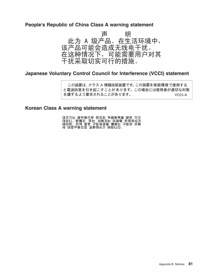
People's Republic of China Class A warning statement
Japanese Voluntary Control Council for Interference (VCCI) statement
Korean Class A warning statement
Appendix B. Notices 81

82 System x3200 M2 Types 4367 and 4368: Installation Guide

Index
AAC power LED 39accessible documentation 78acoustical noise emissions 6, 7adapter
installing 30requirements 28scanning order 29specifications 6support bracket 8
assistance, getting 73attention notices 5
Bbackplane 24, 25battery
safety viiibay identification 19bays 2 and 3, removable-media drives 20bays 4-7
hot-swap drives 24bays, filler panel 20, 22beep codes 47bezel
installing 32removing 13
Boot Menuusing 44
Broadcom NetXtreme Gigabit Ethernet Boot Agentenabling 44
Ccables
internal drives 28power 28rear connectors 35signal 28
caution statements 5CD drive
activity LED 38eject button 38installing 19problems 59specifications 6
CD or DVD driveinstalling 20
Class A electronic emission notice 78components, major 8configuration
updating 36Configuration/Setup Utility program 44configuring
the Ethernet controller 45the server 43
connectorcable 35Ethernet 39Ethernet Remote Supervisor Adapter II SlimLine 40external 38, 39parallel 39power cord 39serial 1 39serial 2 39Universal Serial Bus (USB) 38, 39video 39
contamination, particulate and gaseous 77controller
Ethernet 45controls and indicators 37cooling 7, 10cover
installing 34removing 12
Ddanger statements 5data rate, Ethernet controller 45diagnostic tools 47diskette drive
activity LED 38installing 19, 22problems 60specifications 6
diskette-eject button 38documentation CD 4documentation format 78drive
bay filler panel 20, 22bay identification 19cables 28hot-swap
installation 23support 19
installing 19removable-media 20, 22simple-swap 26
drive, hot-swapinstallation sequence 24
dual inline memory module (DIMM)connectors 17installing 17retaining clips 18
DVD driveactivity LED 38eject button 38problems 59
© Copyright IBM Corp. 2009 83

Eeject button
CD 38diskette 38DVD 38
electrical input 6, 7electromagnetic compatibility (EMC) shield 8, 20, 21,
22, 23electronic emission Class A notice 78enabling
Broadcom NetXtreme Gigabit Ethernet BootAgent 44
environment 6, 7error LED 71error messages, POST 48error symptoms
CD-ROM drive, DVD-ROM drive 59general 60hard disk drive 60intermittent 61keyboard 62keyboard, USB 71memory 63microprocessor 64mouse 62mouse, USB 71optional devices 67pointing device 62pointing device, USB 71power 68serial port 69software 70USB port 62, 71
Ethernetactivity LED 40connector 39high performance modes 45integrated on system board 45link status LED 40modes 45Remote Supervisor Adapter II SlimLine
connector 40teaming 45
Ethernet controllerconfiguring 45
Ethernet controller, configuring 45expansion slots 7, 29, 31external connectors 39
FFCC Class A notice 78features
server 6filler panel
hard disk drive bay 8removable-media drive bay 8, 21, 23removing 20, 22SAS 8SATA 8
Ggaseous contamination 77getting help 73
Hhandling static-sensitive devices 11hard disk drive
activity LED 37, 38hot-swap 23installing 19order of installation 26problems 60simple-swap 26status LED 38
hardware service and support 74heat output 6, 7help, getting 73hot-swap drive
backplaneactivity LED 38SAS IDs 25status LED 38
installation 23specifications 6
IIBM Support Line 74IDs for SAS hot-swap drives 25important notices 5indicators 37installation guidelines 9installation order
hard disk drives 26memory modules 15, 17
installingadapters 30CD or DVD drive 20cover 34hot-swap drives 23, 24internal drives 19lower bezel 33memory modules 15optional devices 9removable-media drives 19simple-swap drives 26tape drive 22upper bezel 32
intermittent problems 61internal
drives, installing 19
Kkeyboard problems 62, 71keys 3
to the serverlocation of 3
84 System x3200 M2 Types 4367 and 4368: Installation Guide

LLED
AC power 39LEDs
CD drive activity 38diskette drive activity 38DVD drive activity 38error 71Ethernet link status 40Ethernet transmit/receive activity 40hard disk drive activity 37hot-swap hard disk drive activity 38hot-swap hard disk drive status 38power-on 37system-error 37
locationof the server keys 3
lower bezelinstalling 33removing 13
LSI Configurationusing 46
LSI Configuration program 45
Mmajor components 8memory
installing 15problems 63specifications 6
memory moduleinstalling 17order of installation 15, 17specifications 7supported 15
microprocessorproblems 64specifications 6, 7
modes, Ethernet 45mouse problems 62, 71
Nnotes 5notes, important 76notices 75
electronic emission 78FCC, Class A 78
notices and statements 5
Oonline publications 1optional device
installation guidelines 9problems 67static-sensitive 11
optional devicesadapters 29, 30
optional devices (continued)connectors 39drives 19installing 9memory modules 15
order of installationhard disk drives 26memory modules 15, 17
Pparallel connector 39particulate contamination 77pointing-device problems 62, 71ports
Ethernet 39parallel 39serial 1 39serial 2 39Universal Serial Bus (USB) 38, 39, 71video 39
power control-button 37power problems 68power supply
specifications 7power-cord connector 39power-on LED 37power-on self-test (POST)
beep codes 47error messages 48
problemsCD-ROM, DVD-ROM drive 59diskette drive 60hard disk drive 60intermittent 61keyboard 62, 71memory 63microprocessor 64mouse 62, 71optional devices 67pointing device 62, 71power 68serial port 69software 70solving 47USB port 71
RRAID adapter
slot 29redundant array of independent disks (RAID)
adapter 25reliability, system 10removable-media drives, installing 19, 20removing
cover 12lower bezel 13upper bezel 14
retaining clips, dual inline memory module (DIMM) 18
Index 85

Ssafety information
handling static-sensitive devices 11introduction vimultilingual pointer vstatements viisystem reliability considerations 10when the server is on 11
scanning order for adapters 29serial 1 connector 39serial 2 connector 39Serial Advanced Technology Attachment (SATA)
hot-swap drives 23, 24simple-swap drives 26status LEDs for hot-swap drives 38
Serial Attached SCSI (SAS)activity LEDs for hot-swap drives 38backplane
activity LEDs for hot-swap drives 38description 24IDs for hot-swap drives 25status LEDs for hot-swap drives 38
hot-swap drives 23, 24status LEDs for hot-swap drives 38
serial port problems 69server
configuring 43features 6power features 40specifications 6
server keyslocation 3
ServerGuideCDs 1
simple-swap drives 26size 7software problems 70software service and support 74solving problems 47specifications 6starting
Configuration/Setup Utility program 44statements and notices 5static electricity 11static-sensitive devices, handling 11status LEDs 37support, web site 73system board
LEDs 71memory connectors 17
system reliability 10system specifications 6system-error LED 37
Ttape drive, installing 19telephone numbers 74temperature 6trademarks 75
troubleshooting chart 58two-piece bezel 13, 32
UUnited States electronic emission Class A notice 78United States FCC Class A notice 78Universal Serial Bus (USB)
connectorsfront 38rear 39
problems 62, 71upper bezel
installing 32removing 14
usingBoot Menu program 44LSI Configuration 46
utility programConfiguration/Setup 44
Utility programConfiguration/Setup 44
Vvideo
connector 39controller 7specifications 6
Wweb site
publication ordering 73support 73support line, telephone numbers 74
Web sitecompatible optional devices 3, 10, 15IBM eServer and System products 1IBM support 1ServerProven list 3, 10, 15
weight 6, 7
86 System x3200 M2 Types 4367 and 4368: Installation Guide


����
Part Number: 46M2038
Printed in USA
(1P) P/N: 46M2038