Embed Size (px)
Citation preview
Syst
em w
iring
MIS
3.6.1
System wiring MIS
The price of the control panel must be reduced! – but how?
In modern process manufacture, more and more control systems are being used.The control system must have the ability to communicate with the individual process peripherals, in other words control and measurement signals must be swapped back and forth. To achieve this, there are three distinctive ways ofwiring, either conventional wiring, system wiring (MIS) and field bus systems.
In conventional wiring the whole connection from I/O at PLC/DCC to interfacesection (series terminals, relays) are installed with single wires. In contrast ofthis, the system wiring MIS fits with only one cable. Murrelektronik system MIS offers all components, which are necessary for aneasy wiring to raise quality.
System wiring MISK
For connecting modules, there is a wide range of system cables available. The cablesare pre-wired with I/O card connector or other connector of the desired PLC type inlengths from 0.5…25 m. Already received connections from the manufacturer canbe pre-wired, too.This greatly simplifies the job of wiring a control panel.
I/O card connectors as well as SUB-D connectors can be plugged simply on tothe transfer moduleA circuit diagram no longer forms the basic layout for the control panel, the construction drawings are enoughThe control panel assembly time can at last be calculatedHigh quality panels, due to the reduction in possible fault sources
Transfer module built in the front door of a control panel
PLC/DDC
Fron
t con
necto
r
PLC/DDC
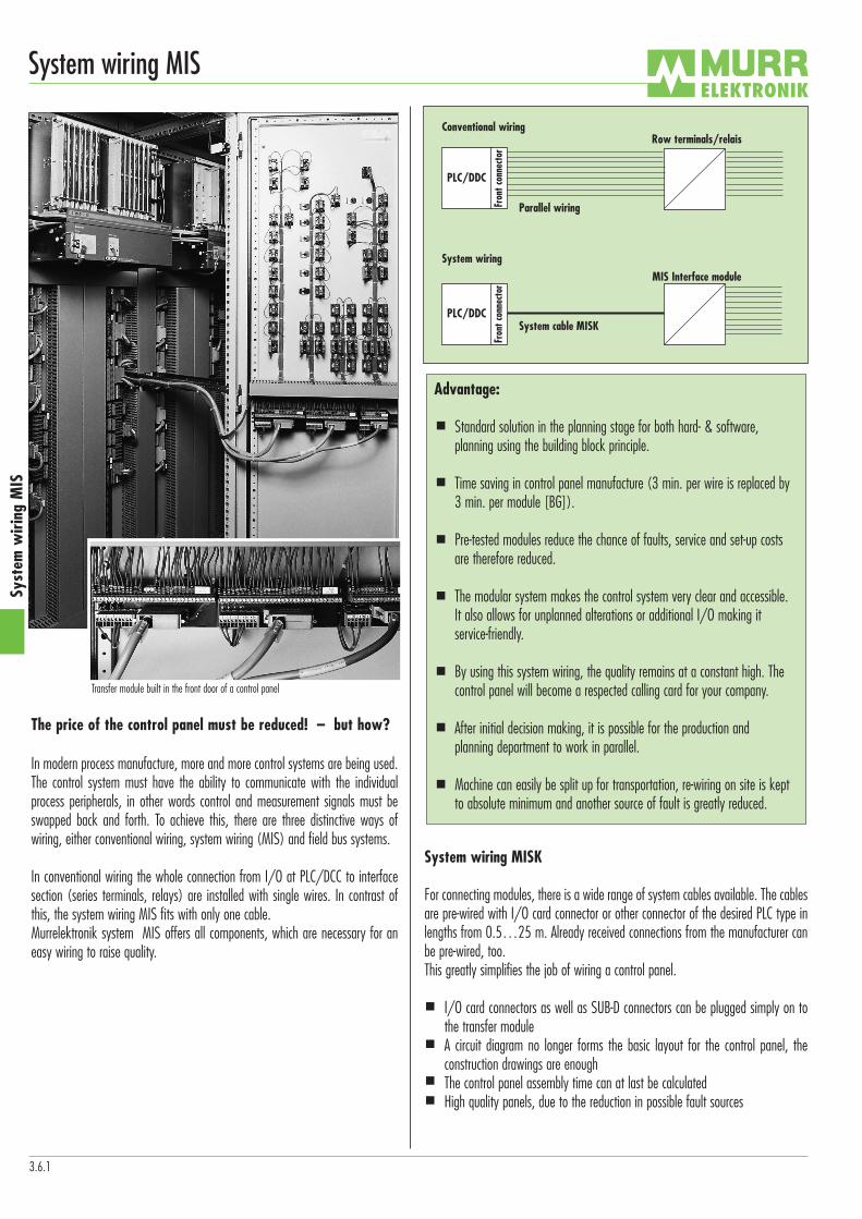
Conventional wiring
System wiring
Row terminals/relais
MIS Interface module
System cable MISK
Parallel wiring
Fron
t con
necto
r
Advantage:
Standard solution in the planning stage for both hard- & software, planning using the building block principle.
Time saving in control panel manufacture (3 min. per wire is replaced by3 min. per module [BG]).
Pre-tested modules reduce the chance of faults, service and set-up costsare therefore reduced.
The modular system makes the control system very clear and accessible.It also allows for unplanned alterations or additional I/O making it service-friendly.
By using this system wiring, the quality remains at a constant high. Thecontrol panel will become a respected calling card for your company.
After initial decision making, it is possible for the production and planning department to work in parallel.
Machine can easily be split up for transportation, re-wiring on site is keptto absolute minimum and another source of fault is greatly reduced.

Syst
em w
iring
MIS
3.6.2
System wiring MIS
Interface modules MIS
The most important difference in the product range is between active MISR-XX andpassive MISP-XX interface modules. In addition to this, is the difference between digital input/output (DI/DO) and analog input/output (AI/AO).
Passive interface module MISP-XX
The passive interface modules are most commonly used, when the PLC signal, irrespective of digital or analog, is transferred directly to the control panel terminals. The modules feature terminal blocks with a typical number of terminalsto that found on PLCs.
MISP – X DI/DO/AI/AOAnalog input/outputDigital input/outputNumber of channles per module (8-, 16-, 32-way)Murrelektronik Interface System Passive
Practical features:
Separate byte-wise voltage input for the I/O via the module Clearly visible separation due to the terminal layout of the module between thePLC side as well as the peripherals/field side
The power supply is via top mounted terminals, allowing the modules to besituated up against the cable channel (connections towards the controller)Via jumpers, it is possible to separate or join individual circuit loops. Moduleswith the “with opp. potential” option, also enable the byte-wise switching off by the opposite potential, irrespective of whether input or output modules. Labelling plate on each module.
Active interface module MISRX
The active interface modules are used when it is necessary to split the I/O galvani-cally from the field peripherals, to equalise power ratings within the system or in lar-ger process systems a clear change in power between the control level and the wiring.The module are constructed along similar lines as the passive modules. Module definition are made as follows:
MISR-X DI MISR-X DOactive input module active output moduledigital INPUT digital OUTPUT
Versions with relay or opto-couplers are available (voltage or power ratingdependent)8 or 16-channel optionsLED status indicatorsInternal suppression prevents inductive spikes from the relayMinimum space usageByte-wise PLC power input is possible
Interface modules
Active interface modules– galvanical separation of I/O and field peripherals– level and power adaption possible – assembly optional with relays or opto-coupler
page 3.6.13
System cable MISK– wide product range– complete wiring of I/O plug to MIS connector – customized cable length from 0.5…25 m
page 3.6.3
Passive interface modules– direct convertion of PLC signals onto terminals– analog and digital signals – 8-, 16- and 32-way modules
page 3.6.4

Syst
em w
iring
MIS
3.6.3
System wiring MIS
Technical dataConnector 1 x SUB-D 50, 60° 1 x SUB-D 25, 0° 2 x SUB-D 25, 0°Wire diameter in resp. 0.5… 9.5 m 1 x 44 x 0.25 mm2 * 1 x 24 x 0.25 mm2 2 x 24 x 0.25 mm2
to cable length 10.0…25.0 m 1 x 44 x 0.34 mm2 * 1 x 24 x 0.34 mm2 2 x 24 x 0.34 mm2
Fixing screw fixing UNC 4 - 40 screw fixing UNC 4 - 40 screw fixing UNC 4 - 40I/O connector each to PLC-type each to PLC-type each to PLC-type
MISK MISK MISK50-pole SUB-D connector 25-pole SUB-D connector 2 x 25-pole SUB-D connector
Technical dataConnector 15-pole SUB-D/14-pole front plug connector 1 x SUB-D 50, 60° 1 x SUB-D 25, 0°Wire diameter in resp. 0.5… 9.5 m 1 x 14 x 0.14 mm2 1 x 44 x 0.25 mm2 * 1 x 24 x 0.25 mm2
to cable length 10.0…25.0 m – 1 x 44 x 0.34 mm2 * 1 x 24 x 0.34 mm2
Fixing screw fix UNC 4 - 40/snap fix screw fixing UNC 4 - 40 screw fixing UNC 4 - 40I/O connector Adapter S5 135/155 – –
MISK MISK MISK15-pole SUB-D connector, 50-pole SUB-D connector 25-pole SUB-D connector14-pole Front plug connector with open ended wire with open ended wirewith Front plug adapter
NotesItem number for individual cable on request. * At the analog signal the cables are shielded.If your cable is not shown, please ask. We can deliver the desired cable in a short time.
General constructive layout of the system cable MISK
System cablewith front connector
System cablewith I/O connector

Syst
em w
iring
MIS
3.6.4
System wiring MIS
Notes1) Controller not included.
Ordering data Art.-No. Art.-No.MISP - 24DI/16DO 59211MISP - 16DO 59212MISP - 32DI/24DO basic module 546305MISP - 32DI/24DO expansion module 546303Technical data
Supply voltage 24 V DCSupply current each bit max. 1 AStatus indicator signals/supply yellow/green LED Connector 50-pole spring clamp terminals 2 x 34-pole spring clamp terminalsFixing screw fixing UNC 4 - 40Mounting method DIN-rail mounting to EN 60715 mounting at FANUC-controllersDimensions H x W x D 202.5 x 68 x 86 mm 140 x 82 x 66 mmTemperature range - 20…+ 60 °C
MISP-8AI/AO1) MISP-16AI/AO1)
for I/O Link for FSSBPassive interface modulesscrew terminals with bladecontacts
3-wire
for GE-FANUC controllers

3.6.5
Syst
em w
iring
MIS
Notes
Ordering data Art.-No.MISP - 32DI/DO screw terminal 596038
Technical dataSupply voltage 125 V AC/150 V DCSupply current each bit max. 3 AConnector 50-pole SUB-D female to DIN 41652Fixing screw fixing UNC 4 - 40Mounting method DIN-rail mounting to EN 60715Dimensions H x W x D 63 x 100 x 52 mmTemperature range - 20…+ 60 °C
Circuit diagram
System wiring MISMISP-32DI/DOscrew terminals
Passive interface modules
1-wire
200201
13 30 12 28 11 10 26 9 8 24 7 6 32 22 5 4 20 3 2 18 1 15 31 48 33 49 44 27 43 42 25 41 40 23 45 39 38 21 37 36 19 35 34 47
202203
204205
206207
210211
212213
214215
216217
220221
222223
224225
226227
230231
232233
234235
236237
+0 +1 +2 +3 M0 M1M2 M3
Art.-No. 596038

3.6.6
Syst
em w
iring
MIS
Notes
Ordering data Art.-No.MISP - 32DI/DO 596055
Technical dataSupply voltage 125 V AC/150 V DCSupply current each bit max. 3 AConnector 50-pole SUB-D female to DIN 41652Fixing screw fixing UNC 4 - 40Mounting method DIN-rail mounting to EN 60715Dimensions H x W x D 86 x 180 x 75 mmTemperature range - 20…+ 60 °C
Circuit diagram
System wiring MISMISP-32DI/DOscrew terminals with blade contacts
Passive interface modules
1-wire
200201
13 30 12 28 11 10 26 9 8 24 7 6 32 22 5 4 20 3 2 18 1 15 31 48 33 49 44 27 43 42 25 41 40 23 45 39 38 21 37 36 19 35 34 47
202203
204205
206207
210211
212213
214215
216217
220221
222223
224225
226227
230231
232233
234235
236237
+0 +1 +2 +3 M0 M1M2 M3M+

3.6.7
Syst
em w
iring
MIS
System wiring MIS
Ordering data Art.-No.MISP - 32DI/DO 596035
Technical dataSupply voltage max. 125 V AC, 150 V DCSupply current each bit max. 3 AConnector 50-pole SUB-D female to DIN 41652Fixing screw fixing UNC 4 - 40Mounting method DIN-rail mounting to EN 60715Dimensions H x W x D 63 x 165 x 48 mmTemperature range - 20…+ 60 °C
Notes
Circuit diagram
MISP-32DI/DOscrew terminals
Passive interface modules
2-wire
(Byte 0) Jumper layout on the module
24V0
+0 +1 +2 +3
24V1 24V324V2 GND3GND2GND1GND0
(Byte 1) (Byte 2) (Byte 3)
+0 +1 +3+2 M3M2M1M0
B0 M0 B1 M1 B2 M2 B3 M3
200 202 204 206 210 212 214 216201 203 205 207 211 213 215 217
100 102 104 106 110 112 114 116101 103 105 107 111 113 115 117
220 222 224 226 230 232 234 236221 223 225 227 231 233 235 237
120 122 124 126 130 132 134 136121 123 125 127 131 133 135 137
13 30 12 28 11 10 26 9 8 24 7 6 32 22 5 4 20 3 2 18 1 15 31 48 33 49 44 27 43 42 25 41 40 23 45 39 38 21 37 36 19 35 34 47
+ +0 +1 +2 +3 M M0 M1 M2 M3
+0 +1 +2 +3 M0B0
M1 M2 M3B1 B2 B3

Syst
em w
iring
MIS
Notes
Ordering data Art.-No.MISP - 32DI/DO 596095
Technical dataSupply voltage max. 125 V AC, 150 V DCSupply current each bit max. 3 AConnector 50-pole SUB-D female to DIN 41652Fixing screw fixing UNC 4 - 40Mounting method DIN-rail mounting to EN 60715Dimensions H x W x D 63 x 95 x 48 mmTemperature range - 20…+ 60 °C
Circuit diagram
MISP-32DI/DOscrew terminals with blade contacts
Passive interface modules
2-wire
(Byte 0) Jumper layout on the module
24V0
+0 +1 +2 +3
24V1 24V324V2 GND3GND2GND1GND0
(Byte 1) (Byte 2) (Byte 3)
+0 +1 +3+2 M3M2M1M0
B0 M0 B1 M1 B2 M2 B3 M3
200 202 204 206 210 212 214 216201 203 205 207 211 213 215 217
100 102 104 106 110 112 114 116101 103 105 107 111 113 115 117
220 222 224 226 230 232 234 236221 223 225 227 231 233 235 237
120 122 124 126 130 132 134 136121 123 125 127 131 133 135 137
13 30 12 28 11 10 26 9 8 24 7 6 32 22 5 4 20 3 2 18 1 15 31 48 33 49 44 27 43 42 25 41 40 23 45 39 38 21 37 36 19 35 34 47
+ +0 +1 +2 +3 M M0 M1 M2 M3
+0 +1 +2 +3 M0B0
M1 M2 M3B1 B2 B3
3.6.8
System wiring MIS

3.6.9
Syst
em w
iring
MIS
System wiring MIS
Notes
Circuit diagram
MISP-16DI/DO MISP-8DI/DOscrew terminals screw terminals
Passive interface modules
2-wire
(Byte 0) Jumper layout on the module
24V
+0 +1
24V0 24V124V0
(Byte 1)
+ +0
GND GND0 GND1GND0
+0 +1 M0M
B0 M0 B1 M1
M1M0
100 102 104 106101 103 105 107
200 202 204 206201 203 205 207
110 112 114 116111 113 115 117
210 212 214 216211 213 215 217
12 25 6 19 23 10 22 9 21 8 20 7 11 24 17 4 16 3 15 2 14 1 5 18
+ +0 +1 M M0M1
+0 +1+B0
M1MB1
M0
100 102 104 106101 103 105 107
200 202 204 206201 203 205 207
13 14 10 11 1 2 3 4 5 6 7 8
+0+ M M0
+0B0 M
12 9
Ordering data Art.-No. Art.-No.MISP - 16DI/DO 596054MISP - 8DI/DO 596075Technical data
Supply voltage max. 125 V AC, 150 V DCSupply current each bit max. 3 AConnector 25-pole SUB-D female to DIN 41642 15-pole SUB-D female to DIN 41642Fixing screw fixing UNC 4 - 40Mounting method DIN-rail mounting to EN 60715Dimensions H x W x D 63 x 95 x 48 mm 63 x 75 x 48 mmTemperature range - 20…+ 60 °C
Art.-No. 596054
Art.-No. 596075

Notes
Ordering data Art.-No.MISP - 32DI/DO 596056
Technical dataSupply voltage max. 125 V AC, 150 V DCSupply current each bit max. 3 AConnector 50-pole SUB-D female to DIN 41652Fixing screw fixing UNC 4 - 40Mounting method DIN-rail mounting to EN 60715Dimensions H x W x D 86 x 180 x 75 mmTemperature range - 20…+ 60 °C
Circuit diagram
System wiring MISMISP-32DI/DOscrew terminals
Passive interface modules
3-wire
200 202 204 206 210 212 214 216201 203 205 207 211 213 215 217
100 102 104 106 110 112 114 116101 103 105 107 111 113 115 117
220 222 224 226 230 232 234 236221 223 225 227 231 233 235 237
120 122 124 126 130 132 134 136121 123 125 127 131 133 135 137
300 302 304 306 310 312 314 316301 303 305 307 311 313 315 317
320 322 324 326 330 332 334 336321 323 325 327 331 333 335 337
13 30 12 28 11 10 26 9 8 24 7 6 32 22 5 4 20 3 2 18 1 15 31 48 33 49 44 27 43 42 25 41 40 23 45 39 38 21 37 36 19 35 34 47
+ +0 +1 +2 +3 M M0M1M2 M3
+0 +1 +2 +3 M0B0
M1 M2 M3B1 B2 B3
P P
(Byte 0) Jumper layout on the module
24V0
+0 +1 +2 +3
24V1 24V324V2 GND3GND2GND1GND0
(Byte 1) (Byte 2) (Byte 3)
+0 +1 +3+2 M3M2M1M0
B0 M0 B1 M1 B2 M2 B3 M3
3.6.10
Syst
em w
iring
MIS

3.6.11
Syst
em w
iring
MIS
Notes
Ordering data Art.-No. Art.-No.MISP - 8AI/AO – ABB 596053MISP - 8AI/AO 596057Technical data
Supply voltage max. 125 V AC, 150 V DC max. 30 V DCSupply current each bit max. 3 A max. 0.5 AConnector 9-pole SUB-D female to DIN 41652 25-pole SUB-D female to DIN 41652Fixing screw fixing UNC 4 - 40 screw fixing UNC 4 - 40Mounting method DIN-rail mounting to EN 60715 DIN-rail mounting to EN 60715Dimensions H x W x D 75 x 70 x 85 mm 90 x 86 x 75 mmTemperature range - 20…+ 60 °C
Circuit diagram
MISP-8AI/AO MISP-8AI/AOscrew terminals screw terminalsspecified for Allen Bradley
Passives interface modules
3-wire
System wiring MIS
SUB-DGehäuse
25 13 24 12 23 11 22 10 21 9 20 8 19 7 18 6 17 5 16 4 15 3 2 1 14 F+ F+ – –F - F -+ +
BR 1
BR 2
1 3 5 7 9 11 13 15 17 19
2 6 8 10 12 14 16 18 204
1 62 73 84 95
––
200 205201 206202 207203 204
100 105101 106102 107103 104
BR 1, BR 2 - Plug link
Art.-No. 596057
Art.-No. 596053SUB-DHousing
Housing

Notes
Ordering data Art.-No. Art.-No.MISP - 8AI/AO 596065MISP - 16AI/AO 596066Technical data
Supply voltage max. 50 V AC/DCSupply current each bit max. 1 AConnector 25-pole SUB-D female to DIN 41652 50-pole SUB-D female to DIN 41652Fixing screw fixing UNC 4 - 40Mounting method DIN-rail mounting to EN 60715Dimensions H x W x D 86 x 135 x 75 mm 86 x 225 x 75 mmTemperature range - 20…+ 60 °C
Circuit diagram
MISP-8AI/AO MISP-16AI/AOscrew terminals with blade contact screw terminals with blade contact
Passive interface modules
2-wire
4-wire
System wiring MIS
Art.-No. 59606525SUB-D
Gehäuse24 13 23 12 22 11 21 10 20 9 19 8 18 7 17 6 3 2 1 14 + + +F -F – –
1 2 3 4 5 6 7 8 9 10 11 12 13 14 15 16
Art.-No. 596066SUB-DGehäuse
11 10 26 9
1 2 3 4
8 24 7 6
5 6 7 8
22 5 4 20
9 10 11 12
3 2 18 1
13 14 15 16
44 27 43 42
17 18 19 20
25 41 40 23
21 22 23 24
39 38 21 37
25 26 27 28
36 19 35 34
29 30 31 32
+F -F -L +L +L +K -K30 17 16 144629
3.6.12
Syst
em w
iring
MIS
Housing
Housing

3.6.13
Syst
em w
iring
MIS
System wiring MIS
NotesOpto-coupler and other voltages on request. 1) Controller not included.* Safe separation to DIN VDE 0106 part 101. Root doubled
Ordering data Art.-No.MISR - 24 DI/16 DO *546298
Technical dataInput voltage (PLC output) 24 V DC Connection current each bit approx. 14 mAStatus indicator LED yellow/greenSwitched voltage (field side) 250 V AC/DCSwitched current max. 3 AMin. load current 10 mAContact/contact material N/O contacts/Ag Sn O2Switch on, drop off and bounce time 8/ 20/ 2 msMechanical relay (replacable) Art.-No. 61513Semiconductor (replacable) –Mounting method DIN-rail mounting to EN 60715Dimensions H x W x D 337 x 68 x 86 mmTemperature range - 20…+ 60 °C
MISR-24DI/16DO 1)
with safe separation Active interface module
3-wire
for GEFANUC controllers

3.6.14
Syst
em w
iring
MIS
System wiring MIS
LED LED
N00 N01 N02 N03 L0 100 101 102 103 104 105 106 107 L00 L1 110 111 112 113 114 115 116 117 L10
N10 N11 N12 N13 200 201 202 203 204 205 206 207 210 211 212 213 214 215 216 217
723 10 22 9 21 8 20 117 4 16 3 15 2 145 18 12 25 11 24 6 19
+0 +00 +1 +10 M0 M00 M1 M10
Opto-coupler and other voltages on request.
Ordering data Art.-No. Art.-No.MISR - 16DI 596036MISR - 8DI 596074Technical data
Input voltage (field side) 230 V AC + 10 % – 15 %Connection current each bit max. 10 mAStatus indicator yellow LED Switched voltage (PLC input) 24 V DCSwitched current max. 1 AMin.load current 1 mAConnector 25-pole SUB-D female to DIN 41652 15-pole SUB-D female to DIN 41652Contact material Ag + Au platedSwitch on, drop off and bounce time 5/ 5/ 1 msRemovable single relay HY 1NIL - 24 V Matsushita, alternative G 5 V - 1 - 24 V Omron
(Art.-No. 616019 as accessories)Fixing screw fixing UNC 4 - 40Mounting method DIN-rail mounting to EN 60715Temperature range - 20…+ 60 °CDimensions H x W x D 86 x 157 x 69 mm 86 x 90 x 75 mmNotes
Circuit diagram
MISR-16DI MISR-8DIActive interface module
Input relay
Art.-No. 596036
BR1 BR2

3.6.15
Syst
em w
iring
MIS
LED LED
N00 N01 N02 N03 L0 100 101 102 103 104 105 106 107 L00 L1 110 111 112 113 114 115 116 117 L10
N10 N11 N12 N13 200 201 202 203 204 205 206 207 210 211 212 213 214 215 216 217
723 10 22 9 21 8 20 117 4 16 3 15 2 145 18 12 25 11 24 6 19
+0 +00 +1 +10 M0 M00 M1 M10
* Safe separation to DIN VDE 0106 part 101. Opto-coupler and other voltages on request.
Ordering data Art.-No. Art.-No.MISR - 16DI * 596048MISR - 16DI 596079
Technical dataInput voltage (field side) 24 V DC ± 10 % 60 V DC ± 10 %Connection current each bit max. 10 mAStatus indicator yellow LED Switched voltage (PLC input) 24 V DCSwitched current max. 1 AMin.load current 1 mAConnector 25-pole SUB-D female to DIN 41652Contact material Ag + Au platedSwitch on, drop off and bounce time 5/ 5/ 1 msRemovable single relay HY 1NIL - 24 V Matsushita, alternative G 5 V - 1 - 24 V Omron
(Art.-No. 616019 as accessories) Fixing screw fixing UNC 4 - 40Mounting method DIN-rail mounting to EN 60715Temperature range - 20…+ 60 °CDimensions H x W x D 86 x 157 x 69 mmNotes
Circuit diagram
MISR-16DIActive interface module
Input relay
BR1 BR2
System wiring MIS

3.6.16
Syst
em w
iring
MIS
101
1
102 104 111
2
112 114 121
3
122 124 131
4
132 134 141
5
142 144 151
6
152 154 161
7
162 164 171
8
172 174
14
M +MO
111091312
+ 0
NotesOpto-coupler and other voltages on request.* Safe separation to DIN VDE 0106 part 101. Root doubled
Ordering data Art.-No. Art.-No.MISR - 8DO * 596073MISSNR - 8DO 596133
Technical dataInput voltage (PLC output) 24 V DC ± 10 %Connection current each bit max. 30 mA approx. 11 mAStatus indicator red LED green LED Switched voltage (field side) 250 V AC/150 V DC 250 V AC/DCSwitched current max. 5 A max. 6 AMin.load current 100 mA 10 mAConnector 15-pole SUB-D female to DIN 41652Contact/contact material C/O contacts/AgNi hv C/O contacts/AgSn O2Switch on, drop off and bounce time 10/ 10/ 2 ms 10/ 15/ 1.5 msMechanical relay (replacable) RYS 01 024 Schrack, alternative M15FBH 0018 24 V DC FEME SNR relays, 24 V DC switched current max. 6 A, Art.-No. 61513Semiconductor (replacable) – ELR semiconductor, 24 V DC switched current max. 2 A, Art.-No. 61506Fixing screw fixing UNC 4 - 40Mounting method DIN-rail mounting to EN 60715Dimensions H x W x D 86 x 112.5 x 75 mm 86 x 67.5 x 75 mmTemperature range - 20…+ 60 °C
Circuit diagram
MISR-8DO MISSNR-8DOwith safe separation
Active interface module
Output relay
Art.-No. 596073
1
101 102104
2
111 112114
3
121 122124
4
131 132134
5
141 142144
6
151 152154
7
161 162164
8
171 172174
14
M +MO
111091312
+ 0
Art.-No. 596133
System wiring MIS

3.6.17
Syst
em w
iring
MIS
101 104102 111
112114
121 124122 131
132134
141 144142 151
152154
161 164162 171
172174
201 204202 211
212214
221 224222 231
232234
241 244242
261 264262251
252254 271
272274
23 10 22 9 21 8 20 7 17 4 16 3 15 2 14 1
5 18 11 24 6 19 12 25 +0 +0 +1 +1 M0 M0 M1 M1
BR1
BR2
NotesOpto-coupler and other voltages on request.* Safe separation to DIN VDE 0106 part 101. Root doubled
Ordering data Art.-No. Art.-No. Art.-No.MISR - 16DO 596037MISRS - 16DO 596109MISR - 16DO * 596058
Technical dataInput voltage (PLC output) 24 V DC ± 10 %Connection current each bit max. 30 mAStatus indicator red LED Switched voltage (field side) 250 V AC/300 V DC 250 V AC/150 V DCSwitched current max. 5 A 3 A max. 5 AMin.load current 100 mA 1 mA 100 mAConnector 25-pole SUB-D female to DIN 41652 Contact/contact material C/O contacts/Ag hv N/O contacts/Ag hv C/O contacts/AgNi hvSwitch on, drop off and bounce time 10/ 10/ 2 msRemovable single relay V 23 057-B0006-A201 Tyco NYP-24W-K Takamisawa RYS 01 024 Schrack, alternative M15FBH 0018
(Art.-No. 61410 as accessories) – 24 V DC FEMEFixing screw fixing UNC 4 - 40Mounting method DIN-rail mounting to EN 60715Dimensions H x W x D 86 x 180 x 75 mm 63 x 115 x 48 mm 86 x 225 x 75 mmTemperature range - 20…+ 60 °C
Circuit diagram
MISR-16DO MISRS-16DO MISR-16DOwith safe separation
Active interface module
Output relay
Art.-No. 596037
101 104111 114
121 124131 134
141 144151 154
161 164171 174
201 204211 214
221 224231 234
241 244 261 264251 254 271 274
23 10 22 9 21 8 20 7 17 4 16 3 15 2 14 1
5 18 11 24 6 19 12 25 +0 +0 +1 +1 M0 M0 M1 M1
BR1
BR2
Art.-No. 596109
image: 596109image: 596037
System wiring MIS