Embed Size (px)
Citation preview
SYSTEM SUMMARY
Wind Tunnel Acoustic Test SystemReduction of noise emissions is a critical technology for aircraftmanufacturers, so various analytical, empirical and numerical toolsexist to help in the design of quieter aircraft.
Given the complexity of the noise source mechanisms,aeroacoustic measurements in wind tunnels are used to providevital contributions to the understanding and mitigation of thesephenomena.
The Brüel & Kjær Wind Tunnel Acoustic Test System accuratelyperforms all the tasks needed for aircraft acoustic scale modeltesting.
The system is based on Brüel & Kjær's standard, commercial-off-the-shelf (COTS) products that cover the entire measurementchain of transducer, data acquisition, analysis and reporting.
Noise Measurements and Measurement Challenges in Wind Tunnels
Noise pollution, fuel efficiency, and low carbon emissions are key drivers for 21st century aircraft designs.The combination of increasingly strict aircraft noise certification criteria, aircraft-noise-related landing fees,and interior-noise guarantees keeps the pressure on airframers, and engine, and nacelle manufacturers, toensure that the development of noise-reduction technology remains centre stage.
Wind tunnels are traditionally used to develop and validate aerodynamic designs at much reduced costwhen compared with full-scale flight testing. These facilities can also be used for aeroacousticmeasurements of aircraft noise sources and their directivities; both for the validation of prediction methodsand for the investigation of the acoustic impact of noise-reduction treatments.
Airframe noise research is generally focused on the components on an airframe that produce noise: flaps,landing gear, and high-lift leading- and trailing-edge devices, etc. Other areas of growing aeroacousticinterest include open rotors and cavity acoustics.
Open-circuit vs. Closed-circuit Wind TunnelsBoth open-circuit, anechoic wind tunnels, and closed-circuit wind tunnels are used for aerodynamic andaeroacoustic studies of various flow-induced noise phenomena. The choice of test facility is driven primarilyby the type of application, the design speed, and the desired model scale. The preferred set up is alsoinfluenced by the priority for aerodynamic or noise measurements. Due to the issues around maintainingReynolds number (the ratio of inertial to viscous forces), wind tunnels can also be pressurized and run atcryogenic temperatures. A further challenge is that it is often necessary to work at very high acousticfrequencies, particularly for small scale models. As the frequency of the noise created using a scale model isinversely proportional to the size of the model, this also challenges the capabilities of the acoustic dataacquisition and analysis system.
Brüel & Kjær can supply the instrumentation to suit all aeroacoustic testing requirements. We can also passon years of experience with multiple microphone measurements and optimised microphone installations,which can help you to choose the most effective, and cost-efficient, test solution.
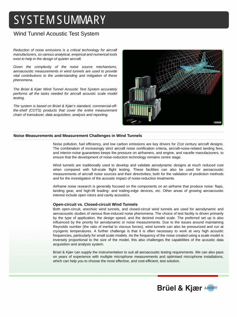
Wind Tunnel Acoustic Test system
The Brüel & Kjær Wind Tunnel Acoustic Test System is a dedicated solution, integrating and optimising thedifferent inherent features of Brüel & Kjær COTS products. These products encompass the wholemeasurement chain, and they are optimised for the specific issues faced with wind tunnel test applications.Furthermore, dedicated streamlined workflow software ensures that all required tasks and operations forsetup, calibration, recording, analysis and reporting are performed with maximum reliability and efficiency.
A schematic is provided in Fig. 1
Fig. 1 Wind tunnel acoustic test system architecture
System Components
The system typically consists of:• The necessary number of microphones, preamplifiers, and cables to support the desired noise
measurements. Examples are:– 1/4″ Pressure-field microphones with a flat frequency response up to 6 atm., and useable down to
– 40° C– Surface microphones and high SPL microphones– Preamplifiers with a short body design for mounting in confined spaces– TEDS, CIC and VIC capabilities– Beamforming phased-array microphones– Cables at desired lengths
• LAN-XI Data Acquisition Modules. Mounted in racks, or distributed individually:– Sampling frequencies up to 524 kHz – Tight phase matching between channels– Changeable front panels with signal conditioning to suit different inputs, for example, classical/CCLD
microphones, CCLD/charge accelerometers, Kulite® pressure sensors– Can safely operate under high/low static pressures at relatively high temperatures – from 0.4 bar
(30°C) to 6 bar (50°C)• An Acquisition Workstation installed with:
– Data Recorder software– Software for real-time FFT, CPB (1/n-octave) and Overall Analysis– Software for post-processing of recorded data– Workflow-oriented application software, to guide you through the data acquisition and analysis
operations.
140007
Microphones- High static pressure- Cryogenic- Surface or conventional- Arrays
Central Workstation- High data transfer- Workflow driven application software- Data recording- Post-analysis
Interface to Wind Tunnel Control- Remote control of the data acquisition process- Seamlessly transfer process-data during recording
Data Acquisition- Distributed and/or in frame- High static pressure- High channel counts- High sampling frequency- High channel phase match- High dynamic range
PTP Switch- High channel phase match
Remote Display- Monitoring signals during recording
2
• PTP (Precision Time Protocol) Enabled LAN– PTP LAN switches to maintain a high phase match on all channels even in LAN networks with multiple
switching layers• One or more Remote Monitoring Stations
– At remote monitoring stations you can select some or all of the channels to monitor in real-time duringdata recording
Data Recording and System Performance
The prime objective of the wind tunnel application is to get quality data recorded without any testcomplications. Ease-of-use and up-time are essential system parameters.
Spreadsheet SetupThe system uses a spreadsheet file to set up the entire test. This gives very fast load and re-load of the testsystem. It also allows the test engineer to configure multiple tests in the office before the test, without havingaccess to the test system.
Workflow-oriented OperationThe application is organised with a sequence of tabs providing workflow guidance through the variousstages of setup, calibration, recording, analysis, data management and reporting.
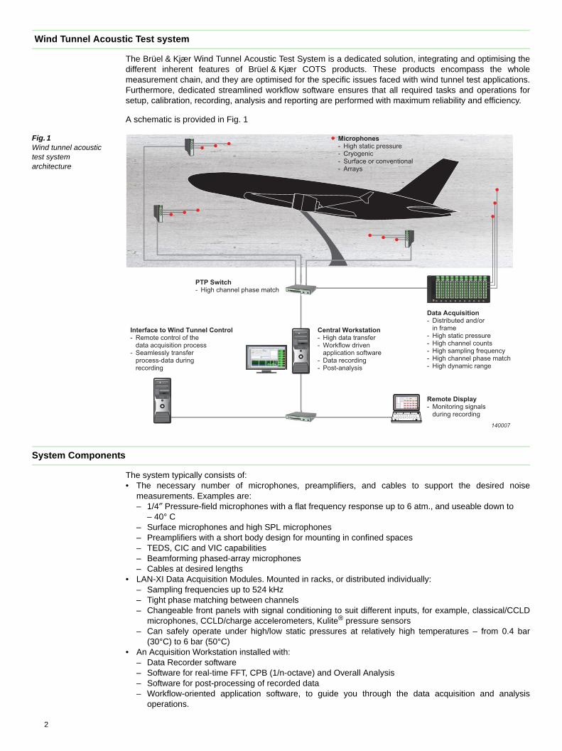
Data RecordingThe system user-interface provides no-nonsense access to vital test system information and recordercontrol, see Fig. 2.
Fig. 2 The Wind Tunnel Acoustic Test System user-interface. Top-left, the recorder control. Right, LAN-XI module status (temperature). Bottom, the overall level from each of the measurement channels. (Note that this UI can be customised to suit your specific application needs)
Remote Monitoring During RecordingDuring the wind tunnel test, acoustic data is recorded to disk for downstream analysis. During the actualrecording, it can be a benefit to monitor certain individual acquisition channels, supplying instant feedbackon test quality and on the validity of data.
Test data can be analysed in real-time via a remote monitoring station providing real-time level, time, FFTand/or octave analysis. Process data from the wind tunnel control system can also be displayed, and a set ofacoustic channels listened to via headphones, see Fig. 3.
Self-testA data acquisition digital/analogue self-test function gives you a powerful tool to make on-site verificationand/or calibration. This means that it is not necessary to ship equipment to an external calibration facility,with the ensuing down time of the test facility.
3
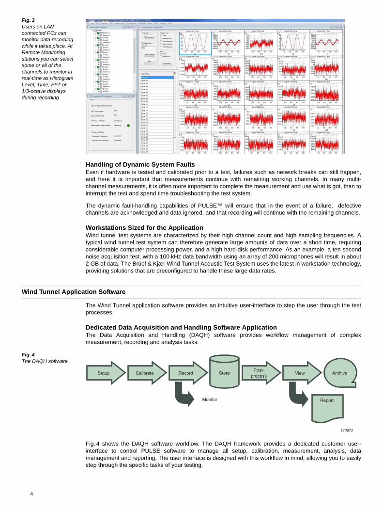
Fig. 3 Users on LAN- connected PCs can monitor data recording while it takes place. At Remote Monitoring stations you can select some or all of the channels to monitor in real-time as Histogram Level, Time, FFT or 1/3-octave displays during recording
Handling of Dynamic System FaultsEven if hardware is tested and calibrated prior to a test, failures such as network breaks can still happen,and here it is important that measurements continue with remaining working channels. In many multi-channel measurements, it is often more important to complete the measurement and use what is got, than tointerrupt the test and spend time troubleshooting the test system.
The dynamic fault-handling capabilities of PULSE™ will ensure that in the event of a failure, defectivechannels are acknowledged and data ignored, and that recording will continue with the remaining channels.
Workstations Sized for the ApplicationWind tunnel test systems are characterized by their high channel count and high sampling frequencies. Atypical wind tunnel test system can therefore generate large amounts of data over a short time, requiringconsiderable computer processing power, and a high hard-disk performance. As an example, a ten secondnoise acquisition test, with a 100 kHz data bandwidth using an array of 200 microphones will result in about2 GB of data. The Brüel & Kjær Wind Tunnel Acoustic Test System uses the latest in workstation technology,providing solutions that are preconfigured to handle these large data rates.
Wind Tunnel Application Software
The Wind Tunnel application software provides an intuitive user-interface to step the user through the testprocesses.
Dedicated Data Acquisition and Handling Software ApplicationThe Data Acquisition and Handling (DAQH) software provides workflow management of complexmeasurement, recording and analysis tasks.
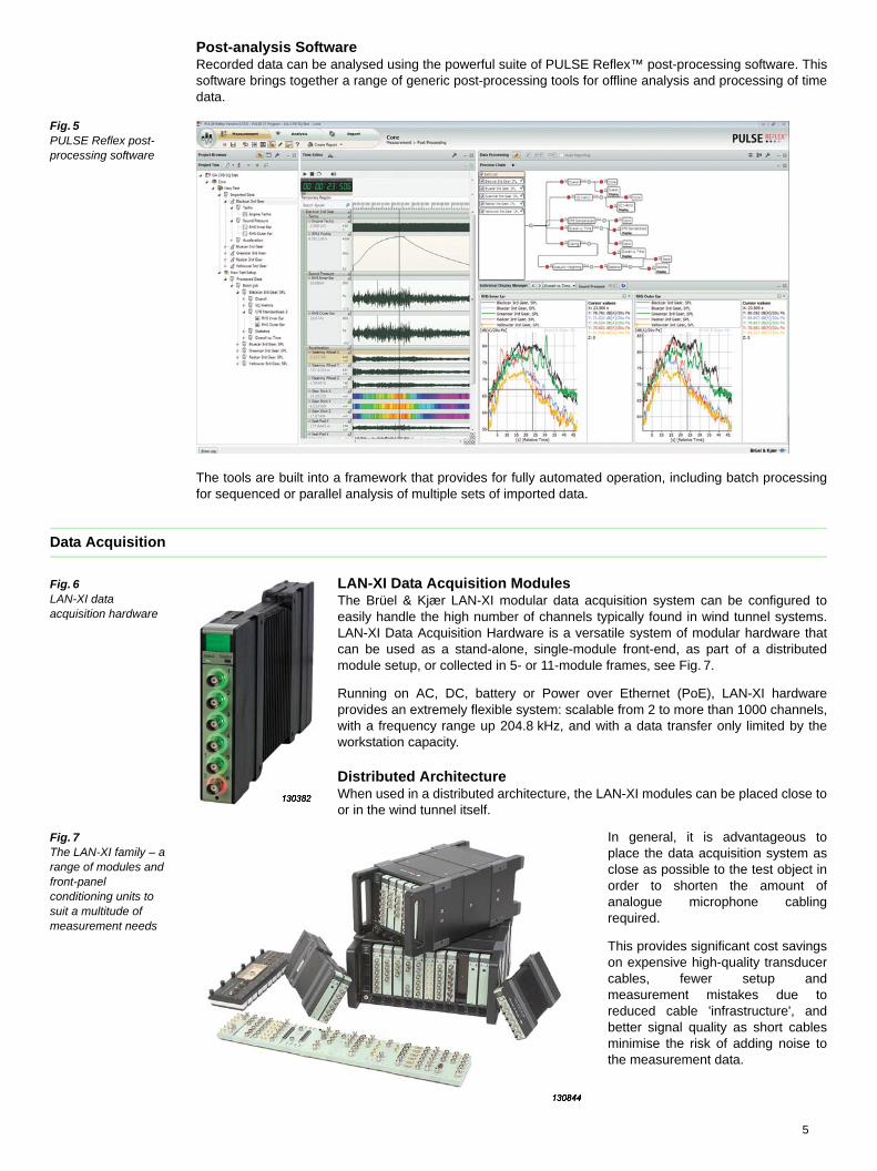
Fig. 4 The DAQH software
Fig. 4 shows the DAQH software workflow. The DAQH framework provides a dedicated customer user-interface to control PULSE software to manage all setup, calibration, measurement, analysis, datamanagement and reporting. The user interface is designed with this workflow in mind, allowing you to easilystep through the specific tasks of your testing.
Setup Calibrate Record Store
Monitor
Post-process View Archive
Report
130572
4
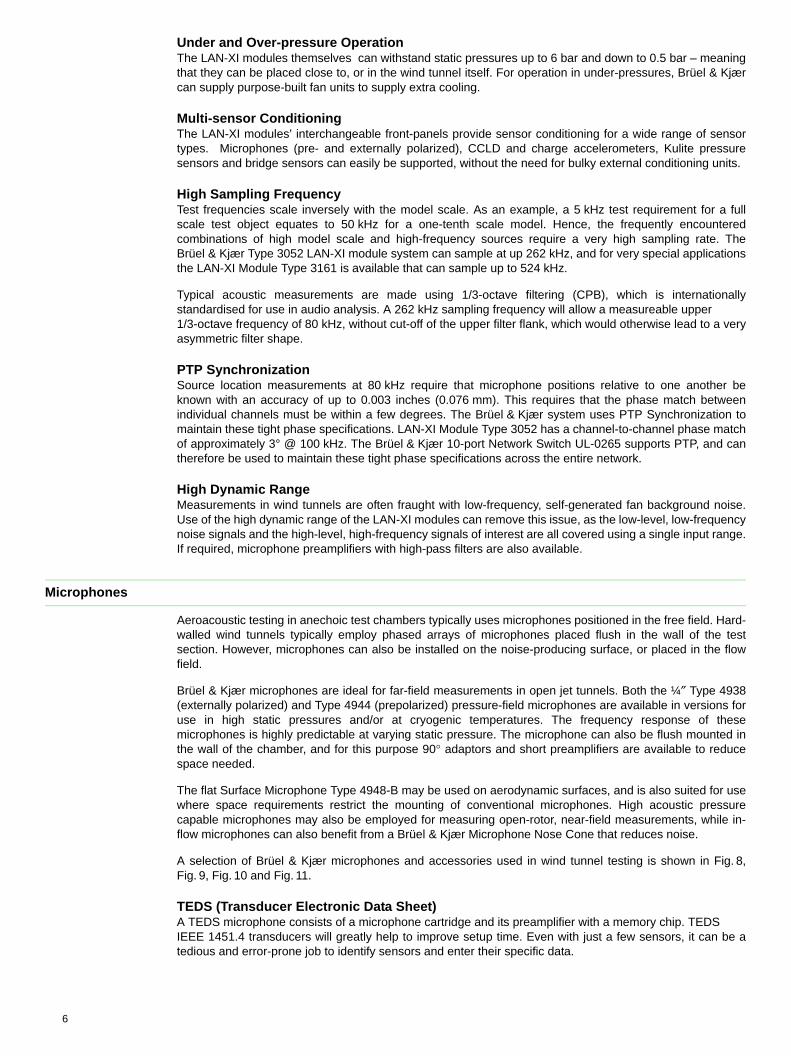
Post-analysis SoftwareRecorded data can be analysed using the powerful suite of PULSE Reflex™ post-processing software. Thissoftware brings together a range of generic post-processing tools for offline analysis and processing of timedata.
Fig. 5 PULSE Reflex post-processing software
The tools are built into a framework that provides for fully automated operation, including batch processingfor sequenced or parallel analysis of multiple sets of imported data.
Data Acquisition
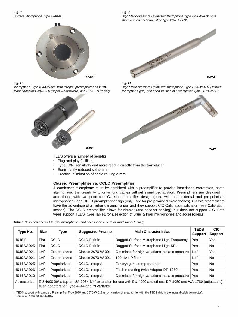
Fig. 6LAN-XI data acquisition hardware
LAN-XI Data Acquisition ModulesThe Brüel & Kjær LAN-XI modular data acquisition system can be configured toeasily handle the high number of channels typically found in wind tunnel systems.LAN-XI Data Acquisition Hardware is a versatile system of modular hardware thatcan be used as a stand-alone, single-module front-end, as part of a distributedmodule setup, or collected in 5- or 11-module frames, see Fig. 7.
Running on AC, DC, battery or Power over Ethernet (PoE), LAN-XI hardwareprovides an extremely flexible system: scalable from 2 to more than 1000 channels,with a frequency range up 204.8 kHz, and with a data transfer only limited by theworkstation capacity.
Distributed ArchitectureWhen used in a distributed architecture, the LAN-XI modules can be placed close toor in the wind tunnel itself.
Fig. 7 The LAN-XI family – a range of modules and front-panel conditioning units to suit a multitude of measurement needs
In general, it is advantageous toplace the data acquisition system asclose as possible to the test object inorder to shorten the amount ofanalogue microphone cablingrequired.
This provides significant cost savingson expensive high-quality transducercables, fewer setup andmeasurement mistakes due toreduced cable 'infrastructure', andbetter signal quality as short cablesminimise the risk of adding noise tothe measurement data.
5
Under and Over-pressure Operation The LAN-XI modules themselves can withstand static pressures up to 6 bar and down to 0.5 bar – meaningthat they can be placed close to, or in the wind tunnel itself. For operation in under-pressures, Brüel & Kjærcan supply purpose-built fan units to supply extra cooling.
Multi-sensor Conditioning The LAN-XI modules’ interchangeable front-panels provide sensor conditioning for a wide range of sensortypes. Microphones (pre- and externally polarized), CCLD and charge accelerometers, Kulite pressuresensors and bridge sensors can easily be supported, without the need for bulky external conditioning units.
High Sampling Frequency Test frequencies scale inversely with the model scale. As an example, a 5 kHz test requirement for a fullscale test object equates to 50 kHz for a one-tenth scale model. Hence, the frequently encounteredcombinations of high model scale and high-frequency sources require a very high sampling rate. TheBrüel & Kjær Type 3052 LAN-XI module system can sample at up 262 kHz, and for very special applicationsthe LAN-XI Module Type 3161 is available that can sample up to 524 kHz.
Typical acoustic measurements are made using 1/3-octave filtering (CPB), which is internationallystandardised for use in audio analysis. A 262 kHz sampling frequency will allow a measureable upper 1/3-octave frequency of 80 kHz, without cut-off of the upper filter flank, which would otherwise lead to a veryasymmetric filter shape.
PTP SynchronizationSource location measurements at 80 kHz require that microphone positions relative to one another beknown with an accuracy of up to 0.003 inches (0.076 mm). This requires that the phase match betweenindividual channels must be within a few degrees. The Brüel & Kjær system uses PTP Synchronization tomaintain these tight phase specifications. LAN-XI Module Type 3052 has a channel-to-channel phase matchof approximately 3° @ 100 kHz. The Brüel & Kjær 10-port Network Switch UL-0265 supports PTP, and cantherefore be used to maintain these tight phase specifications across the entire network.
High Dynamic RangeMeasurements in wind tunnels are often fraught with low-frequency, self-generated fan background noise.Use of the high dynamic range of the LAN-XI modules can remove this issue, as the low-level, low-frequencynoise signals and the high-level, high-frequency signals of interest are all covered using a single input range.If required, microphone preamplifiers with high-pass filters are also available.
Microphones
Aeroacoustic testing in anechoic test chambers typically uses microphones positioned in the free field. Hard-walled wind tunnels typically employ phased arrays of microphones placed flush in the wall of the testsection. However, microphones can also be installed on the noise-producing surface, or placed in the flowfield.
Brüel & Kjær microphones are ideal for far-field measurements in open jet tunnels. Both the ¼″ Type 4938(externally polarized) and Type 4944 (prepolarized) pressure-field microphones are available in versions foruse in high static pressures and/or at cryogenic temperatures. The frequency response of thesemicrophones is highly predictable at varying static pressure. The microphone can also be flush mounted inthe wall of the chamber, and for this purpose 90° adaptors and short preamplifiers are available to reducespace needed.
The flat Surface Microphone Type 4948-B may be used on aerodynamic surfaces, and is also suited for usewhere space requirements restrict the mounting of conventional microphones. High acoustic pressurecapable microphones may also be employed for measuring open-rotor, near-field measurements, while in-flow microphones can also benefit from a Brüel & Kjær Microphone Nose Cone that reduces noise.
A selection of Brüel & Kjær microphones and accessories used in wind tunnel testing is shown in Fig. 8,Fig. 9, Fig. 10 and Fig. 11.
TEDS (Transducer Electronic Data Sheet)A TEDS microphone consists of a microphone cartridge and its preamplifier with a memory chip. TEDS IEEE 1451.4 transducers will greatly help to improve setup time. Even with just a few sensors, it can be atedious and error-prone job to identify sensors and enter their specific data.
6
TEDS offers a number of benefits:• Plug and play facilities• Type, S/N, sensitivity and more read in directly from the transducer• Significantly reduced setup time• Practical elimination of cable routing errors
Classic Preamplifier vs. CCLD PreamplifierA condenser microphone must be combined with a preamplifier to provide impedance conversion, somefiltering, and the capability to drive long cables without signal degradation. Preamplifiers are designed inaccordance with two principles: Classic preamplifier design (used with both external and pre-polarisedmicrophones), and CCLD preamplifier design (only used for pre-polarised microphones). Classic preamplifiershave the advantage of a higher dynamic range, and they support CIC Calibration validation (see Calibrationsection). The CCLD preamplifier allows for simpler (and cheaper cabling), but does not support CIC. Bothtypes support TEDS. (See Table1 for a selection of Brüel & Kjær microphones and accessories.)
Table1 Selection of Brüel & Kjær microphones and accessories used for wind tunnel testing
Fig. 8 Surface Microphone Type 4948-B
Fig. 9 High Static-pressure Optimised Microphone Type 4938-W-001 with short version of Preamplifier Type 2670-W-001
Fig. 10 Microphone Type 4944-W-006 with integral preamplifier and flush-mount adaptors WA-1760 (upper – adjustable) and DP-1059 (lower)
Fig. 11 High Static-pressure Optimised Microphone Type 4938-W-001 (without microphone grid) with short version of Preamplifier Type 2670-W-001
Type No. Size Type Suggested Preamp Main CharacteristicsTEDS
SupportCIC
Support
4948-B Flat CCLD CCLD Built-in Rugged Surface Microphone High Frequency Yes Yes
4948-W-005 Flat CCLD CCLD Built-in Rugged Surface Microphone High SPL Yes No
4938-W-001 1/4″ Ext. polarized Classic 2670-W-001 Optimised for high variations in static pressure No*
* TEDS support with standard Preamplifier Type 2670 and 2670-W-012 (short version of preamplifier with the TEDS chip in the integral cable connector).
Yes
4939-W-001 1/4″ Ext. polarized Classic 2670-W-001 100 Hz HP filter No* No
4944-W-005 1/4″ Prepolarized CCLD, Integral For cryogenic temperatures Yes†
† Not at very low temperatures.
No
4944-W-006 1/4″ Prepolarized CCLD, Integral Flush mounting (with Adaptor DP-1059) Yes No
4944-W-010 1/4″ Prepolarized CCLD, Integral Optimised for high variations in static pressure Yes No
Accessories: EU-4000 90° adaptor; UA-0954 1/4″ extension for use with EU-4000 and others; DP-1059 and WA-1760 (adjustable) flush adaptors for Type 4944 and its variants
7
HEADQUARTERS: Brüel & Kjær Sound & Vibration Measurement A/S · DK-2850 Nærum · DenmarkTelephone: +45 7741 2000 · Fax: +45 4580 1405 · www.bksv.com · [email protected]
Local representatives and service organisations worldwide
ËBU-3100---kÎ
BU
3100
-11
201
4-01
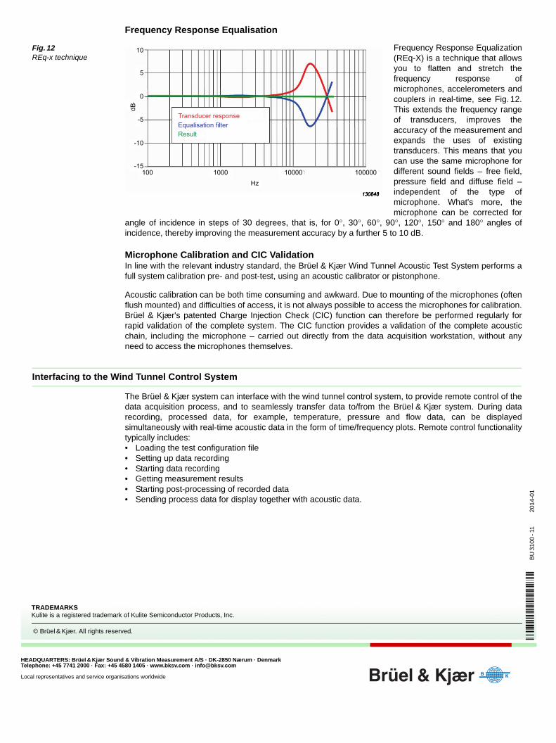
Frequency Response Equalisation
Fig. 12 REq-x technique
Frequency Response Equalization(REq-X) is a technique that allowsyou to flatten and stretch thefrequency response ofmicrophones, accelerometers andcouplers in real-time, see Fig. 12.This extends the frequency rangeof transducers, improves theaccuracy of the measurement andexpands the uses of existingtransducers. This means that youcan use the same microphone fordifferent sound fields – free field,pressure field and diffuse field –independent of the type ofmicrophone. What's more, themicrophone can be corrected for
angle of incidence in steps of 30 degrees, that is, for 0°, 30°, 60°, 90°, 120°, 150° and 180° angles ofincidence, thereby improving the measurement accuracy by a further 5 to 10 dB.
Microphone Calibration and CIC ValidationIn line with the relevant industry standard, the Brüel & Kjær Wind Tunnel Acoustic Test System performs afull system calibration pre- and post-test, using an acoustic calibrator or pistonphone.
Acoustic calibration can be both time consuming and awkward. Due to mounting of the microphones (oftenflush mounted) and difficulties of access, it is not always possible to access the microphones for calibration.Brüel & Kjær's patented Charge Injection Check (CIC) function can therefore be performed regularly forrapid validation of the complete system. The CIC function provides a validation of the complete acousticchain, including the microphone – carried out directly from the data acquisition workstation, without anyneed to access the microphones themselves.
Interfacing to the Wind Tunnel Control System
The Brüel & Kjær system can interface with the wind tunnel control system, to provide remote control of thedata acquisition process, and to seamlessly transfer data to/from the Brüel & Kjær system. During datarecording, processed data, for example, temperature, pressure and flow data, can be displayedsimultaneously with real-time acoustic data in the form of time/frequency plots. Remote control functionalitytypically includes:• Loading the test configuration file• Setting up data recording• Starting data recording• Getting measurement results• Starting post-processing of recorded data • Sending process data for display together with acoustic data.
10
5
0
-5
-10
-15100 1000 10000 100000
Hz
dB
Transducer responseEqualisation filterResult
TRADEMARKSKulite is a registered trademark of Kulite Semiconductor Products, Inc.
© Brüel & Kjær. All rights reserved.