Embed Size (px)
Citation preview

SYSTEM STUDY OF TWO DIMENSIONAL MAGNETIC
RECORDING SYSTEM
A DISSERTATION
SUBMITTED TO THE FACULTY OF THE GRADUATE
SCHOOL
OF THE UNIVERSITY OF MINNESOTA
BY
YAO WANG
IN PARTIAL FULFILLMENT OF THE REQUIREMENTS
FOR THE DEGREE OF
DOCTOR OF PHILOSOPHY
PROFESSOR RANDALL H. VICTORA, ADVIOSR
August 2014

© Yao Wang 2014

i
Acknowledgements
It is my fortune and pleasure to have a great professor - Randall Victora - to be my
advisor of PhD program in UMN. I appreciate his encouragement and patience in my
scientific pursuit. I enjoyed the great benefits of his unique insight and profound
knowledge of magnetic recording and micromagnetic theory during the research,
especially his prudent research attitude will guide me in the future work.
I would also like to acknowledge the great advice from Dr. Fatih Erden in Seagate
Technology during my work.
I am thankful to all my committee members Prof. Jian-ping Wang, Prof. Keshab Parhi
and Prof. William Cooper for their time, kindness and efforts of serving in my committee.
It has been a memorable experience with members of Professor Victora’s group and
other students in MINT center. I would like to thank Yan Dong for her knowledge and
experience I’ve inherited. I express the deepest appreciation to Sean Morgan for his
encouragement and support during my most difficult time. I would like to express my
special thanks to Chuan Zhang, Bo Yuan, Te-lung Kong for their help in my first year. I
also would like to thank all the colleagues including Yisong Zhang, Stephanie Hernandez,
Xiaohui Chao, Sumei Wang, Mazin Maqableh, Eliot Estrine, Xi Chen, Tao Qu, Xiaowei
Zhang, Todd Klein, Eunkyung Cho, Andrew Block, Anirudh Sharma , Madhukar
Reddy, Pin-wei Huang, Yipeng Jiao and many other friends for their friendship and help.
I am deeply grateful to my parents and sister. Without their love, support, tolerance
and advice, I would have never gone so far.

ii
Dedication
With gratitude to my parents.

iii
Abstract
In order to increase areal density above 1 Tbit/in2 for magnetic recording system, a two
dimensional magnetic recording (TDMR) system has been proposed as a possible
candidate to solve the trilemma of writability, signal-to-noise ratio and thermal stability.
Usually a shingled writer and two dimensional signal processing are implemented during
the writing and reading process for TDMR system, respectively. However, reaching the
user density as high as possible with a micromagnetic writer and reader, combined with
read channel is still a challenge for the study of TDMR. In this dissertation, a novel
reader design is proposed to readback above 1 Tbit/in2 density from granular media in a
TDMR system, which can even exceed 10 Tbits/in2
user areal densities when combined
with oversampling signal processing. Such a reader design is also extended to readback
of bit patterned media with 10 Tbits/in2 densities. A proposed shingled micromagnetic
writer combined with the new reader is able to reach user density above 4 Tbits/in2 and
near 6 Tbits/in2 for 8nm and 6nm Voronoi grains, respectively.
Readback at ultra-high density from a granular media with a realistic reader, such as
that envisioned for two-dimensional magnetic recording, is quite challenging due to the
increased inter-track interference, inter-symbol interference, increased writing errors and
an extremely low signal-to-noise ratio (SNR) environment. A novel reader design is
proposed to address the difficult problems for readback, which avoids the necessity for a
complex 2-D detector and head array, or latency issues if a single head was employed in
the normal orientation. The key idea is a rotated sense head, so that the shields are
aligned down-track, combined with oversampled signal processing to regain the lost
down-track resolution. Based on a random Voronoi grain model with perfect writing,

iv
simulation indicates that the new design can decrease the BER by a factor of five
compared to a normally positioned head array, and greatly increase user areal density
above 10 Tbits/in2 for a single-rotated singled head with sampling period of 2nm, a
minimum mean squared error equalizer, and pattern-dependent noise prediction detector.
If a quasi-cyclic low-density parity-check (QC-LDPC) code is implemented for error
correction, the performance of a normally oriented head array is about 8.5 dB worse than
the rotated head array (RHA).
The study indicates that the significant improvement in performance in the rotated head
compared to the normally oriented head can be attributed to the larger amplitude of its
dibit response and the reduced overlap between conditional probability density functions.
This new design is also examined for densities of 2-7 Tbits/in2 for TDMR system;
simulation shows that the new design achieves a density gain of 1.7X (single head) and
2.1X (head array) over a normally oriented single head at a target bit error rate (BER) of
10−3
with oversampling signal processing.
If the rotated reader is used to readback bit patterned media recording at 10 Tb/in2
density, it offers more than 20 dB gain compared with a normally oriented head array for
a target BER of 10-3
. The tradeoff between oversampling and increased target length is
examined. Island jitters are found to be non-Gaussian distributed. The performance of the
new design is also investigated for various bit patterns, island jitter and head noise.
Micromagnetic writing on 8nm grains and readback with various readers has also been
studied. For a conventional writer recording a pseudo-random binary sequence with 2
Tbits/in2 channel bit density, user densities of 1.52 Tbits/in
2 and 1.09 Tbits/in
2 can be
achieved with a rotated single sense head (RSH) and a normally oriented single head

v
(NSH) respectively, using oversampling signal processing. Simulation indicates that a
RSH with multiple scans and 2D equalization provides better resistance to a skew angle
of 15° than NSH. An optimized shingled writer is proposed; simulation indicates that a
RSH and RHA can reach a user areal density of 3.76 and 4.52 Tbits/in2 for 2 grains per
channel bit, which is close to the predicted maximum user areal density (4.66 Tbits/in2)
for this grain size obtained with an ideal writer and reader.

vi
Table of Contents
Acknowledgement…………………………………………………………………………i
Dedication………………………………………………………………………………....ii
Abstract …………………………………………………………………………………. iii
Table of Contents………………………………………………………………………... vi
List of Tables……………………………………………………………………………..xi
List of Figures……………………………………………………………………………xii
Chapter 1 Introduction………………………………………………………………..1
1.1 development of data storage technology…………………………………………...1
1.2 Basic magnetic component for perpendicular magnetic recording ………………..2
1.2.1 The basic component of hard disk drive……………………………….....2
1.2.2 Basics of magnetic recording……………………………………………...4
1.2.3 Magnetic write head……………………………………………………….5
1.2.4 Magnetic recording media………………………………………………...7
1.2.5 Magnetic read head ……………………………………………………….8
1.3 Challenges for magnetic recording above 1 Tb/in2………………………………11
1.4 Possible candidates for density above 1 Tbits/in2……………………………….13
1.4.1 Bit patterned magnetic recording………………………………………...14
1.4.2 Heat-assisted magnetic recording………………………………………..15
1.4.3 Two-dimensional magnetic recording…………………………………...16

vii
1.5 Overview of signal processing techniques………………………………………18
1.5.1 Modulation code ………………………………………………………...19
1.5.2 Partial response equalization……………………………………………..20
1.5.3 Detection…………………………………………………………………22
1.5.4 Error correction codes……………………………………………………24
1.5.5 Writing precompensation……………………………………….………..25
1.6 The scope of this thesis ………………………………………………………….26
Chapter 2 Micromagnetic Modeling……………………………………………………30
2.1 Landau-Lifshitz-Gilbert equation……………………………………………….30
2.2 Discretization of magnetic recording system……………………………………31
2.3 Energy term and associated field………………………………………………..32
2.3.1 Magnetostatic energy……………………………………………………33
2.3.2 Exchange coupling energy……………………………………………....35
2.3.3 Magnetocrystalline anisotropy energy…………………………………..37
2.3.4 Zeeman energy…………………………………………………………..38
2.3.5 Thermal fluctuation……………………………………………………...38
Chapter 3 Novel Reader Design for 10 Tbit/in2 User Areal Density in Two Dimensional
Magnetic System.…………………………………………………………...40
3.1 Introduction……………………………………………………………………….40
3.2 The design of the reader…………………………………………………………..41

viii
3.2.1 Previous read head array…………………………………………………..41
3.2.2 Rotated head array………………………………………………………...43
3.3 Detection schemes with the new head design……………………………………45
3.3.1 Detection system architecture……………………………………………..45
3.3.2 Detection with rotated single head………………………………………...46
3.4 Numerical evaluation……………………………………………………………...48
3.5 Study on response of various reader designs……………………………………...51
3.5.1 Linear response of various readers………………………………………...52
3.5.2 Read head sensitivity response…………………………………………….53
3.6 Signal processing and performances comparisons for various readers……………55
3.6.1 The channel capacities for various readers………………………………..55
3.6.2 Performances for various coded systems…………………………………58
3.7 Conclusion………………………………………………………………………….60
Chapter 4 System Design for Readback above 1 Terabit/Inch2 from Granular Media..62
4.1 Introduction…………………………………………………………………………62
4.2 Reader design……………………………………………………………………….63
4.2.1 Principle and structure of reader…………………………………………...63
4.2.2 Parameters for simulation………………………………………………….64
4.2.3 Detection with designed head……………………………………………...65
4.3 Numerical evaluation……………………………………………………………….66

ix
4.3.1 Optimum bit aspect ratio for various readers………………………………66
4.3.2 BER VS grains per channel bit…………………………………………….70
4.3.3 The effect of head noise on performance…………………………………..72
4.3.4 Effect of magnetic fly height on performance……………………………...72
4.3.5 Effect of shield-to-shield spacing on performance…………………………74
4.4 Conclusion………………………………………………………………………….75
Chapter 5 Reader Design for Bit Patterned Media Recording at 10 Tbits/in2 Densities...77
5.1 Introduction…………………………………………………………………………77
5.2 Reader design……………………………………………………………………….78
5.2.1 Normal read head array……………………………………………………78
5.2.2 Rotated head design…………………………………………………………80
5.3 Detection schemes with various head designs……………………………………...81
5.3.1 Writing and reading process………………………………………………...81
5.3.2 Detection with various head designs………………………………………..81
5.4 Numerical evaluation of the new design with white noise…………………………83
5.4.1 Further study on the read back in TDMR system…………………………..83
5.4.2 New head design in the BPMR system……………………………………..84
5.5 Numerical evaluation with more realistic parameters……………………………..88
5.5.1 Simulation methods………………………………………………………88
5.5.2 Study on islands jitter noises……………………………………………..90

x
5.6 Conclusions…………………………………………..………………………….93
Chapter 6 Study of Two-dimensional Magnetic Recording System including
Micromagnetic Writer………………………………………………………95
6.1 Introduction………………………………………………………………………..95
6.2 Shingled recording-conventional writer…………………………………………..96
6.2.1 Conventional writer design……………………………………………….96
6.2.2 ECC media design………………………………………………………...97
6.2.3 Reader design and detection scheme……………………………………..97
6.2.4 Simulation results for the conventional shingled writer………………….99
6.2.5 Effect of skew…………………………………………………………...100
6.3 Optimized writer design………………………………………………………….101
6.3.1 Specification of optimized writer………………………………………..101
6.3.2 Field profile………………………………………………………………103
6.3.3 Densities reached by the designed head………………………………….105
6.4 Conclusion……………………………………………………………………….107
Summary ……………………………………………………………………………….108
Reference……………………………………………………………………………….111

xi
List of Tables
Table 3.1 BER for detection with normally oriented single head and head array with
threshold and Viterbi detector …………………………………………………………...42
Table 3.2 Noises for various sampling periods………………………………………...45
Table 3.3 BER for both single head with Viterbi detector and PDNPD for 5.5nm
grain……………………………………………………………………………………...49
Table 3.4 BER for various head widths…………………………………………………50
Table 3.5 BER for both head arrays for 8nm grain………………………………………50
Table 3.6 BER for both head arrays for 5.5nm grain…………………………………….50
Table 4.1 Geometric parameters of read head for various channel bit densities………...64
Table 4.2 Relation between grains per channel bit and channel bit density……………..65
Table 4.3 Noises for various readers and sampling periods……………………………65
Table 5.1 BER for various target length and sampling periods in TDMR system……84
Table 5.2 Noises for various sampling periods………………………………………….90

xii
List of Figures
Figure 1.1 The areal density history in magnetic hard disk drive industry……………….2
Figure 1.2 Basic components of hard disk drive….……………………………………...3
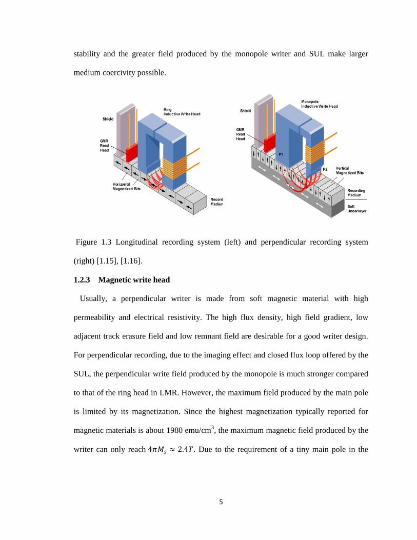
Figure 1.3 Longitudinal recording system (left) and perpendicular recording system (right)
……………………………………………………………………………………………..5
Figure 1.4 The air bearing surfacre (ABS) view of conventional writer (left) and shingled
writer (right)……………………………………………………………………………….7
Figure 1.5 Spin valve based on the GMR effect…………………………………………..9
Figure 1.6 The ABS view for optimizing CPP read-head structure……………………..11
Figure 1.7 The trilemma for increasing magnetic recording densities…………………..13
Figure 1.8 Schematic of BPMR system………………………………………………….14
Figure 1.9 A schematic diagram of an HAMR recording system……………………….16
Figure 1.10 Illustration of shingled-writing……………………………………………...17
Figure 1.11 System diagram of the perpendicular recording system…………………….19
Figure 2.1 Damped gyromagnetic precession of the magnetization moment ……….31
Figure 2.2 Discretization of a perpendicular magnetic recording system using a monopole
and Voronoi grains with soft underlayer ……………………………………………32
Figure 2.3 Magnetostatic interaction between two Voronoi grains……………………35
Figure 3.1 Schematic of an array of three conventional MR heads on continuous media
……………………………………………………………………………………………43
Figure 3.2 (a) Normal single head design; (b) Rotated single head design……………43
Figure 3.3 Schematic of the detection system architecture………………………………46
Figure 3.4 Normalized dibit responses along the down-track direction for the normally-

xiii
oriented head with and without ATI and rotated single head with ATI (Normally oriented
head with no ATI closely overlaps rotated head with ATI)……………………………...53
Figure 3.5 Read head sensitivity response for rotated head in the simulation…………...54
Figure 3.6 Block diagram for LDPC-coded TDMR system……………………………..56
Figure 3.7 BER for various reader designs………………………………………………57
Figure 3.8 Capacity (user bits/channel bits) for various systems………………………57
Figure 3.9 Conditional probability density function of equalized output for both rotated
and normally oriented head array………………………………………………………59
Figure 3.10 BER for various quasi-cyclic LDPC coded systems with code rate 0.8125 as
a function of head and system SNR……………………………………………………...60
Figure 3.11 BER for various quasi-cyclic LDPC coded systems with different code rates
as a function of head and system SNR…………………………………………………...60
Figure 4.1 (a) Normal single head design. (b) Rotated single head (RSH) design………64
Figure 4.2 BER vs. BAR for various heads and sampling periods at 2 Tbits/in2 channel
bit density………………………………………………………………………………...67
Figure 4.3 BER vs. BAR for various heads and sampling periods at 3 Tbits/in2 channel
bit density………………………………………………………………………………...67
Figure 4.4 BER vs. BAR for various heads and sampling periods at 4 Tbits/in2 channel
bit density………………………………………………………………………………...68
Figure 4.5 BER vs. BAR for various heads and sampling periods at 5 Tbits/in2 channel
bit density………………………………………………………………………………...68
Figure 4.6 BER vs. BAR for various heads and sampling period at 7 Tbits/in2 channel bit
density……………………………………………………………………………………69

xiv
Figure 4.7 Optimum bit aspect ratio for various heads………………………………….70
Figure 4.8 BER vs. grains per channel bits for various heads with sampling per bit……70
Figure 4.9 BER vs. grains per channel bits for various heads with sampling 2nm……71
Figure 4.10 BER vs. grains per channel bit for various head noise……………………..72
Figure 4.11 BER curve for various MFHs with both heads……………………………..73
Figure 4.12 Comparison of performance of three heads at 7nm MFH with RSH at MFH
in Table4.1……………………………………………………………………………….74
Figure 4.13 BER curve for various SSS with three heads……………………………….74
Figure 5.1 Schematic of head array on the bit patterned media...…….………………….79
Figure 5.2 (a) Normal single head design for BPMR; (b) Rotated single head design for
BPMR……………………………………………………………………………………80
Figure 5.3 BER curves for various head designs with sampling period of one bit………85
Figure 5.4 BER curves for various heads and sampling periods………………………...86
Figure 5.5 BER curve for new designs with various MFH………………………………87
Figure 5.6 (a) Rectangular array for 10 Tbits/in2; (b) Hexagonal array for 10 Tbits/in
2..87
Figure 5.7 BER curves for hexagonal array of bits with various sampling periods…….88
Figure 5.8 Histogram for normalized jitter induced voltage using the Taylor expansion
technique…………………………………………………………………………………91
Figure 5.9 Histogram for normalized jitter induced voltage using exact signal…………91
Figure 5.10 Histogram for normalized jitter induced voltage with 9nm head…………92
Figure 5.11 Histogram for normalized jitter induced voltage with 18nm head………….92
Figure 5.12 BER VS media jitter and head noises for various schemes………………...93
Figure 6.1 Down-track view of the conventional writer…………………………………96

xv
Figure 6.2 Schematic of rotated head array design………………………………………98
Figure 6.3 User areal density for various heads and media thicknesses ……………...100
Figure 6.4 The BER for various heads with both skewed and no skew cases for the
10nm medium…………………………………………………………………………..101
Figure 6.5 Optimized shingled recording head (a) the down-track view; (b) the air bearing
surface view. …………………………………………………………………………...104
Figure 6.6 Shingled head perpendicular field profiles resulting from micromagnetic
simulations……………………………………………………………………………...104
Figure 6.7 Perpendicular field gradients along both down and cross track directions...105
Figure 6.8 (a) Random magnetization pattern to be written on the granular medium. (b)
The final written pattern using the proposed optimized writer…………………………105
Figure 6.9 User areal density for the RSH and the RHA at 2.88 and 2 grains/channel bits
for the optimized writer………………………………………………………………...107

1
Chapter 1 Introduction
In this chapter, the background information combined with the motivation and
outline of the thesis is presented. A brief history of data storage technology is first
introduced. The magnetic components for recording are reviewed. Then the challenges
and physically fundamental limits are discussed, and possible candidates for density
above 1Tbits/in2 are explained with their own advantages and disadvantages.
Additionally the signal processing technique for the read channel is briefly described.
Finally, the scope of the thesis is presented.
1.1 Development of data storage technology
The hard disk drive has undergone both evolutionary and revolutionary changes at a
tremendous pace since its invention. Fig.1.1 indicates how the areal density of magnetic
recording increased since the first commercial product [1.1]. The first commercial hard
disk drive was introduced by IBM in 1956, which was called the random access method
of accounting and control (RAMAC). It can store about 5MB data with the areal density
of 2Kb/in2 and provide a data transfer rate of 8.8 KB/s [1.2]. By the end of 1990s, the
longitudinal magnetic recording (LMR) has been the dominant technology for hard disk
drive, where the magnetization lies in the plane of a thin film media [1.3]. However, the
difficulty of striking a balance among thermal stability, signal-to-noise ratio and
writability make LMR slow down and remain below 130 Gbits/in2 [1.4]. Around 2005,
perpendicular magnetic recording (PMR), where the magnetic anisotropy aligns
perpendicular to the media planes, has taken the place of LMR in HDD product as it can
achieve the areal density of above 500 Gbits/in2 [1.5] [1.6] [1.7]. It is believed the
limitation of the achievable areal density by PMR is around 1 Tbits/in2 [1.8]. In order to

2
further increase the density above 1 Tbits/in2, some novel magnetic recording
architectures have been proposed, such as heat-assisted magnetic recording (HAMR)
[1.9], [1.10], bit patterned magnetic recording (BPMR) [1.5] and two dimensional
magnetic recording (TDMR) [1.7], [1.11] . In 2013, Seagate demonstrated the milestone
storage density of 1 Terabits per square inch with HAMR [1.12]. It is further believed
that achieving toward or above 10 Tbits/in2 is possible by using the HMAR technology to
write on the bit patterned media [1.13].
Figure 1.1 The areal density history in magnetic hard disk drive industry [1.1].
1.2 Basic magnetic component for perpendicular magnetic recording
1.2.1 Basic components of hard disk drive
The basic components of hard disk drive are shown as Fig.1.2 [1.14]. For a typical
hard disk drive (HDD) design, those flat circular disk named platters are utilized to keep
the recorded data, which are held by a spindle. The platters are made from a nonmagnetic
material, coated with a thin layer of magnetic material of thickness 10~20nm, then coated

3
with a carbon layer as protection. The information is written and read by the write/read
head, which is located at the tailing edge of slider. Usually there are multiple platters for
each HDD, and one write/read head for each platter. The rotation of the platter is
controlled by a spindle motor, while during the writing and reading process, the
read/write head assembly is moved radially across the spinning platters with an actuator
arm controlled by a voice coil actuator. The fly height between the slider and the spinning
disk is controlled with a self-pressurized air bearing mechanism. When the head
assembly and slider are positioned along the radical direction, different data tracks are
written on the disk.
Figure1.2 Basic components of hard disk drive [1.14].
A hard disk drive usually consists of four major parts: a head-disk assembly (i.e.
magnetic read/write heads and magnetic disk), data detection electronics and write circuit,
mechanical servo and control system and interface to microprocessor. Here we will focus
on the head-disk assembly, the data detection scheme and writing current control due to
their closeness to the research.

4
1.2.2 Basics of magnetic recording
A nonvolatile information storage device is constructed from a physical system
accommodating two distinctive states. Such two states can be altered back and forth by a
transducer, and produce distinguishable signal detected by the other transducer. For
magnetic recording, the two distinctive states are formed by magnetic hysteresis, and
altered by the different magnetic field produced by the magnetic writer and sensed by the
magnetic reader. There are two important magnetic recording systems during the
development of magnetic recording technology, i.e. the longitudinal and perpendicular
magnetic recording system, illustrated by Fig.1.3 [1.15], [1.16]. For longitudinal
magnetic recording, the anisotropy of the medium grains is longitudinal, which aligns the
magnetization within the plane of thin recording layer. The bits are written with the stray
field in the medium near the head gap, which is produced with the ring head driven by a
writing current [1.17]. For perpendicular magnetic recording, the anisotropy of the
medium grains is perpendicular to the plane of recording layer. The bits are written with a
monopole writer, whose field can be ideally doubled due to the magnetic image offered
by the soft underlayer under the recording layer. Currently the LMR has been replaced by
PMR due to the great advantage offered by PMR with respect to achievable density. In
longitudinal recording, the space charged domain walls formed between the bits produce
large magnetostatic fields, which destabilize the recorded magnetization and broaden the
transition. Correspondingly, severe transition jitter and nonlinear transition shift are
produced. On the contrary, the magnetostatic fields produced by the grains in PMR
stabilize the magnetization and favors sharp transitions due to the perpendicular
anisotropy of the medium grains. Also the thicker media guarantees more thermal
5
stability and the greater field produced by the monopole writer and SUL make larger
medium coercivity possible.
Figure 1.3 Longitudinal recording system (left) and perpendicular recording system
(right) [1.15], [1.16].
1.2.3 Magnetic write head
Usually, a perpendicular writer is made from soft magnetic material with high
permeability and electrical resistivity. The high flux density, high field gradient, low
adjacent track erasure field and low remnant field are desirable for a good writer design.
For perpendicular recording, due to the imaging effect and closed flux loop offered by the
SUL, the perpendicular write field produced by the monopole is much stronger compared
to that of the ring head in LMR. However, the maximum field produced by the main pole
is limited by its magnetization. Since the highest magnetization typically reported for
magnetic materials is about 1980 emu/cm3, the maximum magnetic field produced by the
writer can only reach . Due to the requirement of a tiny main pole in the

6
writing process of magnetic storage owing to the required gradient and avoid any of
adjacent neighbor erasure, the actual recording field is much smaller than 2.4T [1.18].
In order to decrease the erasure of adjacent bits caused by the writing with the mono
pole, a trailing shield is placed in the proximity of the trailing edge to increase the field
gradient without decreasing the field substantially. Correspondingly, a sharper transition
is written at the trailing edge of the writer when the head moves, and an improved bit
error rate performance can be achieved. As the density keeps increasing, the track width
is compressed to increase the total areal density. Under such a condition, it is important to
obtain a low adjacent track erasure field while keeping the high field gradient along the
down-track direction. Correspondingly a smaller main pole and wrap around shield
(WAS) is needed to guarantee high field gradients on both down-track and cross-track
directions and keeps the lower adjacent track erasure field, shown in Fig.1.4 [1.19]. When
the areal density increases higher, the main pole size is needed to be further decreased in
order to decrease the erasure of adjacent bits and tracks; however, too small main pole
cannot produce strong enough field to write the high coercivity grains. This dilemma can
be solved with a new writing scheme called shingled writing [1.6], [1.11]. The shingled
writer uses its corner to write a wide track, and then trims the previous track width into a
narrower track utilizing the track overlap when it moves across one track away, shown in
Fig.1.4. Correspondingly, a wider writer can be used to write a narrower track. Besides
only the field gradients along the two sides of the writer corner are concerned, the
constraints on the design of the writer are loosened compared to the writer design for
conventional magnetic recording. If the user density near 10 Tbits/in2 is desired, a laser
and a waveguide combined with near field transducer are positioned near the

7
conventional perpendicular writer to write the bits on the medium above Curie
temperature, and store it when it cools down; such a technology is called HAMR [1.9],
[1.10].
Figure 1.4 The air bearing surfacre (ABS) view of conventional writer (left) and shingled
writer (right) [1.19].
1.2.4 Magnetic recording media
In order to reach the stable and satisfying writing performance for perpendicular
recording, the recording media needs satisfy several requirements such as high coercivity,
perfect squareness, uniform grain size and well isolated granular structure. At the
beginning of magnetic recording, particulate media was fabricated. With the development
of vacuum technology, thin film media can be fabricated, which can offer a smooth
surface and higher packing density compared to particulate media. With the increase of
recording density, smaller grains with higher anisotropy are needed to keep the thermal
stability of the grains and enough SNR; however the field produced by the writer is
limited by the magnetization of the material. Correspondingly, some new media designs
are needed to solve this dilemma. Victora and Shen [1.20] proposed an exchanged
coupled composite media for perpendicular magnetic recording, which consists of

8
magnetically hard and soft region. The high anisotropy of the hard region keeps the
thermal stability of the grain, while the easier switching of the magnetization in the soft
region facilitates the rotation of the magnetization in the hard region, decreasing the
switching field. Another multilayer exchange spring media was designed by Suess [1.21]
for magnetic recording, where domain walls nucleated in the bottom softest region is
propagated along the column of grains. Such a media can decrease coercivity more than a
factor of two while keeping the same energy barrier as a single phase media.
1.2.5 Magnetic read head
Prior to 1990, a inductive head was used as a magnetic read head for all hard disk
drives, whose readback signal magnitude is proportional to the magnetic flux from the
recorded bit, the number of turns of coils wrapped around the head and the relatively
velocity between the head and disk. However, the magnetic flux produced by a smaller
bit decreased when the recording density increases and the number of turns of coils and
the disk velocity (limited by engineering techniques) make the readback signal from an
inductive head too small to provide adequate signal-to-noise ratio, which require the
invention of more powerful detectors. However, magnetoresistive (MR) heads were the
successful answer, which become a landmark in magnetic recording history and boost the
achievable density greatly. Compared to the inductive head, the magnetoresistive heads
read back based on a totally different principle. The resistance of the head changes when
the magnetic flux from the disk changes, which is independent of the disk velocity.
Correspondingly, the readback signal is the same for any speed. Besides, the resultant
signal from the magnetoresistive head is directly proportional to the MR ratio, which

9
produces a larger signal than that of inductive head. Hence the SNR of readback signal is
improved greatly.
In 1988, the first observation of giant magnetoresistance (GMR) by Grünberg and Fert
were made on Fe/Cr/Fe trilayers and multilayers [1.22], [1.23]. Such a structure exhibits
a low and high resistance state when the ferromagnetic layers are parallel or antiparallel
to each other, respectively. The principle for GMR can be briefly explained with a two
channel model, shown in Fig.1.5 [1.24]. It is known that the travelling electrons interact
with the ferromagnetic superlattice differently when their spin directions are opposite to
the magnetization of the lattice compared with the parallel case. Hence one spin direction
scatters less as it passes through both layers in the parallel case, while both spin
directions scatter equally at the antiparallel case.
Figure 1.5 Spin valve based on the GMR effect [1.25].
When the MR device is used as a magnetic read head, the magnetostatic field produced
by the recorded patterned on the media causes the switching of local magnetic moment in
the free layer, correspondingly the magnetoresistance of the head varies depending on the

10
relative direction of the magnetizations in the multiple layers. In order to enhance the
SNR of the readback signal for MR head, usually the sensing structures are positioned
between two soft magnetic layers named shields to prevent the sense of magnetic flux
from adjacent bits. Additionally a longitudinal bias scheme is utilized with two
permanent magnets abutting the MR element along the longitudinal direction in order to
maintain the single-domain state of the element, but without sacrificing its sensitivity.
There are two types of GMR head depending on the relative direction of current and
the layer plane, which are current-in-plane (CIP) GMR and current perpendicular to plane
(CPP) GMR heads [1.25], [1.26]. The CIP GMR head is first adopted as the read head in
hard disk drive in early 1990s, it shows great performance improvement compared to the
anisotropic magnetoresistive (AMR) head and inductive head. However it seems to be
reaching its limit due to the decrease of head efficiency with the decreasing read gap
length or read track width and a rising temperature caused by a large sense current
density. And thus for the recording density over 100-200 Gbpsi, the CPP GMR seems to
be the next generation of read head due to its larger intrinsic MR ratio, lower heating
issue by the current and increased ( the resistance change and element area product),
illustrated as Fig.1.6 [1.26]. If the recording density further increases, the ∆RA of CPP-
GMR needs to be further increased with some new material and structure, such as
choosing material with large spin asymmetry coefficients [1.27], utilizing a half-metallic
magnet [1.28] or some confined-current-path structures [1.29]. Another magnetic tunnel
junction (MTJ) device is widely used as the read head, which shows much larger MR
ratio than that of GMR device. For example, CoFeB/MgO/CoFeB MTJs shows the giant
TMR effect, and the MR ratios can reach 200-500% at room temperature (RT). However,

11
the low RA products and much higher MR ratios are needed for high recording density.
For example, a RA product below 1Ω um2 and a MR ratio of above 50% are required for
areal recording densities above 500 Gbit/inch2 [1.30]. Hence a low RA product and a
high MR ratio with MTJs are needed for high recording density.
Figure.1.6 The ABS view for optimizing CPP read-head structure [1.27].
1.3 Challenges for magnetic recording above 1Tb/in2
In order to increase the storage density, the bit size needs to be decreased during the
recording process. However, the signal-to-noise ratio (SNR) is proportional to the
number of magnetic grains per bit (N), namely SNR (dB) ~ log (N) [1.31]. It is necessary
to scale the size of magnetic grains when scaling the bit size so as to keep good enough
SNR. By scaling all the relevant physical dimensions (such as bit size, grain size, writer
and reader geometry, magnetic fly height, media thickness), the magnetic hard disk drive
industry successfully increased the recording density by around 30% per annum for
perpendicular magnetic recording technologies over the past ten years. However, thermal
stability will prevent the continuing scaling of the magnetic grains for ultra-high density

12
recording, in other words, grain size smaller than the physical limit is likely to allow the
magnetization to switch within a shorter time than the required time-scale (e.g. 10 years)
for magnetic recording technology due to thermal fluctuation [1.32].
Superparamagnetism is a form of magnetism, in which small ferromagnetic or
ferromagnetic nanoparticles may exhibit a behavior (such as the random flip of the
magnetization under the influence of temperature) even at temperature below the Curie
temperature. For the change of magnetization, usually irreversible switching needs to
overcome an energy barrier in some part of the particle configuration, and thermal
energy can greatly aid the crossing of the energy barrier. Assuming a uniaxial and single
domain particle and the magnetic field applied along the easy axis, then the energy
barrier needed to overcome to switch from one direction to the other direction is
, where Ku is the anisotropy constant of the material, V is the volume of the
particle and
⁄ . If KuV is too small when the grain size shrinks, then thermal
energy can overcome the anisotropy energy to randomly switch the magnetization from
one easy axis direction to the other even without the applied field. Usually the anisotropy
energy KuV for the granular grain in data storage is within the range of 40kBT and 70kBT
to make it thermal stable around 10 years, where kB is the Boltzmann constant.
Correspondingly, the superparamagnetic limit imposes a well-known trilemma of SNR,
thermal stability and writability for magnetic recording, shown as Fig.1.7. First, as
mentioned before, when the number of grains per bit is decreased, the SNR becomes
inferior. Additionally, the transition noise take the dominant role since the reduction of
bit size reduces the area of low noise region. Correspondingly the grain size needed to be

13
decreased to keep enough grains per bit for enough SNR. It seems increasing Ku is
inevitable for the thermal stability, which also means higher magnetic field produced by
the writer is necessary to switch the magnetization of the grain. However, the maximum
field produced by the main pole is decided by its magnetization. Since the highest
magnetization for all reported magnetic materials is about 1980 emu/cm3, the maximum
magnetic field produced by the write can only reach . Due to the
requirement of a tiny main pole in the writing process of magnetic storage considering
the gradient and avoid of adjacent neighbor erasure, the actual recording field is much
smaller than 2.4T [1.18].
Figure 1.7 The trilemma for increasing magnetic recording densities.
1.4 Possible candidates for density above 1 Tbits/in2
It seems the trilemma for magnetic recording has produced a dead end; fortunately,
several new recording architectures are being explored to increase the areal density
beyond these limits. Such new options include bit patterned magnetic recording (BPMR)
[1.5],[1.33], heat assisted magnetic recording (HAMR)[1.9],[1.10] and shingled write

14
recording (SWR) [1.11] combined with 2-D readback and signal processing, namely two-
dimensional magnetic recording (TDMR) [1.7].
1.4.1 Bit-patterned magnetic recording
For conventional granular media, the irregularity of grains and the strong magnetic
interaction among grains cause severe modulation noise and transition noise, and the
SNR is degraded at ultra-high areal density. For BPMR [1.5], [1.33], the information is
stored at a uniform, well-defined and separated magnetic island with lithographical
technology, which reduces the transition noise and non-linear bit shift. It also provides a
solution for superparamagnetic problems as the thermal stability is decided by the
anisotropy and whole volume of a single island instead of a single grain, shown in Fig.1.8.
With micromagnetic simulation, the recording performance of BPMR for areal density of
4Tbit/in2 is studied [1.33].
Figure1.8 Schematic of BPMR system [1.13].
Traditional lithography techniques seem inadequate to fabricate BPM with feature size
less than 20nm, although electron beam lithography, limited by its low throughput, can be
applied for such a small feature [1.13]. Also, lithography jitter can cause variations in
islands size and position. In addition, the variation in writing synchronization and
fluctuation in switching field leads to writing error. When the areal density is increased,
inter-symbol interference (ISI) and inter-track interference (ITI) will be prominent due to

15
the close arrangements of islands on both down and cross track directions.
Correspondingly, this thesis involves the readback and explores the optimum
performance of such an environment with severe ITI, ISI, and island jitters for the BPMR
system.
1.4.2 Heat –assisted magnetic recording
HAMR is proposed to address the writing issue for granular media with extremely high
anisotropy, such as FePt whose switching field is around 50 kOe [1.10]. In heat-assisted
recording, the temperature of a high-anisotropy medium is locally elevated above the
Curie temperature to facilitate the writing process by significantly reducing the
magnetization switching field, and then quickly dropped below Curie temperature to store
recorded information [1.9]. The heating and cooling process is implemented on the same
time scale of about 1ns to achieve the necessary data rate and large thermal gradient for a
sharp transition. An example of an HAMR system is shown in Fig.1.9 [1.10]. A free-
space laser beam is coupled into a waveguide on the trailing edge of the slider using a
grating coupler. The previous technology of slider’s fabrication, air bearing and
magnetoresistive reader used in current perpendicular magnetic recording are still
implemented here. In order to form a diffraction limited focal spot, the waveguide is
shaped to form a planar solid immersion mirror (PSIM) [1.34]. A near field transducer
(such as a beaked metallic plate antenna) would further concentrate the focused optical
spot. With such high temperatures required for HAMR, the lubricant and the carbon
overcoat for the medium should be carefully designed to avoid poor tribological
performance caused by the high temperature.

16
Figure 1.9 A schematic diagram of an HAMR recording system [1.10].
There are three challenges for HAMR technology as follows: (1) Development of small
grain recording medium with good thermal and magnetic properties; (2) Development of
integrated optical and magnetic write head; (3) avoid any of the failure mechanisms
caused by the elevated temperatures in the head, medium, and at the head-disk interface.
1.4.3 Two-dimensional magnetic recording
TDMR combines two important techniques: shingled write recording (SWR) and 2-D
read back and signal processing. Shingled writer uses a much wider writer to write data
by heavily overlapping tracks; correspondingly the resulting tracks are much narrower
than the original written width, shown as Fig.1.10 [1.7]. For a shingled writer, since the
corner of the head is used to write the magnetization patterns, the design of such a head is
thus much relaxed compared to a conventional head. As the track pitch is independent of
head magnetic write width, the singled writer can provide much stronger write field

17
brought by the larger main pole. Also the sharp corner-edge field brings narrower erase
band, which enables us to increase track density.
Figure 1.10 Illustration of shingled-writing [1.7].
For readback, previous researchers usually assumed that 2-D signal processing which
utilizes the adjacent tracks’ information is needed for TDMR due to the similar high level
of inter-symbol interference (ISI) and inter-track interference (ITI). The information
about the current or adjacent track might be obtained with a head array or several passes
of a single head. Prototypes of conventional 1-D channels are now being built with
iterative detectors; similar techniques should be developed for 2-D detection, although
there is no practical 2D version of a Viterbi detector or its soft-detection derivatives.
Reference [1.35] has utilized 2-D maximum a posteriori (MAP) detectors in a TDMR
system and compared the performances of various detectors such as inversion, 1-D and 2-
D MAP detectors in a TDMR system. Reference [1.36] placed a special emphasis on the
suitability of the Voronoi model for the purpose of designing detectors for a TDMR
system, and proposed several detection schemes, such as three-track Viterbi algorithm

18
and the decision feedback Viterbi algorithm. Reference [1.37] used a linear minimum
mean-squared error (MMSE) equalizer and a low-density parity-check code to study the
detection in TDMR system. In this thesis, considering the asymmetric sensitivity head
response causing the asymmetric level of ITI and ISI, we proposed a rotated reader
design for sensing very high density magnetic recording data, such as that envisioned for
two-dimensional magnetic recording. The simulation indicates that the user density can
reach above 10 Tbits/in2 with the new design, which also avoids a much more complex 2-
D detector.
1.5 Overview of signal processing techniques
From the perspective of signal processing and coding techniques, the data storage
system can be treated as a communication system. A block diagram of the magnetic
recording system is shown as Fig.1.11. Before the writing process, the information is
encoded. The actual bits of information which have to be stored on the magnetic medium
are referred as “user bits”. The stream of user bits is encoded with an error correction
code (ECC) and then a modulation code prior to recording them in the form of changing
magnetization pattern. The purpose of the ECC encoder is to introduce extra bits to the
input stream to detect and correct some of the errors in the detected data. The modulation
encoder is necessary due to different system requirements such as the channel
synchronization, data detection and recording density consideration. Then the writing
precompensation is used by adjusting the writing current to reduce the effect of nonlinear
transition shift. In the read channel, usually a finite impulse response (FIR) equalizer is
used to shape the channel response to a desired and shorter partial-response target to
allow the practical implementation of maximum-likelihood sequence detection (MLSD).

19
Here sampling rate of the sampler before the equalizer can vary. If the signal is
oversampled before the equalization, then it’s called a fractional spaced equalizer. If a
softer decision decoding is performed, the soft-output Viterbi algorithm (SOVA) detector
or the Bahl-Cocke-Jelinek-Raviv (BCJR) detector will take the place of Viterbi detector
(VD). The partial-response target combined with the maximum likelihood detector is
known as the partial-response maximum likelihood (PRML) receiver. In the receiver end,
the modulation code and the error correcting code are decoded to recover the user data.
For the next paragraphs, we will introduce some basic signal processing and coding
techniques used in magnetic recording systems.
Figure 1.11 System diagram of the perpendicular recording system.
1.5.1 Modulation code
The purpose of a modulation code (constrained code) is for the channel synchronization,
data detection and recording density consideration. On one hand, the code has to ensure
the magnetization changes at least once within a certain number of channel bits, as long

20
segments of uniformly magnetized pattern will cause serious problems in channel
synchronization and detection [1.38], [1.39]. For synchronization, the phase-locked loops
circuit adjusts the phase of oscillator by comparing the signal from the current transition
with the prior values of the PLL clock. Correspondingly a long stream of zeros makes the
generation of phase update signals impossible and result in phase shifts. On the other
hand, the modulation code can constrain the minimum distance between adjacent
transitions during the recording process to avoid inter-symbol interference (ISI) and
nonlinear distortion.
For a peak detection system, run length-limited (RLL) code (namely (d, k) code) is
used as a modulation code to enhance the performance. Such a code constrain the
symbols “1” to be separated by at least d and at most k symbols “0” during an encoded
sequence. Analogous to the (d, k) code, a class of constrained codes denoted as (0, G/I)
code is implemented in the PRML channel to aid the recovery and simplify the design of
the Viterbi detector for the channel [1.40]. G means a global constraint which limits the
maximum run length of “0” symbols in any code string. I means an interleaved constraint,
which limits the maximum lengths of 0 symbols in each of the interleaves of a coded
sequence. For the need of a high channel capacity, a constrained code with a very high
code rates is used in real systems.
1.5.2 Partial response equalization
When the recording densities are low, intersymbol interference can be ignored due to
the adjacent transition being written sufficiently far away to result in a relatively isolated
voltage peak; thus peak detection technologies are utilized. When the recording density is
further increased, the intersymbol interference shifts peaks of readback signal and

21
decreases the signal amplitude, which causes poor performances for a peak detector.
Correspondingly, a new channel called a partial-response maximum likelihood (PRML)
channel was proposed to overcome the channel ISI [1.41], [1.42]. The basic idea for
partial response is to introduce several controlled amount of ISI into the recording data
pattern instead of trying to eliminate it. It usually assumes that the superposition of
readback signal from the adjacent track is linear and the shape of readback signal from an
isolated transition is exactly known. In order to decrease the state in the ML detector,
usually a finite impulse response (FIR) filter is utilized to shape the channel response to
some desired, shorter partial-response target. A classic type of partial-response channel,
class IV partial response (PR4) channel is widely used since the PR channel is proposed.
And the PR4 channel and its extended family of channels can be expressed with the
following polynomials,
y(D)=(1-D)(1+D)N (1.1)
where N≥1. For N=1,2 and 3, the channels that use y(D) as the channel transfer function
are called PR4, EPR4 and E2PR4 channels, respectively. The higher N is, the longer bit
periods that a target pulse extends over.
Later, the general partial response (GPR) target was proposed, which uses arbitrary
real numbers instead of integer value in the PR target. The equalizer using GPR target
reduces the noise enhancement and meanwhile whitens the noise compared to integer-
value PR equalizer [1.43], [1.44]. Reference [1.43] indicates the monic constraint on the
equalizer target response tends to whiten the noise samples at the equalizer output
compared to the fixed-energy constraint. Also the noise-predictive maximum likelihood
(NPML) detector is proposed based on the GPR target [1.45].

22
When the recording density keeps increasing, the track width is compressed to increase
the recording areal density; correspondingly the inter-track interference becomes more
and more severe and even comparable to ISI. Lots of novel equalization schemes have
been proposed to address the ITI issue in higher recording density. The performance of a
read channel in the presence of both ITI and additive white Gaussian noise (AWGN)
were analyzed with maximum-likelihood (ML) sequence detection [1.46], however such
an ML detector is quite complex when there is ITI. Then the suboptimal joint-track
equalization was first proposed in [1.46] and subsequently optimized and utilized in
perpendicular recording and BPMR [1.47], [1.48]. The core idea for joint-track
equalization is a one-dimensional equalizer with a 2D GPR target to match the channel
response of the main track with ITI. For detection, a Viterbi algorithm with a modified
trellis is utilized, where the modified trellis was obtained by adding branches considering
the ITI from immediately adjacent tracks. Further, a two-dimensional (2-D) equalizer
with a 2-D GPR target based on the minimum mean square error (MMSE) is proposed for
the read channel with ITI [1.49], which forces the ITI to be zeros and keeps only the
controlled ISI to avoid the complex 2-D Viterbi detector. Under severe ITI and ISI, the
use of iterative decision feedback detection (IDFD) [1.50] can provide superior
performances compared to the conventional 1-D equalization. Furthermore, multi-track
detection is proposed in [1.51] combined with joint-track equalizer and 2D equalizer ,
where the core idea is that a posteriori probabilities (APPs) obtained from the detection of
two adjacent-tracks is used as a priori information for the detection on the center track.
1.5.3 Detection

23
Before the invention of the PRML channel, peak detection was utilized in the
longitudinal magnetic recording. For perpendicular magnetic recording, combined with a
partial response target, the Viterbi or other trellis based detector is used to detect the data
sequence, which avoids the computational unfeasibility for pure maximum likelihood
sequence estimation.
The conventional Viterbi detector is an optimum sequence detector for a read channel
with ISI and AWGN. Its basic principle is to maximize the conditional
probability , where and are the received and input sequence, respectively. The
Viterbi detector is a trellis based detector, where the number of states are decided by the
modulation method and finite memory determined by the PR target length for PRML
channel. It selects the sequence that minimizes the accumulated branch metric as a
surviving sequence and discards the other merged sequences to the same state.
When soft decision decoding is needed, the soft-output Viterbi algorithm (SOVA) or
the Bahl-Cocke-Jelinek-Raviv (BCJR) detector will be used instead of the VD with hard
decision. SOVA considers a prior probability of the input symbol, and produces a soft
output measuring the reliability of the hard bit decision of the Viterbi algorithm by
considering the difference between the chosen branch metrics and the discarded branch
[1.52]. The BCJR algorithm is based on a trellis running two Viterbi-like algorithms. It
recursively calculate the forward state metrics and the backward state metrics, which are
associated with the branch metrics to estimate the a posteriori probability of each bit.
As the media noise in perpendicular magnetic recording channel is nonstationary,
correlated and data-dependent, the conventional Viterbi detector is no longer the optimal
detector since the noise is not AWGN. Correspondingly, modifications to the
24
conventional Viterbi detector are needed. A pattern-dependent noise predictive Viterbi
detector[1.53],[1.54],[1.55], which embedded a branch-dependent prediction of the noises
for each branch metric to better characterize the data-dependent nature of the transition
noises, shows a superior performance over the convention Viterbi detector. Pattern-
dependent noise predictive detector (PDNPD) is a near maximum likelihood sequence
estimation scheme for zero-mean, data-dependent, finite-memory Gauss-Markov noise.
Reference [1.56] proposed a mean-adjusted pattern-dependent noise prediction for the
channel consisting of both jitter noise and NLTS.
When the recording density keeps increasing, the track width is compressed and ITI
becomes a major detriment to detection, especially in TDMR systems. Correspondingly,
some multi-track detector, even 2-D detectors are proposed and utilized in ultra-high
recording density. Reference [1.57] views the off-track interference as the response of the
channel to an independent data sequence, simultaneously estimates the two data
sequences by joint PRML detection, and then simply discards the adjacent track data at
the end. Different from usually 1D detectors which suppress ITI with equalization, a 2-D
maximum a posteriori probability (MAP) detector [1.58], which treats ITI as useful
information to help the decision, is utilized in TDMR system, and it’s proved to obtain a
great density gain compared to 1-D MAP detector. However it is still prohibitively
complex even for modest sector sizes. The separable 2-D MAP detector [1.59] treats 2-D
ISI matrix as a product of a column and a row vector, and then a 2-D channel can be
treated to be a concatenation of two 1-D channels. Hence a relatively low-complexity
detector can be developed.
1.5.4 Error correction codes

25
The noises, nonlinear distortions and interference may cause errors for detection in
magnetic recording systems. Losing the information in a hard disk drive should be kept
as an extremely low-probability event, and the ultimate probability of error should be
around 10-14
. Correspondingly, error correction codes (ECC) is used after the detection to
correct errors during the writing and reading process, and it greatly boosted the reliability
of data recovery.
Usually, there are two types of error-correcting codes: codes of block type and codes of
convolutional type. Among the block typed code, a Reed-Solomon (RS) code and the
low-density parity-check (LDPC) codes are the two most important ECCs in magnetic
recording. RS codes are maximum distance separable (MDS) codes among the (n, k)
cyclic codes, namely it can achieve the maximum minimum Hamming distance: dmin=n-
k+1, and it can correct any burst of errors with a length of (n-k)/2. Meanwhile the hard
decoding of RS codes makes it easy to be implemented. The LDPC code could replace
the RS code in the future magnetic recording systems due to its near-capacity
performance. Additionally the adaptation of a parallelizable decoder, lower error-rate
floor and the superior performance in burst errors makes LDPC codes superior to turbo
codes.
1.5.5 Writing precompensation
Nonlinear transition shift (NLTS) is a phenomenon in which the transition location is
shifted due to the magnetostatic field produced by previous written transitions. The
complex nature of the nonlinear effects for NLTS means that very few theoretical studies
on the optimal precompensation of NLTS have been carried out. Usually the amount of
precompensation needed for NLTS is measured using several different approaches.

26
Pseudorandom sequences are used to measure the NLTS, which involves the recording of
a binary pseudorandom sequence and the capture and processing of the playback
waveform [1.60]. Harmonic elimination technique is also used to measure the nonlinear
bit shift, which is useful for designing, tuning and testing PRML precompensation
schemes [1.61]. In order to precompensate NLTS, besides the classic dibit
precompensation, other theoretical studies are carried out to obtain the optimal amount of
precompensation. Lim and Kavčić [1.62] showed how to compute these optimal
precompensations for partial erasure and nonlinear transition shift in a longitudinal
channel with dynamic programming, whose objective was to minimize the mean-squared
error between the output signal of a noisy, nonlinear channel and that of a linear channel
without noise. Wu [1.63] proposed a multilevel precompensation scheme which
precompensates different amounts for different dominant NLTS cases beyond the dibit
transition in order to minimize the BER of the read channel.
1.6 The scope of this thesis
As mentioned previously, TDMR is a promising candidate to reach density above 1
Tbits/in2. Usually a shingled writer is used to write data, and two dimensional signal
processing and powerful error correcting codes is used for recovering the readback signal
and reaching ultra-high storage density. However, on one hand, most signal processing
researchers utilized some simplified and unrealistic models (such as perfect writing, 2-D
symmetric Gaussian reader, extremely sharp resolution) and too complex advanced signal
processing techniques (such as 2-D detector) to study the detection in TDMR systems,
which makes the results far from the realistic system and such signal processing
algorithms are not likely to be utilized in the hard disk drive due to the high complexity

27
and latency. On the other hand, the researchers, who use micromagnetic simulation to
design the shingled writer and reader, most focus on the magnetic specification of the
head and media without really optimizing and analyzing the performance as a whole
system combined with a read channel, which makes such a design less accurate for a
complex recording system such as TDMR.
In this thesis, we combined both micromagnetic simulation and signal processing to
study the specifications and performance of TDMR system. First, a novel system design
for sensing very high magnetic recording data, such as that envisioned for TDMR, is
proposed. The key idea is a rotated sense head, so that the shields are aligned down-track,
combined with oversampled signal processing to regain the lost down-track resolution.
Based on a random Voronoi grain model, the bit error rate reached by both a rotated
sense head and normally positioned head array are compared with sampling period of 2
nm, a minimum mean squared error equalizer, and pattern-dependent noise prediction
detector. The user density reached by the new design is greatly increased above 10
Tbits/in2. The performances of both heads are further studied by using the quasi-cyclic
low-density parity-check (QC-LDPC) code in a TDMR system. The significant
improvement in performance of the rotated head compared to the normally oriented head
is studied and explained from a signal processing perspective. The decoded performances
of both heads are studied. The performance of a rotated sense head is also examined for
densities of 2-7 Tbits/in2 recorded on granular media for a TDMR system. The density
gain achieved by the new design is compared to the normally oriented head. Detection for
bit patterned media recording at 10 Tbits/in2
densities is studied with various readers and
bits arrangements; the performances of various systems are compared. The tradeoff

28
between oversampling and increased target length is examined. Island jitter distribution is
also studied. The performance of the new design is also investigated for various bit
patterns, island jitter and head noise. The TDMR system performance is also studied
with micromagnetic writing on 8nm grains and readback with various readers, including
both skewed and no skew cases. Also a 3D shingled write head including main pole, side
shields and trailing shields are designed and optimized to obtain large field and gradient.
After the magnetization patterns are written with such a writer, they are readback with a
rotated reader and the achievable density is examined with the PRML channel. The
performance reached by the proposed shingled writer and reader is compared to that of
perfect writer and reader.
The organization of the thesis is as follows: In Chapter 2, the basic theoretical principle
of micromagnetic models is presented. In Chapter 3, a new reader design is proposed for
TDMR system to reach 10 Tbits/in2
densities. The BER and achievable user density
reached by various heads are studied in the read channel with both signal processing and
LDPC codes. The reason for the superior performance of the new design is explained
from signal processing perspective. In Chapter 4, the performance of a rotated sense head
is examined for densities of 2-7 Tbits/in2 recorded on granular media for TDMR system.
And the density gain reached by the designed reader compared to conventional reader
design is studied for a target BER of 10-3
. In Chapter 5, the detection in BPMR system at
10 Tb/in2 is studied with various readers for both the AWGN channel and more realistic
read channel with jitter noises. Jitter distributions are studied. In Chapter 6, we show
how to reach above 4 Tbits/in2 and 6 Tbits/in
2 user density with an optimized
micromagnetic shingled writer and the propose reader. The performances of a TDMR

29
system written with conventional writer and readback with various readers are also
compared.

30
Chapter 2 Micromagnetic Modeling
Micormagnetics was first proposed by Landau and Lifshitz in 1935, and then
developed by William Fuller Brown, Jr. “Micromagentics is a field of physics related
with the prediction of magnetic behavior at sub-micrometer length scales, which are large
enough for the atomic structure of the material to be ignored while small enough to reveal
details of the transition region between domains”[2.1].
2.1 Landau-Lifshitz –Gilbert equation
The dynamic motion of the magnetization for a single domain particle can be described
by the Laudau-Lifshitz-Gilbert equation:
(2.1)
Where =1.76×10⁷ Oe
-1s
-1 is the gyromagnetic ratio of the free electron spin, is the
damping constant, is the magnetization moment of the particle, is the total
effective field acting on the magnetization. Strictly speaking is not constant, and
depends nonlinearly on the magnetization. It has a strong correlation with the
microstructure of the material. In numerical simulations, for hard magnetic materials
(such as magnetic medium) is usually taken to be 0.1 or larger, while for the soft
magnetic material (such as magnetic write head and soft under layer ) is taken less than
0.05. Usually the effective field consists of an applied field, anisotropy field,
magnetostatic field, exchange field and thermal agitation field during the simulation of
magnetic recording.
The first term on the right hand side of the equation (2.1) is responsible for the
gyromagnetic procession of the magnetic moment caused by the toque term
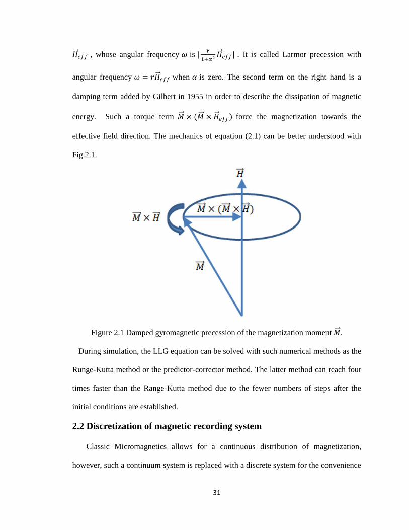
31
, whose angular frequency is
. It is called Larmor precession with
angular frequency when is zero. The second term on the right hand is a
damping term added by Gilbert in 1955 in order to describe the dissipation of magnetic
energy. Such a torque term force the magnetization towards the
effective field direction. The mechanics of equation (2.1) can be better understood with
Fig.2.1.
Figure 2.1 Damped gyromagnetic precession of the magnetization moment .
During simulation, the LLG equation can be solved with such numerical methods as the
Runge-Kutta method or the predictor-corrector method. The latter method can reach four
times faster than the Range-Kutta method due to the fewer numbers of steps after the
initial conditions are established.
2.2 Discretization of magnetic recording system
Classic Micromagnetics allows for a continuous distribution of magnetization,
however, such a continuum system is replaced with a discrete system for the convenience

32
of numerical simulation. Usually the soft magnetic material (such as write head and soft
under layer) is divided into uniform cubic or cells due the continuity of material [2.2].
However the hard magnetic material (such as the recording medium) is divided into the
irregular Voronoi cells considering the non-uniform material property and the similarity
to actual size distribution. The discretization of the magnetic recording system is
illustrated as Fig.2.2. In this simulation, the Voronoi construction which consists of
randomly distributed polygons on a plane is used for the grain morphology. The average
Voronoi grain diameter, standard deviation of diameter, nonmagnetic boundary spacing
and medium thickness can be adjusted for the simulation of the recording medium.
Figure 2.2 Discretization of a perpendicular magnetic recording system using a monopole
and Voronoi grains with soft underlayer [2.3].
2.3 Energy term and associated field
During the simulation, the total effective magnetic field in the LLG equation
consists of the anisotropic field , magnetostatic field , exchange field
and the external applied field . With them, the exchange field is short-range field,
while the magnetostatic field is the long-range dipole-dipole interaction requiring lots of
computation time. Without considering the magnetoelastic and surface anisotropy effects,

33
the total magnetic energy of a single domain grain when an external field is applied can
be shown in Eqn.(2.2),
(2.2)
where , , and are the magnetocrytalline anisotropy energy,
magnetostatic interaction energy, intergranular exchange coupling energy and Zeeman
energy.
Correspondingly, the effective field can be obtain by taking derivative of total energy
with respect to the magnetization , expressed as Eqn.(2.3),
(
)
(2.3)
Then every energy term and the associated field will be introduced in the next sections.
2.3.1 Magnetostatic energy
The magnetostatic potential is similar to the electrostatic potential: it can be derived
from as
(2.4)
Inside the material, )=0, satisfies Poisson’s equation as:
(2.5)
Then outside the material, the potential satisfies the Laplace’s equation as
(2.6)
The two boundary conditions for the potential with flux continuity are,
(2.7)
(2.8)

34
Then the solution for the potential is
∭ ( )
∬
( )
(2.9)
where and are the volume magnetic charge density and surface magnetic
charge density, respectively. and are the source and observation coordinates,
respectively.
Then by combining Eqn.(2.4) and (2.9), we can obtain the magnetostatic field as
Eqn.(2.10),
∭ ( )
∬
( )
(2.10)
In the simulation, the magnetization is uniform within the volume of the grain, i.e.
. Then the Eqn.(2.10) becomes as follows,
∬ (
)
| |
(
) ∑ (2.11)
where is the magnetostatic field felt by the ith grain, is the magnetization of
the jth grain , NG is the number of grains and is an interaction tensor from the jth
grain to ith grain, which can be expressed as Eqn.(2.12)
[
] (2.12)
When the magnetostatic field between the regular cubic discretization within the soft
magnetic material is calculated, the method proposed by Schabes Aharoni [2.4] can be
used. The method presented an exact analytic formula for the magnetostatic interaction
energy of a three-dimensional array of ferromagnetic cubes, and then exact formulas for
the effective magnetostatic interaction field can be derived based on the energy equation.

35
It is a quite convenient tool for three-dimensional micromagnetic calculation. When
magnetostatic field calculation is carried on for the hard magnetic material (such as
Voronoi shaped grains), there are two types of magnetostatic interaction due to the side
surfaces (rectangular shape) and the top and bottom surfaces (Voronoi shape), shown in
Fig.2.3. For the side surface, these rectangular sides are meshed into smaller rectangles,
and then the surface interaction is calculated. For the top and bottom surfaces, the
Jacobian integral technique [2.5] is used to map the irregular shape into a square for
surface integration calculation.
Figure 2.3 Magnetostatic interaction between two Voronoi grains.
2.3.2 Exchange coupling energy
Ferromagnetic materials have the characteristic of the strong interaction between
spins, which makes each spin tend to align or anti-parallel to the other surrounding spins.
Such an interaction was the origin of the “molecular field” hypothesized by Weiss, long
before the discovery of spin and quantum physics. Actually the spin-spin interaction
energy called the exchange interaction energy originates from the Pauli Exclusion
Principle in quantum physics and Coulomb electrostatic energy. The exchange
interaction of M atoms can be expressed with the Heisenberg Hamiltonian format as
Eqn.(2.13).
∑ (2.13)

36
where is the exchange integral, which is most significant for the nearest neighbor
electrons and decreases rapidly with increasing distance. for ferromagnetic
material, while for antiferromagnetic material, correspondingly the spins tend to
orient parallel and antiparallel for the ferromagnetic and antiferromagnetic material for
the minimum energy requirement, respectively.
In the micromagnetic simulation for the recording medium, the exchange coupling
energy between the nearest neighbor grains in the medium is calculated based on
Eqn.(2.13), and the expression is as Eqn.(2.14), where J is the exchange coupling
constant.
∑ (2.14)
For Voronoi shaped grains in recording media, the interfacial area between grains varies
due to the varying grain boundaries between every grain and its nearest neighbors.
Considering such an effect, the exchange energy between two grains is assumed to be
proportional to their interfacial area as the number of pairs of spins between the grains’
boundary is proportional to the interfacial area. Then the total exchange energy calculated
with Eqn.(2.14) should be modified as Eqn.(2.15),
∑
(2.15)
Where is the interfacial area between the ith grain and the jth grain, and is the
average side area if grains were hexagons. Then the corresponding exchange field at the
ith grain can be calculated as,
∑
(2.16)

37
Besides the energy expression in Eqn.(2.15)used for the hard magnetic material
(such as Voronoi grains), there is another exchange energy expression for continuous
magnetization which can be derived from discrete system using Eqn.(2.14) , and the final
exchange energy density is given as [2.6],
(2.17)
where
, a is the edge of unit cell, c=1,2 and 4 for a simple cubic, bcc and fcc
crystal structure respectively.
2.3.3 Magnetocrystalline anisotropy energy
It is found that the magnetization usually has a certain favorable direction (called the
easy axes) and an unfavorable direction (called the hard axes), which is called magnetic
anisotropy. Magnetocrystalline anisotropy is one of the magnetic anisotropies, which will
be discussed as follows. The reason for magnetocrystalline anisotropy is that in the
presence of a weak spin-orbit coupling, the magnetization will be coupled to electron
orbitals and thus have a lowest or highest energy along certain symmetry axes. For
magnetic recording, the magnetic material with uniaxial crystalline anisotropy (i.e. the
hexagonal close-packed structure) is used as the perpendicular magnetic recording media.
The uniaxial anisotropy energy density can be expressed as a power series of the form as
Eqn.(2.18),
∑ (2.18)
To the first order, the uniaxial anisotropy energy density can be approximated as
| | (2.19)

38
, where is the anisotropy energy constant (removing the constant term and
combing the effect of and into ), and are the easy axis direction and
magnetization direction, respectively. The effective anisotropy field can be obtained by
taking the derivative of the energy density with respect to the magnetization vector as
Eqn.(2.20),
(2.20)
Where
is called the anisotropy field.
2.3.4 Zeeman energy
The Zeeman energy is the magnetic energy of a grain under an applied field ,
which can be expressed as
(2.21)
Then the effective field can be derived as
(2.22)
2.3.5 Thermal fluctuation
The thermal disordering effect to magnetization can be described with a random
fluctuation field [2.7]. The basic assumption is that the thermal agitation effect
by a random process is that the random thermal forces have much shorter correlation time
(about 10-13
sec) than the response time (10-10
sec) of the magnetic system.
Correspondingly the Brownian motion can be used to describe the magnetization. And
the thermal agitation process can be expressed as Eqn. (2.23),
⟨
⟩ (2.23)

39
Where i,j=1,2,3, and
, V is the grain volume, symbol kB and T are the
Boltzmann constant and the temperature, respectively. The Dirac means the
autocorrelation time of the fluctuation field is much shorter than the response time of a
single-domain particle.

40
Chapter 3 Novel Reader Design for 10 Tbits/in2 User Areal
Density in Two Dimensional Magnetic System
3.1 Introduction
Various schemes for magnetic recording at user bit densities of 10 Tbits/in2
have
been proposed including two-dimensional magnetic recording (TDMR) [3.1], shingled
Bit Patterned Magnetic Recording (BPMR), and Heat Assisted Magnetic Recording
(HAMR), possibly in combination with BPMR. Individual bit dimensions at 10 Tbits/in2
are, at most, 8 x 8 nm, with substantially smaller values for those systems writing on
conventional media where raw error rates are likely to be very high. In particular,
TDMR attempts to store a channel bit in very few grains of a conventional magnetic
medium in order to achieve 1-1.5 data bits/grain [3.2],[3.3]. The irregular grain
boundaries and random distribution of grains produce extremely low signal-to-noise ratio
(SNR). Bit patterned media, by virtue of its regularity, is expected to alleviate some of
these issues, but is difficult to fabricate. All of these techniques will require read heads
capable of sensing this data, preferably with a single pass.
In a TDMR system, various 1-D and 2-D sub-optimal detectors have been used. An
inversion detector has been studied [3.4], and reasonable error rate performance was
reported. The maximum-likelihood (ML) and maximum a posteriori (MAP) detectors
based on the trellis or graph of the TDMR channels have been studied [3.5]. Huang and
Kumar [3.6] used a linear minimum mean squared error equalizer and a low density
parity check code to study the detection in a TDMR system.

41
In this chapter, a novel system design is proposed for reading two-dimensional
magnetic recording (TDMR) systems. The concept is also appropriate for other very high
density media such as BPMR. Based on a random Voronoi grain model, the simulation
indicates that for bits with dimension of 8nm×6nm, grains of 5.5nm diameter and reader
width of 18nm, the BER drops from 20.9% for a normally oriented head array to 4.2%
for a single rotated conventional head. A minimum mean squared error (MMSE)
equalizer and pattern-dependent noise prediction detector (PDNPD) with increased
sampling rate are used. The density is greatly increased to 10.1Tbits/in2. Furthermore,
density can be increased to 10.9 Tbits/Inch2 if the free layer width can be further reduced
by a factor 2.
3.2 The design of the reader
3.2.1 Previous read head array
Readback at high density requires exceptional resolution that, to date, has not seemed
possible using a single read head without multiple passes. Previously, we [3.3] employed
an array of read heads as shown in Fig.3.1. A threshold detector, combined with a two-
dimensional generalized partial response (GPR) equalizer using the MMSE criterion [3.7],
was designed for signals from the head array. This detection scheme was demonstrated to
work well. As it is known that the Viterbi detector based on ML sequence detection
outperforms the threshold detector with the symbol detection, a 1D Viterbi algorithm
(VA) was also used with a redesigned 2D partial response (PR) target. Here, a constraint
on the 2D GPR target that forces inter-track interference (ITI) to zero and keeps only the
controlled inter-symbol interference (ISI) was imposed in order to avoid the need for a
2D Viterbi algorithm.
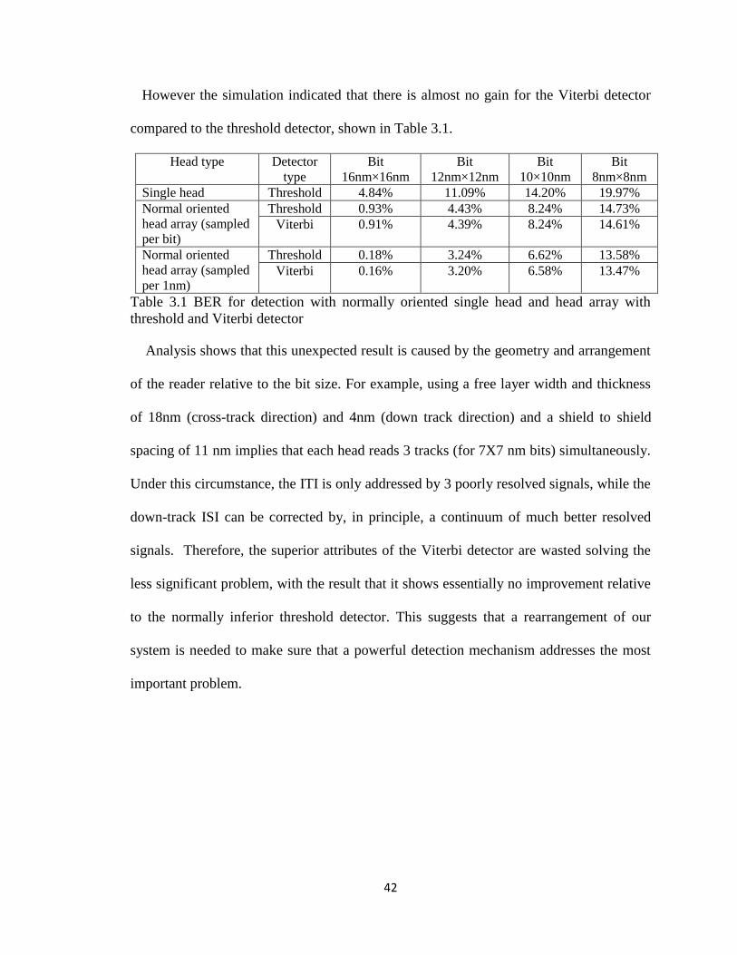
42
However the simulation indicated that there is almost no gain for the Viterbi detector
compared to the threshold detector, shown in Table 3.1.
Head type Detector
type
Bit
16nm×16nm
Bit
12nm×12nm
Bit
10×10nm
Bit
8nm×8nm
Single head Threshold 4.84% 11.09% 14.20% 19.97%
Normal oriented
head array (sampled
per bit)
Threshold 0.93% 4.43% 8.24% 14.73%
Viterbi 0.91% 4.39% 8.24% 14.61%
Normal oriented
head array (sampled
per 1nm)
Threshold 0.18% 3.24% 6.62% 13.58%
Viterbi 0.16% 3.20% 6.58% 13.47%
Table 3.1 BER for detection with normally oriented single head and head array with
threshold and Viterbi detector
Analysis shows that this unexpected result is caused by the geometry and arrangement
of the reader relative to the bit size. For example, using a free layer width and thickness
of 18nm (cross-track direction) and 4nm (down track direction) and a shield to shield
spacing of 11 nm implies that each head reads 3 tracks (for 7X7 nm bits) simultaneously.
Under this circumstance, the ITI is only addressed by 3 poorly resolved signals, while the
down-track ISI can be corrected by, in principle, a continuum of much better resolved
signals. Therefore, the superior attributes of the Viterbi detector are wasted solving the
less significant problem, with the result that it shows essentially no improvement relative
to the normally inferior threshold detector. This suggests that a rearrangement of our
system is needed to make sure that a powerful detection mechanism addresses the most
important problem.

43
Figure 3.1 Schematic of an array of three conventional MR heads on continuous media.
3.2.2 Rotated head design
The above discussion suggests that rotation of the read head, together with
oversampling in the down-track direction will greatly improve performance. The idea is
that resolution in the cross-track direction will be provided by tightly placed shields and
the resolution in the down-track direction (where large amounts of information can be
provided) will be given by signal processing. Here, we tried the new design with both a
single head, shown in Fig.3.2 (b), and a head array.

44
Figure 3.2 (a) Normal single head design; (b) Rotated single head design
In our new design, the conventional GMR-based read head has a shield to shield
spacing (SSS) of 11nm.The length of each head is taken to be 18nm, which is larger than
a bit length of 7nm.This permits easier fabrication and more thermal stability of the free
layer. The height of the head is 18nm. Here, we assume a magnetic fly height of 3nm, a
recording layer thickness of 10nm and a seed layer thickness between the SUL and
recording layer of 2nm.
We show that this approach combining a 90° rotation of the head, so that the inherently
narrow shield-shield spacing (usually used to gain downtrack resolution) blocks side read,
combined with oversampling in the down track direction to regain the lost resolution,
yields the required densities. Usually, it is assumed that the sampling rate is once per bit;
however there is no reason why the sampling rate cannot be increased if the cost is not
that high. Especially in a TDMR system, the extremely low SNR makes the increase of
sampling rate necessary to obtain more useful information about the signals from the
head. In this study, a sampling period of 2nm (f≈10GHz) or 3nm (f≈6.67GHz) is
reasonable when the average rotation speed for the hard drive is assumed as 20m/s.
Besides the severe media noise, we also included the Johnson noise and magnetization
noise as head noise. The magnetization noise of the GMR reader can be estimated by
eq.(7) in [3.8]. We assume P=Ib2R, MR ratio ∆R/R = 15%, free layer stiffness Hstiff =
10Oe, damping constant α =0.01, gyromagnetic ratio γ = 17.6 Mrad/(s Oe), free layer
magnetization Msf =1600 emu/cm3, resistivity 𝜌 equals 20 uΩ·cm, and biasing current
Ib=5mA. The Johnson noise can be estimated as Eqn.(3.1), [3.9]
(3.1)

45
The “efficiency” є is around 0.2, is the bandwidth of signal. The calculated SNR
for various sampling periods is shown in Table 3.2.
Table 3.2 Noises for various sampling periods.
3.3 Detection schemes with the new head design
3.3.1 Detection system architecture
During the writing process, a perfect writer has been used based on a Voronoi grain
model [3.10], where a Voronoi grain is magnetized by the channel bit containing the
centroid of the grain cell. Playback signals for the conventional MR head are numerically
evaluated using the reciprocity principle applied to a potential acquired from a finite
difference code [3.10], [3.11]. The reciprocity principle states that the playback signal is
equal to the convolution of the head magnetic potential and the written magnetization
pattern on the recording media, expressed as Eqn.(3.2).
∫
(3.2)
We assume composite media whose hard layer includes a synthetic antiferromagnet
[3.12]. Thus the voltage can be obtained by subtracting the head potential at the hard/soft
interface from the potential at the top of the recording media.
The design of our detection system is shown in Fig. 3.3. Although the system is
similar to common channel models, there are a few obvious differences. First, most
previous research on detection has not included the head design and the relationship
Sampling period 6 nm 3nm 2nm
Bandwidth of Signal (GHZ) 3.33 6.67 10
Magnetization noise (SNR/dB) 30.7 27.7 26.0
Johnson noise(SNR/dB) 23.1 20.1 18.3
Total noise(SNR/dB) 22.4 19.4 17.6

46
among the head, equalizer and detector: however, we have proposed a new head design
and tried to exploit the relationship between these factors. Additionally, unlike most
previous work, we obtain the playback signals using the reciprocity principle instead of a
channel model with read sensitivity function. Furthermore, it’s usually assumed [3.7] that
the channel samples each bit once: we find the BER will drop significantly if sampling
rate is increased during the scan of this proposed head. Last but not least, previous
research has usually assumed the media and reader noises as Gaussian and varied the
SNR without physical basis: however, in our model, the media noise is controlled by
varying the number of grains per bit in the Voronoi model, and reader noise is taken to be
flat band-limited noise with SNR dependent on data rate and free layer volume, according
to accepted physical models [3.8],[3.9].
Figure 3.3 Schematic of the detection system architecture.
3.3.2 Detection with rotated single head
For a rotated head, the ISI is more severe than ITI. We combat the ISI with a 1D
equalizer and an improved Viterbi detector; In the cross-track direction, the shields are
utilized to combat the ITI. For the design of the 1D MMSE equalizer [3.13], we make the
target of size 1×3, namely the length of ISI is 3. This constraint can be shown as
g =[1,g1,g2] (3.3)
The constraint can be expressed as eq.(3.4),where c=1 and E=[1,0,0]T.
ETg=c (3.4)

47
Here the monic constraint (g0=1) is adopted for its optimal target shape. Then the
optimized target and equalizer coefficient vector can be obtained with Eq. (3.5), (3.6) and
(3.7).
(3.5)
(3.6)
(3.7)
We choose a target of size 1×3 and equalizer of size 1×15×(bit length/2) or 1×15×(bit
length/3) for a sampling period of 2 or 3nm. The playback signals calculated using the
reciprocity principle are considered to be the channel output signals y, the channel input
data is a. Hence, the auto-correlation matrix of the channel output R, the cross-correlation
of the input data and the channel output data T, and the auto-correlation of the input data
A can be expressed as R=E{ykykT}, T={ykak
T} and A={ akak
T }.
The Viterbi detector in the partial response maximum likelihood (PRML) system is
optimal in the presence of additive white Gaussian noise (AWGN). Media noise, which is
nonstationary, correlated, and data-dependent, can cause serious performance degradation
in a TDMR system when compared to a system operating with the same amount of
AWGN. Correspondingly, a data-dependent full local feedback noise prediction schemes
[3.14] has been adopted for the rotated single head in our TDMR system. In this scheme,
the Viterbi detector recursively updates the cumulative metrics for each state using the
update equations (3.8),
∑
(3.8)
where is the cumulative metric associated with state s at time k-1, are the
coefficients of the finite impulse response polynomial for the partial response channel,

48
are the data bits on the surviving path leading to s, is the branch-dependent
prediction of the noise, and
∑
. (3.9)
Here, are the K data bits on the surviving
path leading to s together with the data bits associated with the branch . The taps of
the noise prediction filter depend on and are the solution of the
Yule-Walker equations, similar to Eq.(8) in Ref. [3.14]. Here, we choose data dependent
length K within the range of 5 and 7 depending on bit size, the noise predictor length L=8.
In our rotated head array design, ISI and ITI can both be addressed using 2-D
equalization and detection as originally envisioned for TDMR. By imposing a constraint
on the 2D target that forces ITI to zero and keeps only the controlled ISI, the
conventional VA can handle ISI well. If we make a target of size 3 ×3, namely the length
of ISI and ITI are 3, these constraints are similar to Eq.(15) to (19) in Reference [3.7].
Then the optimized target and equalizer coefficient vectors can still be obtained with Eq.
(5), (6) and (7). Here we choose the target of size 3×3 and equalizer of size 3×15×(bit
length/2) or 3×15×(bit length/3) when sampling period is 2 or 3nm.
3.4 Numerical evaluation
Results for a rotated single head (RSH) are shown in Table II for a center-to-center
grain size (grain pitch) of 5.5 nm with standard deviation of 20%. Here every result is
the average of 25 trials with each trial having a different 10500 bits PRBS. Error bar are
0.1%. The results indicate that BER is reduced with a PDNPD compared to a Viterbi
detector owing to the embedding of the data dependent prediction of the noise into the
branch metrics. For bits of dimension 9nm x 10nm and 8nm grains, the BER can drop

49
from 15.73% for a normal head array (NHA) to 1.67% for RSH for 2nm sampling. It can
also be seen that oversampling is crucial: sampling once per bit increases BER by about a
factor 2 despite the decrease in head noise owing to the decreased bandwidth. (This
oversampling could be replaced by long channel target length, but at considerable
detector expense.) The data densities can be calculated using the Shannon Capacity limit
[3.15] by assuming the magnetic channel as Binary Symmetric Channel (BSC) and
allowing a very long codeword, expressed as Eqn.(3.10) and (3.11).
( ) (3.10)
User Density= (3.11)
For 8 nm grains, the user data density reaches around 6.3 Tbits/inch2. The user density
increases to 10.1Tbits/in2 for the same head when the grain size is decreased to 5.5nm, as
shown in Table 3.3. We believe this to be the highest simulated density ever
demonstrated. We find that, when the bit size is comparable to the shield to shield
spacing, the ITI is insignificant compared to the media noise.
We have also examined the tradeoff between head noise and sense head dimensions.
Results for several head widths are shown in table 3.4, where a bit size of 8×6nm is used.
It can be seen that smaller dimensions, if they can be fabricated, will increase user
density despite the increase in noise from thermal fluctuations.
Bit size 5×10nm 6×8nm 7×7nm 8×6nm 9×6nm 8×7nm
BER(NHA,VA) 23.7% 22.7% 21.5% 20.9% 17.8% 20.1%
BER (RSH,VA ) –bit sampling 15.2% 11.5% 8.7% 8.4% 6.8% 5.9%
BER(RSH,VA )-3nm sampling 9.8% 6.3% 5.9% 5.7% 5.2% 4.1%
BER(RSH,VA ) -2nm sampling 9.7% 5.9% 5.0% 4.7% 3.7% 2.9%
BER(RSH,PDNDP ) 9.6% 5.7% 4.6% 4.2% 3.3% 2.4%
Density(NHA,VA)Tbits/in2
2.7 3.1 3.3 3.5 3.9 3.2
Density(RSH,VA)Tbits/in2
7.0 9.1 9.4 9.8 9.2 9.3
Density(RSH,PDNDP) Tbits/in2
7.0 9.2 9.6 10.1 9.4 9.6

50
Table 3.3 BER for both single head with Viterbi Detector and PDNPD for 5.5nm grain
Table 3.4 BER for various head widths
We have extended our simulation to include an array of rotated heads (RHA) with
oversampled signals. Tables 3.5 and 3.6 show that this approach greatly reduces BER
compared with a normal head array, but there is only a small overall improvement of user
density compared to a single rotated head.
Table 3.5 BER for both head arrays for 8nm grain.
Table 3.6 BER for both head arrays for 5.5nm grain.
In the previous section, a novel system design for sensing very high density magnetic
recording data is investigated. The rotated single head with oversampled signals, MMSE
equalizers and PDNPD has been proposed, and the BER can be decreased compared with
a normally positioned head array, increasing density to 10 Tbits/inch2. Also a rotated
head array reaches slightly better performance compared to a single rotated single head.
While demonstrated for conventional media, this system design should also be very
Head width 24nm 18nm 12nm 9nm
BER(RSH,PDNDP ) 5.6% 4.2% 3.3% 2.9%
Density(RSH,PDNDP) Tbits/in2 9.3 10.1 10.7 10.9
Bit size 8×10nm 9×9nm 10×8nm 9×10nm
BER(RHA,VA ) 4.2% 3.8% 6.5% 1.5%
BER(NHA,VA ) 19.7% 16.6% 11.8% 15.7%
Density(RHA,VA) Tbits/in2 6.0 6.1 5.3 6.4
Density(NHA,VA) Tbits/in2 2.3 2.8 3.8 2.7
Bit size 5×10nm 6×8nm 7×7nm 9×6nm 6×9nm
BER(RHA,VA ) 3.8% 3.8% 4.7% 3.4% 1.5%
BER(NHA,VA ) 23.7% 22.7% 21.5% 17.8% 22.4%
Density(RHA,VA) Tbits/in2 9.9 10.3 9.6 9.4 10.6
Density(NHA,VA) Tbits/in2 2.7 3.1 3.3 3.9 2.8

51
useful for BPMR.
3.5 Study on response of various reader designs
In the previous section, we proposed a novel system design for readback at ultra-high
density from granular media [3.16] with perfect writing: the key idea involves use of a
rotated sense head, so that the shields are aligned down-track, and oversampled signal
processing is used to regain the lost down-track resolution. However, our previous studies
have focused on the detector, and did not consider any coding scheme. Additionally, the
previous research [3.16] only tried to explain improvements brought by the new design
from a geometric viewpoint, but understanding from the signal processing perspective is
still needed.
In this study, we present and explain the performance of rotated and normally oriented
heads from a signal processing perspective, and examine the performance of various
coded designs by varying the bit-aspect ratio (BAR) using the quasi-cyclic low-density
parity-check (QC-LDPC) code [3.17] with codeword length of 4096 bits. First, the linear
responses for TDMR system readback with both normally and rotated heads are studied.
The read head sensitivity (RHS) response of the realistic reader calculated using the
physically accurate reciprocity principle is also analyzed. Based on the channel model, a
linear minimum mean square error (LMMSE) equalizer is employed for equalization and
a QC-LDPC decoder is used for error corrections. Meanwhile the possible channel
capacities reached by various readers are studied, and the performance discrepancies
among various decoded systems are compared. The simulation indicates that with an
oversampled signal, 2D LMMSE equalizer and LDPC codes, a user bit density near 10
Tbit/in2 is feasible for a rotated head array.

52
3.5.1 Linear responses of various readers
Previously, a rotated reader design shown in Fig.3.2 (b) combined with oversampling
signal processing was proposed for readback at ultra-high density from both granular
media [3.16] with perfect writing. Here, a conventional giant magnetoresistance (GMR)-
based head is used, and the dimension of the free layer is 18nm × 18nm ×4nm, shield-to-
shield spacing is 11nm and magnetic fly height is 3nm. Perfect writing is used to write a
pseudo-random binary sequence (PRBS) on 10nm thick exchanged coupled composite
(ECC) media with 5.5 nm Voronoi grains, where a Voronoi grain is magnetized by the
channel bit containing the centroid of the grain cell. For readback, the physically accurate
reciprocity principle [3.11] is used by convolving a head potential from a finite difference
code [3.10] with the divergence of media magnetization to obtain the playback signals for
the GMR head, shown as Eq.(3.2). Then the readback signal is considered as the channel
output, and a 1-D LMMSE equalizer is employed for equalization.
In order to characterize the system’s linear response that shows the spatial resolution
along the down track direction, the dibit extraction technique [3.18] is utilized, which
uses the cross-correlation of a PRBS and the playback waveforms, expressed with
Eqn.(3.12). The benefit of such a method is that it does not require any timing
information about the signal other than the period of the PRBS. Here the x7+x
3+1 PRBS
sequences are used to write 8nm ×8nm bits during the writing process.
∑
(3.12)
where N=127 is the length of PRBS, is the cross correlation of readback signal and
PRBS.
We compared the dibit responses for a given PRBS of a normally oriented singled

53
head (NSH) without adjacent track interference (ATI), and a NSH and a rotated singled
head (RSH) with ATI, shown as Fig.3.4. All the geometric and physical parameters are
the same for both NSH and RSH.
Figure 3.4 Normalized dibit responses along the down-track direction for the normally-
oriented head with and without ATI and rotated single head with ATI (Normally oriented
head with no ATI closely overlaps rotated head with ATI).
Fig.3.4 indicates that the amplitude of the dibit response of the normally oriented
single head (NSH) decreases due to the adjacent track interference (ATI) compared to the
case without ATI. However, the rotated single head yields a normalized dibit response
that is equal to that of the ATI free signal from the normally oriented head. It means that
the RSH can successfully resolve an 8nm track with ATI, even though the free layer
length (18nm) is much wider than the current track (8nm).
3.5.2 Read head sensitivity response
Previous research [3.5], [3.19] assumed a 2-D Gaussian profile for the head response
with a symmetric T50 (defined as the time for the step response to go from 25% to 75% of
its maximum) along both down track and cross track directions. Correspondingly, the 2-D
MAP detector outperformed the 1-D MAP detector, since the former one treats ITI as
useful information to help the decision while the latter one treats ITI as noise. However,

54
the actual situation is different owing to the read head sensitivity (RHS) response
obtained with the physically accurate reciprocity principle for the rotated single head,
shown as Fig.3.5. The RHS response is obtained with the reader design in Fig.3.2 (b) for
readback of 8nm×8nm bits.
Figure 3.5 Read head sensitivity response for rotated head in the simulation.
It is easy to show that the T50 along the down track direction is much larger than that
along the cross track direction based on Fig.3.5. The calculation for the step responses
along both directions indicate that T50down-track≈ 2.6T50cross-track, which also means the ISI is
much more severe than ITI for the low bit aspect ratio (BAR) case. Reference [3.5]
indicates that the performance of a 1-D detector is comparable to the much more
computationally-intensive 2-D detector when ITI turns out to be significantly smaller
than ISI. Correspondingly, the ITI and ISI can be treated differently in the channel. If the
ITI is negligible for the rotated head when the track width is large, then the narrow shield
to shield spacing along the down track direction is sufficient to guarantee the resolution
along the cross track direction. If the track width is further decreased, e.g., 8nm, the
rotated head array combined with 2-D equalization which forces the ITI to be zero can
55
still lead to satisfactory results [3.16] because the ITI is still much smaller than ISI as
suggested by Fig.3.5. Hence the fundamental reasons for the rotated head design are: (1)
the geometry of the normally oriented head makes ITI much worse than ISI for low BAR
cases, which are inevitable for extremely high channel density; (2) the inability of a
normally oriented head array to adequately sample in the cross-track direction to
compensate for the poor resolution makes the performance inferior.
3.6 Signal processing and performances comparisons for various
readers
3.6.1 The channel capacities for various readers
Previous research [3.5] indicates that the performance of an inversion detector is
close to the superior 2-D MAP detector at high densities due to the predominant role of
media noise compared to the insignificant additive electronic noises. In this study,
considering the convenience of obtaining the log likelihood ratio (LLR) for LDPC codes,
a LMMSE equalizer is used to take into account the random distribution of grains within
the bit cells. The LMMSE equalizer can be derived as Eq.(3.13).
(3.13)
Correspondingly the mean squared error between channel input, {xi,j}, and the
equalized output, {(y*f)i,j} is minimized. Here y is the output of the channel, f are
equalizer coefficients, and E [•] denotes the expectation. For a normally oriented single
head, a 1-D equalizer of size 1 × [15 × bit length/2nm] is adopted for a sampling period
of 2nm, where the target size is 1×3. For both normally oriented and rotated head array, a
2-D equalizer of size 3× [15 × bit length/2nm] is used when the sampling period is 2nm,
where the target size is 3×3.The block diagram of the TDMR channel architecture is
shown as Fig.3.6. Perfect writing is used to shingle write a channel density of about 12

56
Tbits/in2.There is a 1D to 2D converter in the TDMR architecture that simply wraps a 1D
codeword into a 2D block to prepare for the shingled writing process.
Figure 3.6 Block diagram for LDPC-coded TDMR system.
The reader noise is taken to be flat-band-limited noise with SNR dependent on the
data rate and free layer volume, according to the accepted physical models. The
magnetization noise and Johnson noise are both included in the head noise. The reader
SNR for sampling per 2nm is about 18 dB. Varying the BAR varies the amount of ITI
and ISI introduced by the readers and it also affects the writing performance of the writer.
Correspondingly, during simulation, the BAR is varied to obtain the optimum
performance for each system. The bit error rate (BER) is obtained for various readers
from the simulation and is shown in Fig.3.7. Simulation indicates that the BER for the
rotated head array (RHA), normally oriented head array (NHA) and NSH are about 2.7%,
9.3% and 12.0% for their optimum BARs of 0.67, 3.5 and 3.5, respectively. Clearly
avoiding the effect of interference along both down and cross track directions are major
concerns for both RHA and NHA: it is clear that the optimum BARs for both heads
should appear at lower ratio(<1) and higher ratio(>2), respectively, due to the
arrangements of the heads along different directions.

57
Figure 3.7 BER for various reader designs.
The channel capacities for various systems can be calculated with the Shannon
Capacity limit according to the BER obtained in the simulation by assuming the
recording channel to be a Binary Symmetric Channel (BSC). The maximum capacities
(user bits/Channel bits) for these cases correspond to 0.821, 0.554 and 0.471, or areal
densities of 9.85T/in2, 6.64T/in
2 and 5.65T/in
2, respectively, as shown in Fig.3.8.

58
Figure 3.8 Capacity (user bits/channel bits) for various systems.
3.6.2 Performances for various coded systems
The conditional probability density functions (pdf) of equalized outputs for various
systems can be obtained by simulation, as shown in Fig.3.9. In Fig.3.9, it is interesting to
find that the overlap between conditional pdfs, which is usually reduced by using
constrained codes with the penalty of reducing recording rates, is reduced by the RHA
compared to the NHA. Correspondingly, we can derive that BER will be reduced by the
RHA from the decreased overlap between conditional pdfs. Both curves have additional
contributions that are caused by the unwritten bits (if no grain centroid falls within the bit)
and residual interference. The unwritten bits will cause residual errors after the LMMSE
equalization, because the mean of the equalizer output E[y*f LMMSE
] could be zero for the
unwritten bits due to the independence of (y*fLMMSE
) from . However, for written bits,
E[y*fLMMSE
] = because the effect on the channel inputs, caused by the random
placement of grains and additive noises, were cancelled out in the averaging.
Based on the conditional probability density, the log likelihood ratio (LLR) can be
obtained for the equalized data, from Eq. (3.14)
(3.14)
where z=(y*f LMMSE
) is the LMMSE equalizer output, f-1(z) and f1 (z) are the conditional
probabilities density of z given x= -1 and x=1.

59
Figure 3.9 Conditional probability density function of equalized output for both rotated
and normally oriented head array.
This LLR is then used as the soft input for quasi-cyclic LDPC (QC-LDPC) decoding,
whose codeword length is 4096 bits. The reason for using QC-LDPC codes in this system
is that its quasi-cyclic structure leads to simpler hardware design of decoders. After
decoding, we observed the waterfall region with LDPC code of rate 0.8125 for the RHA,
while such a code rate does not work for the NHA and NSH, shown in Fig. 3.10.When
the code rate for the NHA is reduced to 0.55, its performance is still about 8.5dB worse
than the RHA with code rate of 0.81, shown as Fig.3.10. This demonstrates the feasibility
of user bit density near 10 Tbits/in2 for the rotated head array. Notice that the layered
algorithm [3.20] with maximum number of iterations equals 30 is adopted as the
decoding approach in the above simulations. It is important to note that the simulations
for both Fig.3.10 and Fig.3.11 are carried on with Voronoi model, and the SNR labeled in
both figures are only head and system noises relative to the long wavelength signal.
Correspondingly the simulation has included both media noise (already included in
Voronoi model), head and system noise for Fig.3.10 and Fig.3.11.

60
Figure 3.10 BER for various quasi-cyclic LDPC coded systems with code rate 0.8125 as
a function of head and system SNR.
Figure 3.11 BER for various quasi-cyclic LDPC coded systems with different code rates
as a function of head and system SNR.
3.7 Conclusion
In this chapter, a novel system design for sensing very high density magnetic recording
data is investigated. The rotated single head with oversampled signals, MMSE equalizers
and PDNPD has been proposed, and the BER can be decreased compared with a
normally positioned head array, increasing density to 10 Tbits/inch2. Additionally, the

61
performance of rotated and normally oriented heads are presented from a signal
processing perspective, and the performance of various coded designs are examined with
the quasi-cyclic low-density parity-check (QC-LDPC) code in a two-dimensional
magnetic recording (TDMR) system. The study indicates that the significant
improvement of performance of the rotated head compared to the normally oriented head
can be attributed to the larger amplitude of its dibit response and the reduced overlap
between conditional probability density functions (pdfs). With an oversampled signal, 2D
LMMSE equalizer and LDPC codes, a user bit density near 10 Tbit/in2 is feasible for a
rotated head array.

62
Chapter 4 System Design for Readback above 1 Terabit/Inch2
from Granular Media
4.1 Introduction
To overcome the superparamagnetic limit faced in conventional recording media,
several novel system architectures have been proposed, such as bit patterned media
recording (BPMR), heat-assisted magnetic recording (HAMR) and two-dimensional
magnetic recording (TDMR) [4.1]. TDMR attempts to store approximately one channel
bit per grain on conventional media, causing the raw error rate to be very high. It is
supposed to be implemented with shingled writing (SW) and two-dimensional readback.
In a TDMR system, the irregular grain boundaries, random distribution of grains and very
few grains per bit produce extremely low signal-to-noise ratio (SNR). Furthermore, the
severe inter symbol interference (ISI) and inter track interference (ITI) generate
significant challenges for readback.
In a TDMR system, various 1-D and 2-D sub-optimal detectors have been used. An
inversion detector has been studied [4.2], and reasonable error rate performance was
reported. The 2-D and 1-D maximum a posteriori (MAP) detectors have been studied and
compared in [4.3]. Huang and Kumar [4.4] used a linear minimum mean squared error
equalizer and a low density parity check code to study the detection in a TDMR system.
Previously, we have proposed a novel system design for readback at 10 Tbits/in2
user
areal densities on conventional media [4.5]. The key idea is a rotated sense head, so that
the shields are aligned down-track, combined with oversampled signal processing to
regain the lost down-track resolution. Based on a random Voronoi grain model,
simulation indicates that for bits with dimension of 8nm×6nm, 5.5nm grains, and a reader

63
with 4nm x 18nm x18nm free layer and 11 nm shield-shield spacing, the bit error rate
(BER) is a factor 5 smaller for a single rotated head than for a normally oriented head
array. The user density computed using the Shannon capacity limit, is greatly increased to
10.1 Tbits/in2, that, however, allows very long code word length and assumes a binary
symmetric channel.
In this paper, we vary the parameters of the proposed head design systematically for
various channel densities. Then the performance of the rotated single head (RSH) and
rotated head array (RHA) are compared with that of a normally oriented single head
(NSH) at optimized bit aspect ratio (BAR). We also test the effect of head noises,
magnetic fly height (MFH) and shield to shield spacing (SSS) on the performance of
several designs.
4.2 Reader design
4.2.1 Principle and structure of reader
The premise of the rotated head design (Fig.4.1) is that ITI is a worse problem than ISI
because 1) the geometry of a normally oriented head makes the ITI much worse than ISI
for low bit aspect ratio case, which is inevitable for high channel density and 2) ITI and
ISI are treated differently in the channel owing to the inability to adequately sample in
the cross-track direction. It is known that a 2-D detector shows advantage over a 1-D
detector because the former treats ITI as useful information while the latter one treats it
as noise. However the 2-D detector is more computationally expensive, especially for
large sector size and will cause latency owing to the need for information from several
adjacent tracks [4.3]. By minimizing the unwanted effect of ITI, the rotated head design

64
can avoid the necessity of complex 2-D detectors, and reach similar or even better
performance.
Figure 4.1(a) Normal single head design. (b) Rotated single head (RSH) design.
4.2.2 Parameters for simulation
Much of this study assumes that the size of a reader decreases when the channel bit
density is increased in order to obtain reasonable resolution. Here a conventional giant
magnetoresistance (GMR) based head is used, and the free layer (FL) dimension, shield
to shield spacing (SSS), and magnetic fly height (MFH) have been varied for various
channel densities, as shown in Table 4.1. This shrinking appears feasible over the next 5-
10 years although the reduction of the shield to shield spacing may require novel
approaches such as a scissor structure [4.6]. The same parameters are applied to both
rotated and normal head when the channel density is the same.
Channel bit density (Tbit/in2) 1 2 3 4 5 7
FL Width/Height (nm) 30 27.5 24.5 22 21.5 20
FL Thickness (nm) 5 5 5 4 4 4
MFH (nm) 7 6.5 5.5 5 4.5 4
SSS (nm) 16 15 14 13 12.5 12

65
Table 4.1 Geometric parameters of read head for various channel bit densities
Besides the head parameters mentioned above, the recording layer thickness is 10nm
and the seed layer thickness between the soft under layer (SUL) and recording layer is
2nm. In the simulation, average grain pitch of 8nm with standard deviation of 20% is
used; hence, the corresponding relation between the grains per channel bit and channel bit
density is shown as Table 4.2. In this model, the media noise is controlled by varying the
number of grains per bit in the Voronoi model, and the reader noise is taken to be flat
band-limited noise with SNR dependent on data rate and free layer volume, according to
accepted physical models [4.7],[4.8]. The magnetization noise and Johnson noise are both
included in the head noise. Correspondingly, the reader noises for the various free layer
dimensions and sampling periods are calculated in Table 4.3, where reader type (labeled
from 1 to 7) corresponds to the reader described in Table 4.1 for channel densities
ranging from 1 Tbit/in2 to 7 Tbits/in
2. It is found in Table 4.3 that the decrease of free
layer volume and sampling period both decrease the reader SNR, where SNR in dB is
shown for reader noise relative to long wavelength signal.
Grains per channel bit 12.8 6.4 4.2 3.2 2.5 1.8
Channel bit density (Tbit/in2) 1 2 3 4 5 7
Table 4.2 Relation between grains per channel bit and channel bit density
Table 4.3 Noises for various readers and sampling periods.
4.2.3 Detection with designed head
During the writing process, a perfect writer has been used based on a Voronoi grain
model [4.9]. For reading back, the reciprocity principle [4.10] is used by convolving a
Reader Type 1 2 3 4 5 7
Sampling per 10 nm (SNR/dB) 31.0 29.2 27.8 27.1 26.5 26.1
Sampling per 2nm (SNR/ dB) 24.0 22.3 20.9 20.2 19.5 19.2

66
head potential from a finite difference code [4.9] with the divergence of media
magnetization to obtain the playback signals for the GMR head.
The playback signals calculated using the reciprocity principle are considered to be
channel output signals, which have been processed with a moving average filter before
going through the equalizer. For both rotated and normal single heads, the 1D MMSE
equalizer is used, and its size is 1×15 or 1× [15× for a sampling period
of 1 bit or 2nm, respectively. The size of the 1D target is 1×3, and the monic constraint is
adopted whose first coefficient is 1.
For a head array, the 2D general partial response (GPR) target that forces ITI to zero
and keeps only the controlled ISI is adopted; with size is 3×3. We choose a 2D equalizer
of size 3×15 or 3× [15× for the rotated head array when the sampling
period is 1 bit or 2nm.
After both 1D and 2D equalizers, a conventional Viterbi detector is implemented. In
principle, such a detector is sub-optimal since the media noise is nonstationary, correlated
and data-dependent, and the performance could be improved with a more sophisticated
noise prediction algorithm. However, it will entail a significant increase in complexity
and thus computational time owing to the extensive amount of data presented in this
paper. Furthermore, our previous work shows that a Pattern Dependent Noise Prediction
Detector only enhances BER by a small factor [4.5].
4.3 Numerical evaluation
4.3.1 Optimum bit aspect ratio for various readers
For both the rotated and normally oriented head, the same head parameters are
adopted, and the bit aspect ratio (BAR) is varied for each channel density to obtain the

67
optimum results for each. As the bit aspect ratio is not limited by the fabrication process,
it can be alternated by varying the timing of writing current. In simulation, the BAR
varies within the range of 5:1 to 1:3 depending on the channel density. We examined
BER as a function of BAR for channel density ranging from 2 to 7 Tbits/in2
as shown in
Figure 4.2 to 4.6. Owing to the relatively small target and the large inter-symbol
interference, each plot also displays the benefits of oversampling.
Figure 4.2 BER vs. BAR for various heads and sampling periods at 2 Tbits/in2 channel
bit density.
Figure 4.3 BER vs. BAR for various heads and sampling periods at 3 Tbits/in
2 channel
bit density.

68
Figure 4.4 BER vs. BAR for various heads and sampling periods at 4 Tbits/in2 channel
bit density.
Figure 4.5 BER vs. BAR for various heads and sampling periods at 5 Tbits/in2 channel
bit density.

69
Figure 4.6 BER vs. BAR for various heads and sampling period at 7 Tbits/in2 channel bit
density.
According to Figure 4.2 to 4.6, it is found that the rotated single head outperforms the
normally oriented head at all densities other than 2 Tbits/in2 channel bit density at bit
sampling with high BAR; the lowest BER reached by the former one is decreased about
an order of magnitude compared to the latter case. Oversampling shows no obvious
improvement for the NSH at any channel bit density, while the benefits of oversampling
seems more obvious for the RSH when channel bit density is increased.
We also find that the optimized BAR for the NSH is large, i.e. above 2, while the
optimized BAR for the RSH is around 1. The reason for this is that varying BAR means
varying the amount of interference introduced by the reader in both downtrack and cross
track directions. For the normally oriented single head, avoiding the effect of ITI is a
major concern; correspondingly a high BAR is preferred. In contrast, the rotated single
head addresses the two types of interference with approximately the same effectiveness;
hence a nearly square bit becomes optimal. Figure 4.7 also shows the optimized BAR for

70
a rotated head array. Owing to the enhanced treatment of the ITI using 2D equalization,
the optimized BAR becomes less than 1.
Figure 4.7 Optimum bit aspect ratio for various heads.
4.3.2 BER VS grains per channel bit
After we obtain the optimum performance for the NSH, RSH and RHA cases, it is easy
to obtain the optimum BER as function of grains per channel bit, shown as Figure 4.8 and
Figure 4. 9.
Figure 4.8 BER vs. grains per channel bits for various heads with sampling per bit.

71
Figure 4.8 and 4.9 indicate that the RSH always outperforms the NSH for various
channel densities independent of whether sampling per bit or per 2nm is used.
Furthermore, oversampling can greatly decrease BER for the RSH compared to sampling
per bit, while it shows little improvement for the NSH. When sampling per bit, the RSH
and the RHA can provide 1.3X and 1.9X density gain compared to the NSH for target
BER of 10-3
. It is also found that the RSH and the RHA with a sampling period of 2nm
can provide 1.7X and 2.1X density gain compared to the NSH, respectively. The choice
of RHA with sampling per bit or RSH with sampling per 2nm will apparently depend on
the feasibility of array fabrication versus high frequency detection.
We also find that the rotated head design can decrease BER greatly compared to a NSH
at quite high density, such as fewer than two grains per channel bit. Such performance
has not been obtained with a 2-D MAP detector at these densities: it shows little
improvement over a 1-D detector and maintains BER around 20% [4.3]. With our new
design, the rotated head array can decrease BER from 17% for a NSH to around 3% for
1.84 grains per bits; correspondingly the user density calculated with Shannon Capacity
is greatly increased from 2.5Tbits/in2 to 5.8Tbits/in
2.
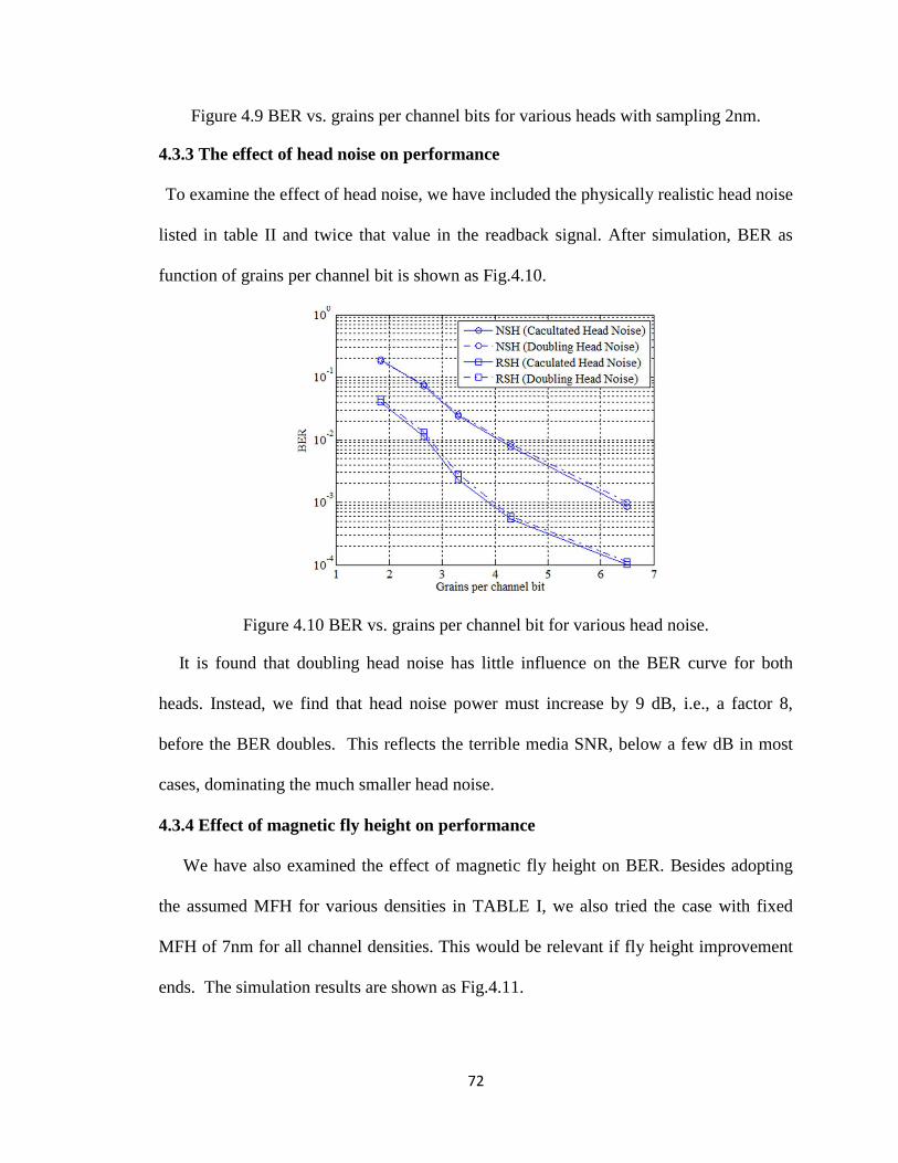
72
Figure 4.9 BER vs. grains per channel bits for various heads with sampling 2nm.
4.3.3 The effect of head noise on performance
To examine the effect of head noise, we have included the physically realistic head noise
listed in table II and twice that value in the readback signal. After simulation, BER as
function of grains per channel bit is shown as Fig.4.10.
Figure 4.10 BER vs. grains per channel bit for various head noise.
It is found that doubling head noise has little influence on the BER curve for both
heads. Instead, we find that head noise power must increase by 9 dB, i.e., a factor 8,
before the BER doubles. This reflects the terrible media SNR, below a few dB in most
cases, dominating the much smaller head noise.
4.3.4 Effect of magnetic fly height on performance
We have also examined the effect of magnetic fly height on BER. Besides adopting
the assumed MFH for various densities in TABLE I, we also tried the case with fixed
MFH of 7nm for all channel densities. This would be relevant if fly height improvement
ends. The simulation results are shown as Fig.4.11.

73
Figure 4.11 BER curve for various MFHs with both heads.
Figure.4.11 indicates that keeping a large magnetic fly height has increased the BER for
both a normally oriented single head and rotated single head. The performance
discrepancy between the two fly heights increases with decreased grains per bit,
especially for the rotated single head down to 3 grains per bit. The reason is that the
increased difference between fixed 7nm MFH and the previous assumed MFHs in Table
4.1 causes a wider readback waveform. The decreased bit size also brings more severe
ITI. The problem can be solved with a rotated head array that addresses the ITI by
detecting information from adjacent tracks with the side heads and 2D equalization, as
shown in Figure 4.12.
It can be seen in Fig.4.12 that a rotated head array with 7nm MFH can reach almost
the same performance as the rotated single head with the smaller MFH listed in TABLE I.
Correspondingly, the rotated head array shows an advantage over a single rotated head
when the constraint on MFH is loosened. Therefore, its greater difficulty of fabrication
may be worthwhile if magnetic fly heights do not decline in the future.
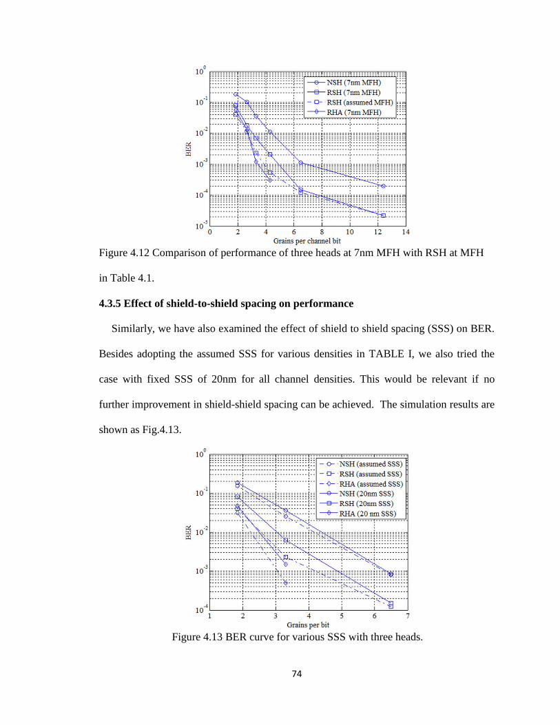
74
Figure 4.12 Comparison of performance of three heads at 7nm MFH with RSH at MFH
in Table 4.1.
4.3.5 Effect of shield-to-shield spacing on performance
Similarly, we have also examined the effect of shield to shield spacing (SSS) on BER.
Besides adopting the assumed SSS for various densities in TABLE I, we also tried the
case with fixed SSS of 20nm for all channel densities. This would be relevant if no
further improvement in shield-shield spacing can be achieved. The simulation results are
shown as Fig.4.13.
Figure 4.13 BER curve for various SSS with three heads.

75
It is found that the performance of the rotated single head (RSH) and the rotated head
array (RHA) still outperform that of a normal single head (NSH) at larger shield to shield
spacing. However, larger shield to shield spacing (SSS) has degraded the performance of
the rotated single head slightly more than that of the normal single head. The reason is
that the RSH relies on narrow SSS to obtain resolution in the crosstrack direction, and the
larger SSS introduces additional ITI which is treated as noise by the RSH, but additional
ISI introduced by the larger SSS for the NSH along the downtrack direction can be
handled with the Viterbi detector. This issue can be addressed with a rotated head array
that forces the additional ITI to zero with information detected from the adjacent tracks
and 2D equalization. It is found that the performance of the RHA with 20nm SSS is quite
close to the RSH with narrow SSS.
4.4 Conclusion
In this chapter, a novel system design for readback above 1 Tbit/in2 density of
conventional media is investigated. Simulation indicates that a rotated head achieves a
density gain of 1.7x (single head) or 2.1x (array) over a normally oriented single head at a
target BER of 10-3
with sampling period of 2nm, minimum mean square error equalizer
and a Viterbi detector. It is found that the new design performs best for low bit aspect
ratio, which differs from the normally oriented head. Head noise is predicted to have only
a minor impact unless an order of magnitude increase is observed relative to accepted
physical models. The rotated head array shows increased advantage over the single
rotated head for larger magnetic fly heights and shield to shield spacing. The rotated head
combined with oversampled signal processing shows great advantage at all densities over
the normally oriented single head with a 1D detector and avoids the implementation of a

76
complex 2D detector and head array. It means established 1D detector schemes can still
be applied to very high density systems with the proposed head design, thus limiting the
change in detection technologies.
77
Chapter 5 Reader design for bit patterned media recording at
10 Tbits/in2 densities
5.1 Introduction
Bit patterned media recording (BPMR) is a promising technology that has been
proposed to extend area density beyond 1 Tbit/in2 because thermal stability is based on
the volume of the whole bit, not individual constituent grains [5.1]. The density can be
greatly increased to 10 Tbits/in2
when shingled writing [5.2, 5.3] is used to record on the
bit patterned media. At such a high recording density, inter-symbol interference (ISI) and
inter-track-interference (ITI) will be a major impairment that seriously degrades the
system performance.
Several detection and equalization methods have been proposed for BPMR. The
modified Viterbi algorithm to mitigate ITI has been studied [5.4]. It is found that joint-
track equalization and detection [5.5] can enhance performance when the ITI is more
severe. Two-dimensional (2D) equalization technology using a 2D equalizer with a one-
dimensional (1D) generalized partial response (GPR) target has been considered in Ref.
[5.6]. Additionally, a 2D GPR target combined with maximum a posterior (MAP)
detector and low-density parity-check (LDPC) has been used to reach 4 Tb/in2
[5.7].
However, little research has been performed to design a reader to effectively combat the
ISI and ITI better than the various existing detection schemes.
In this chapter, a novel reader is proposed for BPMR systems at extremely high
density. This concept is also useful for other very high density media such as the media in
two-dimensional magnetic recording (TDMR) systems. The simulation shows that the
proposed reader has more than a 20 dB gain compared to a normal arranged head array

78
for reading back bit patterned media at 10 Tbit/in2. Additionally, the performance of the
new design is examined for various bit patterns, island jitters, and head noises.
5.2 Reader design
5.2.1 Normal read head array
Use of a shingled writer to write 10 Tbits/in2 bit patterned media has been studied in
reference [5.2, 5.3]. However, read back at such high density for a realistic reader with
satisfactory detection performance has not been reported yet.
The severe ITI and ISI make reading back using a single head without multiple passes
impossible. Thus, we first employed an array of read heads as shown in Fig.5.1 to detect
the bit patterned media at 10 Tbits/in2, where the island size D is 4×4nm, and the center
to center island distance on the down-track direction Bx and the cross-track direction Bz
are both 8nm, respectively. The central head A is used to primarily pick up the
information on the main track, and the side heads primarily read back the adjacent tracks’
information. Here the conventional giant magnetoresistance (GMR) based read head has
a shield to shield spacing (SSS) of 11nm and magnetic fly height (MFH) is 4nm. The free
layer thickness is 4nm. The head width (along the cross track direction) is 18nm, which
facilitates fabrication. However, this means that the head extends over multiple tracks. A
1D Viterbi algorithm (VA) was adopted with a 2D equalizer. For the equalizer design, a
1D target was used here to force ITI to zero and keep the ISI controllable along the down
track direction, thus avoiding the more complex 2D Viterbi algorithm [5.6].
The results of simulation are not satisfactory, as shown in Session IV, and are poor
compared to the lower density results reported in Ref.[5.4, 5.5, 5.6, 5.7]. In order to

79
compare the results with previous papers, the first part of the study assumes the noise is
additive white Gaussian noise (AWGN), and the SNR is defined as follows:
(5.1)
Where VP is the peak value of the readback signal of an isolated land and σ2 is the
variance of the noise. Here, Vp =1.
Figure 5.1 Schematic of head array on the bit patterned media.
After analysis, we found that the ITI becomes much more severe as the density is
increased, especially when the density approaches 10 Tbits/in2. This differs from
previous studies of detection in BPMR systems, where density is around 4Tbits/in2 or
even smaller. This result is also related to the geometry and arrangement of the reader
compared to the island size and island center to center distance in the cross track
direction. Here, the head almost spans three tracks, as the head length is 18nm, which is
close to the length of three islands (20nm) along the cross-track direction. Hence, ITI
correction is limited to 3 poorly resolved input signals, although the down-track ISI can
be corrected quite well with a Viterbi algorithm. This means that addressing the ITI in a
better way needs to be studied; it may be that rearrangement of our system is a possible
solution.
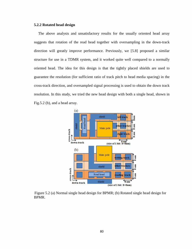
80
5.2.2 Rotated head design
The above analysis and unsatisfactory results for the usually oriented head array
suggests that rotation of the read head together with oversampling in the down-track
direction will greatly improve performance. Previously, we [5.8] proposed a similar
structure for use in a TDMR system, and it worked quite well compared to a normally
oriented head. The idea for this design is that the tightly placed shields are used to
guarantee the resolution (for sufficient ratio of track pitch to head media spacing) in the
cross-track direction, and oversampled signal processing is used to obtain the down track
resolution. In this study, we tried the new head design with both a single head, shown in
Fig.5.2 (b), and a head array.
Figure 5.2 (a) Normal single head design for BPMR; (b) Rotated single head design for
BPMR.

81
In the new design, the dimensions remain the same, i.e, the free layer is still 4nm x
18nm, the SSS is 11nm, the magnetic fly height is 4nm, the recording layer thickness is
14nm and the seed layer thickness between the soft under layer (SUL) and recording
layer is 2nm. Here, exchanged coupled (ECC) media is used. The first part of the paper
assumes all the noises are white noise so as to make the results comparable to other
researchers’ paper: the second part of the paper introduces media jitter and reader noise
based on proven physical models [5.9, 5.10] in order to obtain a more realistic system
performance.
5.3 Detection schemes with various head design
5.3.1 Writing and reading process
In this paper, we assume no writing errors occurred. For reading back, the reciprocity
principle [5.11] is used by convoluting a head potential from a finite difference code
[5.12] with the divergence of media magnetization to obtain the playback signals for the
GMR head.
5.3.2 Detection with various head designs
For the rotated single head design, the ISI is more severe than ITI. Along the down-
track direction, a 1D equalizer and Viterbi detector are used to combat the ISI; in the
cross-track direction, the shields are utilized to combat the ITI. As described in Ref.[5.8],
the 1D MMSE equalizer [5.13] uses a target size of 1×3, namely the length of ISI is 3.
Here the monic constraint (g0=1) is adopted for its optimal target shape. This constraint
can be shown as
g=[1,g1,g2] (5.2)
The constraint can be expressed as eq.(5.3),where c=1 and E=[1,0,0]T.
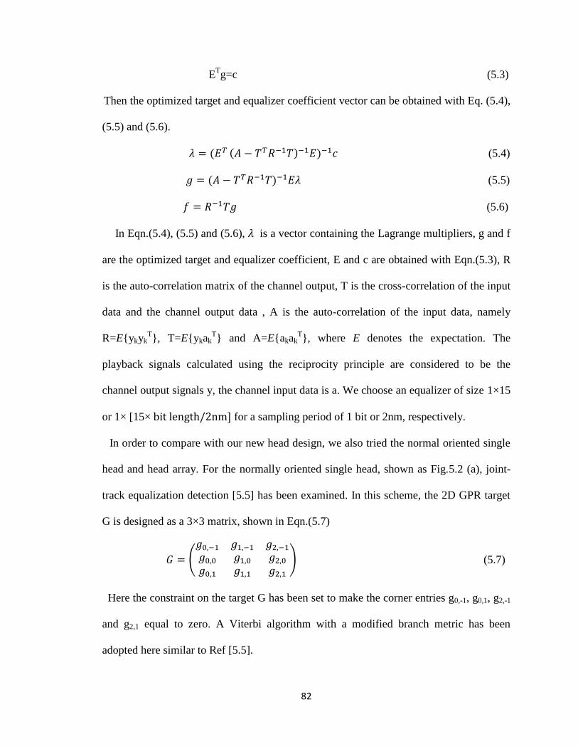
82
ETg=c (5.3)
Then the optimized target and equalizer coefficient vector can be obtained with Eq. (5.4),
(5.5) and (5.6).
(5.4)
(5.5)
(5.6)
In Eqn.(5.4), (5.5) and (5.6), is a vector containing the Lagrange multipliers, g and f
are the optimized target and equalizer coefficient, E and c are obtained with Eqn.(5.3), R
is the auto-correlation matrix of the channel output, T is the cross-correlation of the input
data and the channel output data , A is the auto-correlation of the input data, namely
R=E{ykykT}, T=E{ykak
T} and A=E{akak
T}, where E denotes the expectation. The
playback signals calculated using the reciprocity principle are considered to be the
channel output signals y, the channel input data is a. We choose an equalizer of size 1×15
or 1× [15× for a sampling period of 1 bit or 2nm, respectively.
In order to compare with our new head design, we also tried the normal oriented single
head and head array. For the normally oriented single head, shown as Fig.5.2 (a), joint-
track equalization detection [5.5] has been examined. In this scheme, the 2D GPR target
G is designed as a 3×3 matrix, shown in Eqn.(5.7)
(
) (5.7)
Here the constraint on the target G has been set to make the corner entries g0,-1, g0,1, g2,-1
and g2,1 equal to zero. A Viterbi algorithm with a modified branch metric has been
adopted here similar to Ref [5.5].
83
For the normally oriented head array, shown as Fig.5.1, and the rotated head array, ISI
and ITI can both be addressed using 2-D equalization and detection. By imposing a
constraint on the 2D target that forces ITI to zero and keeps only the controlled ISI, the
conventional VA can handle ISI well. If we make a target of size 3 ×3, namely the length
of ISI and ITI are 3, these constraints are similar to Eq. (15) to (19) in Reference [6].
Then the optimized target and equalizer coefficient vectors can still be obtained with Eq.
(5.5), (5.6) and (5.7). Here we choose a target of size 3×3 for the rotated head array and
an equalizer of size 3×15 or 3×[15× for the rotated head array when the
sampling period is 1 bit or 2nm, respectively. An equalizer of size 7×15 or
7×[15× is chosen for the normally oriented head array in an effort to
make its performance acceptable.
5.4 Numerical evaluation of the new design with white noise
5.4.1 Further study on the read back in TDMR system
First we have performed some further studies on the performance of the rotated single
head in granular TDMR systems based on our previous study [5.8]. In the simulation, a
head similar to the structure shown as Fig.5.2.(b) reads back the media with an average
grain pitch of 5.5nm and bit size of 8nm×6nm. Previously the lost information in the
down-track direction, caused by a large head size compared to the bit size, was recovered
with oversampling. However, increasing the target length is also an option. The readback
performance with larger target length and sampling once per bit is compared with the
case of shorter target length and oversampling in Table 5.1.

84
Target
length
BER(Sampling
2nm)
BER(Sampling
3nm)
BER(Sampling
1 bit)
L=3 4.7% 5.7% 8.4%
L=5 4.5% 5.2% 7.6%
L=7 4.4% 5.0% 7.4%
Table 5.1 BER for various target length and sampling periods in TDMR system.
Table 5.1 indicates that oversampling and increased target length both decrease the
BER, as the former method can discretize the observation with no loss of information and
the latter method equalizes the impulse response of the reader more precisely with longer
target length. It is also found that the performance of the design with oversampling and
L=3 is still better than the case with sampling per bit and longer target length L=7.
Oversampling can lessen the loss of signal, which is a major concern in the extremely
low SNR environment of TDMR system, although the longer target length can provide
better equalized impulse response of the head and decrease the edge effect. Overall,
considering the complexity of the Viterbi algorithm with longer target length and
correspondingly greater detector cost, the method with oversampling and shorter target
length is preferred.
5.4.2 New head design in the BPMR system
For a recording density of 10 Tbits/in2 in a BPMR system, the rotated single head
(RSH), rotated head array (RHA), normal single head (NSH) and normal head array
(NHA) have been utilized with the various equalization technologies described in Session
III. Here the sampling periods of 1 bit and 2nm have been both tried for our new design,
as shown in Fig. 5.3 and Fig. 5.4, respectively.

85
Figure 5.3 BER curves for various head designs with sampling period of one bit.
Fig.5.3 indicates that the rotated single head and rotated head array greatly outperform
the normal oriented single head and normal oriented head array when the sampling period
is one bit. Note that the normal head array cannot reach the target BER of 10-3
for any
reasonable SNR. Reducing the target BER to 10-2
means that the new design offers more
than 15 dB gain compared to the normal head array. The rotated head array performs
slightly better than the single head, providing around 2 dB gain for the target BER of 10-3
,
because the head array can combat the inter-track interference more effectively owing to
the additional information detected by the side heads and the 2D equalization. However,
like any head array, this will probably complicate treatment of head skew.
It is shown in Fig. 5.4 that oversampling can further improve the performance for the
new design. Oversampling provides around 4 to 6 dB gain compared to sampling per bit
for both the rotated single head and the head array. Another interesting observation is that,
if the signal of our new head is oversampled, BER can still reach around 10-3
when the
SNR is as low as 10dB. Such a good performance at low SNR has been seldom found in
previous reports [5.4, 5.5, 5.6, 5.7]. This is caused by two factors as follows. On one hand,

86
the oversampling discretizes the signal with as few losses as possible. On the other hand,
the rotated head picks up much less noise from adjacent tracks compared to the normal
oriented head owing to the arrangement of the shields.
Figure 5.4 BER curves for various heads and sampling periods.
We also compared the performance of the rotated single head with the head array at
various magnetic fly heights (MFH), assuming the sampling period is 1 bit, shown as
Fig.5.5.
The performance discrepancies between rotated single head and head array increase
with increased magnetic fly height, as shown in Fig.5.5, because the pulse width of the
readback waveform in the cross track increases with increasing MFH; correspondingly,
the inter-track interference becomes more severe. The head array can combat ITI more
effectively than the single head with a single pass. The noise floor formed for the rotated
single head with MFH=5nm is dominated by the residual ITI along the cross-track
direction caused by this increased pulse width: it is better addressed by the head array.
Figure 5.5 shows that the performance of the rotated single head and head array are

87
almost the same for 3nm MFH, However, the latter one outperforms the former one when
the MFH approaches 5nm.
Figure 5.5 BER curve for new designs with various MFH.
Compared to the regularly rectangular arrays of islands (Fig. 5.6.a), hexagonal arrays
(Fig.5.6.b) can be formed spontaneously by directed block copolymer self-assembly and
other self-assembly techniques that are considered to be a promising cost-effective
approach to achieving higher density and dimensional uniformity. Hence we also
examined the new head design for the hexagonal islands case, shown as Fig.5.7.

88
Figure 5.6 (a) Rectangular array for 10 Tbits/in2; (b) Hexagonal array for 10 Tbits/in
2.
Figure 5.7 BER curves for Hexagonal array of bits with various sampling periods.
We find that the rotated single head has lower performance when detecting a
hexagonal array of bits than when detecting a rectangular array because the center to
center island distance in the crosstrack is decreased in the former case, and the ITI
becomes more severe.
5.5 Numerical evaluation with more realistic parameters
In this section, we evaluate the performance of our new head design with more
accurate simulation. The dominant contribution to the media noise is the randomness of
island locations, namely jitter, which is nonstationary and data dependent. Reader noise
is known to be flat band-limited noise with SNR dependent on data rate and free layer
volume, according to accepted physical models [5.9, 5.10]. Due to the difference of real
noise and AWGN noise, the jitter noises are simulated with both Taylor expansion and
more accurate techniques, and the head noises are calculated with a physical model. This
will provide more valuable and accurate results compared to the method of section IV
where all noises were treated as additive AWGN noise.
5.5.1 Simulation methods

89
The media jitter in both down track and cross track directions are modeled as two
independent, zero-mean Gaussian random variables and , with variances and
. Then the readback signal obtained by the head centered at (x, z) with an island
centered at (x+ , z+ ) can be expressed in a Taylor series expansion [5.11], shown as
Eq.(5.9).
The jitter induced voltage is shown in Eq.(5.10).
(5.10)
Here is the residual error if the first three orders are included. is the jitter
induced voltage. For the Taylor expansion method, the entire first, second and third order
derivative terms are included when the jitter noise is >5% in order to make the residual
error small.
We have also modeled the island jitter noises with a more realistic model. In this model,
the system is discretized with a 0.1nm grid to simulate the randomness of small bits’
location. The jitters along both down-track and cross-track directions are randomly and
independently generated for each island: the position of each island varies in both
directions. We compare the read back signal for the case without jitter to that with jitter.
This method is very computationally intensive.
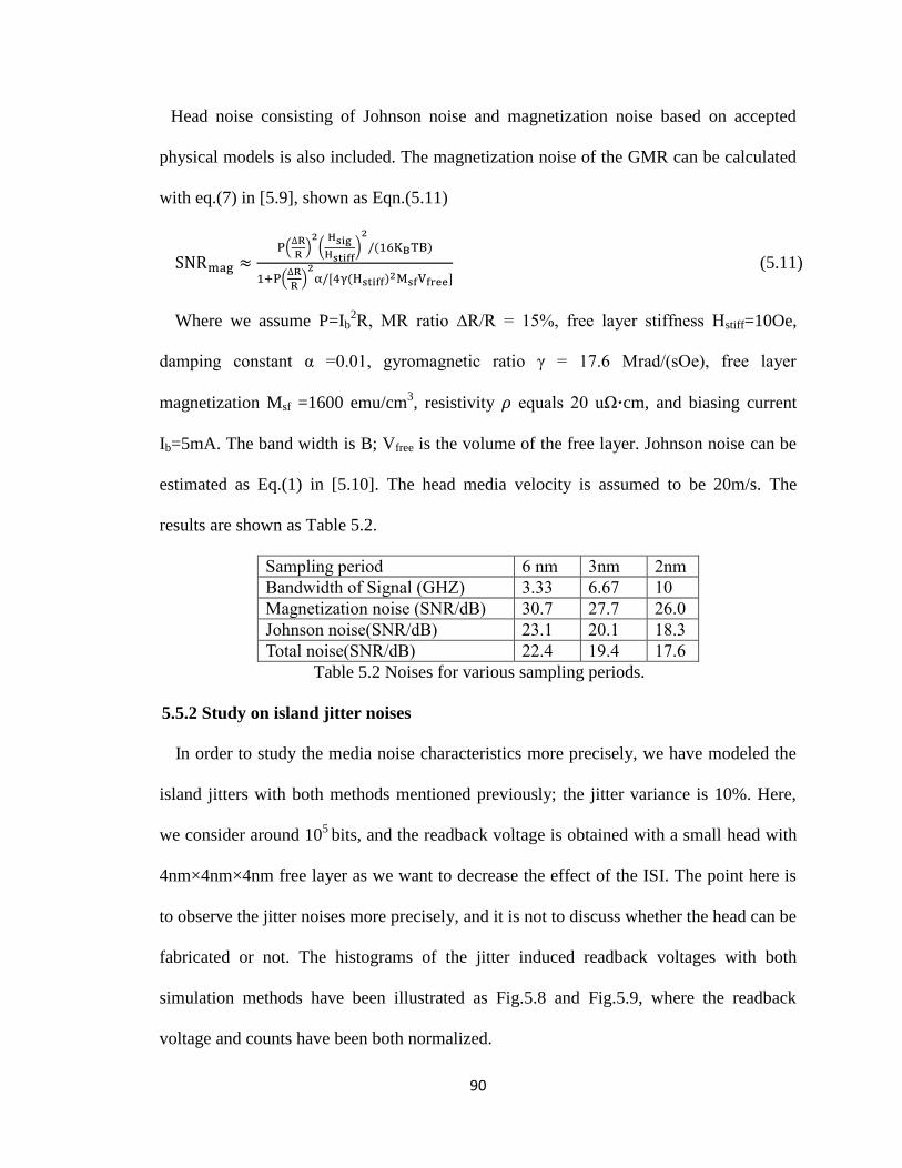
90
Head noise consisting of Johnson noise and magnetization noise based on accepted
physical models is also included. The magnetization noise of the GMR can be calculated
with eq.(7) in [5.9], shown as Eqn.(5.11)
(
) (
)
(
)
(5.11)
Where we assume P=Ib2R, MR ratio ∆R/R = 15%, free layer stiffness Hstiff=10Oe,
damping constant α =0.01, gyromagnetic ratio γ = 17.6 Mrad/(sOe), free layer
magnetization Msf =1600 emu/cm3, resistivity 𝜌 equals 20 uΩ·cm, and biasing current
Ib=5mA. The band width is B; Vfree is the volume of the free layer. Johnson noise can be
estimated as Eq.(1) in [5.10]. The head media velocity is assumed to be 20m/s. The
results are shown as Table 5.2.
Sampling period 6 nm 3nm 2nm
Bandwidth of Signal (GHZ) 3.33 6.67 10
Magnetization noise (SNR/dB) 30.7 27.7 26.0
Johnson noise(SNR/dB) 23.1 20.1 18.3
Total noise(SNR/dB) 22.4 19.4 17.6
Table 5.2 Noises for various sampling periods.
5.5.2 Study on island jitter noises
In order to study the media noise characteristics more precisely, we have modeled the
island jitters with both methods mentioned previously; the jitter variance is 10%. Here,
we consider around 105
bits, and the readback voltage is obtained with a small head with
4nm×4nm×4nm free layer as we want to decrease the effect of the ISI. The point here is
to observe the jitter noises more precisely, and it is not to discuss whether the head can be
fabricated or not. The histograms of the jitter induced readback voltages with both
simulation methods have been illustrated as Fig.5.8 and Fig.5.9, where the readback
voltage and counts have been both normalized.

91
Figure 5.8 Histogram for normalized jitter induced voltage using the Taylor expansion
technique.
Figure 5.9 Histogram for normalized jitter induced voltage using exact signal.
Fig.5.8 and Fig.5.9 show that jitter induced readback voltage follows non-Gaussian
distribution with most of the readback voltages negative. The two methods seem to agree
with each other qualitatively, but the significantly broader histogram of the method using
the exact signal indicates the high order effect of Taylor expansion. This illustrates that
the third order approximation to the island jitter can be inadequate. The positive voltages
are produced by the interference from neighboring bits.

92
We also calculated the jitter –induced readback voltages with more realistic free layer
dimensions of 9nm×9nm×4nm and 18nm×18nm×4nm as shown in Fig.5.10 and Fig.5.11,
respectively.
Figure 5.10 Histogram for normalized jitter induced voltage with 9nm head.
Figure 5.11 Histogram for normalized jitter induced voltage with 18nm head.
Fig.5.10 and Fig.5.11 show that the proportion of positive jitter induced voltage has
increased when the head size is increased. This is due to the increased ISI caused by the
increased head sizes. As the bits are written in a pseudorandom sequence, the
interferences from the neighboring bits will be randomly distributed. Those interferences

93
combined with the jitter noises make jitter-induced readback voltages behave like parts of
Gaussian distribution. However the statistics indicate that the proportion of negative
voltage is still around 2 times larger than the positive ones even when the head is as large
as 18nm.
We also study the performance of the new design (18nm×18nm×4nm free layer) when
media and head noise are present. In this study, the media jitter ranges from 3% to 11%,
the head noise is approximately 23.7 dB and 17.6 dB when the sampling periods are 1 bit
and 2nm, respectively. The results are shown as Fig.5.12, where the linear y axis is
adopted instead of the log y axis.
Figure 5.12 BER VS Media jitter and head noises for various schemes.
The head array can mitigate the jitter along the crosstrack direction better than the
single head, thus producing the improved performance seen in Fig.5.12. Oversampling
mitigates the jitter along the downtrack direction, also producing improved performance.
Consequently, the rotated head array and oversampling provide the best resistance to
severe jitter as shown in Fig.5.12.
5.6 Conclusion

94
In this chapter, a novel system design for readback at 10 Tb/in2density is investigated,
primarily for use in BPMR. The premise of the rotated head design is that ITI is a worse
problem than ISI, because they are treated differently in the channel owing to the
inability to adequately sample in the cross-track direction. The rotated head combined
with oversampled signals, MMSE equalizer, and Viterbi detector can offer more than 20
dB gain over the conventionally oriented head array. Jitter noise is studied and found to
be non-Gaussian. The rotated head array outperforms rotated single head when the MFH
is larger than 3nm. The rotated head array combined with oversampling provides the best
resistance to severe jitter.

95
Chapter 6 Study of Two-dimensional Magnetic Recording
System including Micromagnetic Writer
6.1 Introduction
Two-dimensional magnetic recording (TDMR) has been proposed as a promising
approach for ultra-high densities towards 10 Tbits/in2
[6.1]. Shingled writing, which
makes extensive use of track overlap, can be used for writing data in TDMR. During each
pass, the head writes a wide (multiple tracks) signal, but then trims the signal to a single
track width with the next pass. Readback can be implemented with various detection
schemes, such as an inversion detector, 2D MAP detectors, etc. [6.2]. Previously, various
writing and reading models have been proposed for TDMR systems. K.S.Chan [6.2] has
proposed the grain-flipping probability model to study the performance of various
detectors in TDMR with 6nm grain size. Reference [6.3] used a simplified writing
process to study the TDMR specifications and compare various equalizer designs for
4.6nm grains.
However, few studies have been done for the design and optimization of the whole
writer, reader and detector using a more accurate micromagnetic model to write realistic
8nm Voronoi grains. Previously, we proposed a rotated reader design for readback at
ultra-high density from granular media [6.4] with perfect writing; the user density was
greatly increased to 10.1 Tbits/in2
with the new design. In this study, realistic writing with
both conventional and optimized writers and reading with various readers have been
studied using a micromagnetic model. First, a micromagnetic conventional writer was
utilized to write data on exchanged coupled composite (ECC) media at 2 Tbits/in2
channel bit density. Readback was implemented with both a single rotated sense head

96
(RSH) and a normally oriented single head (NSH) with sampling period of 2nm,
minimum mean squared error equalizer and Viterbi detectors. Additionally the effect of
skew was investigated. Also, an optimized shingled writer has been proposed to reach
higher user density that approach the predicted maximum user areal density (4.66
Tbits/in2) [6.5] for 8nm grains size with ideal writer and perfect reader resolution.
6.2 Shingled recording-conventional writer
6.2.1 Conventional writer design
First, a conventional writer consisting of a main pole and a trailing shield has been
employed to study the achievable user density with shingled writing, shown in Fig.6.1.
The dimension of the main pole and the trailing shield were 40 nm×60 nm and 80nm ×
120nm in the cross-track and down-track directions, respectively. The trailing shield to
main pole spacing was 40nm. The pole tip in the write head model was simulated
micromagnetically. The main pole had an anisotropy field of 10 Oe oriented in the cross-
track direction and saturation magnetization of 1910 emu/cm3. The saturation
magnetization of the trailing shield was 480 emu/cm3. The magnetic fly height between
recording media surface and air-bearing surface was considered to be 7nm. Simulation
indicated the writer could generate a maximum perpendicular field of 11500 Oe with
maximum gradients of 320 Oe/nm at the trailing edge.

97
Figure 6.1 Down-track view of the conventional writer.
6.2.2 ECC media design
An ECC media structure was used for the micromagnetic simulations with soft under
layer (SUL) replaced by an ideal imaging scheme assuming an infinite SUL with a
permeability of 100. The recording layer was ferromagnetic ECC media with a top
relatively soft layer and a bottom hard layer, whose thicknesses were both 6.5nm. The
seed layer between recording layer and SUL was 4nm thick. Voronoi grain with average
diameter of 8nm, non-magnetic grain boundaries of 1nm and a standard deviation of 20%
were used in the simulation. The easy axis dispersion of the grains followed a Gaussian
distribution with a standard deviation of 2°. The bottom layer had anisotropy field
Hk=19.5 kOe and Ms=600 emu/cm3. The top layer had Hk=6.5KOe and Ms=600 emu/cm
3.
The intergranular exchange constant Jex was 0.3 and the interlayer exchange coupling,
Jex/V was 9 × 10⁶ erg/cm
3, where V was the volume of the grain [6.6].
Also we have employed an optimized ECC media with the same switching field, but
thinner thickness of 10nm. The object was to maximize the ratio of the stabilizing energy
barrier to the switching field Hs, , where Ms was the saturation
magnetization and V was the volume of the grain. The thicknesses of the top soft layer
and bottom hard layer were 6.7nm and 3.3nm, respectively. The bottom layer was the
hard layer with Hk=167 KOe and Ms=150 emu/cm3. The top layer had Hk=64 Oe and
Ms=750 emu/cm3. Jex remained 0.3 and the interlayer exchange coupling, Jex/V became
5.76 × 10⁶ erg/cm
3 [6.6].
6.2.3 Reader design and detection scheme

98
Previously, a rotated reader design combined with oversampling signal processing was
proposed for readback at ultra-high density from both granular media [6.4] and bit
patterned media [6.7] with perfect writing. A schematic drawing of a rotated head array
(RHA) is shown in Fig.6.2, where head labeled “A” detected the data in the current main
track, while side heads labeled “B” and “C” were used to detect the adjacent tracks. The
distance between the centers of central head and side heads was varied to obtain the
lowest bit error rates. Here a conventional giant magnetoresistance (GMR)-based head
was used, and the dimension of the free layer was 28nm × 28nm ×5nm, shield to shield
spacing was 19nm and magnetic fly height was 7nm. For read back, the physically
accurate reciprocity principle was used by convolving a head potential [6.5] with the
divergence of media magnetization to obtain the playback signals.
Figure 6.2 Schematic of rotated head array design.
The playback signals calculated with the reciprocity principle were considered as
channel output signals, which were processed with a moving average filter before the
equalization. For both rotated and normally oriented single head, the 1D MMSE
equalizers was adopted, whose size was 1× [15 × bit length/2nm] for a sampling period
of 2nm. The size of the 1-D target was 1×3 bits, and the monic constraint was used whose
first coefficient was 1. For a rotated singled head with multiple scans and a head array, a
2-D MMSE equalizer of size 3× [15 × bit length/2nm] was used when the sampling

99
period was 2nm. Here, during the design of the 2-D general partial response (GPR)
equalizer, a 1-D target with size of 1×3 bits (using the monic constraint) was used instead
of a 2-D target; this design reached the same performance as the 2-D GPR equalizer with
a 2-D zero forcing ITI target, but with a decreased computational complexity [6.8]. It’s
important to note that the multi-track output was still used to 2-D equalize the main track
into an ITI free and controllable ISI 1-D target, hence there was no residual ITI. After
both 1- and-2-D equalizers, a conventional Viterbi detector was implemented.
6.2.4 Simulation results for the conventional shingled writer
A conventional writer was utilized to write a pseudo-random binary sequence on ECC
media. Both rotated and normally oriented readers were utilized. The reader noise was
taken to be flat-band-limited noise with SNR dependent on the data rate and free layer
volume, according to accepted physical models [6.9], [6.10]. The head noise consisted of
both magnetization noise and Johnson noise. The reader SNR for sampling per 2nm was
about 24 dB relative to a long wavelength signal. During the simulation, the BAR was
varied during the writing process to obtain the optimum performance for each system.
Then the corresponding user areal density (Fig. 6.3) can be calculated with the Shannon
Capacity limit [6.11] according to the bit error rates obtained in the simulation.

100
Figure 6.3 User Areal Density for various heads and media thicknesses.
Simulation indicated that user areal densities of 1.19Tbits/inch2
and 0.68Tbits/inch2
could be obtained by the RSH and the NSH with sampling period of 2nm for 13nm ECC
media: this performance was not very satisfying due to the un-optimized writer and
media design. It was also found that the optimum BAR for NSH was about 2.25, while
the RSH performed better for lower BAR (<1) case. The reason for this was that varying
BAR meant varying the amount of interference introduced by the reader in both down
and cross track directions. For the normally oriented single head, avoiding the detriment
of inter track interference (ITI) was a major concern; hence a higher BAR was wanted. In
contrast, the rotated single head addressed the inter symbol interference (ISI) and ITI
equally effectively; correspondingly a lower BAR approaching 1 became preferable. If
optimized 10nm media was utilized in the simulation, user densities of 1.52Tbits/in2 and
1.09Tbits/in2 could be achieved with the RSH and the NSH due to the larger writing field
and gradient allowed by the reduced media thickness, while the optimum BARs for both
readers remained the same as those of the 13nm media case.
6.2.5 Effect of skew

101
The effect of skew is detrimental to the performance of shingled writing because it
widens the erase band and broadens transitions. In this study, we compared the
performances of rotated single head and normally oriented head for both the no skew and
skewed cases for the 10nm medium, shown as Fig.6.4. It indicated that the skew angle
(15°) degraded both the RSH and the NSH due to additional ISI and ITI introduced by
the skew, The RSH with multiple scans (with the reader always centered over its track)
could provide better resistance to the effect of skew angle because the additional
information about adjacent tracks detected by multiple scans and 2-D equalization meant
that the system could tolerate the additional ITI and ISI brought by the skewed reader
more robustly.
Figure 6.4 The BER for various heads with both skewed and no skew cases for the 10nm
medium.
6.3 Optimized writer design
6.3.1 Specification of optimized writer
It is obvious that the conventional writer design above is not optimum for shingled
writing due to the low head field gradient and lack of side shield, which will cause poor

102
transitions, and even severe erasure for adjacent tracks and bits. Correspondingly an
optimized writer is needed to achieve higher user areal density. We proposed a shingled
recording head, shown in Fig.6.4. Considering that the corner of the head was utilized to
write data for shingled writing, maximizing the gradients at the writing corner and
avoiding adjacent track erasure was the key to optimization. Fig.6.5 (a) is the down-track
view of the proposed writer, and Fig.6.5 (b) illustrates the writer structure with a top
down view. Our writer consisted of a main pole, side shield, a trailing shield, and a soft
underlayer assumed to offer perfect imaging. A saturation flux of 2.4 Tesla was applied
uniformly at the top surface of the main pole. The flux was completed by applying an
equal but negative flux on the top surfaces of trailing and side pole. Both the bases of the
main pole and return pole had widths of 20nm and shield to head spacing was assumed to
be 10nm. It was found that a larger main pole (40nm) will cause more adjacent track
erasure (ATE), while a smaller one (10nm) cannot provide large enough field. Both the
trailing and side shields were utilized to control the field on both down and cross track
direction. The slopes of the shield and main pole were optimized to be 45° and 30° to
maximize the amount of flux into the writing pole tip and shield pole tip, thus
maximizing the writing field and minimizing ATE.
In the optimized design, the saturation magnetization of the parts labeled in 1 and 2 in
Fig.6.5 (a) were 2000 and 200 emu/cm3, respectively. The low Ms (200 emu/cm
3) of
both shields allows for efficient removal of flux from previously written bits and tracks
without producing an ATE field. Simulation indicated that the field under the shield
stayed below 1kOe, which was far smaller than the expected recording layer switching
field (7000Oe). The parts of the head below the white dotted line in Fig.6.5 (a) had larger

103
anisotropies than the parts above the dotted line, which provided improved field strength
and field gradients at the corner of the writing pole. The value of uniaxial anisotropy field
(Hk) for parts below the dotted line labeled 1 and 2 were 4000 Oe and 2000 Oe,
respectively. Above the dotted line, the anisotropies of the main pole and shields were
much smaller, 10 Oe and 400 Oe, respectively.
6.3.2 Field profile
The recording field produced by the proposed writer could be obtained with
micromagnetic simulation as Fig.6.6, where the field was evaluated 6nm below the air
bearing surface. The maximum field of about 10 kOe was produced at the corner of the
main pole, while the fields under the shield were below 1 kOe. The perpendicular writing
field gradient of about 800 Oe/nm in both down track and cross track directions occurred
at write fields of about 7 kOe, as shown in Fig.6.7. Correspondingly the switching field
of the optimized 10nm ECC media was set to be 7 kOe. A sample magnetization pattern
of random sequence was shingle written on the granular medium at about 4.5 Tbits/in2
channel bit density, shown as Fig.6.8, where bits with the bit length of 12nm and the
track pitch of 12nm were written.

104
Figure 6.5 Optimized shingled recording head (a) the down-track view; (b) the air bearing
surface view.
Figure 6.6 Shingled head perpendicular field profiles resulting from micromagnetic
simulations.

105
Figure 6.7 Perpendicular field gradients along both down and cross track directions.
Figure 6.8 (a) Random magnetization pattern to be written on the granular medium. (b)
The final written pattern using the proposed optimized writer.
6.3.3 Densities reached by the designed head
The proposed optimized writer was used to write a pseudo-random-bit sequence (PRBS)
on the optimized 10nm ECC media. Both rotated single head and head array were utilized
for readback. The dimension of the free layer was 18nm ×18nm ×4nm, and shield to
shield spacing was 11nm. The reader SNR for sampling per 2nm was about 18 dB. In the
simulation, the number of grains per bit and BARs were both varied during the writing
process in order to obtain optimal results.
The possible capacities achieved by both readers were shown in Fig.6.8. It was found
that our proposed system could obtain better results at lower bit-aspect ratio (≤1), which

106
was different from the usual high bit aspect ratio(≥2) adopted in the other reports [6.2],
[6.3]. The reason for this was the field and field gradient produced by the proposed writer
were symmetric in both down and cross track directions, which meant the writing
performance was approximately the same along both directions. Besides the rotated
reader design worked best for low BAR, especially for the RHA with the enhanced
treatment of ITI [6.12]. Fig.6.9 indicated that the maximum user areal density achieved
by the RSH and the RHA was about 3.60 Tbits/in2
(with a track pitch of 12nm) and 4.03
Tbits/in2
(with a track pitch of 10nm) for 2.88 grains/channel bits, respectively. For 2
grains/channel bits, the maximum user areal density achieved by the RSH and the RHA
was about 3.76 Tbits/in2 (with a track pitch of 7nm) and 4.52 Tbits/in
2 (with a track pitch
of 7nm), which was close to the predicted maximum user areal density (4.66 Tbits/in2)
for 8nm grains with ideal writer and perfect reader resolution combined with a threshold
detector [6.5]. For the RHA, optimization indicated that side heads should be moved
closer to the main head instead of being at the center of adjacent tracks to obtain the
lowest BER, and the optimum offset for side heads was about 2nm away from the center
of adjacent tracks. We also observed that the RHA showed performance improvement
compared to the RSH. Especially large improvements were found for few grains per bit
because the information detected on the adjacent track and the 2-D equalization adopted
by the RHA could better combat the severe ITI and ATE brought by the larger reader size
and imperfect writer gradient when the bit size was decreased. The simulation also
indicated that if the proposed writer was used to write a PRBS on granular media with
6nm grains, the BER was about 2% for a channel bit density of 6.7 Tbits/in2;
correspondingly, a user areal density of 5.8Tbits/in2 could be reached.

107
Fig.6.9 User Areal Density for the RSH and the RHA at 2.88 and 2 grains/channel bits
for the optimized writer.
6.4 Conclusion
In this chapter, the performances of rotated and normally oriented single head were
investigated when a conventional writer was used to shingle write data in a TDMR
system. Simulation indicated that the user densities of 1.52Tbits/in2 and 1.09Tbits/in
2
could be achieved with a rotated single read head and a normally oriented single read
head with sampling period of 2nm, minimum mean squared error equalizer and Viterbi
detectors, respectively. It was also found that the RSH with multiple scans and 2D
equalization provided better resistance to skew. All user areal densities were calculated
with the Shannon Capacity limit [11] by assuming a very long code word and treating the
recording channel as a binary symmetric channel. With an optimized writer, for 2
grains/channel bits, the maximum user areal density achieved by the RSH and the RHA
were about 3.76 Tbits/in2 and 4.52 Tbits/in
2, which was close to the predicted maximum
user areal density (4.66 Tbits/in2) for 8nm grains with ideal writer and reader.
108
Summary
In this thesis, a novel reader design is proposed to readback user areal densities from 1-
10 Tbits/in2 recorded on granular media. The reader is also extended to readback bit
patterned media with 10 Tbits/in2 densities. A shingled micromagnetic writer is proposed
and combined with the new reader design to reach user areal density above 4 Tbits/in2
and near 6 Tbits/in2 for 8nm and 6nm Voronoi grains, respectively.
Readback at ultra-high density from a granular media with a realistic reader, such as
that envisioned for two-dimensional magnetic recording, is quite challenging due to the
increased inter-track interference, inter-symbol interference, increasing writing errors and
an extremely low signal-to-noise ratio (SNR) environment. The key idea of the novel
reader design is a rotated sense head, so that the shields are aligned downtrack, combined
with oversampled signal processing to regain the lost down-track resolution. Based on a
random Voronoi grain model, simulation indicates that for near squared bits with 5.5 nm
grains, and a rotated single reader, the bit error rate can drop from 20.9% for a normally
positioned head array to 4.2% for a single-rotated single head with sampling period of 2
nm, a minimum mean squared error equalizer, and pattern-dependent noise prediction
detector. The user density computed using the Shannon capacity limit is greatly increased
to 10.1 Tb/in2.
The reason for the superior performance of this reader is analyzed. The study indicates
that the significant improvement in performance in the rotated head compared to the
normally oriented head can be attributed to the larger amplitude of its dibit response and
the reduced overlap between conditional probability density functions. An LDPC code is
introduced for the system design with different bit aspect ratios. Simulation indicates that

109
maximum areal densities of 9.85T/in2 and 6.64T/in
2 can be reached by the rotated head
array (RHA) and normally oriented head array (NHA) at optimum bit aspect ratios of
0.67 and 3.5 for 5.5nm Voronoi grains, respectively. After decoding, the performance of
the NHA is about 8.5dB worse than the RHA. With an oversampled signal, 2D linear
minimum mean-squared error (LMMSE) equalizer and LDPC codes, a user bit density
near 10 Tbits/in2 is feasible for a rotated head array.
The performance of a rotated sense head is examined for densities of 2–7 Tbits/in2
recorded on granular media, such as that envisioned for 2-D magnetic recording.
Simulation shows that the new design achieves a density gain of 1.7X (single head) and
2.1X (head array) over a normally oriented single head at a target bit error rate (BER) of
10−3
with sampling period of 2 nm, minimum mean square error equalizer, and Viterbi
detector. The new design shows greatly reduced BER relative to a normally oriented
single head for all densities, including a very few grains per channel bit (<2).
If such a reader design is implemented for readback of bit patterned media at 10
Tbits/in2. Simulation results show that the proposed reader has more than 20 dB gain
compared with a normally oriented head array for reading back at 10 Tbits/in2 for
rectangular bits. We also examined the tradeoff between oversampling and increased
target length. Island jitters are proved to be non-Gaussian distributed. The performance
of the new design is investigated for both rectangular and hexangular bits combined with
realistic island jitters.
A shingled micromagnetic writer is proposed for a TDMR system and readback with
various readers. First, the performance of rotated and normally oriented single heads was
investigated when a conventional writer was used to shingle write data in a TDMR

110
system. Simulation indicated that the user densities of 1.52Tbits/in2 and 1.09Tbits/in
2
could be achieved with a rotated single read head and a normally oriented single read
head with sampling period of 2nm, minimum mean squared error equalizer and Viterbi
detectors, respectively. It was also found that the RSH with multiple scans and 2D
equalization provided better resistance to skew. With an optimized writer, for 2
grains/channel bits, the maximum user areal densities achieved by the RSH and the RHA
were about 3.76 Tbits/in2 and 4.52 Tbits/in
2, which was close to the predicted maximum
user areal density (4.66 Tbits/in2) for 8nm grains with ideal writer and reader.

111
Reference
[1.1] Source: http://rondennison.com/services.htm.
[1.2] IBM 350 disk storage unit. [Online].Available: http://www.03.ibm.com/ibm
/history/exhibits /storage/storage_350.html.
[1.3] H. J. Richter, "Recent advances in the recording physics of thin-film media,"
Journal of Physics D - Applied Physics, vol. 32, pp. R147-R168, Nov 7 1999.
[1.4] H. J. Richter, "The transition from longitudinal to perpendicular recording,"
Journal of Physics D - Applied Physics, vol. 40, pp. R149-R177, May 7 2007.
[1.5] H, J. Richter, A.Y. Dobin, O. Heinonen et al., “Recording on Bit-patterned media
at densities of 1 Tb/in2 and beyond”, IEEE Trans. Magn., vol.42,no.10, pp.2255-
2260, Oct. 2006.
[1.6] Jian-Gang Zhu, X. Zhu and Y. Tang, “Microwave assisted magnetic recording”,
IEEE Trans. Magn., vol.44, no.1, pp.125-131, Jan. 2008.
[1.7] Roger Wood, “The feasibility of magnetic recording at 1 Terabit per square inch”,
IEEE Trans. Magn., vol.36, no.1, pp.36-42, Jan.2000.
[1.8] M. H. Kryder and R. W. Gustafson, “High-density perpendicular recording-
advances, issues and extensibility,” J. Magn. Magn. Mat., vol. 287, pp. 449-458,
Feb. 2005.
[1.9] M. H. Kryder, E. C. Gage, T. W. McDaniel, W. A. Challener, R. E. Rottmayer, G.
Ju,Y.-T. Hsia, and M. F. Erden, “Heat assisted magnetic recording,” Proceedings
of the IEEE, vol. 96, no. 11, pp. 1810-1835, Nov. 2008.
[1.10] M. A. Seigler, W. A. Challener, E. Gage et al., “Integrated head assisted magnetic
recording head: design and recording demonstration”, IEEE Trans. Magn., vol.44,
no.1, 119-124, Jan. 2008.
[1.11] S. Greaves, Y. Kanai, H. Muraoka, “Shingled recording for 2-3 Tbit/in2”, IEEE
Trans. Magn., vol.45, no.10, pp.3823-3829, Oct. 2009.
[1.12] Source:http://www.seagate.com/about/newsroom/press-releases/terabit-milestone-
storage-seagate-master-pr/.
[1.13] Y. Shiroishi, K. Fukuda, I. Tagawa, H. Iwasaki, S. Takenoiri, H. Tanaka, H.
Mutoh, and N. Yoshikawa, “Future options for HDD storage,” IEEE Trans.
Magn., vol. 45, no. 10, pp. 3816–3822, Oct.2009.
[1.14] Source : http://forensic-proof.com/archives/3160.
[1.15] Source:http://lookup.computerlanguage.com/host_app/search?cid=C999999&term
= longitudinal+ recording&lookup.x=13&lookup.y=6.
[1.16] Source:http://lookup.computerlanguage.com/host_app/search?cid=C999999&term
=perpendicular+recording&lookup=Go
[1.17] Felipe Garcia Sànchez and D. Weller. Magnetic recording crisis and challenges.
N.d. Graphic. Thesis Web. 14 Nov. 2011.
[1.18] D. Z. Bai and J. G. Zhu, "Micromagnetics of perpendicular write heads with
extremely small pole tip dimensions," Journal of Applied Physics, vol. 91, pp.
6833-6835, May 15 2002.
[1.19] Wood, R. ,“Shingled Magnetic Recording and Two-Dimensional Magnetic
Recording,” IEEE Magnetics Society Meeting, Santa Clara, CA, Oct. 19 2010.
[1.20] R.H.Victora and X.Shen, “Composite media for perpendicular magnetic
recording” IEEE Trans. Magn., vol. 41, no. 2, pp. 537–542, Feb.2005.
112
[1.21] D. Suess, “Multilayer exchange spring media for magnetic recording,”Appl. Phys.
Lett., vol. 89, p. 113105, 2006.
[1.22] M. N. Baibich, J. M. Broto, A. Fert et al., “Giant magnetoresistance of (001)
Fe/(001) Cr magnetic superlattices”, Phys. Rev. Lett. vol.61, pp. 2472-2475, 1988.
[1.23] Binasch, G., Grunberg, P., Saurenbach, F. & Zinn, W. “Enhanced
magnetoresistance in layered magnetic structures with antiferromagnetic
interlayer exchange”, Phys. Rev. B, vol. 39, pp.4828–4830, Mar.1989.
[1.24] S. M. Thompson, “The discovery, development and future of GMR: The Nobel
prize 2007,” J. Phys. D, vol. 41, pp. 093001-1–093001-20, Mar. 2008.
[1.25] M. Takagishi et al., “The applicability of CPP-GMR heads for magnetic
recording,” IEEE Trans. Magn., vol. 38, no.5, pp. 2277-2282, Sep.2002.
[1.26] Childress J R and Fontana R E Jr, “Magnetic recording read head sensor
technology,” Computers rendus Physique vol. 6, issue 9, pp. 997-1012, 2005.
[1.27] H. Yuasa, M. Yoshikawa, Y. Kamiguchi, K. Koi, H. Iwasaki, M. Takagishi, and
M. Sahashi, “Output enhancement of spin-valve giant magnetoresistance in
current-perpendicular-to-plane geometry,” J.Appl. Phys., vol. 92, p. 2646, 2002.
[1.28] M. Saito et al., “Narrow track width CPP spin-valve GMR heads utilizing half-
metallicity materials,” presented at the Intermag 2005 Conf., Nagoya, Japan,
Paper FB-02.
[1.29] H. Oshima, K. Nagasaka, Y. Seyama, A. Jogo, Y. Shimizu, A. Tanaka, “Current-
perpendicular spin valves with partially oxidized magnetic layers for ultrahigh-
density magnetic recording,” IEEE Trans. Magn., vol.39, no.5, pp.2377-
2380,Sep.2003.
[1.30] S. Yuasa and D. D. Djayaprawira, “Giant tunnel magnetoresistance in magnetic
tunnel junctions with a crystalline MgO (001) barrier,” J.Phys. D., vol. 40, no. 21,
pp. R337–R354, Nov. 2007.
[1.31] J. Mallinson, “On extremely high density magnetic recording,” IEEE Trans. Magn,
vol.10, no.2, pp.368-373, Jun. 1974.
[1.32] S. H. Charap, P. L. Lu, and Y. J. He, "Thermal stability of recorded information at
high densities," IEEE Trans. Magn, vol. 33, no.1, pp. 978-983, Jan. 1997.
[1.33] Y. Dong and R. H. Victora, “Micromagnetic specification for bit patterned
recording at 4 Tbit/in ,” IEEE Trans. Magn., vol. 47, no. 10,pp. 2652–2655, Oct.
2011.
[1.34] M. A. Siegler et al., “Integrated head assisted magnetic recording head: design
and recording demonstration”, IEEE Trans. Magn., vol.44, no.1, pp.119-124, Jan.
2008.
[1.35] K. S. Chan, R. Radhakrishnan, K. Eason, R. M. Elidrissi1, J. Miles,B. Vasic, and
A. R. Krishnan, “Channel models and detectors for two dimensional magnetic
recording (TDMR),” IEEE Trans. Magn., vol.46, no. 3, pp.804-811, Mar. 2010.
[1.36] A.R.Krishman, R.Radhakrishnan, B.Vasic. eta., “2-D Magnetic recording: read
channel modeling and detection”, IEEE Trans. Magn. vol.45, no.10, pp.3830-
3836, Oct.2009.
[1.37] Hwang E, Negi R, Kumar B V K V (2010),“Signal processing for near 10 Tbit/in2
density in two-dimensional magnetic recording (TDMR),” IEEE Trans. Magn.,
vol. 46, no. 6, pp. 1813–1816, Jun.2010.
113
[1.38] A. Fahrner, “On signal processing and coding for digital magnetic recording
system,” Ph.D. dissertation, Department of Telecommunications and Applied
Information Theory, University of Ulm, Germany, 2004.
[1.39] S. Aviran, “Constrained coding and signal processing for data storage system,”
Ph.D. dissertation, Department of Electrical and Computer Engineering,
University of California, San Diego, 2006.
[1.40] P. H. Siegel, “Recording codes for digital magnetic storage,” IEEE Trans. Magn.,
vo.21, no.5, pp. 1344–1349, Sept. 1985.
[1.41] J. G. Proakis, “Partial response equalization with application to high density
magnetic recording channels,” in CRC Handbook for Coding and Signal
Processing for Recording Systems, B. Vasic and E. M. Kurtas, Eds. CRC Press,
2004.
[1.42] K. A. S. Immink, P. H. Siegel, and J. K. Wolf, “Codes for digital recorders,” IEEE
Trans. Inf. Theory, vol. 44, no. 6, pp. 2260 – 2299, Oct. 1998.
[1.43] J. Moon and W. Zeng, “Equalization for maximum likelihood detectors,” IEEE
Trans. Magn., vol. 31, no. 2, pp. 1083-1088, Mar. 1995.
[1.44] P. Kovintavewat, I. Ozgunes, E. Kurtas, J. R. Barry, and S. W. McLaughlin,
“Generalized partial-response targets for perpendicular recording with jitter noise,”
IEEE Trans.Magn., vol. 38, no. 5, pp. 2340-2342, Sep. 2002.
[1.45] J. Coker, E. Eleftheriou, R. Galbraith, and W. Hirt, “Noise-predictive maximum
likelihood (NPML) detection,” IEEE Trans. Magn., vol. 34, no. 1, pp. 110–117,
Jan 1998.
[1.46] S. Karakulak, P. H. Siegel, J. K.Wolf, and H. N. Bertram, “A new read channel
model for patterned media storage,” IEEE Trans. Magn., vol.44, no. 1, pp. 193–
197, Jan. 2008.
[1.47] S. Nabavi, B. V. K. V. Kumar, and J.-G. Zhu, “Modifying Viterbi algorithm to
mitigate inter-track interference in bit-patterned media,” IEEE Trans. Magn., vol.
43, no. 6, pp. 2274–2276, Jun. 2007.
[1.48] S.Karakulak, P. H. Siegel, andH.N. Bertram, “Joint-track equalization and
detection for bit patterned media recording,” IEEE Trans. Magn., vol. 46, no. 10,
pp. 3639–3647, Oct. 2006.
[1.49] S. Nabavi and B. V. K. V. Kumar, “Two-dimensional generalized partial response
equalizer for bit-patterned media,” in Proc. IEEE Int. Conf. Commun., Glasgow,
U.K., pp. 6249–6254, 2007.
[1.50] M. Keskinoz, “Two-dimensional equalization/detection for patterned media
storage,” IEEE Trans. Magn., vol. 44, no. 4, pp. 533–539, Apr. 2008.
[1.51] W. Chang and J. R. Cruz, “Inter-track interference mitigation for bit-patterned
media recording,” IEEE Trans. Magn., vol. 46, no. 11, pp. 3899-3908, Nov. 2010.
[1.52] Upamanyu Madhow, Fundamentals of digital communication. Cambridge,
U.K.:Cambridge Univ. Press, 2008, pp. 311-324.
[1.53] Caroselli J, Altekar S A, McEwen P, Wolf J K (1997), “Improved detection for
magnetic recording systems with media noise,” IEEE Trans. Magn., vol. 33, no. 5,
pp. 2779–2781, Sep.1997.
[1.54] A. Kavcic and J. M. F. Moura, “The Viterbi algorithm and Markov noise
memory,”IEEE Trans. Inf. Theory, vol. 46, no. 1, pp. 291-301, Jan. 2000.
114
[1.55] J. Moon and J. Park, “Pattern-dependent noise prediction in signal-dependent
noise,”IEEE J. Sel. Areas Commun., vol. 19, no. 4, pp. 730-743, Apr. 2001.
[1.56] Z. Wu, P. H. Siegel, J. K. Wolf, and H. N. Bertram, “Mean-adjusted pattern-
dependent noise prediction for perpendicular recording channels with nonlinear
transition shift,” IEEE Trans. Magn., vol. 44, no. 11, pp. 3761-3764, Nov. 2008.
[1.57] W. Tan and J. R. Cruz, “Signal processing for perpendicular recording channels
with intertrack interference,” IEEE Trans. Magn., vol. 41, no. 2, pp. 730–735, Feb.
2005.
[1.58] K. S. Chan, R. Radhakrishnan, K. Eason, R. M. Elidrissi1, J. Miles,B. Vasic, and
A. R. Krishnan, “Channel models and detectors for two dimensional magnetic
recording (TDMR),” IEEE Trans. Magn., vol.46, no. 3, pp.804-811, Mar. 2010.
[1.59] Y.Wu, J. A. O’Sullivan, N. Singla, and R. S. Indeck, “Iterative detection and
decoding for separable two-dimensional intersymbol intereference,” IEEE Trans.
Magn., vol. 39, no. 4, pp.2115-2120, Jul. 2003.
[1.60] R. W. D. Palmer, P. Ziperovich and T. Howell, “Identification of nonlinear write
effects using pseudorandom sequences,” IEEE Trans. Magn., vol. 23, no.5, pp.
2377–2379, Sept. 1987.
[1.61] Y.Tang and C. Tsang, “A technique for measuring nonlinear bit shift,” IEEE
Trans. on Magn., vol. 27, no.6, pp. 5316–5318, Nov. 1991.
[1.62] F.Lim and A. Kavcic, “Optimal precompensation for partial erasure and nonlinear
transition shift in magnetic recording using dynamic programming,” in Proc.
IEEE Global Telecommun. Conf., Globecom’05, vol. 1, St. Louis, Missouri, USA,
Nov. 28–Dec. 2, 2005, pp. 58–62.
[1.63] Z. Wu, H. N. Bertram, P. H. Siegel, and J. K. Wolf, “Nonlinear transition shift
and write precompensation in perpendicular magnetic recording,” in Proc. IEEE
Int. Conf. Commun. ICC’08, Beijing, China, May 19–23, 2008, pp. 1972–1976.
[2.1] W. F. Brown, Micromagnetics. John Wiley Sons, Inc.1963.
[2.2] E. Della Tore, “Magnetization Calculation of fine of fine particles”, IEEE Trans.
Magn., vol.22, no.5, pp.484-489, Sep.1986.
[2.3] R. H. Victora, J. Xue, and M. Patwari, “Areal density limits for perpendicular
magnetic recording,” IEEE. Trans. Magn., vol. 38, no. 5, pp.1886–1891, Sep.
2002.
[2.4] M. E. Schabes and A. Aharoni, “Magnetostatic interaction fields for three
dimensional array of ferromagnetic cubes”, IEEE. Trans. Magn., vol. 23, no.6,
pp.3882– 3889, Nov. 1987.
[2.5] G. A. Mohr, Finite elements for solids, fluids and optimization. Oxford University
Press, New York, 1992.
[2.6] B. D. Cullity, Introduction to magnetic materials. Addison-Wesley Publishing
Company, Inc. 1972.
[2.7] W. F. Brown, JR., “Thermal fluctuations of a single-domain particle”, Phys. Rev.
Vol. 130, No.5, 1677-1686, 1963.
[3.1] R. Wood, M. Williams, A. Kavcic, and J. Miles, “The feasibility of magnetic
recording at 10 Tb/in2 on conventional media”, IEEE Trans. Magn., vol. 45, no.2,
pp.917-923, Feb. 2009.

115
[3.2] E. Hwang, R. Negi, and B.V.K.V. Kumar, “Signal processing for near 10 Tbit/in2
density in two-dimensional magnetic recording (TDMR),” IEEE Trans.Magn., vol.
46, no. 6, pp. 1813-1816, Jun. 2010.
[3.3] Y. Wang, S. Frohman, R. H. Victora, “Ideas for detection in two dimensional
magnetic recording systems,” IEEE Trans. Magn., vol. 48, no. 11, pp. 4582–4585,
Nov.2012.
[3.4] A. R. Krishnan, R. Radhakrishnan, B. Vasic, “LDPC decoding strategies for two-
dimensional magnetic recording,” in Proc. IEEE Global Telecommun. Conf.,
Honolulu, HI, pp. 1–5, 2009.
[3.5] K. S. Chan, R. Radhakrishnan, K. Eason, M. R. Elidrissi, J. J. Miles, B. Vasic,
A.R. Krishnan, “Channel models and detectors for two dimensional magnetic
recording,” IEEE Trans. Magn., vol. 46, no. 3, pp. 804–811, Mar.2010.
[3.6] E. Hwang, R. Negi, B. V. K. V. Kumar, “Signal processing for near 10 Tbit/in2
density in two-dimensional magnetic recording (TDMR),” IEEE Trans. Magn.,
vol. 46, no. 6, pp. 1813–1816, Jun.2010.
[3.7] S. Nabavi, B. V. K. V. Kumar, “Two-dimensional generalized partial response
equalizer for bit-patterned media,” in Proc. IEEE Int. Conf. Commun., Glasgow,
U.K., pp. 6249–6254,2007.
[3.8] N. Smith, P. Arnett , “White-noise magnetization fluctuations in magnetoresistive
heads,” Appl. Phys. Lett., vol. 78, no. 10, pp. 1448–1450,2001.
[3.9] R. Wood, J. Miles, T. Olsen, “Recording technologies for Terabit per square inch
systems,” IEEE. Trans. Magn., vol. 38, no. 4, pp. 1711–1717, Jul. 2002.
[3.10] R. H. Victora, S. M. Morgan, K. Momsen, E. Cho, M. F. Erden, “Two-
dimensional magnetic recording at 10 Tbits/in2,” IEEE. Trans. Magn., vol. 48, no.
5, pp. 1697–1703, May. 2012.
[3.11] H. N. Bertram, Theory of Magnetic Recording. New York: Cambridge Univ. Press,
pp. 112–119,1994.
[3.12] Y. Dong, Y. Wang, R.H. Victora, “Micromagnetic specification for recording
self-assembled bit-patterned media,” J. Appl. Phys., vol. 111, p.07B904, 2012.
[3.13] J. Moon, W. Zeng, “Equalization for maximum likelihood detectors,” IEEE
Trans. Magn., vol. 31, no. 2, pp. 1083–1088, Mar.1995.
[3.14] J. Caroselli, S.A. Altekar, P. McEwen, J.K. Wolf, “Improved detection for
magnetic recording systems with media noise,” IEEE Trans. Magn., vol. 33, no. 5,
pp. 2779–2781, Sep.1997.
[3.15] C. Shannon, “A mathematical theory of communications,” Bell Syst. Tech. J., vol.
27, pp. 379–423, 623–656, July, Oct. 1948.
[3.16] Y.Wang, M.F.Erden and R.H.Victora, “Novel system design for readback at 10
Terabits per square inch user areal density”, IEEE Magnetic Letters, Vol.3, article
#: 4500304, Dec.2012.
[3.17] M. P. C. Fossorier, “Quasi-cyclic low-density parity-check codes from circulant
permutation matrices,” IEEE Trans. Inform. Theory, vol. 50, no.8, pp. 1788-1793,
Aug. 2004.
[3.18] I. Ozgunes and W. R. Eppler, “Synchronization-Free Dibit Response Extraction
From PRBS waveforms”, IEEE Trans. Magn., vol. 39, no. 5, pp. 2225–2227, Sep.
2003.

116
[3.19] A.R. Krishnan, R. Radhakrishnan, B. Vasic, A. Kavcic, W. Ryan, and F. Erden,
“2- D magnetic recording: Read channel modeling and detection,” IEEE Trans.
Magn., vol. 45, no. 10, pp. 3830–3836, Oct. 2009.
[3.20] D. E. Hocevar, “A reduced complexity decoder architecture via layered decoding
of LDPC codes,” in Proc. of IEEE Workshop Signal Process.Syst. (SIPS), pp.
107–112, Oct. 2004.
[4.1] R. Wood, M.Williams, A. Kavcic, and J.Miles, “The feasibility of magnetic
recording at 10 Tb/in2 on conventional media”, IEEE Trans. Magn., vol. 45,
no.2,pp.917-923, Feb. 2009.
[4.2] A. Krishnan, R. Radhakrishnan et al. “LDPC decoding strategies for two-
dimensional magnetic recording,” in Proc. IEEE Global Telecommunications
Conf.(GLOBECOM), Honolulu, HI,Dec.2009.
[4.3] K. S. Chan, E. M. Rachid, K. Eason et al. “Comparison of one-and two-
dimensional detectors on simulated and spin-stand readback waveforms”, Journal
of Magnetism and Magnetic Materials, vol.324, no.3, pp.336-343, 2012.
[4.4] E. Hwang, R. Negi, and B. V. K. V. Kumar, “Signal processing for near 10
Tbit/in2
density in two-dimensional magnetic recording (TDMR)” , IEEE
Trans.Magn., vol.46,pp.1813-1816, Jun.2010.
[4.5] Y. Wang, M. F. Erden and R. H. Victora, “Novel system design for readback at 10
Terabits per square inch user areal density”, IEEE Magnetic Letters, Vol.3, article
#: 4500304, Dec.2012.
[4.6] R. Lamberton, M. Seigler, K. Pelhos et al. “Current-in-Plane GMR trilayer head
design for hard disk drive: characterization and extendibility”, IEEE Trans. Magn.,
vol.43, no.2, pp.645-650, Feb.2007.
[4.7] N. Smith and P. Arnett, “White-noise magnetization fluctuations in
magnetoresistive heads”, Appl. Phys. Lett. vol. 78, no. 10, pp. 1448-1450, Mar.
2001.
[4.8] R. Wood, J. Miles, T. Olsen, “Recording technologies for Terabit per square inch
systems”, IEEE. Trans. Magn., vol.38, no.4, pp.1711-1717, Jul.2002.
[4.9] R. H. Victora, S. M. Morgan et al “Two-dimensional magnetic recording at 10
Tbits/in2”, IEEE. Trans. Magn., vol.48, no.5, pp1697-1703, May.2012
[4.10] H. N. Bertram, Theory of Magnetic Recording. Cambridge University Press, NY,
1994, pp.112-119.
[5.1] H. J. Richter et al., “Recording on bit-patterned media at densities of 1Tb/in2
and
beyond,” IEEE Trans. Magn., vol. 42, pp. 2255–2260, Oct.2006.
[5.2] S. Wang, Y. Wang and R.H.Victora, “Shingled magnetic recording on Bit
Patterned Media at 10 Tb/in2”, IEEE Trans. Magn., vol. 49, no.7, pp. 3644–3647,
Jul. 2013.
[5.3] S. Xu, G. Zhou, J. Chen and B. Liu, “Shingled writer design for achieving 10
Tb/in2
patterned media recording”, Intermag, FH-03, 2012.
[5.4] S. Nabavi, B. V. K. Vijaya Kumar, and J. G. Zhu, “Modifying Viterbi algorithm
to mitigate intertrack interference in bit-patterned media”, IEEE Trans. Magn.,
vol. 43, no.6, pp. 2274–2276, Oct.2006.
[5.5] S. Karakulak, P. H. Siegel, and H. N. Bertram, “Joint-track equalization and
detection for bit patterned media recording”, IEEE Trans. Magn., vol. 46, pp.
3639–3647, Oct. 2006.

117
[5.6] S. Nabavi and B. V. K. Vijaya Kumar, “Two-dimensional generalized partial
response equalizer for bit-patterned media,” in Proc. IEEE Int. Conf. Commun.
(ICC), Jun. 2007, pp. 6249–6254.
[5.7] K. Cai, Z. Qin, S. Zhang et al, “ Modeling, detection and LDPC codes for bit-
patterned media recording”, IEEE Globecom 2010 workshop on application of
communication theory to emerging memory technologies, pp.1910-1914.
[5.8] Y. Wang, M. F. Erden and R. H. Victora, “Novel system design for readback at 10
Terabits per square inch user areal density”, IEEE Magnetic Letters, Vol.3, article
#: 4500304, Dec. 2012.
[5.9] N. Smith and P. Arnett, “White-noise magnetization fluctuations in
magnetoresistive heads”, Appl.Phys.Lett. vol.78, no.10, pp. 1448-1450, Mar. 2001
[5.10] R. Wood, J. Miles, T. Olsen, “Recording technologies for Terabit per square inch
systems”, IEEE.Trans.Magn.,vol.38,no.4,pp.1711-1717, Jul. 2002.
[5.11] H. N. Bertram, “Theory of Magnetic Recording”, Cambridge University Press,
NY, 1994, pp.112-119, pp.310-336.
[5.12] R. H. Victora, S. M. Morgan et al, “Two-dimensional magnetic recording at 10
Tbits/in2”, IEEE.Trans.Magn.,vol.48, no.5, pp.1697-1703, May 2012.
[5.13] J. Moon and W. Zeng et al “Equalization for maximum likelihood detectors”,
IEEE Trans.Magn., vol.31, no.2, pp.1083-1088, Mar. 1995.
[6.1] R. Wood, M. Williams, A. Kavcic, et al, “The feasibility of magnetic recording
at 10 Tb/in2 on conventional media”, IEEE Trans. Magn., vol. 45, no.2, pp.917-
923, Feb. 2009.
[6.2] K. S. Chan, R. Radhakrishnan, K. Eason, M.R. Elidrissi, J.J. Miles, B. Vasic, A.R.
Krishnan, “Channel models and detectors for two dimensional magnetic
recording,” IEEE Trans. Magn., vol. 46, no. 3, pp. 804–811, Mar. 2010.
[6.3] M. Yamashita, Y. Okamoto, Y. Nakamura, et al., “Modeling of writing process
for two-dimensional magnetic recording and performance evaluation of two-
dimensional neural network equalizer,” IEEE Trans. Magn., vol. 48, no. 11, pp.
4586–4589, Nov. 2012.
[6.4] Y. Wang, M. F. Erden and R. H. Victora, “Novel system design for readback at 10
Terabits per square inch user areal density”, IEEE Magnetic Letters, vol. 3, article
#: 4500304, Dec. 2012.
[6.5] R. H. Victora, S. M. Morgan et al, “Two-dimensional magnetic recording at 10
Tbits/in2”, IEEE. Trans. Magn., vol.48, no.5, pp.1697-1703, May. 2012.
[6.6] R. H. Victora and X. Shen, “Exchange coupled composite media for perpendicular
magnetic recording,” IEEE Trans. Magn., vol. 48, no. 11, pp. 2828–2833, Oct.
2005.
[6.7] Y. Wang and R. H. Victora, “Reader design for bit patterned media recording at
10 Tbits/in2 density,” IEEE Trans. Magn., vol. 49, no. 10, pp. 5208–5214, Oct.
2013.
[6.8] M. Keskinoz, “Two-dimensional equalization/detection for patterned media
storage,” IEEE Trans. Magn., vol. 44, no. 4, pp. 533–539, Apr. 2008.
[6.9] N. Smith and P. Arnett, “White-noise magnetization fluctuations in
magnetoresistive heads”, Appl.Phys.Lett. vol. 78, no.10, pp. 1448-1450, Mar.
2001.

118
[6.10] R. Wood, J. Miles, T. Olsen, “Recording technologies for Terabit per square inch
systems”, IEEE.Trans.Magn.,vol. 38,no. 4,pp. 1711-1717, Jul. 2002.
[6.11] C. E. Shannon, “A mathematical theory of communications,” Bell Syst. Tech J.,
vol. 27, pp. 379–423, 623–656, July, Oct. 1948.
[6.12] R. H. Victora and Y. Wang, “System design for readback above 1 Tbits/in2 from
granular media”, IEEE Trans. Magn., vol. 50,no. 3, article #: 3100606, Mar. 2014.