Embed Size (px)
Citation preview
-- - - -- --"-- -
SYSTEM SOFTWARE FRAMEWORK FOR SYSTEM OF SYSTEMS AVIONICS
Roscoe C. Ferguson, Benjamin L. Peterson, Hiram C. Thompson
United Space Alliance, LLC
Houston, Texas
Abstract Project Constellation implements NASA's
vision for space exploration to expand human presence in our solar system. The engineering focus of this project is developing a system of systems architecture. This architecture allows for the incremental development of the overall program. Systems can be built and connected in a "Lego style" manner to generate configurations supporting various mission objectives.
The-develepment of the avionics or control .. -------systems-of such a massive-project-will result in- -
concurrent engineering. Also, each system will have software and the need to communicate with other (possibly heterogeneous) systems. Fortunately, this design problem has already been solved during the creation and evolution of systems such as the Internet and the Department of Defense's successful effort to standardize distributed simulation (now IEEE 1516). The solution relies on the use of a standard layered software framework and a communication protocol.
A standard framework and communication protocol is suggested for the development and maintenance of Project Constellation systems. The ARINC 653 standard is a great start for such a common software framework. This paper proposes a common system software framework that uses the Real Time Publish/Subscribe protocol for framework-to-framework communication to extend ARINC 653.
It is highly recommended that such a framework be established before development. This is important for the success of concurrent engineering. The framework provides an infrastructure for general system services and is designed for flexibility to support a spiral development effort.
1. Introduction NASA's plan to deploy a system of systems
architecture to implement project Constellation requires the development of an adaptable and networked system. This architecture will contain hardware and software in every system of the collective. A wise plan of action would be first to develop a common fran1ework to allow for successful system integration and maintenance. This technique has been used to develop successful ventures such as the Internet and the Department of DeIense-'s(DODjaiStribute sunulation infrastructure. The Internet has a set 0 stan ards-including RFC 791 [1] and the DOD's distributed simulation standard that has evolved to IEEE 1516 [2]. In each case, such an infrastructure has allowed for the integration and maintenance of a system of distributed heterogeneous platforms.
This successful model can be used to provide the same benefits for NASA's future space systems. The creation of a standardized system software framework is recommended in support of this effort. ARINC 653 provides an infrastructure for safety-critical software and serves as an excellent starting point. This paper proposes a fran1ework that can be used to extend ARINC 653 to create the adaptable and networked systems required for the system of systems architecture.
2. ARINC 653 Systems ARINC 653 is a software standard interface for
avionics applications. The standard is intended to provide a platform for safety-critical systems. Central to the standard are the concepts of Space and Time Partitioning. Space Partitioning provides isolation for applications executing on the same computing platform. Applications are encapsulated in containers defined as partitions. Time Partitioning isolates the CPU time allocated to partitions using a time-slotted scheduler [3].
r- --- ---_ .. __ .. ,_. __ ._- ---------
-
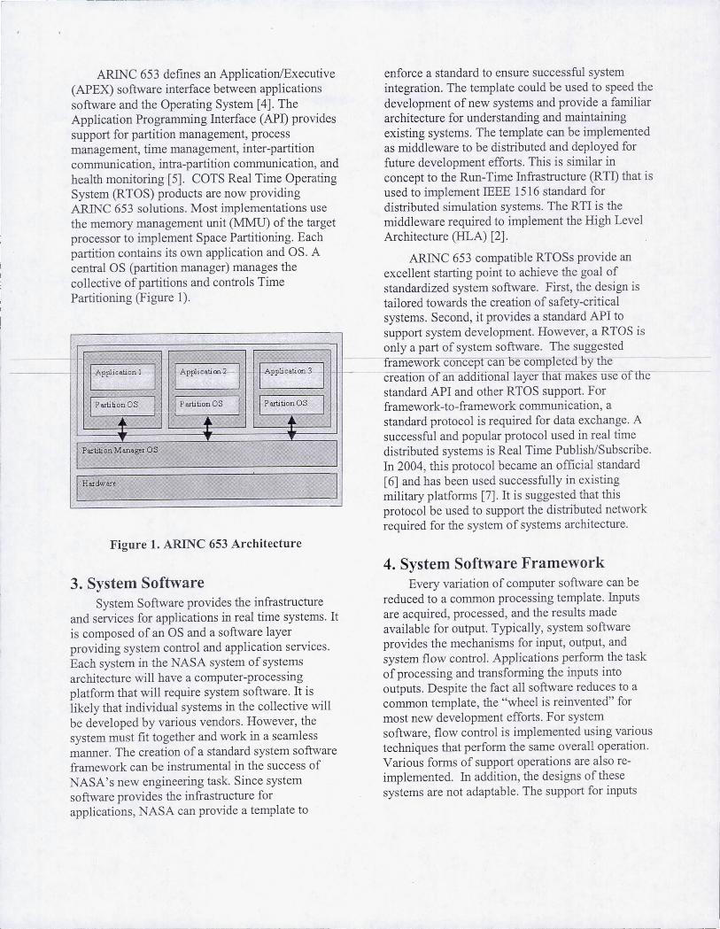
ARINC 653 defines an Application/Executive (APEX) software interface between applications software and the Operating System [4]. The Application Programming Interface (APD provides support for partition management, process management, time management, inter-partition communication, intra-partition communication, and health monitoring [5]. COTS Real Time Operating System (RTOS) products are now providing ARINC 653 solutions. Most implementations use the memory management unit (MMU) of the target processor to implement Space Partitioning. Each partition contains its own application and OS. A central OS (partition manager) manages the collective of partitions and controls Time Partitioning (Figure 1).
I-APplication 1- 1 I Application2-
1
I Application 3 -I I Partition OS I I Partition as I I PartitionOS I I I • ... ...
l' l'
PartitionManager as
I Hardware
,
I
Figure 1. ARINC 653 Architecture
3. System Software System Software provides the infrastructure
and services for applications in real time systems. It is composed of an OS and a software layer providing system control and application services. Each system in the NASA system of systems architecture will have a computer-processing platform that will require system software. It is likely that individual systems in the collective will be developed by various vendors. However, the system must fit together and work in a seamless manner. The creation of a standard system software framework can be instrumental in the success of
ASA's new engineering task. Since system software provides the infrastructure for applications, NASA can provide a template to
enforce a standard to ensure successful system integration. The template could be used to speed the development of new systems and provide a familiar architecture for understanding and maintaining existing systems. The template can be inlplemented as middleware to be distributed and deployed for future development efforts. This is similar in concept to the Run-Time Infrastructure (RTD that is used to implement IEEE 1516 standard for distributed simulation systems. The RTI is the middleware required to implement the High Level Architecture (HLA) [2].
ARINC 653 compatible RTOSs provide an excellent starting point to achieve the goal of standardized system software. First, the design is tailored towards the creation of safety-critical systems. Second, it provides a standard API to support system development. However, a RTOS is only a part of system software. The suggested fiamewor concept can e completed by tne-creation of an a TIona layer that m es use ofThT standard API and other RTOS support. For framework-to-framework communication, a standard protocol is required for data exchange. A successful and popular protocol used in real time distributed systems is Real Time Publish/Subscribe. In 2004, this protocol became an official standard [6] and has been used successfully in existing military platforms [7]. It is suggested that this protocol be used to support the distributed network required for the system of systems architecture.
4. System Software Framework Every variation of computer software can be
reduced to a common processing template. Inputs are acquired, processed, and the results made available for output. Typically, system software provides the mechanisms for input, output, and system flow control. Applications perform the task of processing and transforming the inputs into outputs. Despite the fact all software reduces to a common template, the "wheel is reinvented" for most new development efforts. For system software, flow control is implemented using various techniques that perform the same overall operation. Various forms of support operations are also reimplemented. In addition, the designs of these systems are not adaptable. The support for inputs
and outputs are intertwined with the processin a to provide a function interface and if this interface logic. b is constantly changing (function protocol, function
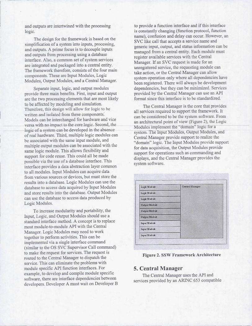
The design for the framework is based on the name), confusion and delay can occur. However, an simplification of a system into inputs, processing, SVC like call that accepts a service name and and outputs. A prime focus is to decouple inputs generic input, output, and status information can be and outputs from processing using a database managed from a central entity. Each module must interface. Also, a common set of system services register available services with the Central are integrated and packaged into a central entity. Manager. If an SVC request is made for an The framework therefore, consists of the four main unregistered service, the requesting module can components . These are Input Modules, Logic take action, or the Central Manager can allow Modules, Output Modules, and a Central Manager. system operation only where all dependencies have
been registered . There will always be development Separate input, logic, and output modules dependencies, but they can be minimized. Services
provide three main benefits. First, input and output provided by the Central Manager can use an API are the two processing elements that are most likely format since this interface is to be standardized. to be affected by modeling and simulation. Therefore, this design will allow for logic to be The Central Manager is the core that provides written and isolated from these components: all services required to support the framework. It Models can be interchanged for hardware and vice can be considered to be the system software. From
--veT-sa with-no impacUo the core logic. Second, the ___ ~an architectural point of view (Figure 2), the Logic --logic of a syst€-m can be-d€-velop€-d in th~bsence- 0 u es Imp ement1be-
cc
aomain" logic for a of real hardware. Third, multiple logic modules can system. The put MOaules, Output :rY:loaules, an be associated with the same input module, and Central Manager provide support to realize the muitipie output moduies can be associated with the "domain" logic. The Input Modules provide support same logic module. This allows flexibility and for data acquisition, the Output Modules provide support for code reuse. This could all be made support for operations such as commanding and possible via the use of a database interface. This displays, and the Central Manager provides the interface provides a data abstraction layer common system software. to all modules. Input Modules can acquire data from various sources or devices, but must store the results into a database. Logic Modules can use the database to access data acquired by Input Modules and store results into the database. Output Modules can use the database to access data produced by Logic Modules.
To increase modularity and portability, the Input, Logic, and Output Modules should use a standard interface method. A concept is to replace most module-to-module API with the Central Manager. Logic Modules may need to work together to perform activities. This can be implemented via a single interface command (similar to the OS SVC Supervisor Call command) to make the request for services. The request is routed to the Central Manager to dispatch the service. This can eliminate the problems with module specific API function interfaces. For example, to develop and compile module specific software, there are interface dependencies between developers. Developer A must wait on Developer B
LOCi: Modult CeJlo-...lMa..JSa;er
Lo,", Mod ult
Lo,i: Modult
Ouiput Modult
Ouip"j Mod1lle
Output Mod1lle
Inp"t Module
Inp"t Module
Inp.t Module
Figure 2. SSW Framework Architecture
5. Central Manager The Central Manager uses the API and
services provided by an ARINC 653 compatible
J

----.--~------
RTOS to implement a standard system software layer. This layer provide·s services to and controls the Input, Logic, and Output Modules of the framework. It is composed of a Registration Manager, Time and Event Sequence Manager, Service Manager, Health Manager, Configuration Manager, InitializationfPatch Manager, Telemetry/Logging Manager, External System and Heartbeat Manager, Database Manager, Data Publishing Manager, and Data Subscription Manager (Figure 3).
CenJrtd Jl.-Jiuwger
~ !Jte&istraWnMam&"'"
I I[·~
I . :"'''l:''I"lPail:h M",lOgI!T
I Tin..". am Eve>1t Ba<ed SeqlEllClll" I !~~~~ I
, !~~~ I I EXU!nlaI S)"Stem am
Heariboot Mall3ger I ! HealthM~
I ! DataPli>lishingl\~
I I Co",~iion Managu-
I I Data Subs~ tion Manager
I I
I I
I i I"~~ I
Figure 3. Framework Central Manager
The Registration Manager provides a registration interface between modules and the Central Manager. Modules can register services to be used by other modules and can register for services provided by other modules. Modules can also register for read/write access to parameters in the database. A registration interface provides a runtime method to provide and acquire services. This allows modules to be added and removed from the system without a total recompile. This benefit is only available if the supporting RTOS provides the capability for dynamic loading and linking of multiple object files.
The Timer and Event Sequencer provide the se0'ice required to invoke modules based on either a timer or events. It implements the flow control for
the system. The sequencer provides a hybrid infrastructure supporting an executive, priority based task manager, and state machines. The sequencer is implemented using RTOS services such as Process Control and Event Management. It provides the concept of major and minor cycles to structure cyclic operations. Input, Logic, and Output Modules are associated with one or more sequencer control methods.
The Service Manager provides the single SVC interface in support of module-based services. Modules register the intent to provide services using the Registration Manager. The Service Manager invokes the module service when requested via the interface.
The Health Manager provides a centralized system error handler. The system could provide an API to be called by each module to report error
- conditions.Jhe manage woulcLconsist oLa table mapping-error-conclitions to policy functions The policy function performs actions in response to errors. This could work with the Configuration Manager to determine how to configure or safe the system in response to failures and reconfigure after recovery. It could also be implemented using fault trees in support of the analysis of error paths. ARINC 653 provides an interface and services for health management. This manager could use the ARINC interface to implement this service. A benefit is that the framework version can be integrated to work with the other framework modules to provide advanced capability.
The Configuration Manager configures the system based on system state. It contains tables that map the relationships for modules and data sources required for proper operation. It interfaces with the Registration Manager, Health Manager, and the External System and Heartbeat Manager to analyze system state for modules. It also interfaces with the Timer and Event Sequencer to activate or deactivate the operation of modules. For example, if Module A depends on Module B and data from an external module for proper operation and Module B has not been registered, then Module A would not be allowed to execute. Also, if Module A is operational, but data from the external module is no longer available, then Module A will be shutdown until the data is operational in the future.
The InitializationlPatch Manager provides an interface to allow for module initialization. The intent is to load an object file and invoke an initialization function for each Input, Logic, and Output Module. The concept of a separate object file for each module provides support for flexible and dynamic systems. New capability can be incorporated without a system recompile and existing modules can be temporarily replaced to support simulation. The initialization function for each module can include all logic required to initialize that module including the use of the Registration Manager API to register services and other required items. The manager also provides support for patch capability. The simplest approach
The Data Publishing Manager provides the service to send data to remote systems collected from the database. The Data Subscription Manager provides the service to receive data from remote systems to store into the database. Each uses the Real Time Publish/Subscribe protocol.
6. Example Design Implementation This section provides a concept of execution
using the framework concept. It first provides the configuration of a hypothetical system and then follows with scenarios through various lifecycles and system operation.
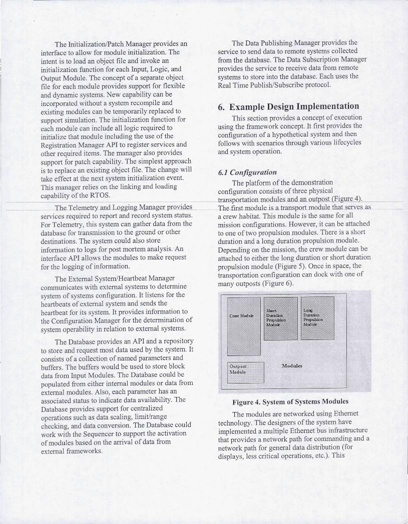
is to replace an existing object file. The change will 6.1 Configuration take effect at the next system initialization event. This manager relies on the linking and loading The platform of the demonstration capability of the RTOS. configuration consists of three physical
------------__ transportation..modules and an outpost (Figure 4 . --- Ihe..Telemetry and Logging Manager provides The firsLmodulei s_a transpor:t module that seJYes as
services required to report and record system status. a crew habitat. This module is the same for all For Telemetry, this system can gather data from the mission configurations. However, it can be attached database for transmission to the ground or other to one of two propulsion modules . There is a short destinations . The system could also store duration and a long duration propulsion module. information to logs for post mortem analysis. An Depending on the mission, the crew module can be interface API allows the modules to make request attached to either the long duration or short duration for the logging of information. propulsion module (Figure 5). Once in space, the
The External System/Heartbeat Manager transportation configuration can dock with one of communicates with external systems to determine many outposts (Figure 6). system of systems configuration. It listens for the heartbeats of external system and sends the heartbeat for its system. It provides information to the Configuration Manager for the detemtination of system operability in relation to external systems.
The Database provides an API and a repository to store and request most data used by the system. It consists of a collection of named parameters and buffers. The buffers would be used to store block data from Input Modules. The Database could be populated from either internal modules or data from external modules. Also, each parameter has an associated status to indicate data availability. The Database provides support for centralized operations such as data scaling, limit/range checking, and data conversion. The Database could work with the Sequencer to support the activation of modules based on the arrival of data from external franleworks .
I
Srort Lo~ Creov Mod ule Duratiln Duration
Propulsion Propulsion Module Module
I
Outpost Modules
I MIldule
Figure 4. System of Systems Modules
The modules are networked using Ethernet technology. The designers of the system have implemented a mUltiple Ethernet bus infrastructure that provides a network path for commanding and a network path for general data distribution (for displays, less critical operations, etc.). This
j
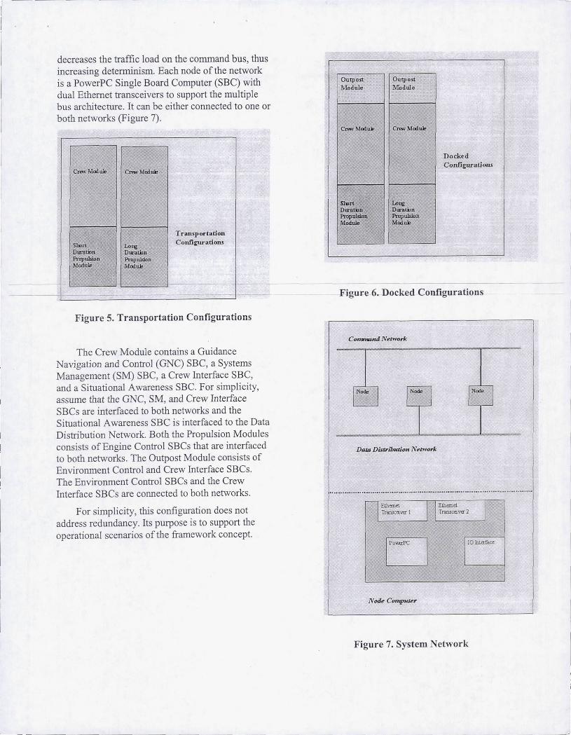
decreases the traffic load on the command bus, thus increasing determinism. Each node of the network is a PowerPC Single Board Computer (SBe) with dual Ethernet transceivers to support the multiple bus architecture. It can be either connected to one or both networks (Figure 7) .
Crew Madu.ie Crew Moduie
I I
I Sh ut Durntim Propumon Module
Lo.-g Duratim Propulsion Madill!
T ransportation Configurations
Figure 5. Tr ansportation Configurations
The Crew Module contains a Guidance Navigation and Control (GNe) SBC, a Systems Management (SM) SBC, a Crew Interface SBC, and a Situational Awareness SBC. For simplicity, assume that the ONC, SM, and Crew Interface SBCs are interfaced to both networks and the Situational Awareness SBC is interfaced to the Data Distribution Network. Both the Propulsion Modules consists of Engine Control SBCs that are interfaced to both networks. The Outpost Module consists of Environment Control and Crew Interface SBCs. The Environment Control SBCs and the Crew Interface SBCs are connected to both networks.
For simplicity, this configuration does not address redundancy. Its purpose is to support the operational scenarios of the framework concept.
outpost Module
Crew Modlll!
Smrt DuratiJn Propulsion Module
Outpost Module
Crew Module
Lore: Durawn Propulsion Module
Docked Confj~ations
Figure 6. Docked Configurations
Command Network
I -------Dam Distrilnuion NetJVork
1 Ethernet Transceiver 1 1 1 Eth=el Transceiva" 2 1
LJ 10 Interlace
N ode COmpuier
Figure 7. System Network
I -I
I
J
r I 6.2 Node Interface Technology
For this sample implementation, the framework is implemented using VxWorks ARINC 653 for OS support, NDDS for network support, and a PowerPC hardware platform (Figure 8) .
SSW Framework
VxWorks ARlNC 653 I NDDS I PowerPC sac
PowerPC SBe
Figure 8. System Implementation
6.3 Crew Module Computer Requirements
The GNC computer reads hardware instruments to determine the location anL _ . __
- - - orientation of-the-vehicle and sends commands to the Propulsion Modules for control.
The GNC computer can receive commands from the Crew Interface Module to adjust the behavior of the output commands.
The GNC computer uses independent algorithms for the control of the two Propulsion Modules.
In the Docked Configuration, the GNC Computer enters a safe mode to prevent activity with the Propulsion Modules.
In the Docked Configuration, the G C Computer is connected to a simulator where the crew can practice maneuvers using the actual spacecraft interface.
The GPC computer will enter a safe mode if it fails to communicate the Propulsion Modules.
The SM computer receives commands from the Crew Interface computers of the Crew Module and Outpost Module.
The SM computer sends display data over the Data Distribution Network.
The Crew Interface computer sends crew commands over the Command etwork.
The Situational Awareness computer receives data over the Data Distribution Network and displays information to the crew.
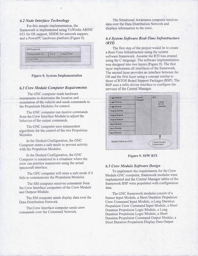
6.4 System Software Real-Time Infrastructure (RTlJ
The first step of the proj ect would be to create a Real-Time Infrastructure using the system software framework. Assume the RTI was created using the C language. The software implementation was designed into two layers (Figure 9). The first layer implements all interfaces of the framework. The second layer provides an interface between the OS and the first layer using a concept similar to those ofRTOS Board Support Packages (BSP). The BSP uses a table driven interface to configure the services of the Central Manager.
L~Module Central BSP Mal",_
L~Module Tables RTQS
L~Module lnierface
Quip ut Module
Ouq>utModule
Quip ut Module
I", ut Module
hputModule
l'1'utModule
1 System Software RT! Centr.!! Manag,,"
Requirements
Figure 9. SSW RTI
6.5 Crew Module Software Design To implement the requirements for the Crew
Module GNC computer, framework modules were implemented and the Central Manager tables of the fran1ework BSP were populated with configuration data.
The GNC fran1ework modules consist of a Sensor Input Module, a Short Duration Propulsion Crew Command Input Module, a Long Duration Propulsion Crew Command Input Module, a Short Duration PropUlsion Logic Module, a Long Duration Propulsion Logic Module, a Short Duration PropUlsion Command Output Module, a Short Duration Propulsion Display Data Output
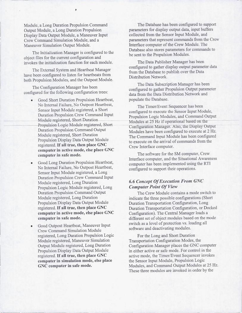
Module, a Long Duration Propulsion Command Output Module, a Long Duration Propulsion Display Data Output Module, a Maneuver Input Crew Command Simulation Module, and a Maneuver Simulation Output Module.
The Initialization Manager is configured to the object files for the current configuration and invokes the initialization function for each module.
The External System and Heartbeat Manager have been configured to listen for heartbeats from both Propulsion Modules, and the Outpost Module.
The Configuration Manager has been configured for the following configuration trees:
• Good Short Duration Propulsion Heartbeat, No Internal Failure, No Outpost Heartbeat, Sensor Input Module registered, a Short Duration Propulsion Crew Command Input
-------,Module-registered,-Short Duration -------Propulsion bogiG- Modul€-F€-gist€-F€-d, £h0l;t
Duration Propulsion Command Output Module registered, Short Duration Propulsion Display Data Output Module registered. If all true, then place GNC computer in active mode, else place GNC computer in safe mode.
• Good Long Duration Propulsion Heartbeat, No Internal Failure, No Outpost Heartbeat, Sensor Input Module registered, a Long Duration Propulsion Crew Command Input Module registered, Long Duration PropUlsion Logic Module registered, Long Duration Propulsion Command Output Module registered, Long Duration Propulsion Display Data Output Module registered. If all true, then place GNC computer in active mode, else place GNC computer in safe mode.
• Good Outpost Heartbeat, Maneuver Input Crew Command Sinmlation Module registered, Long Duration Propulsion Logic Module registered, Maneuver Simulation Output Module registered, Long Duration Propulsion Display Data Output Module registered. If all true, then place GNC computer in simulation mode, else place GNC computer in safe mode.
- --- ... __ .. ---=
The Database has been configured to support paranleters for display output data, input buffers collected from the Sensor Input Module, and parameters that represent commands from the Crew Interface computer of the Crew Module. The Database also stores parameters for commands to be sent to the Propulsion Modules.
The Data Publisher Manager has been configured to gather display output parameter data from the Database to publish over the Data Distribution Network.
The Data Subscription Manager has been configured to gather PropUlsion Output parameter data from the Data Distribution Network and populate the Database.
The TimerlEvent Sequencer has been configured to execute the Sensor Input Module, Propulsion Logic Modules, and Command Output
~oaUles at 25 Hz ifoperational based on tile -coi1flguranon anager. A so, lie Isplay Output
Modules have been configured to execute at 2 Hz. The Command Input Module has been configured to execute on the arrival of commands from the Crew Interface computer.
The software for the SM computer, Crew Interface computer, and the Situational Awareness computer has been implemented using the RTI configured to support their operations.
6.6 Concept Of Execution From GNC Computer Point Of View
The Crew Module contains a mode switch to indicate the three possible configurations (Short Duration Transportation Configuration, Long Duration Transportation Configuration, or Docked Configuration). The Central Manager loads a different set of object modules based on the mode switch as a level of protection vs. loading all software and deactivating modules.
F or the Long and Short Duration Transportation Configuration Modes, the Configuration Manager places the GNC computer in either active or safe mode. For control in the active mode, the TimerlEvent Sequencer invokes the Sensor Input Module, Propulsion Logic Modules, and Command Output Modules at 25 Hz. These three modules are invoked in order by the
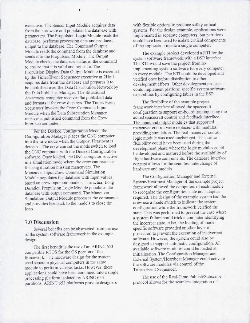
executive. The Sensor Input Module acquires data from the hardware and populates the database with parameters. The Propulsion Logic Module reads the database, performs processing data and produces output to the database. The Command Output Module reads the command from the database and sends it to the Propulsion Module. The Output Module checks the database status of the conunand to ensure that it is valid and not stale. The Propulsion Display Data Output Module is executed by the TimerlEvent Sequencer executive at 2Hz. It acquires data from the database and prepares it to be published over the Data Distribution Network by the Data Publisher Manager. The Situational Awareness computer receives the published data
~ ~--- - - ..... - -----
with flexible options to produce safety critical systems. For the design example, applications were implemented in separate computers, but partitions could have been used to isolate critical components of the application inside a single computer.
The example project developed a RTI for the system software framework with a BSP interface. The RTI would save the project from reimplementing system software for every computer in every module. The RTI could be developed and verified once before distribution to other development efforts . Other development projects could implement platform specific system software capabilities by configuring tables in the BSP.
and formats it for crew displays. The Timer/Event The flexibility of the example project Sequencer invokes the Crew Command Input framework interface allowed the spacecraft Module when the Data Subscription Manager configuration to support on-board training using the receives a published command from the Crew actual spacecraft control and feedback interface. Interface computer. ___ . ___ The input and output modules that supported
t - 1; -C fi- h Mi - th JllaneUyeLcontmaer~e r.-eplaced with modules or e OCl\.e on gurallon 0 e, e 'd' . l' Th I I
C fi f M 1 th GNC t prov! mg Slmu atlOn. e rea maneuver contro . on 19ura IOn anager paces e compu .er logic module was used unchanged. This same mto the safe mode when the Outpost Heartbeat IS .l'1 'b'l ' Id h 1-. d d' h d t t d Th t th d 't h tId HeXl i Ity cou ave ueen use urmg t e e ec e. e crew can se e mo e SWI c 0 oa . th GNC t ·th th D k d C fi t ' development phase where the lOgIC modules could
e compu er WI e oc e on 19ura IOn b d 1 . . . ftw 0 1 d d th GNC t
· t' e eve oped and matured before the avaIlabIlIty of so are. nce oa e , e compu er IS ac Ive fl' . . . I h d h th t' Ight hardware components. The database mterface m a Slmu aLlon mo e were e crew can prac Ice . fi 1 d t
· . . Th concept allows for the seamless mterchange of or ong ura IOn rrusslOn maneuvers. e h d d d 1
M In C C d S· l ' ar ware an mo e s. aneuver put rew omman Imu atlOn
Module populates the database with input values based on crew input and models. The actual Long Duration Propulsion Logic Module populates the database with output command. The Maneuver Simulation Output Module processes the conunands and provides feedback to the models to close the loop.
7.0 Discussion Several benefits can be abstracted from the use
of the system software franlework in the example design.
The first benefit is the use of an ARINC 653 compatible RTOS for the OS portion of the framework. The hardware design for the system used separate physical computers in the same module to perform various tasks. However, these applications could have been combined into a single processing platfoml isolated by ARINC 653 partitions. ARINC 653 platforms provide designers
The Configuration Manager and External SystemlHeartbeat Manager of the example project framework allowed the computers of each module to recognize the configuration state and adapt as required. The design of the exanlple system had the crew use a mode switch to indicate the system configuration while the framework verified the state. This was performed to prevent the case where a system failure could trick a computer identifying the incorrect state. Also, the loading of mode specific software provided another layer of protection to prevent the execution of inadvertent software. However, the system could also be designed to support automatic configuration. All available software modules could be loaded at initialization. The Configuration Manager and External System/Heartbeat Manager could activate the software modules via control of the TimerlEvent Sequencer.
The use of the Real-Tinle Publish/Subscribe protocol allows for the seamless integration of
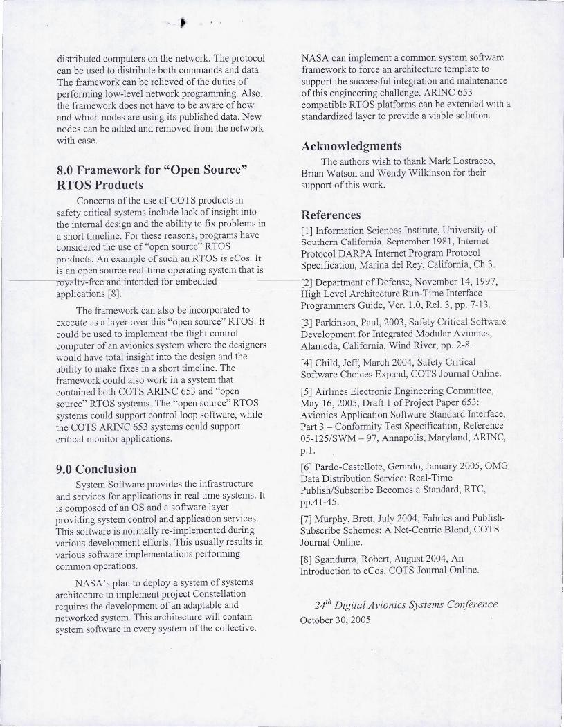
• distributed computers on the network. The protocol can be used to distribute both commands and data. The framework can be relieved of the duties of performing low-level network programming. Also, the framework does not have to be aware of how and which nodes are using its published data. New nodes can be added and removed from the network with ease.
8.0 Framework for "Open Source" RTOS Products
Concerns of the use of COTS products in safety critical systems include lack of insight into the internal design and the ability to fix problems in a short timeline. For these reasons, programs have considered the use of "open source" RTOS products. An example of such an RTOS is eCos. It is an open source real-time operating system that is
- ---rCJyalt)r-fre-e-and ·ntended-for embedded-applicafions [8].
The framework can also be incorporated to execute as a layer over this "open source" RTOS . It could be used to implement the flight control computer of an avionics system where the designers would have total insight into the design and the ability to make fixes in a short timeline. The fran1ework could also work in a system that contained both COTS ARINC 653 and "open source" RTOS systems. The "open source" RTOS systems could support control loop software, while the COTS ARINC 653 systems could support critical monitor applications.
9.0 Conclusion System Software provides the infrastructure
and services for applications in real time systems. It is composed of an OS and a software layer providing system control and application services. This software is normally re-implemented during various development efforts. This usually results in various software implementations perfom1ing common operations.
NASA's plan to deploy a system of systems architecture to implement proj ect Constellation requires the development of an adaptable and networked system. This architecture will contain system software in every system of the collective.
---._--
NASA can implement a common system software framework to force an architecture template to support the successful integration and maintenance of this engineering challenge. ARINC 653 compatible RTOS platforms can be extended with a standardized layer to provide a viable solution.
Acknowledgments The authors wish to thank Mark Lostracco,
Brian Watson and Wendy Wilkinson for their support of this work.
References [1] Information Sciences Institute, University of Southern California, September 1981 , Internet Protocol DARPA Internet Program Protocol Specification, Marina del Rey, California, Ch.3.
[L.] Department of Defense, November 14, 1997-, -Rig eve -Mchi ectUfe Run-Time Interface Programmers Guide, Ver. 1.0, ReI. 3, pp. 7-13 .
[3] Parkinson, Paul, 2003, Safety Critical Software Development for Integrated Modular Avionics, Alameda, California, Wind River, pp. 2-8.
[4] Child, Jeff, March 2004, Safety Critical Software Choices Expand, COTS Journal Online.
[5] Airlines Electronic Engineering Committee, May 16, 2005, Draft 1 of Project Paper 653: Avionics Application Software Standard Interface, Part 3 - Conformity Test Specification, Reference 05-125/SWM - 97, Annapolis, Maryland, ARINC, p.l.
[6] Pardo-Castellote, Gerardo, January 2005, OMG Data Distribution Service: Real-Time Publish/Subscribe Becomes a Standard, RTC, pp.41-45.
[7] Murphy, Brett, July 2004, Fabrics and PublishSubscribe Schemes: A Net-Centric Blend, COTS Journal Online.
[8] Sgandurra, Robert, August 2004, An Introduction to eCos, COTS Journal Online.
24th Digital Avionics Systems Conference
October 30, 2005