Embed Size (px)
Citation preview
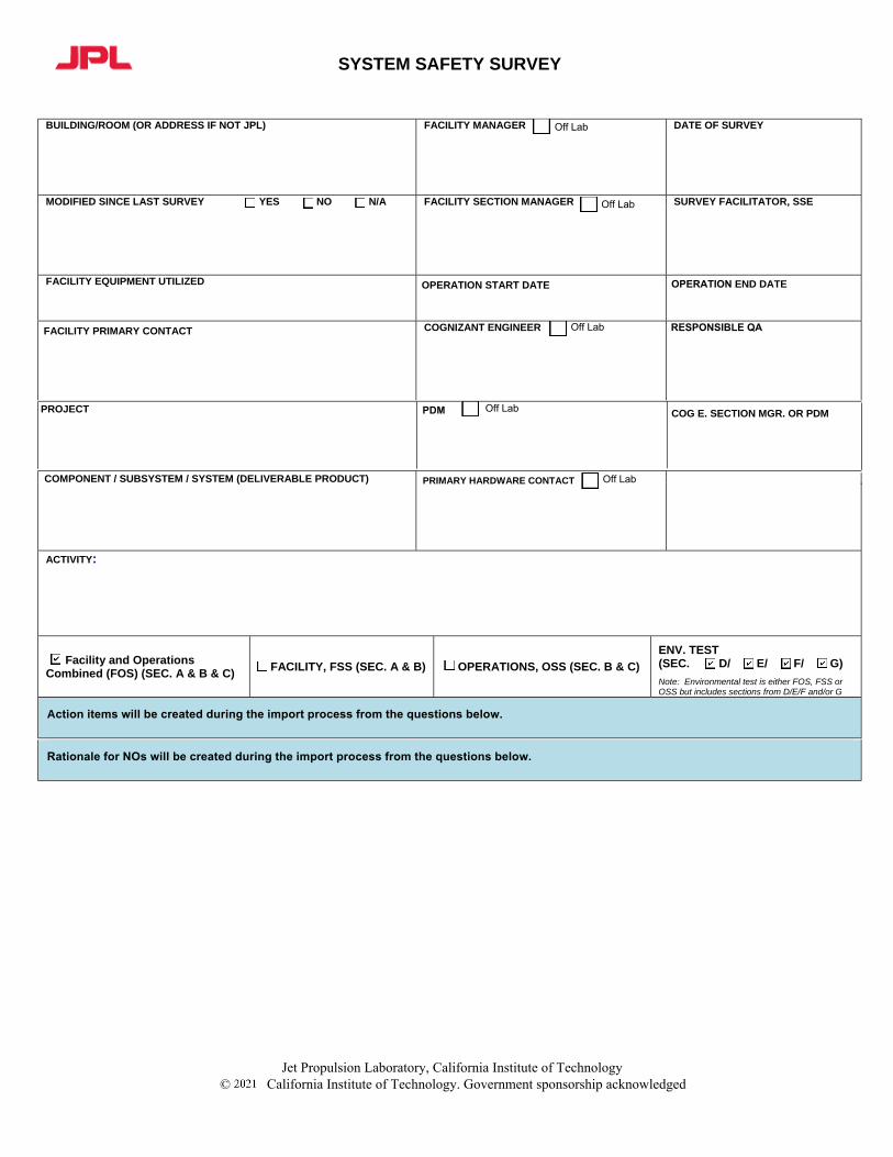
SYSTEM SAFETY SURVEY
BUILDING/ROOM (OR ADDRESS IF NOT JPL) FACILITY MANAGER DATE OF SURVEY
MODIFIED SINCE LAST SURVEY YES NO N/A FACILITY SECTION MANAGER SURVEY FACILITATOR, SSE
FACILITY EQUIPMENT UTILIZED
FACILITY PRIMARY CONTACT
OPERATION START DATE
PROJECT
COGNIZANT ENGINEER
OPERATION END DATE
COMPONENT / SUBSYSTEM / SYSTEM (DELIVERABLE PRODUCT) PRIMARY HARDWARE CONTACT
ACTIVITY:
Facility and Operations Combined (FOS) (SEC. A & B & C)
FACILITY, FSS (SEC. A & B) OPERATIONS, OSS (SEC. B & C)
ENV. TEST (SEC. D/ E/ F/ G)
Note: Environmental test is either FOS, FSS or OSS but includes sections from D/E/F and/or G
Action items will be created during the import process from the questions below.
RESPONSIBLE QA
PDM COG E. SECTION MGR. OR PDM
Off Lab
Off Lab
Off Lab
Off Lab
Off Lab
Rationale for NOs will be created during the import process from the questions below.
Jet Propulsion Laboratory, California Institute of Technology California Institute of Technology. Government sponsorship acknowledged©

SYSTEM SAFETY SURVEY
LIST OF ATTENDEES
Name Organization/Function/Off Lab Email
Name Organization/Function/Off Lab Email
HAZARDOUS AGENTS / CONDITIONS
TYPES* HAZARD DESCRIPTION QTY, VOLTAGE, PRESSURE,
TEMPERATURE, ETC. (RANGE)
CONTROL MEASURES(s) (No.)**
Jet Propulsion Laboratory, California Institute of Technology California Institute of Technology. Government sponsorship acknowledged©

SYSTEM SAFETY SURVEY
TYPES* HAZARD DESCRIPTION QTY, VOLTAGE, PRESSURE,
TEMPERATURE, ETC. (RANGE)
CONTROL MEASURES(s) (No.)**
*HAZARDOUS TYPE KEY
**HAZARDOUS CONTROL MEASURE KEY C1. Safety Glasses C2. Goggles (list type)C3. Faceshield C4. Hearing Protection C5. Particulate Respirator C6. Chemical Respirator C7. Self-Contained
Breathing Apparatus C8. Barrier Creams
C9. Gloves (list type)C10. Apron C11. Lab Coat / CoverallsC12. Bunny Suit C13. Shielding or BarrierC14. Oxygen DetectorC15. Ventilation C16. Chemical Fume Hood
C17. Stand-by Neutralize C18. Double Containment C19. Lock Out / Tag Out / Procedures C20. Waste Disposal Can C21. Satellite Waste Accumulation Point C22. Wrist Straps C23. Insulated Ground Straps C24. Conductive Garments
C25. Conductive Transporters C26. Cleanliness C27. Thermal Insulation C28. Automatic Fire Sprinklers C29. Portable Fire Extinguishers C30. Battery Charging, Handling & Storage Procedure
C31. Other:______________ C32. Other:______________
Operation: Attended Unattended After Hours TV Surveillance Buddy System Remote
Safety warnings: Signs Lights Alarms JPL Console Alarm Other:
EMISSIONS, DISCHARGES, AND WASTES
WASTE GENERATED RATE e.g., grams/hr
YEARLY TOTAL e.g., grams, liters
ROUTINE DISPOSAL NON-ROUTINE DISPOSAL
1. Acoustics2. Biohazards3. Carcinagens4. Chemicals5. Cryogens6. Confined Spaces7. Contamination8. Contamination Sources
9. Electric Equipment10. ESD11. Explosives12. Flammable Gases13. Flammable Liquids14. High Voltage >600 Volts15. High Temperature16. Humidity / Water
17. Lasers18. Lifting / Elevators19. Loss of Power20. Low Illumination21. Low Temperatures22. Oxidizer23. Oxygen Deficiency24. Physical Hazards
25. Pyrophonic26. Pressure / Vacuum System27. Process Tanks28. Radiation (ionizing)29. Radiation (non-ionizing)30. Reproductive Toxins31. Toxic Materials32. Use Clean Agents for Fires
33. Water Reactives34. Vibration35. Battery (non-UL)36. Other: ____________37. Other: ____________38. Other: ____________
Jet Propulsion Laboratory, California Institute of Technology California Institute of Technology. Government sponsorship acknowledged©

SYSTEM SAFETY SURVEY
ENVIRONMENTAL COMPLIANCE CHECKLIST
It is the responsibility of the facility & operations managers to ensure that their work practices provide for compliance with JPL practices regarding environmental protection. For more information, please contact the Environmental Affairs Program Office.
Remarks: YES NO N/A TRAINING
1. All required Environmental Training is up to date.Contact the Environmental Affairs Program Office (EAPO) for status of training (https://osms.jpl.nasa.gov/503)
HAZARDOUS WASTE – Waste which is: ignitable, corrosive, toxic, or reactive. Also, waste contaminated with chemicals (wipes, syringes, empty bottles that held chemicals, etc.) 2. Arrangements for all hazardous waste pick-up must be completed by EAPO (ext. 4-0635) without exception.
3. Employees handling hazardous waste are trained and training is current.
4. Each container of hazardous waste is properly labeled with a form generated by the JPL Hazardous Waste Generator Tool(https://hazwastetracking.jpl.nasa.gov/tickets) or JPL form 2799.
5. No hazardous waste placed in blue recycle bin, office trash can or in outside dumpster. (Hazardous waste must be stored indoorsat or near point of generation.)
AIR QUALITY 6. Copy of the permit (i.e., the latest revision) for permitted equipment posted at the location of the equipment (e.g. generators,
boilers, spray booths, vapor degreasers, etc.)
7. Used or contaminated rags or wipes contained in a closed container when not in use.
WASTEWATER / STORMWATER 8. Advance approval obtained from EAPO before any material is placed, dumped, or washed into the sanitary sewer system (sinks,
toilets, or other drains). This includes cooling water, rinse water, steam cleaning, etc.
9. No materials of any kind will be washed into the storm drain system.
Jet Propulsion Laboratory, California Institute of Technology California Institute of Technology. Government sponsorship acknowledged©

SYSTEM SAFETY SURVEY
EPA REGULATED SOLVENTS APPROVED ONLY FOR FLIGHT HARDWARE USE NOTE: When approved by the specific project, these ozone-depleting solvents may be used for flight hardware cleaning operations in addition to the traditionally approved alcohol acetone. These solvents may NOT be used for non-flight hardware cleaning operations except as noted in note 1 below. Indicate below which solvents are planned to be used, if any.
USE USE 1,1,1 – Trichloroethane (methyl chloroform) 1,1,2,2,3 – Pentafluoropropane (HFC-245ca)
Trichlorofluoromethane (CFC-11) 1,1,2,3,3 – Pentafluoropropane (HFC-245ea)
Dichlorodifluoromethane (CFC-12) 1,1,1,2,3 – Pentafluoropropane (HFC-245eb)
1,1,2 – Trichloro – 1,2,2 trifluoroethane (CFC-113) 1,1,1,3,3 – Pentafluoropropane (HFC-245fa)
1,2 – Dichloro – 1,1,2,2 –tetrafluoroethane (CFC-114) 1,1,1,2,3,3 – Hexafluoropropane (HFC-236ea)
Chloropentafluoroethane (CFC-115) 1,1,1,3,3 – Pentafluorobutane (HFC-365mfc)
Cyclic, branched, or linear, completed methylated siloxanes Chlorofluoromethane (HCFC-31)
Ethylfluoride (HCH-161) 1,2 – Dichloro – 1,1,2 – trifluoroethane (HCFC-123a)
1,1,1,3,3,3 – Hexafluoropropane (HFC-236fa) 1 – Chloro – 1-fluoroethane (HCFC-151a)
Constraints / Notes: 1. These solvents may be used for research purposes in non-cleaning applications.2. These are ozone-depleting compounds and should not be used for cleaning except in applications where no non-ozone depleting
substance has been identified as an acceptable alternative.3. The word “cleaning” refers to “wipe-cleaning” or “hand-held spray bottles from which solvents are applied without a propellant-
induced force.”4. For cleaning processes where a solvent-holding tank (such as ultrasonic cleaners) is used, air permits may be required before such
equipment can be used. Please contact EAPO for further assistance.5. The only solvents on this list currently used for flight hardware cleaning at JPL are 1,1,1 – Trichloroethane (Methyl Chloroform) and
1,1,2 – Trichloro – 1,2,2 – Trifluoroethane (Freon or CFC-113). Whenever possible, flight projects should also avoid using thesematerials and use non-ozone depleting alternatives instead, such as Brulin 815.
Jet Propulsion Laboratory, California Institute of Technology California Institute of Technology. Government sponsorship acknowledged©
SYSTEM SAFETY SURVEY
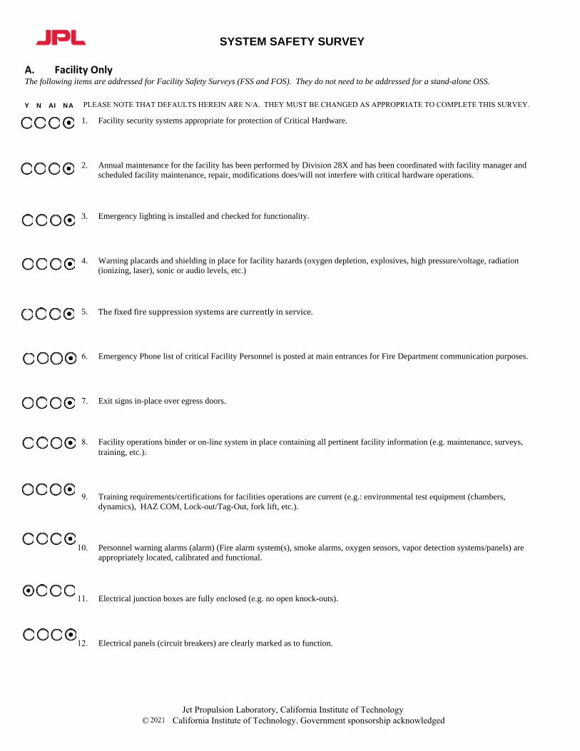
A. Facility OnlyThe following items are addressed for Facility Safety Surveys (FSS and FOS). They do not need to be addressed for a stand-alone OSS.
Y N AI NA
1. Facility security systems appropriate for protection of Critical Hardware.
2. Annual maintenance for the facility has been performed by Division 28X and has been coordinated with facility manager andscheduled facility maintenance, repair, modifications does/will not interfere with critical hardware operations.
3. Emergency lighting is installed and checked for functionality.
4. Warning placards and shielding in place for facility hazards (oxygen depletion, explosives, high pressure/voltage, radiation(ionizing, laser), sonic or audio levels, etc.)
5. Thefixedfiresuppressionsystemsarecurrentlyinservice.
6. Emergency Phone list of critical Facility Personnel is posted at main entrances for Fire Department communication purposes.
7. Exit signs in-place over egress doors.
8. Facility operations binder or on-line system in place containing all pertinent facility information (e.g. maintenance, surveys,training, etc.).
9. Training requirements/certifications for facilities operations are current (e.g.: environmental test equipment (chambers,dynamics), HAZ COM, Lock-out/Tag-Out, fork lift, etc.).
10. Personnel warning alarms (alarm) (Fire alarm system(s), smoke alarms, oxygen sensors, vapor detection systems/panels) areappropriately located, calibrated and functional.
11. Electrical junction boxes are fully enclosed (e.g. no open knock-outs).
12. Electrical panels (circuit breakers) are clearly marked as to function.
PLEASE NOTE THAT DEFAULTS HEREIN ARE N/A. THEY MUST BE CHANGED AS APPROPRIATE TO COMPLETE THIS SURVEY.
Jet Propulsion Laboratory, California Institute of Technology California Institute of Technology. Government sponsorship acknowledged©
SYSTEM SAFETY SURVEY
B. Facility and OperationsThe following items are addressed for all surveys (FOS, FSS, OSS). Items herein apply to both Facility and Operations and should be interpreted in this context: in some cases the responsibility is mutual, and in other cases the responsibilities/actions of either the facility personnel or the operations personnel may impact the other and need to be understood.
Y N AI NA
F O
F O
F O
1. Date of previous Facility Safety Survey __________. All action items are closed.
2. Area: Appropriate Extinguishing Agent available for hardware (e.g.: HALON, CO2, water, etc.) and personnelknowledgeable about where extinguisher located.
3. Area: Area has been adequately cleared to support activity (e.g. housekeeping).
4. Area: Equipment, including cables, distribution plumbing, is properly rated, routed, secured and labeled as to function asappropriate. Any broken/defective tools or equipment have been identified and removed from service or repaired.
5. Area: Equipment/cabinets and overhead items which could be hazardous to personnel/critical hardware during an earthquakeproperly secured.
6. Area: Flight hardware signs are posted in test areas.
7. Area: Hazardous obstructions/obstacles are removed or otherwise safed, including overhead structures/fixtures.
8. Area: Hazardous/flammable materials have been identified, minimized, properly contained.
9. Area: Safety Data Sheet (SDS) (a.k.a. Material Safety Data Sheet (MSDS)) current and readily available.
10. Area: Mechanical/electrical parts suitably guarded (belts, vents, gauges, rotating machinery, Ground Fault Circuitinterrupters, etc.)
11. Area: Unobstructed egress/ingress paths maintained to all emergency exits (30” minimum path maintained).
12. Area: Floor loading is within acceptable limits for all facility equipment and posted where necessary.
13. Contamination controls in place and maintained at appropriate levels.
PLEASE NOTE THAT DEFAULTS HEREIN ARE N/A. THEY MUST BE CHANGED AS APPROPRIATE TO COMPLETE THIS SURVEY.
Jet Propulsion Laboratory, California Institute of Technology California Institute of Technology. Government sponsorship acknowledged©

SYSTEM SAFETY SURVEY
Y N AI NA
F O
14. Crane log-book current with all required information included (anomalies, daily/monthly check-list, inspections, etc).
15. Crane umbrella utilized for lifts involving critical hardware or alternate approved protection in place and proof tags current.
16. Crane/hoisting operations: Pre-lift briefing conducted.
17. Crane: Cranes are grounded.
18. Cranes and/or other lifting/elevating devices have a list of qualified operators posted (available) and current.
19. Cranes, hoists, slings, fixtures, portable and other lifting equipment currently certified and proof tested. Crane certs posted.
20. Cranes/hoisting equipment: All lifting elements in the dynamic load path (between hook and JCI) have been proof tested.Proof tags are in place and current.
24. ESD precautionary measures/techniques are in place (e.g.: grounding, garments, wrist straps, insulated traveling groundstraps.) and verified by QA.
25. ESD survey completed for this operation and/or facility ESD protected areas, and facility ground connection verified.Date:___________________.
26. ESD: Ground straps that could contact electrical outlets are insulated, including traveling ground straps.
22. Design: Critical Hardware support equipment (e.g.: stands, fixtures, etc.) are in certification per Safety Requirements forMechanical Support Equipment for JPL Critical Items, DocID 35412.
23. Designed to “fail-safe” for personnel and critical hardware.
Jet Propulsion Laboratory, California Institute of Technology California Institute of Technology. Government sponsorship acknowledged©

SYSTEM SAFETY SURVEY
Y N AI NA
F O
27. Mishap/Incident notification person identified.
28. Personnel conducting hazardous operations involving exposure (e.g. radiation, chemical exposure) included in medicalsurveillance program.
29. Personnel have been familiarized with alarm systems and emergency evacuation procedure.
30. Personnel understand that, in case of emergency, personnel safety takes precedence, and returning to a safe state for hardwareis secondary.
31. Power cords, receptacles and power strips are not damaged and have no exposed wires/terminals.
32. Power receptacles have been checked for proper phasing and grounding (contact Facilities Maintenance and Operations,Section 2820, if unknown).
33. Power strip(s) have all power cord plugs fully engaged (no exposed terminals or plugs).
34. Power: All cabling, power extension cords are properly rated, sized, routed, secured, protected and labeled with no daisy-chaining.
35. Power: Appropriate lightning and isolation surge protection measures baselined / implemented.
36. Power: Electrical panels and disconnect switches are not blocked. Minimum working space of 36” deep x 30”wide maintained.
F O
37. Power: Facility and/or operations Electrical Ground Support Equipment (EGSE) configurations conform to code requirements,properly labeled, protected, fused, and insulated.
F O
38. Power: Hardware/ systems safe in power-off state (i.e. power is not required to remain safe).
39. Power: Vertically mounted power strip(s) are secured and have plugs fully engaged.
Jet Propulsion Laboratory, California Institute of Technology California Institute of Technology. Government sponsorship acknowledged©

SYSTEM SAFETY SURVEY
Y N AI NA
F O
F O
F O
F O
F O
F O
40. PPE: PPE (protective clothing/equipment) for personnel and hardware protection available for planned and contingencyconditions (e.g. smocks, bunny suits, bonnets, booties, wrist straps, etc.), and where needed verified by OSPO and training forPPE current as required.
41. PPE not provided by facility, is appropriate and JPL Forms 2693 are attached.
42. Pressure: GSE and facility pressure/vacuum vessels/systems conform to code requirements, components properly labeled,restrained, relieved, and tested/validated. Pressure/vacuum systems and components are in current certification under the JPLIn-service Inspection Program. (Note: The Pressure Systems Support group (Section 357G) maintains the database and canprovide status).
43. Procedure: Equipment maintenance manual(s) exist and maintenance records kept current.
44. Procedures: Emergency plan and procedures are in place covering contingencies for both facility and operation for events suchas earthquake, fire, loss of power or consumables, hazardous spill, brush fire, smoke contamination, etc.
45. Security: Access control appropriate and access lists are current.
46. Security: Area secured and checked by security during non-working hours.
47. Security: Emergency access to facility is adequate. Fire lanes are not blocked.
48. Security: Fire Department and JPL Security notified about special responses required for hardware and personnel safety.
49. Software: Test Software versions and parameters are up-to-date and under configuration management.
50. Test: Approved written detailed test procedures(s) and/or Inspection for Build, Assembly and Test (IBAT(s)) provided.
51. Test levels are approved and appropriate level of test constraints/inhibits implemented to protect critical hardware fromdamage due to over-test conditions (see 11 Points Regarding Test Plan Guidelines at end of survey).
52. Test: Communications properly coordinated and tested (i.e., test conductor, facility/hardware test personnel, emergency, etc.).
Jet Propulsion Laboratory, California Institute of Technology California Institute of Technology. Government sponsorship acknowledged©

SYSTEM SAFETY SURVEY
Y N AI NA
F O
53. Test: Personnel involved briefed on test objectives/conduct/procedures including potential hazards.
F O
F O
F O
54. Test: Displays and alarms are adequate to indicate in-and-out-of-specifications conditions.
55. Test: Buddy System is in effect when critical hardware is accessible or operating.
56. Test: Full time operator coverage available when JCI is operating/powered on or in an environment (e.g. thermal chamber) thatis operating/powered on. (Note: an exception may be made under certain conditions, and with the approval of the appropriatemanagers).
57. Test: Key test parameters (vital for flight hardware protection and verification) continuously and automatically recorded andincorporated in shut-down circuit as appropriate.
58. Test: Emergency phone list of critical test personnel is posted in the test area including Mishap notification personnel (e.g.Systems Safety, Section Manager, Project MAM)
59. Test: Operations Manual available for mechanical/electrical equipment as appropriate (eg: HVAC, chambers, UPS, generators,etc.).
60. Test: Personnel location during test or activity is safe.
61. Test: Personnel training/certification current for personnel conducting operations (both hazardous and non-hazardousoperations) (e.g. critical hardware handling, ESD, mate/demate, crane, lasers, radiation, etc.)
62. Test: Personnel understand that, in case of anomaly, subsequent activities are documented in IBATS/procedures.
63. Test: Q.A. coverage in place during test setup, hardware handling, pre-test/post-test operations, and critical transitions.
64. Test: Safe to Mate verification testing implemented for EGSE and interface cabling with flight hardware.
65. Test: Specific personnel responsibilities and chain of command is documented and understood. A test director is designated.
Jet Propulsion Laboratory, California Institute of Technology California Institute of Technology. Government sponsorship acknowledged©

SYSTEM SAFETY SURVEY Y N AI NA
66. Test: Sufficient qualified personnel available to avoid overload or fatigue: JPL work hour policy will not be violated.
67. Test: Temperature/Humidity control and monitoring system in place and calibrated.
F O
68. Test: Uninterruptible power supply (UPS) available/maintained/verified for hardware protection and/or emergency situations.
70. Test. There are no conflicts for space or support personnel due to other activities.
71. Previous problems/failure that could affect the test/operation have been resolved.
72. Other items that could affect personnel, facility or hardware safety.
69. Test: Occupational Safety Program Office (OSPO) Pre-OSR conducted. Number
73. Other items that could affect personnel, facility or hardware safety.
74. If there are any NOs in this survey, they have been assessed by Project and the risk accepted. This is documented in a singleaction item assigned to the Project.
75. Authorization to perform this work while the Laboratory is under Covid-19 restrictions has been received and documented in anapproved work plan.
Jet Propulsion Laboratory, California Institute of Technology California Institute of Technology. Government sponsorship acknowledged©

SYSTEM SAFETY SURVEY C. Operations OnlyThe following items are addressed for surveys that encompass hardware operations (i.e. OSS and FOS). They do not need to be addressed for a stand-alone FSS. Y N AI NA
1. Previous Operations Survey has been completed for this specific test/operations (e.g. annual recertification) and all action itemsclosed. Date of previous Operations Safety Survey ________________________.
2. Warning signs posted for operations specific hazards (oxygen depletion, high pressure/voltage, radiation, etc.)
3. Flight hardware interface to GSE has been appropriately analyzed and documented (FMECA, Fault Tree, etc.)
4. Flight hardware/test item and GSE configuration is documented/photographed.
5. Hardware protected from overhead leaks when unattended.
6. Hardware stable/secured during all phases of testing and non-test conditions, including storage.
7. Appropriate alarms exist and personnel have been briefed on operation of specific GSE/Operations alarms.
8. EGSE power supplies/sources are fully enclosed /guarded with no energized wire exposure.
9. Specific handling constraints/conditions for hardware are documented in an IBAT/Procedure
PLEASE NOTE THAT DEFAULTS HEREIN ARE N/A. THEY MUST BE CHANGED AS APPROPRIATE TO COMPLETE THIS SURVEY.
Jet Propulsion Laboratory, California Institute of Technology California Institute of Technology. Government sponsorship acknowledged©

SYSTEM SAFETY SURVEY
D. Environmental Testing – ChambersThe following items are addressed for surveys that include thermal (thermal vacuum or thermal ambient) testing; they may be an FOS or an OSS. Items should be addressed by both the Test Facility personnel and the Operations personnel: some cases the responsibility is mutual, and in other cases the responsibilities/actions of either the test facility personnel or the operations personnel may impact the other and need to be understood. For operations at JPL, the Test Facility personnel are the JPL Environmental Test Laboratory (ETL) personnel. Thermal Ambient specific test questions are preceded by “TA” and Thermal Vacuum by “TV”.Y N AI NA
1. An Environmental Test Authorization and Summary (ETAS) completed for this test.
2. The chamber is certified by the Environmental Test Laboratory (ETL).
3. Chamber operator(s) have been trained and certified per Section 7.2 of JPL Rules! DocID 64395 by the ETL certification andtraining is current.
5. Instrumentation for the facility data acquisition system has dedicated power that is not used by any other systems. Note: thisensures that power to the data acquisition system is not lost or that noise is not introduced.
6. The chamber has been thermally cycled (dry run) by the Environmental Test Laboratory (ETL) prior to the test to verify the set(temperature) limits or overrides.
7. The chamber has been thermally mapped by the ETL to indicate any hot or cold spots.
8. The independent fail-safe has its own thermocouple and the fail-safe has the ability to shut down heating and coolingindependently of the primary temperature controller.
9. Thermal sensors are installed on hardware areas subject to temperature increases exceeding the chamber temperature (e.g. heatgenerated by hardware power supplies, or hardware that fills the chamber and is subject to chamber wall heating) so that the testrequirements and Test Article safety can be verified.
10. Thermocouples are recorded to verify the chamber performance such as shroud, heat exchanger, air temperature, etc.
11. A mass simulator has been included in the chamber thermal cycling.
12. A power distribution analysis has been conducted to assure that additional powered elements, such as lamp arrays, cameras, lasers,heating or cooling coils, etc., used with the chamber will not compromise or overload the circuit limits.
4. There is a trained back-up operator in the event that the primary is not available.
PLEASE NOTE THAT DEFAULTS HEREIN ARE N/A. THEY MUST BE CHANGED AS APPROPRIATE TO COMPLETE THIS SURVEY.
Jet Propulsion Laboratory, California Institute of Technology California Institute of Technology. Government sponsorship acknowledged©

SYSTEM SAFETY SURVEY
Y N AI NA
13. Chamber doors are opened only when the hardware is at room temperature to avoid condensation.
14. The LN2 temperature control system is equipped with a fail-safe unit and redundant solenoid in series with the control solenoidto shut off the supply of LN2 in the event that the control solenoid fails in the open position.
15. Liquid temperature control systems are alarmed to indicate loss of flow.
16. Temperature control systems are equipped with alarms to indicate the level of liquid or gas is low.
17. Pressure overrides have been set for this test and are functionally verified by the ETL.
18. Purge requirements for this test have been verified as appropriate for the chamber volume and article under test.
19. Contamination Control has been consulted regarding bake-outs and sampling requirements during the test.
20. TA: Cable runs in the chamber have been designed to prevent hardware damage from condensation, expansion, etc.
21. TA: The Chamber blower/exhaust fan does not override the GN2 flow and introduce air into the chamber.
22. TA: All potential air holes have been plugged especially around cable pass-through.
23. TA: Purge/coolant/back-fill gases (e.g. GN2/LN2) are safely vented and do not present an asphyxiation hazard.
24. TA: The gaseous nitrogen purge introduced into the chamber is verified for quality and continuously monitored for flow with aflow meter.
25. TA: The chamber’s nitrogen purge line been equipped with a manual valve rather than a solenoid valve so that the loss ofelectrical power will not result in the loss of nitrogen purge.
Jet Propulsion Laboratory, California Institute of Technology California Institute of Technology. Government sponsorship acknowledged©
SYSTEM SAFETY SURVEY
Y N AI NA
26. TA: No condensation resulted during the dry run of the chamber temperature test.
27. TA: There is no risk of drippage on the test article because the chamber is equipped with wall mounted fans and radiators andnot with ceiling mounted fans and radiators.
28. TV: Peripheral hardware, such as cables/connectors, etc., have been baked-out to avoid non-volatile residue (NVR).
29. TV: A leak test has been performed on all heat exchangers inside the vacuum chamber & bulkhead feed-through fittings.
30. TV: An emergency procedure in place for how to safe the chamber so that there is no hazard to the hardware under test.
31. TV: The chamber will hold vacuum in the event of a power failure with no damage to the hardware (e.g. condensation).
32. TV: Pre-test cleanliness requirements been met and the chamber has been cleaned and verified by Contamination Control.
33. TV: Witness plates or Quartz Crystal Microbalance(s) (QCM’s), if required, are in place and calibrated and procedures exist formonitoring them.
Jet Propulsion Laboratory, California Institute of Technology California Institute of Technology. Government sponsorship acknowledged©
SYSTEM SAFETY SURVEY
E. Environmental Testing – DynamicThe following items are addressed for surveys that include dynamic or vibration testing; they may be an FOS or an OSS. Items should be addressed by both the Test Facility personnel and the Operations personnel: some cases the responsibility is mutual, and in other cases the responsibilities/actions of either the test facility personnel or the operations personnel may impact the other and need to be understood. For operations at JPL, the Test Facility personnel are the JPL Environmental Test Laboratory (ETL) personnel. Y N AI NA
1. An Environmental Test Authorization and Summary (ETAS) is completed for this test.
2. System safety has been informed of software updates and there are no issues/concerns that have not been resolved.
3. A fit check between the vibe plate and hardware has been conducted.
4. The dynamic spectrum that is representative of the actual test conditions is run prior to the actual test
5. The dynamic spectrum is run prior to the test with a mass simulator as required by the project dynamic environments engineer.
6. Test equipment behavior has been characterized to avoid anomalous readings not attributable to the tested hardware.
7. Critical control system response data are evaluated real-time during testing.
8. A dynamicist will be available to support the test or has reviewed the test parameters/control measures.
9. Project engineer has arranged with JPL dynamic environments engineering for a test conductor.
10. Emergency shutdown capability is in place and verified.
11. Vibration facility maintenance schedules have been adhered to.
12. Both mating surfaces of the vibration plate are clean and free of burrs, nicks and cuts.
PLEASE NOTE THAT DEFAULTS HEREIN ARE N/A. THEY MUST BE CHANGED AS APPROPRIATE TO COMPLETE THIS SURVEY.
Jet Propulsion Laboratory, California Institute of Technology California Institute of Technology. Government sponsorship acknowledged©

SYSTEM SAFETY SURVEY
Y N AI NA
13. Control accelerometers are in calibration including the use of an independent monitor accelerometer.
14. The ETL communicates instrumentation setup parameters to all test operating personnel using an instrumentation checklist.
15. Force limiting is used.
16. If force or response limit profile is adjusted, the previous test level must be repeated. If no further adjustment is needed, the nexttest run can proceed to the next higher level.
Jet Propulsion Laboratory, California Institute of Technology California Institute of Technology. Government sponsorship acknowledged©

SYSTEM SAFETY SURVEY F. Environmental Testing – AcousticsThe following items are addressed for surveys that include acoustic chamber testing; they may be an FOS or an OSS. Items should be addressed by both the Test Facility personnel and the Operations personnel: some cases the responsibility is mutual, and in other cases the responsibilities/actions of either the test facility personnel or the operations personnel may impact the other and need to be understood. For operations at JPL, the Test Facility personnel are the JPL Environmental Test Laboratory (ETL) personnel.
Y N AI NA 1. An Environmental Test Authorization and Summary (ETAS) is been completed for this test by project operations personnel.
2. The chamber is certified by the Environmental Test Laboratory (ETL) as prescribed by Acoustic Noise Chamber Certification TestProcedure, [JPL Rules! DocID 77964]).
3. System safety has been informed of software updates and there are no issues/concerns that have not been resolved.
4. The ETL calibrates control microphones with a calibrated source and sensitivity data properly input into the control system.
5. The ETL operating personnel has performed a training run of the acoustic chamber within the last 30 days.
6. The ETL performs a verification run of the test profile prior to the installation of the flight or JPL Critical Item (JCI) hardware.
7. The ETL current operating procedure reflects the configuration of the operating and control equipment.
8. The ETL compares control system parameters to the established operating procedure.
9. The ETL verifies nitrogen pressure gauge is functioning properly (visual inspection based on expected pressure value).
10. The ETL has ensured that all previously reported anomalies with the chamber, operating system, gas supply system, and gasregulation system have been mitigated and an official notation entered into the Configuration Management System.
11. Project engineer has arranged to have a test conductor from the JPL dynamic environments engineering group.
12. The ETL communicates instrumentation setup parameters to all test operating personnel using an instrumentation checklist.
13. All test participants understand that at no time shall operating parameters be changed without the removal of flight critical hardwareand a chamber re-certification operation performed by ETL before the continuation of testing.
14. All participants have been informed of the possible effects of the test article “chamber fill factor” (resonances from walls, etc.) andtest article “facility interaction” (resonances emanating from hardware being tested) and there are no votes of dissention to the testmoving forward.
PLEASE NOTE THAT DEFAULTS HEREIN ARE N/A. THEY MUST BE CHANGED AS APPROPRIATE TO COMPLETE THIS SURVEY.
Jet Propulsion Laboratory, California Institute of TechnologyCalifornia Institute of Technology. Government sponsorship acknowledged©

SYSTEM SAFETY SURVEY
G. Environmental Testing – EMC Test ChambersThe following items are addressed for surveys that include Electromagnetic Compatibility / Electromagnetic Interference (EMC/EMI) RS testing; they may be an FOS or an OSS. Items should be addressed by both the Test Facility personnel and the Operations personnel: some cases the responsibility is mutual, and in other cases the responsibilities/actions of either the test facility personnel or the operations personnel may impact the other and need to be understood. For operations at JPL, the Test Facility personnel are the JPL EMC/EMI personnel. Y N AI NA
1. An Environmental Test Authorization and Summary (ETAS) is been completed for this test.
2. The EMC group will ensure that all pertinent measurement equipment (electric field sensors, power meters, spectrum analyzersetc) are calibrated and have metrology stickers up to date.
3. The EMC group’s operating personnel has performed a training run of an empty EMC test chamber Radiated Emissions (RE)and Radiated Susceptibility (RS) run within the last 30 days.
4. The EMC group performs a verification run of the test profile prior to the installation of the flight or JPL Critical Item (JCI)hardware.
5. The EMC group’s current operating procedure reflects the configuration of the EMC test operating and control equipment.
6. The EMC group compares Radiated Susceptibility (RS) test parameters to the established operating procedure.
7. Project engineer has arranged with JPL EMC group for a test conductor.
8. The EMC group communicates instrumentation setup parameters to all test operating personnel using an instrumentationchecklist.
9. All test participants understand that at no time shall RS operating parameters be changed without the removal of flight criticalhardware and a chamber re-certification operation performed by the EMC group before the continuation of testing.
PLEASE NOTE THAT DEFAULTS HEREIN ARE N/A. THEY MUST BE CHANGED AS APPROPRIATE TO COMPLETE THIS SURVEY.
Jet Propulsion Laboratory, California Institute of Technology California Institute of Technology. Government sponsorship acknowledged©

SYSTEM SAFETY SURVEY
Attachments will be uploaded from the TASS website.
MINUTES

SYSTEM SAFETY SURVEY
This survey assesses readiness for flight-critical hardware operations, such as assembly, inspection, test activities or storage and include the integrated facility / hardware hazard analysis relationship. This checklist includes areas of concern that need to be addressed, but they are not necessarily all requirements. Checklist items may be modified by crossing out or modifying as appropriate to properly convey tailored context.
• Critical Action Items must be closed prior to the operation.• Action Items MUST be closed prior to the transport unless indicated otherwise. Documentation (e.g. email) must be sent to
the SSE indicating actions have been closed.
The survey shall be conducted sufficiently in advance to allow for action item closure prior to the commencement of the activity, and annually thereafter until completion.
References to JPL documents may be satisfied by contractor/partner equivalent processes per contract.
Assembly, inspection, test, or storage facilities used for flight-critical hardware or JPL Critical Items (JCI) shall be surveyed annually. JCI is defined as critical hardware, software, test and / or handling equipment, including fixturing or ground support equipment which if damaged or lost would:
a) Jeopardize the successful accomplishment of a Project, experiment or task;b) Cause embarrassment to JPL;c) Result in an impact of $500k or greater to a Program or Project.
Systems Safety Surveys are conducted per the following requirements. These requirements are not intended to be inclusive for all JPL requirements; Rules! should be referenced for additional requirements.
1. JPL Standard for Systems Safety, JPL Rules! DocID 348802. ETL Chamber Certification Survey, JPL Rules! DocID 645723. Personal Protective Equipment Hazard Assessment, Form 2693 (available in JPL Forms)4. Safety Requirements for Mechanical Support Equipment for JPL Critical Items, JPL D-51956 (in PDMS)5. Acoustic Noise Chamber Certification Test Procedure Template, DoID 77964
All items in this survey shall be assessed by the Facility Manager and / or the hardware Cognizant Engineer and marked “YES”, “NO”, “N/A” (Not Applicable) or AI (Action Item) as appropriate for the scope of this survey. Items assessed as “NO” should include a risk assessment and/or rationale why the item is a NO in the line item comment box. This ensures that the information is brought forward in the survey for management attention for their assessment.
References to JPL documents may be satisfied by contractor/partner equivalent processes per contract. Surveys conducted for/at Contractor facilities are not intended to impact the scope of the contract. Where JPL is not directly responsible for the hardware, action items are deemed recommendations. If there is a violation of a JPL DocID 34880 requirement where DocID 34880 is contractually required, an action item may be assigned if the contractor agrees, or the item shall be marked NO and brought to the attention of the Project. If an action item is assigned, the person it is assigned to must be a JPL person who will work with the Contractor to close the action item. Deficiencies are brought to the attention of the Project Manager who will accept any increase in risk or resolve the deficiency as appropriate.
Applicability / Instructions

SYSTEM SAFETY SURVEY
1. Purpose – Define Objectives!2. Priorities – Is the Project/Team in synch?3. Requirements/Constraints (H/W, S/W, Schedule, Other)4. Configuration, Including Article Under Test, Support Equipment, Protective Devices, Other5. Pedigree of All H/W and S/W used during the Test, including any differences from Flight (Why are differences acceptable from A Functionality and
Safety Standpoint)6. Review of All First-Time or Significantly Different use of Test Equipment, Facility Equipment, Other7. Pass/Fail Criteria and Data Analysis Plan8. Readiness Assessment
Unit under test Procedure correctness Quality Assurance, safety and test personnel staffing Safety precautions (H/W, S/W, monitoring equipment, other) Walkthrough of test plan, activities and procedures by the actual personnel doing the test, including timeline Facilities Contingency plans
9. Anomaly Documentation, Reporting and Closure Approach10. Retest Plans/Approach11. Issues/Plans
• You shall verify all personnel and test facilities are certified.
• You shall verify safety survey has been completed and all action items closed.
• You shall verify that signed‐off iBAT or test procedures are available and used.• You shall verify test procedures have clear pass/fail criteria.
• You shall verify all parties have walked thru the procedures prior to test start
• You shall verify Cog. E is present for first‐time activities (e.g., power on, mech. actions) for acceptance.
• You shall verify the pedigree of the S/W and H/W under test (JCI and test equipment).
• You shall verify all equipment is calibrated.
• You shall verify all handling constraints are followed.
• You shall assure all anomalies are documented in PFRs or equivalent.
• You shall identify all hardware safety constraints associated with the operations of the test.
• You shall communicate hardware safety constraints to the test organization and verify that they are accounted for in the test procedure.
11 Points Regarding Test Plan Guidelines
The “SHALLS” of Testing – Safety/QA
Jet Propulsion Laboratory, California Institute of Technology California Institute of Technology. Government sponsorship acknowledged©