Embed Size (px)
Citation preview
DHB-S-001 Baseline Dryden Flight Research Center March 2, 1999 Edwards, California 93523-0273
DRYDEN HANDBOOK
CODE S
SYSTEM SAFETY HANDBOOK
Electronically Approved By: Chief, Office of Safety and Mission Assurance
ALL DOCUMENTS ON THIS SITE http://www.dfrc.nasa.gov/DMS/dms.html
ARE FOR REFERENCE ONLY THIS SITE IS UPDATED EVERY 30 DAYS
Downloaded from http://www.everyspec.com
Dryden Flight Research Center Handbook
System Safety Handbook DHB-S-001 Revision: Baseline Date: 3/2/99 Page 1 of 110
DOCUMENT HISTORY LOG
Status (Baseline/ Revision/ Canceled)
Document Revision
Effective Date
Description Baseline Mar 2,99
ALL DOCUMENTS ON THIS SITE http://www.dfrc.nasa.gov/DMS/dms.html
ARE FOR REFERENCE ONLY THIS SITE IS UPDATED EVERY 30 DAYS
Downloaded from http://www.everyspec.com
Dryden Flight Research Center Handbook
System Safety Handbook DHB-S-001 Revision: Baseline Date: 3/2/99 Page 2 of 110
National Aeronautics and Space Administration
PREFACE
This handbook supports the requirements specified in NPD 8700.1 and describes the basic elements and techniques for managing a system safety program. It also provides guidelines to assist project managers and system safety engineers in tailoring a project system safety plan to meet NASA safety goals within the constraints of available resources. The handbook defines the authority, responsibility, and accountability for performance of system safety tasks. The guidelines provided in the handbook apply to hardware, software, and operations associated with space flight systems, aeronautical flight systems, and groundbased test and research facilities during all phases of project development. A description of current system safety analysis techniques used for the identification, evaluation, and assessment of hazards is provided. Examples of each technique with appropriate guidelines for their selection and implementation are also included
ii
ALL DOCUMENTS ON THIS SITE http://www.dfrc.nasa.gov/DMS/dms.html
ARE FOR REFERENCE ONLY THIS SITE IS UPDATED EVERY 30 DAYS
Downloaded from http://www.everyspec.com
Dryden Flight Research Center Handbook
System Safety Handbook DHB-S-001 Revision: Baseline Date: 3/2/99 Page 3 of 110
TABLE OF CONTENTS
CHAPTER 1: SYSTEM SAFETY PROGRAM
Paragraph Page 1.1 INTRODUCTION 7 1.2 APPROACH 7 1.3 PURPOSE 7 1.4 POLICY 8 1.5 RESPONSIBILITIES 8 1. Project Management 8 2. System Safety Management 8 1.6 SYSTEM SAFETY PROGRAM TASKS 9 1. Planning 9 2. Organizing 9 3. Coordinating 11 4. Analyzing 11 5. Documenting 11 6. Evaluating 11 1.7 CONTRACT REQUIREMENTS 13
CHAPTER 2: SYSTEM SAFETY PROGRAM CRITERIA 2.1 SYSTEM SAFETY PROGRAM 14 2.2 SYSTEM SAFETY PLAN 14 2.3 SYSTEM SAFETY REQUIREMENTS 17 2.4 SYSTEM SAFETY ANALYSES 18 2.5 RISK MANAGEMENT 18 1. Risk Identification 18 2. Risk Assessment 18 3. Risk Reduction 19 4. Approval of Risks 20 2.6 SAFETY VERIFICATION 20 1. Analyses Verification 20 2. Test Verification 20 3. Hazard Closure Verification 22 2.7 PROJECT REVIEW REQUIREMENTS 22 1. System Safety Program Milestones 22 2. Safety Assessment 24 2.8 SAFETY REVIEWS 25 2.9 CONFIGURATION MANAGEMENT 25 2.10 MISHAP AND ACCIDENT INVESTIGATION 25
ALL DOCUMENTS ON THIS SITE http://www.dfrc.nasa.gov/DMS/dms.html
ARE FOR REFERENCE ONLY THIS SITE IS UPDATED EVERY 30 DAYS
Downloaded from http://www.everyspec.com
Dryden Flight Research Center Handbook
System Safety Handbook DHB-S-001 Revision: Baseline Date: 3/2/99 Page 4 of 110
CHAPTER 3: SYSTEM SAFETY ANALYSES 3.1 INTRODUCTION 26 3.2 PRELIMINARY HAZARD ANALYSIS (PHA) 26 1. Purpose 26 2. Description 26 3. Project Phase 27 4. PHA Technique 27 3.3 SUBSYSTEM HAZARD ANALYSIS (SSHA) AND SYSTEM
HAZARD ANALYSIS (SHA) 28 1. Purpose 28 2. Description 28 3. Project Phase 28 4. Technique 29
3.4 OPERATING AND SUPPORT HAZARD ANALYSIS (O&SHA) 29 1. Purpose 29 2. Description 29 3. Project Phase 30 4. O&SHA Technique 30
iv APPENDICES
ALL DOCUMENTS ON THIS SITE http://www.dfrc.nasa.gov/DMS/dms.html
ARE FOR REFERENCE ONLY THIS SITE IS UPDATED EVERY 30 DAYS
Downloaded from http://www.everyspec.com

Dryden Flight Research Center Handbook
System Safety Handbook DHB-S-001 Revision: Baseline Date: 3/2/99 Page 5 of 110
Appendix Page
A DEFINITIONS 31 B SYSTEM SAFETY PROCUREMENT GUIDELINES 33 Attachment 1, System Safety Implementation Plan 39 Attachment 2, Hazard Analysis Report 42 Attachment 3, Safety Assessment Report 47 Attachment 4, Safety Compliance Data Package 51 Attachment 5, Mishap Reporting 53 C APPLICABLE DOCUMENTS 54 D SYSTEM SAFETY ANALYSIS TECHNIQUES 56 Attachment 1, Preliminary Hazard Analysis (PHA) 63 Attachment 2, Fault Hazard Analysis (FHA). 72 Attachment 3, Operating and Support Hazard Analysis (O&SHA) 76 Attachment 4, Fault Tree Analysis (FTA) 80 Attachment 5, Common Cause Failure Analysis (CCFA). 84 Attachment 6, Sneak Circuit Analysis. (SCA) 90 Attachment 7, Software Hazard Analysis (SWHA) 95 Attachment 8, Management Oversight and Risk Tree (MORT) 100 Attachment 9, Support Analyses 104 E RISK ASSESSMENT APPROACH 107
v
ALL DOCUMENTS ON THIS SITE http://www.dfrc.nasa.gov/DMS/dms.html
ARE FOR REFERENCE ONLY THIS SITE IS UPDATED EVERY 30 DAYS
Downloaded from http://www.everyspec.com

Dryden Flight Research Center Handbook
System Safety Handbook DHB-S-001 Revision: Baseline Date: 3/2/99 Page 6 of 110
LIST OF FIGURES
Figure Page 1-1 Relative Performance Periods for Major System Safety Activities 10 1-2 Functional Interface and Typical Data Flow 12 2-1 Typical System Safety Plan 15 2-2 Safety Process Flow 21 2-3 Applications Matrix for Project Consideration 23 D-1 Basic Reasons for Conducting System Safety Analyses 59 D-2 Safety Analysis Techniques vs. Reasons for Performing Analysis 60 D-3 Technique/Objective Matrix 61 D-4 Preliminary Hazard Analysis Format 66 D-5 Matrix - Fault Hazard Analysis 73 D-6 Operating and Support Hazard Analysis Format 78 D-7 Fault Tree Segments 81 D-8 Sample System Fault Tree 83 D-9 Common Cause Failure Analysis Flow 89 D-10 CCFA Tracking and Resolution Format 89 D-11 Basic Topographs 92 D-12 Sample Sneak Circuit Report 94 D-13 Safety Checklist 96 D-14 Software Hazard Analysis Format 97 D-15 MORT Top Events 103 E-1 Hazard Severity Categories 108 E-2 Hazard Probability Ranking 108 E-3 Example No. I Hazard Risk Assessment Matrix 109 E-4 Example No. 2 Hazard Risk Assessment Matrix 110
vi
ALL DOCUMENTS ON THIS SITE http://www.dfrc.nasa.gov/DMS/dms.html
ARE FOR REFERENCE ONLY THIS SITE IS UPDATED EVERY 30 DAYS
Downloaded from http://www.everyspec.com
Dryden Flight Research Center Handbook
System Safety Handbook DHB-S-001 Revision: Baseline Date: 3/2/99 Page 7 of 110
CHAPTER 1: SYSTEM SAFETY PROGRAM
1.1 INTRODUCTION System safety is the application of scientific and engineering principles,
techniques, and analyses to reduce risks and hazards to the lowest level permitted by the nature of a given project. It is applied throughout all phases of a project life cycle, starting in the concept/design phase with a systematic approach to hazard identification and establishment of safety criteria, and then implementing a continual methodology for hazard elimination or reduction, assuring compliance with design criteria and insuring management awareness of potential risk.
This publication is a guideline supporting the implementation of the requirements of
NPD 8700.1. System safety can -be applied to any project or level of effort. Historically, NASA has applied system safety to critical programs such as manned space flight or to high energy systems. Today, NASA's intent is to extend its application to research and development, facilities construction, and aviation where judiciously tailored system safety efforts can be likewise beneficial.
1.2 APPROACH This manual provides guidelines for understanding established safety
responsibilities and determining the required system management and safety engineering tasks for a particular system. The safety management guidelines herein begin with project management requirements, continue through contracting, contractor. selection and monitoring, hazard analysis, risk assessment, and finish with safety verification. The system safety 'engineer's responsibilities are discussed, and the Appendices provide an in-depth discussion of contract requirements, contractor evaluation and monitoring, and the various hazard analysis techniques, methodology, and format along with sample worksheets.
1.3 PURPOSE The purpose of the system safety program within NASA is to ensure that the
optimum degree of safety is achieved through management and engineering practices that minimize the number and magnitude of hazards in NASA systems. This is coupled with the application of system safety engineering analyses to detect and assess the nature and magnitude of risks so that they may be eliminated, reduced, or accepted depending on project requirements, schedule, and cost. This purpose is attained through the application of management, scientific, and engineering principles during all phases of a system life cycle.' The ultimate goal is to avoid loss of life or injury to personnel., damage to or loss of equipment or facilities, project or test failures, and undue exposure to risk and adverse environmental effects.
ALL DOCUMENTS ON THIS SITE http://www.dfrc.nasa.gov/DMS/dms.html
ARE FOR REFERENCE ONLY THIS SITE IS UPDATED EVERY 30 DAYS
Downloaded from http://www.everyspec.com
Dryden Flight Research Center Handbook
System Safety Handbook DHB-S-001 Revision: Baseline Date: 3/2/99 Page 8 of 110
1. 4 POLICY It is NASA policy to establish tailored system safety programs for space flight
systems, aeronautical systems, facilities, and associated support equipment to achieve the optimum degree of safety in system development, off -the-shelf procurement, and operation consistent with project requirements . This policy is initiated to ensure that appropriate safety requirements are included in directives, project management plans, and contracts and procurements . In compliance with this policy, each NASA project manager must ensure that hazards are identified and that adequate measures are taken for the elimination, control, or acceptance of these hazards. In developing a system safety program, tailoring may take the form of addition, revision to, or deletion of specific safety program elements described herein.
1.5 RESPONSIBILITIES
1. PROJECT MANAGEMENT Project managers must recognize the need for system safety in the overall
program. They must incorporate the system safety milestones into the project schedule; assure that appropriate personnel are assigned to implement the safety effort; and accept- the risks which may result from balancing project requirements, schedule, and cost with safety considerations.
2. SYSTEM SAFETY MANAGEMENT To carry out the system safety function effectively, an individual will be
designated the system safety engineer to plan, organize, implement, and supervise the system safety effort. It is this system safety engineer's responsibility to keep project management informed of the status of the system safety effort and the hazards and risks identified. The system safety engineer's responsibilities typically include the following:
a. Performance, review, or provision of task requirements for safety
studies including a hazard analysis during the conceptual phase and the generation or review of other hazard analyses required.
b. Preparation or review of safety portions of the project management plan
or other project management documents including a separate detailed system safety program plan.
c. Development of safety requirements for system specifications and
preparation of safety requirements for the contract statement of work (SOW).
d. Evaluation of contractor safety programs if applicable.
ALL DOCUMENTS ON THIS SITE http://www.dfrc.nasa.gov/DMS/dms.html
ARE FOR REFERENCE ONLY THIS SITE IS UPDATED EVERY 30 DAYS
Downloaded from http://www.everyspec.com
Dryden Flight Research Center Handbook
System Safety Handbook DHB-S-001 Revision: Baseline Date: 3/2/99 Page 9 of 110
e. Monitoring of project in-house and contractor safety tasks and activities.
f. Coordination of project safety program activities with interfacing organizations of
contractors, other participating NASA Centers, and appropriate management personnel.
g. Establishment and management of risk management and hazard
reporting/resolution/tracking system. h. Providing safety consultation and guidance to the project manager.
1.6 SYSTEM SAFETY PROGRAM TASKS Task areas of a typical project system safety program include planning, organizing, coordinating, analyzing, documenting, and evaluating. 1. PLANNING
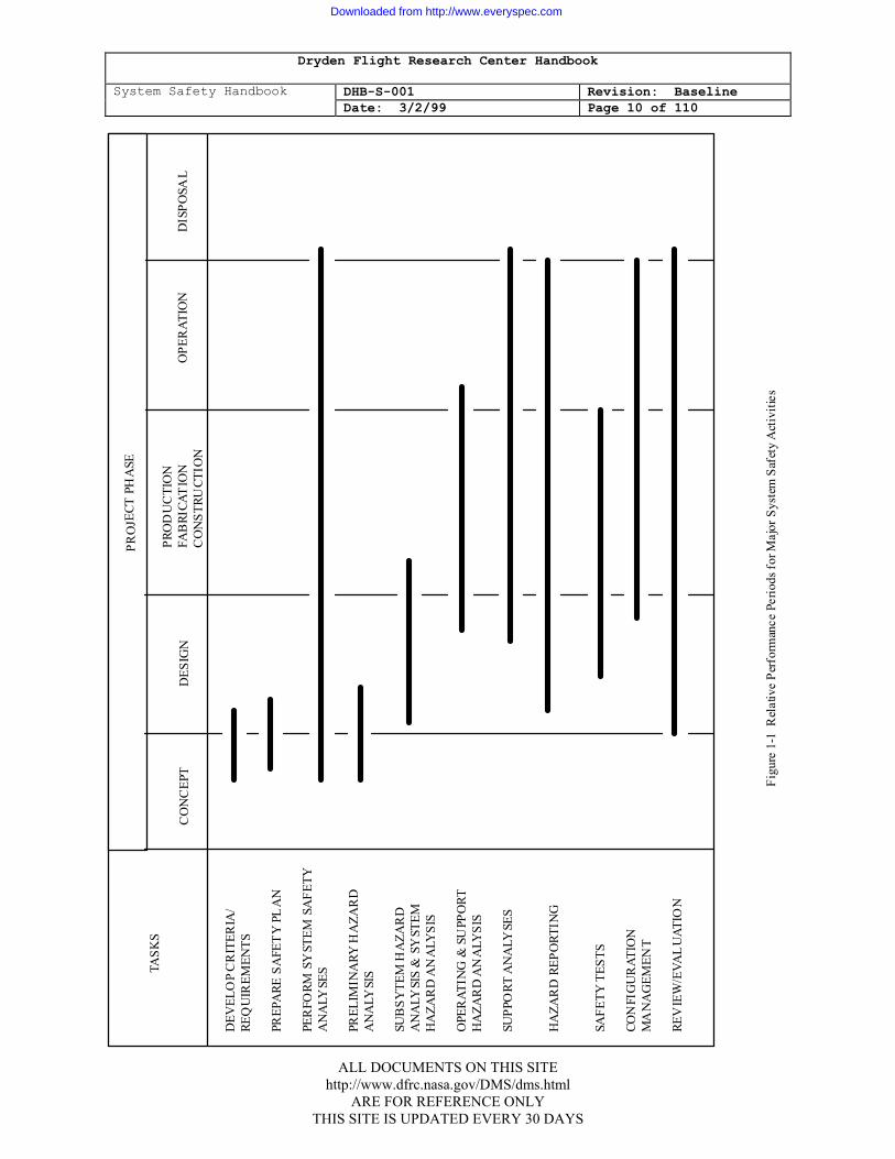
Planning begins as soon as the project is identified and continues throughout the life cycle of the system. (See figure 1-1.) Initial system safety planning includes preparation of the system safety program plan, identification and evaluation of gross hazards, and documentation of technical requirements.
2. ORGANIZING Organization is essential for the timely and effective implementation of the 'system
safety program plan. Responsibility for system safety accountability should be clearly established. Lines of communication should be established for formal reporting. A close relationship should be maintained with all the project elements to accomplish integrated assessments and to assure that system safety continues through the life cycle. Reporting should be to the management level appropriate for risk decision-making.
ALL DOCUMENTS ON THIS SITE http://www.dfrc.nasa.gov/DMS/dms.html
ARE FOR REFERENCE ONLY THIS SITE IS UPDATED EVERY 30 DAYS
Downloaded from http://www.everyspec.com
Dryden Flight Research Center Handbook
System Safety Handbook DHB-S-001 Revision: Baseline Date: 3/2/99 Page 10 of 110
PR
OJE
CT P
HA
SE
TASK
S
PR
OD
UC
TIO
N
CO
NC
EPT
DES
IGN
FAB
RICA
TIO
N
OPE
RAT
ION
D
ISPO
SAL
CO
NST
RUCT
ION
DEV
ELO
P C
RIT
ERIA
/ RE
QU
IREM
ENTS
PR
EPA
RE S
AFE
TY
PLA
N
PER
FORM
SY
STEM
SA
FETY
A
NA
LYSE
S PR
ELIM
INA
RY H
AZA
RD
A
NA
LYSI
S SU
BSY
TEM
HA
ZAR
D
AN
ALY
SIS
& S
YST
EM
HA
ZAR
D A
NA
LYSI
S O
PER
ATIN
G &
SU
PPO
RT
HA
ZAR
D A
NA
LYSI
S SU
PPO
RT A
NA
LYSE
S H
AZA
RD
REP
ORT
ING
SA
FETY
TES
TS
CON
FIG
UR
ATIO
N
MA
NA
GEM
ENT
REV
IEW
/EVA
LU
ATIO
N
Figu
re 1
-1 R
elat
ive
Perf
orm
ance
Per
iods
for M
ajor
Sys
tem
Saf
ety
Act
iviti
es
ALL DOCUMENTS ON THIS SITE
http://www.dfrc.nasa.gov/DMS/dms.html ARE FOR REFERENCE ONLY
THIS SITE IS UPDATED EVERY 30 DAYS
Downloaded from http://www.everyspec.com

Dryden Flight Research Center Handbook
System Safety Handbook DHB-S-001 Revision: Baseline Date: 3/2/99 Page 11 of 110
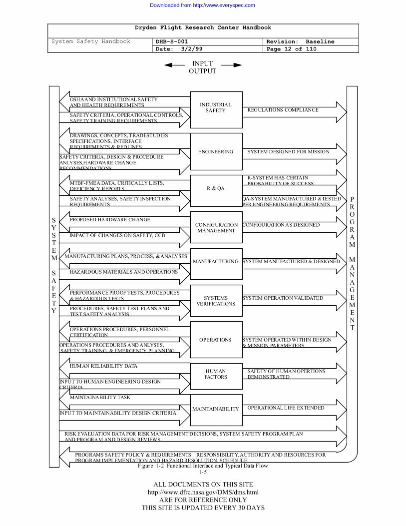
3. COORDINATING The effectiveness of the system safety effort for the project will be greatly
dependent upon the interfaces established with other project elements. Coordination with interfacing organizations should be established at the earliest possible time in project development. As the interfaces are established, the system safety engineer should strive to reach an understanding with all counterparts as to the type and availability of data required for system safety from other organizations and what data and reports will be provided by the system safety engineer. Typical data and information flow is illustrated in figure 1-2.
4. ANALYZING System safety analyses are performed for the purpose of identifying hazards and
providing recommendations for hazard 'elimination or reduction of risk to acceptable levels. These analyses provide the foundation for the development of safety requirements, the mechanism for determining if safety requirements have been fulfilled, and the assurance that recommendations have been implemented.
5. DOCUMENTING The requirement for reporting of progress, hazards, and activities should be
defined in the safety' plan. Reporting covers progress of the effort, milestones attained, and significant accomplishments, such as hazards identified and resolved. Documentation include safety inputs to program reviews relative to the risks being assumed and the status of hazard resolution. Significant data should be identified, filed, and readily retrievable. These data may include requirements, safety study reports, safety analyses, hazard reports, accident/ incident reports, safety audit reports, and safety waiver dispositions.
6. EVALUATING
Periodic evaluation of system safety programs is performed in conjunction with other project tasks and reviews to audit and assess the adequacy of the system safety plan. The review includes surveillance of all system safety aspects, both technical and administrative. The purpose is to ensure:
a. Objectives are being met and the planned tasks are being accomplished on schedule.
b. Adequate data are being provided by safety.
c. Effective use is being made of safety output.
ALL DOCUMENTS ON THIS SITE http://www.dfrc.nasa.gov/DMS/dms.html
ARE FOR REFERENCE ONLY THIS SITE IS UPDATED EVERY 30 DAYS
Downloaded from http://www.everyspec.com
Dryden Flight Research Center Handbook
System Safety Handbook DHB-S-001 Revision: Baseline Date: 3/2/99 Page 12 of 110
S Y S T E M
S A F E T Y
P R O G R A M
M A N A G E M E N T
INPUT OUTPUT
INDUSTRIAL SAFETY
OSHA AND INSTITUTIONAL SAFETY AND HEALTH REQUIREMENTS
SAFETY CRITERIA, OPERATIONAL CONTROLS, SAFETY TRAINING REQUIREMENTS
REGULATIONS COMPLIANCE
ENGINEERING
DRAWINGS, CONCEPTS, TRADESTUDIES SPECIFICATIONS, INTERFACE REQUIREMENTS & REDLINES
SAFETY CRITERIA, DESIGN & PROCEDURE ANLYSES,HARDWARE CHANGE RECOMMENDATIONS
SYSTEM DESIGNED FOR MISSION
R & QAMTBF-FMEA DATA, CRITICALLY LISTS, DEFICIENCY REPORTS
SAFETY ANALYSES, SAFETY INSPECTION REQUIREMENTS
R-SYSTEM HAS CERTAIN PROBABILITY OF SUCCESS
QA-SYSTEM MANUFACTURED &TESTED PER ENGINEERING REQUIREMENTS
CONFIGURATION MANAGEMENT
PROPOSED HARDWARE CHANGE
IMPACT OF CHANGES ON SAFETY, CCB
CONFIGURATION AS DESIGNED
MANUFACTURINGMANUFACTURING PLANS, PROCESS, & ANALYSES
HAZARDOUS MATERIALS AND OPERATIONS
SYSTEM MANUFACTURED & DESIGNED
SYSTEMS VERIFICATIONS
PERFORMANCE PROOF TESTS, PROCEDURES & HAZARDOUS TESTS
PROCEDURES, SAFETY TEST PLANS AND TEST SAFETY ANALYSIS
SYSTEM OPERATION VALIDATED
OPERATIONS
OPERATIONS PROCEDURES, PERSONNEL CERTIFICATION
OPERATIONS PROCEDURES AND ANLYSES, SAFETY TRAINING, & EMERGENCY PLANNING
SYSTEM OPERATED WITHIN DESIGN & MISSION PARAMETERS
HUMAN FACTORS
HUMAN RELIABILITY DATA
INPUT TO HUMAN ENGINEERING DESIGN CRITERIA
SAFETY OF HUMAN OPERTIONS DEMONSTRATED
MAINTAINABILITY
MAINTAINABILITY TASK
INPUT TO MAINTAINABILITY DESIGN CRITERIAOPERATIONAL LIFE EXTENDED
RISK EVALUATION DATA FOR RISK MANAGEMENT DECISIONS, SYSTEM SAFETY PROGRAM PLAN AND PROGRAM AND DESIGN REVIEWS
Figure 1-2 Functional Interface and Typical Data Flow 1-5
PROGRAMS SAFETY POLICY & REQUIREMENTS RESPONSIBILITY, AUTHORITY AND RESOURCES FOR PROGRAM IMPLEMENTATION AND HAZARD RESOLUTION, SCHEDULE
ALL DOCUMENTS ON THIS SITE
http://www.dfrc.nasa.gov/DMS/dms.html ARE FOR REFERENCE ONLY
THIS SITE IS UPDATED EVERY 30 DAYS
Downloaded from http://www.everyspec.com
Dryden Flight Research Center Handbook
System Safety Handbook DHB-S-001 Revision: Baseline Date: 3/2/99 Page 13 of 110
d. Provisions of the system safety plan are adequate. e. Proper documentation of residual risk acceptance decisions. f. Lessons learned are developed and used early to produce effective
system safety input for requirements development. g. An effective hazard tracking system has been implemented by the
managing organization. h. Effective system safety interface with other project management support
function (i.e., human factors, quality assurance, maintenance, logistics, design engineering).
1.7 CONTRACT REQUIREMENTS
Recognizing that portions of the system safety activity may be contracted, it is essential that the SOW describes to the contractor the level of effort and safety tasks required for a particular -program. Although the safety requirements must not be over-specified, each SOW requirement should include the appropriate task objective,. description, and the preferred schedules as they relate to the major project milestones. The method of accomplishing the task will be determined by the contractor. The SOW requirements must be adapted and tailored to the unique needs of the particular project. .(Reference Appendix B.)
ALL DOCUMENTS ON THIS SITE http://www.dfrc.nasa.gov/DMS/dms.html
ARE FOR REFERENCE ONLY THIS SITE IS UPDATED EVERY 30 DAYS
Downloaded from http://www.everyspec.com
Dryden Flight Research Center Handbook
System Safety Handbook DHB-S-001 Revision: Baseline Date: 3/2/99 Page 14 of 110
CHAPTER 2: SYSTEM SAFETY PROGRAM CRITERIA 2.1 SYSTEM SAFETY PROGRAM
The purpose of the system safety program is to assure that a systematic safety management and hazard identification and resolution method is implemented. The project plan will contain a system safety section which will ensure that emphasis is placed on safety during all program phases from concept to disposal.
2.2 SYSTEM SAFETY PLAN
1. The System Safety Plan is considered to be a major element of the Project Plan. It may be issued under separate cover but must be integrated into the Project Plan and must undergo the same approval process as the Project Plan.
2. The purpose of the system safety plan is to provide assurance that program
requirements are understood by each participating organization and to define the tasks, schedule, products, and methods of implementation of the safety program. The preparation of the system safety plan. should be initiated during the concept phase. After completion of the preliminary hazard analysis, the SSPP should be updated to include the specific analyses required and their schedules. This plan should be available at the beginning of the design phase of the project and appropriately updated as the project matures. The content and formality of the system safety plan should be tailored on the basis of project safety criticality, size, and number of organizational interfacing centers involved.
3. The system safety plan will document the project's safety elements and the
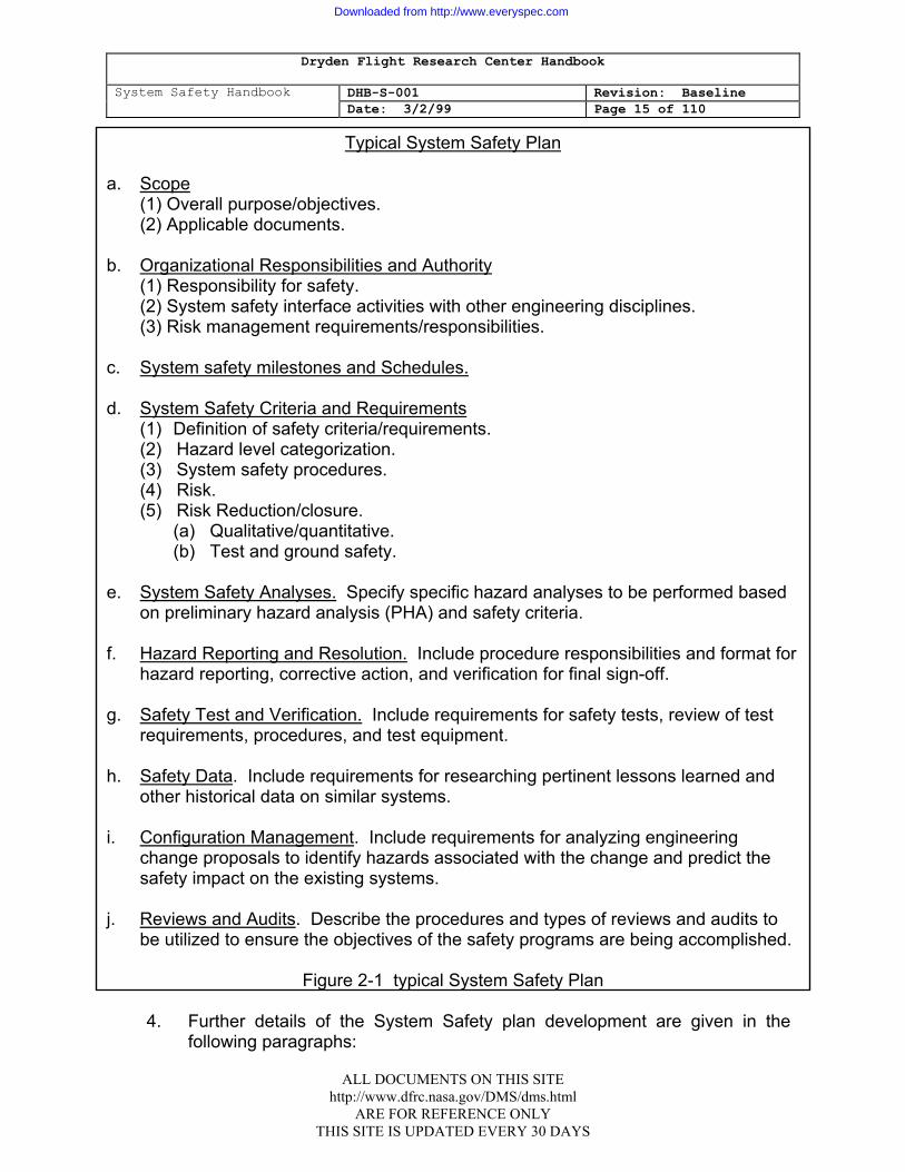
interfaces with other project disciplines. The plan will establish the safety tasks to be performed; the data to be delivered; and the completion schedule during the concept development, requirements definition, design, manufacture, test, operations, handling, transportation, and disposal phases of the project. Assignment of responsibilities, reporting procedures, and data to be 'exchanged will be delineated. See figure 2-1 for typical contents of a system safety plan.
ALL DOCUMENTS ON THIS SITE http://www.dfrc.nasa.gov/DMS/dms.html
ARE FOR REFERENCE ONLY THIS SITE IS UPDATED EVERY 30 DAYS
Downloaded from http://www.everyspec.com
Dryden Flight Research Center Handbook
System Safety Handbook DHB-S-001 Revision: Baseline Date: 3/2/99 Page 15 of 110
Typical System Safety Plan
a. Scope (1) Overall purpose/objectives. (2) Applicable documents. b. Organizational Responsibilities and Authority (1) Responsibility for safety. (2) System safety interface activities with other engineering disciplines. (3) Risk management requirements/responsibilities. c. System safety milestones and Schedules. d. System Safety Criteria and Requirements
(1) Definition of safety criteria/requirements. (2) Hazard level categorization. (3) System safety procedures. (4) Risk. (5) Risk Reduction/closure.
(a) Qualitative/quantitative. (b) Test and ground safety.
e. System Safety Analyses. Specify specific hazard analyses to be performed based
on preliminary hazard analysis (PHA) and safety criteria. f. Hazard Reporting and Resolution. Include procedure responsibilities and format for
hazard reporting, corrective action, and verification for final sign-off. g. Safety Test and Verification. Include requirements for safety tests, review of test
requirements, procedures, and test equipment. h. Safety Data. Include requirements for researching pertinent lessons learned and
other historical data on similar systems. i. Configuration Management. Include requirements for analyzing engineering
change proposals to identify hazards associated with the change and predict the safety impact on the existing systems.
j. Reviews and Audits. Describe the procedures and types of reviews and audits to
be utilized to ensure the objectives of the safety programs are being accomplished.
Figure 2-1 typical System Safety Plan 4. Further details of the System Safety plan development are given in the
following paragraphs:
ALL DOCUMENTS ON THIS SITE http://www.dfrc.nasa.gov/DMS/dms.html
ARE FOR REFERENCE ONLY THIS SITE IS UPDATED EVERY 30 DAYS
Downloaded from http://www.everyspec.com
Dryden Flight Research Center Handbook
System Safety Handbook DHB-S-001 Revision: Baseline Date: 3/2/99 Page 16 of 110
Purpose
The project System Safety Plan sets forth the areas of concern and risk that the project must concentrate its attention upon in order to obtain its objectives in the most efficient manner consistent with safe operating practices. The plan will detail what safety analyses will be performed and which milestones they will support. It will also detail which and what level of resources will be required to perform these analyses, i.e. in-house personnel, on-site contractors, project off-site contractors, etc.
The approved System Safety Plan should be viewed as a signed contract between upper management and project management.
Responsibilities
The responsibility for the writing and implementation of the System Safety Plan are clearly assigned to the Project Manager. However, because of the matrix management system at Ames-Dryden, each functional element at this Facility has a responsibility to assist the Project Manager in the determination of analysis requirements, analysis adequacy, and required risk assessment and resolution in areas that fall under their normal functional responsibility . Therefore, each functional element with a project responsibility will take part in the system safety process, with the Project Manager actually coordinating and ensuring the continuing process for his/her project.
Minimum Analysis
While it is recognized and highlighted that the NASA System Safety Handbook is written in guideline language and that no project is expected to perform all, available analyses, some are usually considered essential to the proper conduct of a project. These include:
A. Preliminary Hazard Analysis (PHA) - Conducted -in the very earliest
stages of a project, this analysis is used to support initial project approval and the Preliminary Design Review.
B. Subsystem Hazard Analysis (SSHA) - Any newly designed, or highly
modified, vehicle control system or major experiment that changes the functional configuration, would call for an SSHA to be performed. If this analysis is performed, an analysis of the interface between the subsystem or experiment and the vehicle must be included. These analyses must be available to support the Critical Design Review and updated to support the Flight Readiness Review.
ALL DOCUMENTS ON THIS SITE http://www.dfrc.nasa.gov/DMS/dms.html
ARE FOR REFERENCE ONLY THIS SITE IS UPDATED EVERY 30 DAYS
Downloaded from http://www.everyspec.com
Dryden Flight Research Center Handbook
System Safety Handbook DHB-S-001 Revision: Baseline Date: 3/2/99 Page 17 of 110
C. Operational Hazard Analysis (OHA) - This is normally required to support
the AFFTC Safety Review and our own Flight Readiness Review. 2.3 SYSTEM SAFETY REQUIREMENTS
1. Requirements should be established on the basis of (1) the identification of gross hazards during the conceptual phase, (2) requirements from experience gained on similar projects, and (3) pertinent standards, specifications, regulations, and design handbooks. See Appendix C for list of applicable documents. As an example, design criteria for pressure systems are contained in:
a. NSS/HP-1740.1 - NASA Aerospace Pressure Vessel Safety
Standard. b. MIL-STD-1522 - Standard General Requirement for Safe Design and Operation of Pressurized Missile and Space Systems. c. ASME Boiler and Pressure Vessel Code, Section VIII, Divisions I and II.
Similarly, other consensus standards or Agency design criteria documents stipulate basic requirements and should be used to develop criteria for other systems or system elements.
The system safety engineer must evaluate project requirements and system complexity to define safety requirements. Based on engineering experience gained on other similar projects, the system safety engineer can deduce safety requirements by consideration of the general personnel/ equipment interfaces, subsystem/ system interfaces, environmental constraints, and the type of equipment (electrical, mechanical, high energy) involved. Consideration should also be given to materials selection, fabrication, operations, maintenance, testing, storage, handling, transportation, and disposal.
3. Safety requirements should be integrated into the system design requirements documentation and coordinated with the design function. In addition, a special safety requirements document may be required on more complex systems to provide a controlled methodical means of tracking to ensure all safety requirements are addressed. The requirements document may also be used to develop specification and contract requirements. Requests for exemption from safety requirements should be a formal process with full documentation of the circumstances of its issuance and management concurrence.
ALL DOCUMENTS ON THIS SITE http://www.dfrc.nasa.gov/DMS/dms.html
ARE FOR REFERENCE ONLY THIS SITE IS UPDATED EVERY 30 DAYS
Downloaded from http://www.everyspec.com
Dryden Flight Research Center Handbook
System Safety Handbook DHB-S-001 Revision: Baseline Date: 3/2/99 Page 18 of 110
2.4 SYSTEM SAFETY ANALYSES
The purpose of system safety analyses is to identify hazards and provide the mechanism for their disposal. It is an iterative process that begins in the concept phase and extends through the operational phase. The initial assessment, the preliminary hazard analysis (PHA), documents the gross hazards generally associated with assessment of the design and operational concept, and provides the framework for a master catalog of hazards and associated risks. As the design and operations are defined during subsequent life-cycle phases, the hazard catalog is updated to reflect results of more detailed hazard analyses. Analyses, such as subsystem/ system hazard analysis (S/SHA) and-operating and support hazard analysis (O&SHA), will be employed to the. extent and depth necessary to assure minimization of threat to personnel or damage to equipment and property. Analyses and techniques available to the system safety engineer are discussed in detail in Chapter 3.0 and Appendix D.
2.5 RISK MANAGEMENT
The purpose of risk management is to assure that (1) hazards are identified and evaluated in a timely manner, (2) the risks are assessed, acceptable, and consistent with the complexity of the system, and (3) the aggregate risk is recognized and accepted by project management.
1. RISK IDENTIFICATION
Hazards associated with each project will be identified, documented, and reviewed periodically to assure risk visibility.
2. RISK ASSESSMENT,
Risk assessment is a continuing process throughout the life cycle of a project, but formal risk acceptance must be performed prior to initial system operation and all significant project activities. Decisions regarding resolution of identified hazards will be based on assessment of the risk involved. To aid in the achievement of the objectives of system safety, hazards will be characterized as to severity and probability. Since the priority for system safety is to eliminate hazards by design, a risk assessment procedure considering only severity will generally suffice during the early design phase. When hazards are not eliminated during the early design phase, a risk assessment procedure based upon the probability, as well as severity, will be used to establish priorities for corrective action and resolution. Quantitative analysis will be performed only where the risks of parts/components failures and human errors for the operational environment are known with, reasonable confidence and the criticality. of alternative designs is sufficiently important to safety. The
ALL DOCUMENTS ON THIS SITE http://www.dfrc.nasa.gov/DMS/dms.html
ARE FOR REFERENCE ONLY THIS SITE IS UPDATED EVERY 30 DAYS
Downloaded from http://www.everyspec.com
Dryden Flight Research Center Handbook
System Safety Handbook DHB-S-001 Revision: Baseline Date: 3/2/99 Page 19 of 110
risk, assessment criteria approach discussed in Appendix E may be used as a guide. After all risk avoidance measures have been identified and studied, and after technical rationale for risk acceptance has been documented, the risks will be presented to the appropriate level of management for approval.
3. RISK REDUCTION The purpose of risk reduction criteria is to provide a consistent and systematic
method for assuring that the risks associated with identified hazards are minimized. Risk closure criteria are established to assure risks are evaluated and closed uniformly. Hazardous conditions, causes, effects, control (or acceptance rationale), verification, results, and status are identified and documented as a product of the hazard analyses. It is the system safety engineer's responsibility to prepare and evaluate these analyses to assure that the requirements are being met and that risks associated with the hazards are reduced to the maximum practical extent. As the design progresses, actions for reducing. the risks will be undertaken in the following order of precedence:
a. Design to eliminate the hazard or hazardous operation. b. Reduce risks to an acceptable level through the use of fixed, automatic,
or other protective design features or devices. c. Provide detection and warning/caution devices. d. Develop procedures and training including protective equipment for
personnel. A lesser degree of safety desirability exists for each succeeding control method. If a risk reduction method other than elimination of the hazard source or hazardous operation is selected, a certain level of risk must be assumed by the project manager. The acceptability of hazard controls should be based on the nature of the risks and the options available to achieve the maximum benefit.
4. APPROVAL OF RISKS
Each risk will be evaluated, documented, and accepted by project management. Accepted risks will be reviewed periodically to take advantage of new technology, concepts, and conditions which may permit hazard elimination or control. The review process and documentation requirements may vary from project to project; however, all accepted risks must be documented and approved by the appropriate NASA management level as defined in the project plan. The flow of safety data from identification of
ALL DOCUMENTS ON THIS SITE http://www.dfrc.nasa.gov/DMS/dms.html
ARE FOR REFERENCE ONLY THIS SITE IS UPDATED EVERY 30 DAYS
Downloaded from http://www.everyspec.com
Dryden Flight Research Center Handbook
System Safety Handbook DHB-S-001 Revision: Baseline Date: 3/2/99 Page 20 of 110
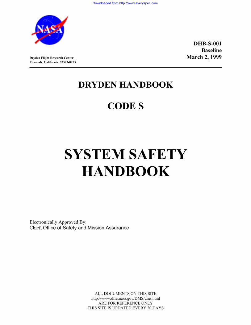
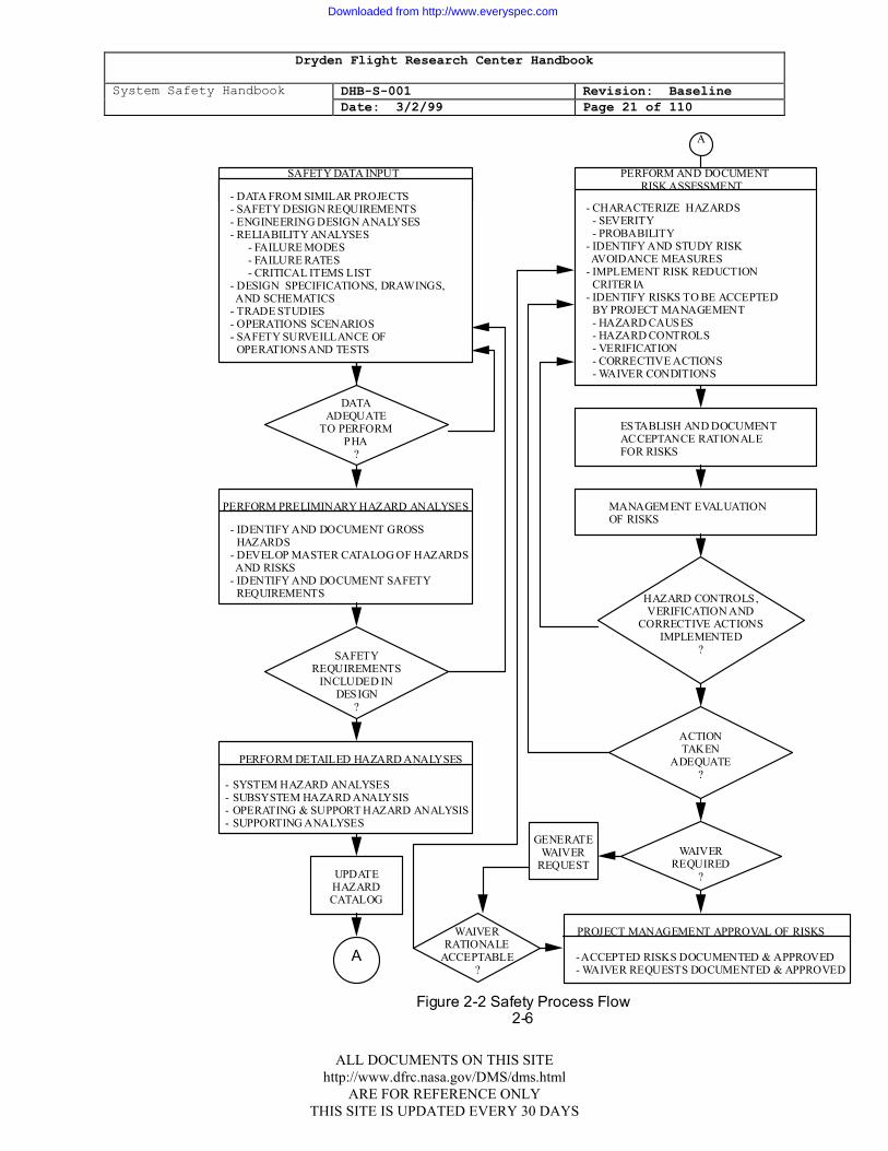
hazard,. through generation of controls, and hence to review and approval by project management, is illustrated in figure 2-2.
2.6 SAFETY VERIFICATION
The purpose of safety verification is to establish the validity of the hazard analyses and verify the system meets safety and-operational requirements. System safety management procedures for accomplishing this are effected by various reviews and system tests which provide independent technical assessment.
1. ANALYSES VERIFICATION
The technical assessment involves an independent review and evaluation of the hazard analyses results.. Verification should be performed on. a continuing basis by evaluating hazard analyses results performed for informal and formal design reviews. Further technical assessment of contractor hazard analyses should be performed by project system safety engineering with formal approval of the deliverable data. In verifying an analysis involving a serious (catastrophic or critical) hazardous condition, risk assessment techniques should be used.
2. TEST VERIFICATION
Test plans, specifications,. procedures, and results are reviewed by the project system safety engineer to confirm that the system will meet safety design and operational requirements. Monitoring and evaluation of the test program facilitate a cost-effective approach to the safety verification method. In turn, the project system safety engineer assists the test activity in identifying unique hazards and safety requirements required to minimize the risks.
ALL DOCUMENTS ON THIS SITE http://www.dfrc.nasa.gov/DMS/dms.html
ARE FOR REFERENCE ONLY THIS SITE IS UPDATED EVERY 30 DAYS
Downloaded from http://www.everyspec.com
Dryden Flight Research Center Handbook
System Safety Handbook DHB-S-001 Revision: Baseline Date: 3/2/99 Page 21 of 110
SAFETY DATA INPUT
- DATA FROM SIMILAR PROJECTS - SAFETY DESIGN REQUIREMENTS - ENGINEERING DESIGN ANALYSES - RELIABILITY ANALYSES - FAILURE MODES - FAILURE RATES - CRITICAL ITEMS LIST - DESIGN SPECIFICATIONS, DRAWINGS, AND SCHEMATICS - TRADE STUDIES - OPERATIONS SCENARIOS - SAFETY SURVEILLANCE OF OPERATIONS AND TESTS
- CHARACTERIZE HAZARDS - SEVERITY - PROBABILITY - IDENTIFY AND STUDY RISK AVOIDANCE MEASURES - IMPLEMENT RISK REDUCTION CRITERIA - IDENTIFY RISKS TO BE ACCEPTED BY PROJECT MANAGEMENT - HAZARD CAUSES - HAZARD CONTROLS - VERIFICATION - CORRECTIVE ACTIONS - WAIVER CONDITIONS
ESTABLISH AND DOCUMENT ACCEPTANCE RATIONALE FOR RISKS
PERFORM AND DOCUMENT RISK ASSESSMENT
MANAGEMENT EVALUATION OF RISKS
A
DATA ADEQUATE
TO PERFORM PHA
?
PERFORM PRELIMINARY HAZARD ANALYSES
- IDENTIFY AND DOCUMENT GROSS HAZARDS - DEVELOP MASTER CATALOG OF HAZARDS AND RISKS - IDENTIFY AND DOCUMENT SAFETY REQUIREMENTS
SAFETY REQUIREMENTS
INCLUDED IN DESIGN
?
PERFORM DETAILED HAZARD ANALYSES
- SYSTEM HAZARD ANALYSES - SUBSYSTEM HAZARD ANALYSIS - OPERATING & SUPPORT HAZARD ANALYSIS - SUPPORTING ANALYSES
Figure 2-2 Safety Process Flow 2-6
UPDATE HAZARD CATALOG
A
HAZARD CONTROLS, VERIFICATION AND
CORRECTIVE ACTIONS IMPLEMENTED
?
ACTION TAKEN
ADEQUATE ?
WAIVER REQUIRED
?
PROJECT MANAGEMENT APPROVAL OF RISKS
- ACCEPTED RISKS DOCUMENTED & APPROVED - WAIVER REQUESTS DOCUMENTED & APPROVED
GENERATE WAIVER
REQUEST
WAIVER RATIONALE
ACCEPTABLE ?
ALL DOCUMENTS ON THIS SITE http://www.dfrc.nasa.gov/DMS/dms.html
ARE FOR REFERENCE ONLY THIS SITE IS UPDATED EVERY 30 DAYS
Downloaded from http://www.everyspec.com
Dryden Flight Research Center Handbook
System Safety Handbook DHB-S-001 Revision: Baseline Date: 3/2/99 Page 22 of 110
a. Performance Proof Tests
Overall performance testing is monitored to verify that the system meets safety and operational requirements as demonstrated by the performance proof test program.
b. Special Safety Tests
Special safety tests may be required of critical components to demonstrate that safety margins and workmanship are adequate.
c. Safety Systems Tests
Functional testing of safety systems may be required to assure that hazardous conditions can be adequately controlled by the prescribed design, safety devices, and warning/caution devices.
3. HAZARD CLOSURE VERIFICATION
The system safety engineer will implement a procedure to ensure that the corrective actions defined for hazard closure have been successfully implemented, such as in design documentation, test plans, test reports, and operations and maintenance procedures. The acceptance of closure methodology and rationale will be formally documented and presented at the appropriate project reviews.
2.7 PROJECT REVIEW REQUIREMENTS
1. SYSTEM SAFETY PROGRAM MILESTONES
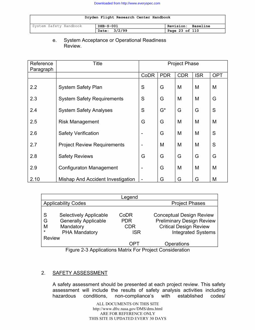
System safety program milestones will be integrated with the overall project milestones and reviews to assure that management has the safety information required to assist them in their decision-making. See figure 2-3. The purpose of safety participation in project reviews is to assure safety requirements have been imposed and implemented, and adequate verification methods have been established. Typical project reviews include, but are not limited to:
a. Conceptual Design Review. b. Preliminary Design Review. c. Critical Design Review. d. Integrated Systems Review.
ALL DOCUMENTS ON THIS SITE http://www.dfrc.nasa.gov/DMS/dms.html
ARE FOR REFERENCE ONLY THIS SITE IS UPDATED EVERY 30 DAYS
Downloaded from http://www.everyspec.com
Dryden Flight Research Center Handbook
System Safety Handbook DHB-S-001 Revision: Baseline Date: 3/2/99 Page 23 of 110
e. System Acceptance or Operational Readiness
Review.
Reference Paragraph
Title
Project Phase
CoDR PDR CDR ISR OPT 2.2 2.3 2.4 2.5 2.6 2.7 2.8 2.9 2.10
System Safety Plan System Safety Requirements System Safety Analyses Risk Management Safety Verification Project Review Requirements Safety Reviews Configuraton Management Mishap And Accident Investigation
S S S G - - G - -
G G G* G G M G G G
M M G M M M G M G
M M G M M M G M G
M G S M S S G M M
Legend Applicability Codes Project Phases S Selectively Applicable CoDR Conceptual Design Review G Generally Applicable PDR Preliminary Design ReviewM Mandatory CDR Critical Design Review * PHA Mandatory ISR Integrated Systems Review OPT Operations
Figure 2-3 Applications Matrix For Project Consideration
2. SAFETY ASSESSMENT
A safety assessment should be presented at each project review. This safety assessment will include the results of safety analysis activities including hazardous conditions, non-compliance’s with established codes/
ALL DOCUMENTS ON THIS SITE http://www.dfrc.nasa.gov/DMS/dms.html
ARE FOR REFERENCE ONLY THIS SITE IS UPDATED EVERY 30 DAYS
Downloaded from http://www.everyspec.com
Dryden Flight Research Center Handbook
System Safety Handbook DHB-S-001 Revision: Baseline Date: 3/2/99 Page 24 of 110
regulations/requirements, causes, effects, controls, safety verification methods, and risk acceptance rationale. All open safety work and action items should be documented and submitted with the final assessment. for management action.
a. Conceptual Design Review
A hazard analysis should be performed prior to the conceptual design review to assure that appropriate safety requirements will be identified.
b. Preliminary Design Review A preliminary hazard analysis will be prepared to determine areas requiring special safety studies. Subsystem and system level hazard analyses may be performed to identify hazards and to assure that the safety requirements have been addressed in the design. A hazard tracking system will be implemented.
c. Critical Design Review
The review should include the hazard analyses results necessary to assure that the design can meet the safety requirements.
d. Integrated Systems Review
This review is normally held prior to systems level tests and integrates all the elements of a program. A safety assessment utilizing the results of all previously performed safety analyses should be provided. Each hazard control will be identified at this review.
e. Systems Acceptance Review/Operational Readiness Review The systems acceptance review, or operational readiness review will
include an overall safety assessment considering all aspects of equipment, facilities, personnel, and operations. Assurance should be provided that all safety analyses have been completed and that hazards have been identified, evaluated, and accepted by the appropriate level of management.
2.8 SAFETY REVIEWS
In the life cycle of a project, it is advisable to conduct periodic safety reviews to assess progress and implementation of safety program requirements, provide for interchange of information, and to evaluate the results of the safety effort. The necessity for such reviews is a function of project complexity and safety criticality.
ALL DOCUMENTS ON THIS SITE http://www.dfrc.nasa.gov/DMS/dms.html
ARE FOR REFERENCE ONLY THIS SITE IS UPDATED EVERY 30 DAYS
Downloaded from http://www.everyspec.com
Dryden Flight Research Center Handbook
System Safety Handbook DHB-S-001 Revision: Baseline Date: 3/2/99 Page 25 of 110
Such reviews are a mechanism to assure Timely identification and tracking of hazards. Specific objectives of the reviews should include evaluation of the adequacy of, safety program guidelines, constraints, and project requirements. These reviews should be conducted by an independent panel of senior engineers and operations management personnel exclusive of project . management. Review panel membership should be structured to assure that appropriate technical specialists knowledgeable of the systems under review are represented; but membership should also be tailored to ensure a continuity of project direction and implementation. Results of such special reviews should be documented with open items tracked to closure, and such results should be reported at the major project reviews for final management approval .
2.9 CONFIGURATION MANAGEMENT
The purpose of system safety involvement in configuration management is to maintain an understanding of the baseline configuration and any subsequent changes. This will allow hazard identification activities to be performed on the latest configuration. All requirements,
hardware, software, and procedural changes from the established baseline should be evaluated for safety impact. Change proposals and requests should be reviewed by the system safety engineer, and recommendations for change acceptance, rejection, or modification provided to the appropriate configuration control board. Hazard analyses and hazard lists should be updated, as required, to reflect hazards that have been introduced, eliminated, or modified as the result of a configuration change. The degree of formality of change controls and participation in configuration control boards may be tailored consistent with the project criticality, size, and number of organizations involved.
2.10 MISHAP AND ACCIDENT INVESTIGATION
Mishap and accident investigation and reporting are accomplished and tailored in accordance With NPD 8700.1. System safety participation normally includes:
1. Safety analyses preparation in support of the investigation board. 2. "Lessons Learned" generation and documentation for inclusion in the NASA
mishap report files in the NASA Recon System.
ALL DOCUMENTS ON THIS SITE http://www.dfrc.nasa.gov/DMS/dms.html
ARE FOR REFERENCE ONLY THIS SITE IS UPDATED EVERY 30 DAYS
Downloaded from http://www.everyspec.com
Dryden Flight Research Center Handbook
System Safety Handbook DHB-S-001 Revision: Baseline Date: 3/2/99 Page 26 of 110
CHAPTER 3: SYSTEM SAFETY ANALYSES 3.1 INTRODUCTION
This section presents a description of the three common system safety analyses used to satisfy project requirements. These analyses are the, preliminary hazard analysis', the subsystem hazard analysis and system hazard analysis, and the operating and support hazard analysis. Each analysis section includes the purpose, description, and project phase which is suggested for application of the particular analysis (Reference Appendix D).
3.2 PRELIMINARY HAZARD ANALYSIS (PHA)
1. PURPOSE
The purpose of the PHA is to identify safety-critical areas, evaluate hazards, and identify the safety design criteria to be used in the project . It also provides management with knowledge of potential risks during feasibility studies and project definition activities.
2. DESCRIPTION
The PHA is performed to document an initial risk assessment of a concept or system. Based on the best available data, including pertinent safety experience from similar systems and other lessons learned, hazards associated with the. proposed design or function will be evaluated for potential severity, probability, and operational constraints. Design control and alternatives needed to eliminate hazards or reduce their associated risk 'to an acceptable level should be considered. The PHA provides consideration of the following for identification and evaluation of hazards.
a. Hazardous components (e.g., fuels, propellants, lasers, explosives, toxic
substances, hazardous construction materials, pressure systems, radiation sources, and other energy sources).
b . Safety-related interface considerations among various elements of the
system (e.g., material compatibilities, electromagnetic interference, inadvertent activation, fire/explosion initiation and propagation, electrostatic susceptibility, and hardware and software controls).
c. Environmental constraints including the operating. environment; (e.g., drop shock, vibration, extreme temperatures asphyxiates noise, exposure to toxic substances, fire, electrostatic discharge, oxygen deficiency and/or hazardous atmosphere, lightning, electromagnetic environmental effects, and ionizing and non-ionizing radiation).
ALL DOCUMENTS ON THIS SITE http://www.dfrc.nasa.gov/DMS/dms.html
ARE FOR REFERENCE ONLY THIS SITE IS UPDATED EVERY 30 DAYS
Downloaded from http://www.everyspec.com
Dryden Flight Research Center Handbook
System Safety Handbook DHB-S-001 Revision: Baseline Date: 3/2/99 Page 27 of 110
d. Operating, test, maintenance, emergency, and contingency procedures
(e.g., human error analysis of operator functions, tasks, and requirements; effects of factors such as equipment layout and lighting requirements; effects of noise or radiation on human performance; life support requirements and their safety implications in manned systems, crash safety, egress, rescue, survival, and salvage).
e. Facilities, support equipment (e.g., provisions for storage, assembly,
checkout, proof-testing of hazardous systems/ assemblies which may include toxic, flammable, explosive, corrosive or cryogenic fluids; radiation or noise emitters; electrical power sources) and training, (e.g., training and certification pertaining to safety operations and maintenance).
f. Safety related equipment, safeguards, and possible alternative
approaches (e.g., interlocks, system redundancy, hardware or software fail-safe design considerations, subsystem. protection, fire suppression systems, personal protective equipment, ventilation, and noise or radiation barriers).
g. Identification of and compliance with pertinent regulations and
standards.
3. PROJECT PHASE
The PHA effort should be initiated during the concept phase of a project so that safety Considerations are included in trade-studies and design alternatives .
4. PHA TECHNIQUE
A recommended format discussion is contained in Appendix D.
3.3 SUBSYSTEM HAZARD ANALYSIS (SSHA) AND SYSTEM HAZARD
ANALYSIS (SHA)
1. PURPOSE
The purpose of an SSHA is to identify hazards associated with design of subsystems including component failure modes, critical human error inputs, and hazards resulting from functional relationships between components and
ALL DOCUMENTS ON THIS SITE http://www.dfrc.nasa.gov/DMS/dms.html
ARE FOR REFERENCE ONLY THIS SITE IS UPDATED EVERY 30 DAYS
Downloaded from http://www.everyspec.com
Dryden Flight Research Center Handbook
System Safety Handbook DHB-S-001 Revision: Baseline Date: 3/2/99 Page 28 of 110
equipment comprising each subsystem. The purpose of an SHA is to determine the safety problem areas of the total system design, including interfaces, and potential safety-critical human error.
2. DESCRIPTION
The SSHA identifies and documents all components and equipment, including software, whose performance, performance degradation, functional failure, or inadvertent functioning could result in a hazard. The analysis includes a determination of the modes of failure including credible human errors as well as single failure points and the effects on safety when failures occur in subsystem components. The SHA identifies and documents hazards, and assesses the he risk of the total system design including the subsystem interfaces This analysis includes a review of subsystem interrelationships for: a. Compliance with specified safety requirements.
b . Possible independent, dependent, and simultaneous credible. hazardous
events, including failures of safety devices and common causes that could create a hazard.
c. Degradation in the safety of a subsystem or the total system from normal
operation of another system. d. Design changes.
e. Effects of credible human errors.
3. PROJECT PHASE
The SSHA effort should begin as the preliminary design and concept definition are established and progress through the detailed design of components, equipment, and software. The SSHA will be updated when needed as a result of any subsystem design changes. The SHA effort will begin as system and subsystem design and interfaces, including software, are defined. The SHA will be upgraded when needed as a result of system design and interface changes.
4. TECHNIQUE
The fault hazard analysis (FHA) is the inductive system analysis most commonly used for subsystem and system hazard analysis. See Appendix D.
ALL DOCUMENTS ON THIS SITE http://www.dfrc.nasa.gov/DMS/dms.html
ARE FOR REFERENCE ONLY THIS SITE IS UPDATED EVERY 30 DAYS
Downloaded from http://www.everyspec.com
Dryden Flight Research Center Handbook
System Safety Handbook DHB-S-001 Revision: Baseline Date: 3/2/99 Page 29 of 110
3.4 OPERATING AND SUPPORT HAZARD ANALYSIS (O&SHA)
1. PURPOSE
The O&SHA is performed to identify and evaluate hazards associated with personnel, procedures, environment, and the equipment involved throughout the operation and maintenance of the system during all phases of intended use.
2. DESCRIPTION
The O&SHA is performed to examine procedurally controlled activities. It identifies and evaluates hazards resulting from the implementation of operations or tasks performed by persons and should consider the planned system configuration at each phase of activity; the facility interfaces; the planned environments, the supporting tools, or other equipment specified for use; operation or task sequence, concurrent task effects, and limitations; biotechnological factors;. regulatory or contractually specified personnel safety and health requirements; and the potential for unplanned events including hazards introduced by human error. The O&SHA identifies the safety requirements (or alternatives) needed to eliminate identified hazards, or to reduce the associated risk to a level which is acceptable. The analysis should identify:
a. Activities which occur under hazardous conditions, their time periods,
and the actions required to minimize risk during the activities and time periods.
b. Changes needed in hardware and software, facilities, tooling, or
support/test equipment to eliminate hazards or reduce associated risks .
c. Requirements for safety devices and equipment, including personnel safety and life-support equipment.
d. Requirements for warnings, cautions, and special emergency
procedures (e.g., egress, rescue, escape, render-safe, backout, etc.). e. Requirements for handling, storage, transportation, maintenance, and
disposal of hazardous materials. f. Requirements for safety training and personnel certification.
ALL DOCUMENTS ON THIS SITE http://www.dfrc.nasa.gov/DMS/dms.html
ARE FOR REFERENCE ONLY THIS SITE IS UPDATED EVERY 30 DAYS
Downloaded from http://www.everyspec.com
Dryden Flight Research Center Handbook
System Safety Handbook DHB-S-001 Revision: Baseline Date: 3/2/99 Page 30 of 110
The O&SHA documents the system safety assessment of procedures involved in production, assembly, test, operation, maintenance, servicing, transportation, storage, modification, and disposal.
3. PROJECT PHASE
The O&SHA effort should begin when operational concepts are developed. The O&SHA development process is a continuing effort that parallels the manufacturing process and the 6 subsequent development of operational and maintenance procedures. The analysis is usually completed after all procedures have been written and validated. The O&SHA will be updated, when needed, as a result of any system, design, procedures, or operational change.
4. O&SHA TECHNIQUE
An O&SHA columnar Iumnar format discussion is contained in Appendix D. This format is designed with the intent of establishing a systematic method whereby operations are broken down into incremental parts and consistently analyzed for hazards. The O&SHA form should not necessarily be held rigid, but modified to the specific needs of the user. O&SHA hazards can be recognized through checklists by comparing the configuration of the operations under analysis (hardware, tasks sequence, tools, environment, etc.) against the hazardous elements and hazardous conditions on the checklists. Operational elements which correlate with items on the checklist indicate a possible hazard or a possible safety critical area.
ALL DOCUMENTS ON THIS SITE http://www.dfrc.nasa.gov/DMS/dms.html
ARE FOR REFERENCE ONLY THIS SITE IS UPDATED EVERY 30 DAYS
Downloaded from http://www.everyspec.com
Dryden Flight Research Center Handbook
System Safety Handbook DHB-S-001 Revision: Baseline Date: 3/2/99 Page 31 of 110
APPENDIX A: DEFINITIONS
Loss Hazard General hazard that is identified during the preliminary hazard
analysis process. Hazard The presence of a potential risk situation caused by on unsafe
act or condition. Hazard Analysis The determination of potential sources of danger and
recommended resolutions in a timely manner for those conditions found in either the hardware software systems, the person-machine relationship, or both, which cause loss of personnel capability, loss of system, or loss of life or injury to the public.
Risk The chance (qualitative) of loss of personnel capability, loss of
system, or damage to or loss of equipment or property. Safety Freedom from chance of injury or loss of personnel, equipment, or
property. Safety Critical Facility, support, test, and flight systems containing:
a. Pressurized vessels, lines, and components. b. Propellants, including cryogenics. c. Hydraulic and
pneumatics. d. High voltages. e. Radiation sources. f. Ordnance and explosive devices or devices used for ordnance
and explosive checkout. g. Flammable, toxic cryogenic, or reactive elements or
compounds. h. High
temperatures. i. Electrical equipment that operates in the area where flammable
fluids or solids are located. j. Equipment used for handling program hardware. k. Equipment used for personnel walking and work platforms.. l. Electrostatic susceptible devices.
ALL DOCUMENTS ON THIS SITE http://www.dfrc.nasa.gov/DMS/dms.html
ARE FOR REFERENCE ONLY THIS SITE IS UPDATED EVERY 30 DAYS
Downloaded from http://www.everyspec.com
Dryden Flight Research Center Handbook
System Safety Handbook DHB-S-001 Revision: Baseline Date: 3/2/99 Page 32 of 110
System Safety The optimum degree of risk management within the constraints of operational effectiveness, time, and cost attained through the application of management and engineering principles throughout all phases of a program. Waiver Granted use or acceptance of an article which does not meet the specified requirements, criteria, or standards.
ALL DOCUMENTS ON THIS SITE http://www.dfrc.nasa.gov/DMS/dms.html
ARE FOR REFERENCE ONLY THIS SITE IS UPDATED EVERY 30 DAYS
Downloaded from http://www.everyspec.com
Dryden Flight Research Center Handbook
System Safety Handbook DHB-S-001 Revision: Baseline Date: 3/2/99 Page 33 of 110
APPENDIX B: SYSTEM SAFETY PROCUREMENT
GUIDELINES 1.1 POLICY
1. System safety is a factor which must be considered in each step of program
development, project planning., and the procurement process. The appropriate technical application of NASA safety publications and the inclusion of realistic requirements in procurement are essential to accomplish NASA mission objectives. Those ultimately responsible for the content and quality of requests for proposals will ensure that system safety requirements are treated prudently in the proposal preparation and negotiation process.
2. System safety requirements will be established as early as possible in the
procurement cycle and will be made a part of the procurement request. The safety criteria and requirements for flight and flight related hardware, including ground support equipment and special facilities, will be directly related to the project, hardware, the stage of development, and procurement situation. The system safety requirements normally will be referenced is a subdivision of work or a task in the SOW and detailed in an Appendix to the SOW. When structuring such document, care should be taken to ensure that there is no duplication of requirements and a minimum of overlap between the areas of quality assurance, reliability assurance, and system safety.
3. System safety documentation will be phased into the proposal preparation and
negotiation process in such a manner that the degree of detail required in the proposal is commensurate with the intended use of the system safety program as a factor or criterion in evaluating the overall proposal. In general, the greater the emphasis on the use of the contractor's program and procedures, the greater will be the degree of detail appropriate in the proposal. However, regardless of the degree of detail. required for the initial system safety plan, it is also necessary for evaluation purposes in major negotiated procurements, including those conducted on a noncompetitive basis, and that initial cost pro-posals include an estimate of man-hours and other costs associated with each major safety task area defined in' the request for proposal. Such estimates should be sufficiently detailed and time phased so as to commit the offer or to a level of performance for all tasks. In those competitive procurements where the proposal is not required to contain complete detailed system safety plans, offers should be required to provide a summary of their ultimate plan and to indicate in their original proposal that they understand that a detailed plan will be required if they are selected for negotiation and that it will be subject to evaluation, negotiation, and incorporation in the contract at the time of award.
4. Evaluation of system safety aspects of proposals should include consideration of current pre-award survey findings and historical information concerning
ALL DOCUMENTS ON THIS SITE http://www.dfrc.nasa.gov/DMS/dms.html
ARE FOR REFERENCE ONLY THIS SITE IS UPDATED EVERY 30 DAYS
Downloaded from http://www.everyspec.com
Dryden Flight Research Center Handbook
System Safety Handbook DHB-S-001 Revision: Baseline Date: 3/2/99 Page 34 of 110
system safety experience with the proposed contractor(s) In applying the guidelines of NPD 8700.1. to existing and follow-on contracts, preparation of system safety requirements shall consider contract performance, project completion, status, and overall procurement phasing.
5. In procurements involving a continuation of effort on established projects,
approved system safety implementation plans under previous contracts may be used. In such cases, technical negotiation of safety requirements should be limited only to required changes in the existing safety requirements. The contractor's revised system safety implementation plan will be incorporated in the continuation (or follow-on) contract at the time of award.
6. In noncompetitive procurements other than those identified in 5. above, the
prospective contractor will be required to submit his detailed system safety implementation plan with his proposal. Estimated man-hours and other costs associated with each major system task area defined in the request for proposal will be submitted to support the proposal.
7. In all procurements involving system safety requirements developed from
guidelines set forth in NPD 8700.1, the contractor's system safety implementation plan will be obtained and approved prior to award and will be incorporated in the contract at the time of award. Inclusion of the general requirements for safety and health will be as- stipulated in the NASA/FAR Supplement 18-23-70-Safety and Health. Both the system safety requirements and the approved contractor's system safety implementation plan should be incorporated in the contract. In those cases where strong low cost or other emphasis is placed on maximum use of contractor systems and procedures, all proposers should be required to submit complete detailed plans and the appropriate implementing procedures with their proposals to permit evaluation of these systems. Where such emphasis on costs is not a strong factor, final plans need not be required except from those proposers selected for final negotiations, and the final plans must be submitted sufficiently in advance of negotiation to permit necessary review. The request for proposal should so notify offerors, and, upon selection the selected. offeror(s) will be notified immediately of the date for submission of the full system safety implementation plan. The extent of detail required from the offeror(s) as a part of their initial proposals should be fully coordinated with program assurance, project, and procurement personnel.
8. Safety documentation which is to be submitted during contract performance will
be defined in the request for proposal and the resulting contract.
ALL DOCUMENTS ON THIS SITE http://www.dfrc.nasa.gov/DMS/dms.html
ARE FOR REFERENCE ONLY THIS SITE IS UPDATED EVERY 30 DAYS
Downloaded from http://www.everyspec.com

Dryden Flight Research Center Handbook
System Safety Handbook DHB-S-001 Revision: Baseline Date: 3/2/99 Page 35 of 110
1.2 RESPONSIBILITIES OF NASA PERSONNEL
1. ORIGINATORS OF PROCUREMENT REQUESTS
At the earliest possible time, originators of procurement requests Will ensure that personnel responsible for system safety develop detailed system safety requirements and that such requirements are made part of the procurement request.
2. PERSONNEL RESPONSIBLE FOR SYSTEM SAFETY
Personnel responsible for system safety will support, as appropriate, originators of procurement requests and the contracting officer by: a. Participating in each phase of project planning and each step of the procurement process; determining and documenting the necessary system safety requirements;
b. Preparing funding estimates required to support the system safety
requirements of the procurement requests; c. Participating in pre-award and post-award surveys; presenting system
safety requirements at pre-proposal or bidder's conferences or other oral briefings;
d. Participating in Proposal evaluations;
e. Reviewing system safety implementation plans for adequacy and cost effectiveness; coordinating reviews with originators of procurement requests;
f. Providing technical support in negotiation of system safety requirements
with contractors; g. Reviewing contracts prior to issuance to ensure inclusion of appropriate
system safety requirements; h. Preparing any system safety special instructions for inclusion in the letters
of delegation for performance of contract administration services related to system safety requirements by other Government agencies; and
i. Evaluating contractor performance and monitoring the contractor's
utilization of system safety resources after award. 3. CONTRACTING OFFICERS
ALL DOCUMENTS ON THIS SITE http://www.dfrc.nasa.gov/DMS/dms.html
ARE FOR REFERENCE ONLY THIS SITE IS UPDATED EVERY 30 DAYS
Downloaded from http://www.everyspec.com
Dryden Flight Research Center Handbook
System Safety Handbook DHB-S-001 Revision: Baseline Date: 3/2/99 Page 36 of 110
The contracting officer, with or through personnel responsible for system safety, will: a. Review each applicable procurement document to ensure that system
safety requirements are selectively included; b. Determine system safety requirements have been omitted or appear to be
adequate and, where necessary, discuss the applicable system safety requirements by consultation and verification with personnel responsible for system safety and the originator of the procurement request;
c. Advise all prospective contractors of the system safety requirements for the
particular procurement and clarify, as necessary; d. Arrange for participation of personnel responsible for system safety in
proposal evaluations and negotiations, as necessary. e. Ensure that the provisions of the contract are specific as to the contractor's
responsibility for meeting system safety requirements, and ensure that responsibility is assigned or delegated to perform the Government system safety functions. Letters defining the delegated assignments should be specific as to the system safety effort required. Those duties to be performed by Government personnel at plant sites should be set forth describing the assigned responsibilities and authority of installation personnel.
1.3 STATEMENT OF WORK AND DATA REQUIREMENTS DESCRIPTIONS
1. Data requirements descriptions to be considered typically include:
a. SA-01, System Safety Implementation Plan.
b. SA-02, Hazard Analysis Report.
c. SA-03, Safety Assessment Report.
d. SA-04, Safety Compliance Data Package.
e. SA-05, Mishap Reporting.
2. The SOW shall contain a section on system safety project requirements as
follows:
ALL DOCUMENTS ON THIS SITE http://www.dfrc.nasa.gov/DMS/dms.html
ARE FOR REFERENCE ONLY THIS SITE IS UPDATED EVERY 30 DAYS
Downloaded from http://www.everyspec.com
Dryden Flight Research Center Handbook
System Safety Handbook DHB-S-001 Revision: Baseline Date: 3/2/99 Page 37 of 110
The contractor shall establish and conduct a system safety program that complies with NPD 8700.1. The system safety program shall ensure that safety characteristics consistent with project requirements are designed into the system.
The contractor. shall perform the tasks necessary to prepare the following data items:
a. System safety Implementation Plan (SSIP). The contractor shall prepare
and submit an SSIP complying with data requirements description SA-01 (Attachment 1). The SSIP shall describe the tasks and activities of system safety management and system safety engineering required to control hazards throughout the project life cycle. It shall provide a basic understanding of how the system safety effort will be implemented by the contractor.
b. Hazard Analysis Report. The contractor shall prepare and submit a hazard
analysis report complying with data requirements description SA-02 (Attachment 2). The hazard analysis report shall evaluate the hazards associated with the system's design, operations, support equipment, software, and their interface. It hall identify and evaluate hazard's associated with personnel, procedures, and equipment involved throughout the operation of the system. Emphasis shall be given to activities such as: testing, installation, modifications, maintenance, transportation, ground servicing, operations, and training. The hazard analysis report shall be updated accordingly as a result of any system design or operational change.
c. Safety Assessment Report (SAR). The contractor shall prepare and submit
an SAR complying with data requirements description SA-03 (Attachment 3). The SAR shall evaluate the safety risk being assumed prior to test or operation of the system, shall provide specific controls or precautions to be followed -in the use of the system, and shall provide verification of compliance to standards and codes used to ensure the safe design of the system. All design changes and modifications shall be evaluated to determine the effect on system safety and provided in an updated report.
d. Safety Compliance Data Package. The contractor shall prepare and submit
a safety compliance data package complying with data requirements description SA-04 (Attachment 4). The safety compliance data package shall document the identification, causes, controls, and verification methods for each hazard.
ALL DOCUMENTS ON THIS SITE http://www.dfrc.nasa.gov/DMS/dms.html
ARE FOR REFERENCE ONLY THIS SITE IS UPDATED EVERY 30 DAYS
Downloaded from http://www.everyspec.com
Dryden Flight Research Center Handbook
System Safety Handbook DHB-S-001 Revision: Baseline Date: 3/2/99 Page 38 of 110
e. Mishap Reporting. The Contractor shall report mishaps as described in data
requirements description SA-05 (Attachment 5) to alert the Government of accidents/ incidents that occur during the life of the contract. The contractor shall provide technical assistance to NASA boards investigating mishaps which occur within the NASA jurisdiction.
ALL DOCUMENTS ON THIS SITE http://www.dfrc.nasa.gov/DMS/dms.html
ARE FOR REFERENCE ONLY THIS SITE IS UPDATED EVERY 30 DAYS
Downloaded from http://www.everyspec.com
Dryden Flight Research Center Handbook
System Safety Handbook DHB-S-001 Revision: Baseline Date: 3/2/99 Page 39 of 110
ATTACHMENT 1 NATIONAL AERONAUTICS AND SPACE ADMINISTRATION
DATA REQUIREMENT DESCRIPTION 1. TITLE 2. NUMBER SYSTEM SAFETY IMPLEMENTATION PLAN SA-01 3. USE 4. DATE The system safety implementation plan (SSIP) is a. detailed description of the tasks and activities of system safety management 5. ORGANIZATION and system safety engineering required to identify, evaluate and APPROVED BY: eliminate or control hazards throughout the system life cycle. The purpose of the SSIP is to provide a basis of understanding between the contractor and the managing activity as to how the system safety effort will be accomplished to implement the applicable system safety requirements. 7. INTERRELATIONSHIP 6. REFERENCE Other applicable data requirement-descriptions are SA-02, Hazard Analysis Report; SA-03, Safety Assessment Report;. SA-04, NPD 8700.1 Safety Compliance Data Package; and SA-:05, Mishap Reporting. General Program Requirements. The SSIP shall:
a. Describe the scope of the overall program and the-related system safety program. b. Describe, the tasks and activities and system safety management and engineering
and the interrelationship between system safety and other functional elements of the program. System safety program requirements and tasks included in other contractual documents shall be cross-referenced in the SSIP to avoid duplication of effort.
c. List the contractor and Government documents which will be applied either as
directives or guidance in the conduct of the system safety program. Contractor documents referenced in the SSIP shall be submitted with the plan.
System Safety Organization. The SSIP shall describe:
a. The responsibility and authority of system safety personnel, other contractor
organizational elements involved in the system safety effort, subcontractors, and system safety groups. Identify the organizational unit responsible for executing each task. Identify the authority in regard to resolution of all identified hazards.
b. The staffing of the system safety organization for the duration of the contract to
include manpower loading and the qualifications of key personnel.
ALL DOCUMENTS ON THIS SITE http://www.dfrc.nasa.gov/DMS/dms.html
ARE FOR REFERENCE ONLY THIS SITE IS UPDATED EVERY 30 DAYS
Downloaded from http://www.everyspec.com
Dryden Flight Research Center Handbook
System Safety Handbook DHB-S-001 Revision: Baseline Date: 3/2/99 Page 40 of 110
c. The procedures by which the contractor will integrate and coordinate the system
safety efforts including dissemination of the system safety requirements to action organizations and subcontractors, coordination of subcontractor's system safety programs, integration of hazard analyses, program and design reviews, program status reporting.' and system safety groups.
d. The process through which contractor management decisions will be made to
include notification of critical and catastrophic hazards, corrective action taken, mishaps or malfunctions, waivers to safety requirements, and program deviations.
Hazard Analyses. The SSIP shall describe:
a. The analysis technique and format that will be used in qualitative analysis to
identify hazards, their causes and effects, and recommended corrective action. b. The depth within the system to which each technique will be used including hazard
identification associated with the system, subsystem, components, personnel ground support equipment, Government-furnished equipment, facilities, and their interrelationship in the logistic support, training, maintenance, and operational environments.
c. The integration of subcontractor hazard analyses and techniques with overall
system hazard analyses.
System Safety Data. The SSIP shall: a. Describe the approach for searching, disseminating, and analyzing pertinent
historical hazard or mishap data. b. Identify deliverable data. c. Identify non-deliverable data and describe the procedures for accessibility by the
managing activity and retention of data of historical value.
Safety Verification. The SSIP shall describe: a. The verification requirements for ensuring that safety compliance is adequately
demonstrated. b. Procedures for ensuring feedback of verification information for review and
analysis for use in design modifications c. The review procedures established by contractor's system safety
organization to ensure safe conduct of all tests.
ALL DOCUMENTS ON THIS SITE http://www.dfrc.nasa.gov/DMS/dms.html
ARE FOR REFERENCE ONLY THIS SITE IS UPDATED EVERY 30 DAYS
Downloaded from http://www.everyspec.com
Dryden Flight Research Center Handbook
System Safety Handbook DHB-S-001 Revision: Baseline Date: 3/2/99 Page 41 of 110
Training and Certification. The SSIP shall describe the safety training for engineering, technician, operating, and maintenance personnel; and describe the technique/procedure for certifying compliance with the training requirements. Audit Program. The SSIP shall describe the techniques and procedures to be employed by the contractor to ensure that the objectives and requirements of the system safety program are being accomplished. Mishap Reporting-and Investigation. The SSIP shall describe the mishap reporting and investigation procedures established by the contractor to alert the Government and mishaps that occur during the life of the contract. System Safety Interfaces. The SSIP shall identify, in detail, the interface between system safety and all other applicable safety disciplines such as: Nuclear Safety, Range Safety, Explosive and Ordnance Safety, Chemical and Biological Safety, Laser Safety, etc. These interfaces may be attached as addendums to the basic SSIP.
ALL DOCUMENTS ON THIS SITE http://www.dfrc.nasa.gov/DMS/dms.html
ARE FOR REFERENCE ONLY THIS SITE IS UPDATED EVERY 30 DAYS
Downloaded from http://www.everyspec.com
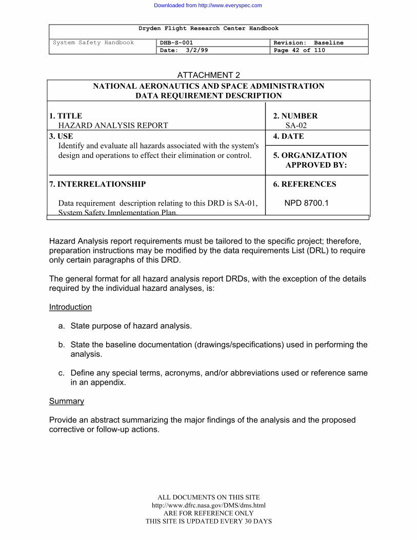
Dryden Flight Research Center Handbook
System Safety Handbook DHB-S-001 Revision: Baseline Date: 3/2/99 Page 42 of 110
ATTACHMENT 2 NATIONAL AERONAUTICS AND SPACE ADMINISTRATION
DATA REQUIREMENT DESCRIPTION 1. TITLE 2. NUMBER HAZARD ANALYSIS REPORT SA-02 3. USE 4. DATE
Identify and evaluate all hazards associated with the system's design and operations to effect their elimination or control. 5. ORGANIZATION APPROVED BY: 7. INTERRELATIONSHIP 6. REFERENCES
Data requirement description relating to this DRD is SA-01, NPD 8700.1 System Safety Implementation Plan. Hazard Analysis report requirements must be tailored to the specific project; therefore, preparation instructions may be modified by the data requirements List (DRL) to require only certain paragraphs of this DRD. The general format for all hazard analysis report DRDs, with the exception of the details required by the individual hazard analyses, is: Introduction a. State purpose of hazard analysis. b. State the baseline documentation (drawings/specifications) used in performing the
analysis. c. Define any special terms, acronyms, and/or abbreviations used or reference same
in an appendix. Summary Provide an abstract summarizing the major findings of the analysis and the proposed corrective or follow-up actions.
ALL DOCUMENTS ON THIS SITE http://www.dfrc.nasa.gov/DMS/dms.html
ARE FOR REFERENCE ONLY THIS SITE IS UPDATED EVERY 30 DAYS
Downloaded from http://www.everyspec.com
Dryden Flight Research Center Handbook
System Safety Handbook DHB-S-001 Revision: Baseline Date: 3/2/99 Page 43 of 110
Technical Discussion
a. System description. State purpose and intended use of item and provide a description of the system hardware and configuration. List components of subsystems and provide flowcharts.. flow diagrams, and procedures, to describe the intended operation of the system to provide a system model for conducting the analysis.
b. Analysis assumptions and ground rules. State the basic ground rules and
assumptions used in performance (including risk assessment criteria) of the analysis to ensure a baseline for understanding by reviewer.
c. Detailed discussion. Provide a detailed discussion of the analysis, the safety
critical areas identified, and a summary table of all hazards identified. Conclusions and Recommendations State in brief terms the major references that can be drawn from the discussion based entirely on-the information stated in the detailed discussion. Provide recommendations and design methodology used for the correction of hazards. References and Appendices Provide a list of references in the order they appear in the report and include appendices necessary to an immediate understanding of the discussion. Worksheet Data Requirements Include under this heading the minimum requirements for the hazard analysis required for systematically documenting the analysis. Preliminary Hazard Analysis Provide the following information for each hazard identified: a. Description of hazard, including cause and effect. b. The hazard severity level. c. Recommended corrective actions
1. Hardware modifications/safety design features 2. Text and location of proposed labels
ALL DOCUMENTS ON THIS SITE http://www.dfrc.nasa.gov/DMS/dms.html
ARE FOR REFERENCE ONLY THIS SITE IS UPDATED EVERY 30 DAYS
Downloaded from http://www.everyspec.com

Dryden Flight Research Center Handbook
System Safety Handbook DHB-S-001 Revision: Baseline Date: 3/2/99 Page 44 of 110
d. Remarks (references, explanations, descriptions etc.)
System/Subsystem Hazard Analysis (S/SSHA) Specific analysis techniques which may be used in the course of performing the S/SSHA's are listed below. Reports for these techniques will follow format and content requirements as contractually defined.
• Fault-hazard analysis (FHA)
• Fault-tree analysis
• Sneak circuit analysis
When the FHA technique is used, the information indicated below shall be provided for each hazard identified. a. Component. Identify he major functional activity or hardware components within
the subsystem being analyzed. The major component should be identified by part. number and descriptive title.
b. Failure mode. Identify all credible failure modes which are possible for the
identified major component. The FMEA (failure modes and effects analysis) should supply this information., whenever applicable.
c. Failure rate. When performing quantitative analyses, enter a probability. of failure
estimate of the component in the indicated failure mode. This is the component's primary failure rate.. The source of data must be indicated but is normally the FMEA.
d. System Operational mode. Identify the system mode of operation in which the major-component is -operating during the indicated failure mode.' e. Effect of failure on subsystem. Identify the direct effect, on the subsystem and components with in -the subsystem, of the indicated component failure for the indicated system operational mode. f. Secondary factors-that may cause failure. Identify the abnormal and
out-of-tolerance conditions (generally environmental) which can cause the indicated failure mode under investigation. The specific tolerance limits must be given.
g. Upstream events that may "command" the failure mode. Identify those functions, events, or failures which directly place the component in the indicated failure mode.
ALL DOCUMENTS ON THIS SITE http://www.dfrc.nasa.gov/DMS/dms.html
ARE FOR REFERENCE ONLY THIS SITE IS UPDATED EVERY 30 DAYS
Downloaded from http://www.everyspec.com
Dryden Flight Research Center Handbook
System Safety Handbook DHB-S-001 Revision: Baseline Date: 3/2/99 Page 45 of 110
h. Hazard classification. Provide a qualitative measure of significance for the
indicated potential effect of each identified component failure mode. i. Effect of failure on system. Identify the direct effect on the system of the
component failure on the indicated system operational mode. j. Remarks. Provide any additional information which may be pertinent to the
analysis and is normally used to identify the recommended and actual means of hazard control.
Operating and Support Hazard Analysis
a. Specific task or general operation (subsystem or system). Identify and describe
each operation, task, or procedure to the lowest level of detail possible to analyze the associated hazards. In the event operations have not been definitized, assumptions should be made to facilitate the analysis; however, the assumptions should be noted as such
b. Phase, mode, function. Identify the phase, mode, or function of the operation
under analysis. This generally provides useful information necessary in identifying hazards.
c. Criteria, constraints, energy sources. Identify pertinent criteria and constraints of
the operation under analysis which may affect safety (for example, the particular magnitude of voltage, current, pressure, radar frequency, etc.). It is also used to identify the presence and magnitude of any energy sources, such as propellants, explosives, velocity, etc. Generally speaking, this column is used to identify hazardous elements.
d. Hazardous conditions and their impact. Identify hazardous conditions involved in
the operation under analysis and the potential impact or effect. of the hazardous conditions.
e. Hazard classification. Provide a qualitative measure of the risk assessment of
each identified hazardous condition. f. Safety guidelines and requirements. Provide recommended preventive measures
for eliminating or controlling the identified hazardous conditions. These recommendations may take the form of guidelines, requirements, further analysis, etc.
ALL DOCUMENTS ON THIS SITE http://www.dfrc.nasa.gov/DMS/dms.html
ARE FOR REFERENCE ONLY THIS SITE IS UPDATED EVERY 30 DAYS
Downloaded from http://www.everyspec.com
Dryden Flight Research Center Handbook
System Safety Handbook DHB-S-001 Revision: Baseline Date: 3/2/99 Page 46 of 110
g. Comments, correlation to data sources. Record pertinent information to the
analysis which may facilitate someone else tracking the analysis at a later date. Included would be such things as design drawing and data used, source or derivation of requirements, calculations, concepts, etc. Also, key comments or ideas of the analyst should be recorded.
ALL DOCUMENTS ON THIS SITE http://www.dfrc.nasa.gov/DMS/dms.html
ARE FOR REFERENCE ONLY THIS SITE IS UPDATED EVERY 30 DAYS
Downloaded from http://www.everyspec.com
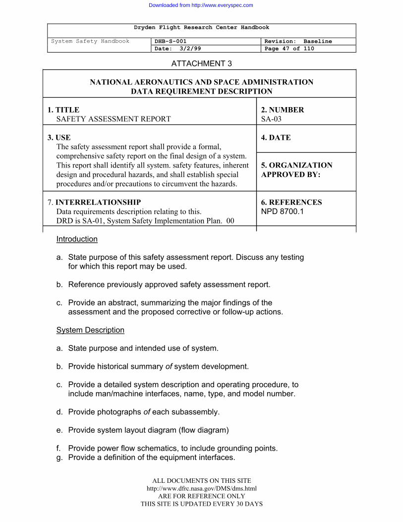
Dryden Flight Research Center Handbook
System Safety Handbook DHB-S-001 Revision: Baseline Date: 3/2/99 Page 47 of 110
ALL DOCUMENTS ON THIS SITE http://www.dfrc.nasa.gov/DMS/dms.html
ARE FOR REFERENCE ONLY THIS SITE IS UPDATED EVERY 30 DAYS
ATTACHMENT 3
NATIONAL AERONAUTICS AND SPACE ADMINISTRATION DATA REQUIREMENT DESCRIPTION
1. TITLE 2. NUMBER
SAFETY ASSESSMENT REPORT SA-03
3. USE 4. DATE The safety assessment report shall provide a formal, comprehensive safety report on the final design of a system. This report shall identify all system. safety features, inherent 5. ORGANIZATION design and procedural hazards, and shall establish special APPROVED BY: procedures and/or precautions to circumvent the hazards.
7. INTERRELATIONSHIP 6. REFERENCES Data requirements description relating to this. NPD 8700.1
DRD is SA-01, System Safety Implementation Plan. 00
Introduction
a. State purpose of this safety assessment report. Discuss any testing for which this report may be used.
b. Reference previously approved safety assessment report. c. Provide an abstract, summarizing the major findings of the
assessment and the proposed corrective or follow-up actions. System Description a. State purpose and intended use of system. b. Provide historical summary of system development. c. Provide a detailed system description and operating procedure, to
include man/machine interfaces, name, type, and model number. d. Provide photographs of each subassembly. e. Provide system layout diagram (flow diagram) f. Provide power flow schematics, to include grounding points. g. Provide a definition of the equipment interfaces.
Downloaded from http://www.everyspec.com

Dryden Flight Research Center Handbook
System Safety Handbook DHB-S-001 Revision: Baseline Date: 3/2/99 Page 48 of 110
h. Describe the maintenance concept (which functions are accomplished
at which maintenance levels). i. As applicable, describe any other system(s) which will. be tested or
operated in combination with this system.
System Operations a. Briefly describe or reference the procedures for operating the system. Discuss the
safety design features and controls incorporated into the system as they relate to the operating procedures.
b. Describe any special safety operational procedures needed to assure safe
operations including emergency procedures. c. Describe anticipated operating environments and any specific skills required for
safe operations, maintenance, or disposal. d. Describe any special facility requirements or personnel equipment to support the
system. System Safety Engineering a. Include a short abstract of the results of-the System Safety Program. b. Provide any software safety features and software safety analysis of software
controlling hardware where the effects of failures are safety critical. List all software safety-critical hazards identified and corrective measures/procedures that are recommended and implemented. if no software safety issues can be identified or are applicable to the system under analysis, then a statement to that effect shall be included.
c. Furnish a copy of all system safety data, hazard analysis, and reports generated
during design, development, production, and testing to identify hazardous conditions inherent in the system. A summary of all engineering change proposals (ECP's) and waivers that have safety implications shall be enclosed.
(1) Describe or reference the safety criteria and methodology used to classify
and rank hazardous conditions.
(2) Summarize the results of hazard analysis and tests conducted and the
impact, if any, on system operations/mission accomplishments due to hazards that have not been eliminated. include a list of all significant hazards along with specific. safety recommendations or precautions required to
ALL DOCUMENTS ON THIS SITE http://www.dfrc.nasa.gov/DMS/dms.html
ARE FOR REFERENCE ONLY THIS SITE IS UPDATED EVERY 30 DAYS
Downloaded from http://www.everyspec.com
Dryden Flight Research Center Handbook
System Safety Handbook DHB-S-001 Revision: Baseline Date: 3/2/99 Page 49 of 110
ensure the safety of personnel and property. Categorize the list of hazards as to whether or not they may be expected under normal or abnormal operating conditions. Provide current status of any .outstanding corrective actions.
d. If system safety hazard analysis is not required by DRL, then include the
following:
(1) List all hazards, including software induced safety critical hazards that have been identified and considered from the inception of the program in an appendix to the Safety Assessment Report. The list should be broken down to the subsystem or major component level and should be presented in a tabular format.
(2) For each hazard listed, provide a risk assessment.
e. If the system does not contain or generate-hazardous materials (i.e.
explosives, toxic, radioactive, carcinogenic, etc.) a statement to that effect shall be included. For all hazardous materials generated by or used in the
system, a Material Safety Data Sheet, shall be prepared to include the following information:
(1) Material identification as to type, quantity, and potential hazards.
(2) Safety precautions and procedures necessary during use, storage
transportation., and disposal.
f. Provide a comparison of actual hardware parameters with established safety requirements in the equipment specification. This comparison shall be in a tabular format listing "Safety Critical" in another column. The analysis should show compliance/noncompliance of the listed safety criteria and provide justification for any noncompliance.
Conclusions and Recommendations:
a. State whether all identified hazards have been eliminated or controlled and that
the system is completely safe and suitable for testing and operation or whether it is safe for testing with exceptions.
b. List exceptions for all known and potential hazards that may be encountered
and-the specific safety recommendations to insure the safety of personnel and preservation of material and property. Related hazards should be classified as to whether they are expected to occur under normal or abnormal operating conditions.
ALL DOCUMENTS ON THIS SITE http://www.dfrc.nasa.gov/DMS/dms.html
ARE FOR REFERENCE ONLY THIS SITE IS UPDATED EVERY 30 DAYS
Downloaded from http://www.everyspec.com

Dryden Flight Research Center Handbook
System Safety Handbook DHB-S-001 Revision: Baseline Date: 3/2/99 Page 50 of 110
c. High-light any known safety or health problems that will require further
investigation during testing. References. List all pertinent references such as test reports, Government safety inspection reports, preliminary operating manuals, technical manuals, and maintenance manuals. Appendix. The appendix shall contain-charts, graphs, photos, or data which are too cumbersome for inclusion in the previous sections, or are applicable to more than one section, It may also contain detailed formulation or analysis which is more conveniently placed in an Appendix. Safety Assessment Report (Update): If you have developed and submitted a Safety Assessment Report during a previous contract, it shall be updated to conform to the requirements stipulated in this DRD. in addition, the following shall be-addressed:
1. Discuss any new safety design features and controls added into the system as they relate to operating procedures.
2. List all safety deficiencies/shortcomings identified in test reports, Equipment
Performance Reports, Government safety inspection reports, hazards introduced due to equipment design
changes, and those hazards identified as not being eliminated since last submission of Safety Assessment Report List shall be provided as an appendix to the Safety Assessment Report.
3. Summarize all new system safety data generated during production and
testing. when it is found that the item presents no old or new hazards, the basis for such a determination and the supporting evidence shall be included.
ALL DOCUMENTS ON THIS SITE http://www.dfrc.nasa.gov/DMS/dms.html
ARE FOR REFERENCE ONLY THIS SITE IS UPDATED EVERY 30 DAYS
Downloaded from http://www.everyspec.com
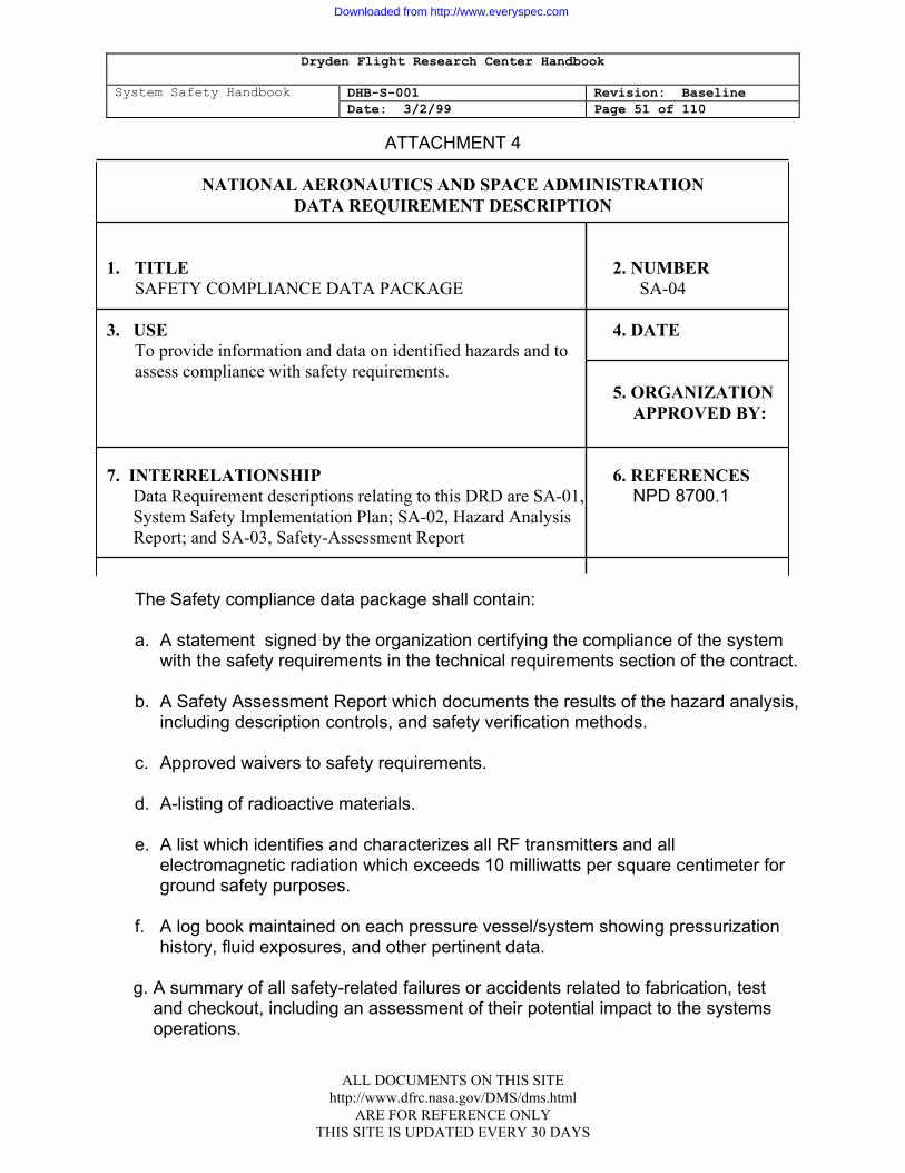
Dryden Flight Research Center Handbook
System Safety Handbook DHB-S-001 Revision: Baseline Date: 3/2/99 Page 51 of 110
ALL DOCUMENTS ON THIS SITE http://www.dfrc.nasa.gov/DMS/dms.html
ARE FOR REFERENCE ONLY THIS SITE IS UPDATED EVERY 30 DAYS
ATTACHMENT 4
NATIONAL AERONAUTICS AND SPACE ADMINISTRATION DATA REQUIREMENT DESCRIPTION
1. TITLE 2. NUMBER
SAFETY COMPLIANCE DATA PACKAGE SA-04 3. USE 4. DATE
To provide information and data on identified hazards and to assess compliance with safety requirements.
5. ORGANIZATION APPROVED BY: 7. INTERRELATIONSHIP 6. REFERENCES Data Requirement descriptions relating to this DRD are SA-01, NPD 8700.1 System Safety Implementation Plan; SA-02, Hazard Analysis Report; and SA-03, Safety-Assessment Report
The Safety compliance data package shall contain: a. A statement signed by the organization certifying the compliance of the system
with the safety requirements in the technical requirements section of the contract. b. A Safety Assessment Report which documents the results of the hazard analysis,
including description controls, and safety verification methods. c. Approved waivers to safety requirements. d. A-listing of radioactive materials. e. A list which identifies and characterizes all RF transmitters and all
electromagnetic radiation which exceeds 10 milliwatts per square centimeter for ground safety purposes.
f. A log book maintained on each pressure vessel/system showing pressurization
history, fluid exposures, and other pertinent data. g. A summary of all safety-related failures or accidents related to fabrication, test
and checkout, including an assessment of their potential impact to the systems operations.
Downloaded from http://www.everyspec.com

Dryden Flight Research Center Handbook
System Safety Handbook DHB-S-001 Revision: Baseline Date: 3/2/99 Page 52 of 110
h. A summary of the test, analyses, and/or inspection performed to show
verification of the related safety requirements. i. Detailed technical operating procedures (including contingency procedures) for
operations which are hazardous in nature.
ALL DOCUMENTS ON THIS SITE http://www.dfrc.nasa.gov/DMS/dms.html
ARE FOR REFERENCE ONLY THIS SITE IS UPDATED EVERY 30 DAYS
Downloaded from http://www.everyspec.com
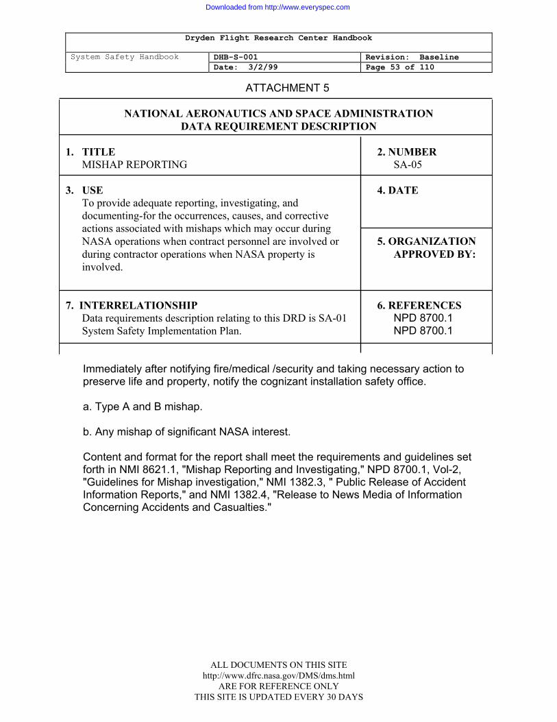
Dryden Flight Research Center Handbook
System Safety Handbook DHB-S-001 Revision: Baseline Date: 3/2/99 Page 53 of 110
ALL DOCUMENTS ON THIS SITE http://www.dfrc.nasa.gov/DMS/dms.html
ARE FOR REFERENCE ONLY THIS SITE IS UPDATED EVERY 30 DAYS
ATTACHMENT 5
NATIONAL AERONAUTICS AND SPACE ADMINISTRATION DATA REQUIREMENT DESCRIPTION
1. TITLE 2. NUMBER
MISHAP REPORTING SA-05 3. USE 4. DATE
To provide adequate reporting, investigating, and documenting-for the occurrences, causes, and corrective actions associated with mishaps which may occur during NASA operations when contract personnel are involved or 5. ORGANIZATION during contractor operations when NASA property is APPROVED BY: involved.
7. INTERRELATIONSHIP 6. REFERENCES
Data requirements description relating to this DRD is SA-01 NPD 8700.1 System Safety Implementation Plan. NPD 8700.1
Immediately after notifying fire/medical /security and taking necessary action to preserve life and property, notify the cognizant installation safety office. a. Type A and B mishap.
b. Any mishap of significant NASA interest.
Content and format for the report shall meet the requirements and guidelines set forth in NMI 8621.1, "Mishap Reporting and Investigating," NPD 8700.1, Vol-2, "Guidelines for Mishap investigation," NMI 1382.3, " Public Release of Accident Information Reports," and NMI 1382.4, "Release to News Media of Information Concerning Accidents and Casualties."
Downloaded from http://www.everyspec.com

Dryden Flight Research Center Handbook
System Safety Handbook DHB-S-001 Revision: Baseline Date: 3/2/99 Page 54 of 110
APPENDIX C: APPLICABLE DOCUMENTS
I. Agency Requirements A. KHB 1700.7 Space Transportation System Payload Ground
Safety Handbook B. NPD 8700.1 Basic Safety Manual C. NPD 8700.1 Guidelines for Mishap Investigations D. NPD 8700.1 Safety Policy and Requirements For Payloads
Using the Space Transportation System (STS) E. NHB 5300.4 (1D-2) Safety, Reliability, Maintainability, and Quality
Provisions for the Space Shuttle Program F. NHB 6000.1 Packaging, Handling, and Transportation for
Aeronautical and Space Systems, Equipment, and Associated Components
G. NHB 8820.2 Facility Project Implementation Handbook H. NMI 1800.3 NASA Environmental Health Program I. NMI 8621.1 Mishap Reporting and Investigating J. NMI 8710.2 NASA Safety and Health Programs II. Design Requirements, Handbooks, and Guidelines A. JSC-02681 Nonmetallic Materials Design Guidelines and
Test Data Handbook B. JSC-07700 Space Shuttle System Payload
Accommodation Handbook C. JSC-09604 JSC Government -Furnished Equipment
Materials Selection List and Materials Documentation Procedures.
D. JSC-10615 Shuttle EVA Description and Design Criteria E. JSC-11123 Space Transportation System Payload Safety
Guidelines Handbook
ALL DOCUMENTS ON THIS SITE http://www.dfrc.nasa.gov/DMS/dms.html
ARE FOR REFERENCE ONLY THIS SITE IS UPDATED EVERY 30 DAYS
Downloaded from http://www.everyspec.com
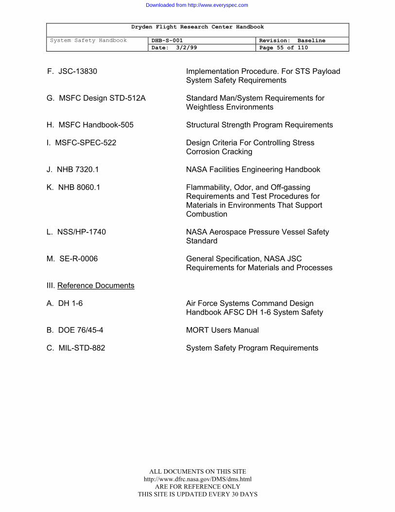
Dryden Flight Research Center Handbook
System Safety Handbook DHB-S-001 Revision: Baseline Date: 3/2/99 Page 55 of 110
F. JSC-13830 Implementation Procedure. For STS Payload
System Safety Requirements G. MSFC Design STD-512A Standard Man/System Requirements for
Weightless Environments H. MSFC Handbook-505 Structural Strength Program Requirements I. MSFC-SPEC-522 Design Criteria For Controlling Stress
Corrosion Cracking J. NHB 7320.1 NASA Facilities Engineering Handbook K. NHB 8060.1 Flammability, Odor, and Off-gassing
Requirements and Test Procedures for Materials in Environments That Support Combustion
L. NSS/HP-1740 NASA Aerospace Pressure Vessel Safety
Standard M. SE-R-0006 General Specification, NASA JSC
Requirements for Materials and Processes
III. Reference Documents
A. DH 1-6 Air Force Systems Command Design Handbook AFSC DH 1-6 System Safety
B. DOE 76/45-4 MORT Users Manual C. MIL-STD-882 System Safety Program Requirements
ALL DOCUMENTS ON THIS SITE http://www.dfrc.nasa.gov/DMS/dms.html
ARE FOR REFERENCE ONLY THIS SITE IS UPDATED EVERY 30 DAYS
Downloaded from http://www.everyspec.com
Dryden Flight Research Center Handbook
System Safety Handbook DHB-S-001 Revision: Baseline Date: 3/2/99 Page 56 of 110
APPENDIX D: SYSTEM SAFETY ANALYSIS TECHNIQUES 1.1 INTRODUCTION
The selection of the most suitable analytical tool for a particular system safety task may be difficult. A reference chart which could provide correlation between the appropriate technique and the specific set of objectives, equipment, and constraints may be useful. Because of the extreme diversities in hardware factors and program considerations involved in the various situations where system safety analyses may be required, a universal system safety analysis technique selection chart is not possible. Instead, a method using certain basic guidelines-is provided for use in applying a systematic objective process to select the most appropriate system safety analytical technique. These guidelines are presented in a series of interrelated matrix charts, which must be cross-referenced for an understanding of the symbols and terms employed (figures D-1. D-2, D-3).
2.1 BASIC CONSIDERATIONS
In performing an objective evaluation of the appropriateness of system safety analytical tools for a given situation, and how to implement those selected, the following basic questions should be resolved:
1. Who will have a need for the results or information to be generated? 2. When will this information be needed? 3. In what detail and format will the data be most useful to the recipient? 4. What input information, data, and drawings will be needed before the analysis
or study can be performed? 5. In what time frame should the analysis be initiated, reviewed, completed,
submitted, and updated? 6. How will inputs required from subcontractors be provided to the responsible
associated contractors; and inputs required by the integrating contractor be provided from the associated contractor in a timely and effective manner?
7. What must be added to contractual agreements, (e.g. work statements and
contract data requirement list), to assure the desired task management and data flow control.
ALL DOCUMENTS ON THIS SITE http://www.dfrc.nasa.gov/DMS/dms.html
ARE FOR REFERENCE ONLY THIS SITE IS UPDATED EVERY 30 DAYS
Downloaded from http://www.everyspec.com
Dryden Flight Research Center Handbook
System Safety Handbook DHB-S-001 Revision: Baseline Date: 3/2/99 Page 57 of 110
3.1 GUIDELINE DESCRIPTION
The following reference guidelines (Figures D-1 through D-3) are cross-referenced with each other for brevity, and therefore must be treated as a complete unit, rather than individual charts. These have been prepared to assist the non-system safety specialist in selecting the particular analytical techniques for a given need or set of objectives. The approach taken was as follows:
1. A list of generalized typical reasons/objectives for performing system safety
analyses (note, special purpose safety studies, range safety data, nuclear safety data, etc. - are not covered) was developed. The listed reasons are documented in Figure D-1, and given a reference code number (Ref. Code), used to cross-reference that particular objective in the related matrix charts.
2. A matrix chart (Figure D-2) was prepared, relating each system safety
analytical technique to the applicable reasons listed in Figure D-1. In this effort the following rationale was adopted:
a. Each reason was. considered in turn for each technique, and assigned to
one of three classes of relative applicability, i.e., primary, secondary, or contributory, or non-applicable.
b. A primary classification means that the technique was developed to
accomplish the Objective indicated.
c. A secondary classification means that the technique will accomplish at least most of the objective indicated, but not as well as sane other technique with a "primary" classification.
d. A contributory classification means that the-technique will provide output
data usable for satisfying the objective when combined with other analyses and for studies.
e. The matrix was then completed, assigning the reference code number from
Figure D-1 to the appropriate column in Figure D-2.
f. For each system safety analytical technique listed, a subsystem and system line was provided. For the purpose of this discussion, system (S) refers to the effort planned which is to consider the total system or program under evaluation, or at least does not have any significant part or subdivision intentionally omitted; subsystem (Sub) refers to the effort accomplished on any subdivision, subsystem, part-or element of a defined system or project.
3. Since most techniques were assigned two or three "primary" objectives and many objectives assigned to several techniques, a need to better indicate the
ALL DOCUMENTS ON THIS SITE http://www.dfrc.nasa.gov/DMS/dms.html
ARE FOR REFERENCE ONLY THIS SITE IS UPDATED EVERY 30 DAYS
Downloaded from http://www.everyspec.com
Dryden Flight Research Center Handbook
System Safety Handbook DHB-S-001 Revision: Baseline Date: 3/2/99 Page 58 of 110
relative effectiveness (on a general basis) of the various techniques for the listed objectives was needed for guideline purposes. This was accomplished by means of a slightly modified matrix (Figure D-3), which provides for a single point technique/ reason evaluation rating for each possible combination. The explanation of the rating symbols used on this matrix was indicated in Figure D-3.
4. Figure D-3 shows the sequence of technique initiation based on a typical
major. system life-cycle phase, and the manner by which input and output data should be transmitted. The interrelationships continually occurring between the analytical process and the system design, schedule, and ,testing are also illustrated as a reminder that system safety analysis cannot be effectively performed in any manner isolated from the other ongoing aspects of the program.
ALL DOCUMENTS ON THIS SITE http://www.dfrc.nasa.gov/DMS/dms.html
ARE FOR REFERENCE ONLY THIS SITE IS UPDATED EVERY 30 DAYS
Downloaded from http://www.everyspec.com
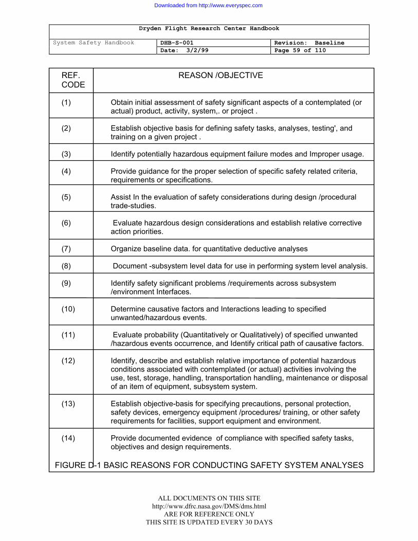
Dryden Flight Research Center Handbook
System Safety Handbook DHB-S-001 Revision: Baseline Date: 3/2/99 Page 59 of 110
ALL DOCUMENTS ON THIS SITE http://www.dfrc.nasa.gov/DMS/dms.html
ARE FOR REFERENCE ONLY THIS SITE IS UPDATED EVERY 30 DAYS
REF. REASON /OBJECTIVE CODE
(1) Obtain initial assessment of safety significant aspects of a contemplated (or
actual) product, activity, system,. or project . (2) Establish objective basis for defining safety tasks, analyses, testing', and
training on a given project . (3) Identify potentially hazardous equipment failure modes and Improper usage. (4) Provide guidance for the proper selection of specific safety related criteria,
requirements or specifications. (5) Assist In the evaluation of safety considerations during design /procedural
trade-studies. (6) Evaluate hazardous design considerations and establish relative corrective
action priorities. (7) Organize baseline data. for quantitative deductive analyses (8) Document -subsystem level data for use in performing system level analysis. (9) Identify safety significant problems /requirements across subsystem
/environment Interfaces. (10) Determine causative factors and Interactions leading to specified
unwanted/hazardous events. (11) Evaluate probability (Quantitatively or Qualitatively) of specified unwanted
/hazardous events occurrence, and Identify critical path of causative factors. (12) Identify, describe and establish relative importance of potential hazardous
conditions associated with contemplated (or actual) activities involving the use, test, storage, handling, transportation handling, maintenance or disposal of an item of equipment, subsystem system.
(13) Establish objective-basis for specifying precautions, personal protection,
safety devices, emergency equipment /procedures/ training, or other safety requirements for facilities, support equipment and environment.
(14) Provide documented evidence of compliance with specified safety tasks,
objectives and design requirements.
FIGURE D-1 BASIC REASONS FOR CONDUCTING SAFETY SYSTEM ANALYSES
Downloaded from http://www.everyspec.com
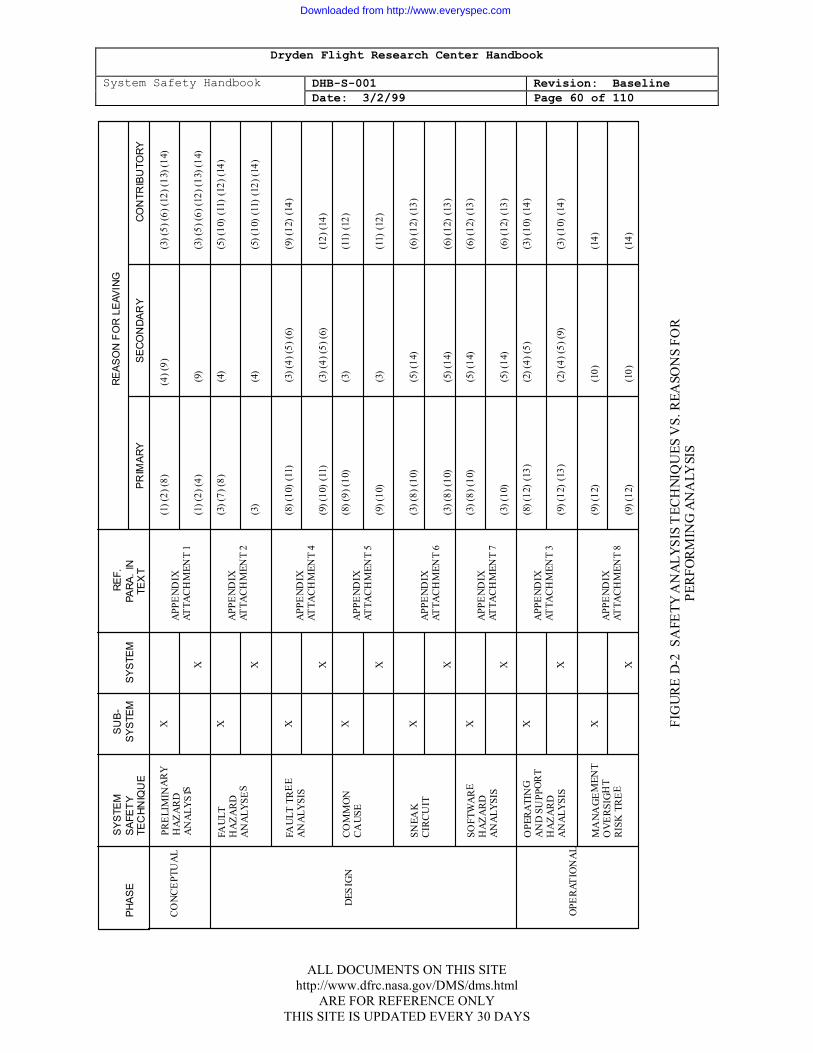
Dryden Flight Research Center Handbook
System Safety Handbook DHB-S-001 Revision: Baseline Date: 3/2/99 Page 60 of 110
SY
STEM
S
UB-
REF
.
RE
ASO
N F
OR
LEAV
ING
PH
ASE
SA
FETY
SYS
TEM
SYST
EM
P
ARA.
IN
TEC
HNIQ
UE
T
EXT
P
RIM
ARY
S
ECO
NDA
RY
CO
NTR
IBU
TORY
CO
NC
EPT
UA
L
PRE
LIM
INA
RY
X
(1
) (2)
(8)
(4) (
9)
(3)
(5) (
6) (1
2) (1
3) (1
4)
H
AZ
AR
D
A
PPE
ND
IX
AN
ALY
SIS
AT
TAC
HM
ENT
1
X
(1) (
2) (4
)
(
9)
(3)
(5) (
6) (1
2) (1
3) (1
4)
FA
ULT
X
(3
) (7)
(8)
(4)
(
5) (1
0) (
11)
(12)
(14)
H
AZ
AR
D
A
PPE
ND
IX
AN
ALY
SES
AT
TAC
HM
ENT
2
X
(3
)
(4)
(
5) (1
0) (
11)
(12)
(14)
F
AU
LT T
RE
E
X
(8
) (10
) (1
1)
(3)
(4) (
5) (6
)
(9)
(12)
(14
) A
NA
LYSI
S
APP
EN
DIX
AT
TAC
HM
ENT
4
X
(9
) (10
) (1
1)
(3)
(4) (
5) (6
)
(12
) (14
) C
OM
MO
N
X
(8) (
9) (1
0)
(3)
(
11)
(12)
C
AU
SE
A
PPE
ND
IX
A
TTA
CH
MEN
T 5
X
(9) (
10)
(
3)
(11
) (1
2)
SN
EAK
X
(3
) (8)
(10)
(
5) (1
4)
(
6) (1
2) (
13)
CIR
CU
IT
A
PPE
ND
IX
A
TTA
CH
MEN
T 6
X
(3) (
8) (1
0)
(5)
(14)
(6)
(12)
(13
) S
OFT
WA
RE
X
(3
) (8)
(10)
(
5) (1
4)
(
6) (1
2) (
13)
HA
ZA
RD
APP
EN
DIX
A
NA
LYSI
S
AT
TAC
HM
ENT
7
X
(3
) (10
)
(5)
(14)
(6)
(12)
(13
) O
PER
ATI
NG
X
(8
) (12
) (1
3)
(2)
(4) (
5)
(
3) (1
0) (
14)
AN
D S
UPP
OR
T
APP
EN
DIX
H
AZ
AR
D
AT
TAC
HM
ENT
3
AN
ALY
SIS
X
(9) (
12)
(13)
(
2) (4
) (5)
(9)
(
3) (1
0) (
14)
MA
NA
GE
MEN
T
X
(9
) (12
)
(10
)
(
14)
OV
ER
SIG
HT
A
PPE
ND
IX
RIS
K T
RE
E
AT
TAC
HM
ENT
8
X
(9
) (12
)
(10
)
(
14)
DES
IGN
OPE
RAT
ION
AL
FIG
UR
E D
-2 S
AFE
TY A
NA
LYSI
S T
ECH
NIQ
UES
VS.
REA
SON
S FO
R
PER
FOR
MIN
G A
NA
LYSI
S
ALL DOCUMENTS ON THIS SITE http://www.dfrc.nasa.gov/DMS/dms.html
ARE FOR REFERENCE ONLY THIS SITE IS UPDATED EVERY 30 DAYS
Downloaded from http://www.everyspec.com
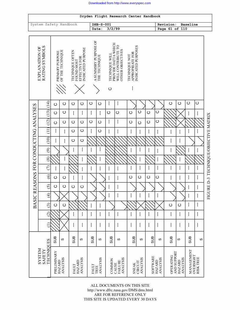
Dryden Flight Research Center Handbook
System Safety Handbook DHB-S-001 Revision: Baseline Date: 3/2/99 Page 61 of 110
BA
SIC
REA
SON
S FO
R C
ON
DU
CTIN
G A
NA
LYSE
S
SYST
EM
E
XPL
AN
ATIO
N O
F
SA
FETY
RA
TIN
G S
YM
BO
LS
T
ECH
NIQ
UES
(
1)
(2
) (
3)
(4)
(5
)
(6)
(7)
(8
) (
9)
(10)
(1
1) (
12)
(13)
(14
)
PREL
IMIN
AR
Y
HA
ZA
RD
AN
ALY
SIS
FAU
LT
HA
ZA
RD
AN
ALY
SIS
FAU
LT
TREE
A
NA
LYSI
S C
OM
MO
N
CA
USE
FA
ILU
RE
AN
ALY
SIS
SNEA
K
CIR
CUIT
A
NA
LYSI
S SO
FTW
AR
E H
AZ
ARD
A
NA
LYSI
S O
PER
ATIN
G
AN
D S
UPP
ORT
H
AZ
ARD
A
NA
LYSI
S M
AN
AG
EMEN
T O
VE
RSIG
HT
RIS
K T
REE
SU
B
S
S
UB
S
SU
B
S
S
UB
S
SU
B
S
S
UB
S
SU
B
S
S
UB
S
C
C
C
-
--
-
--
---
C
C
C
C
C
C
---
--
-
---
---
C
C
C
---
--
-
C
-
--
-
--
C
C
C
-
--
C
---
--
-
C
-
--
---
---
--
-
C
C
C
-
--
C
---
--
- -
--
---
-
--
---
C
-
--
C
---
--
- -
--
---
---
-
--
C
C
-
--
C
---
--
-
---
---
--
-
---
---
--
-
C
---
---
--
-
---
---
--
-
---
---
--
-
C
---
---
--
-
---
C
---
-
--
---
C
C
--
-
---
-
--
C
-
--
---
---
-
--
C
C
--
-
---
-
--
C
-
--
---
---
C
C
--
-
---
-
--
C
-
--
---
---
-
--
C
C
--
-
---
C
---
-
--
---
--
- -
--
C
---
--
-
C
---
---
---
---
---
C
--
-
---
---
--
- -
--
---
---
---
--
-
---
C
--
-
---
---
--
- -
--
---
---
---
--
-
---
C
FIG
UR
E D
-3 T
ECH
NIQ
UE/
OB
JEC
TIV
E M
ATR
IX
C
---
PRIM
ARY
PU
RPO
SE
OF
THE
TEC
HN
IQU
E TE
CH
NIQ
UE
OFT
EN
FOU
ND
MO
ST
EFFE
CTI
VE
FOR
IN
DIC
ATED
PU
RPO
SE
A S
UM
MSR
Y P
URP
OSE
OF
THE
TEC
HN
IQU
E TE
CH
NIQ
UE
WIL
L PR
OV
IDE
DAT
TA W
HIC
H
WIL
L C
ON
TRIB
UTE
TO
O
THER
OB
JECT
IVES
TE
CH
NIQ
UE
NO
T A
PPR
OPR
IATE
FO
R
IND
ICAT
ED P
URP
OSE
S
ALL DOCUMENTS ON THIS SITE http://www.dfrc.nasa.gov/DMS/dms.html
ARE FOR REFERENCE ONLY THIS SITE IS UPDATED EVERY 30 DAYS
Downloaded from http://www.everyspec.com
Dryden Flight Research Center Handbook
System Safety Handbook DHB-S-001 Revision: Baseline Date: 3/2/99 Page 62 of 110
4.l GUIDELINE USAGE INSTRUCTIONS
In attempting to use the guidelines and references provided in this appendix, the following is suggested:
1. First consider the basic objectives (Figure D-1) which apply to your particular
situation, and prepare a listing. 2. Compare the list of selected objectives with the information provided in Figures
D-2 and D-3 to select those candidate techniques which appear to .best satisfy your primary requirements.
3. Considering the results of the questions addressed in paragraph 2.1, organize
the implementation plan of the technique candidates, and make the final trade-off decisions through the preparation of a detailed system safety analysis plan, which may be used as part of the overall system safety program plan.
ALL DOCUMENTS ON THIS SITE http://www.dfrc.nasa.gov/DMS/dms.html
ARE FOR REFERENCE ONLY THIS SITE IS UPDATED EVERY 30 DAYS
Downloaded from http://www.everyspec.com
Dryden Flight Research Center Handbook
System Safety Handbook DHB-S-001 Revision: Baseline Date: 3/2/99 Page 63 of 110
ATTACHMENT 1: PRELIMINARY HAZARD ANALYSIS (PHA)
1.1 PURPOSE
1. The PHA is usually the initial safety analysis performed for a project and the purposes of this analysis technique are to: a. Identify hazardous elements, hazardous conditions, and their causes. b. Determine the effects of these hazardous elements and conditions on the
subsystem, system, and overall project. c. Categorize the severity level of each hazardous element or condition. d. Identify proposed corrective actions for eliminating the hazardous element
or condition, or minimizing the hazard effects.
2. The data derived from the PHA will provide an input to other initial system safety activities such as the identification of:
a. Potential problem areas associated with hardware, software, or procedural interfaces and interactions..
b. Safety design or procedural requirements.
c. Priorities for scheduling the safety effort.
d. Areas requiring testing, further analyses, or trade studies.
2.1 DESCRIPTION
The PHA is a systematic safety analysis used to identify critical safety areas, to evaluate major hazards, and to identify the safety design requirements for the project. The format for documenting the PHA is usually a columnar form A top-level fault tree analysis may be developed to systematically guide the analysis effort and place emphasis on critical areas in the early stages of project development. See Appendix D, Attachment 4, for a discussion of the Fault Tree Analysis. The following data are required to perform a PHA:
1. The proposed or actual systems configuration or operation from drawings, scenarios, specifications, and analyses.
2. Hazard analyses, mishap data, and lessons learned from similar systems . and
projects. 3. Trade studies.
ALL DOCUMENTS ON THIS SITE http://www.dfrc.nasa.gov/DMS/dms.html
ARE FOR REFERENCE ONLY THIS SITE IS UPDATED EVERY 30 DAYS
Downloaded from http://www.everyspec.com
Dryden Flight Research Center Handbook
System Safety Handbook DHB-S-001 Revision: Baseline Date: 3/2/99 Page 64 of 110
3.1 PROJECT PHASES
The PHA is applicable to all types of projects including spaceflight, aviation, facilities. and ground support equipment. It is applicable to the hardware, software, and operations associated with all systems at any phase of project development. The PHA can be started at any phase of project development, but is most useful if started during the concept phase so that safety considerations can be included in project planning, trade studies, and the selection of design safety requirements. The PHA should be continually updated throughout the life cycle of the project.
4.1 ADVANTAGES/DISADVANTAGES
If the PHA is started early in the project, it will provide the basis for the establishment of design safety requirements, thus reducing the possibility of costly design changes later in the development of the project. The PHA provides a baseline of safety data from which further safety analyses can be conducted. The effectiveness of the PHA is dependent on the skill, knowledge, and experience of the analyst and the availability of safety data from similar systems.
5.1 TECHNIQUE
1. A typical columnar format for a PHA is shown in Figure D-4. Instructions for completing the form are contained in each column on the figure. The identification of hazardous elements or conditions is the first and most important step in performing the PHA. A hazardous element is any item or function that creates a hazard. The item or function may be inherently hazardous (such as radioactive materials or toxic materials) or it may create a hazard when combined with other elements (such as flammable materials and a heat source). Failures within the system, changes in the supporting environment, or operating errors may be required to create the hazard. Hazardous elements can be identified by using checklists or by using experience, engineering judgment, and intuition.
2. Checklists are the most commonly used method for the identification of
hazardous elements and conditions. The analyst should develop or obtain a source of checklists for hazardous elements. These checklists are intended to stimulate ideas for the identification of hazardous conditions within the system or project being analyzed. The lists should include general sources that have been found to produce hazardous conditions, energy sources that are inherently hazardous, and operations that are hazardous. The following are examples of safety checklists. a. Energy sources should be isolated from each other and from personnel.
The following is a list of typical energy sources: (1) Electric power generators.
ALL DOCUMENTS ON THIS SITE http://www.dfrc.nasa.gov/DMS/dms.html
ARE FOR REFERENCE ONLY THIS SITE IS UPDATED EVERY 30 DAYS
Downloaded from http://www.everyspec.com
Dryden Flight Research Center Handbook
System Safety Handbook DHB-S-001 Revision: Baseline Date: 3/2/99 Page 65 of 110
(2) Fuel for heaters, generators, refueling operations.
(3) Explosives, propellants.
(4) Flammable liquids, gases.
(5) Heat producing equipment light bulbs, heaters, chemical reactions, heat sinks. (6) Electromagnetic radiation including. RF generation and microwave (7) Ionizing radiation. (8) Stored energy in flywheels, other kinetic energy. (9) Potential energy - equipment falling, guide wires breaking, springs. (10) Implosion potential devices - CRT's, other evacuated items. (11) Spark producing equipment. (12) Batteries H2 reactive/corrosive/toxic chemicals. (13) Pressure compressed gas cylinders, other pressure vessels. (14) Static collecting equipment. (15) Optical sources such as ultraviolet; infrared, and high intensity visible
light sources.
b. Fuels and Propellants.
(1) Characteristics. (2) Hazard levels. (3) Quantity distance constraints.
ALL DOCUMENTS ON THIS SITE http://www.dfrc.nasa.gov/DMS/dms.html
ARE FOR REFERENCE ONLY THIS SITE IS UPDATED EVERY 30 DAYS
Downloaded from http://www.everyspec.com
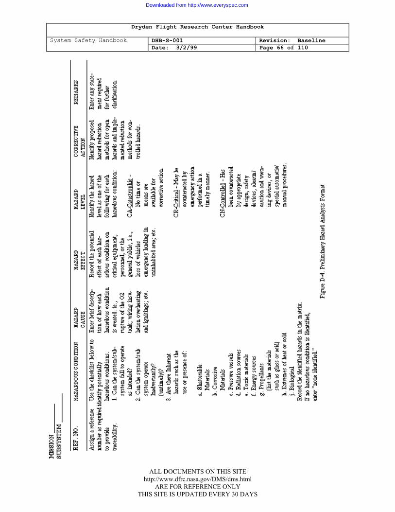
Dryden Flight Research Center Handbook
System Safety Handbook DHB-S-001 Revision: Baseline Date: 3/2/99 Page 66 of 110
ALL DOCUMENTS ON THIS SITE
http://www.dfrc.nasa.gov/DMS/dms.html ARE FOR REFERENCE ONLY
THIS SITE IS UPDATED EVERY 30 DAYS
Downloaded from http://www.everyspec.com
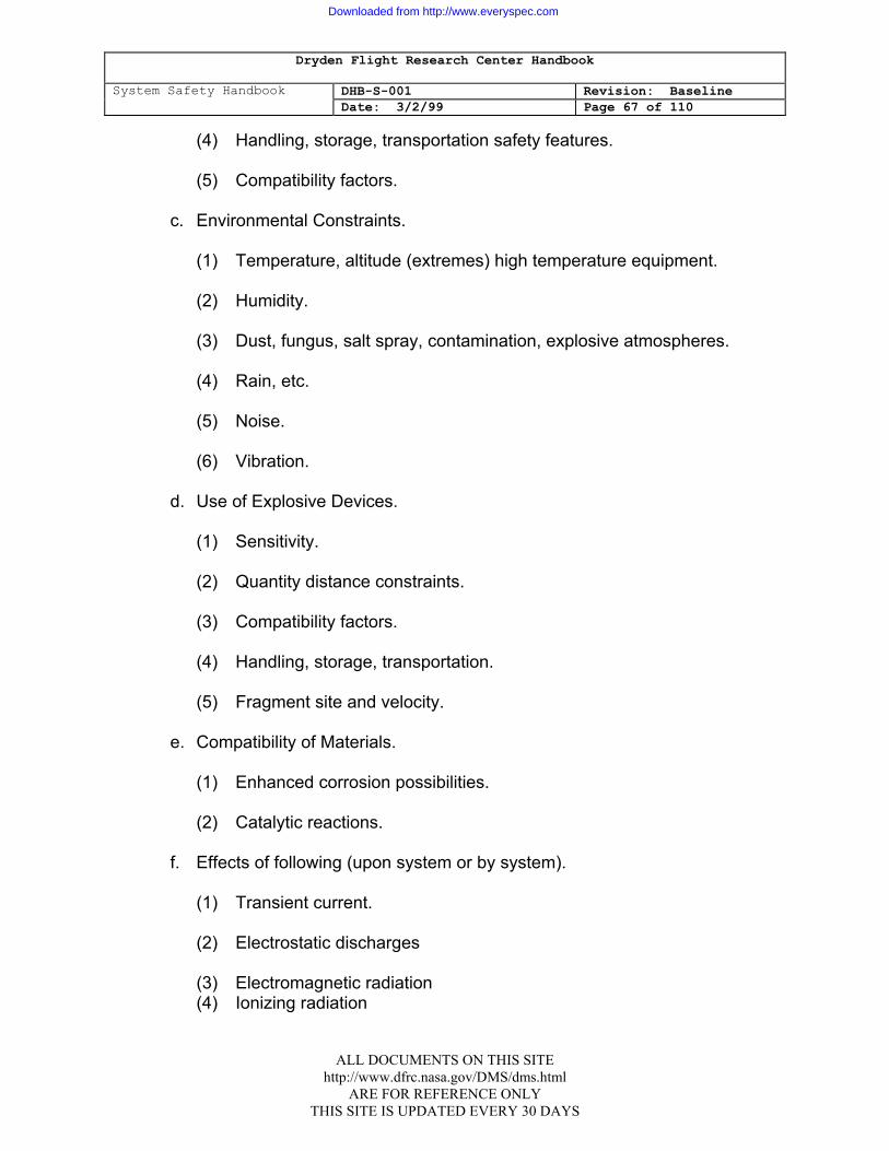
Dryden Flight Research Center Handbook
System Safety Handbook DHB-S-001 Revision: Baseline Date: 3/2/99 Page 67 of 110
(4) Handling, storage, transportation safety features. (5) Compatibility factors.
c. Environmental Constraints.
(1) Temperature, altitude (extremes) high temperature equipment. (2) Humidity. (3) Dust, fungus, salt spray, contamination, explosive atmospheres. (4) Rain, etc. (5) Noise. (6) Vibration.
d. Use of Explosive Devices.
(1) Sensitivity. (2) Quantity distance constraints. (3) Compatibility factors. (4) Handling, storage, transportation. (5) Fragment site and velocity.
e. Compatibility of Materials.
(1) Enhanced corrosion possibilities. (2) Catalytic reactions.
f. Effects of following (upon system or by system).
(1) Transient current. (2) Electrostatic discharges (3) Electromagnetic radiation (4) Ionizing radiation
ALL DOCUMENTS ON THIS SITE http://www.dfrc.nasa.gov/DMS/dms.html
ARE FOR REFERENCE ONLY THIS SITE IS UPDATED EVERY 30 DAYS
Downloaded from http://www.everyspec.com
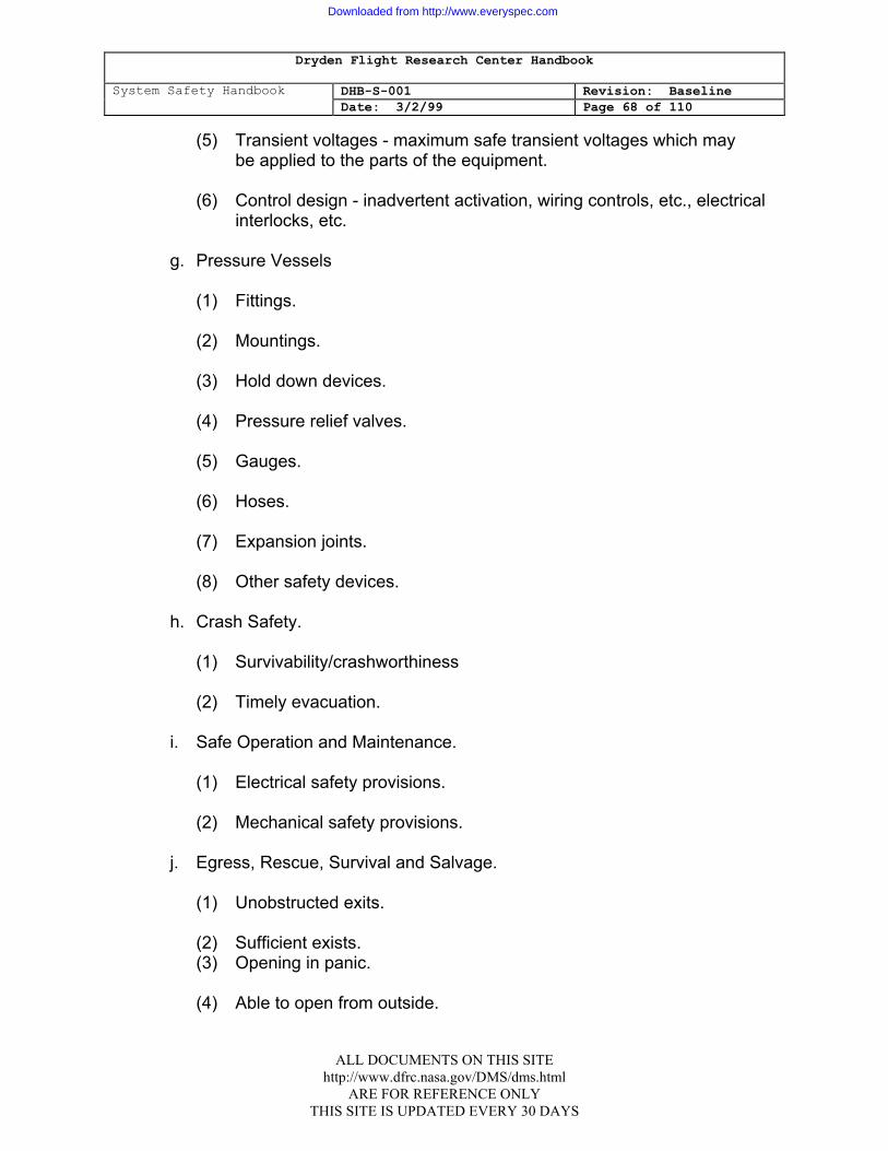
Dryden Flight Research Center Handbook
System Safety Handbook DHB-S-001 Revision: Baseline Date: 3/2/99 Page 68 of 110
(5) Transient voltages - maximum safe transient voltages which may be applied to the parts of the equipment. (6) Control design - inadvertent activation, wiring controls, etc., electrical
interlocks, etc.
g. Pressure Vessels
(1) Fittings. (2) Mountings. (3) Hold down devices. (4) Pressure relief valves. (5) Gauges. (6) Hoses. (7) Expansion joints. (8) Other safety devices.
h. Crash Safety.
(1) Survivability/crashworthiness (2) Timely evacuation.
i. Safe Operation and Maintenance.
(1) Electrical safety provisions.
(2) Mechanical safety provisions.
j. Egress, Rescue, Survival and Salvage.
(1) Unobstructed exits.
(2) Sufficient exists. (3) Opening in panic. (4) Able to open from outside.
ALL DOCUMENTS ON THIS SITE http://www.dfrc.nasa.gov/DMS/dms.html
ARE FOR REFERENCE ONLY THIS SITE IS UPDATED EVERY 30 DAYS
Downloaded from http://www.everyspec.com
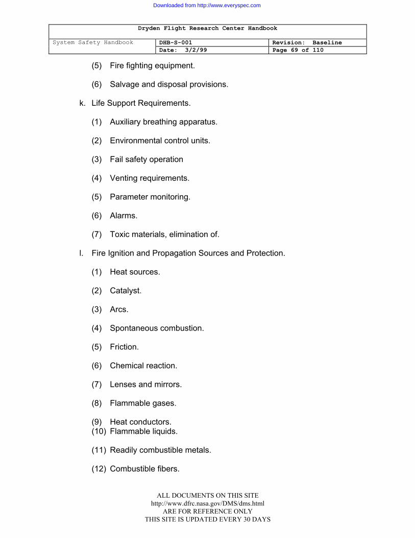
Dryden Flight Research Center Handbook
System Safety Handbook DHB-S-001 Revision: Baseline Date: 3/2/99 Page 69 of 110
(5) Fire fighting equipment. (6) Salvage and disposal provisions.
k. Life Support Requirements.
(1) Auxiliary breathing apparatus. (2) Environmental control units. (3) Fail safety operation (4) Venting requirements. (5) Parameter monitoring. (6) Alarms.
(7) Toxic materials, elimination of.
l. Fire Ignition and Propagation Sources and Protection.
(1) Heat sources. (2) Catalyst. (3) Arcs. (4) Spontaneous combustion. (5) Friction. (6) Chemical reaction. (7) Lenses and mirrors. (8) Flammable gases. (9) Heat conductors. (10) Flammable liquids. (11) Readily combustible metals. (12) Combustible fibers.
ALL DOCUMENTS ON THIS SITE http://www.dfrc.nasa.gov/DMS/dms.html
ARE FOR REFERENCE ONLY THIS SITE IS UPDATED EVERY 30 DAYS
Downloaded from http://www.everyspec.com
Dryden Flight Research Center Handbook
System Safety Handbook DHB-S-001 Revision: Baseline Date: 3/2/99 Page 70 of 110
(13) Plastics - toxic gases evolved during combustion. (14) Automatic fire extinguishing equipment.
m. Resistance to Shock Damage.
n. Human Factors and Ergonometric Factors.
(1) Work space - dimensions. (2) Posture of maintenance personnel. (3) Lifting provision. (4) Visual acquity requirements. (5) Glare Control (6) Control illumination.
o. Fail Safe Design Considerations.
(1) Fusing. (2) Automatic shutdown. (3) Interlocks. (4) Power sequencing.
p. Vulnerability and Survivability.
(1) Personnel armor. (2) Equipment armor. (3) Redundancy. (4) Dependence on the system.
q. Protective Clothing, Equipment or Devices.
(1) Respirator. (2) Flame-proof clothing.
ALL DOCUMENTS ON THIS SITE http://www.dfrc.nasa.gov/DMS/dms.html
ARE FOR REFERENCE ONLY THIS SITE IS UPDATED EVERY 30 DAYS
Downloaded from http://www.everyspec.com
Dryden Flight Research Center Handbook
System Safety Handbook DHB-S-001 Revision: Baseline Date: 3/2/99 Page 71 of 110
(3) Gloves (4) Goggles/safety glasses. (5) Thermal clothing.
r. Lightning and Electrostatic Protection.
(1) Grounding rods and networks. (2) Electrostatic collection electrodes. (3) High current ground conductors for lightning towers, antennas,
shelters. (4) Electrostatic voltage controls for input/output leads, and power lines.
s. Human Error Analysis of Operator Functions, Tasks, Software, and
Requirements.
(1) Error reducing design. (2) Task assignment. (3) Results of operator error (4) Improper sequencing. (5) Use of automatic sequencing and control. (6) Use of software controlling hardware.
ALL DOCUMENTS ON THIS SITE http://www.dfrc.nasa.gov/DMS/dms.html
ARE FOR REFERENCE ONLY THIS SITE IS UPDATED EVERY 30 DAYS
Downloaded from http://www.everyspec.com
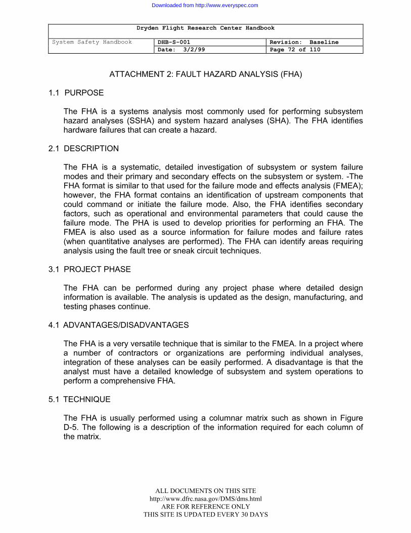
Dryden Flight Research Center Handbook
System Safety Handbook DHB-S-001 Revision: Baseline Date: 3/2/99 Page 72 of 110
ATTACHMENT 2: FAULT HAZARD ANALYSIS (FHA) 1.1 PURPOSE
The FHA is a systems analysis most commonly used for performing subsystem hazard analyses (SSHA) and system hazard analyses (SHA). The FHA identifies hardware failures that can create a hazard.
2.1 DESCRIPTION
The FHA is a systematic, detailed investigation of subsystem or system failure modes and their primary and secondary effects on the subsystem or system. -The FHA format is similar to that used for the failure mode and effects analysis (FMEA); however, the FHA format contains an identification of upstream components that could command or initiate the failure mode. Also, the FHA identifies secondary factors, such as operational and environmental parameters that could cause the failure mode. The PHA is used to develop priorities for performing an FHA. The FMEA is also used as a source information for failure modes and failure rates (when quantitative analyses are performed). The FHA can identify areas requiring analysis using the fault tree or sneak circuit techniques.
3.1 PROJECT PHASE
The FHA can be performed during any project phase where detailed design information is available. The analysis is updated as the design, manufacturing, and testing phases continue.
4.1 ADVANTAGES/DISADVANTAGES
The FHA is a very versatile technique that is similar to the FMEA. In a project where a number of contractors or organizations are performing individual analyses, integration of these analyses can be easily performed. A disadvantage is that the analyst must have a detailed knowledge of subsystem and system operations to perform a comprehensive FHA.
5.1 TECHNIQUE
The FHA is usually performed using a columnar matrix such as shown in Figure D-5. The following is a description of the information required for each column of the matrix.
ALL DOCUMENTS ON THIS SITE http://www.dfrc.nasa.gov/DMS/dms.html
ARE FOR REFERENCE ONLY THIS SITE IS UPDATED EVERY 30 DAYS
Downloaded from http://www.everyspec.com
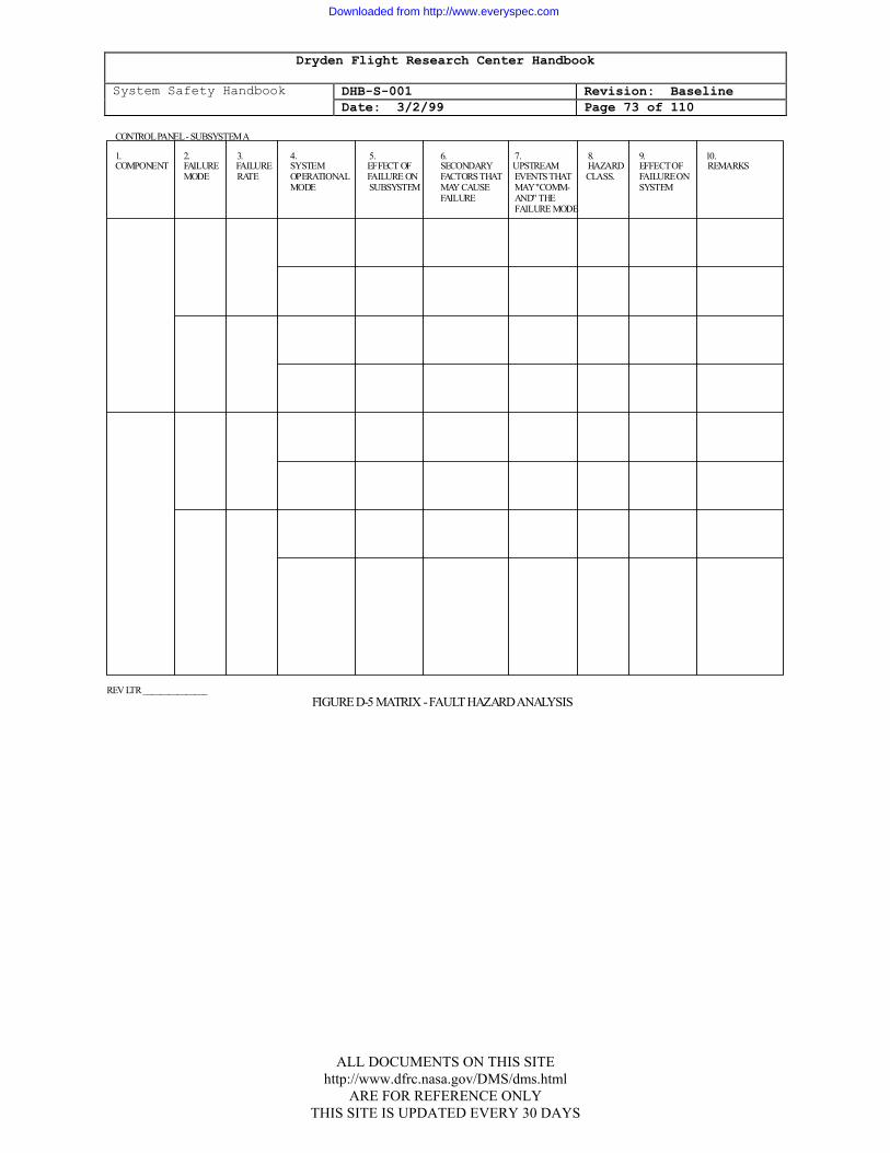
Dryden Flight Research Center Handbook
System Safety Handbook DHB-S-001 Revision: Baseline Date: 3/2/99 Page 73 of 110
CONTROL PANEL - SUBSYSTEM A
1. 2. 3. 4. 5. 6. 7. 8. 9. 10.COMPONENT FAILURE FAILURE SYSTEM EFFECT OF SECONDARY UPSTREAM HAZARD EFFECT OF REMARKS MODE RATE OPERATIONAL FAILURE ON FACTORS THAT EVENTS THAT CLASS. FAILURE ON MODE SUBSYSTEM MAY CAUSE MAY "COMM- SYSTEM FAILURE AND" THE FAILURE MODE
REV LTR _______________ FIGURE D-5 MATRIX - FAULT HAZARD ANALYSIS D-16
ALL DOCUMENTS ON THIS SITE http://www.dfrc.nasa.gov/DMS/dms.html
ARE FOR REFERENCE ONLY THIS SITE IS UPDATED EVERY 30 DAYS
Downloaded from http://www.everyspec.com

Dryden Flight Research Center Handbook
System Safety Handbook DHB-S-001 Revision: Baseline Date: 3/2/99 Page 74 of 110
1. COMPONENT
This column identifies the major functional activity or hardware components within the subsystem being analyzed. The major component should be identified by part number and descriptive title.
2. FAILURE MODE
This column identifies all credible failure modes for the identified major component. The FMEA should supply this information, whenever applicable.
3. FAILURE RATE
When performing quantitative analyses, this column is used to enter a probability of failure estimate of the component in the indicated failure mode. This is the component's primary failure rate. The source of data must be indicated but is normally the FMEA.
4. SYSTEM OPERATIONAL
MODE
This column identifies the system mode of operation in which the major component is operating during the indicated failure mode.
5. EFFECT OF FAILURE ON SUBSYSTEM
This column identifies the direct effect, on the subsystem and components within the subsystem, of the indicated component failure for the indicated system operational mode.
6. SECONDARY FACTORS THAT MAY CAUSE FAILURE
This column identifies the abnormal and out-of-tolerance conditions (generally environmental) which can cause the indicated failure mode under investigation. The specific tolerance limits must be given.
7. UPSTREAM EVENTS THAT MAY "COMMAND" THE FAILURE MODE
This column identifies those functions, events, or failures which directly place the component in the indicated failure mode.
ALL DOCUMENTS ON THIS SITE http://www.dfrc.nasa.gov/DMS/dms.html
ARE FOR REFERENCE ONLY THIS SITE IS UPDATED EVERY 30 DAYS
Downloaded from http://www.everyspec.com
Dryden Flight Research Center Handbook
System Safety Handbook DHB-S-001 Revision: Baseline Date: 3/2/99 Page 75 of 110
8. HAZARD CLASSIFICATION
This column provides a qualitative measure of significance for the indicated potential effect (column 5) of each identified component failure mode.
9. EFFECT OF FAILURE, ON SYSTEM
This column identifies the direct effect of the component failure on the system when in the indicated system operational mode. Note that this column is used only when full system knowledge is available.
10. REMARKS
This column provides for any additional information which may be pertinent to the analysis and is normally used to identify the recommended and actual means of hazard control.
ALL DOCUMENTS ON THIS SITE http://www.dfrc.nasa.gov/DMS/dms.html
ARE FOR REFERENCE ONLY THIS SITE IS UPDATED EVERY 30 DAYS
Downloaded from http://www.everyspec.com

Dryden Flight Research Center Handbook
System Safety Handbook DHB-S-001 Revision: Baseline Date: 3/2/99 Page 76 of 110
ATTACHMENT 3: OPERATING AND SUPPORT HAZARD ANALYSIS (O&SHA) 1.1 PURPOSE
The purpose of the O&SHA is to ensure the evaluation of all man-machine elements and automatic unmanned operations. associated with the project. This includes the evaluation of procedures and tasks associated with production, installation, maintenance, testing , modification, transportation, operation, storage, training, and disposal.
2.1 DESCRIPTION
The O&SHA is used to examine procedurally controlled activities to identify and evaluate hazards resulting from the implementation of operations or tasks performed by persons. It must consider the planned system configuration at each phase of activity; the facility interfaces; the planned environments; the supporting tools or other equipment specified for use; operational/task sequence, concurrent task effects and limitations; biotechnological factors, regulatory or contractually specified personnel safety and health requirements; and the potential for unplanned events including hazards introduced by human efforts. Using the results of the PHA, SSHA, and SHA, the O&SHA identifies hazardous operations and tasks, the hazardous .conditions associated with the tasks, the causes of the hazardous conditions, the risks associated with the hazardous conditions, and recommendations to eliminate or reduce the effects of the hazardous conditions.. Data required to perform the O&SHA are drawings, specifications, timelines, procedures, schematics, and other hazard analyses such as the PHA, SSHA, and SHA. Operational scenarios should be developed to aid in the performance of the O&SHA.
3.1 PROJECT PHASE
The O&SHA is initiated as soon as practicable in the development phase of the project. If a general timeline for operations can be developed, the O&SHA can be started. This could be as early as the conceptual phase of the project. The-analysis must be updated and performed in more detail as specific procedures are developed.
4.1 ADVANTAGES/DISADVANTAGES
The O&SHA technique is easily learned and provides safety data on procedures that are not directly derived from other analysis techniques. If the analysis is not performed early in the project development, it cannot easily affect the. design. Historically, the 0&SHA has been performed only after procedures are developed.
ALL DOCUMENTS ON THIS SITE http://www.dfrc.nasa.gov/DMS/dms.html
ARE FOR REFERENCE ONLY THIS SITE IS UPDATED EVERY 30 DAYS
Downloaded from http://www.everyspec.com
Dryden Flight Research Center Handbook
System Safety Handbook DHB-S-001 Revision: Baseline Date: 3/2/99 Page 77 of 110
The only viable recommendations at this time are minor procedural changes and the insertion of caution and warning notes in the procedure.
5.1 TECHNIQUE
The O&SHA is usually performed using a columnar matrix format such as shown in Figure D-6. The following is a description of each column of the matrix: 1. SPECIFIC TASK OR GENERAL OPERATION This column is used to identify and describe each operation, task, or procedure
to the lowest level of detail possible to analyze the associated hazards. The cases where operations have not been defined, assumptions should be made to facilitate the analysis; however, the assumptions should be-noted as such.
2. PHASE, MODE, FUNCTION This column is used to identify the phase, mode, or function of the operation
under analysis. This generally provides useful information necessary in identifying hazards.
3. CRITERIA, CONSTRAINTS, ENERGY SOURCES This column is used to identify pertinent criteria and constraints of the operation
under analysis which may affect safety (for example, the particular magnitude of voltage, current, pressure, radar frequency, etc.). It is also used to identify the presence and magnitude of any energy sources, such as propellants, explosives, velocity, etc. Generally speaking, this column is used to identify hazardous elements.
4. HAZARDOUS CONDITIONS AND THEIR IMPACT This column is used to identify hazardous conditions involved in the operation
under analysis and the potential impact or effect of the hazardous conditions. 5. HAZARD CLASSIFICATION This column provides a qualitative measure of the risk assessment of each
identified hazardous condition.
ALL DOCUMENTS ON THIS SITE http://www.dfrc.nasa.gov/DMS/dms.html
ARE FOR REFERENCE ONLY THIS SITE IS UPDATED EVERY 30 DAYS
Downloaded from http://www.everyspec.com
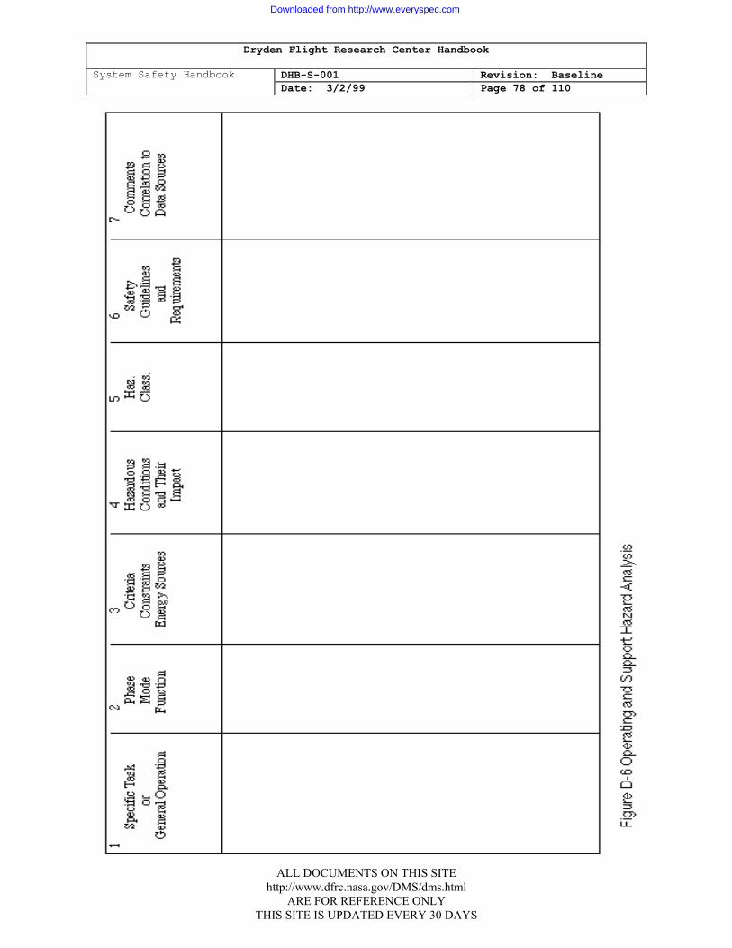
Dryden Flight Research Center Handbook
System Safety Handbook DHB-S-001 Revision: Baseline Date: 3/2/99 Page 78 of 110
ALL DOCUMENTS ON THIS SITE http://www.dfrc.nasa.gov/DMS/dms.html
ARE FOR REFERENCE ONLY THIS SITE IS UPDATED EVERY 30 DAYS
Downloaded from http://www.everyspec.com
Dryden Flight Research Center Handbook
System Safety Handbook DHB-S-001 Revision: Baseline Date: 3/2/99 Page 79 of 110
6. SAFETY GUIDELINES AND REQUIREMENTS This column is used to establish recommended preventive measures for
eliminating or controlling the identified hazardous conditions. These recommendations may take the form of guidelines, requirements, further analysis, etc.
7. COMMENTS, CORRELATION TO DATA SOURCES This column is used to record information pertinent to the analysis which may
facilitate tracking the analysis at a later date. Design drawing and. data used, source or derivation of requirements, calculations, and concepts should be included. Also, key comments or ideas of the analyst should be recorded.
ALL DOCUMENTS ON THIS SITE http://www.dfrc.nasa.gov/DMS/dms.html
ARE FOR REFERENCE ONLY THIS SITE IS UPDATED EVERY 30 DAYS
Downloaded from http://www.everyspec.com
Dryden Flight Research Center Handbook
System Safety Handbook DHB-S-001 Revision: Baseline Date: 3/2/99 Page 80 of 110
ATTACHMENT 4: FAULT TREE ANALYSIS (FTA)
1.1 PURPOSE
1. The FTA is a deductive analytical technique which lends itself to detailed systems analysis, decision making, and communication. When used as a system safety analysis tool, the fault tree results in a graphic and logical representation of the various combinations of possible events, both fault and normal, occurring within a system, which can cause a pre-defined undesired event. An Undesired event is any event which is identified as Objectionable and unwanted, such as a potential accident or hazardous condition. This graphic presentation exposes the interrelationships of system events and their dependence upon each other, which may result in the occurrence of the undesired event.
2. When the fault tree structure is completed, an evaluation of the fault tree is
performed to determine the results or significance of the analysis. Two types of evaluations' are possible, qualitative and quantitative. The qualitative evaluation is an engineering judgment assessment of the fault tree. The quantitative evaluation is a numerical evaluation. Failure rates of the system elements are Inserted into the fault tree structure and mathematically combined to yield probabilities. The validity of action taken to eliminate or control fault events can be enhanced in certain circumstances by. quantifying the fault tree and performing such a numerical evaluation. The quantification and numerical evaluation may provide three basic measurements for decision making relative to risk acceptability and required preventive measures. They are:
a. The probability of occurrence of the undesired event;
b. The significance or importance of the undesired event or the various paths
leading to the undesired event; c. A baseline measure of the level of safety, which can be used to determine
the effect of design changes.
3. As recommended preventive measures are incorporated into the design, their adequacy involving the safety problem may be verified. This is done by making the appropriate changes in the fault tree structure and then reevaluating the fault tree. The effects of the change, or the relative measure of improvement., should be apparent from the re-evaluation.
ALL DOCUMENTS ON THIS SITE http://www.dfrc.nasa.gov/DMS/dms.html
ARE FOR REFERENCE ONLY THIS SITE IS UPDATED EVERY 30 DAYS
Downloaded from http://www.everyspec.com
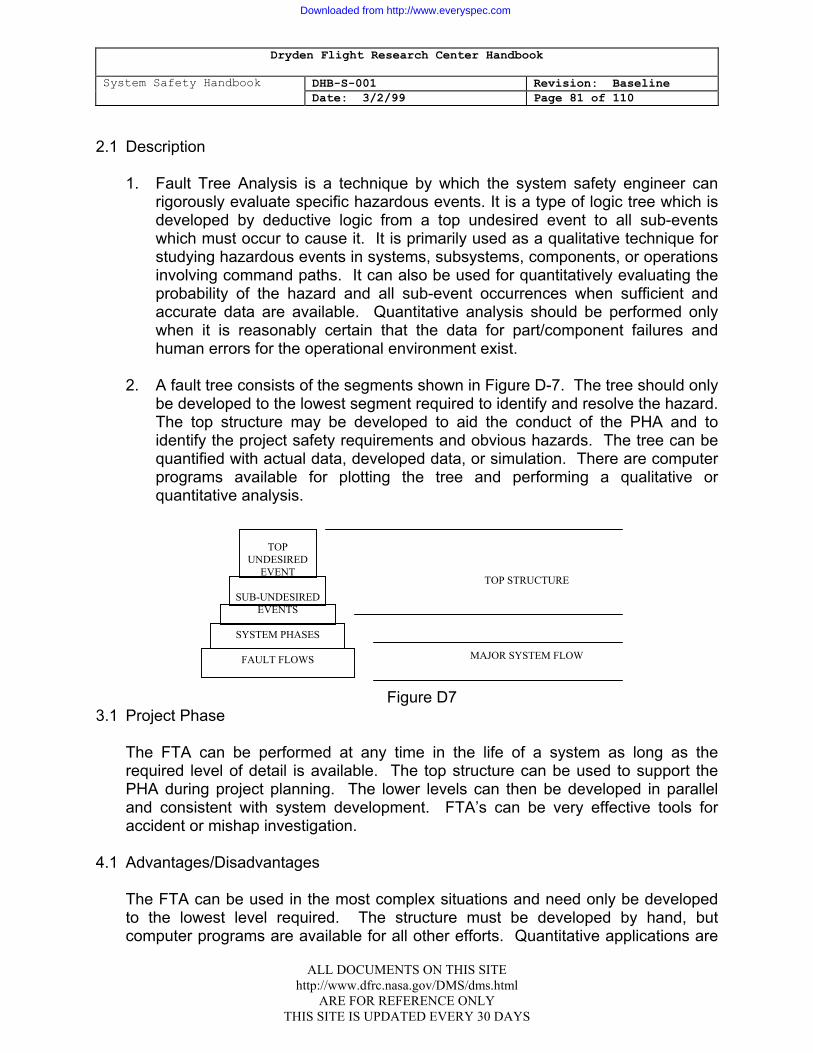
Dryden Flight Research Center Handbook
System Safety Handbook DHB-S-001 Revision: Baseline Date: 3/2/99 Page 81 of 110
2.1 Description
1. Fault Tree Analysis is a technique by which the system safety engineer can
rigorously evaluate specific hazardous events. It is a type of logic tree which is developed by deductive logic from a top undesired event to all sub-events which must occur to cause it. It is primarily used as a qualitative technique for studying hazardous events in systems, subsystems, components, or operations involving command paths. It can also be used for quantitatively evaluating the probability of the hazard and all sub-event occurrences when sufficient and accurate data are available. Quantitative analysis should be performed only when it is reasonably certain that the data for part/component failures and human errors for the operational environment exist.
2. A fault tree consists of the segments shown in Figure D-7. The tree should only be developed to the lowest segment required to identify and resolve the hazard. The top structure may be developed to aid the conduct of the PHA and to identify the project safety requirements and obvious hazards. The tree can be quantified with actual data, developed data, or simulation. There are computer programs available for plotting the tree and performing a qualitative or quantitative analysis.
Figure D7
TOP STRUCTURE
MAJOR SYSTEM FLOW
SUBSYSTEM FLOW AND
TOP UNDESIRED
EVENT
SUB-UNDESIRED EVENTS
SYSTEM PHASES
FAULT FLOWS
BASIC EVENTS
3.1 Project Phase
The FTA can be performed at any time in the life of a system as long as the required level of detail is available. The top structure can be used to support the PHA during project planning. The lower levels can then be developed in parallel and consistent with system development. FTA’s can be very effective tools for accident or mishap investigation.
4.1 Advantages/Disadvantages
The FTA can be used in the most complex situations and need only be developed to the lowest level required. The structure must be developed by hand, but computer programs are available for all other efforts. Quantitative applications are
ALL DOCUMENTS ON THIS SITE http://www.dfrc.nasa.gov/DMS/dms.html
ARE FOR REFERENCE ONLY THIS SITE IS UPDATED EVERY 30 DAYS
Downloaded from http://www.everyspec.com
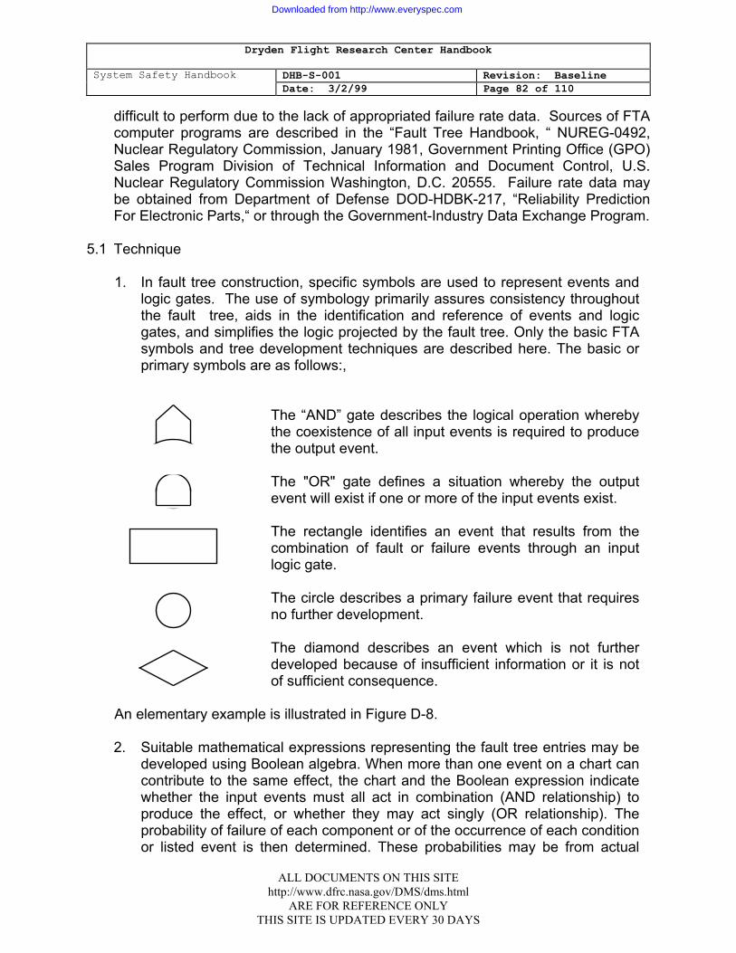
Dryden Flight Research Center Handbook
System Safety Handbook DHB-S-001 Revision: Baseline Date: 3/2/99 Page 82 of 110
difficult to perform due to the lack of appropriated failure rate data. Sources of FTA computer programs are described in the “Fault Tree Handbook, “ NUREG-0492, Nuclear Regulatory Commission, January 1981, Government Printing Office (GPO) Sales Program Division of Technical Information and Document Control, U.S. Nuclear Regulatory Commission Washington, D.C. 20555. Failure rate data may be obtained from Department of Defense DOD-HDBK-217, “Reliability Prediction For Electronic Parts,“ or through the Government-Industry Data Exchange Program.
5.1 Technique
1. In fault tree construction, specific symbols are used to represent events and logic gates. The use of symbology primarily assures consistency throughout the fault tree, aids in the identification and reference of events and logic gates, and simplifies the logic projected by the fault tree. Only the basic FTA symbols and tree development techniques are described here. The basic or primary symbols are as follows:,
The “AND” gate describes the logical operation whereby the coexistence of all input events is required to produce the output event.
The "OR" gate defines a situation whereby the output event will exist if one or more of the input events exist.
The rectangle identifies an event that results from the combination of fault or failure events through an input logic gate.
The circle describes a primary failure event that requires no further development.
The diamond describes an event which is not further developed because of insufficient information or it is not of sufficient consequence.
An elementary example is illustrated in Figure D-8. 2. Suitable mathematical expressions representing the fault tree entries may be
developed using Boolean algebra. When more than one event on a chart can contribute to the same effect, the chart and the Boolean expression indicate whether the input events must all act in combination (AND relationship) to produce the effect, or whether they may act singly (OR relationship). The probability of failure of each component or of the occurrence of each condition or listed event is then determined. These probabilities may be from actual
ALL DOCUMENTS ON THIS SITE http://www.dfrc.nasa.gov/DMS/dms.html
ARE FOR REFERENCE ONLY THIS SITE IS UPDATED EVERY 30 DAYS
Downloaded from http://www.everyspec.com

Dryden Flight Research Center Handbook
System Safety Handbook DHB-S-001 Revision: Baseline Date: 3/2/99 Page 83 of 110
failure rates; vendors test data; comparison with similar equipment, events, or conditions; or experimental data obtained specifically for the system. The probabilities are then entered into the simplified Boolean expressions. The probability of occurrence of the undesirable event being investigated may then be determined by calculation. When an FTA is used for qualitative analysis, care is required in the description of each event to be sure it can be fitted with a suitable probability.
FUSE FAILS TO OPEN
EXCESSIVE CURRENT IN
CIRCUIT
EXCESSIVE CURRENT THROUGH
MOTOR
PRIMARY MOTOR
FAILURE (OVER-
HEATED)
PRIMARY FUSE
FAILURE (CLOSED)
PRIMARY POWER
FAILURE
PRIMARY WIRING
FAILURE (SHORTED)
B
C
A
MOTOR OVERHEATS
Figure D-8 Sample System Fault Tree
ALL DOCUMENTS ON THIS SITE http://www.dfrc.nasa.gov/DMS/dms.html
ARE FOR REFERENCE ONLY THIS SITE IS UPDATED EVERY 30 DAYS
Downloaded from http://www.everyspec.com
Dryden Flight Research Center Handbook
System Safety Handbook DHB-S-001 Revision: Baseline Date: 3/2/99 Page 84 of 110
ATTACHMENT 5: COMMON CAUSE FAILURE ANALYSIS (CCFA) 1.1 PURPOSE
1. A CCFA is utilized to determine if there are combined multiple failures of.
components and operator errors which result in degradation or disablement of a system and are set up by a common event or causative mechanism.
2. Common cause failures can affect redundant and interlocked design features in
the system. when redundancy is provided by identical components, locations, or -channels, susceptibility to common cause failures may be, increased. For example, susceptibility of redundant systems due to identical locations is seen when fire can burn away insulation of collocated wire bundles such that the wires short together and render inoperative a primary system and its backup.
3. Common cause failures need not occur simultaneously. Generally, they should
be considered to coexist prior to maintenance checks or other procedures which might reasonably be expected to discover any part of the failure.
2.1 DESCRIPTION
The CFA, in general, is an extension of the Fault Tree Analysis. Its emphasis is directed toward the identification of multiple failures that may result from a single cause or event. These single secondary cause/events may result from a ..common process, manufacturing defect, a common human operator error, or. some common external event. The analysis will identify the possible interaction of failures in independent redundant systems. Experience has shown that there is a finite list of common causes or events which should be checked. These typically deal with physical location and manufacturing characteristics such as common subjected environments, wire routing through a common connector or tray, common design processes which introduce a generic defect during manufacture, or susceptibility to common calibration errors- because a defective instrument (or procedure) was used !during installation or maintenance.
3.1 PROJECT PHASE
Functional level CCFA's should be performed early in the project phase to identify critical items for design consideration. Detailed or component level CCFA's can be performed only after the detailed design is completed.
ALL DOCUMENTS ON THIS SITE http://www.dfrc.nasa.gov/DMS/dms.html
ARE FOR REFERENCE ONLY THIS SITE IS UPDATED EVERY 30 DAYS
Downloaded from http://www.everyspec.com
Dryden Flight Research Center Handbook
System Safety Handbook DHB-S-001 Revision: Baseline Date: 3/2/99 Page 85 of 110
4.1 ADVANTAGE/DISADVANTAGES
CCFA's offer advantages over other analyses in situations where a single causative factor results in failure of interactive systems or components, which may or may not be redundant. The procedure offers a highly organized approach for assessing potential common cause failures in complex electrical/electronic systems. A computer aided system is required for complex systems.
5.1 TECHNIQUE
1 . The overall task flow begins with the development or collection of topological network trees for the electrical portions of 'a control system. The trees are segregated for various. analytical tasks according to concerns evidenced in a top-level qualitative fault tree. Those trees which are- found to have significant system interdependency or redundancy are subjected to Common Cause Hazard Analysis (CCHA) at the Lowest Replaceable Unit (LRU) or piece-part level.
2. The CCFA is prepared with checklists, much like a Preliminary Hazard
Analysis. The first check made on a group of interdependent/ redundant trees is to identify commonalties. The checklist for commonality identification can be tailored according to project, application boundaries, or experience. Generally, it appears as follows:
a. Commonality checklist.
(1) Location and environment. (a) Chassis. (b) Packaging/containment. (c) Elevation. (2) Manufacture. (a) Part numbers. (b) Equipment name/item. (c) Process. (d) Calibration/test. (3) Maintenance
ALL DOCUMENTS ON THIS SITE http://www.dfrc.nasa.gov/DMS/dms.html
ARE FOR REFERENCE ONLY THIS SITE IS UPDATED EVERY 30 DAYS
Downloaded from http://www.everyspec.com
Dryden Flight Research Center Handbook
System Safety Handbook DHB-S-001 Revision: Baseline Date: 3/2/99 Page 86 of 110
(a) Period. (b) Calibration equipment. (c) Personnel. (d) Materials. (4) Operations. (a) Status displays. (b) Inputs.
Other entries such as TRANSPORTATION and INSTALLATION can be made. Sub-entries can be expanded, such as by adding THERMAL (COLD/HEAT),
EXPOSURE, HUMIDITY and VIBRATION to the ENVIRONMENT checks. Likewise, the sub-entries can be expanded where necessary. For example, the ELEVATION item can involve checks for ATMOSPHERIC PRESSURE/ CORONA or FLOODING.
b. For each commonality found, a second checklist is used to correlate
possible, critical conditions of the tree. group within the area of commonality. The critical condition checklist is of the following form:
(1) Electrical.
(a) Short.
(b) Open.
(c) Clocking.
(2) Mechanical.
(a) Separation/shock. (b) Welding.
(c) Obstruction.
(3) Chemical, corrosives.
ALL DOCUMENTS ON THIS SITE http://www.dfrc.nasa.gov/DMS/dms.html
ARE FOR REFERENCE ONLY THIS SITE IS UPDATED EVERY 30 DAYS
Downloaded from http://www.everyspec.com
Dryden Flight Research Center Handbook
System Safety Handbook DHB-S-001 Revision: Baseline Date: 3/2/99 Page 87 of 110
(4) Biological.
c. The next step in the process is to apply a third checklist to suggest credible accident-initiating events, mechanisms, or causes. At this point, it should be realized that not every possible cause of a critical accident need be predetermined. There is no need to identify all contributing scenarios if a single credible cause of a critical accident can be foreseen. Corrective action should be instituted to prohibit design susceptibility for the whole class of conditions due to. any trigger event. Therefore, the third checklist represents a search for a credible trigger event scenario:
(1) Conductive contaminant. (2) Mechanical shearing. (3) Fire/explosion. (4) Flood. (5) Loss of cooling. (6) Dust/grit.
d. Again, each entry can be broken down. For example, CONDUCTIVE
CONTAMINANT can represent FLUIDS (salt water and acid) and METALTRIMMINGS. Sources for each trigger event can also be postulated with a fourth checklist, if desired, but this is usually unnecessary.
3. As with any analytical effort, no useful result is produced unless each significant
activity is documented. Results must be recorded and tracked through appropriate resolution, otherwise, something may be overlooked or the corrective action may introduce a worse situation. Any kind of tracking form can be used to document the coverage of the effort, but significant hazards with their associated accident scenarios generally should be separately reported, illustrated, numbered, and tracked as high-risk items.
4. The approach to Common Cause Failure Analysis is shown in Figure D-9. The
effort is performed in four steps. First, all common elements within the trees of each group are identified and listed. These commonalties may be shared connectors; common locations in terms of modules, cabinets, or wire bundles; or more generic features, such as common manufacturer or other
ALL DOCUMENTS ON THIS SITE http://www.dfrc.nasa.gov/DMS/dms.html
ARE FOR REFERENCE ONLY THIS SITE IS UPDATED EVERY 30 DAYS
Downloaded from http://www.everyspec.com
Dryden Flight Research Center Handbook
System Safety Handbook DHB-S-001 Revision: Baseline Date: 3/2/99 Page 88 of 110
characteristics. The second step is to determine the credible failure modes of piece parts identified from the first step. Examples of failure modes might be electrical shorts, electrical opens, maintenance errors and calibration errors. The third step requires documentation of at least one credible cause of each failure mode identified in the second step. It is not 'productive to try to' list all possible causes of such failure modes, but listing at least one credible initiating event should suffice to show the need for design improvement. Comprehensive risk assessment may vary widely with each particular trigger mechanism that is suggested. Any resulting design modification should obviate the functional susceptibility to similar causes. Examples of the causes to be listed in the third step would be conductive contaminants, overheat, fire, floods, or other mechanisms which could cause. the electrical shorts, opens, maintenance errors and calibration errors. The last 'step of this procedure is to describe the failure effects and recovery methods for the items listed in step 1. This is documented on a form for subsequent tracking, risk assessment, and resolution as illustrated in Figure D-10.
ALL DOCUMENTS ON THIS SITE http://www.dfrc.nasa.gov/DMS/dms.html
ARE FOR REFERENCE ONLY THIS SITE IS UPDATED EVERY 30 DAYS
Downloaded from http://www.everyspec.com
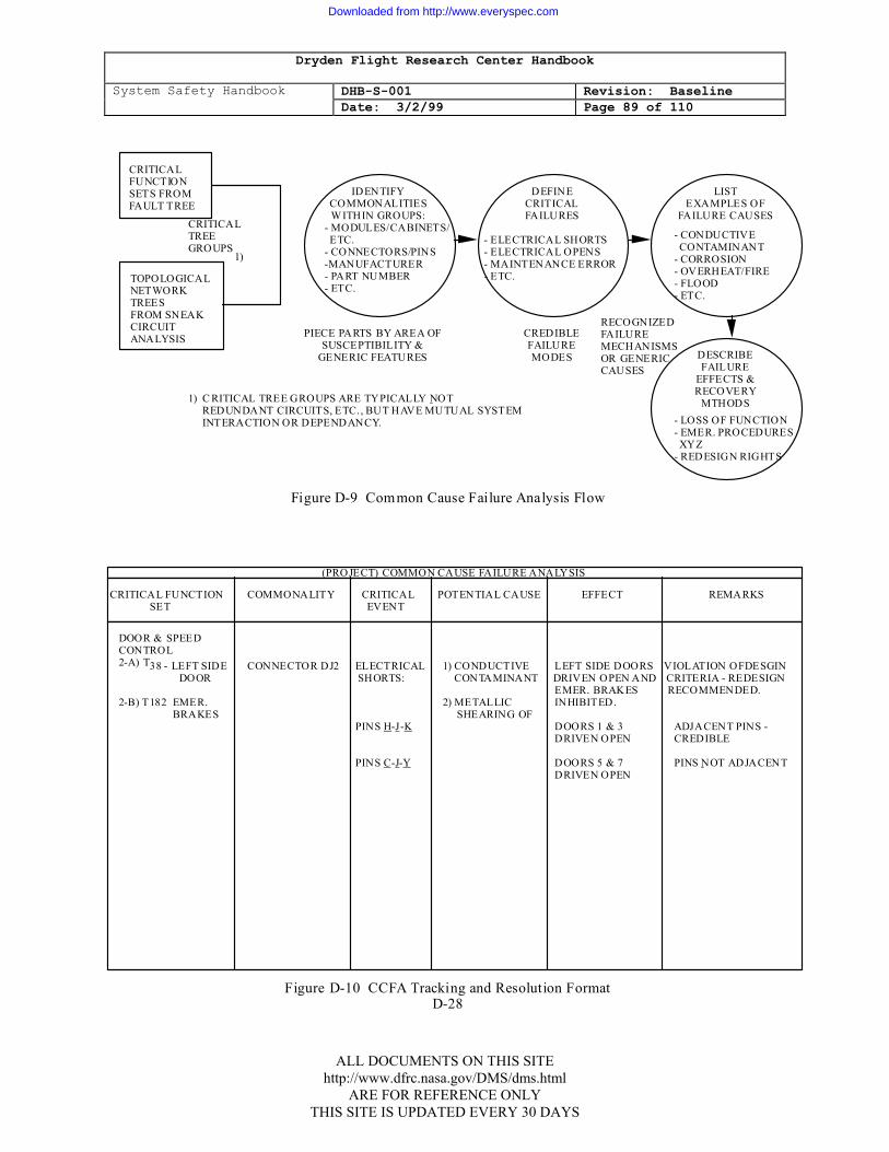
Dryden Flight Research Center Handbook
System Safety Handbook DHB-S-001 Revision: Baseline Date: 3/2/99 Page 89 of 110
CRITICAL FUNCTION SETS FROM FAULT TREE
TOPOLOGICAL NETWORK TREES FROM SNEAK CIRCUIT ANALYSIS
CRITICAL TREE GROUPS
1)
IDENTIFY COMMONALITIES WITHIN GROUPS:
- MODULES/CABINETS/ ETC. - CONNECTORS/PINS -MANUFACTURER - PART NUMBER - ETC.
DEFINE CRITICAL FAILURES
- ELECTRICAL SHORTS - ELECTRICAL OPENS - MAINTENANCE ERROR - ETC.
LIST EXAMPLES OF
FAILURE CAUSES
- CONDUCTIVE CONTAMINANT - CORROSION - OVERHEAT/FIRE - FLOOD - ETC.
DESCRIBE FAILURE
EFFECTS & RECOVERY
MTHODS- LOSS OF FUNCTION - EMER. PROCEDURES XYZ - REDESIGN RIGHTS
RECOGNIZED FAILURE MECHANISMS OR GENERIC CAUSES
PIECE PARTS BY AREA OF SUSCEPTIBILITY &
GENERIC FEATURES
CREDIBLE FAILURE MODES
1) C RITICAL TREE GROUPS ARE TYPICALLY NOT REDUNDANT CIRCUITS, ETC. , BUT HAVE MUTUAL SYSTEM INTERACTION OR DEPENDANCY.
Figure D-9 Common Cause Failure Analysis Flow
(PROJECT) COMMON CAUSE FAILURE ANALYSIS
CRITICAL FUNCTION COMMONALITY CRITICAL POTENTIAL CAUSE EFFECT REMARKS SET EVENT
DOOR & SPEED CONTROL 2-A) T38 - LEFT SIDE CONNECTOR DJ2 ELECTRICAL 1) CONDUCTIVE LEFT SIDE DOORS VIOLATION OFDESGIN DOOR SHORTS: CONTAMINANT DRIVEN OPEN AND CRITERIA - REDESIGN EMER. BRAKES RECOMMENDED. 2-B) T182 EMER. 2) METALLIC INHIBITED. BRAKES SHEARING OF PINS H-J-K DOORS 1 & 3 ADJACENT PINS - DRIVEN OPEN CREDIBLE PINS C-J-Y DOORS 5 & 7 PINS NOT ADJACENT DRIVEN OPEN
Figure D-10 CCFA Tracking and Resolution Format D-28
ALL DOCUMENTS ON THIS SITE http://www.dfrc.nasa.gov/DMS/dms.html
ARE FOR REFERENCE ONLY THIS SITE IS UPDATED EVERY 30 DAYS
Downloaded from http://www.everyspec.com
Dryden Flight Research Center Handbook
System Safety Handbook DHB-S-001 Revision: Baseline Date: 3/2/99 Page 90 of 110
ATTACHMENT 6: SNEAK CIRCUIT ANALYSIS (SCA)
1.1 PURPOSE An SCA is performed to identify areas where undesired functions could occur or
desired functions could be inhibited during normal or off normal operations. 2.1 DESCRIPTION A sneak is defined as an unexpected path or logic flow within a system which,
under certain circumstances, can initiate an undesired function or inhibit a desired function. The path may be influenced by operator actions, and it may consist of hardware, software, fluid flows, or combinations of these elements. A computer-aided analysis approach is necessary for large-scale, complex systems. The computer-aided methods provide for automated development of network trees developed from circuit diagrams. Network trees can be easily analyzed for sneak conditions by using a checklist of clues applied at each junction or decision point.
3.1 PROJECT PHASES Sneak Circuit Analysis should be initiated when component level data are made
available. The preferred start time is prior to the critical design review in the full-scale engineering development phase. Sneak analysis of subsequent data releases and changes should be maintained.
4.1 ADVANTAGES/DISADVANTAGES The Sneak Circuit Analysis technique is a formalized, rigorous, and orderly process
of analytically. assuring that unintended conditions have been excluded from the system. It complements, but does not replace or supersede testing and the common design analysis techniques such as the FMECA (Failure Mode Effects and Criticality Analysis) and FHA. The performance of the SCA can require a significant percentage of the total assurance budget. Therefore, SCA should only be performed on safety critical systems as identified by FMECA or FHA.
5.1 TECHNIQUE
1. SCA is a unique approach to discovery of latent conditions which cause unwanted functions to occur or which inhibit wanted functions, independent of component failure. The technique involves accumulation of detail circuit diagrams and wire lists, arrangement of circuit elements into topological network. trees, and examination of these network trees for suspected sneak circuits.
2. The data used for SCA must represent the system circuitry as it actually is or will be constructed, contingent upon quality control checks, tests, and inspections.
ALL DOCUMENTS ON THIS SITE http://www.dfrc.nasa.gov/DMS/dms.html
ARE FOR REFERENCE ONLY THIS SITE IS UPDATED EVERY 30 DAYS
Downloaded from http://www.everyspec.com
Dryden Flight Research Center Handbook
System Safety Handbook DHB-S-001 Revision: Baseline Date: 3/2/99 Page 91 of 110
All reports are written against these drawings. An analysis based on the detailed circuit drawings identifies more system conditions than an analysis performed using system or functional level schematics. The higher level drawings frequently represent design intent or a perception of intended system design. The process of translating this design into detailed schematics and wire lists typically results in latent sneak conditions. For this reason, analysis only at the higher level involves a risk that not all of the problems will be found.
3. In early program development phases, detailed drawings are not available and
the system level drawings must be used for the analysis. Problems will be identified at this higher level, but the analysis should be extended to later design phases so that the system configuration can be analyzed in detail.
4. Direct analysis of manufacturing and installation drawing is difficult as these
documents are laid out to facilitate hookup by technicians without regard to circuit function. Many details and un-apparent continuities exist in these drawings; an analyst could become entangled and lost in the maze. The first task of the SCA is to convert this detailed, accurate information into a form usable for analytical work. In many cases, the magnitude of data manipulation required for this conversion necessitates the use of computer automation. In projects having a small data base, manual data manipulation can be employed. In either case, the detailed' schematics are converted into topological network trees, drawn so that electrical current (power) is considered to flow down the page and signal flow from left to right across the page.
5. Once the trees have been produced, the next task of the analyst is to identify
the basic topological patterns that appear in each tree. Five basic patterns exist: the Single Line (No-Node) Topograph, the Ground Dane, the Power Dane, the Combination Dome, and the "H" Pattern (as shown in Figure D-11 below, "PWR" represents electrical power, "S" indicates a switching element, and "L" indicates an electrical load). The "H" pattern.. typically has the highest incidence of problems due primarily to the higher number of power. sources, returns, loads, and switches. The main problem occurs with the "H" crossbar, which includes L3, S3, and S4. This can result in power reversals, ground reversals, and current reversals.
ALL DOCUMENTS ON THIS SITE http://www.dfrc.nasa.gov/DMS/dms.html
ARE FOR REFERENCE ONLY THIS SITE IS UPDATED EVERY 30 DAYS
Downloaded from http://www.everyspec.com
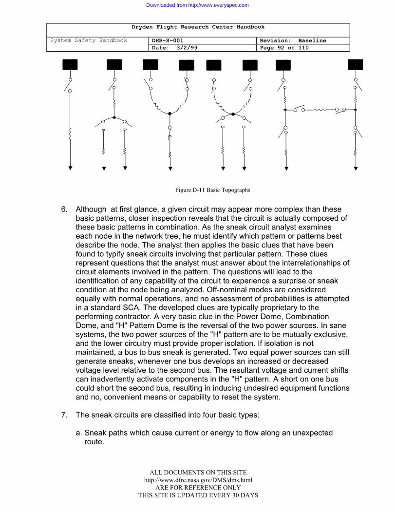
Dryden Flight Research Center Handbook
System Safety Handbook DHB-S-001 Revision: Baseline Date: 3/2/99 Page 92 of 110
PWR PWR PWR PWRPWR PWR PWR PWR
Figure D-11 Basic Topographs 6. Although at first glance, a given circuit may appear more complex than these
basic patterns, closer inspection reveals that the circuit is actually composed of these basic patterns in combination. As the sneak circuit analyst examines each node in the network tree, he must identify which pattern or patterns best describe the node. The analyst then applies the basic clues that have been found to typify sneak circuits involving that particular pattern. These clues represent questions that the analyst must answer about the interrelationships of circuit elements involved in the pattern. The questions will lead to the identification of any capability of the circuit to experience a surprise or sneak condition at the node being analyzed. Off-nominal modes are considered equally with normal operations, and no assessment of probabilities is attempted in a standard SCA. The developed clues are typically proprietary to the performing contractor. A very basic clue in the Power Dome, Combination Dome, and "H" Pattern Dome is the reversal of the two power sources. In sane systems, the two power sources of the "H" pattern are to be mutually exclusive, and the lower circuitry must provide proper isolation. If isolation is not maintained, a bus to bus sneak is generated. Two equal power sources can still generate sneaks, whenever one bus develops an increased or decreased voltage level relative to the second bus. The resultant voltage and current shifts can inadvertently activate components in the "H" pattern. A short on one bus could short the second bus, resulting in inducing undesired equipment functions and no, convenient means or capability to reset the system.
7. The sneak circuits are classified into four basic types:
a. Sneak paths which cause current or energy to flow along an unexpected
route.
ALL DOCUMENTS ON THIS SITE http://www.dfrc.nasa.gov/DMS/dms.html
ARE FOR REFERENCE ONLY THIS SITE IS UPDATED EVERY 30 DAYS
Downloaded from http://www.everyspec.com
Dryden Flight Research Center Handbook
System Safety Handbook DHB-S-001 Revision: Baseline Date: 3/2/99 Page 93 of 110
b. Sneak timing which may cause or prevent the flow of current or energy to
activate or inhibit a function at an unexpected time. c. Sneak indications which may cause an ambiguous or false display of system
operating conditions. d. Sneak labels which may cause incorrect stimuli to be initiated through
operator error.
8. When a potential sneak condition is identified, the analyst must verify that it is valid. The circuit is checked against the latest applicable drawings or revisions, and operational information may be reviewed concerning the system in question. If the sneak condition is verified, a Sneak Circuit Report is written which includes applicable drawings, an explanation of the condition(s), system- level impact, and a recommendation for elimination of the sneak. A typical Sneak Circuit Report is provided in Figure D-12.
9. During the course of analysis, unnecessary or undesirable circuit conditions are
sometimes. encountered. Such conditions as certain single failure points, un-supervised inductive loads, unnecessary components, and inadequate redundancy provisions are reported in the Design Concern Reports.
ALL DOCUMENTS ON THIS SITE http://www.dfrc.nasa.gov/DMS/dms.html
ARE FOR REFERENCE ONLY THIS SITE IS UPDATED EVERY 30 DAYS
Downloaded from http://www.everyspec.com
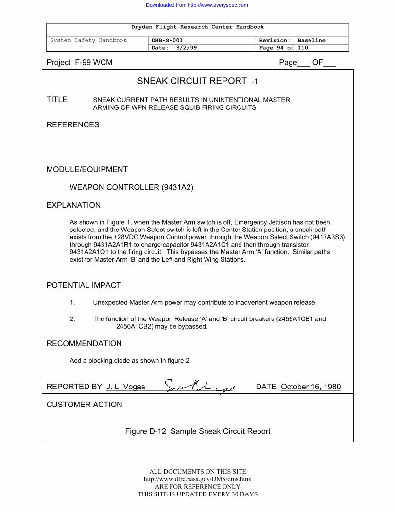
Dryden Flight Research Center Handbook
System Safety Handbook DHB-S-001 Revision: Baseline Date: 3/2/99 Page 94 of 110
Project F-99 WCM Page___ OF___
SNEAK CIRCUIT REPORT -1
TITLE SNEAK CURRENT PATH RESULTS IN UNINTENTIONAL MASTER ARMING OF WPN RELEASE SQUIB FIRING CIRCUITS REFERENCES MODULE/EQUIPMENT WEAPON CONTROLLER (9431A2) EXPLANATION As shown in Figure 1, when the Master Arm switch is off, Emergency Jettison has not been selected, and the Weapon Select switch is left in the Center Station position, a sneak path exists from the +28VDC Weapon Control power through the Weapon Select Switch (9417A3S3) through 9431A2A1R1 to charge capacitor 9431A2A1C1 and then through transistor 9431A2A1Q1 to the firing circuit. This bypasses the Master Arm ‘A’ function. Similar paths exist for Master Arm ‘B’ and the Left and Right Wing Stations. POTENTIAL IMPACT 1. Unexpected Master Arm power may contribute to inadvertent weapon release. 2. The function of the Weapon Release ‘A’ and ‘B’ circuit breakers (2456A1CB1 and 2456A1CB2) may be bypassed. RECOMMENDATION Add a blocking diode as shown in figure 2. REPORTED BY J. L. Vogas DATE October 16, 1980 CUSTOMER ACTION
Figure D-12 Sample Sneak Circuit Report
ALL DOCUMENTS ON THIS SITE http://www.dfrc.nasa.gov/DMS/dms.html
ARE FOR REFERENCE ONLY THIS SITE IS UPDATED EVERY 30 DAYS
Downloaded from http://www.everyspec.com
Dryden Flight Research Center Handbook
System Safety Handbook DHB-S-001 Revision: Baseline Date: 3/2/99 Page 95 of 110
ATTACHMENT 7: SOFTWARE HAZARD ANALYSIS (SWHA)
1.1 PURPOSE
The SWHA is an analysis technique which is a blend of the Failure Mode and Effects Analysis and the Fault Tree Analysis. The SWHA process does not become intensive until the Software Requirements Review, when sufficient detail is available. At this time, the SWHA is directed by the contractually identified hazardous events and the hardware PHA and FTA identified hazardous events. The SWHA will identify the. ability or inability of software to take the necessary corrective action when potentially hazardous hardware systems function or malfunction. It will determine the software response to the system functioning or malfunction and will determine as a result of the software response what, if any, additional software constraints are required to preclude the occurrence of these identified hazardous events.
2.1 DESCRIPTION
The SWHA identifies potential hazardous effects on the system, both external to the software (such as erroneous or improperly timed commands) and internally controlled (such as computer skips causing illegal entry into critical routines). The analysis takes into consideration the adequacy, inadequacy, or omission in software requirements for routines which take corrective action to eliminate or control the hazardous events identified for analysis. It also takes into consideration software and hardware interaction in all phases of the system's life cycle: Test, deployment, operation, maintenance, and disposal.
3.1 PROJECT PHASE
The SWHA is begun early in the concept phase so that its findings can be readily incorporated in the design. An early start helps avoid schedule delays and redesign costs.
4.1 ADVANTAGES/DISADVANTAGES
The SWHA allows the analyst to review all software, and to focus only on software segments which are safety critical. Care must be taken by the analyst to not -be overly concerned with every code error, sign error, or unused logic, as it would result in undue expenditure of resources relating to items which may have no safety impact.
ALL DOCUMENTS ON THIS SITE http://www.dfrc.nasa.gov/DMS/dms.html
ARE FOR REFERENCE ONLY THIS SITE IS UPDATED EVERY 30 DAYS
Downloaded from http://www.everyspec.com
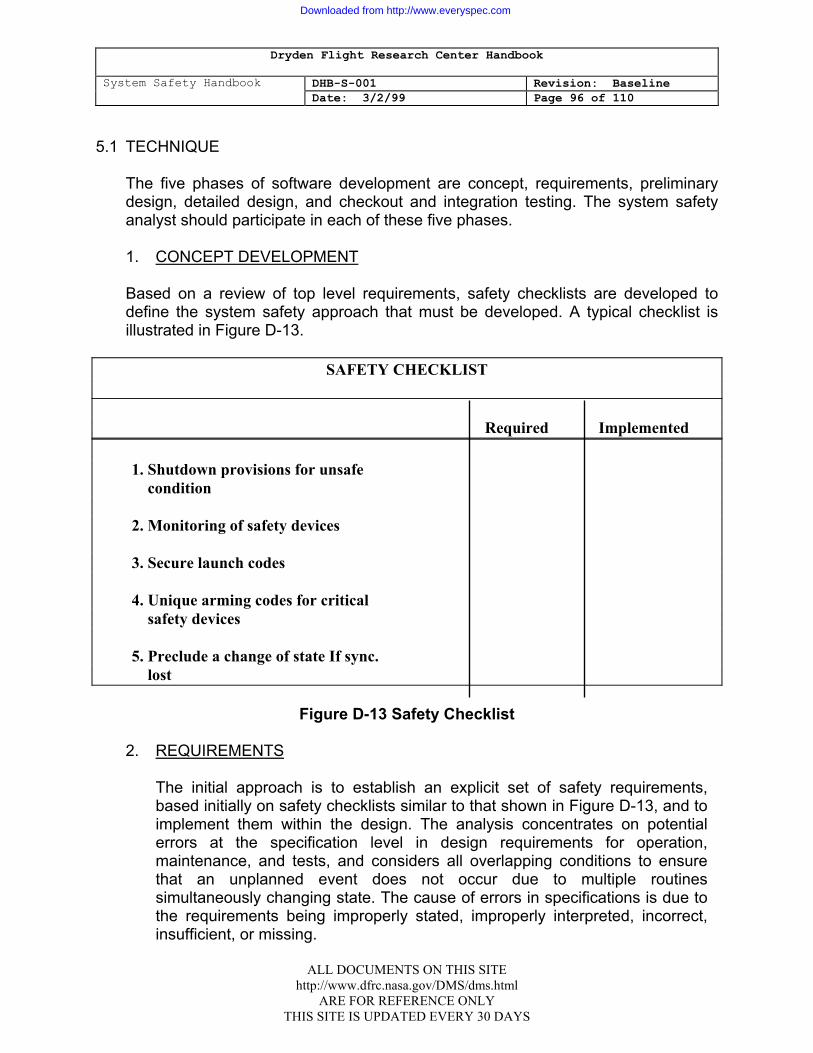
Dryden Flight Research Center Handbook
System Safety Handbook DHB-S-001 Revision: Baseline Date: 3/2/99 Page 96 of 110
5.1 TECHNIQUE
The five phases of software development are concept, requirements, preliminary design, detailed design, and checkout and integration testing. The system safety analyst should participate in each of these five phases. 1. CONCEPT DEVELOPMENT
Based on a review of top level requirements, safety checklists are developed to define the system safety approach that must be developed. A typical checklist is illustrated in Figure D-13.
SAFETY CHECKLIST Required Implemented 1. Shutdown provisions for unsafe condition 2. Monitoring of safety devices 3. Secure launch codes 4. Unique arming codes for critical safety devices 5. Preclude a change of state If sync. lost
Figure D-13 Safety Checklist 2. REQUIREMENTS
The initial approach is to establish an explicit set of safety requirements, based initially on safety checklists similar to that shown in Figure D-13, and to implement them within the design. The analysis concentrates on potential errors at the specification level in design requirements for operation, maintenance, and tests, and considers all overlapping conditions to ensure that an unplanned event does not occur due to multiple routines simultaneously changing state. The cause of errors in specifications is due to the requirements being improperly stated, improperly interpreted, incorrect, insufficient, or missing.
ALL DOCUMENTS ON THIS SITE http://www.dfrc.nasa.gov/DMS/dms.html
ARE FOR REFERENCE ONLY THIS SITE IS UPDATED EVERY 30 DAYS
Downloaded from http://www.everyspec.com

Dryden Flight Research Center Handbook
System Safety Handbook DHB-S-001 Revision: Baseline Date: 3/2/99 Page 97 of 110
3. PRELIMINARY DESIGN
a. Through review and analysis of the appropriate software documentation,
the analysis can reflect, in the SWHA, considerations of the effects of anomalies or deficiencies such as:
(1) Inadvertent character outputs. (2) Coexistence of command, control or test routines. (3) Improper sequencing. (4) Improper timing. (5) Failure to exit from routines. The top-down software development approach that is generally utilized during the software development process is reflected by column headings in Figure D-14.
(a) (b ) (c) (d) (e) (f) (g) (h) Software function Function description System Hazard Safety Impact Recommended Remarks/ Status (change) Summary Hazard Category Discussion/ Requirements to Means of Conclusion Control Hazard Implementation
Figure D-14 Software Hazard Analysis Format
b. The following paragraphs provide instructions in the use of this format by
reference to column heading.
(1) Software Function (Change). The particular software routine (or change if the original program is undergoing modification) is identified.
(2) Function Description Summary. Provide a brief summary of the purpose
of the function, including identification of any critical command/monitor which impacts safety.
(3) System Hazard. Provide a brief identification of a system hazard that
could occur from improper operation or-failure to operate.
ALL DOCUMENTS ON THIS SITE http://www.dfrc.nasa.gov/DMS/dms.html
ARE FOR REFERENCE ONLY THIS SITE IS UPDATED EVERY 30 DAYS
Downloaded from http://www.everyspec.com

Dryden Flight Research Center Handbook
System Safety Handbook DHB-S-001 Revision: Baseline Date: 3/2/99 Page 98 of 110
(4) Hazard Category. If the overall hazard category can be identified,
include here. If the effect of the hazard is across a system interface and therefore unidentifiable, a marginal flag (1>) should be entered.
(5) Safety Impact (Discussion/Conclusion). The potential hazard or non-
normal interface configuration caused by the improper operation should be discussed and any conclusions and supporting rationale for specific safety requirements should be provided.
(6) Recommended Requirements to Control Hazards. Provide
recommended safety requirements to eliminate or control the hazard within the software system. If the control cannot be implemented within the software, suggested external controls or requirement shall be listed.
(7) Remarks/Means of Implementation. Provide additional explanatory
comments as required. (8) Status. Include the status (open or closed), date of closure, and where
the implementation is documented.
4. DETAILED DESIGN a. An FTA (see Appendix D, Attachment 4) may be conducted at this point in
the development of the software system. The FTA begins by identifying a hardware level hazard and works into the software design identifying contributory events or faults affecting its occurrence. For quantification, it is possible to obtain a worst case estimate by assuming that an error exists. For critical segments it may be necessary to use conventional system safety analysis techniques to determine if the system meets the safety requirements. The worst case unconditional. probabilities may be sufficient to conclude the analysis; however, if concerns remain, it may be necessary to extend the analysis through the application of more realistic failure rates.
b. As the system design evolves, the FTA is continually updated and
eventually reflects the areas in which system hardware and software interaction (i.e., command, control and monitor) exists. To determine the significance of these software contributions to these potentially hazardous events, a detailed software hazard analysis will be accomplished. The software hazard analysis addresses the human interface and the hardware and software interfaces across all system elements at the system level and evaluates-both the effects of the software on all system elements and the effects of the system elements on the software. The safety analysis should reflect the ability or inability of the software to detect the status of safety critical devices, computer skip, entry into an improper routine, improper
ALL DOCUMENTS ON THIS SITE http://www.dfrc.nasa.gov/DMS/dms.html
ARE FOR REFERENCE ONLY THIS SITE IS UPDATED EVERY 30 DAYS
Downloaded from http://www.everyspec.com
Dryden Flight Research Center Handbook
System Safety Handbook DHB-S-001 Revision: Baseline Date: 3/2/99 Page 99 of 110
sequencing or timing, and the resultant corrective action that will. be taken to control or eliminate the hazardous condition (i.e., going to a standby mode or existing routine and safely terminating computer operations). The analysis assures that safety critical functions are adequately protected by inhibits, interlocks, or hardware. The. FTA will include the results of the software hazard analysis.
ALL DOCUMENTS ON THIS SITE http://www.dfrc.nasa.gov/DMS/dms.html
ARE FOR REFERENCE ONLY THIS SITE IS UPDATED EVERY 30 DAYS
Downloaded from http://www.everyspec.com
Dryden Flight Research Center Handbook
System Safety Handbook DHB-S-001 Revision: Baseline Date: 3/2/99 Page 100 of 110
ATTACHMENT 8: MANAGEMENT OVERSIGHT AND RISK TREE (MORT)
1.1 PURPOSE
MORT is an analytical procedure that provides a disciplined method for determining the causes and contributing factors of major accidents. It also is a tool to evaluate the quality of an existing safety system.
2.1 DESCRIPTION
1. The MORT is a special zed management system which focuses upon programmatic control of hazards. MORT utilizes a universal logic diagram or master "worksheet" to evaluate existing safety programs for accident/incident potential or to analyze a specific accident, and it makes extensive use of questions from the MORT User's Manual (ERDA-76/45-4, SSDC-4).
2. The MORT logic diagram is an idealized safety system model based upon the
fault tree method of system safety analysis. Basically, MORT is a fault tree which asks "what" oversights and missions could have contributed to accidents or incidents and "why" in terms of what failed in the management system. It also addresses those risks which have been completely analyzed and accepted by management as having adequate control.
3.1 PROJECT PHASE
The MORT technique can be implemented at any time to serve as the primary system safety program, as a method for investigating real or potential accidents, or for investigating changes in the system safety program, the project's management system, or in the hardware itself.
4.1 ADVANTAGES/DISADVANTAGES
The MORT provides relatively simple decision points in an accident analysis or safety system evaluation and enables an analyst or evaluator to detect omissions, oversights, or defects in the system or project. The technique is of particular value in accident/incident investigation as a means of discovering system or project weaknesses or errors which provide an environment conducive to mishaps. The task of organizing and structuring safety into functionally defined relationships and measurements creates a large amount of complex detail. Repeated practice and experience with the MORT diagram are necessary before good dexterity and skill in its application are acquired.
ALL DOCUMENTS ON THIS SITE http://www.dfrc.nasa.gov/DMS/dms.html
ARE FOR REFERENCE ONLY THIS SITE IS UPDATED EVERY 30 DAYS
Downloaded from http://www.everyspec.com
Dryden Flight Research Center Handbook
System Safety Handbook DHB-S-001 Revision: Baseline Date: 3/2/99 Page 101 of 110
5.1 TECHNIQUE
1. A MORT users manual has been prepared by the Department of Energy for use with the MORT analytical logic diagram. Both the manual and the diagram are essential to the understanding and full use of the MORT technique.
2. MORT is a special or specific application of an FTA. General features of the
MORT event tree are indicated in Figure D-15. 3. Construction layout depicts three main "branches" ordered with S/M (Specific
and Management), Oversights and Omissions on the left and R (Assumed Risks) on the right. The MORT technique requires events in the Assumed Risk Branch to be events transferred there from the Oversights and Omissions Branch. R factors are defined as only those risks that have been analyzed and accepted by the proper level of management; unanalyzed or unknown risks are not considered to be Assumed Risks.
4. Development of the two main branches comprising Oversights and Omissions
is ordered with S (Specific Control Factors) on the left and more general M (Management Systems Factors) on the right.
5. M factors are shown separate from the process that produced the
specific adverse event for two reasons:
a. Depiction of the existing management systems will suggest related background aspects of the specific system or accident that should be closely examined, and
b. The specific event may, in turn, suggest certain aspects of the management
systems which may truly be LTA less than adequate). 6. In general, the further development of the S Branch is keyed to time as well as
process. Left to right represents earlier to later, and bottom to top of the tree shows the sequence of causes from basic detailed causes to generic causes.
7. The key to understanding "programmatic" MORT is a close element-by
element examination of the MORT diagram. The diagram branches, in large part, are self-explanatory. Each element of the diagram branch presents a relatively simple question. One starts at the top of the diagram with the actual losses resulting from an accident or the potential loss if the diagram is being used to evaluate an existing safety program. Each of the three main factors (branches) is considered in turn. Detailed consideration of the S Branch is accomplished by reasoning backward in time through several 'sequences of
ALL DOCUMENTS ON THIS SITE http://www.dfrc.nasa.gov/DMS/dms.html
ARE FOR REFERENCE ONLY THIS SITE IS UPDATED EVERY 30 DAYS
Downloaded from http://www.everyspec.com

Dryden Flight Research Center Handbook
System Safety Handbook DHB-S-001 Revision: Baseline Date: 3/2/99 Page 102 of 110
contributing factors. The analysis ends when the question posed by the circled statement is answered with a "yes" or "no."
8. The MORT analytic diagram should be considered a working paper from which
pertinent facts about an accident or problem are derived and from which a safety report is developed.
ALL DOCUMENTS ON THIS SITE http://www.dfrc.nasa.gov/DMS/dms.html
ARE FOR REFERENCE ONLY THIS SITE IS UPDATED EVERY 30 DAYS
Downloaded from http://www.everyspec.com
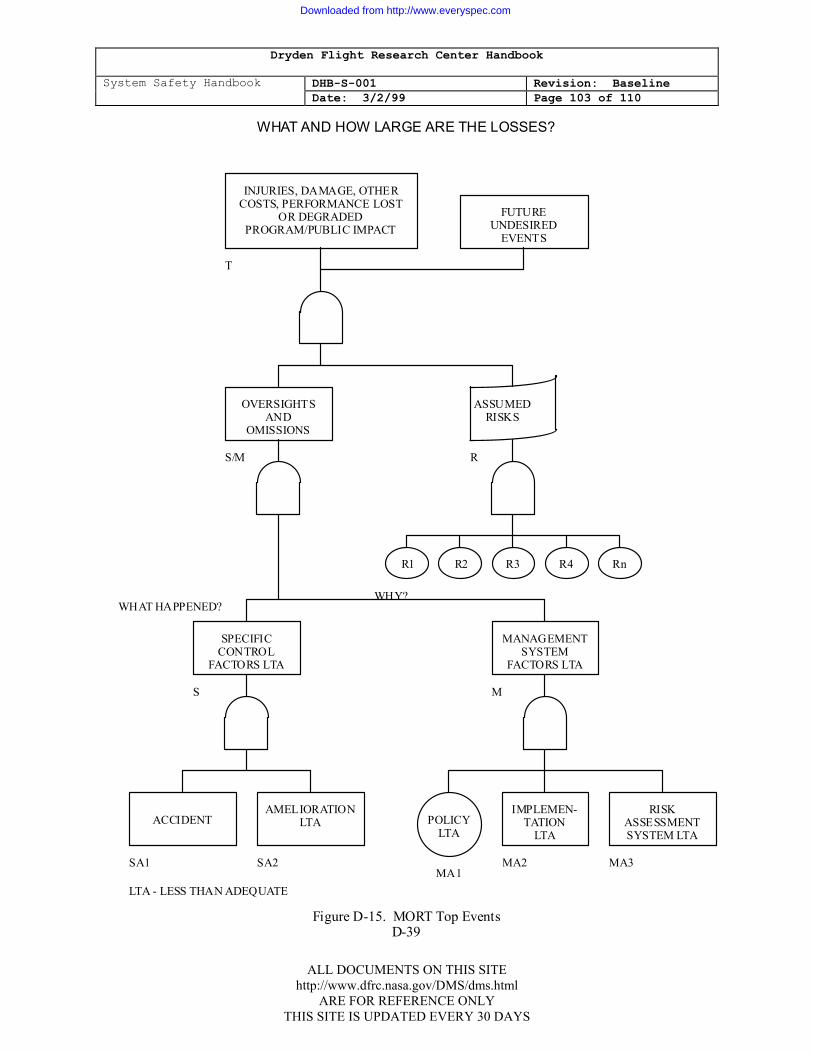
Dryden Flight Research Center Handbook
System Safety Handbook DHB-S-001 Revision: Baseline Date: 3/2/99 Page 103 of 110
WHAT AND HOW LARGE ARE THE LOSSES?
INJURIES, DAMAGE, OTHER COSTS, PERFORMANCE LOST
OR DEGRADED PROGRAM/PUBLIC IMPACT
FUTURE UNDESIRED
EVENTS
OVERSIGHTS AND
OMISSIONS
ASSUMED RISKS
R1 R2 R3 R4 Rn
SPECIFIC CONTROL
FACTORS LTA
MANAGEMENT SYSTEM
FACTORS LTA
RISK ASSESSMENT SYSTEM LTA
IMPLEMEN- TATION
LTAPOLICY
LTA
AMELIORATION LTAACCIDENT
LTA - LESS THAN ADEQUATE
Figure D-15. MORT Top Events D-39
T
S/M R
WHY?WHAT HAPPENED?
S M
SA1 SA2MA1
MA2 MA3
ALL DOCUMENTS ON THIS SITE http://www.dfrc.nasa.gov/DMS/dms.html
ARE FOR REFERENCE ONLY THIS SITE IS UPDATED EVERY 30 DAYS
Downloaded from http://www.everyspec.com

Dryden Flight Research Center Handbook
System Safety Handbook DHB-S-001 Revision: Baseline Date: 3/2/99 Page 104 of 110
ATTACHMENT 9: SUPPORT ANALYSES
1.1 INTRODUCTION
Support analyses may be required to validate selected safety features of a system, to determine hazard 'severity, or to establish the margin of safety of the design when such data are not otherwise available. The requirements for imposing these analyses for certain components in space flight systems, aeronautical systems, Government furnished equipment, and facilities should be included in the design specifications. Support analyses include:
1. Stress analysis.
2. Stress corrosion analysis. 3. Fracture control analysis. 4. Materials analysis - flammability, toxicity, and off-gassing. 5. Chemical hazard analysis. 6. Radiation (ionizing and non-ionizing) hazard analysis. 7. Mockups and simulations. 8. RF/EMI (radio frequency/electromagnetic interference) analysis. 9. Fluid compatibility analysis.
2.1 GUIDELINES
The following sections provide guidelines for imposing these analyses in applications not subject to the requirements of paragraph 2.2.
1. STRESS ANALYSIS
Stress analysis should be performed when the system safety engineer believes a single point of failure in a structural member may. cause injury or major facility damage. These are usually restricted to mandated structures but may be required elsewhere to, determine the need for additional safety requirements such as barriers, remote controls, or environmental protection.
ALL DOCUMENTS ON THIS SITE http://www.dfrc.nasa.gov/DMS/dms.html
ARE FOR REFERENCE ONLY THIS SITE IS UPDATED EVERY 30 DAYS
Downloaded from http://www.everyspec.com
Dryden Flight Research Center Handbook
System Safety Handbook DHB-S-001 Revision: Baseline Date: 3/2/99 Page 105 of 110
2. STRESS CORROSION ANALYSIS
Stress corrosion should be considered most probable at the point at which a metallic structural member is most highly strained. The effects of corrosion are much more severe under stress then under ordinary conditions, and such members- will fail with fewer stress applications. Another factor to be considered is the corrosive environment in question. MSFC-SPEC-522, "Design Criteria for Controlling Stress Corrosion Cracking," provides guidance in selecting materials to be used in the design of equipment structures, support brackets and mounting hardware where stress corrosion is a factor.
3. FRACTURE CONTROL ANALYSIS When adequate warning or redundancy measures are not feasible and the
failure of a structure can result in a catastrophic event, a fracture control analysis should be considered. It can identify structural members subject to failure because of the propagation of flaws or crack-like defects introduced during fabrication, testing, and service life. A history of stress cycling should be maintained and allowances made for replacement, if necessary, at a later date.
4. MATERIALS ANALYSIS - FLAMMABILITY, TOXICITY, AND OFF-
GASSING Materials which are flammable, toxic, or produce toxic off-gassing should be
avoided in habitable areas. NHB 8060.1, Flammability, Odor, and Off-gassing Requirements and Test Procedures for Materials in Environments that Support Combustion," provides guidance in selecting, testing, and certifying materials which may be used in contact with fuels, oxidizers, or combustible gases. SE-R-0006, "General Specifications, NASA JSC Requirements for Materials and Processes," provides guidance for selection of materials to be used in an atmosphere that supports combustion.
5. CHEMICAL HAZARD ANALYSIS The need for chemical hazard analyses can be determined early by evaluating
data such as drawings, procedures, and specifications to identify uses of chemicals. At an operating location, the purchase requests, project plans, and new proposals can identify potential chemicals and their use.
6. RADIATION (IONIZING AND NON-IONIZING) HAZARD ANALYSIS All sources of radiation should be identified and analyzed for types of radiation,
intended uses, locations, population and equipment exposures, and inspection requirements. Guidelines for these analyses and requirements include NHB 1700.7, KHB 1700.7, JSC 07700, JSC 13830, and DH 1-6. Radiation sources
ALL DOCUMENTS ON THIS SITE http://www.dfrc.nasa.gov/DMS/dms.html
ARE FOR REFERENCE ONLY THIS SITE IS UPDATED EVERY 30 DAYS
Downloaded from http://www.everyspec.com
Dryden Flight Research Center Handbook
System Safety Handbook DHB-S-001 Revision: Baseline Date: 3/2/99 Page 106 of 110
can be identified by analyzing the drawings, procedures, specifications, work orders, purchase orders, project plans and proposals, and by monitoring with radiation detecting devices.
7. MOCKUPS AND SIMULATIONS When adequate data are not otherwise available, the use of mockups and
simulations can serve as primary sources of data and-are an excellent basis for safety judgments and design decisions for new systems. A reasonable approximation of the use environment can be obtained by]testing portions of the system which are considered essentially independent or whose interaction with the rest of the system can be simulated. In a simulation or isolation of a subsystem, the critical system interaction must be considered. Some cause-effect characteristics may be developed mathematically. This can be done with reasonable accuracy for electrical networks and structural components because of the accurate specifications of manufacturing tolerances and the ability to express theoretical relationships. In other cases, approximate models may be used and the engineer must be aware of the possibility of neglecting critical factors. When the approximation is based upon semi-quantitative data, liberal limits of error must be included.
8. RADIO FREQUENCY (RF)/ELECTROMAGNETIC INTERFERENCE(EMI)
ANALYSIS RF/EMI analyses should be considered for pulse or clock interface circuits with
a pulse repetition rate of greater than 50K pps, signals with fundamental frequencies greater than 50 KHz, or circuits. processing pulse rise/fall times equal to or less than 10 microseconds. Guidelines for these analyses and tests include JSC specification SL-E-0001 and MIL-E-60511.
9. FLUID COMPATIBILITY ANALYSIS Particular attention should be given to the analysis of materials used in
systems containing hazardous fluids. These include gaseous oxygen, liquid oxygen, propellants, oxidizers, fine grained solids suspended in gas, and others that could theoretically cause exothermic or adiabatic reactions. Materials in a system which could be exposed to hazardous fluids directly or by a single failure should be included in these analyses. NHB 8060.1 provides requirements for materials exposed to hazardous fluids.
ALL DOCUMENTS ON THIS SITE http://www.dfrc.nasa.gov/DMS/dms.html
ARE FOR REFERENCE ONLY THIS SITE IS UPDATED EVERY 30 DAYS
Downloaded from http://www.everyspec.com
Dryden Flight Research Center Handbook
System Safety Handbook DHB-S-001 Revision: Baseline Date: 3/2/99 Page 107 of 110
APPENDIX E: RISK ASSESSMENT APPROACH
1.1 INTRODUCTION
The decision to assume a risk is a management responsibility. The major factors to be considered should be the severity of the risk and the potential of the risk occurring. Paragraph 2.5 sets forth the criteria that risk assessments must be performed as a part of the risk management process. The intent of this appendix is to provide a technique for performing the risk assessment.
2.1 RISK ASSESSMENT TECHNIQUE
Decisions regarding resolution of identified hazards should be based on an assessment of the risk involved. To aid in the achievement of the objectives of system safety, hazards may be characterized by severity categories and probability levels. Since the priority for system safety is eliminating hazards by design, a risk assessment procedure considering only hazard severity will generally suffice during the early design phase. When hazards are not eliminated during the early design phase, a risk assessment procedure based upon the hazard probability, as well as hazard severity, should be used to establish priorities for corrective action and resolution of identified hazards.
1. HAZARD SEVERITY
Hazard severity categories (Figure E-1) are defined to provide a qualitative measure of the worst credible mishap resulting from personnel error; environmental conditions; design inadequacies; procedural deficiencies; or system, subsystem, or component failure or malfunction. These hazard severity categories may provide guidance for a wide variety of projects. Adaptation to a particular project is generally required to provide a mutual understanding between the NASA Center and the contractors as to the meaning of the terms used in the category definitions. The adaptation must define what constitutes system loss, major and minor system damage, and severe and minor injury, and severe and minor occupational illness.
ALL DOCUMENTS ON THIS SITE http://www.dfrc.nasa.gov/DMS/dms.html
ARE FOR REFERENCE ONLY THIS SITE IS UPDATED EVERY 30 DAYS
Downloaded from http://www.everyspec.com
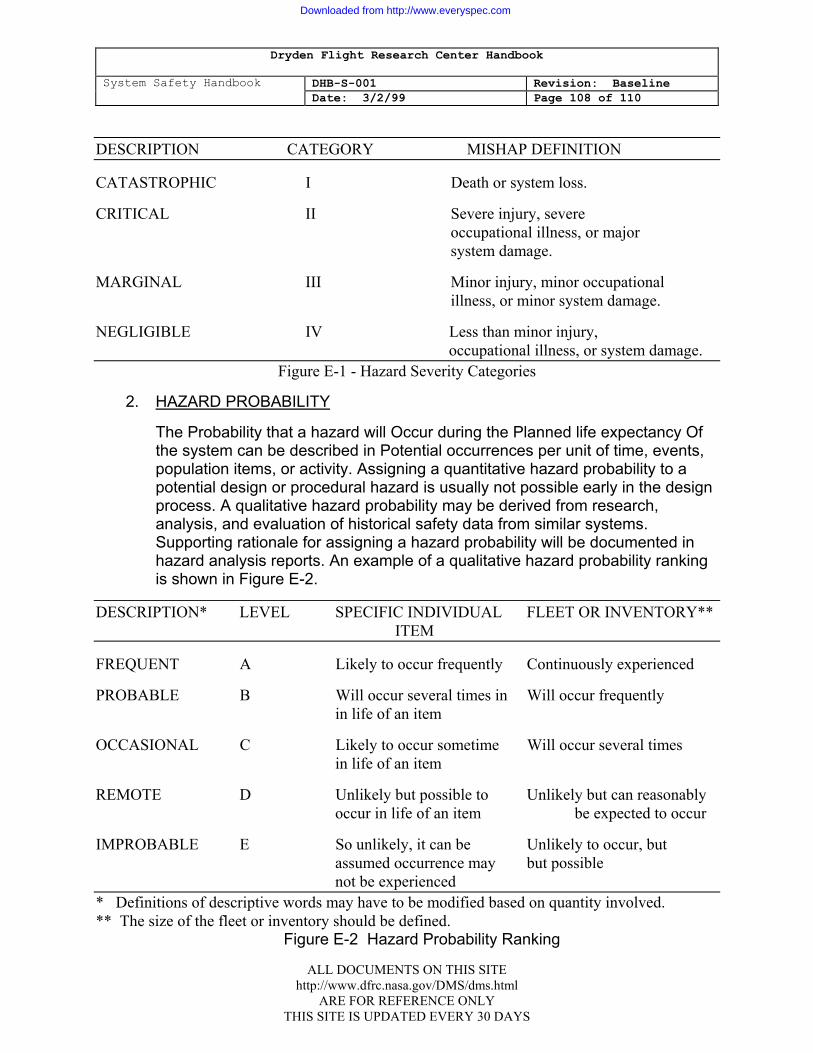
Dryden Flight Research Center Handbook
System Safety Handbook DHB-S-001 Revision: Baseline Date: 3/2/99 Page 108 of 110
DESCRIPTION CATEGORY MISHAP DEFINITION
CATASTROPHIC I Death or system loss.
CRITICAL II Severe injury, severe occupational illness, or major system damage.
MARGINAL III Minor injury, minor occupational illness, or minor system damage.
NEGLIGIBLE IV Less than minor injury, occupational illness, or system damage.
Figure E-1 - Hazard Severity Categories
2. HAZARD PROBABILITY
The Probability that a hazard will Occur during the Planned life expectancy Of the system can be described in Potential occurrences per unit of time, events, population items, or activity. Assigning a quantitative hazard probability to a potential design or procedural hazard is usually not possible early in the design process. A qualitative hazard probability may be derived from research, analysis, and evaluation of historical safety data from similar systems. Supporting rationale for assigning a hazard probability will be documented in hazard analysis reports. An example of a qualitative hazard probability ranking is shown in Figure E-2.
DESCRIPTION* LEVEL SPECIFIC INDIVIDUAL FLEET OR INVENTORY** ITEM
FREQUENT A Likely to occur frequently Continuously experienced
PROBABLE B Will occur several times in Will occur frequently in life of an item
OCCASIONAL C Likely to occur sometime Will occur several times in life of an item
REMOTE D Unlikely but possible to Unlikely but can reasonably occur in life of an item be expected to occur
IMPROBABLE E So unlikely, it can be Unlikely to occur, but assumed occurrence may but possible not be experienced * Definitions of descriptive words may have to be modified based on quantity involved. ** The size of the fleet or inventory should be defined.
Figure E-2 Hazard Probability Ranking
ALL DOCUMENTS ON THIS SITE http://www.dfrc.nasa.gov/DMS/dms.html
ARE FOR REFERENCE ONLY THIS SITE IS UPDATED EVERY 30 DAYS
Downloaded from http://www.everyspec.com
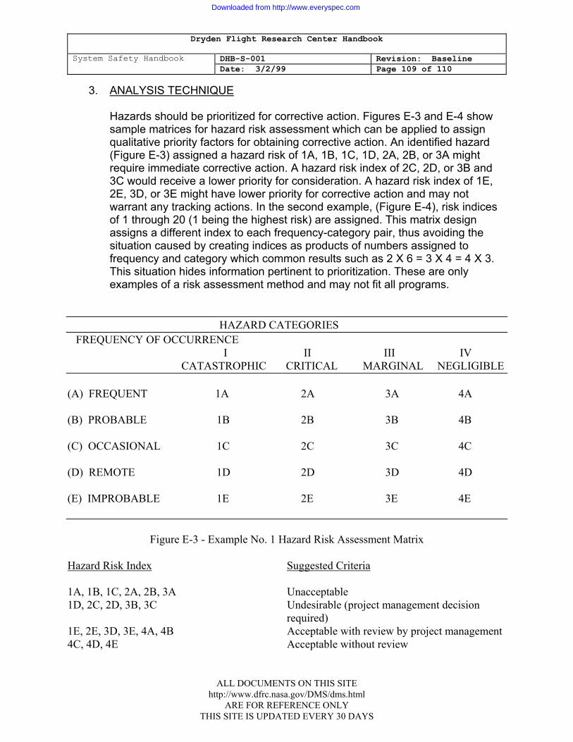
Dryden Flight Research Center Handbook
System Safety Handbook DHB-S-001 Revision: Baseline Date: 3/2/99 Page 109 of 110
3. ANALYSIS TECHNIQUE
Hazards should be prioritized for corrective action. Figures E-3 and E-4 show sample matrices for hazard risk assessment which can be applied to assign qualitative priority factors for obtaining corrective action. An identified hazard (Figure E-3) assigned a hazard risk of 1A, 1B, 1C, 1D, 2A, 2B, or 3A might require immediate corrective action. A hazard risk index of 2C, 2D, or 3B and 3C would receive a lower priority for consideration. A hazard risk index of 1E, 2E, 3D, or 3E might have lower priority for corrective action and may not warrant any tracking actions. In the second example, (Figure E-4), risk indices of 1 through 20 (1 being the highest risk) are assigned. This matrix design assigns a different index to each frequency-category pair, thus avoiding the situation caused by creating indices as products of numbers assigned to frequency and category which common results such as 2 X 6 = 3 X 4 = 4 X 3. This situation hides information pertinent to prioritization. These are only examples of a risk assessment method and may not fit all programs.
HAZARD CATEGORIES
FREQUENCY OF OCCURRENCE I II III IV
CATASTROPHIC CRITICAL MARGINAL NEGLIGIBLE (A) FREQUENT 1A 2A 3A 4A (B) PROBABLE 1B 2B 3B 4B (C) OCCASIONAL 1C 2C 3C 4C (D) REMOTE 1D 2D 3D 4D (E) IMPROBABLE 1E 2E 3E 4E
Figure E-3 - Example No. 1 Hazard Risk Assessment Matrix
Hazard Risk Index Suggested Criteria 1A, 1B, 1C, 2A, 2B, 3A Unacceptable 1D, 2C, 2D, 3B, 3C Undesirable (project management decision required) 1E, 2E, 3D, 3E, 4A, 4B Acceptable with review by project management 4C, 4D, 4E Acceptable without review
ALL DOCUMENTS ON THIS SITE http://www.dfrc.nasa.gov/DMS/dms.html
ARE FOR REFERENCE ONLY THIS SITE IS UPDATED EVERY 30 DAYS
Downloaded from http://www.everyspec.com
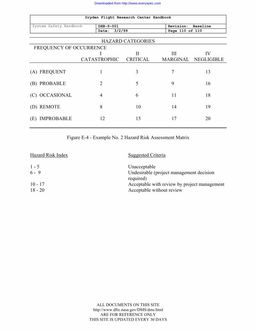
Dryden Flight Research Center Handbook
System Safety Handbook DHB-S-001 Revision: Baseline Date: 3/2/99 Page 110 of 110
HAZARD CATEGORIES
FREQUENCY OF OCCURRENCE I II III IV CATASTROPHIC CRITICAL MARGINAL NEGLIGIBLE
(A) FREQUENT 1 3 7 13 (B) PROBABLE 2 5 9 16 (C) OCCASIONAL 4 6 11 18 (D) REMOTE 8 10 14 19 (E) IMPROBABLE 12 15 17 20
Figure E-4 - Example No. 2 Hazard Risk Assessment Matrix
Hazard Risk Index Suggested Criteria 1 - 5 Unacceptable 6 - 9 Undesirable (project management decision required) 10 - 17 Acceptable with review by project management 18 - 20 Acceptable without review
ALL DOCUMENTS ON THIS SITE http://www.dfrc.nasa.gov/DMS/dms.html
ARE FOR REFERENCE ONLY THIS SITE IS UPDATED EVERY 30 DAYS
Downloaded from http://www.everyspec.com