Embed Size (px)
Citation preview
Power Plant and Transmission System Power Plant and Transmission System Protection CoordinationProtection Coordination
Phase Distance (21) and VoltagePhase Distance (21) and Voltage--Controlled or Controlled or VoltageVoltage--Restrained Overcurrent Protection (51V)Restrained Overcurrent Protection (51V)
System Protection and Control Subcommittee Protection Coordination Workshop
Phoenix, AZMarch 17-18, 2010
2AgendaAgenda
Objectives
Description of Protection Functions
Discuss and Describe System Events that Could Create Conditions that Would Cause Operation of These Functions
Seven Step Process for both Functions 21 and 51V•
Function 21 –
Phase Distance Protection
•
Function 51V –
Voltage-Controlled or Voltage-Restrained Overcurrent Protection
3AgendaAgenda
What is important to Coordination•
Settings that Protect the Generator
•
Back Up Protection for Transmission System Protection
•
Calculation of Apparent Impedance with Infeed Current
•
Generator Field Forcing Effects During System Stressed Voltage Conditions
•
Loadability Issues During Stressed System Conditions
Questions
and Answers
4ObjectiveObjective
Increase knowledge of recommended generator protection for system back-up using phase distance and voltage-controlled or voltage-restrained overcurrent functions.
Facilitate improved coordination between power plant and transmission system protection for these specific protection functions.
5
The Need for Phase Distance System The Need for Phase Distance System BackBack--Up Protection Up Protection –– Function 21Function 21
“The distance relay applied for this function is intended to isolate the generator from the power system for a fault which is not cleared by the transmission line breakers.”
“Within its operating zone, the tripping time for this relay must coordinate with the longest time delay for the phase distance relays on the transmission lines connected to the generating substation bus.”
IEEE C37.102-2006 –
Guide for AC Generator Protection, Section 4.6.1.1 (emphasis added)
6
The Need for VoltageThe Need for Voltage--Controlled or Controlled or --Restrained Overcurrent Protection Restrained Overcurrent Protection –– Function 51VFunction 51V
“Its function is to provide backup protection for system faults when the power system to which the generator is connected is protected by time-current coordinated protections.”
“The type of overcurrent device generally used for system phase fault backup protection is either a voltage- restrained or voltage-controlled time-overcurrent relay. Both types of relays are designed to restrain operation under emergency overload conditions and still provide adequate sensitivity for the detection of faults.”
IEEE C37.102-2006 –
Guide for AC Generator Protection, Section 4.6.1.2
7
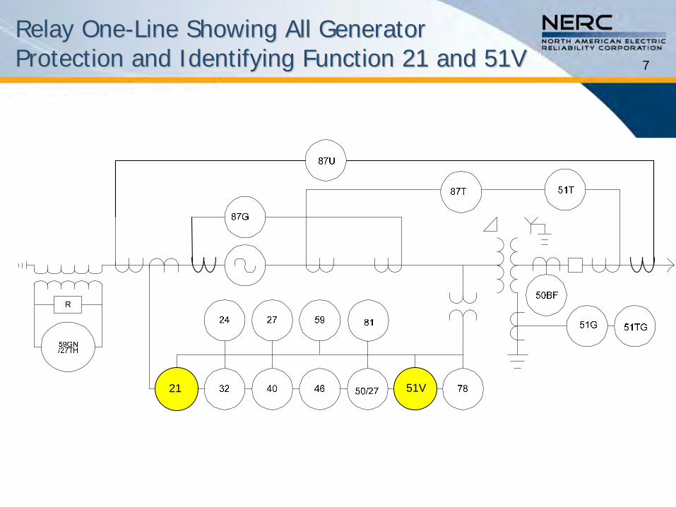
21 51V
Relay OneRelay One--Line Showing All Generator Line Showing All Generator Protection and Identifying Function 21 and 51VProtection and Identifying Function 21 and 51V
8
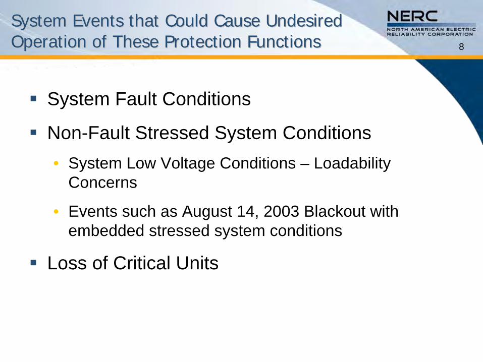
System Events that Could Cause Undesired System Events that Could Cause Undesired Operation of These Protection FunctionsOperation of These Protection Functions
System Fault Conditions
Non-Fault Stressed System Conditions•
System Low Voltage Conditions –
Loadability
Concerns
•
Events such as August 14, 2003 Blackout with embedded stressed system conditions
Loss of Critical Units
9
Seven Step Process for Seven Step Process for both Functions 21 and 51Vboth Functions 21 and 51V
This is the process used throughout the coordination Technical Reference Document to address each protective function as appropriate.
The following slides will take a step-by-step approach through both Function 21 and 51V.
The next two slides provide the general data and information requirements from the Generator, Transmission, and Distribution Owners.
10
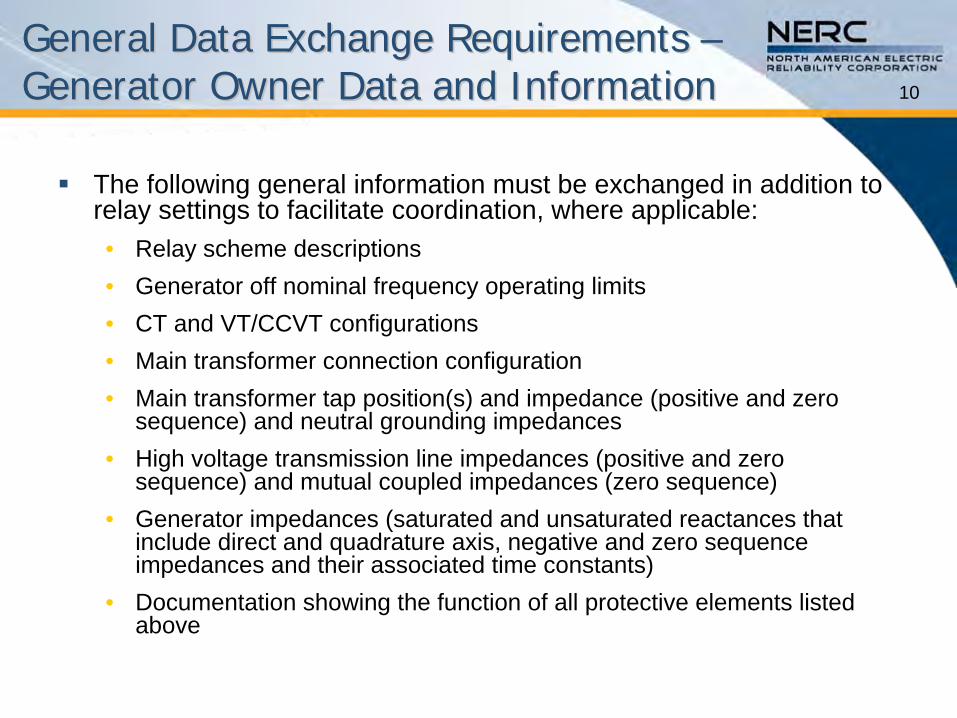
General Data Exchange Requirements General Data Exchange Requirements –– Generator Owner Data and InformationGenerator Owner Data and Information
The following general information must be exchanged in addition to relay settings to facilitate coordination, where applicable:•
Relay scheme descriptions•
Generator off nominal frequency operating limits•
CT and VT/CCVT configurations •
Main transformer connection configuration•
Main transformer tap position(s) and impedance (positive and zero sequence) and neutral grounding impedances
•
High voltage transmission line impedances (positive and zero sequence) and mutual coupled impedances (zero sequence)
•
Generator impedances (saturated and unsaturated reactances that include direct and quadrature axis, negative and zero sequence impedances and their associated time constants)
•
Documentation showing the function of all protective elements listed above
11
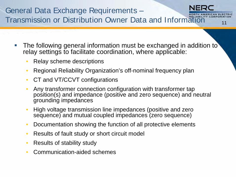
General Data Exchange Requirements – Transmission or Distribution Owner Data and Information
The following general information must be exchanged in addition to relay settings to facilitate coordination, where applicable:•
Relay scheme descriptions•
Regional Reliability Organization’s off-nominal frequency plan •
CT and VT/CCVT configurations•
Any transformer connection configuration with transformer tap position(s) and impedance (positive and zero sequence) and neutral grounding impedances
•
High voltage transmission line impedances (positive and zero sequence) and mutual coupled impedances (zero sequence)
•
Documentation showing the function of all protective elements•
Results of fault study or short circuit model•
Results of stability study•
Communication-aided schemes
12
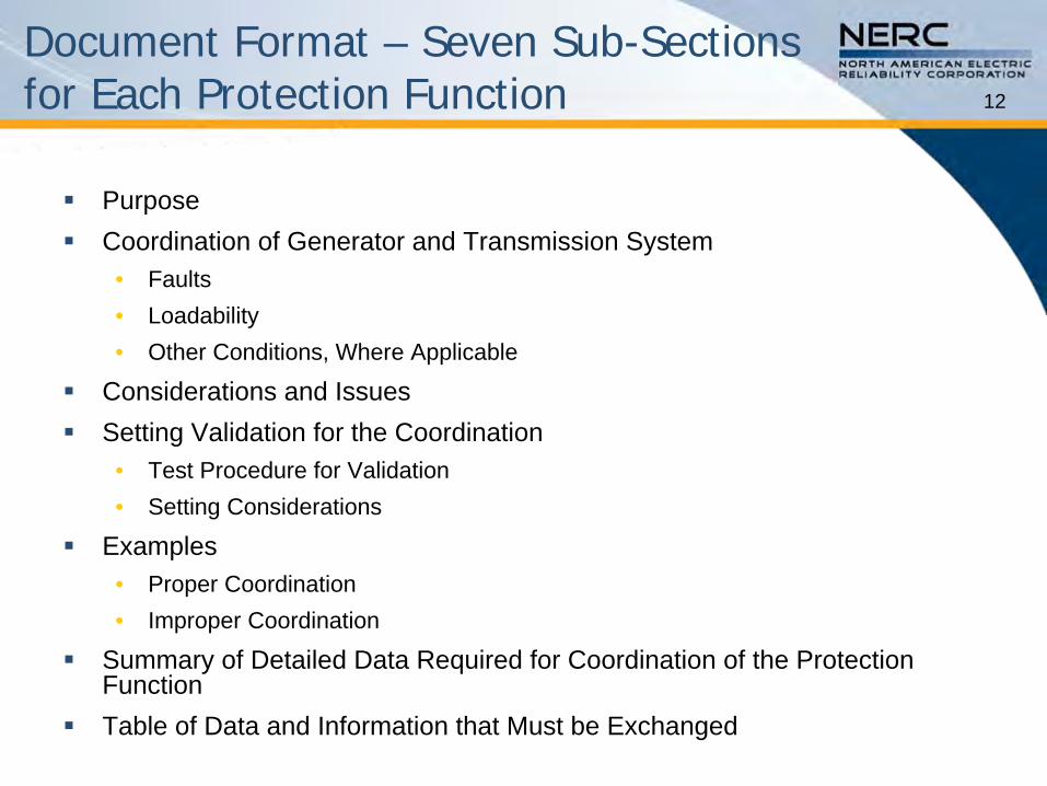
Document Format – Seven Sub-Sections for Each Protection Function
Purpose
Coordination of Generator and Transmission System•
Faults•
Loadability•
Other Conditions, Where Applicable
Considerations and Issues
Setting Validation for the Coordination•
Test Procedure for Validation •
Setting Considerations
Examples•
Proper Coordination•
Improper Coordination
Summary of Detailed Data Required for Coordination of the Protection Function
Table of Data and Information that Must be Exchanged
Purpose•
For Machine only coverage –
Set relay focusing on
thermal protection of the generator for a transmission fault that is not cleared.
•
For System Trip Dependability (relay failure coverage) –
Provide relay failure protection for all
transmission lines and transformers connected to the generator’s high voltage bus.
13Phase Distance Protection Phase Distance Protection –– Function 21Function 21
14
Function 21 Function 21 –– For For MachineMachine--Only CoverageOnly Coverage
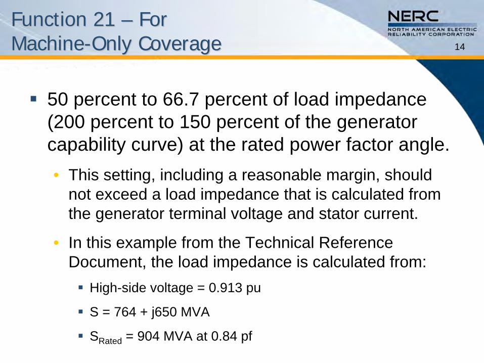
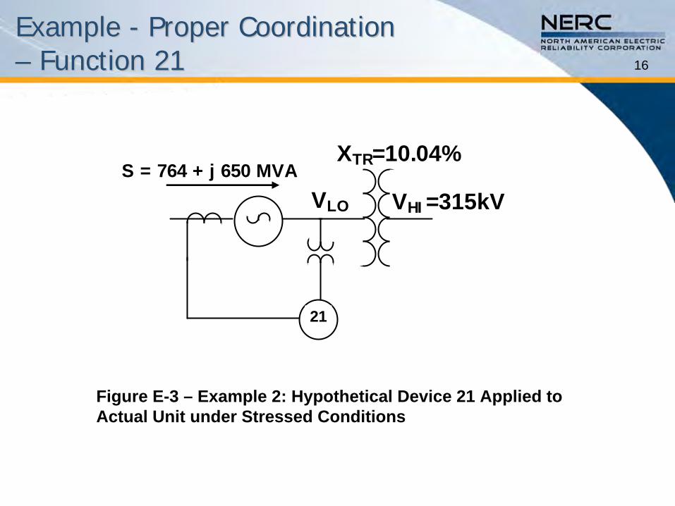
50 percent to 66.7 percent of load impedance (200 percent to 150 percent of the generator capability curve) at the rated power factor angle.•
This setting, including a reasonable margin, should not exceed a load impedance that is calculated from the generator terminal voltage and stator current.
•
In this example from the Technical Reference Document, the load impedance is calculated from:
High-side voltage = 0.913 pu
S = 764 + j650 MVA
SRated
= 904 MVA at 0.84 pf
15
Coordination of Generator and Coordination of Generator and Transmission System Transmission System –– Function 21Function 21
Loadability•
C37.102 presented a range of likely acceptable settings for the impedance relay of 150 percent to 200 percent of the generator MVA rating at rated power factor as settings that will not operate for normal generator outputs.
•
This setting can be re-stated in terms of impedance as 0.66 –
0.50 per unit ohms on the machine base.
•
This document addresses distance relay applications for which the voltage regulator action could cause an incorrect trip based on a fixed-
field model basis.
To fully address dynamic effects during stressed system conditions, a dynamic simulation of the unit and excitation system is required
to properly assess the security of the protection function.
The SPCS is investigating approaches to model these dynamic effects.
•
Most exciters have a field forcing function [2], IEEE Standard 421.1-
2007 (appendix A reference 2), that enables the exciter to go beyond its full load output.
•
These outputs can last up to several seconds before controls reduce the exciter field currents to rated output.
16
Example Example -- Proper Coordination Proper Coordination –– Function 21Function 21
Figure E-3 –
Example 2: Hypothetical Device 21 Applied to Actual Unit under Stressed Conditions
21
VLO VHI =315kVS = 764 + j 650 MVA
XTR=10.04%
17
Example Example -- Proper Coordination Proper Coordination –– Function 21Function 21
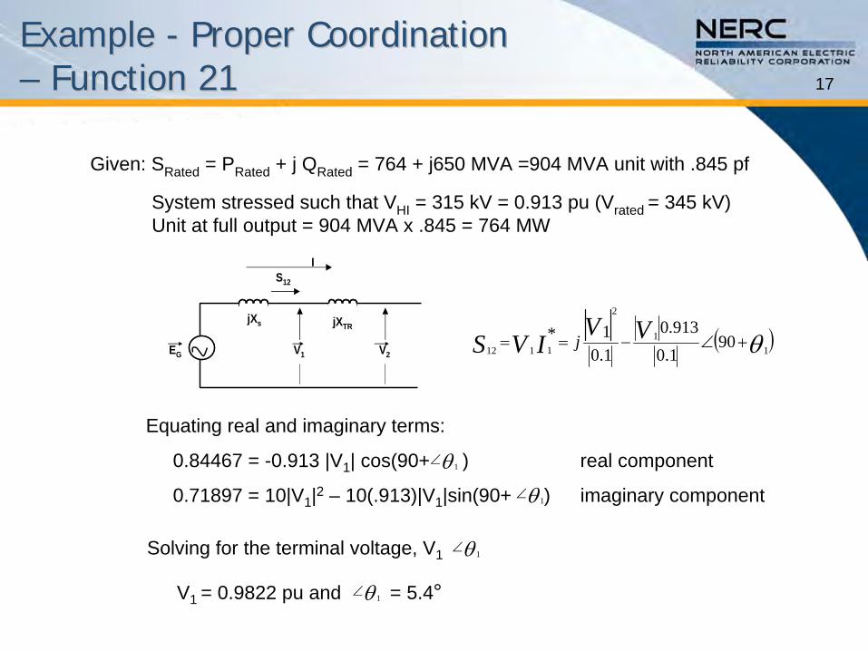
Given: SRated
= PRated
+ j QRated
= 764 + j650 MVA =904 MVA unit with .845 pf
System stressed such that VHI
= 315 kV = 0.913 pu (Vrated = 345 kV)Unit at full output = 904 MVA x .845 = 764 MW
11
2
111290
1.0913.0
1.01* VV
IVS j
Solving for the terminal voltage, V1 1
V1 V2
jXs jXTR
EG
S12
I
Equating real and imaginary terms:
0.84467 = -0.913 |V1
| cos(90+ ) real component
0.71897 = 10|V1
|2
–
10(.913)|V1
|sin(90+ )
imaginary component
V1 = 0.9822 pu and = 5.4° 1
1
1
18
Example Example -- Proper Coordination Proper Coordination –– Function 21Function 21
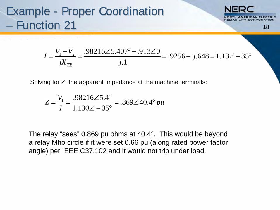
The relay “sees”
0.869 pu ohms at 40.4°. This would be beyond a relay Mho circle if it were set 0.66 pu (along rated power factor angle) per IEEE C37.102 and it would not trip under load.
3513.1648.9256.1.
0913.407.598216.21 jjjX
VVITR
puIVZ
4.40869.35130.14.598216.1
Solving for Z, the apparent impedance at the machine terminals:
19
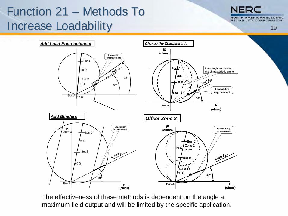
Function 21 Function 21 –– Methods To Methods To Increase LoadabilityIncrease Loadability
30°
35°
Loadability improvement
Load Z 30°
Add Load Encroachment
Bus A
Bus B
Bus C
60 Ω
60 Ω
10 Ω
Load Z 30°
60Ω
40Ω
Bus C
Bus B
Bus A
jX(ohms)
R (ohms)
Change the Characteristic
30°
Loadability improvement
Lens angle also called the characteristic angle
Load Z 30°
60Ω
40Ω
Bus C
Bus B
Bus A
jX(ohms)
R (ohms)
Change the Characteristic
30°
Loadability improvement
Lens angle also called the characteristic angle
Add Blinders
Load Z30°
jX(ohms)
R (ohms)
30°
Loadability improvement
Bus A
Bus B
Bus C
60 Ω
40 Ω
R (ohms)
jX(ohms)
30°
Load Z 30°
Loadability improvement
Zone 1
Zone 2 offset
Offset Zone 2
Bus A
Bus B
Bus C
60 Ω
40 Ω
R (ohms)
jX(ohms)
30°30°
Load Z 30°
Loadability improvement
Zone 1
Zone 2 offset
Offset Zone 2
Bus A
Bus B
Bus C
60 Ω
40 Ω
The effectiveness of these methods is dependent on the angle at maximum field output and will be limited by the specific application.
20
Set Device 21 For System Trip Set Device 21 For System Trip Dependability (Relay Failure Coverage)Dependability (Relay Failure Coverage)
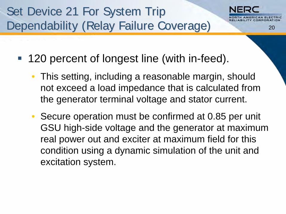
120 percent of longest line (with in-feed). •
This setting, including a reasonable margin, should not exceed a load impedance that is calculated from the generator terminal voltage and stator current.
•
Secure operation must be confirmed at 0.85 per unit GSU high-side voltage and the generator at maximum real power out and exciter at maximum field for this condition using a dynamic simulation of the unit and excitation system.
21
Coordination of Generator and Coordination of Generator and Transmission System Transmission System –– Function 21Function 21
Faults•
The detection of a fault is most easily demonstrated by the examples in section 3.1.5.
•
In the examples, it will be assumed that a transmission line relay failure has occurred and the fault is at the far end of the protected line.
•
The examples will present solutions that can be used to permit tripping for the fault while not tripping for non-fault conditions when the generator is not at risk.
22
Example Example -- Proper Coordination Proper Coordination –– Function 21Function 21
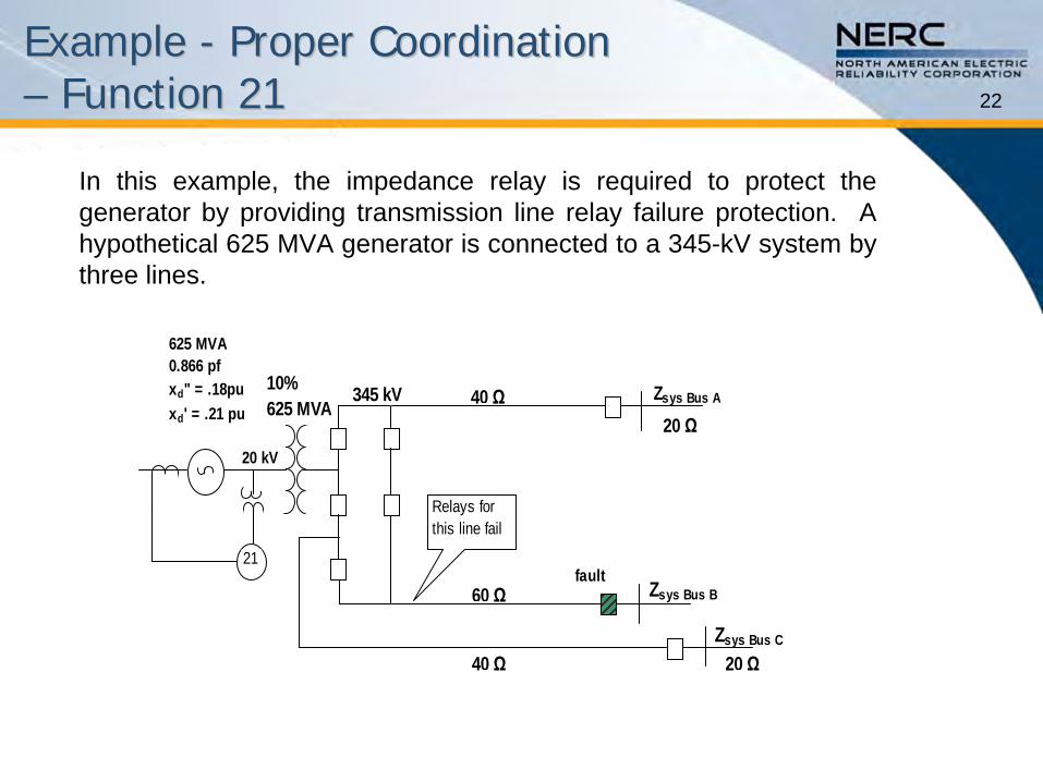
In this example, the impedance relay is required to protect the generator by providing transmission line relay failure protection. A hypothetical 625 MVA generator is connected to a 345-kV system by three lines.
faultZsys Bus B
Zsys Bus C
Zsys Bus A
60 Ω
40 Ω
40 Ω 20 Ω
20 Ω
625 MVA 0.866 pfxd" = .18puxd' = .21 pu
10%625 MVA
345 kV
Relays for this line fail
20 kV
21
23
Calculation for Apparent Impedance Calculation for Apparent Impedance with Infeed Currentwith Infeed Current
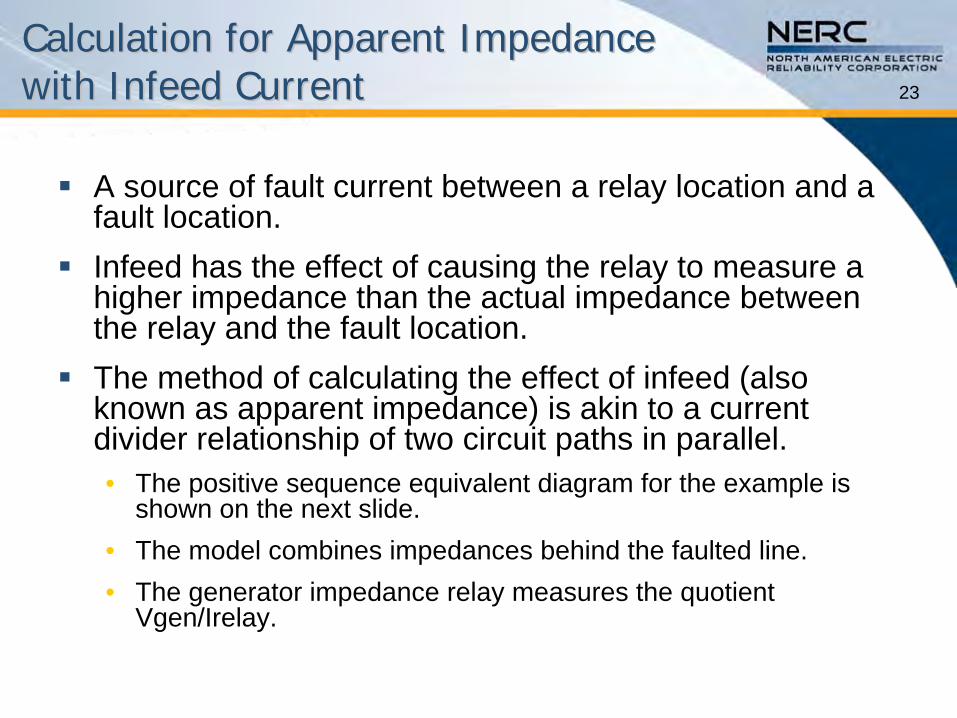
A source of fault current between a relay location and a fault location.
Infeed has the effect of causing the relay to measure a higher impedance than the actual impedance between the relay and the fault location.
The method of calculating the effect of infeed (also known as apparent impedance) is akin to a current divider relationship of two circuit paths in parallel. •
The positive sequence equivalent diagram for the example is shown on the next slide.
•
The model combines impedances behind the faulted line. •
The generator impedance relay measures the quotient Vgen/Irelay.
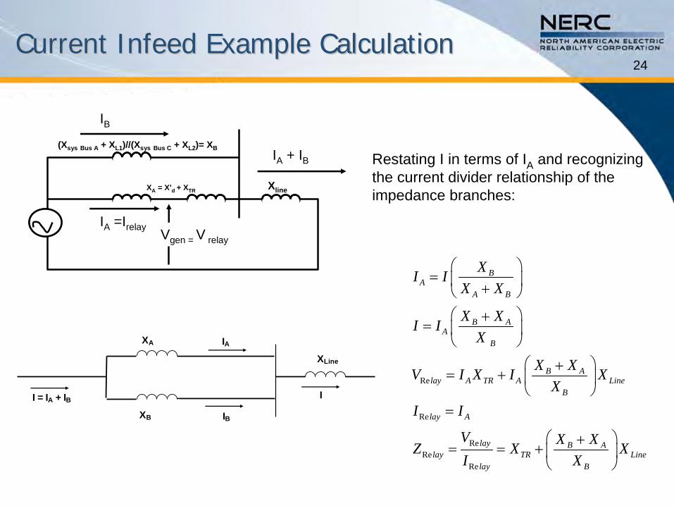
24Current Infeed Example CalculationCurrent Infeed Example Calculation
Xline
(Xsys Bus A + XL1)//(Xsys Bus C + XL2)= XB
XA = X’d + XTR
Vgen = V relay
IA =Irelay
IB
IA + IB
I = IA + IB I
IB
IA
XB
XA
XLine
Restating I in terms of IA
and recognizing the current divider relationship of the impedance branches:
Re
Re
ReRe
Re
BA
A B
B AA
B
B Alay A TR A Line
B
lay A
lay B Alay TR Line
lay B
XI IX X
X XI IX
X XV I X I XX
I I
V X XZ X XI X
25
Coordination of Generator and Coordination of Generator and Transmission System Transmission System –– Function 21Function 21
Coordination with Breaker Failure •
The 21 relay will detect transmission system faults that normally will be cleared by the transmission system relays.
•
The 21 relay time delay must be set to coordinate with the breaker failure clearing times with a reasonable margin. This requirement is necessary for all transmission protection zones (protected elements) within which the 21 relay can detect a fault.
•
For example, a 21 relay may detect a fault on a transmission line connected one bus away from the bus at which the generator is connected. Time coordination is needed should a transmission line fault and a breaker failure occur.
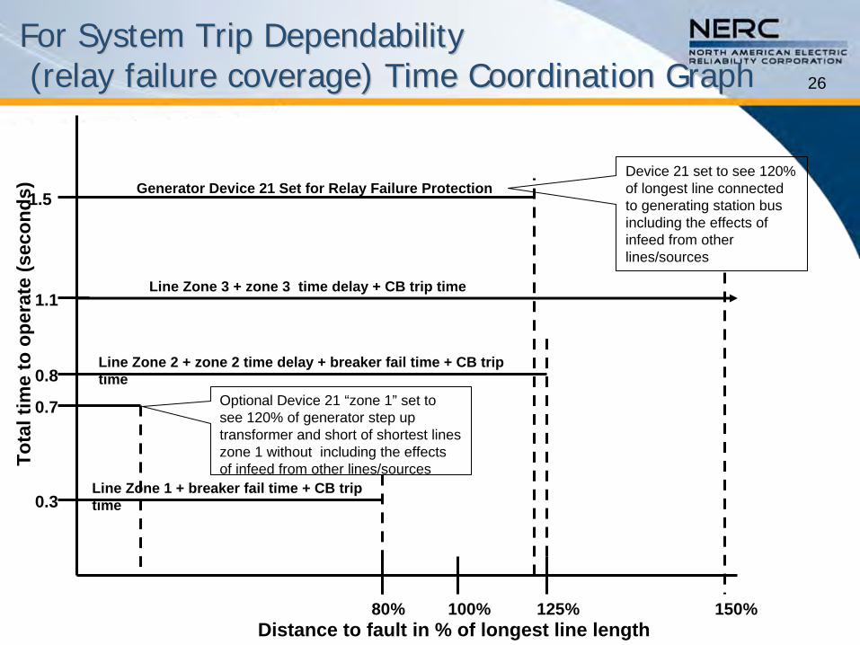
For System Trip DependabilityFor System Trip Dependability (relay failure coverage) Time Coordination Graph(relay failure coverage) Time Coordination Graph 26
Line Zone 1 + breaker fail time + CB trip time
Line Zone 2 + zone 2 time delay + breaker fail time + CB trip time
Line Zone 3 + zone 3 time delay + CB trip time
80% 100% 125% 150%Distance to fault in % of longest line length
0.3
1.5
1.1
0.8
Tota
l tim
e to
ope
rate
(sec
onds
)
0.7
Generator Device 21 Set for Relay Failure ProtectionDevice 21 set to see 120% of longest line connected to generating station bus including the effects of infeed from other lines/sources
Optional Device 21 “zone 1”
set to see 120% of generator step up transformer and short of shortest lines zone 1 without including the effects of infeed from other lines/sources
27
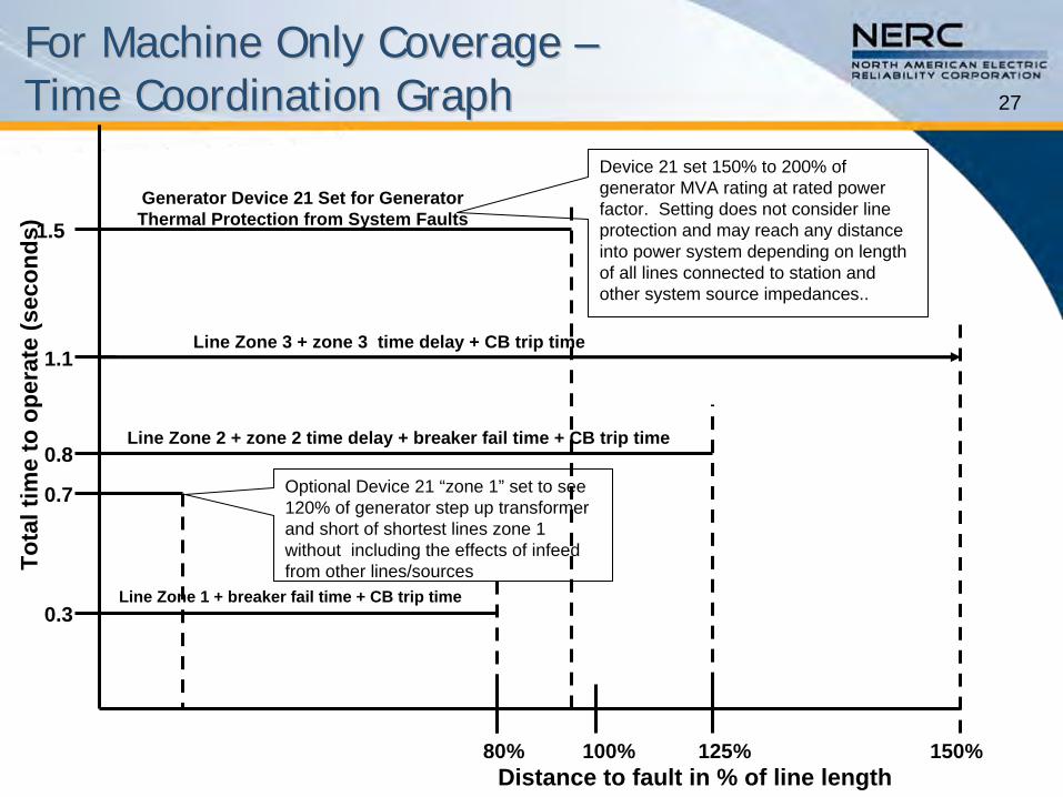
For Machine Only Coverage For Machine Only Coverage –– Time Coordination GraphTime Coordination Graph
Line Zone 1 + breaker fail time + CB trip time
Line Zone 2 + zone 2 time delay + breaker fail time + CB trip time
Line Zone 3 + zone 3 time delay + CB trip time
80% 100% 125% 150%Distance to fault in % of line length
0.3
1.5
1.1
0.8
Tota
l tim
e to
ope
rate
(sec
onds
)
0.7
Generator Device 21 Set for Generator Thermal Protection from System Faults
Optional Device 21 “zone 1”
set to see 120% of generator step up transformer and short of shortest lines zone 1 without including the effects of infeed from other lines/sources
Device 21 set 150% to 200% of generator MVA rating at rated power factor. Setting does not consider line protection and may reach any distance into power system depending on length of all lines connected to station and other system source impedances..
28Considerations and Issues Considerations and Issues –– Function 21Function 21
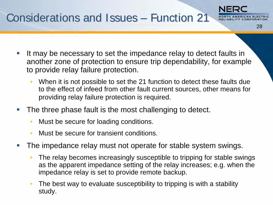
It may be necessary to set the impedance relay to detect faults in another zone of protection to ensure trip dependability, for example to provide relay failure protection.•
When it is not possible to set the 21 function to detect these faults due to the effect of infeed from other fault current sources, other means for providing relay failure protection is required.
The three phase fault is the most challenging to detect.•
Must be secure for loading conditions.
•
Must be secure for transient conditions.
The impedance relay must not operate for stable system swings.•
The relay becomes increasingly susceptible to tripping for stable swings as the apparent impedance setting of the relay increases; e.g. when the impedance relay is set to provide remote backup.
•
The best way to evaluate susceptibility to tripping is with a stability study.
29Coordination Procedure – Function 21
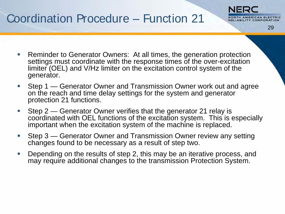
Reminder to Generator Owners: At all times, the generation protection settings must coordinate with the response times of the over-excitation limiter (OEL) and V/Hz limiter on the excitation control system of the generator.
Step 1 —
Generator Owner and Transmission Owner work out and agree on the reach and time delay settings for the system and generator protection 21 functions.
Step 2 —
Generator Owner verifies that the generator 21 relay is coordinated with OEL functions of the excitation system. This is especially important when the excitation system of the machine is replaced.
Step 3 —
Generator Owner and Transmission Owner review any setting changes found to be necessary as a result of step two.
Depending on the results of step 2, this may be an iterative process, and may require additional changes to the transmission Protection System.
30
Summary of Protection Functions Summary of Protection Functions Required for Coordination Required for Coordination –– Function 21Function 21
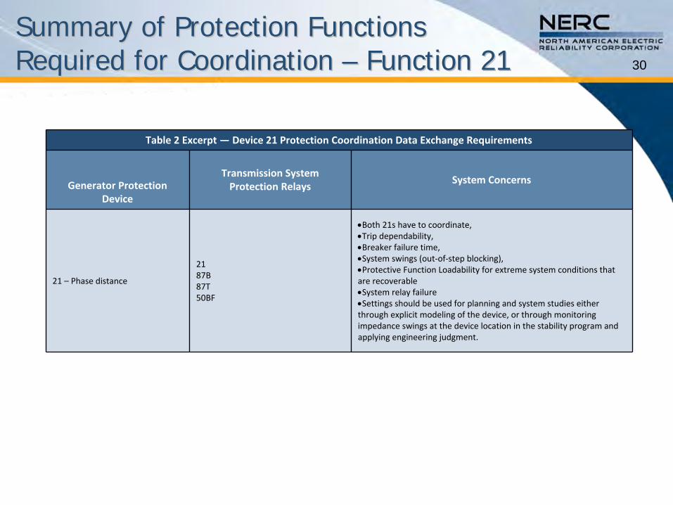
Table 2 Excerpt — Device 21 Protection Coordination Data Exchange Requirements
Generator Protection
Device
Transmission System
Protection RelaysSystem Concerns
21 – Phase distance
2187B87T50BF
Both 21s have to coordinate,Trip dependability, Breaker failure time, System swings (out‐of‐step blocking), Protective Function Loadability for extreme system conditions that
are recoverableSystem relay failureSettings should be used for planning and system studies either
through explicit modeling of the device, or through monitoring
impedance swings at the device location in the stability program
and
applying engineering judgment.
31
Protection Function Data and Information Exchange Required for Coordination – Function 21
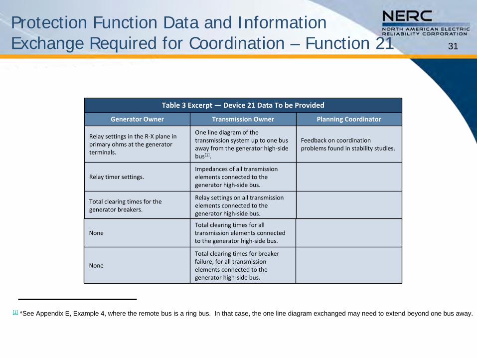
Table 3 Excerpt — Device 21 Data To be Provided
Generator Owner Transmission Owner Planning Coordinator
Relay settings in the R‐X plane in
primary ohms at the generator
terminals.
One line diagram of the
transmission system up to one bus
away from the generator high‐side
bus[1].
Feedback on coordination
problems found in stability studies.
Relay timer settings.Impedances of all transmission
elements connected to the
generator high‐side bus.
Total clearing times for the
generator breakers.
Relay settings on all transmission
elements connected to the
generator high‐side bus.
[1]
*See Appendix E, Example 4, where the remote bus is a ring bus.
In that case, the one line diagram exchanged may need to extend beyond one bus away.
NoneTotal clearing times for all
transmission elements connected
to the generator high‐side bus.
None
Total clearing times for breaker
failure, for all transmission
elements connected to the
generator high‐side bus.
32
VoltageVoltage--Controlled or Controlled or --Restrained Overcurrent Restrained Overcurrent –– Function 51VFunction 51V
Purpose•
Provide backup protection for system faults when the power system to which the generator is connected is protected by time-current coordinated protections.
33
VoltageVoltage--Controlled (51VControlled (51V--C) versusC) versus VoltageVoltage--Restrained (51CRestrained (51C--R) RelaysR) Relays
Voltage-Controlled Overcurrent Element (51V-C) •
In the voltage-controlled relay, a sensitive low pickup time-overcurrent relay is torque controlled by a voltage relay.
•
At normal and emergency operating voltage levels, the voltage relay is picked up and the relay is restrained from operating.
•
Under fault conditions, the voltage relay will drop out, thereby
permitting operation of the sensitive time-overcurrent relay.
Voltage-Restrained Overcurrent Element (51V-R) •
The characteristic of a voltage restrained overcurrent relay allows for a variable minimum pickup of the overcurrent element as determined
by the generator terminal voltage.
•
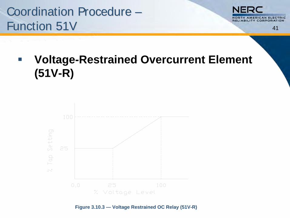
At 100 percent generator terminal voltage the overcurrent element will pickup at 100 percent of its pickup setting.
•
The minimum pickup of the overcurrent function decreases linearly with voltage until 25 percent or less when the minimum pickup of the overcurrent function is 25 percent of its minimum pickup setting.
34
VoltageVoltage--Controlled or VoltageControlled or Voltage--Restrained Restrained Overcurrent Overcurrent –– Function 51V Function 51V
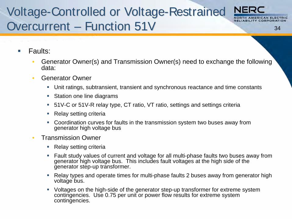
Faults:•
Generator Owner(s) and Transmission Owner(s) need to exchange the following data:
•
Generator Owner
Unit ratings, subtransient, transient and synchronous reactance and time constants
Station one line diagrams
51V-C or 51V-R relay type, CT ratio, VT ratio, settings and settings criteria
Relay setting criteria
Coordination curves for faults in the transmission system two buses away from generator high voltage bus
•
Transmission Owner
Relay setting criteria
Fault study values of current and voltage for all multi-phase faults two buses away from generator high voltage bus. This includes fault voltages at the
high side of the generator step-up transformer.
Relay types and operate times for multi-phase faults 2 buses away from generator high voltage bus.
Voltages on the high-side of the generator step-up transformer for extreme system contingencies. Use 0.75 per unit or power flow results for extreme system contingencies.
35
Coordination of Generator and Coordination of Generator and Transmission System Transmission System –– Function 51VFunction 51V
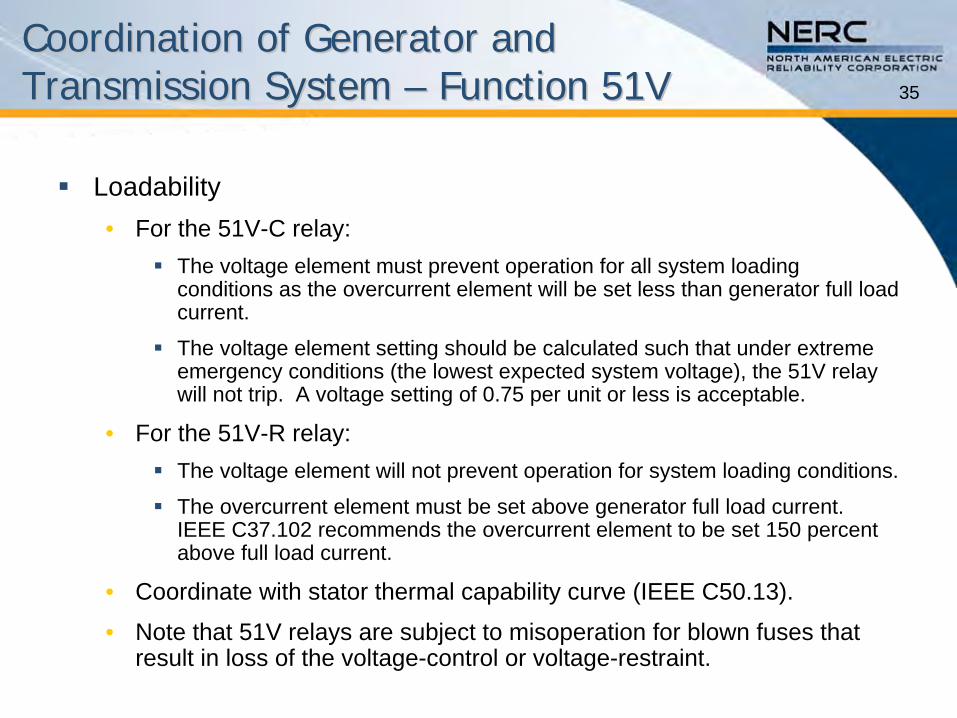
Loadability•
For the 51V-C relay:
The voltage element must prevent operation for all system loading conditions as the overcurrent element will be set less than generator full load current.
The voltage element setting should be calculated such that under
extreme emergency conditions (the lowest expected system voltage), the 51V relay will not trip. A voltage setting of 0.75 per unit or less is acceptable.
•
For the 51V-R relay:
The voltage element will not prevent operation for system loading conditions.
The overcurrent element must be set above generator full load current. IEEE C37.102 recommends the overcurrent element to be set 150 percent above full load current.
•
Coordinate with stator thermal capability curve (IEEE C50.13).
•
Note that 51V relays are subject to misoperation for blown fuses
that result in loss of the voltage-control or voltage-restraint.
36
Coordination of Generator and Coordination of Generator and Transmission System Transmission System –– Function 51VFunction 51V
Considerations and Issues•
For trip dependability within the protected zone, the current portion of the function must be set using fault currents obtained by modeling the generator reactance as its synchronous reactance.
•
To set the current portion of the relay to detect faults within the protected zone, the minimum pickup of the current element will be less than maximum machine load current. The protected zone can be defined as:
Provide backup generator protection for prolonged multi-phase fault within the generator step up transformer (GSU), the high voltage
bus, and a portion of a faulted transmission line, which has not
been isolated by primary system relaying.
•
The undervoltage element is the security aspect of the 51V-C function. C37.102 states (emphasis added):
“The 51V voltage element setting should be calculated such that under extreme emergency conditions (the lowest expected system voltage), the 51V relay will not trip.”
37
Coordination of Generator and Coordination of Generator and Transmission System Transmission System –– Function 51VFunction 51V
Considerations and Issues•
Seventy five percent of rated voltage is considered acceptable to avoid 51V operation during extreme system conditions.
A fault study must be performed to assure that this setting has reasonable margin for the faults that are to be cleared by the 51V.
Backup clearing of system faults is not totally dependent on a 51V relay (or 21 relay).
The 51V function has limited sensitivity and must not be relied upon to operate to complete an isolation of a system fault when a circuit breaker fails to operate.
The 51V has a very slow operating time for multi-phase faults. This may lead to local system instability resulting in the tripping of generators in the area.
•
Phase distance (impedance) relays should be coordinated with phase impedance relays –
inverse time-current relays should be coordinated with inverse time-
current relays.
Time coordinating a 51V and a 21 lends to longer clearing times at lower currents.
•
It is not necessary to have both functions enabled in a multi-function relay. The 21 function can clearly define its zone of protection and clearly define its time to operate and therefore coordinate better with transmission system
distance protection functions.
38
Coordination of Generator and Coordination of Generator and Transmission System Transmission System –– Function 51VFunction 51V
Special Considerations for Older Generators with Low Power Factors and Rotating Exciters •
Older low power factor machines that have slower-responding rotating exciters present an additional susceptibility to tripping for the following reasons:
•
The relatively low power factor (0.80 to 0.85) results in very high reactive current components in response to the exciter trying to
support the system voltage.
•
The slower response of the rotating exciters in both increasing and decreasing field current in those instances results in a longer time that the 51V element will be picked up, which increases the chances for tripping by the 51V.
•
If it is impractical to mitigate this susceptibility, Transmission Owners, Transmission Operators, Planning Coordinators, and Reliability Coordinators should recognize this generator tripping susceptibility in their system studies.
39
Coordination Procedure Coordination Procedure –– Function 51VFunction 51V
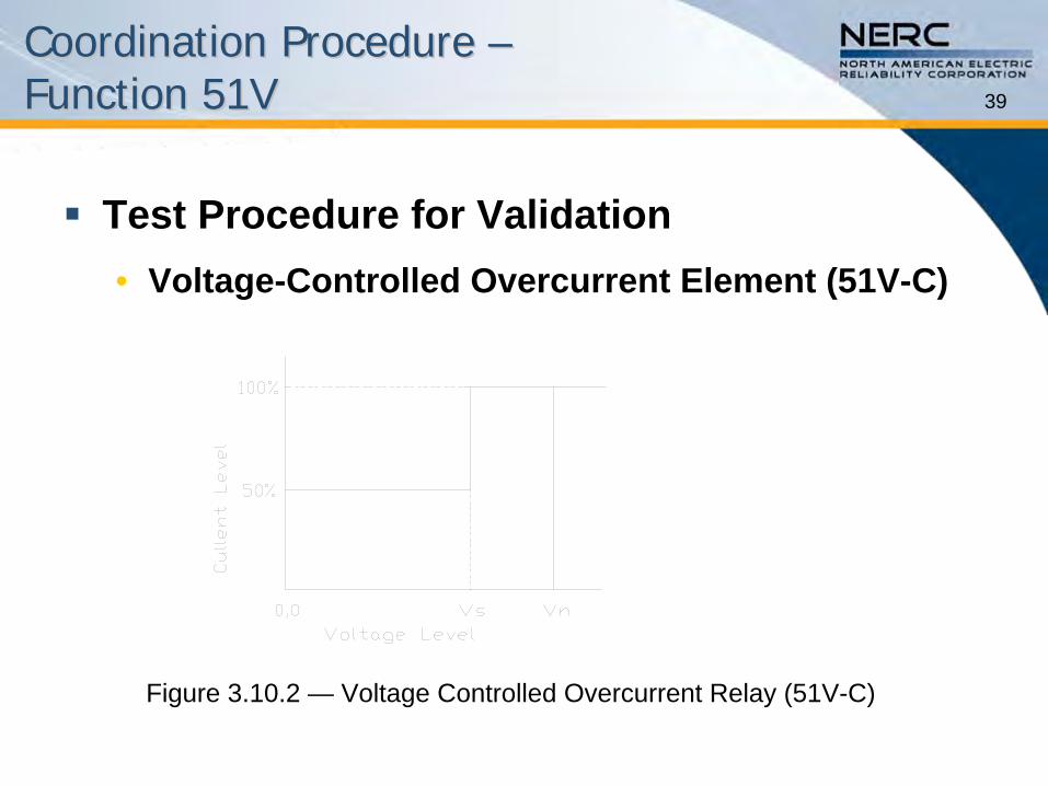
Test Procedure for Validation•
Voltage-Controlled Overcurrent Element (51V-C)
Figure 3.10.2 —
Voltage Controlled Overcurrent Relay (51V-C)
40
Coordination Procedure Coordination Procedure –– Function 51VFunction 51V
Voltage-Controlled Overcurrent Element (51V-C) •
Overcurrent pickup is usually set at 50 percent of generator full load current as determined by maximum real power out and exciter at maximum field forcing.
•
Undervoltage element should be set to dropout (enable overcurrent relay) at 0.75 per unit generator terminal voltage or less.
•
Overcurrent element should not start timing until undervoltage element drops out.
•
Time coordination must be provided for all faults on the high side of the GSU including breaker failure time and an agreed upon reasonable margin. Time coordination must also include zone 2 clearing times for a fault just beyond zone 1 for the shortest transmission line unless there are calculations to prove that the 51V will not operate beyond zone 1 with reasonable margin (typically 0.4 s to 0.5 s).
41
Coordination Procedure Coordination Procedure –– Function 51VFunction 51V
Voltage-Restrained Overcurrent Element (51V-R)
Figure 3.10.3 —
Voltage Restrained OC Relay (51V-R)
42
Coordination Procedure Coordination Procedure –– Function 51VFunction 51V
Voltage-Restrained Overcurrent Element (51V-R)•
The 100 percent setting for the voltage setpoint must be at 0.75
per unit terminal voltage or less.
•
Determine an agreed upon margin for trip dependability (determine relay voltage for a fault on the terminal of the GSU). The voltage function should not drop out for extreme system contingencies (0.85 per unit GSU terminal voltage and generator at maximum real power out and exciter at maximum field forcing).
•
Time coordination must be provided for all faults on the high side of the GSU including breaker failure time and an agreed upon reasonable margin. Time coordination must also include zone 2 clearing times for a fault just beyond zone 1 for the shortest transmission line unless there are calculations to prove that the 51V will not operate beyond zone 1 with reasonable margin (typically 0.4 s to 0.5 s).
43
Coordination of Generator and Coordination of Generator and Transmission System Transmission System –– Function 51VFunction 51V
Setting Considerations •
For the 51V-C relay, the voltage element must prevent operation for all system loading conditions as the overcurrent element will be set less than generator full load current. The voltage element setting should be calculated such that under extreme emergency conditions (the lowest expected system voltage), the 51V relay will not trip. A voltage setting of 0.75 per unit or less is acceptable.
•
For the 51V-R relay, the voltage element will not prevent operation for system loading conditions. The overcurrent element must be set above generator full load current. IEEE C37.102 recommends the overcurrent element to be set 150 percent above full load current. (For some applications a higher setting may be necessary.)
44
Example Example –– Proper CoordinationProper Coordination –– Function 51VFunction 51V
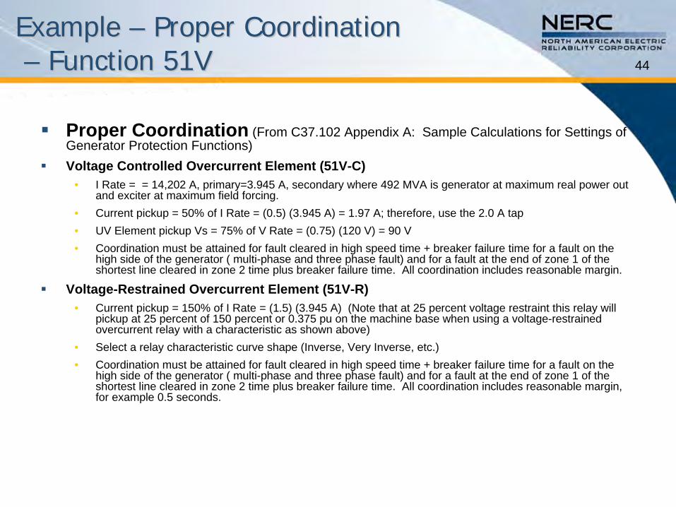
Proper Coordination
(From C37.102 Appendix A: Sample Calculations for Settings of Generator Protection Functions)
Voltage Controlled Overcurrent Element (51V-C)•
I Rate = = 14,202 A, primary=3.945 A, secondary where 492 MVA is generator at maximum real power out and exciter at maximum field forcing.
•
Current pickup = 50% of I Rate = (0.5) (3.945 A) = 1.97 A; therefore, use the 2.0 A tap•
UV Element pickup Vs = 75% of V Rate = (0.75) (120 V) = 90 V•
Coordination must be attained for fault cleared in high speed time + breaker failure time for a fault on the high side of the generator ( multi-phase and three phase fault) and for a fault at the end of zone 1 of the shortest line cleared in zone 2 time plus breaker failure time. All coordination includes reasonable margin.
Voltage-Restrained Overcurrent Element (51V-R)•
Current pickup = 150% of I Rate = (1.5) (3.945 A) (Note that at
25 percent voltage restraint this relay will pickup at 25 percent of 150 percent or 0.375 pu on the machine base when using a voltage-restrained overcurrent relay with a characteristic as shown above)
•
Select a relay characteristic curve shape (Inverse, Very Inverse, etc.)•
Coordination must be attained for fault cleared in high speed time + breaker failure time for a fault on the high side of the generator ( multi-phase and three phase fault) and for a fault at the end of zone 1 of the shortest line cleared in zone 2 time plus breaker failure time. All coordination includes reasonable margin, for example 0.5 seconds.
45
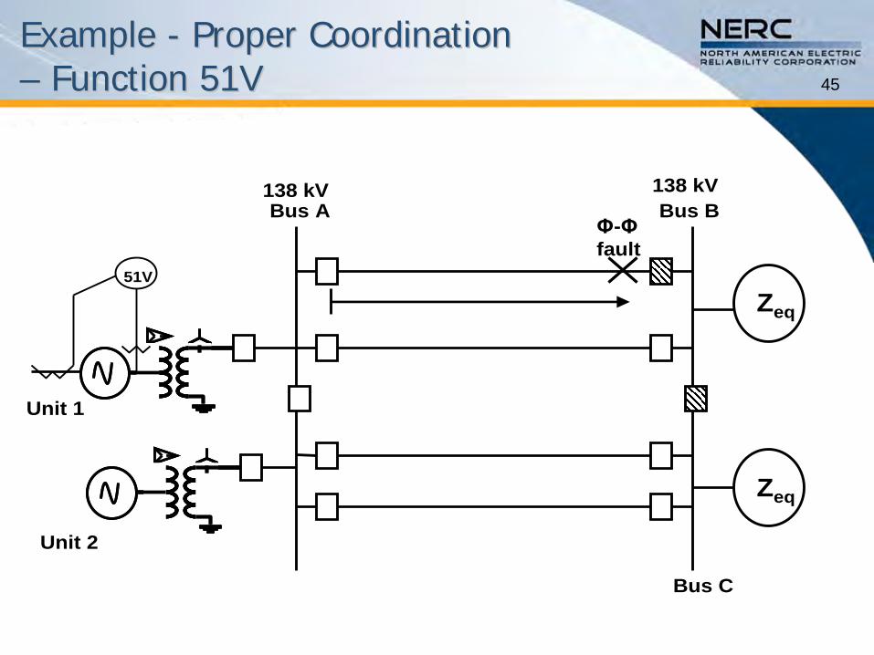
Example Example -- Proper Coordination Proper Coordination –– Function 51VFunction 51V
Zeq
Zeq
Bus A
Bus C
Bus B
Unit 1
Φ-Φfault
138 kV 138 kV
Unit 2
51V
46
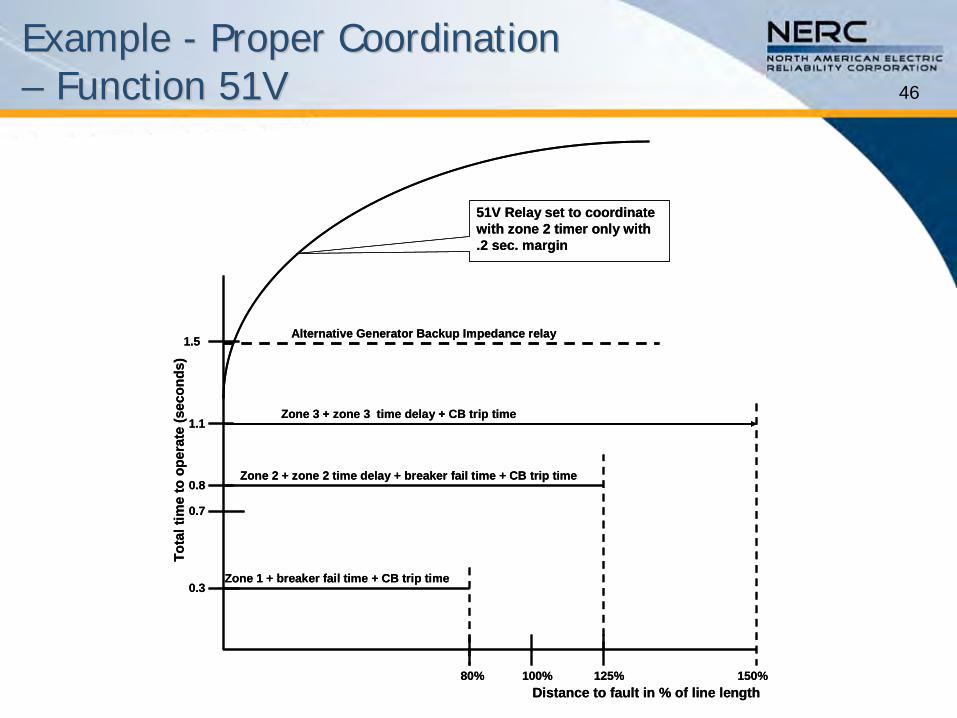
Example Example -- Proper Coordination Proper Coordination –– Function 51VFunction 51V
Zone 1 + breaker fail time + CB trip time
Zone 2 + zone 2 time delay + breaker fail time + CB trip time
Zone 3 + zone 3 time delay + CB trip time
80% 100% 125% 150%Distance to fault in % of line length
0.3
1.5
1.1
0.8
Tota
l tim
e to
ope
rate
(sec
onds
)
51V Relay set to coordinate with zone 2 timer only with .2 sec. margin
0.7
Alternative Generator Backup Impedance relay
47
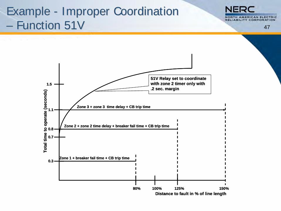
Example Example -- Improper Coordination Improper Coordination –– Function 51VFunction 51V
Zone 1 + breaker fail time + CB trip time
Zone 2 + zone 2 time delay + breaker fail time + CB trip time
Zone 3 + zone 3 time delay + CB trip time
80% 100% 125% 150%Distance to fault in % of line length
0.3
1.5
1.1
0.8
Tota
l tim
e to
ope
rate
(sec
onds
)
51V Relay set to coordinate with zone 2 timer only with .2 sec. margin
0.7
48
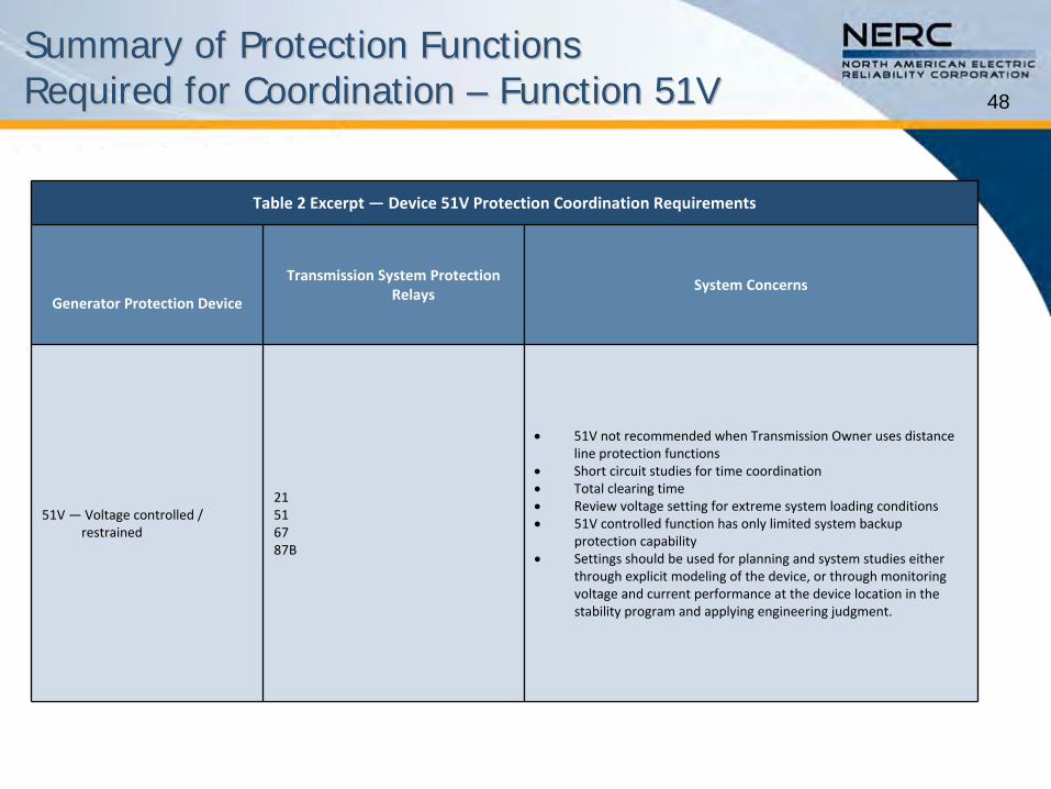
Summary of Protection Functions Summary of Protection Functions Required for Coordination Required for Coordination –– Function 51VFunction 51V
Table 2 Excerpt — Device 51V Protection Coordination Requirements
Generator Protection Device
Transmission System Protection
RelaysSystem Concerns
51V —Voltage controlled /
restrained
21516787B
51V not recommended when Transmission Owner uses distance
line protection functions
Short circuit studies for time coordination
Total clearing time
Review voltage setting for extreme system loading conditions
51V controlled function has only limited system backup
protection capability
Settings should be used for planning and system studies either
through explicit modeling of the device, or through monitoring
voltage and current performance at the device location in the
stability program and applying engineering judgment.
49
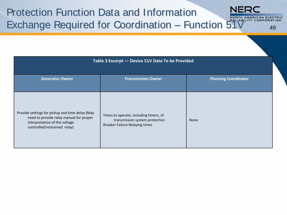
Protection Function Data and Information Protection Function Data and Information Exchange Required for Coordination Exchange Required for Coordination –– Function 51VFunction 51V
Table 3 Excerpt — Device 51V Data To be Provided
Generator Owner Transmission Owner Planning Coordinator
Provide settings for pickup and time delay (May
need to provide relay manual for proper
interpretation of the voltage
controlled/restrained relay)
Times to operate, including timers, of
transmission system protectionBreaker Failure Relaying times
None
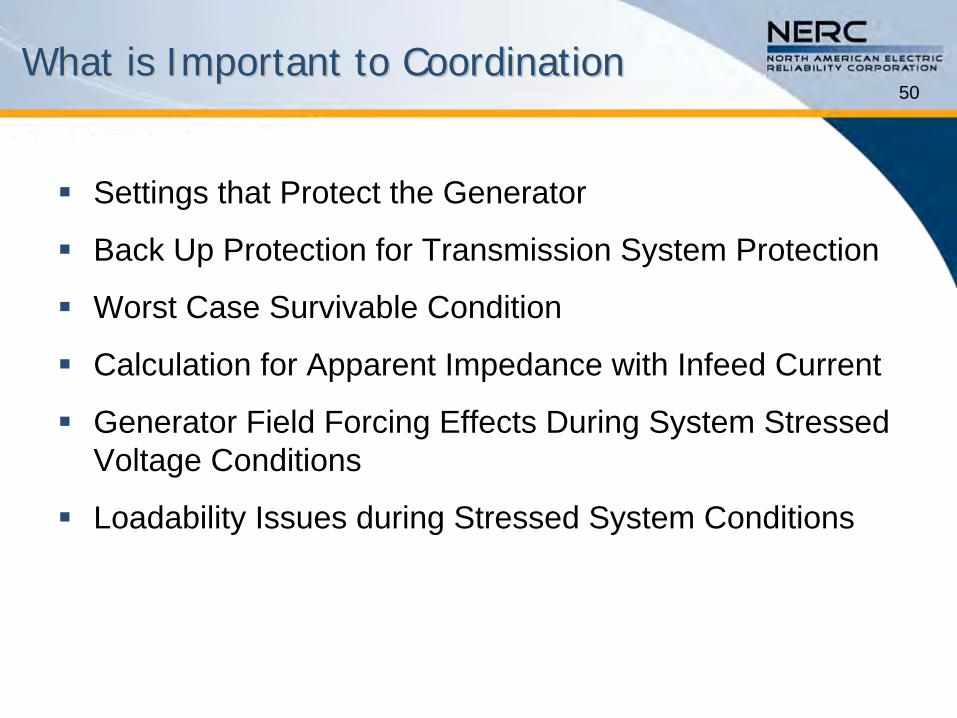
50What is Important to CoordinationWhat is Important to Coordination
Settings that Protect the Generator
Back Up Protection for Transmission System Protection
Worst Case Survivable Condition
Calculation for Apparent Impedance with Infeed Current
Generator Field Forcing Effects During System Stressed Voltage Conditions
Loadability Issues during Stressed System Conditions
51Settings that Protect the GeneratorSettings that Protect the Generator
The generator protection set-points are described in the IEEE Guide for AC Generator Protection (C37.102) for both Functions 21 and 51V based on machine -
system reactance and
characteristics.
The previous examples illustrated the set point calculations.
52
BackBack--Up for Up for Transmission System ProtectionTransmission System Protection
Providing back-up for transmission system protection requires careful analysis and a balance between tripping security and dependability.
These coordination concepts were discussed and illustrated in this presentation.
Undesired tripping during system stressed conditions that are survivable must be avoided to maintain a reliable Bulk Electric System.
53Worst Case Survivable ConditionWorst Case Survivable Condition
The protection must be set to avoid unnecessary tripping for worst case survivable conditions:•
Operation of transmission equipment within continuous and emergency thermal and voltage limits
•
Recovery from a stressed system voltage condition for an extreme
system event –
i.e. 0.85 pu voltage at the system high side of the generator step-up transformer
•
Stable power swings
•
Transient frequency and voltage conditions for which UFLS and UVLS programs are designed to permit system recovery
When coordination cannot be achieved without compromising protection of the generator, the generator protection setting must be accounted for in system studies.