Embed Size (px)
Citation preview
Sava
nnah
Riv
er S
ite
Liqu
id W
aste
Pla
nnin
g Pr
oces
s
REVISION 18June 2013
An In
tegr
ated
Sys
tem
at t
he S
avan
nah
Rive
r Sit
e
SRR-LWP-2009-00001
LLIQUID Waste System Plan
IQUID Waste System Plan


Savannah River Remediation LLC Savannah River Site Aiken, SC 29808
Prepared for U.S. Department of Energy under Contract No. DE-AC09-09SR22505
SRR-LWP-2009-00001 REVISION: 18 June 24, 2013 KEYWORDS: Tank Farm, Salt Program DWPF, Liquid Waste ETF, Sludge Washing Lifecycle, Waste Solidification MCU, ARP, CSSX, SWPF RETENTION: PERMANENT
Liquid Waste System Plan Revision 18
D. P. Chew
B. A. Hamm
Approvals:
__________________________________________ L. David Olson
SRR President & Project Manager
__________________________________________ Terrel J. Spears
Assistant Manager for Waste Disposition Project

SRR-LWP-2009-00001 Liquid Waste System Plan June 24, 2013 Revision 18
Page ii
Authors __________________________________________________________________ D. P. Chew, System Planning __________________________________________________________________ B. A. Hamm, System Planning
Reviews
__________________________________________________________________ L. T. Ling, Manager, System Planning __________________________________________________________________ R.W. Blackmon, Manager, Project Integration, and Planning

Liquid Waste System Plan SRR-LWP-2009-00001 Revision 18 June 24, 2013
Page iii
.Table of Contents 1. EXECUTIVE SUMMARY ...........................................................................................................1
PURPOSE ................................................................................................................................................................... 1 COMMON GOALS & VALUES .................................................................................................................................. 2 GOALS ....................................................................................................................................................................... 2 REVISIONS ................................................................................................................................................................ 3 RESULTS OF THE PLAN ........................................................................................................................................... 3
2. INTRODUCTION .......................................................................................................................5 2.1 COMMON GOALS & VALUES ...................................................................................................................... 5 2.2 GOALS ........................................................................................................................................................... 7 2.3 ALTERNATIVE ANALYSES ........................................................................................................................ 11 2.4 RISK ASSESSMENT ..................................................................................................................................... 11
3. PLANNING BASES ..................................................................................................................12 3.1 FUNDING ..................................................................................................................................................... 12 3.2 REGULATORY DRIVERS ............................................................................................................................ 12 3.3 REVISIONS .................................................................................................................................................. 13 3.4 KEY MILESTONES ...................................................................................................................................... 14
4. PLANNING SUMMARY AND RESULTS ..................................................................................15 4.1 DISPOSITION OF SLUDGE WASTE ............................................................................................................ 15 4.2 DWPF OPERATIONS ................................................................................................................................... 16 4.3 DISPOSITION OF SALT WASTES ................................................................................................................ 18
4.3.1 Actinide Removal Process / Modular CSSX Unit (APR/MCU) .................................................. 19 4.3.2 Small Column Ion Exchange (SCIX) .......................................................................................... 22 4.3.3 Salt Waste Processing Facility (SWPF) ..................................................................................... 23
4.4 SALTSTONE OPERATIONS ......................................................................................................................... 25 4.5 WASTE REMOVAL AND TANK CLOSURE ................................................................................................ 25
4.5.1 Waste Removal and Tank Cleaning ............................................................................................ 25 4.5.2 Tank Closure and Stabilization .................................................................................................. 28
4.6 BASE OPERATIONS .................................................................................................................................... 29 4.6.1 Supporting Nuclear Material Stabilization ................................................................................ 29 4.6.2 DWPF Recycle Handling ........................................................................................................... 30 4.6.3 Transfer Line Infrastructure ....................................................................................................... 30 4.6.4 Tank 50 Equipping for HLW Service .......................................................................................... 30 4.6.5 Effluent Treatment Facility ......................................................................................................... 30 4.6.6 Managing Type III Tank Space .................................................................................................. 31
4.7 CLOSURE SEQUENCE FOR THE LIQUID WASTE SYSTEM ....................................................................... 31
5. ALTERNATIVE ANALYSES ....................................................................................................33 5.1 2023 SWPF STARTUP ................................................................................................................................. 33
6. DESCRIPTION OF ASSUMPTIONS AND BASES .....................................................................34 6.1 PRIORITIES FOR PLAN DEVELOPMENT .................................................................................................... 34 6.2 FUNDING ..................................................................................................................................................... 34 6.3 REGULATORY DRIVERS ............................................................................................................................ 34 6.4 WASTE REMOVAL AND TANK REMOVAL FROM SERVICE PROGRAM ................................................. 34 6.5 DWPF PRODUCTION .................................................................................................................................. 35 6.6 SALT PROGRAM ......................................................................................................................................... 36 6.7 SALTSTONE PRODUCTION ........................................................................................................................ 38 6.8 BASE OPERATIONS .................................................................................................................................... 38
7. SYSTEM DESCRIPTION .........................................................................................................40 7.1 HISTORY ..................................................................................................................................................... 40 7.2 TANK STORAGE ......................................................................................................................................... 40 7.3 WASTE TANK SPACE MANAGEMENT ...................................................................................................... 42 7.4 WASTE REMOVAL FROM TANKS.............................................................................................................. 43 7.5 SAFE DISPOSAL OF THE WASTE ............................................................................................................... 44 7.6 SALT PROCESSING ..................................................................................................................................... 44
SRR-LWP-2009-00001 Liquid Waste System Plan June 24, 2013 Revision 18
Page iv
7.7 SLUDGE PROCESSING ................................................................................................................................ 45 7.8 DWPF VITRIFICATION ............................................................................................................................... 45 7.9 SALTSTONE DISPOSITION ......................................................................................................................... 45
APPENDIX A — SALT SOLUTION PROCESSING, BASE CASE .......................................................50 APPENDIX B — SLUDGE PROCESSING .........................................................................................51 APPENDIX C — CANISTER STORAGE ...........................................................................................52 APPENDIX D — BWRE & REMOVAL FROM SERVICE, BASE CASE .............................................53 APPENDIX E — TANK FARM INFLUENTS AND EFFLUENTS .......................................................54 APPENDIX F — REMAINING TANK INVENTORY ..........................................................................56 APPENDIX G — LW SYSTEM PLAN — REV 18 SUMMARY ..........................................................57 APPENDIX H — SALT SOLUTION PROCESSING, ALTERNATE CASE............................................58 APPENDIX I — BWRE & REMOVAL FROM SERVICE, ALTERNATE CASE ...................................59 APPENDIX J — ACRONYMS ..........................................................................................................60 REFERENCES .................................................................................................................................62
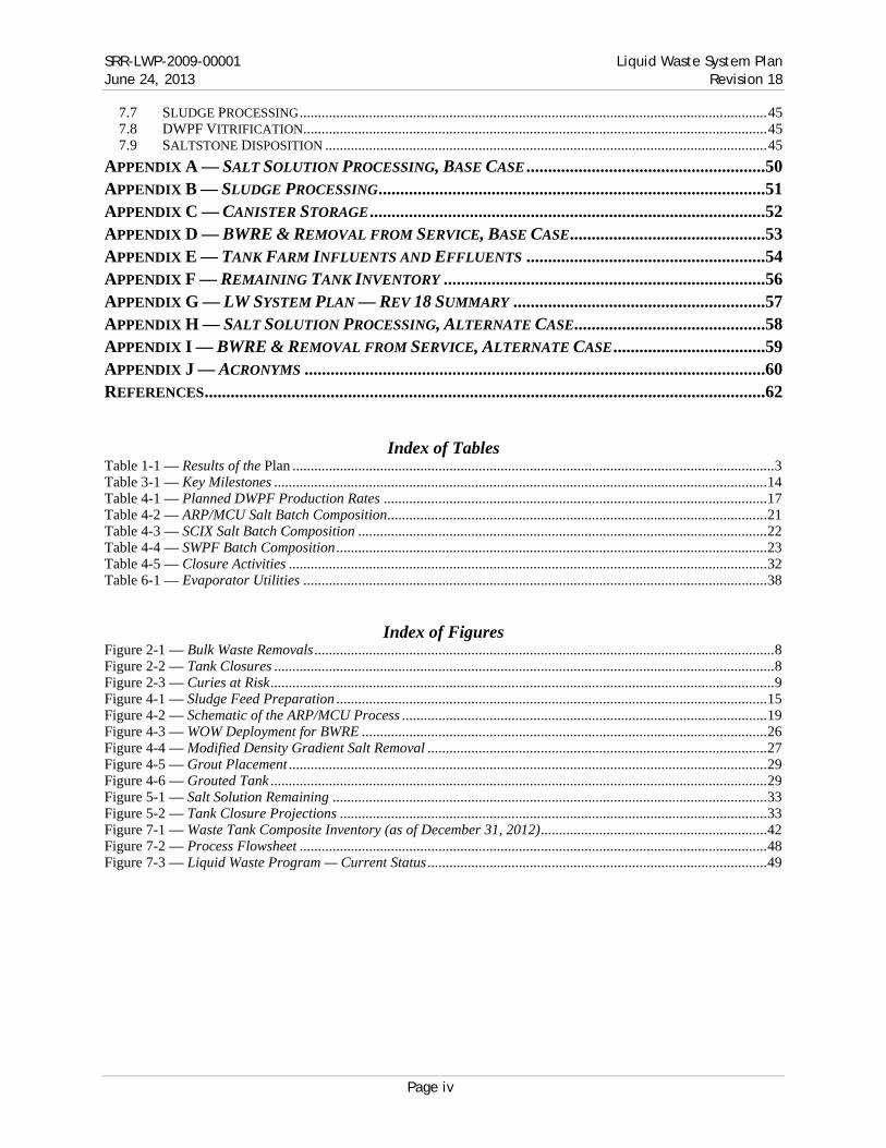
Index of Tables Table 1-1 — Results of the Plan .................................................................................................................................... 3 Table 3-1 — Key Milestones ....................................................................................................................................... 14 Table 4-1 — Planned DWPF Production Rates ......................................................................................................... 17 Table 4-2 — ARP/MCU Salt Batch Composition ........................................................................................................ 21 Table 4-3 — SCIX Salt Batch Composition ................................................................................................................ 22 Table 4-4 — SWPF Batch Composition ...................................................................................................................... 23 Table 4-5 — Closure Activities ................................................................................................................................... 32 Table 6-1 — Evaporator Utilities ............................................................................................................................... 38
Index of Figures Figure 2-1 — Bulk Waste Removals .............................................................................................................................. 8 Figure 2-2 — Tank Closures ......................................................................................................................................... 8 Figure 2-3 — Curies at Risk .......................................................................................................................................... 9 Figure 4-1 — Sludge Feed Preparation ...................................................................................................................... 15 Figure 4-2 — Schematic of the ARP/MCU Process .................................................................................................... 19 Figure 4-3 — WOW Deployment for BWRE ............................................................................................................... 26 Figure 4-4 — Modified Density Gradient Salt Removal ............................................................................................. 27 Figure 4-5 — Grout Placement ................................................................................................................................... 29 Figure 4-6 — Grouted Tank ........................................................................................................................................ 29 Figure 5-1 — Salt Solution Remaining ....................................................................................................................... 33 Figure 5-2 — Tank Closure Projections ..................................................................................................................... 33 Figure 7-1 — Waste Tank Composite Inventory (as of December 31, 2012) .............................................................. 42 Figure 7-2 — Process Flowsheet ................................................................................................................................ 48 Figure 7-3 — Liquid Waste Program — Current Status ............................................................................................. 49

Liquid Waste System Plan SRR-LWP-2009-00001 Revision 18 June 24, 2013
Page 1 Executive Summary
1. Executive Summary
Treatment and disposition of salt waste is the critical path to completion of the Savannah River Site (SRS) Liquid Waste (LW) Disposition Program. During the period prior to startup of the Salt Waste Processing Facility (SWPF), salt waste disposition will continue through the Actinide Removal Process (ARP) and Modular Caustic Side Solvent Extraction (CSSX) Unit (MCU) facilities. Deliquification, Dissolution and Adjustment (DDA) processing was required prior to startup of the ARP/MCU facilities to enable continued tank closure activities, to sustain sludge disposition activities in the Defense Waste Processing Facility (DWPF), and to minimize continued limited use of old-style tanks. During the DDA phase, approximately 2.8 million gallons of dissolved salt solution from Tank 41 and associated adjustment streams were dispositioned. Another 3.2 million gallons of salt waste have been dispositioned through ARP/MCU since startup in April 2008.
With the December 2010 Revision 16 of the Liquid Waste System Plan1 (hereinafter referred to as the “Plan”) DOE summarized a comprehensive, integrated program execution strategy for optimized LW system performance. Revision 16 of the System Plan included deployment of several new technologies such as:
● Small Column Ion Exchange (SCIX) to supplement the salt waste treatment capabilities of ARP/MCU and SWPF
● Enhanced chemical cleaning of tanks after the bulk waste removal efforts (BWRE) are complete ● Melter bubbler technology to improve the capacity of the DWPF melter ● DWPF feed preparation improvements to reduce processing time within DWPF ● Rotary microfiltration (RMF) to decrease sludge preparation cycle time ● Low temperature aluminum dissolution (LTAD) of sludge to minimize DWPF canister count ● Optimization of the tank closure process to enable a reduction in the tank closure process cycle time.
These actions would have resulted in maximizing sludge and salt processing, doubling DWPF throughput, closing old-style tanks ahead of the schedule required by regulatory agreements, and accelerating completion of the program lifecycle.
The February 2012 Revision 172 of the Plan included updated inputs and assumptions. The primary constraints which limit program execution per the accelerated Revision 16 pathway are, first, funding targets significantly below previously assumed levels and, second, realignment of the SWPF Project schedule. Revision 17 still projected tank closures and program completion on or ahead of regulatory commitments, albeit on a “just-in-time” basis for most activities.
This eighteenth revision of the Plan recognizes challenges from the further delay of SWPF and its concomitant effect on regulatory milestones. It also recognizes additional challenges in funding. Preliminary funding guidance for Fiscal Year 2014 (FY14) and projections for future years are significantly less than needed to execute the mission as outlined in Revision 17 of the Plan. These reduced funding levels combined with further delay in the SWPF drove the need for a revised approach. The President’s Budget Request (PBR), however, was submitted after the development of this plan. Therefore, the impacts to the LW program from the PBR are not reflected in this Plan This Plan mitigates the effect of these challenges by continuing to reinvent the SRS LW Program in a way that integrates the smartest combination of facility operating schedules, supporting infrastructure upgrades, and workforce management actions to enable the completion of as many deliverables as possible under reduced budget projections. The overarching objective of this Plan is to ensure safe storage of the waste and minimize extension of the remaining time at risk associated with legacy high level waste storage in aging tanks.
Equally important is timely approval of major scope items (e.g., Saltstone Disposal Unit #6 (SDU-6) and following, Small Column Ion Exchange, additional Glass Waste Storage, etc.). This Plan assumes the availability of these facilities that require multi-year construction projects and approvals well before the need date. Delay in approving these major scope items will interfere with the accomplishment of the goals of this Plan.
Safe storage, risk reduction, and provision of necessary facilities are essential precursors to successful closure of waste tanks.
Purpose
The purpose of this Plan is to integrate and document the activities required to disposition the existing and future High Level Waste (HLW) and to remove from service radioactive LW tanks and facilities at the Department of Energy (DOE) at SRS. It records a planning basis for waste processing in the LW System through the end of the

SRR-LWP-2009-00001 Liquid Waste System Plan June 24, 2013 Revision 18
Executive Summary Page 2
program mission. Development of this Plan is a joint effort between DOE-Savannah River (DOE-SR) and Savannah River Remediation LLC (SRR).
This Plan satisfies the contract deliverable described in Contract No DE-AC09-09SR22505; Part III — List of Documents, Exhibits, and Other Attachments; Section J — List of Attachments; Appendix M — Deliverables; Item No 1 — Liquid Waste System Plan.3
This eighteenth revision (Revision 18) of the Plan: ● Provides one of the inputs to development of financial submissions to the complex-wide Integrated Planning,
Accountability, & Budgeting System (IPABS) ● Provides a basis for LW contract and Contract Performance Baseline changes.
Common Goals & Values
The overarching principles which govern strategic planning and execution of the SRS Liquid Waste Disposition Program are summarized well in the seven “Common Goals and Values” that were agreed upon by key stakeholders almost a decade ago. These remain the guiding goals and values for program execution and planning: 1. Reduce operational risk and the risk of leaks to the environment by removing waste from tanks, and closing the
tanks 2. Remove actinides from waste expeditiously since they impact on the environment most significantly if a leak
occurs. 3. Maximize amount of waste ready for disposal in deep geologic repository. Make significant effort to ensure
maximum amount of long lived radionuclides are disposed in a deep geologic repository. 4. Remove as much cesium as practical from salt waste and dispose in parallel with vitrified sludge. 5. Dispose of cesium as soon as practical to avoid having cesium only waste when sludge vitrification is complete. 6. Limit disposal of radioactive waste onsite at SRS so that residual radioactivity is as low as reasonably
achievable. 7. Ensure DOE’s strategy and plans are subject to public involvement and acceptance.
Goals
The goals of previous revisions of this Plan, through Revision 17, have always been to meet Federal Facility Agreement (FFA)4 and Site Treatment Plan (STP)5 regulatory commitments. However, with the delays of SWPF beyond October 2014, as demonstrated in Revision 17, these regulatory commitments have been adversely affected:
● Meet tank bulk waste removal efforts regulatory milestones in the currently-approved FFA ● Meet tank removal-from-service regulatory milestones in the currently-approved FFA ● Meet the waste treatment goals identified in the STP
The goals of this Plan, then, are to meet the following programmatic objectives: ● Continue storing liquid radioactive wastes in a safe and environmentally sound manner ● Optimize program life cycle cost and schedule to minimize extension of the remaining time-at-risk associated
with legacy high level waste storage in aging tanks ● Conduct operations consistent with the Section 3116 Determination for Salt Waste Disposal at the Savannah
River Site6, the Basis for Section 3116 Determination for Salt Waste Disposal at the Savannah River Site7, the Section 3116 Determination for Closure of F-Tank Farm at the Savannah River Site8, the Basis for Section 3116 Determination for Closure of F-Tank Farm at the Savannah River Site9, and future Waste Determination (WD) and Basis documents for H-Tank Farm
● Comply with applicable permits and consent orders, including the Modified Class 3 Landfill Permit for the SRS Z-Area Saltstone Disposal Facility (SDF) (permit ID 025500-1603) and State-approved area-specific General Closure Plans
● Provide tank space to support staging of salt solution adequate to feed the SWPF per the inputs and assumptions
● Provide tank space to support staging of salt solution adequate to feed the SCIX per the inputs and assumptions
● Sustain sludge vitrification in the DWPF ● Minimize the quantity of radionuclides (as measured in curies) dispositioned in the SDF, keeping the total
curies at or below the amount identified in Savannah River Site – Liquid Waste Disposition Processing Strategy10 (SRS LW Strategy), as amended by letter from the South Carolina Department of Health and

Liquid Waste System Plan SRR-LWP-2009-00001 Revision 18 June 24, 2013
Page 3 Executive Summary
Environmental Control (SCDHEC) to DOE-SR11 and the Basis for Section 3116 Determination for Salt Waste Disposal at the Savannah River Site7
● Support continued nuclear material stabilization of legacy materials in H-Canyon.
To enable continuation of risk reduction initiatives encompassed by the goals above, this Plan follows a processing strategy to provide the tank space required to support meeting, or minimizing impacts to meeting, programmatic objectives. During the period prior to startup of SWPF in 2018, near-term retrieval, treatment, and disposal of salt waste are required. The ARP/MCU facilities provide this treatment. Operation of these salt treatment processes frees up working space in the 2F, 2H, and 3H Evaporators’ concentrate receipt tanks (Tanks 25, 38, and 30 and 37, respectively). This provides support for near-term handling of waste streams generated from early-year tank removals from service, DWPF sludge batch preparation, DWPF recycle handling, and H-Canyon processing.
Revisions
The significant updates from the previous version of this Plan, the Liquid Waste System Plan, Revision 17 (Rev 17)2, include:
● Modifications required due to near-term funding limitation: — Cancel Enhanced Chemical Cleaning (ECC) implementation — Reschedule implementation of SCIX — Delays in tank removal from service that are beyond FFA commitments for BWRE and operational
closure commitments ● Salt Processing:
— SWPF Processing: SWPF operations initiation delayed to October 2018 from October 2014 — SWPF Processing: SWPF maximum processing rate increased to 9 Mgal/yr from 8 Mgal/yr — SCIX Processing: reschedule of SRR’s proposal of a supplemental salt treatment process to April 2019
from October 2018 due to funding limitation — SCIX Processing: SCIX maximum processing rate increased to 3 Mgal/yr from 2.5 Mgal/yr.
● Sludge Processing — The nominal canister rate reduced to 275 from 325
Results of the Plan
Table 1-1 — Results of the Plan describes the major results as compared to Revision 17 of the Plan:
Table 1-1 — Results of the Plan Parameter Revision 17 This Plan
Date last LW facility removed from service 2028 2034 All bulk waste removal currently-approved FFA commitments met Yes No All yearly tank removal from service currently-approved FFA commitments met Yes No Final FY2022 currently-approved FFA commitment met Yes No Final Type I, II, and IV tanks removed from service 2022 2028 Complete bulk salt treatment 2026 2028 Complete bulk sludge treatment 2026 2026 Complete heel treatment 2028 2032 SCIX for supplemental salt waste treatment Yes Yes Next generation extractant for increased SWPF throughput Yes Yes Maximum canister waste loading 43 wt% 40 wt% Nominal annual canister throughput rate 325 275 Total number of canisters produced 7,580 7,824Radionuclides (curies) dispositioned in SDF within the amended SRS LW
Strategy Yes Yes
Radionuclides (curies) dispositioned in SDF within NDAA §3116 Yes Yes Total number of SDUs 12 12
● SWPF Processing: This Plan maintains the tank space required to provide feed for SWPF according to the inputs and assumptions. The nominal processing rate for SWPF increases to 9 Mgal/yr from 8 Mgal/yr due to the incorporation of an improved cesium extractant

SRR-LWP-2009-00001 Liquid Waste System Plan June 24, 2013 Revision 18
Executive Summary Page 4
● Radionuclides Dispositioned in SDF: This Plan is consistent with SRS LW Strategy as amended by letter from the SCDHEC to DOE-SR11 and the Basis for Section 3116 Determination for Salt Waste Disposal at the Savannah River Site7 concerning the total curies dispositioned at SDF
● Vitrification of Sludge at DWPF: This Plan reflects: — updated estimates of sludge mass in Tanks 4 and 12 based on sample results (see section 4.1) — reduced LTAD for some of the material in Tank 13 and Tank 15 — lower waste loadings
● Supporting Nuclear Material Stabilization: Sufficient Tank Farm space exists to support the receipt of projected H-Canyon waste through the end of H-Canyon operations and shutdown flows. This Plan accommodates receipt of additional H-Canyon waste in Tank 50 or directly to sludge batches
● Canister Storage: This Plan projects completely filling Glass Waste Storage Building (GWSB) #2 in early FY17. This requires supplemental canister storage to become available in December 2016. Shipment of canisters from SRS is not included in this Plan since a repository has not been identified to date
● SDU: SDU-1 and SDU-4 are rectangular multi-cell units; no further contaminated grout is forecast for emplacement in these units. SDU-2 (the current operating unit), SDU-3, and SDU-5 are dual cylindrical cell units with ~2.3 Mgal grout capacity (~1.3 Mgal Decontaminated Salt Solution or DSS) per cell. SDU-6 through SDU-12 are single cylindrical cell units with ~30 Mgal grout capacity (~17 Mgal DSS).

Liquid Waste System Plan SRR-LWP-2009-00001 Revision 18 June 24, 2013
Page 5 Introduction
2. Introduction
This revision of the Plan documents the current operating strategy of the LW System at SRS to receive, store, treat, and dispose of radioactive liquid waste and to close waste storage and processing facilities. The LW System is a highly integrated operation involving safely storing liquid waste in underground storage tanks; removing, treating, and dispositioning the low-level waste (LLW) fraction in concrete SDUs; vitrifying the higher activity waste at DWPF; and storing the vitrified waste in stainless steel canisters until permanent disposition. After waste removal and processing, the storage and processing facilities are cleaned and closed. This Plan assumes the reader has a familiarity with the systems and processes discussed. Section 7 — System Description of this Plan is an overview of the LW System.
The Tank Farms have received over 150 million gallons of waste from 1954 to the present. Reducing the volumes of waste through evaporation and disposition of waste via vitrification and saltstone, the Tank Farms currently store approximately 37 million gallons of waste containing approximately 281 million curies of radioactivity. As of December 31, 2012, DWPF had produced 3,560 vitrified waste canisters. All volumes and curies reported as current inventory in the Tank Farms are as of December 31, 2012 and account for any changes of volume or curies in the Tank Farms since Revision 17 of the Plan and the Section 3116 Determination for Salt Waste Disposal at the Savannah River Site.
Successful and timely salt waste removal and disposal is integral to efforts by SRS to proceed with all aspects of tank cleanup and removal from service, extending well beyond permitted disposal of the solidified low-activity salt waste streams themselves. Removal and disposal of salt waste not only enables removal of tanks from service, it is necessary for the continued removal and stabilization of the high-activity sludge fraction of the waste. This is because SRS uses the tanks to prepare the high-activity waste for processing in DWPF. Salt waste is filling up tank space needed to allow this preparation activity to continue. Processing low-activity salt waste through ARP/MCU reduces, but does not eliminate, this tank space shortage and increases the likelihood that vitrification of the high-activity fraction will be able to continue uninterrupted.
Operating ARP/MCU as described in this Plan will enable continued stabilization of DOE Complex legacy nuclear materials. It will also increase the likelihood of feeding SCIX and SWPF per the inputs and assumptions, which would not be possible without these treatment processes. Use of ARP/MCU will allow DOE to complete cleanup and removal from service of the tanks years earlier than would otherwise be the case, which, in turn, will reduce the time during which the tanks — including several that do not have full secondary containment and some of which that have known history of leak sites — continue to store liquid radioactive waste.
2.1 Common Goals & Values
The overarching principles which govern strategic planning and execution of the SRS Liquid Waste Disposition Program are summarized well in the seven “Common Goals and Values” that were agreed upon by key stakeholders almost a decade ago. These remain the guiding goals and values for program execution and planning:
1. Reduce operational risk and the risk of leaks to the environment by removing waste from tanks, and closing the tanks ● Curie Workoff from ~550 million curies (MCi) in 1995 to 294 MCi in 2012 (~49 MCi in glass, 0.4 MCi in
grout, and the remainder due to radioactive decay). ● Of the 14 SRS tanks (all old-style tanks) with leakage history:
— 2 are operationally closed and grouted — 2 are being prepared for operation closure and grout addition later this year — 1 has been cleaned, pending further evaluation — 1 has had bulk waste removed and is undergoing chemical cleaning later this year — 1 has had BWRE completed — 5 contain essentially dry waste, with little or no free liquid supernate — 2 contain liquid supernate (at a level well below all known leak sites)
● Of the 24 SRS old-style tanks: — 4 are grouted and operationally closed — 2 are being prepared for operation closure and grout addition later this year — 5 have had bulk waste removal efforts completed
SRR-LWP-2009-00001 Liquid Waste System Plan June 24, 2013 Revision 18
Introduction Page 6
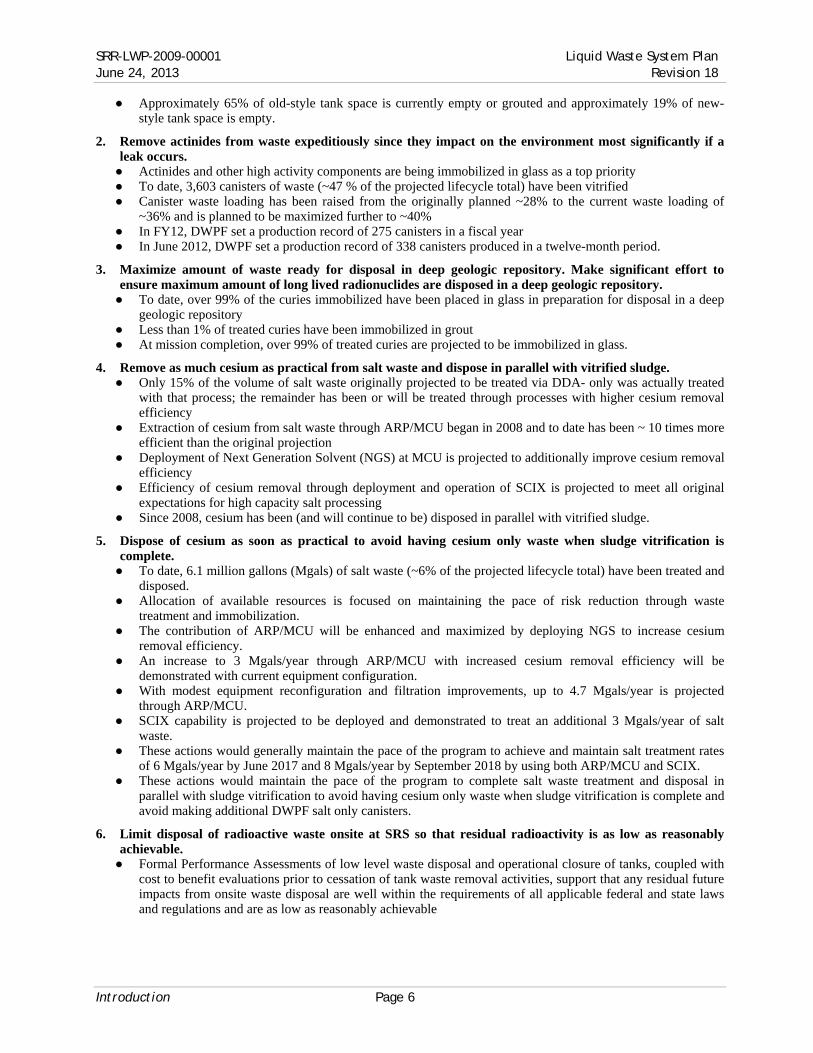
● Approximately 65% of old-style tank space is currently empty or grouted and approximately 19% of new-style tank space is empty.
2. Remove actinides from waste expeditiously since they impact on the environment most significantly if a leak occurs. ● Actinides and other high activity components are being immobilized in glass as a top priority ● To date, 3,603 canisters of waste (~47 % of the projected lifecycle total) have been vitrified ● Canister waste loading has been raised from the originally planned ~28% to the current waste loading of
~36% and is planned to be maximized further to ~40% ● In FY12, DWPF set a production record of 275 canisters in a fiscal year ● In June 2012, DWPF set a production record of 338 canisters produced in a twelve-month period.
3. Maximize amount of waste ready for disposal in deep geologic repository. Make significant effort to ensure maximum amount of long lived radionuclides are disposed in a deep geologic repository. ● To date, over 99% of the curies immobilized have been placed in glass in preparation for disposal in a deep
geologic repository ● Less than 1% of treated curies have been immobilized in grout ● At mission completion, over 99% of treated curies are projected to be immobilized in glass.
4. Remove as much cesium as practical from salt waste and dispose in parallel with vitrified sludge. ● Only 15% of the volume of salt waste originally projected to be treated via DDA- only was actually treated
with that process; the remainder has been or will be treated through processes with higher cesium removal efficiency
● Extraction of cesium from salt waste through ARP/MCU began in 2008 and to date has been ~ 10 times more efficient than the original projection
● Deployment of Next Generation Solvent (NGS) at MCU is projected to additionally improve cesium removal efficiency
● Efficiency of cesium removal through deployment and operation of SCIX is projected to meet all original expectations for high capacity salt processing
● Since 2008, cesium has been (and will continue to be) disposed in parallel with vitrified sludge.
5. Dispose of cesium as soon as practical to avoid having cesium only waste when sludge vitrification is complete. ● To date, 6.1 million gallons (Mgals) of salt waste (~6% of the projected lifecycle total) have been treated and
disposed. ● Allocation of available resources is focused on maintaining the pace of risk reduction through waste
treatment and immobilization. ● The contribution of ARP/MCU will be enhanced and maximized by deploying NGS to increase cesium
removal efficiency. ● An increase to 3 Mgals/year through ARP/MCU with increased cesium removal efficiency will be
demonstrated with current equipment configuration. ● With modest equipment reconfiguration and filtration improvements, up to 4.7 Mgals/year is projected
through ARP/MCU. ● SCIX capability is projected to be deployed and demonstrated to treat an additional 3 Mgals/year of salt
waste. ● These actions would generally maintain the pace of the program to achieve and maintain salt treatment rates
of 6 Mgals/year by June 2017 and 8 Mgals/year by September 2018 by using both ARP/MCU and SCIX. ● These actions would maintain the pace of the program to complete salt waste treatment and disposal in
parallel with sludge vitrification to avoid having cesium only waste when sludge vitrification is complete and avoid making additional DWPF salt only canisters.
6. Limit disposal of radioactive waste onsite at SRS so that residual radioactivity is as low as reasonably achievable. ● Formal Performance Assessments of low level waste disposal and operational closure of tanks, coupled with
cost to benefit evaluations prior to cessation of tank waste removal activities, support that any residual future impacts from onsite waste disposal are well within the requirements of all applicable federal and state laws and regulations and are as low as reasonably achievable

Liquid Waste System Plan SRR-LWP-2009-00001 Revision 18 June 24, 2013
Page 7 Introduction
● Based on operational experience, over 95% of the radioactive inventory in a tank has been removed after bulk waste removal and heel dilution; over 99% of the radioactive inventory has been removed after final cleaning
● At mission completion, over 99% of treated curies are projected to be immobilized in glass and packaged for offsite disposal in a deep geologic repository
● The originally agreed upon projection for onsite emplacement in engineered disposal units from liquid waste treatment and disposition was 3 MCi (2.5 MCi from DDA-only; 0.3 MCi from ARP/MCU; and 0.2 MCi from SWPF). Based on progress as of 2011, that projection for onsite emplacement was reduced to 0.8 MCi from 3 MCi
● The revised strategy to achieve salt waste treatment rates of 6 Mgals/year and 8 Mgals/year by June 2017 and September 2018, respectively, and to complete waste disposition by 2028 would maintain onsite emplacement in engineered disposal units within the reduced 0.8 MCi.
7. Ensure DOE’s strategy and plans are subject to public involvement and acceptance. ● The formal processes for evaluation, determination, and execution of all tank waste removal, disposal, and
operational closure fully involves SCDHEC, the Environmental Protection Agency (EPA), and the Nuclear Regulatory Commission (NRC)
● Various formal hold points exist in these processes for public involvement and comment ● All SRS Liquid Waste Disposition activities fall within the purview of DNFSB oversight, and DNFSB
periodically issues publically accessible reports of their evaluations and conducts periodic meetings to receive public input regarding their activities
● The SRS Citizen’s Advisory Board receives routine updates in a public venue regarding all SRS Liquid Waste Disposition activities
● Annual updates to this Plan are provided to all regulatory and oversight entities and made available for public review
● Quarterly updates of radiological inventory additions to SDUs are posted to a publically accessible website. ● SRR monthly and annual reports of progress towards disposition of SRS Liquid Waste are available to the
public
2.2 Goals
The overarching priorities for development of this Plan are: ● Continual Safe Storage of liquid waste in tanks and vitrified canisters in storage ● Maximize Risk Reduction through Waste Disposition ● Tank Cleaning and Grouting.
Development of Priorities for this Plan The overarching priorities are expressed through specific goals related to the various parts of the LW system. As documented in Revision 17 of this Plan, startup of SWPF by October 2014 was necessary to achieve compliance with all regulatory requirements. The delay of SWPF, however, adversely affects these regulatory commitments:
● Meet tank bulk waste removal efforts regulatory milestones in the currently-approved FFA ● Meet tank removal-from-service regulatory milestones in the currently-approved FFA ● Meet the waste treatment goals identified in the STP
In addition, projected funding for Revision 18 is insufficient to perform all activities needed for optimum performance of the Liquid Waste scope. Given the limited funding and the SWPF delay, prioritization criteria must be applied to guide allocation of the funding to the activities that provide the best value to DOE. For the purposes of this plan, two sets of prioritization criteria were evaluated:
Option A (Closure Acceleration Priority) ● Safe Storage ● Tank Cleaning & Grouting ● Hazard Elimination & Risk Reduction
Option B (Risk Reduction Priority) ● Safe Storage ● Hazard Elimination & Risk Reduction ● Tank Cleaning & Grouting

SRR-LWP-2009-00001 Liquid Waste System Plan June 24, 2013 Revision 18
Introduction Page 8
Option A places a preference on funding final cleaning and grouting of waste tanks to maximize compliance with near term regulatory requirements, while activities that improve waste processing rates (e.g., SCIX) receive limited funds. Option B gives preference to activities that maximize sludge and salt processing while cleaning and grouting activities (e.g., Tank 12 acid cleaning) are only funded if funds remain after salt and sludge acceleration activities are fully funded. In order to select the prioritization criteria to be used for the base case in this plan, modeling results based on the two prioritization techniques were examined and provide a comparison of achieving the FFA Bulk Waste Removal and Tank Closure Commitments. As depicted in Figure 2-1, the Closure Acceleration case provides a marginal improvement in BWR compliance by improving waste removal on tanks containing immobile dry salt at the expense of waste removal on tanks containing sludge that is both more mobile and more hazardous. The benefit of pursuing a closure acceleration path to near term tank closures is demonstrated in. Figure 2-2. It is worth noting that focusing on tank closure in the near term ultimately delays closure of the last old-style tank.
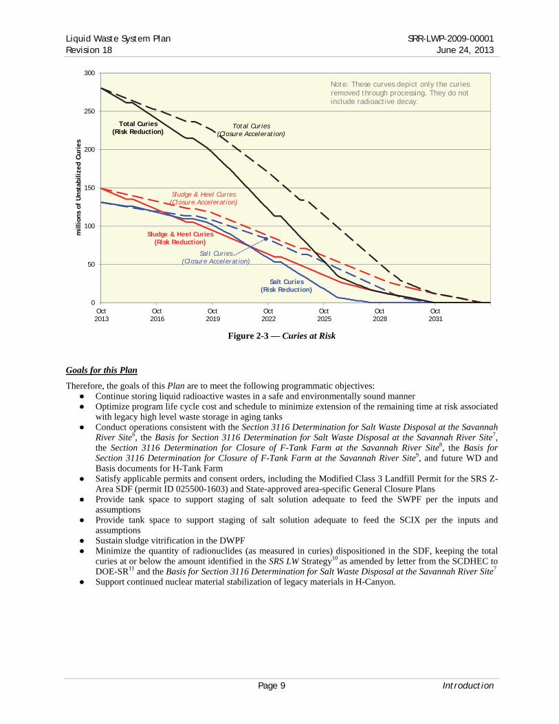
The consequence of focusing on near term closures is the significant increase in unstabilized curies remaining in the waste tanks. This undesirable result is clearly demonstrated in Figure 2-3. As a result of this examination, it is clear that the significant real benefit of maximized risk reduction far outweighs the limited perceived benefit of near term closures. In recognition of this determination, Option B (Risk Reduction Priority) has been chosen as the prioritization criteria for this plan.
Figure 2-1 — Bulk Waste Removals
Figure 2-2 — Tank Closures
FY23 FY24FY15 FY16 FY17 FY18 FY19 FY20 FY21 FY22
23H
1F
24H
10H
2F9H
21H
22H
14H
3F
13H
15H Sludge with higher leak potential
Tanks 4, 5, 6, 7, 8, 11, 12, 16, 17, 18, 19, and 20 —
Bulk Waste Removal Efforts Complete FFA Commitment
Option A – Risk Reduction
dry salt with essentially no leak potential
Option B – Closure Acceleration
FY13 FY14 FY15 FY16 FY17 FY18 FY19 FY20 FY21 FY22 FY23 FY24 FY25
FFA Commitment
Option B – Risk Reduction
FY26 FY27 FY28
21H9H
1F3F
10H
24H
2F
14H
4F
13H
23H
11H
8F
15H
22H
6F5F
7F
12H16H
Option A – Closure Acceleration
Liquid Waste System Plan SRR-LWP-2009-00001 Revision 18 June 24, 2013
Page 9 Introduction
Figure 2-3 — Curies at Risk
Goals for this Plan
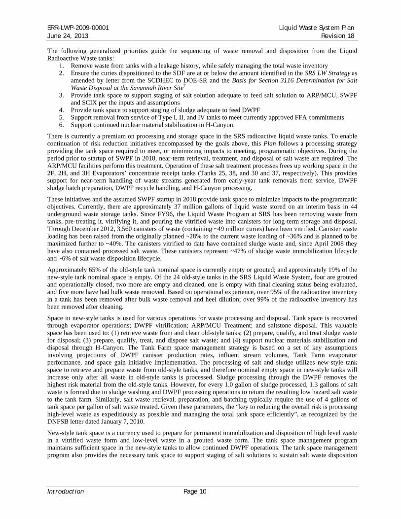
Therefore, the goals of this Plan are to meet the following programmatic objectives: ● Continue storing liquid radioactive wastes in a safe and environmentally sound manner ● Optimize program life cycle cost and schedule to minimize extension of the remaining time at risk associated
with legacy high level waste storage in aging tanks ● Conduct operations consistent with the Section 3116 Determination for Salt Waste Disposal at the Savannah
River Site6, the Basis for Section 3116 Determination for Salt Waste Disposal at the Savannah River Site7, the Section 3116 Determination for Closure of F-Tank Farm at the Savannah River Site8, the Basis for Section 3116 Determination for Closure of F-Tank Farm at the Savannah River Site9, and future WD and Basis documents for H-Tank Farm
● Satisfy applicable permits and consent orders, including the Modified Class 3 Landfill Permit for the SRS Z-Area SDF (permit ID 025500-1603) and State-approved area-specific General Closure Plans
● Provide tank space to support staging of salt solution adequate to feed the SWPF per the inputs and assumptions
● Provide tank space to support staging of salt solution adequate to feed the SCIX per the inputs and assumptions
● Sustain sludge vitrification in the DWPF ● Minimize the quantity of radionuclides (as measured in curies) dispositioned in the SDF, keeping the total
curies at or below the amount identified in the SRS LW Strategy10 as amended by letter from the SCDHEC to DOE-SR11 and the Basis for Section 3116 Determination for Salt Waste Disposal at the Savannah River Site7
● Support continued nuclear material stabilization of legacy materials in H-Canyon.
Sludge & Heel Curies (Closure Acceleration)
Salt Curies (Closure Acceleration)
Total Curies (Closure Acceleration)
Sludge & Heel Curies (Risk Reduction)
Salt Curies (Risk Reduction)
Total Curies (Risk Reduction)
0
50
100
150
200
250
300
Oct2013
Oct2016
Oct2019
Oct2022
Oct2025
Oct2028
Oct2031
million
s of
Unst
abiliz
ed C
uri
esNote: These curves depict only the curies removed through processing. They do not include radioactive decay.
SRR-LWP-2009-00001 Liquid Waste System Plan June 24, 2013 Revision 18
Introduction Page 10
The following generalized priorities guide the sequencing of waste removal and disposition from the Liquid Radioactive Waste tanks:
1. Remove waste from tanks with a leakage history, while safely managing the total waste inventory 2. Ensure the curies dispositioned to the SDF are at or below the amount identified in the SRS LW Strategy as
amended by letter from the SCDHEC to DOE-SR and the Basis for Section 3116 Determination for Salt Waste Disposal at the Savannah River Site7
3. Provide tank space to support staging of salt solution adequate to feed salt solution to ARP/MCU, SWPF and SCIX per the inputs and assumptions
4. Provide tank space to support staging of sludge adequate to feed DWPF 5. Support removal from service of Type I, II, and IV tanks to meet currently approved FFA commitments 6. Support continued nuclear material stabilization in H-Canyon.
There is currently a premium on processing and storage space in the SRS radioactive liquid waste tanks. To enable continuation of risk reduction initiatives encompassed by the goals above, this Plan follows a processing strategy providing the tank space required to meet, or minimizing impacts to meeting, programmatic objectives. During the period prior to startup of SWPF in 2018, near-term retrieval, treatment, and disposal of salt waste are required. The ARP/MCU facilities perform this treatment. Operation of these salt treatment processes frees up working space in the 2F, 2H, and 3H Evaporators’ concentrate receipt tanks (Tanks 25, 38, and 30 and 37, respectively). This provides support for near-term handling of waste streams generated from early-year tank removals from service, DWPF sludge batch preparation, DWPF recycle handling, and H-Canyon processing.
These initiatives and the assumed SWPF startup in 2018 provide tank space to minimize impacts to the programmatic objectives. Currently, there are approximately 37 million gallons of liquid waste stored on an interim basis in 44 underground waste storage tanks. Since FY96, the Liquid Waste Program at SRS has been removing waste from tanks, pre-treating it, vitrifying it, and pouring the vitrified waste into canisters for long-term storage and disposal. Through December 2012, 3,560 canisters of waste (containing ~49 million curies) have been vitrified. Canister waste loading has been raised from the originally planned ~28% to the current waste loading of ~36% and is planned to be maximized further to ~40%. The canisters vitrified to date have contained sludge waste and, since April 2008 they have also contained processed salt waste. These canisters represent ~47% of sludge waste immobilization lifecycle and ~6% of salt waste disposition lifecycle.
Approximately 65% of the old-style tank nominal space is currently empty or grouted; and approximately 19% of the new-style tank nominal space is empty. Of the 24 old-style tanks in the SRS Liquid Waste System, four are grouted and operationally closed, two more are empty and cleaned, one is empty with final cleaning status being evaluated, and five more have had bulk waste removed. Based on operational experience, over 95% of the radioactive inventory in a tank has been removed after bulk waste removal and heel dilution; over 99% of the radioactive inventory has been removed after cleaning.
Space in new-style tanks is used for various operations for waste processing and disposal. Tank space is recovered through evaporator operations; DWPF vitrification; ARP/MCU Treatment; and saltstone disposal. This valuable space has been used to: (1) retrieve waste from and clean old-style tanks; (2) prepare, qualify, and treat sludge waste for disposal; (3) prepare, qualify, treat, and dispose salt waste; and (4) support nuclear materials stabilization and disposal through H-Canyon. The Tank Farm space management strategy is based on a set of key assumptions involving projections of DWPF canister production rates, influent stream volumes, Tank Farm evaporator performance, and space gain initiative implementation. The processing of salt and sludge utilizes new-style tank space to retrieve and prepare waste from old-style tanks, and therefore nominal empty space in new-style tanks will increase only after all waste in old-style tanks is processed. Sludge processing through the DWPF removes the highest risk material from the old-style tanks. However, for every 1.0 gallon of sludge processed, 1.3 gallons of salt waste is formed due to sludge washing and DWPF processing operations to return the resulting low hazard salt waste to the tank farm. Similarly, salt waste retrieval, preparation, and batching typically require the use of 4 gallons of tank space per gallon of salt waste treated. Given these parameters, the “key to reducing the overall risk is processing high-level waste as expeditiously as possible and managing the total tank space efficiently”, as recognized by the DNFSB letter dated January 7, 2010.
New-style tank space is a currency used to prepare for permanent immobilization and disposition of high level waste in a vitrified waste form and low-level waste in a grouted waste form. The tank space management program maintains sufficient space in the new-style tanks to allow continued DWPF operations. The tank space management program also provides the necessary tank space to support staging of salt solutions to sustain salt waste disposition

Liquid Waste System Plan SRR-LWP-2009-00001 Revision 18 June 24, 2013
Page 11 Introduction
currently through ARP/MCU and subsequently through SWPF and SCIX. Of the 27 new-style tanks (with a total nominal volume of 35.1 million gallons) in the SRS Liquid Waste System:
● 5 are dedicated to salt batching, qualification, and disposition (including DWPF recycle beneficial reuse and the 2H Evaporator)
● 6 are dedicated to sludge batching, qualification, and disposition (including the 3H Evaporator) ● 3 are dedicated to waste retrieval from and residual cleaning of old-style tanks in preparation for operational
closure ● 1 is dedicated to uninterrupted H-Canyon waste receipts ● 12 are dedicated to safe storage of legacy liquid waste pending retrieval and disposition.
There are currently ~6.8 Mgals of empty space (~19%) in these new-style tanks: ● 3.0 Mgals is margin as defense-in-depth operational control coupled with Safety Class or Safety Significant
(SC/SS) systems, structures and components (SSC) to facilitate reasonably conservative assurance of more than adequate dilution and ventilation of potentially flammable vapors
● 1.3 Mgals is procedurally-required minimum contingency space for recovery from the unlikely event of a bulk waste leak elsewhere in the system
● 2.5 Mgals is operational “working” space variously used to provide: — Additional contingency transfer space as operational excess margin above the procedurally-required
minimum — Excess margin to preserve salt batch quality and maintain uninterrupted treatment and disposition
through ARP/MCU and Saltstone — Excess margin to preserve sludge batch quality and maintain uninterrupted immobilization through
DWPF ● Excess margin to preserve uninterrupted support for H-Canyon.
2.3 Alternative Analyses
This Plan provides a modeled analysis to describe the potential impacts of further delaying initiation of SWPF operations to September 30, 2023 from October 2018.
2.4 Risk Assessment
The PBS-SR-0014, Radioactive Liquid Tank Waste Stabilization and Disposition, Risk and Opportunity Management Plan12 (ROMP) documents the comprehensive identification and analysis of technical risks and opportunities associated with the LW program. It identifies individual technical and programmatic risks and presents the strategies for handling risks and opportunities in the near-term and outyears.

SRR-LWP-2009-00001 Liquid Waste System Plan June 24, 2013 Revision 18
Planning Bases Page 12
3. Planning Bases
This Plan is based on inputs and assumptions provided by DOE. Dates, volumes, and chemical or radiological composition information contained in this Plan are planning approximations only. Specific flowsheets guide actual execution of individual processing steps. The activities described are summary-level activities, some of which have yet to be fully defined. The sequence of activities reflects the best judgment of the planners. The individual activity execution strategies contain full scope, schedule, and funding development. Upon approval of scope, cost, and schedule baselines modifications of this Plan may be required.
3.1 Funding
Progress toward the ultimate goal of immobilizing all the LW at SRS is highly dependent on available funding. This Plan was developed assuming the availability of the funding required as specified in DE-AC09-09SR22505: Revision 3- Savannah River Remediation. (SRR) Office of Environmental Management (EM) Preliminary) FY 2013 Expected Funds 13. It supports justification for requesting necessary funding profiles. With any reduction from full funding, activities that ensure safe storage of waste claim first priority. Funding above that required for safe storage enables risk reduction activities, i.e., waste removal, treatment — including immobilization — and removal from service, as described in this Plan.
3.2 Regulatory Drivers
Numerous laws, constraints, and commitments influence LW System planning. Described below are requirements most directly affecting LW system planning. This Plan assumes the timely acquisition of regulatory approvals.
South Carolina Environmental Laws
Under the South Carolina Pollution Control Act, S.C. Code Ann. §§ 48-1-10 et seq., SCDHEC is the delegated authority for air pollution control and water pollution control. The State has empowered SCDHEC to adopt standards for protection of water and air quality, and to issue permits for pollutant discharges. Further, SCDHEC is authorized to administer both the federal Clean Water Act and the Clean Air Act. Under South Carolina’s Hazardous Waste Management Act, S.C. Code Ann. §§ 44-56-10 et seq., SCDHEC is granted the authority to manage hazardous wastes. With minor modifications, SCDHEC has promulgated the federal Resource Conservation and Recovery Act (RCRA) requirements, including essentially the same numbering system. The South Carolina Solid Waste Policy and Management Act, S.C. Code Ann. §§ 44-96-10 et seq., provides standards for the management of most solid wastes in the state. For example, SCDHEC issued to DOE-SR permits such as the Class 3 Landfill Permit for SDF. This landfill permit contains conditions for the acceptable disposal of non-hazardous waste in the SDF. This permit also contains provisions for fines and penalties. Other principal permits required to operate LW facilities pursuant to the state’s environmental laws include:
● SCDHEC Bureau of Water: — Industrial wastewater treatment facility permits (e.g., Tank Farms, DWPF, ARP/MCU, Effluent
Treatment Facility [ETF], and the SPF) — National Pollutant Discharge Elimination System (NPDES) permit (H-16 Outfall discharges from ETF)
● SCDHEC Bureau of Air Quality: — Part 70 Air Quality Permit (one Site-wide Air Permit including the LW facilities).
Site Treatment Plan (STP)
The STP5 for SRS describes the development of treatment capacities and technologies for mixed wastes, and provides guidance on establishing treatment technologies for newly identified mixed wastes. The STP allows DOE, regulatory agencies, the States, and other stakeholders to efficiently plan mixed waste treatment and disposal by considering waste volumes and treatment capacities on a national scale. The STP identifies vitrification in DWPF as the preferred treatment option for appropriate SRS liquid high-level radioactive waste streams. SRS has committed that:
“Upon the beginning of full operations, DWPF will maintain canister production sufficient to meet the commitment for the removal of the backlogged and currently generated waste inventory by 2028.”
The commitment for the removal of the waste by 2028 encompasses the BWRE and heel removal scope of this Plan. Final cleaning, deactivation, and removal from service of storage and processing facilities are subsequent to the satisfaction of this commitment.

Liquid Waste System Plan SRR-LWP-2009-00001 Revision 18 June 24, 2013
Page 13 Planning Bases
Federal Facility Agreement (FFA)
The EPA, DOE, and SCDHEC executed the SRS FFA4 on January 15, 1993, which became effective August 16, 1993. It provides standards for secondary containment, requirements for responding to leaks, and provisions for the removal from service of leaking or unsuitable LW storage tanks. Tanks scheduled to be removed from service may continue to be used, but must adhere to the FFA schedule for removal from service and the applicable requirements contained in the Tank Farms’ industrial wastewater treatment facility permit. An agreement between DOE, SCDHEC, and EPA (Statement of Resolution of Dispute Concerning Extension of Closure Dates for Savannah River Site High-Level Radioactive Waste Tanks 19 and 1814 effective in November 2007) modified the FFA by providing for the submission of Waste Determination documentation for F- and H-Tank Farms and including end dates for BWRE and the operational closure of each old style tank. The FFA requires SRS to operationally close the last Type I, II, and IV tank no later than 2022.
National Environmental Policy Act
The National Environmental Policy Act (NEPA) requires federal agencies to assess the potential environmental impacts of proposed actions. Seven existing NEPA documents and their associated records of decision directly affect the LW System and support the operating scenario described in this Plan:
● DWPF Supplemental Environmental Impact Statement (SEIS) (DOE/EIS-0082-S) ● Final Waste Management Programmatic Environmental Impact Statement (PEIS) (DOE/EIS-0200-F) ● SRS Waste Management Final Environmental Impact Statement (EIS) (DOE/EIS-0217) ● Interim Management of Nuclear Materials EIS (DOE/EIS-0220) ● SRS High-Level Waste Tank Closure Final EIS (DOE/EIS-0303) ● Environmental Assessment (EA) for the Closure of the High Level Waste Tanks in F- and H Areas at SRS
(DOE/EA-1164) ● SRS Salt Processing Alternatives Final SEIS (DOE/EIS-0082-S2).
Ronald W. Reagan National Defense Authorization Act for Fiscal Year 2005
The Ronald W. Reagan National Defense Authorization Act for Fiscal Year 2005 (NDAA) Section 3116 (NDAA §3116) allows determinations by the Secretary of Energy, in consultation with the NRC, that certain radioactive waste from reprocessing is not high-level waste and may be disposed of in South Carolina pursuant to a State-approved closure plan or State-issued permit. For salt waste, DOE contemplates removing targeted fission products and actinides using a variety of technologies and combining the removed fission products and actinides with the metals being vitrified in DWPF. NDAA §3116 governs solidifying the remaining low-activity salt stream into saltstone for the purpose of disposal in the SDF. For Type I, II, and IV tank removal from service activities, NDAA §3116 governs the Waste Determinations for the Tank Farms that demonstrate that the tanks and ancillary equipment (evaporators, diversion boxes, etc.) at the time of removal from service and stabilization can be managed as non-high level waste.
3.3 Revisions
The significant updates from the previous version of this Plan, the Liquid Waste System Plan, Revision 172, include: ● Salt Processing:
— SWPF Processing: SWPF operations initiation delayed to October 2018 from October 2014 — SWPF Processing: SWPF maximum processing rate increased to 9 Mgal/yr from 8 Mgal/yr — SCIX Processing: reschedule of SRR’s proposal of a supplemental salt treatment process to April 2019
from October 2018 due to funding limitations — SCIX Processing: SCIX maximum processing rate increased to 3 Mgal/yr from 2.5 Mgal/yr — Next Generation Extractant: Next generation extractant is deployed at MCU
● Sludge Processing — Reduced the maximum canister throughput to 275 canisters per year from 315 canister per year
● Tank Closure — Increased durations for near-term regulatory approvals
SRR-LWP-2009-00001 Liquid Waste System Plan June 24, 2013 Revision 18
Planning Bases Page 14
— Eliminate implementation of ECC due to funding — Delays in tank removal from service that are beyond FFA commitments for BWRE and operational
closure commitments
3.4 Key Milestones
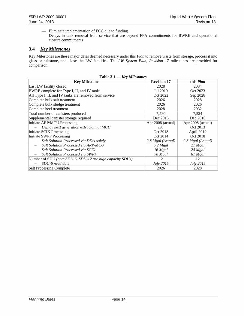
Key Milestones are those major dates deemed necessary under this Plan to remove waste from storage, process it into glass or saltstone, and close the LW facilities. The LW System Plan, Revision 17 milestones are provided for comparison.
Table 3-1 — Key Milestones
Key Milestone Revision 17 this Plan Last LW facility closed 2028 2034 BWRE complete for Type I, II, and IV tanks Jul 2019 Oct 2023 All Type I, II, and IV tanks are removed from service Oct 2022 Sep 2028 Complete bulk salt treatment 2026 2028 Complete bulk sludge treatment 2026 2026 Complete heel treatment 2028 2032 Total number of canisters produced 7,580 7,824 Supplemental canister storage required Dec 2016 Dec 2016 Initiate ARP/MCU Processing Apr 2008 (actual) Apr 2008 (actual)
– Deploy next generation extractant at MCU n/a Oct 2013 Initiate SCIX Processing Oct 2018 April 2019 Initiate SWPF Processing Oct 2014 Oct 2018
– Salt Solution Processed via DDA-solely 2.8 Mgal (Actual) 2.8 Mgal (Actual) – Salt Solution Processed via ARP/MCU 5.2 Mgal 21 Mgal – Salt Solution Processed via SCIX 16 Mgal 24 Mgal – Salt Solution Processed via SWPF 78 Mgal 61 Mgal
Number of SDU (note SDU-6–SDU-12 are high capacity SDUs) 12 12 – SDU-6 need date July 2015 July 2015
Salt Processing Complete 2026 2028

Liquid Waste System Plan SRR-LWP-2009-00001 Revision 18 June 24, 2013
Page 15 Planning Summary and Results
4. Planning Summary and Results
This section summarizes the key attributes of this Plan. Detailed discussion on risks and associated mitigation strategies are included in other documents such as the ROMP and individual implementation activity risk assessments.
In addition, this Plan assumes receiving adequate funding to achieve the required project and operations activities. Failure to obtain adequate funding will have a commensurate impact on the programmatic objectives.
This section summarizes the Plan, based on the key assumptions and bases. Tabular results of the lifecycle, on a year-by-year basis, or graphical results of the lifecycle are included in:
● Appendix A — Salt Solution Processing ● Appendix B — Sludge Processing ● Appendix C — Canister Storage ● Appendix D — BWRE & Removal from Service ● Appendix E — Tank Farm Influents and Effluents ● Appendix F — Remaining Tank Inventory ● Appendix G — LW System Plan — Rev 18 Summary
4.1 Disposition of Sludge Waste
The basic steps for sludge processing (Figure 4-1) are: 1. Sludge removal from tanks 2. Blending and washing of sludge (in Tank 51) 3. Sludge feeding to the DWPF (from Tank 40) 4. Vitrification in DWPF.
Sludge processing
Sludge processing is paced by the capabilities of the sludge washing and the DWPF processing facilities and by tank storage space to prepare sludge batches. Sludge batch planning uses the estimated mass and composition of sludge and known processing capabilities to optimize processing sequences. Sub-tier plans document the modeling, guide the sequence of waste removal, and support a more detailed level of planning. These sub-tier plans are revised as new information becomes available or when significant updates in the overall waste removal strategy are made. The specific input to this Plan from sludge batch planning is summarized in Sludge Batch Plan in Support of System Plan Rev. 1815.
Differences in sludge batch sequencing, total number canisters produced, and batch end dates between Sludge Batch Plan in Support of System Plan Rev. 18 and Sludge Batch Plan in Support of System Plan Rev. 1716 are mainly driven by the following:
● This Plan assumes the use of LTAD for Sludge Batch (SB) 12 through 16. — Most of Tank 13 is no longer targeted for LTAD — The majority of Tank 15 sludge is no longer targeted for LTAD
because there is no viable disposition option for the aluminum rich supernate
● This Plan assumes 21 total sludge batches — Batches 18–21 are primarily sludge heels, insoluble salt, and
oxalates ● The projected canister pour rate and waste loadings remain at 275
canisters/yr; no second sludge preparation tank is anticipated ● In addition to SB7, three other sludge batches are modeled to
include enough washing to remove sodium oxalate solids that originate from bulk Oxalic Acid (OA) chemical cleaning operations
Figure 4-1 — Sludge Feed Preparation

SRR-LWP-2009-00001 Liquid Waste System Plan June 24, 2013 Revision 18
Planning Summary and Results Page 16
Sludge Feed Preparation
This Plan uses a single sludge tank (Tank 51) as the sole DWPF feed preparation tank (see Figure 4-1).
Sludge Washing
Sodium and other soluble salts in DWPF feed are reduced through sludge washing. Sludge washing is performed by adding water to the sludge batch, mixing with slurry pumps, securing the pumps to allow gravity settling of washed solids, and decanting the sodium-rich supernate to an evaporator system for concentration. This cycle is repeated until the desired sodium molarity, typically 1.5 M Na, is reached. Some types of sludge settle slowly, extending wash cycles. Sludge settling and washing typically constitutes ~75% of batch preparation time. The total number of washes performed and volume of wash water used are minimized to conserve waste tank space. Sludge batch size and wash volumes are also limited by the hydrogen generation rate associated with radiolysis of water. Tank contents are mixed on a periodic frequency to release hydrogen retained within the sludge layer, resulting in a limited window within operating constraints for gravity settling.
4.2 DWPF Operations
Washed sludge is transferred to the DWPF facility where it is combined with the high-level waste streams from salt processing (discussed below) for vitrification into glass canisters and stored on-site pending disposition.
Historically, melter performance has been the limiting factor for DWPF throughput. The DWPF melter (without bubblers) had produced an average of 215 canisters/yr before melter bubblers were installed. Bubblers installed in September 2010, however, improved the demonstrated melter capacity to a rate of 37 canisters/month (444 canisters/year), resulting in a record 264 canisters poured in FY11 and 277 in FY12. Tank Farm sludge waste feed preparation has been analyzed to be capable of supporting a canister production capability of 275 canisters/year while DWPF feed preparation systems have demonstrated a capacity of greater than 325 canisters/year, e.g., the 337 canisters poured from July 2011 thru June 2012.
Sludge Batch 7B processing challenges were encountered towards the end of FY12 and continued to be experienced during the first part of FY13. The primary challenge was associated with sludge carryover into the vessel vent and recycle collection systems. Mitigation efforts were focused in the following areas:
● Compliance with Technical Safety Requirement (TSR) Specific Administrative Controls (SAC) — The time consuming laboratory analytical method to determine solids content of recycle material was
replaced by implementing a turbidity instrument for solids carryover detection. This effort reduced cycle time by 20 hours per batch
— A Documented Safety Analysis (DSA) change package was developed that maintains the recycle system under caustic and nitrite inhibited conditions, which will provide additional operational flexibility and improve cycle times
— Digital Control System (DCS) Software was developed and loaded to increase the ability to detect sludge carryover events. Work continues on development of automated DCS software to both detect the onset and provide control action to prevent sludge carryover events
— Process vessel air purge system modifications are scheduled for later this year. ● Chemical Process Cell Processing with Certainty
— An independent team of local (i.e. Savannah River National Laboratory (SRNL) & SRR) experts was assembled to review past processing data. The team of experts provided recommendations for both batch processing and carryover prevention
— DWPF completed a 14 day outage to flush and clean the Process Vessel Vent system in order to restore proper flows to this system following system degradation caused by sludge carryover.
Near-term improvements are complete and historical canister productions rates have once again been demonstrated. As part of the longer-term comprehensive effort, an Independent Peer Review of recent DWPF operating performance was conducted, including feed preparation and controls, feed chemistry, melter performance, support system performance and reliability, and melter flammability controls. The overall objective is to assure we have fully identified, evaluated, and developed actions to fully address the core issues that could prevent DWPF from meeting its aggressive production commitments. A DWPF reliability improvement and maintenance plan was developed incorporating the team’s input.

Liquid Waste System Plan SRR-LWP-2009-00001 Revision 18 June 24, 2013
Page 17 Planning Summary and Results
Two-step Production Improvement Approach
To support higher glass throughput, the DWPF melter was retrofitted with four bubbler systems and the melter off-gas system was optimized in September 2010. The second step of DWPF production capacity improvement program addresses streamlining the DWPF feed preparation system. Several process improvements are planned to streamline the DWPF feed preparation system:
● Implementation of an alternate reductant ● Processing of cesium strip effluent in the slurry mix evaporator (SME) ● Addition of dry process frit to the SME
The feed preparation modifications reduce recycle water generation by 660 kgal/yr: ● 250 kgal/yr by using dry process frit ● 1.5 kgal/canister × 275 canisters/yr = 410 kgal/yr by routing decon frit water to ETF.
Reduction of liquid addition in DWPF supports receipt of Strip Effluent (SE) from SWPF. Beneficial reuse of DWPF recycle for waste removal and tank cleaning, in lieu of water additions, supplements recycle reduction and supports maintenance of tank farm capacity (see §4.6 below).
The DWPF production rate (prior to the bubbler installation) averaged 215 canisters per year with ~4,000 pounds of glass per canister. The production rate improvement initiatives enable a higher nominal DWPF canister production capability of 275 canisters/year. Future estimated canister production, by year is shown in Table 4-1 — Planned DWPF Production Rates. The canister rates assume two one-week outages every year to allow for routine planned maintenance and another two week site-wide steam outage each year.
Table 4-1 — Planned DWPF Production Rates
FY Nominal Rate Outage Total DWPF
Canisters poured (Canisters/yr) (Months) (Canisters)
FY13 275 275 FY14 275 276 FY15 275 4 184 FY16 275 276 FY17 275 276 FY18 275 4 184 FY19 275 276 FY20 275 276 FY21 275 276 FY22 275 276 FY23 275 4 184 FY24 275 276 FY25 275 276 FY26 275 276 FY27 275 169 FY28 (sludge heels) 153 FY29 (sludge heels) 132 FY30 (sludge heels) 122 FY31 (sludge heels) 133
a Four-month melter outage is assumed every eight years during sludge processing. Actual melter change-out is determined by melter performance
b Four-Month outage in 2018 to accommodate transition to SWPF-DWPF coupled operations — assumes no canister production rate impact from coupled SWPF-DWPF operations
c Lower production rate assumed for dilute heel processing beginning in 2028.
Failed Equipment Storage Vaults and Melter Storage Boxes
Failed equipment storage vaults (FESVs) and Melter Storage Boxes (MSBs) are repetitive activities required to sustain ongoing DWPF operation by providing interim storage of failed DWPF melters. The original DWPF design

SRR-LWP-2009-00001 Liquid Waste System Plan June 24, 2013 Revision 18
Planning Summary and Results Page 18
has two vaults contained within one construction unit. Each FESV is designed to store one failed melter inside an MSB.
Melter 1 was placed in FESV #2 in December 2002. Melter 1 (inside MSB #1) had a relatively low radiation field. It was placed in the northernmost vault since the next vault pair to be constructed would be adjacent to FESV #2.
FESV #1 remains available for use with Melter 2. Construction of MSB #2 was completed in October 2008. MSB #2 is currently stored in FESV #1 awaiting use during the Melter 2 replacement outage currently forecast in this Plan to occur in 2015. Space has been reserved for construction of up to ten FESVs, if needed.
Under the current planning basis, the need date for FESV #3 and #4 will be triggered by the failure of Melter 3. Melter 3 is currently scheduled to be placed into service in July 2015. Based upon this strategy, FESVs #3 and #4 construction should be completed and available for service by January 2015 (approximately six months prior to the planned installation of Melter 3). Likewise, MSB #3 should be constructed and available to receive Melter 3 by January 2015. The need dates for FESV #3 and #4 and successive pairs of vaults will be evaluated on an ongoing basis.
Currently, the FESV 200-ton gantry crane is designed to interface only with an MSB designed primarily to contain failed melters. The placement of other large failed DWPF equipment (which do not have disposal paths) in FESVs has been considered but the complete engineered system to move large contaminated equipment from the 221-S canyon to the FESV has not been designed or constructed. Alternative methods for disposal of large contaminated equipment from DWPF (not including melters) are being evaluated.
Glass Waste Canister Storage
The canisters of vitrified HLW glass produced by DWPF are currently stored on-site in dedicated interim storage buildings, Glass Waste Storage Buildings (GWSB). A Shielded Canister Transporter moves one canister at a time from the Vitrification Building to a GWSB. The schedule for filling the GWSBs is found in Appendix C — Canister Storage.
GWSB #1 consists of a below-grade seismically qualified concrete vault containing support frames for vertical storage of 2,262 standard canisters. Eight of these positions have been abandoned due to construction defects and three contain archived non-radioactive glass filled canisters. As of December 31, 2012, 2,244 standard positions are in use storing radioactive canisters, the remaining 7 being contingency positions for placement of canisters if GWSB #2 is temporarily unavailable.
GWSB #2, with a similar design to GWSB #1, has 2,340 standard storage locations. The first radioactive canister was placed in GWSB #2 on July 10, 2006. One archived non-radioactive canister has been placed in GWSB #2. As of December 31, 2012, GWSB #2 stored 1,302 canisters. The total storage capacity of GWSB #1 and #2 for standard radioactive storage is 4,590.
The current GWSBs are forecast to be full by the end of 2016. Supplemental glass waste storage must be ready to store canisters in FY17 in order to maintain production of DWPF canisters. Scoping studies are being conducted to determine the configuration of the supplemental storage. Funding limitations have delayed the start of design and construction of this needed supplemental glass waste storage such that, at present, it is unlikely that supplemental storage will be available by the FY17 need date.
The schedule for shipment of the canisters from SRS is not included in this Plan and is unknown at this time.
4.3 Disposition of Salt Wastes
As highlighted in the Introduction, this Plan includes the use of a series of salt treatment processes over the life of the program, including ARP/MCU, SCIX, and SWPF. Appendix A — Salt Solution Processing reflects the breakdown of the volumes treated from each of the processes by year. Using the input assumptions for this Plan, over 100 Mgal of salt solution from the Tank Farms are planned for processing over the life of the program; 5.6 Mgal was processed by the end of FY12. If SWPF starts up in October 2018 as assumed, it would processes the majority of this salt solution waste. The nominal capacity of SWPF, after an initial 36-month start-up period is assumed to be approximately 9 Mgal/yr. Coupled with the SCIX throughput of ~3 Mgal/yr, 12 Mgal/yr is the total planned nominal salt processing capacity. It must be noted that salt processing may be limited by SE processing in DWPF at the planned rates. At a DWPF production rate of 275 canisters/year, achieving greater than 7 Mgal/yr of SWPF processing will require reducing the strip effluent volume. The specific input to this Plan from salt batch planning is summarized in Salt Batch Plan in Support of System Plan R 1817.

Liquid Waste System Plan SRR-LWP-2009-00001 Revision 18 June 24, 2013
Page 19 Planning Summary and Results
4.3.1 Actinide Removal Process / Modular CSSX Unit (APR/MCU)
Salt waste is currently processed through ARP/MCU. A summary of the process is shown in Figure 4-2 — Schematic of the ARP/MCU Process. Table 4-2 — ARP/MCU Salt Batch Composition gives the composition of the salt batches for ARP/MCU.
The ARP decontaminates salt solution via adsorption of strontium-90 (Sr-90), actinide radionuclides, and entrained sludge solids in the salt solution onto mono-sodium titanate (MST) followed by filtration. The actinide, Sr-90, and MST laden sludge waste stream are transferred to DWPF for vitrification and the remaining clarified salt solution is transferred to the MCU process. The MCU process extracts Cs from the clarified salt solution using CSSX chemistry. The low Cs-137/low actinide decontaminated salt solution (DSS) is subsequently transferred to Tank 50 for feed to the SPF, and the SE solution of cesium nitrate from the CSSX process is transferred to the DWPF for vitrification.
The ARP/MCU process was constructed and permitted initially for a three-year service period, bridging the crucial period before the startup of the SWPF. With the delay of SWPF, however, ARP/MCU has been enhanced and improved to provide a longer term option for salt disposition (see Life-Extension discussion below). The original goals of the ARP/MCU process were to (1) treat salt solution prior to the start of SWPF; and importantly (2) provide operational experience and lessons learned for the SWPF project.
Actions taken since startup of ARP/MCU have demonstrated an increased processing rate from the original design of 1 million gallons per year to approximately 1.4 million gallons per year. Enhancements and improvements include chemistry adjustments at Tank 49, modified MST, reduced cycle-times, redesign and replacement of the secondary filter at 512-S. A twelve-hour strike time was implemented at ARP, along with a 6-gpm processing rate increase at MCU which reduced the overall processing cycle-time.
Although the overall attainment has significantly improved through operations, equipment downtime has limited the overall attainment hence overall throughput. The majority of the affected equipment has been repaired, replaced, or redesigned commensurate with the failure causes identified. Efforts continue to improve equipment reliability, reducing unexpected downtime to improve overall attainment. In addition to equipment and processing upgrades, alternative system planning is being done to more efficiently qualify subsequent salt batches to reduce downtime between batches.
Life-Extension
The originally planned three-year service life of ARP/MCU was reached in 2012. A detailed engineering analysis (ARP/MCU Life Extension Evaluation18) identified the key parameters necessary for life extension. Most of the individual components were determined to be capable of a longer operating life than three years. An evaluation
Figure 4-2 — Schematic of the ARP/MCU Process

SRR-LWP-2009-00001 Liquid Waste System Plan June 24, 2013 Revision 18
Planning Summary and Results Page 20
concluded that ARP/MCU can operate until 2015 before major equipment failure is expected. The passive process components, such as piping and structures, were determined to have service life beyond 2025.
The life of ARP/MCU has been extended through: ● Process and equipment upgrades and improvements ● Evaluation and procurement of spare parts ● Adjustment to preventive maintenance ● Increased equipment performance monitoring ● Appropriate regulatory approvals
Active components by their nature are consumable and degrade in performance over time. Active components would include, for example, motors, pump rotating assemblies and seals, actuators, operators, hand switches, instruments, indicators, and gauges. Passive components are not considered consumable, however over time they will degrade. Passive components include, for example, cell coatings, building structures, tanks and vessels, piping, pump casings, and valve bodies. While the original service life basis for ARP/MCU has been validated, extending the life of ARP/MCU required that some process equipment be replaced due to radiological or chemical failure. To successfully operate ARP/MCU for longer than the original service life of three years (2012), equipment at high risk of failure will be monitored to give early warning of impending failure, i.e. motors and equipment in high radiation areas.
Enhanced Throughput
The detailed engineering analysis of the ARP/MCU flowsheet identified the key rate-limiting steps in the ARP/MCU process, and opportunities to maximize rates of processing through these steps. The ARP/MCU process essentially consists of salt feed for adsorption of actinides, followed by filtration of solids, and solvent exchange to capture cesium. The adsorption is accomplished via addition of MST ion exchange resin to a strike tank along with salt waste. Following the ion exchange process, the salt solution is transferred to a cross-flow filtration facility, where salt solution is passed through a 0.1 micron sintered metal cross-flow filter. The MST solids are gradually concentrated over the course of multiple microbatches and transferred to DWPF after washing to remove excess sodium. The filtrate stream is sent to MCU for removal of soluble Cs-137. Following a cross-flow filter chemical cleaning effort, the heels of the filter tanks are chemically adjusted and the next cycle of waste receipt and filtration resumes. The filtrate stream is sent to MCU for removal of soluble Cs-137.
The facilities which comprise the ARP were able to provide consistent feed to the MCU throughout the first three Salt Batches. During this time, MCU was capable of operating at a feed rate of 4–6 gpm. Following the transition to Salt Batch 4, MCU Operations successfully demonstrated the ability to process at a sustained rate of 8.5 gpm. As such, it was concluded that throughput is limited by the cross-flow filtration processing rate. A System Engineering Evaluation on the ARP filtration system, as well as an Integrated Salt Processing flow sheet evaluation will be performed. An enhanced throughput strategy will be developed to eliminate discrepancies and provide the basis to maintain a 3 Mgal/year processing rate. Additionally in parallel, the following near-term enhancements are planned:
● Perform an Integrated salt processing flow sheet evaluation ● Change the cross-flow filter operation from batch-operation to continuous operation ● Reduce the amount of MST added at the ARP facility and evaluate reduced strike time ● Increase the temperature limit specified to allow for enhanced filtration ● Adjust the secondary filter cleaning strategy ● Adjust the current back-pulse and cross-flow filter loading strategies. ● Increase the Trans-membrane pressure ● Optimize the operating strategy and time to end of cycle ● Optimize filtration scouring strategies to maximize filtrate flow rate.
A plan to demonstrate the increased throughput including a phased approach to implementation, monitoring parameters, and criteria for measurement and achievement is being developed.
Improved Decontamination
In the fourth quarter of FY2013, the original solvent formula will be replaced with a next generation solvent (NGS). Operation of ARP/MCU with NGS will result in two benefits. First, this solvent is more efficient at removing cesium from the treated salt solution than the original solvent formula. This increased cesium removal efficiency (decontamination factor or DF) is expected to enable ARP/MCU to produce a DSS stream with a residual cesium concentration orders of magnitude less than achieved currently. The improved DF will enable continued operation of ARP/MCU while minimizing the curies disposed in the SDF. Second, NGS will enable a future increase of MCU

Liquid Waste System Plan SRR-LWP-2009-00001 Revision 18 June 24, 2013
Page 21 Planning Summary and Results
throughput to 12 gpm. Following the initial deployment of NGS in 2013, ARP/MCU will continue to be operated at 8.5 gpm until mid-2015. During this period, operational data will be obtained that will support adjustments within MCU that may be needed to sustain 12 gpm production at MCU.
Enhanced Throughput (phase II)
After sufficient operational data is obtained and in conjunction with the planned outage for contactor bearing replacements in 2015, the throughput of ARP/MCU will be increased to approximately 12 gpm enabling a nominal ARP/MCU production of 4.7 Mgal/yr. While the deployment of NGS will enable the increase in MCU throughput, a revised filtration strategy will be employed to accelerate ARP. To support an increased rate of actinide removal, addition of MST will occur in a waste tank prior to transfer of the salt solution Tank 49. This process is known as “large-tank strike” and is essentially moving ARP upstream of Tank 49. The large-tank strike, settle/decant then filter will remove the ARP process as a throughput constraint. Whereas the current process (Tank 49 → ARP 96H → ARP 512-S→MCU) has close coupled operation of ARP and MCU, the new configuration (ARP → Tank 49/filtration → MCU) places a large supply of Clarified Salt Solution feed directly in front of MCU improving overall system attainment.
Table 4-2 — ARP/MCU Salt Batch Composition
Batch Source Tanks
Nominal Volume (kgal)
ARP/MCU B7 Tank 23 liquid (Tank 41 salt dissolution (SD)); Tank 11 liquid (Tank 10 SD); Tank 38 liquid (2H liquor).
1,000
ARP/MCU B8 Tank 23 liquid (Tank 41 SD and Tank 35 supernate); Tank 35 supernate; Tank 8 liquid (SB 5 & 6 LTAD leachate); Tank 11 liquid (Tank 10 SD); Tank 38 liquid (2H liquor).
1,000
ARP/MCU B9 Tank 23 liquid (Tank 41 SD and Tank 35 supernate); Tank 35 supernate (Tank 37 SD); Tank 8 liquid (SB5 & 6 LTAD); Tank 11 liquid (Tank 10 SD); Tank 38 liquid (2H liquor).
1,000
ARP/MCU B10 Tank 23 liquid (Tank 41 and Tank 37 SD); Tank 35 supernate (Tank37 SD); Tank 8 liquid (SB5 & 6 LTAD); Tank 11 liquid (Tank 10 SD); Tank 38 liquid (2H liquor).
1,000
ARP(41)/MCU B11* Tank 23 liquid (Tank 41 and Tank 37 SD); Tank 38 liquid (2H liquor). 1,000
ARP(41)/MCU B12 Tank 23 liquid (Tank 41 and Tank 37 SD); Tank 32 supernate/interstitial liquid (IL); Tank 38 liquid (2H liquor).
783
ARP (41)/MCU B13 Tank 26 liquid (Tank 37 SD from Tank 35); Tank 25 supernate (Tank 30 supernate/IL)
783
ARP (41)/MCU B14 Tank 23 liquid (Tank 41 and Tank 37 SD); Tank 32 supernate/IL; Tank 38 liquid (2H liquor)
783
ARP (41)/MCU B15 Tank 26 liquid (Tank 37 SD from Tank 35 and Tank 29 SD); Tank 25 supernate (Tank 46 supernate/ IL)
783
ARP (41)/MCU B16 Tank 23 liquid (Tank 41 and Tank 37 SD); Tank 32 supernate/IL; Tank 38 liquid (2H liquor)
783
ARP (41)/MCU B17 Tank 26 liquid (Tank 46 SD); Tank 25 supernate (Tank 46 supernate/ IL) 783
ARP (41)/MCU B18 Tank 23 liquid (Tank 41 and Tank 37 SD); Tank 32 supernate; Tank 38 liquid (2H liquor)
783
ARP (41)/MCU B19 Tank 26 liquid (Tank 46 SD); Tank 25 supernate (Tank 46 supernate/ IL) 783
ARP (41)/MCU B20 Tank 23 liquid (Tank 29 SD and Tank 37 SD (from Tank 35)); Tank 32 supernate/IL; Tank 38 liquid (2H liquor)
783
ARP (41)/MCU B21 Tank 26 liquid (Tank 46 SD); Tank 25 supernate (Tank 46 supernate/ IL) 783
ARP (41)/MCU B22 Tank 23 liquid (Tank 29 SD, Tank 37 SD (from Tank 35), and Tank 14 sludge washed water (from Tank 13)); Tank 32 supernate/IL; Tank 38 liquid (2H liquor)
783
ARP (41)/MCU B23 Tank 26 liquid (Tank 46 and Tank 29 SD); Tank 25 supernate (Tank 46 supernate/ IL)
783
ARP (41)/MCU B24 Tank 23 liquid (Tank 29 SD, and Tank 14 sludge washed water (from Tank 13)); Tank 32 supernate/IL; Tank 38 liquid (2H liquor)
783
ARP (41)/MCU B25 Tank 26 liquid (Tank 46 and Tank 29 SD); Tank 25 supernate (Tank 46 supernate/ IL)
783

SRR-LWP-2009-00001 Liquid Waste System Plan June 24, 2013 Revision 18
Planning Summary and Results Page 22
Batch Source Tanks
Nominal Volume (kgal)
ARP (41)/MCU B26 Tank 23 liquid (Tank 29 SD, and Tank 14 sludge washed water (from Tank 13)); Tank 32 supernate/IL; Tank 38 liquid (2H liquor)
783
ARP (41)/MCU B27**
Tank 26 liquid (Tank 37 SD from Tank 35 and Tank 29 SD); Tank 25 supernate (Tank 46 supernate/ IL)
783
* Beginning with ARP/MCU Batch 11, the MST strike will be completed in Tank 41 with filtration accomplished by RMFs
**ARP/MCU will be shut down for SWPF tie-in during ARP/MCU B27. Any qualified ARP/MCU in Tank 21 would be transferred to Tank 49 to use in SWPF B1.
4.3.2 Small Column Ion Exchange (SCIX)
The SCIX Program will provide additional salt processing capability utilizing an Ion Exchange Column (IXC) to accelerate salt processing and tank grouting. Although SCIX deployment could be physically complete as early as FY16, assumed funding limitations defer projected completion to FY19. In this Plan, SCIX operates in parallel with SWPF, beginning in FY19. SCIX is able to increase the salt processing rate without the strip effluent limitation inherent with SWPF. It will consist of one feed pump, four RMF, two IXC units, and one Spent Resin Disposal (SRD) unit installed in risers in Tank 41. An additional 3 Mgal/yr salt solution treatment capacity is planned. Table 4-3 — SCIX Salt Batch Composition gives the composition of the salt batches for SCIX.
The process utilizes a non-elutable ion exchange media, crystalline silicotitanate (CST), for use in the IXC to remove Cs-137 from the salt solution. CST can only be loaded with Cs-137 one time. Once loaded, the spent media must be removed and the IXC replenished with fresh resin. Spent CST will be sluiced to SRD to reduce the particle size. The ground CST, laden with Cs-137, is then transferred to a sludge batch for ultimate disposal by DWPF. The CST is assumed to require replacement once every two weeks, based on operating 24 hours a day, seven days per week. Table 4-3 gives the composition of the salt batches for SCIX.
Table 4-3 — SCIX Salt Batch Composition
Batch Source Tanks
Nominal Volume (kgal)
SCIX B0 Tank 35 liquid (Tank 38 and 47 SD); Tank 30 supernate/IL 1,040 SCIX B1 Tank 35 liquid (Tank 38 and 47 SD); Tank 30 supernate/IL 840 SCIX B2 Tank 35 liquid (Tank 38 SD); Tank 30 supernate/IL 840 SCIX B3 Tank 35 liquid (Tank 38 SD); Tank 30 supernate (Tank 30 and Tank 9 supernate/IL) 840
SCIX B4 Tank 35 liquid (Tank 9 SD and Tank 29 SD (stored in Tank 34)); Tank 30 supernate (Tank 30 and Tank 9 supernate/IL)
840
SCIX B5 Tank 35 liquid (Tank 45 SD via Tank 34); Tank 30 supernate (Tank 30, 31, 9 supernate/IL) 840 SCIX B6 Tank 35 liquid (Tank 45 SD via Tank 34); Tank 30 supernate (Tank 30, 31, 9 supernate/IL) 840 SCIX B7 Tank 35 liquid (Tank 45 SD via Tank 34); Tank 30 supernate (Tank 30, 31, 9 supernate/IL) 840 SCIX B8 Tank 35 liquid (Tank 45 SD via Tank 34); Tank 30 supernate (Tank 30, 31, 9 supernate/IL) 840 SCIX B9 Tank 35 liquid (Tank 29 SD); Tank 30 supernate (Tank 30, 31, 9 supernate/IL) 840
SCIX B10 Tank 35 liquid (Tank 31 SD); Tank 30 supernate (Tank 25 and 26 supernate/IL stored in Tank 8) 840 SCIX B11 Tank 35 liquid (Tank 31 SD); Tank 30 supernate (Tank 25 and 26 supernate/IL stored in Tank 8) 840 SCIX B12 Tank 39 liquid (Tank 31 SD); Tank 30 supernate (Tank 25 and 26 supernate/IL stored in Tank 8) 840 SCIX B13 Tank 39 liquid (Tank 31 SD); Tank 30 supernate (Tank 27 supernate/IL stored in Tank 8) 840
SCIX B14 Tank 39 liquid (Tank 2 SD (from Tank 23), Tank 3 SD (from Tank 8), and Tank 36 SD); Tank 37 supernate/IL
840
SCIX B15 Tank 39 liquid (Tank 36 SD); Tank 37 supernate/IL; Tank 48 bulk waste removal treatment. 840
SCIX B16 Tank 39 liquid (Tank 36 SD); Tank 30 supernate (Tank 37 supernate/IL); Tank 48 bulk waste removal treatment
840
SCIX B17 Tank 39 liquid (Tank 36 SD); Tank 30 supernate (Tank 37 supernate/IL); Tank 48 bulk waste removal treatment.
840
SCIX B18 Tank 39 liquid (Tank 36 SD); Tank 30 supernate (Tank 37 supernate/IL); Tank 48 bulk waste removal treatment.
840
SCIX B19 Tank 39 liquid (Tank 37 SD); Tank 38 supernate (Tank 36 supernate/IL) 840

Liquid Waste System Plan SRR-LWP-2009-00001 Revision 18 June 24, 2013
Page 23 Planning Summary and Results
Batch Source Tanks
Nominal Volume (kgal)
SCIX B20 Tank 39 liquid (Tank 37 SD); Tank 38 supernate (Tank 37 supernate/IL from Tank 30) 840 SCIX B21 Tank 39 liquid (Tank 37 SD); Tank 38 supernate (Tank 37 supernate/IL from Tank 30) 840
SCIX B22 Tank 39 liquid (Tank 27 and 28 SD (stored in Tank 25)); Tank 38 supernate (Tank 37 supernate/IL from Tank 30)
840
SCIX B23 Tank 39 liquid (Tank 27 and 28 SD (stored in Tank 25)); Tank 38 supernate (Tank 37 supernate/IL from Tank 30)
840
SCIX B24 Tank 39 liquid (Tank 27 and 28 SD (stored in Tank 44), Tank 29 and 45 SD (stored in Tank31)); Tank 38 supernate (from Tank 46, Tank 37 supernate/IL (stored Tank 30/Tank 47))
840
SCIX B25 Tank 39 liquid (Tank 28 SD (from Tank 25) and Tank 37 SD); Tank 38 supernate (from Tank 46, Tank 37 supernate/IL (stored Tank 30/Tank 47))
840
SCIX B26 Tank 39 liquid (Tank 28 SD (from Tank 25) and Tank 37 SD); Tank 38 supernate (from Tank 46, Tank 37 supernate/IL (stored Tank 30/Tank 47))
840
SCIX B27 Tank 39 liquid (Tank 3 SD (from Tank 26)); Tank 38 supernate (from Tank 46, Tank 37 supernate/IL (stored Tank 30/Tank 47))
840
SCIX B28 Tank 39 liquid (Tank 3 SD (from Tank 26) and Tank 38 SD (from Tank 43); Tank 38 supernate (from Tank 46, Tank 37 supernate/IL (stored Tank 30/Tank 47))
840
SCIX B29 Tank 39 liquid (Tank 3 SD (from Tank 26) and Tank 38 SD (from Tank 43); Tank 38 supernate (from Tank 46, Tank 37 supernate/IL (stored Tank 30/Tank 47))
840
4.3.3 Salt Waste Processing Facility (SWPF)
SWPF is assumed to begin operation in October 2018. All funding needed to complete the SWPF Project through CD-4 is assumed to be available as needed and is in addition to the LW Program funding assumption discussed in Section 6.1. For the first 12 months, the SWPF processing rate is assumed to be 4.6 Mgal/yr of salt solution. After 12 months, this Plan assumes the nominal processing rate to increase to 7.2 Mgal/yr. Beginning in 2022 process improvements will increase the nominal processing rate to 9 Mgal/yr.
The SWPF processing rate is based on an assumed 100% availability for the Tank Farm feed as well as DWPF and SPF receipt of the SWPF discharge streams. Availability of tank space to prepare salt solution batches may impact the ability to achieve SWPF operations at the rates in the inputs and assumptions, especially in the first few years of operation. The SWPF treatment process is planned to produce DSS that meets the SPF Waste Acceptance Criteria (WAC) limit.
Table 4-4 — SWPF Batch Composition gives the composition of the salt batches for SWPF.
Table 4-4 — SWPF Batch Composition
Batch Source Tanks
Nominal Volume (kgal)
SWPF B1 Tank 23 liquid (Tank 32 SD); Tank 24 concentrated supernate; SB12 Aluminum dissolution leachate
1,000
SWPF B2 Tank 23 liquid (Tank 32 and Tank 34 SD); Tank 24 concentrated supernate; SB12 Aluminum dissolution leachate
1,000
SWPF B3 Tank 34 liquid (Tank 29 SD); Tank 42 supernate (Tank 42 and Tank 43 supernate); SB12 Aluminum dissolution leachate
1,000
SWPF B4 Tank 23 liquid (Tank 29 SD); Tank 42 supernate (Tank 42 and Tank 43 supernate); SB12 Aluminum Dissolution leachate
1,000
SWPF B5 Tank 34 liquid (Tank 29 SD); Tank 42 supernate (Tank 42 and Tank 43 supernate, Tank 24 supernate from Tank 35); SB13 LTAD leachate
1,000
SWPF B6 Tank 23 liquid (Tank 47 SD); Tank 42 supernate (Tank 42 and Tank 43 supernate, Tank 24 supernate from Tank 35); SB13 LTAD leachate
1,000
SWPF B7 Tank 26 liquid (Tank 47 SD); Tank 7 (Tank 25, 26, 33 supernate/IL ) 1,000
SWPF B8 Tank 43 liquid (Tank 47 SD); Tank 42 supernate (Tank 42 and Tank 24 supernate from Tank 32); SB13 LTAD leachate
1,000
SWPF B9 Tank 23 liquid (Tank 47 SD); Tank 42 supernate (Tank 42 and Tank 24 supernate from Tank 32); SB13 LTAD leachate
1,000

SRR-LWP-2009-00001 Liquid Waste System Plan June 24, 2013 Revision 18
Planning Summary and Results Page 24
Batch Source Tanks
Nominal Volume (kgal)
SWPF B10 Tank 43 liquid (Tank 47 SD); Tank 42 supernate (Tank 42 and Tank 24 supernate from Tank 32) 1,000 SWPF B11 Tank 26 (Tank 46 SD); Tank 7 (Tank 25, 26, 33 supernate/IL ) 1,000
SWPF B12 Tank 23 liquid (Tank and Tank 47 SD); Tank 42 supernate (Tank 42 and Tank 24 supernate from Tank 32)
1,000
SWPF B13 Tank 43 liquid (Tank 9 SD); Tank 42 supernate (Tank 45 supernate/IL from Tank 47); SB14 LTAD leachate
1,000
SWPF B14 Tank 26 (Tank 45 and 46 SD); Tank 7 (Tank 25, 26, 33 supernate/IL ); SB14 LTAD leachate 1,000
SWPF B15 Tank23 liquid (Tank 9 SD and Tank 45 SD from Tank 34); Tank 42 supernate (Tank 45 supernate/IL from Tank 47); SB14 LTAD leachate
1,000
SWPF B16 Tank 43 liquid (Tank 38 SD); Tank 42 supernate (Tank 45 supernate/IL from Tank 47); SB14 LTAD leachate
1,000
SWPF B17 Tank 26 (Tank 45 and 46 SD); Tank 7 (Tank 25, 26, 33 supernate/IL ) 1,000 SWPF B18 Tank 23 liquid (Tank 38 SD); Tank 42 supernate (Tank 45 supernate/IL from Tank 47) 1,000 SWPF B19 Tank 43 liquid (Tank 38 SD); Tank 42 supernate (Tank 44 supernate/IL from Tank 47) 1,000 SWPF B20 Tank 26 (Tank 45 SD); Tank 7 (Tank 25, 26, 29 supernate/IL from Tank 8 ) 1,000 SWPF B21 Tank 23 liquid (Tank 29 SD); Tank 42 supernate (Tank 45 supernate/IL from Tank 47) 1,000 SWPF B22 Tank 23 liquid (Tank 31 SD); Tank 42 supernate (Tank 45 supernate/IL from Tank 47) 1,000 SWPF B23 Tank 26 (Tank 45 SD); Tank 7 (Tank 25, 26, 29 supernate/IL from Tank 8 ) 1,000 SWPF B24 Tank 46 (Tank 44 and 45 SD); Tank 25 (Tank 34 supernate/IL ) 1,000 SWPF B25 Tank 23 liquid (Tank 31 SD); Tank 42 supernate (Tank 45 supernate/IL from Tank 47) 1,000
SWPF B26 Tank 45 (Tank 44 SD); Tank 7 (Tank 25, 26, 29 supernate/IL from Tank 8 ); SB15 LTAD leachate
1,000
SWPF B27 Tank 46 (Tank 44 SD and 45 SD (stored in Tank 26)); Tank 25 (Tank 34 supernate/IL ); SB15 LTAD leachate
1,000
SWPF B28 Tank 23 liquid (Tank 31 SD); Tank 42 supernate (Tank 39 supernate); SB15 LTAD leachate 1,000 SWPF B29 Tank 45 (Tank 44 SD); Tank 7 (Tank 2 and 3supernate/IL ); SB15 LTAD leachate 1,000 SWPF B30 Tank 46 (Tank 44 and 45 SD); Tank 25 (Tank 34 supernate/IL ) 1,000
SWPF B31 Tank 23 liquid (Tank 31 SD and Tank 2 SD (stored in Tank 8)); Tank 42 supernate (Tank 39 supernate)
1,000
SWPF B32 Tank 45 (Tank 44 SD); Tank 7 (Tank 2 and 3supernate/IL ) 1,000 SWPF B33 Tank 46 (Tank 44 SD); Tank 25 (Tank 34 supernate/IL ) 1,000 SWPF B34 Tank 23 liquid (Tank 2 SD (stored in Tank 8)); Tank 37 supernate 1,000
SWPF B35 Tank 45 liquid (Tank 44 SD (from Tank 46) and Tank 25 SD); Tank 46 supernate (Tank 1 supernate/IL (from Tank7), and Tank 27 supernate/IL )
1,000
SWPF B36 Tank 44 liquid (Tank 25 SD); Tank 46 supernate (Tank 1 supernate/IL (from Tank 7), and Tank 27 supernate/IL); SB16 LTAD leachate
1,000
SWPF B37 Tank 31 liquid (Tank 2 SD (stored in Tank 8) and Tank 36 SD); Tank 37 supernate; SB16 LTAD leachate
1,000
SWPF B38 Tank 45 liquid (Tank 1 SD via Tank 7); Tank 46 supernate (Tank 1 supernate/IL (from Tank7), and Tank 27 supernate/IL ); SB16 LTAD leachate
1,000
SWPF B39 Tank 44 liquid (Tank 27 SD (stored in Tank 25) and Tank 1 SD (stored in Tank 8)); Tank 46 supernate (Tank 1 supernate/IL (from Tank 7), and Tank 27 supernate/IL); SB16 LTAD leachate
1,000
SWPF B40 Tank 31 liquid (Tank 36 SD); Tank 30 supernate (Tank 42, 36 supernate/IL); supernate liquid from Tank 48 bulk waste removal treatment
1,000
SWPF B41 Tank 45 liquid (Tank 1 SD via Tank 7 and Tank 3 SD via Tank 8 (stored in Tank 26)); Tank 46 supernate (Tank 1 supernate/IL (from Tank7), and Tank 27 supernate/IL); supernate liquid from Tank 48 bulk waste removal treatment
1,000
SWPF B42 Tank 44 liquid (Tank 1 SD (stored in Tank 8) and Tank 3 SD via Tank 8 (stored in Tank 26)); Tank 46 supernate (Tank 1 supernate/IL (from Tank 7), and Tank 27 supernate/IL); supernate liquid from Tank 48 bulk waste removal treatment
1,000
SWPF B43 Tank 31 liquid (Tank 36 SD); Tank 30 supernate (37 supernate/IL); supernate liquid from Tank 48 bulk waste removal treatment
1,000

Liquid Waste System Plan SRR-LWP-2009-00001 Revision 18 June 24, 2013
Page 25 Planning Summary and Results
Batch Source Tanks
Nominal Volume (kgal)
SWPF B44 Tank 45 liquid (Tank 1 SD (stored in Tank 8), and Tank 28 SD); Tank 46 supernate (Tank 4 supernate); supernate liquid from Tank 48 bulk waste removal treatment
1,000
SWPF B45 Tank 44 (Tank 25 SD); Tank 46 supernate (Tank 4 supernate); supernate liquid from Tank 48 bulk waste removal treatment
1,000
SWPF B46 Tank 31 liquid (Tank 36 SD); Tank 30 supernate (Tank 37 supernate/IL); supernate liquid from Tank 48 bulk waste removal treatment
1,000
SWPF B47 Tank 45 liquid (Tank 28 SD); Tank 46 supernate (Tank 25 supernate/IL (stored in Tank 47) and Tank 28 supernate/IL); supernate liquid from Tank 48 bulk waste removal treatment
1,000
SWPF B48 Tank 44 liquid (Tank 25 SD); Tank 46 supernate (Tank 25 and 28 supernate/IL (stored in Tank 47)); supernate liquid from Tank 48 bulk waste removal treatment
1,000
SWPF B49 Tank 31 liquid (Tank 31 SD (stored in Tank 35), Tank 37 SD); Tank 38 supernate (Tank 37 supernate/IL (stored in Tank 30))
1,000
SWPF B50 Tank 45 liquid (Tank 28 SD); Tank 46 supernate (Tank 25, 28 and 30 supernate/IL (stored in Tank 47))
1,000
SWPF B51 Tank 44 liquid (Tank 25 SD); Tank 46 supernate (Tank 25, 28 and 30 supernate/IL (stored in Tank 47))
1,000
SWPF B52 Tank 31 liquid (Tank 37 SD); Tank 38supernate (Tank 37 supernate/IL (stored in Tank 30) 1,000
SWPF B53 Tank 45 liquid (Tank 28 SD); Tank 46 supernate (Tank 25, 28 and 30 supernate/IL (stored in Tank 47))
1,000
SWPF B54 Tank 44 liquid (Tank 25 SD); Tank 46 supernate (Tank 25, 28 and 30 supernate/IL (stored in Tank 47))
1,000
SWPF B55 Tank 31 liquid (Tank 30 SD); Tank 38 supernate (Tank 37 supernate/IL) 1,000
SWPF B56 Tank 45 liquid (Tank 27 and 28 SD); Tank 46 supernate (Tank 25, 28 and 30 supernate/IL (stored in Tank 47))
1,000
SWPF B57 Tank 44 liquid (Tank 27 & 28 SD stored in Tank 25, Tank 28 SD); Tank 46 supernate (Tank 25, 28 and 30 supernate/IL (stored in Tank 47))
1,000
SWPF B58 Tank 31 liquid (Tank 30 SD); Tank 38 supernate (Tank 30 supernate/IL stored in Tank 37) 1,000
SWPF B59 Tank 45 liquid (Tank 27 and 28 SD); Tank 46 supernate (Tank 25, 28 and 30 supernate/IL (stored in Tank 47))
1,000
SWPF B60 Tank 44 liquid (Tank 27 SD); Tank 46 supernate (Tank 25, 28 and 30 supernate/IL (stored in Tank 47))
1,000
SWPF B61 Tank 31 liquid (Tank 27 SD in Tank 45); Tank 38 supernate (Tank 30 supernate/IL in Tank 37) 1,000
4.4 Saltstone Operations
The current active SDU, SDU-2 consists of two cells nominally 150 feet diameter by 22 feet high. After accounting for interior obstructions (support columns, drainwater collection systems, etc.) and the requirement for a 2-foot cold cap, the nominal useable volume of a cell is 2,300 kgal. Recent operating experience results in approximately 1.76 gallons of grout being produced for each gallon of DSS feed, thus yielding a nominal cell capacity of approximately 1,300 kgal of DSS. This SDU configuration is planned for SDU-3 and SDU-5 (SDU-4, a twelve-cell rectangular vault, completed filling in 2012). Beginning with SDU-6 through SDU-12, SDUs will consist of a single cell 375 feet in diameter by 43 feet high. The total capacity for these SDUs will be 32 Mgal, which will have a capability, after accounting for cold cap requirements, of dispositioning 30 Mgal of contaminated grout or 17.1 Mgal of DSS. In this Plan, SDU-6 is required to begin operations by July 2015.
4.5 Waste Removal and Tank Closure
4.5.1 Waste Removal and Tank Cleaning
The first step in the disposition of sludge and salt waste is BWRE. Sludge is sent to a hub tank or directly to the feed preparation tank ensuring sludge waste is continuously available for treatment at DWPF. Salt is dissolved, removed, and staged for treatment at ARP/MCU, SCIX, or SWPF.

SRR-LWP-2009-00001 Liquid Waste System Plan June 24, 2013 Revision 18
Planning Summary and Results Page 26
Bulk Waste Removal Efforts
This Plan includes the Waste on Wheels (WOW) concept, which minimizes new infrastructure (see Figure 4-3). Portable and temporary equipment can meet tank infrastructure needs. Additional purchased pumps and equipment perform accelerated BWRE operations concurrently in both Tank Farms. The primary components of the WOW system are:
● Reusable submersible mixer pumps (SMP) ● A portable field operating station containing
pump drives and controls ● A portable substation to provide 480-, 240- and
120-volt power to the WOW equipment ● Disposable carbon steel transfer pumps.
WOW equipment is deployed at the tank as a field operating station, providing temporary power and control for BWRE equipment. When BWRE is completed on one tank, the WOW equipment is reconfigured to support waste removal on the next tank. Pumps are sized to fit through 24-inch openings allowing a high degree of flexibility to locate the pumps in optimal configurations within the waste tanks. Most are supported from the bottom of the tank, minimizing steel superstructures and tank-top loading. Product lubricated bearings and motor cooling eliminate the need for bearing and seal water supply. These pumps have exterior fittings and fixtures so the pumps can be quickly decontaminated, removed, and reinstalled in the next tank with minimal radiation exposure to personnel. Disposable transfer pumps transfer the waste to a receipt or hub tank using existing underground transfer lines and diversion boxes. If the transfer system is degraded or non-existent, above-grade hose-in-hose technology is deployed, rather than investing in costly repairs. Temporary shielding is supplied as necessary to reduce exposure to personnel.
Sludge Removal
Sludge removal operations are typically conducted with three mixing pumps with provision for a fourth pump if needed. Sufficient liquid is added to the tank to suspend sludge solids; existing supernatant or DWPF recycle material is used instead of Inhibited Water (IW), when feasible, to minimize introduction of new liquids into the system. Operation of the mixing pumps suspends the solids, which are then transferred as a slurry from the tank. This operation is repeated, periodically lowering the mixer pumps, until the remaining contents of the tank can no longer be effectively removed by this method.
Sludge batches are configured to preferentially remove sludge from Type I, II, and IV tanks and to balance the sludge batch composition of Plutonium Uranium Reduction Extraction (PUREX) process and the modified PUREX process in H-Canyon (HM) sludges (see §7.1 for a description of these sludge types). Tank 13, a Type II tank in H-Tank Farm (HTF), will be used to store and transfer sludge from other tanks, as necessary, until Tank 13 heel removal is performed in 2020.
Salt Removal
Salt waste removal may be accomplished using a modified density gradient process (see Figure 4-4) followed by mechanical agitation. A well is mined through the saltcake down to the tank bottom. An off-the-shelf, disposable transfer pump is installed at the bottom of the well, along with instruments to monitor waste density. Water is added to dissolve the salt, and as the density increases, the saturated solution migrates to the bottom of the well where it is pumped out. The initial process involves no moving parts in the tank except the transfer pump. When available, DWPF recycle is used to dissolve salt, conserving Type III tank space by minimizing additions of new material and reducing the load on the evaporator system. The dissolved salt solution is prepared as close to saturation as possible prior to pumping out the tank. As salt dissolution progresses and the soluble fraction is pumped from the tank, the insoluble materials dispersed throughout the salt matrix blankets the underlying salt and the dissolution rate decreases significantly. SMPs, powered and controlled with WOW equipment, suspend and remove insoluble solids at the end of the dissolution step, similar to sludge removal.
Other methods of salt dissolution may be pursued on a case-by-case basis. For example, beginning in late FY 2010 and continuing to the present, Tank 41 salt dissolution has been achieved gradually by receiving recycle directly from DWPF until the level is approximately twelve inches above the saltcake, then recirculating with a transfer pump for
Figure 4-3 — WOW Deployment for BWRE

Liquid Waste System Plan SRR-LWP-2009-00001 Revision 18 June 24, 2013
Page 27 Planning Summary and Results
several days just prior to transferring out to Tank 23 for use in a salt batch. The resultant dissolved salt has been used in the make-up of ARP/MCU salt batches beginning with Salt Batch #5.
Heel Removal
Heel removal is performed after BWRE has removed the material that can be removed with the technologies discussed above. Heel Removal can consist of a combination of Mechanical Heel Removal and Chemical Cleaning. In general mechanical heel removal is done prior to chemical cleaning, and is discussed below in some detail. Depending on tank conditions, however, chemical cleaning may be performed prior to mechanical heel removal or to perform some mechanical heel removal, some chemical heel removal, back and forth, to provide removal to the extent technically practicable from an engineering perspective and the highly radioactive radionuclides removed to the maximum extent practical.
Mechanical Heel Removal
For mechanical heel removal, this Plan assumes vigorous mixing continues, using mixing pumps, until less than approximately 5,000 gallons of material remain. Additional mechanical removal can be achieved through directing pumps discharges in specific patterns to impact remaining material.
Chemical Cleaning
Chemical cleaning may be performed on sludge tanks when mechanical heel removal has not removed the material to the extent technically practicable from an engineering perspective and the highly radioactive radionuclides removed to the maximum extent practical. In bulk oxalic acid (OA) cleaning, the tank is modified to address chemical compatibility concerns and OA is added to the tank and mixing pumps operated. The contents of the tank are agitated for a short period and then transferred to a receipt tank for neutralization. This process is repeated one to three times based on chemical flowsheet projections.
Tanks with Documented Leak Sites
Several Type I, II, and IV tanks have documented leak sites. All Type IV tanks having documented leak sites have been removed from service; however, waste removal operations on some of the Type I and II tanks could potentially reactivate old leak sites or create new leak sites in those tanks. Contingency equipment and procedures will be utilized to contain leakage and minimize the potential for release to the environment. Specific plans will avoid liquid levels above known leak sites, when feasible, and focused monitoring will be employed where these levels cannot be avoided. As a result of program progress to date, of the 14 SRS tanks (all old-style tanks) with leakage history:
● 2 are operationally closed and grouted ● 2 are empty and cleaned ● 1 has been cleaned, pending further evaluation ● 1 has had bulk waste removed and is undergoing chemical cleaning later this year ● 1 has had BWRE completed ● 5 contain essentially dry waste, with little or no free liquid supernate ● 2 contain liquid supernate (at a level well below all known leak sites)
Figure 4-4 — Modified Density Gradient Salt Removal

SRR-LWP-2009-00001 Liquid Waste System Plan June 24, 2013 Revision 18
Planning Summary and Results Page 28
Of the remaining 10 old-style tanks (none of which have any known leakage history): ● 2 are operationally closed and grouted ● 2 contain essentially dry waste, with little or no free liquid supernate ● 6 contain liquid supernate.
Annulus Cleaning
Some Type I and II tanks have waste in the annulus space, some of which is a soluble form of salt appearing as dried nodules on tank walls at leak sites and at the bottom of the annulus pan. These tanks will be inspected to determine if Annulus Cleaning is required. Before declaring the tank ready for grouting (for those tanks requiring annulus cleaning), this waste will be removed from the annulus to the extent technically practicable from an engineering perspective and the highly radioactive radionuclides removed to the maximum extent practical.
4.5.2 Tank Closure and Stabilization
Type I, II, and IV tanks are planned operational closure in accordance with a formal agreement between the DOE, Region IV of the EPA, and SCDHEC as expressed in the SRS currently approved FFA. Four of these tanks in F-Tank Farm (FTF); Tanks 17, 18, 19, and 20; were operationally closed and stabilized (grouted) — Tanks 17 and 20 in 1997 and Tanks 18 and 19 in 2012.
Operational closure and stabilization consists of those actions following waste removal that bring liquid radioactive waste tanks and associated facilities to a state of readiness for final closure of the Tank Farms complex. The process may involve:
● Sampling and Characterization ● Developing tank-specific regulatory documents ● Isolating the tank from all operating systems in the surrounding Tank Farm (e.g., electrical, instruments,
steam, air, water, waste transfer lines, and tank ventilation systems) ● Stabilizing by grouting of the primary tank, remaining equipment, annulus, and cooling coils ● Capping of select tank risers.
The closure process has increased to thirty months based on recent experience. This process includes sampling and characterization, initial drafting of closure documents, first-time review process, annulus and coil closure, and stabilization by grouting for Tanks 5, 6, 12, 14, and 16. This Plan assumes twenty-nine months from the last removal of any material until completion of grouting. This is a reasonable assumption as long as funding allows.
Sampling and Characterization
Before declaring a tank ready for grouting, the tank and annulus are inspected, the residual volume is determined, and the residual is sampled in accordance with a sample plan. Laboratory analysis of the samples yields concentrations of radiological and non-radiological constituents in the remaining material. Concentration and volume data are used to characterize the residual material to produce radiological and non-radiological inventories for the Closure Module (CM). Tank-specific closure documents are prepared to demonstrate compliance with State and DOE regulatory requirements as well as NDAA §3116.
Tank Isolation
Tank isolation is the physical process of isolating transfer lines and services from the tank and removing the tank from normal operations. Tank isolation may include cutting and capping or blanking mechanical system components (transfer lines, water piping, air piping/tubing, steam piping, etc.) and disconnecting electrical power to all components on the tank. Prior to tank isolation, flammability and inhalation dose calculations are completed to allow the tank to be placed in removed from service (RFS) Mode19. Temporary power skids provide services for grout placement (including ventilation, lighting, and cameras). The skids also provide a portable ventilation system to replace the permanent system so that each tank is completely isolated from the Tank Farm during grouting operations.
Closure Documentation Development
An area-specific WD approach ensures the NDAA §3116 tank closure process is implemented as efficiently as possible. Performance Assessments (PA) and NDAA §3116 Basis Documents have been generated for each Tank Farm —one for FTF and one for HTF. The NDAA §3116 Basis Documents include the waste tanks as well as

Liquid Waste System Plan SRR-LWP-2009-00001 Revision 18 June 24, 2013
Page 29 Planning Summary and Results
ancillary structures located within the boundary of the respective Tank Farm. An area-specific General Closure Plan has been developed for each of the Tank Farms and approved by SCDHEC.
DOE Radioactive Waste Management Manual 435.1-1 mandates a Tier 1 Closure Plan and associated Tier 2 Closure Plans. The Tier 1 plans are area-specific and provide the bases and process for moving forward with tank grouting. This document is approved at the DOE-Headquarters level. The Tier 2 documents are tank-specific, follow the approved criteria established in the Tier 1 documents, and are locally approved by DOE-SR.
Development of a tank specific CM, per the State-approved area-specific General Closure Plans, follows completion of tank cleaning activities. The CM describes the waste removal and cleaning activities performed and documents the end state. Final characterization data supports the performance of a Special Analysis, the process used to determine if final residual inventories continue to support the conclusions of the PA.
Grout Selection and Manufacture
A reducing grout provides long-term chemical durability and minimizes leaching of residual waste over time. The reducing grout used to fill the tank, is self-leveling, and encapsulates the equipment remaining inside the tank. If needed, a strong grout cap is applied on top for intruder prevention in tanks that do not have a thick concrete roof. The properties of the reducing grout may be such that it can serve as this strong grout cap. Grouting activities include Authorization Basis (AB) changes, field modifications, and grout procurement.
Grout Placement
Grout fill operations, including site preparation, pumper truck set up, grout plant set up (if required), grout delivery lines, and grout equipment setup are established around the tanks (see Figure 4-5). A sequence for tanks with an annulus will be developed so that voids are filled and the structural integrity of the tank is maintained. Generally, grouting
the annulus and primary tank in alternating steps provides structural support for the tank wall.
Equipment Grouting
For tanks with installed equipment or cooling coils, internal voids are filled with a flowable grout mixture. In those tanks where the cooling coils have broken, alternative techniques are used to minimize voids in the grout matrix.
Riser Grouting and Capping
The final step in the tank grouting operation, after filling the tank, may include encapsulating select risers. Using forms, grout encapsulates the risers thus minimizing the risk of in-leakage and intrusion. The final grouted tank configuration is an integral monolith free of voids and ensuring long-lasting protection of human health and the environment (see Figure 4-6).
4.6 Base Operations
4.6.1 Supporting Nuclear Material Stabilization
A continuing portion of the mission of the Tank Farms, especially HTF, is safe receipt, storage, and disposition of waste yet to be received from H-Canyon and HB-Line. This Plan supports nuclear material stabilization in H-Canyon through 2025 (with shutdown flows through 2026). Tank 39 will continue to be used for H-Canyon receipt through shutdown of H-Canyon. The 3H and 2F Evaporator systems will continue to operate. Salt must be removed from the Evaporator concentrate receipt tanks to allow continued evaporator operation. Thus, this Plan relies on Tank Farm evaporators to operate at reasonable attainment. An unanticipated extended outage of either the 2F or 3H Evaporator Systems could delay the preparation of a DWPF sludge batch, delay tank removals from service, and impact H-Canyon operation.
This Plan assumes waste volumes from H-Canyon are transferred to Tank 39 at no more than 300 kgal/yr per the Functional Service Agreement between SRNS and SRR20. Some plutonium bearing waste by-passes Tank 39 and is inserted into a DWPF sludge batch “just-in-time” via receipt into the sludge processing tank (Tank 51) or the DWPF feed tank (Tank 40) as the alternative disposition path. Plutonium discards from H-Canyon will be supported to the
Figure 4-5 — Grout Placement
Figure 4-6 — Grouted Tank

SRR-LWP-2009-00001 Liquid Waste System Plan June 24, 2013 Revision 18
Planning Summary and Results Page 30
extent allowable without negatively impacting planned canister waste loadings or failing to comply with canister fissile material concentration limits. Additionally, LLW is transferred from H-Canyon into Tank 50 for direct disposal in SPF.
It is recognized that the H-Canyon mission may be changed in the coming years such that new waste streams may be received into the LW system. As new streams are identified, they will be evaluated and impacts to LW processing will be reviewed.
4.6.2 DWPF Recycle Handling
DWPF recycle is the largest influent stream received by the Tank Farm. In this Plan, disposition of the recycle stream is handled through evaporation in the 2H Evaporator System and through the beneficial reuse of the low sodium molarity (less than 1.0 molar sodium) recycle stream. The DWPF recycle rate will remain between 1.5 and 1.9 Mgal/yr prior to SWPF operations. The rate depends on canister production rate and Steam Atomized Scrubbers (SAS) operation as well as DWPF recycle reduction initiatives. The rate could increase to as high as 3.2 Mgal/yr after the startup of SWPF because of extra water in the SE stream and MST slurry and because the higher Cs-137 concentrations could require the operation of two SAS stages in the DWPF melter offgas system; currently, only one SAS stage is operated. This higher rate, however, could be mitigated by the DWPF recycle reduction initiatives discussed in §4.2, above. DWPF recycle is exclusively evaporated in the 2H Evaporator System due to chemical incompatibility with other waste streams. It may, however, be beneficially reused for salt solution molarity adjustment, salt dissolution, heel removal, etc. Beneficial reuse minimizes the utilization of the 2H Evaporator. LW system modeling forecasts that the life cycle processing outlined herein can adequately handle the DWPF recycle stream through the end of the Plan. DWPF recycle will be supplemented by IW, as required, for salt dissolution and adjustment.
4.6.3 Transfer Line Infrastructure
Although efforts will continue to be made to keep transfers between tanks to a minimum, executing this Plan requires more frequent transfers than have historically occurred in the Tank Farm, especially after the startup of SWPF, when large volumes of salt solution will be delivered to SWPF. Because of the greatly increased pace of transfers after the startup of SWPF, short downtimes due to unexpected conditions requiring repair will be more difficult to accommodate without impact because the idle time of transfer lines will be reduced.
New infrastructure is required to accomplish transfers to support SWPF, while also continuing activities that have been historically performed, such as waste removal and evaporation. Discoveries of unexpected conditions in existing transfer systems could impact the installation of new transfer lines and equipment.
The transfers in this Plan are generally based on the known current infrastructure and modifications planned in the SWPF transfer line tie-ins and in projects for new facilities. The actions described can be executed as long as the planned modifications are made and significant failures of key transfer equipment do not occur or can be mitigated quickly enough to allow activities to proceed as planned. This Plan, however, does not attempt to explain all the modifications needed or the failure of specific pieces of transfer equipment.
4.6.4 Tank 50 Equipping for HLW Service
Tank 50 was modified to enable it to enter HLW service, if needed. This Plan projects the continued use of Tank 50 as the SPF feed tank throughout the life cycle. Final conversion, however, is an option if future modeling indicates it is required.
4.6.5 Effluent Treatment Facility
The Effluent Treatment Facility (ETF), located in H-Area, collects and treats process wastewater that may be contaminated with small quantities of radionuclides and process chemicals. The primary sources of wastewater include the 2F, 2H, and 3H Evaporator overheads and H-Canyon. The wastewater is processed through the treatment plant and pumped to Upper Three Runs Creek for discharge at an NPDES permitted outfall. Tank 50 receives ETF residual waste for storage prior to treatment at SPF and final disposal at SDF. A 35-kgal Waste Concentrate Hold Tank (WCHT) provides storage capacity at ETF to minimize transfer impacts directly to Tank 50 or SPF during SWPF operations.

Liquid Waste System Plan SRR-LWP-2009-00001 Revision 18 June 24, 2013
Page 31 Planning Summary and Results
4.6.6 Managing Type III Tank Space
Type III tank space is essential to all the processes described in this Plan: evaporation, DWPF sludge batch preparation, salt processing, tank removal from service, etc. Limited waste storage space exists in Type III/IIIA tanks in both FTF and HTF. There is a risk that a leak in a primary tank or other adverse event could occur that might impair execution of this Plan.
In the 2F and 3H Evaporator Systems, space is needed for evaporator concentrate receipt to support periodic salt dissolutions and storage of high-hydroxide waste that does not precipitate into salt. This “boiled-down” liquid is commonly referred to as liquor and removing the liquor from an evaporator system is referred to as deliquoring. Evaporator effectiveness is diminished when the concentrate receipt tank salt level is 330″ or greater — at this point, the evaporator system is said to be “salt bound.” Salt removal from the 3H Evaporator concentrate receipt tank, Tank 37, occurred in early FY11 to reduce the salt level. After salt removal from Tank 25, it replaced Tank 47 as the 2F Evaporator concentrate receipt tank in early 2010.
In addition, this Plan was structured in such a way as to provide contingency when allowable in order to provide the best opportunity for success. Lack of evaporator working space would hinder tank removals from service, canister production rate at the DWPF, or H-Canyon support.
This Plan, as did Revision 17 of the Plan, utilizes Type I, II, and IV tanks to store supernate generated by sludge preparation:
● Tank 8 stores aluminum-laden supernate from the LTAD of Sludge Batches 5 and 6 ● Tank 4 and Tank 7 store concentrated supernate ● After Tank 8 aluminum-laden supernate is processed in ARP/MCU, Tank 8 will store concentrated supernate ● Tank 11 stores salt dissolution material ● Tank 21 through Tank 24 are planned for BWRE completion by 2018. After that:
— Tank 21 will continue service as a salt blend tank for ARP/MCU and SWPF — Tank 22 will be used as a salt blend tank for SCIX — Tank 23 will store concentrated supernate — Tank 24 will store additional Tank 13 supernate to support sludge removal from Tank 13.
The EPA and SCDHEC concurred with the use of Tank 8 to store aluminum-laden supernate21, Tank 7 to support closure of Tanks 5 and 6 by storing liquids from cooling coil flushes, and Tank 11 to support BWRE in Tank 10 by receiving dissolved salt solution from Tank 10 until it is transferred to Tank 21 for inclusion in Salt Batch 7 and heel removal activities in Tank 12 by receiving and storing dewatering material from Tank 1222,23. Pre-decisional presentations have been made to regulatory agencies regarding further use of tanks as described above.
4.7 Closure Sequence for the Liquid Waste System
After the H and F-Tank Farm tanks and ancillary equipment has been closed the Liquid Waste facilities outside the Tank Farm — DWPF, SWPF, ARP/MCU, SPF, SDF, and associated ancillary equipment — will be available for beneficial reuse, if required. Otherwise, these facilities will be available for removal from service.
While the general priority is to close geographically proximate equipment and facilities, thus minimizing cost, the actual sequence of the shutdowns is predicated on the capability of the facilities to process the particular blends required by the salt and sludge treatment processes. The priority (but not necessarily the sequence) for shutdowns as modeled is:
1. Type I, II, and IV tanks 2. F-Area waste tanks, the 2F Evaporator, and ancillary equipment (including 1F Evaporator and the
concentrate transfer system) 3. H-Area West Hill waste tanks, the 3H Evaporator, and ancillary equipment (including 1H Evaporator) 4. H-Area East Hill waste tanks, the 2H Evaporator, and ancillary equipment (including any remaining
ARP/MCU equipment) 5. Major remaining processing facilities (e.g., DWPF, SWPF, SDF/SPF). 6. ETF is not addressed in this plan as it processes streams from facilities outside the scope of this plan (e.g.,
Mixed Oxide Facility)
The key elements of the systematic closure sequence for shutting down and closing the LW System are summarized in Table 4-5.
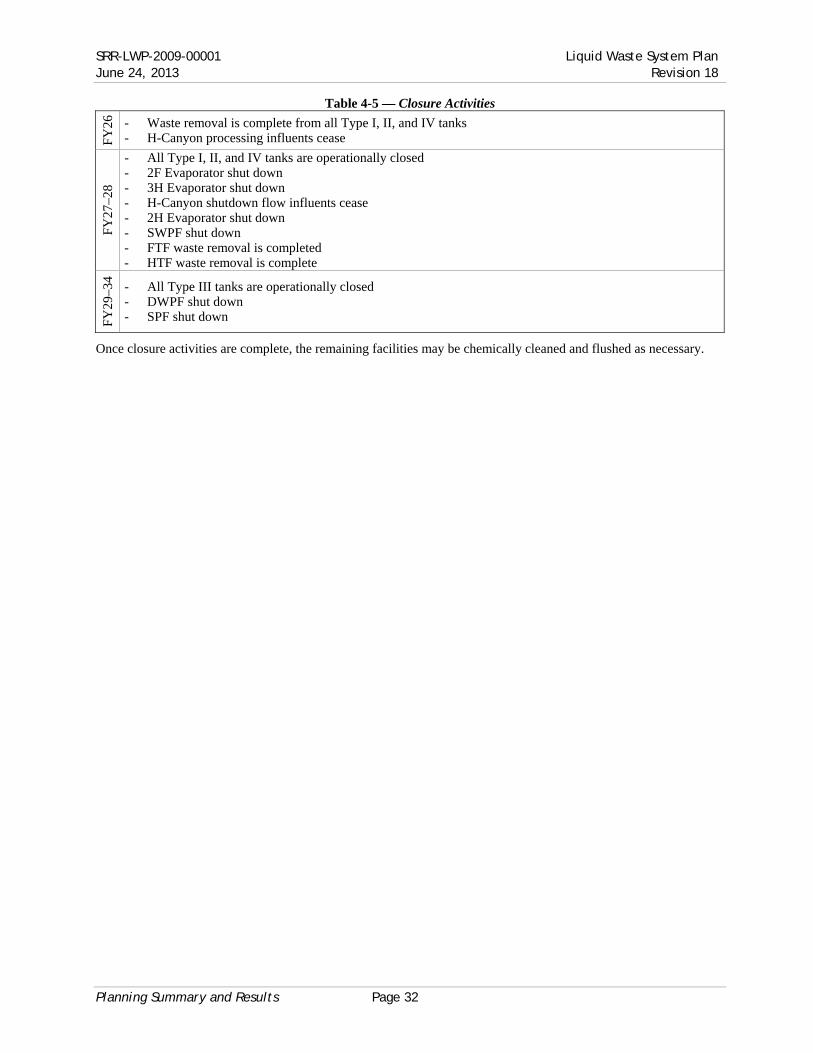
SRR-LWP-2009-00001 Liquid Waste System Plan June 24, 2013 Revision 18
Planning Summary and Results Page 32
Table 4-5 — Closure Activities F
Y26
- Waste removal is complete from all Type I, II, and IV tanks - H-Canyon processing influents cease
FY
27–2
8
- All Type I, II, and IV tanks are operationally closed - 2F Evaporator shut down - 3H Evaporator shut down - H-Canyon shutdown flow influents cease - 2H Evaporator shut down - SWPF shut down - FTF waste removal is completed - HTF waste removal is complete
FY
29–3
4
- All Type III tanks are operationally closed - DWPF shut down - SPF shut down
Once closure activities are complete, the remaining facilities may be chemically cleaned and flushed as necessary.

Liquid Waste System Plan SRR-LWP-2009-00001 Revision 18 June 24, 2013
Page 33 Alternative Analyses
Alternate Case
Base Case
0%
10%
20%
30%
40%
50%
60%
70%
80%
90%
100%
FY13 FY15 FY17 FY19 FY21 FY23 FY25 FY27 FY29
5. Alternative Analyses
5.1 2023 SWPF Startup
Summary
In this Alternative Analysis, SWPF operations are delayed to October 2023 from October 2018.
Discussion
A five-year delay of the start-up of SWPF operations would allow deferral of Salt Disposition Initiative (SDI) scope to later years, freeing up funding in the near term enabling accelerated deployment of SCIX. This would allow the acceleration of SCIX start-up to October 2016 from April 2019. Additionally, since ARP/MCU is not shut down until six months before SWPF start-up, with additional investment, it could be available at a nominal rate of 4.7 Mgal per year for an additional five years. Delaying the SWPF operations would allow greater processing in the FY17 through FY23 timeframe due to continuous processing through that period. It would, however, delay processing in the later years (see Figure 5-1).
The increased production in SCIX and ARP/MCU results in a balanced treatment of the salt waste approximately evenly between the three major facilities (see Appendix H — Salt Solution Processing, Alternate Case). SWPF processing finishes in early FY29 as compared to FY26 in the base case and SCIX processing finishes early FY29 as compared to mid FY28 in the base case. While canister production would be similar to the base case, Type I, II, and IV tank closures would be further delayed (see Figure 5-2 and Appendix I — BWRE & Removal from Service, Alternate Case).
SDU-7 would be required a year earlier than in the base case, SDU-8 would be required eight months earlier, and SDU-9 would be required about a month earlier. Additionally, since SWPF would operate for a very few years only, there is essentially no positive return to the LW program from the investment in the SWPF Project.
Figure 5-2 — Tank Closure Projections
FY13 FY14 FY15 FY16 FY17 FY18 FY19 FY20 FY21 FY22
jSWPF startup in October 2023 vs. October 2018
FY23 FY24 FY25
FFA Commitment
FY26 FY27 FY28 FY29
21H9H
1F3F
10H
24H
2F
14H
4F
13H
23H
11H
8F
15H
22H
6F5F
7F
12H16H
LWSP, Rev 18 (Base Case)
LWSP, R18 (Alternate Case)
Figure 5-1 — Salt Solution Remaining

SRR-LWP-2009-00001 Liquid Waste System Plan June 24, 2013 Revision 18
Description of Assumptions and Bases Page 34
6. Description of Assumptions and Bases
The major assumptions and planning bases are the results of an agreement between SRR and DOE24. These assumptions address the planning period to the end of the program.
6.1 Priorities for Plan Development ● Continual Safe Storage ● Maximize Risk Reduction through Waste Disposition ● Tank Cleaning and Grouting
6.2 Funding
This Plan was developed assuming the funding required to achieve the planned project and operations activities will be available, within the following restrictions:
● Revision 18 of the Plan assumes receipt of $450M (escalated) new Budget Authority (BA) per year to the LW contractor from FY14 through FY18 and then $525 M (escalated) per year until the end of the program.
● The following items are supplemental to LW contractor funding: SWPF (project and operations), Additional Glass Waste Storage (project and operations), Landlord services, Essential Site Services (ESS - Section J), pension and legacy cost
● No “re-pricing” for site services is realized.
6.3 Regulatory Drivers
The following regulatory requirements drive the development of the System Plan through the end of the program. ● Federal Facility Agreement (FFA) – Commits the Department of Energy to operationally close the Type I,
II, and IV tanks (Tanks 1–24) no later than 2022. The specific schedule for the Type I, II, and IV tanks is per the Statement of Resolution of Dispute Concerning Extension of Closure Dates for Savannah River Site High-Level Radioactive Waste Tanks 19 and 1814, which is the schedule for the currently approved FFA.
● Site Treatment Plan (STP) – “Upon the beginning of full operations, DWPF will maintain canister production sufficient to meet the commitment for the removal of the backlogged and currently generated waste inventory by 2028.” This is satisfied by removing waste (including heels) from all Type III tanks by 2028; Types I, II, and IV having had the waste removed in compliance with the FFA above.
Timely regulatory approvals are necessary to support this Plan.
6.4 Waste Removal and Tank Removal from Service Program
The following technical assumptions were used as input to the modeling of this Plan:
Waste Removal ● Types I, II, and IV tanks (Tanks 1–24):
— Waste Removal and Tank Removal from Service commitments are per the FFA – After completion of bulk waste removal efforts in a specific tank, sufficient liquid may be added to
facilitate heel cleaning and removal. Upon approval by SCDHEC and EPA, other liquids may be stored in the tank after completion of bulk waste removal efforts
● Type III and IIIA (Tanks 25–51) — While the Type III and IIIA tanks are not included in the FFA, commitment for completion of waste
removal (bulk waste and heel) from all (Type I, II, III/IIIA, and IV) tanks is per the STP; tanks are not required to be isolated and grouted to meet the STP
● Waste removal and cleaning activities could include mechanical, chemical, and water washing operations ● After the initial BWRE campaign in a sludge tank, a ~3 to 6 inch heel (10–20 kgal) of waste remains ● After the initial BWRE campaign in a salt tank, ~ 2 to 3 feet (90–130 kgal depending on the type of tank) of
insoluble/low solubility material waste (heel) remains ● Two Phases of Waste Heel Removal are available for use:
— Mechanical Cleaning uses mechanical agitation – Assumed to take three months of operation unless otherwise stated
• Heel solids volume reduced to less than 5 kgal — Chemical Cleaning uses OA or advanced/specialized mechanical or chemical technology

Liquid Waste System Plan SRR-LWP-2009-00001 Revision 18 June 24, 2013
Page 35 Description of Assumptions and Bases
– Assumed to take 6 months of operation unless otherwise stated — For some tanks with high waste turnover, e.g. Tank 8, mechanical cleaning may not be required;
however, flushing could be required prior to chemical cleaning — Tanks 4, 7, 8, 11, 12, 13, 14, 15, 26, 32, 33, 34, 35, 39, 42, 43, 47 are the source tanks for sludge solids
in the model that would have chemical cleaning. No other tanks are planned to have chemical cleaning. — Monitoring during the heel removal phase will inform the decision to do mechanical or chemical
cleaning. — Tank cleaning is complete for Tanks 5 and 6.
Annulus Cleaning ● All tanks that have experienced leaks will undergo inspection and, potentially, sampling and analysis to
determine the necessity for annulus cleaning. The amount of material used for annulus cleaning depends on the extent of waste present.
Tank Removal from Service ● A 29-month operational closure and stabilization process is assumed
— Drying & Sampling (6 months on critical path): including Tank Drying, Sample Prep Documents, Volume Determination Cessation Presentation and Sampling
— Sample Analysis (7 months on critical path): including Lab Analysis and Sample Analysis Report (SAR) — Closure Documentation (11 months on critical path): including DQA, Inventory Determination, Special
Analysis, MEP, Class C Calculation, Closure Module, and Tier 2 — Grouting (5 months on critical path)
● Overall tank closure priority will support area closure in the following order, as feasible: 1. F-Tank Farm 2. H-Tank Farm West Hill 3. H-Tank Farm East Hill
● Stabilization of a waste tank (i.e. grouting of primary tank, annulus space, and cooling coils as specified in the applicable Closure Module) is to be completed within 30 months of receipt of concurrence to enter the residual waste sampling and analysis phase
● Within six months of stabilization, tank waste systems will be removed from the F and H Area High Level Radioactive Waste Tank Farms Construction Permit No. 17424-IW in accordance with the applicable and approved Interim Record of Decision.
Regulatory Approvals ● SCDHEC will approve activities associated with waste removal, stabilization, operational closure, and
maintenance and monitoring of waste tank systems will be performed and completed as described in the Industrial Wastewater General Closure Plan for F-Area Waste Tank Systems25 or the Industrial Wastewater General Closure Plan for H-Area Waste Tank Systems26. Operational closure activities will be performed and completed as described in tank-specific closure modules which are generated per the approved General Closure Plan
● The H-Tank Farm Waste Determination and associated HTF §3116 Basis Document, and the HTF Tier 1 Closure Plan will be approved by DOE in time to support the FY15 FFA tank closure milestones (i.e., Removal from Service of Tanks 12 and 16)
● DOE will approve any necessary waste determination documents to support this Plan ● DOE will maintain NEPA documentation necessary to support this Plan.
6.5 DWPF Production
Canister production and sludge batch need dates are projected by the Sludge Batch Plan15 ● DWPF will produce canisters at maximum throughput for the duration of the program (based on Chemical
Process Cell processing [mercury stripping], achievable melt rate, planned outages, and waste loading for sludge being processed). DWPF near-term canister production is based on revised sludge mass values.
● A four-month melter replacement outage is planned approximately every 96 months of melter operation (i.e., DWPF operates 92 months out of every 96 months).
● The next DWPF melter outage to replace Melter 2 is planned concurrent with replacement of MCU contactors and improvements to achieve the nominal 4.7 Mgal/year ARP/MCU processing rate (March 2015–June 2015). It is planned to include: — Melter #3 will replace Melter #2

SRR-LWP-2009-00001 Liquid Waste System Plan June 24, 2013 Revision 18
Description of Assumptions and Bases Page 36
— DWPF feed preparation modifications — Recycle reduction modifications
– reduce the recycle amount by ~1.25 Mgal/yr from the forecast of ~3.2 Mgal/yr after SWPF startup (as predicted by the algorithm used in versions of the LW System Plan prior to Rev. 15)
● A four-month DWPF outage, beginning June 2018, is required for SWPF tie-ins immediately prior to SWPF becoming operational. During this outage DWPF plans to implement productivity enhancements to support increased influents from SWPF
● Discrete Canister Production Ratei: — Sludge batch planning is performed to recommend the sequencing and timing of future sludge batches.
Based on modeling of sludge batches, Appendix B — Sludge Processing sums the canister production expectations, assuming 275 Discrete canisters/yr
● DWPF recycle is beneficially reused ● Supplemental glass waste storage will be required by December 2017 ● Shipment of canisters off-site for final disposition is not in the scope of this Plan. ● DWPF canisters will maintain a concentration limit of 897 g/m3 of fissile material in the glass27. Sludge batch
preparation will supply feed for the DWPF to ensure the canisters remain within this requirement ● The canister heat load will be less than 834 watts per canister ● Pu discards from H-Canyon will be supported to the extent allowable without negatively impacting planned
canister waste loadings while continuing to comply with the canister fissile material concentration limits.
6.6 Salt Program
ARP/MCU ● ARP/MCU processing rates:
— ARP/MCU processes salt feed at a nominal rate of 3 Mgal/yr — A three-month outage in the fourth quarter of FY13 will allow the transition to a “next generation
solvent” (NGS), enhancing the decontamination factor – Although implementation sets the stage for improved throughput, the improvement is not forecast at
this time so the Plan will initially assume no throughput change with NGS – ISOPAR® levels allow Mode 1
— A 4.7 Mgal/yr nominal throughput is planned after a minimum four-month outage in FY15, coincident with a DWPF melter change-out, to allow for ARP/MCU facility upgrades including: contactor bearings, weir adjustment, ARP filtration improvements (which could include an RMF installation in Tank 41), and throughput improvements
— MCU decontamination factor for Cs-137 is 100–200 prior to NGS – Post-NGS decontamination factor will be greater than 200
● ARP/MCU Operations: – ARP/MCU will not operate during any DWPF melter replacement outages – a four-month ARP/MCU outage to rebuild contactors in every fourth year of operations after 2012 – ARP/MCU will cease operations six months prior to SWPF start-up to allow for SWPF tie-ins – ARP/MCU will not return to operation after SWPF startup
● For each gallon processed, ~1.2 gallons of DSS is sent to SPF ● For each gallon processed, ~0.068 gallons of SE is sent to DWPF ● For each gallon processed, ~1.7 grams of MST is sent to DWPF ● DOE and SCDHEC will approve operation of ARP/MCU facilities to align with the SCDHEC previously
approved date for SWPF startup — the total volume of waste may be increased from the present NDAA §3116 Basis — ARP/MCU facilities operate so as to ensure the total curies emplaced in SDF are within the amount
identified in the SRS LW Strategy10 as amended by letter from the SCDHEC to DOE-SR11 and the Basis for Section 3116 Determination for Salt Waste Disposal at the Savannah River Site7
● Any ARP/MCU facility upgrades required to maintain the ARP/MCU operating rate for its extended life will be provided.
i “Discrete canisters” refers to actual physical canisters (sometimes referred to as cans)

Liquid Waste System Plan SRR-LWP-2009-00001 Revision 18 June 24, 2013
Page 37 Description of Assumptions and Bases
SCIX ● DOE approval will be required prior to the use of SCIX ● SCIX Processing of salt waste begins April 2019 at ~3 Mgal/yr (nominal rate) — this deployment date is
extended due to funding limitations ● The average DSS stream resulting from the SCIX process will be consistent with the NDAA §3116 Basis
Determination for Salt Waste Disposal at SRS. ● Annual processing throughput:
— ~3 Mgal/yr processing rate — The 3 Mgal/yr is based on 100% availability for the Tank Farm feed as well as DWPF and SPF/DSS
Tank receipt of SWPF discharge streams: – For each gallon processed, ~ 1 gallon of DSS is sent to SPF via Tank 50 – For each gallon processed, ~ 8.1 grams of cesium-loaded ion exchange media is sent to DWPF via
Tank 40 – For each gallon processed, ~ 1.7 grams of MST is sent to DWPF via a sludge hub or sludge batch
prep tank ● Tank Farm feed preparation infrastructure modifications are completed to support SCIX processing rates.
Major modifications include: — H-Tank Farm blend tanks readiness for salt solution preparation — Tank 41 readiness as SCIX processing tank — Mixing capabilities — Enhanced transfer capabilities — Transfer routes provided to feed tank.
SWPF ● SWPF becomes operational September 30, 2018
— SWPF tie-ins will require a four-month outage of DWPF operations and a two-month outage of SPF operations
● Annual processing throughput (Long Term Processing Capacity at SWPF – Inputs to System Plan28) — Initial twelve months: 4.625 Mgal/yr processing rate — Second twelve months: 7.2 Mgal/yr nominal processing rate
– The 7 Mgal/yr is based on 100% availability for the Tank Farm feed as well as DWPF and SPF/DSS Tank receipt of SWPF discharge streams • ~8.8 Mgal (nominal rate) of DSS will be sent to SPF per year • ~0.58 Mgal (nominal rate) of SE will be sent to DWPF per year • ~0.16 Mgal (nominal rate) of MST solids/sludge will be sent to DWPF per year
— Subsequent years: 9.0 Mgal/yr nominal processing rate (Note: these rates are based on the use of next generation solvent) • ~11.4 Mgal (nominal rate) of DSS will be sent to SPF per year • ~0.58 Mgal (nominal rate) of SE will be sent to DWPF per year • ~0.20 Mgal (nominal rate) of MST solids/sludge will be sent to DWPF per year
— The SWPF feed chemistry is per SWPF Feed Specification Radionuclide Limits of the SWPF Waste Acceptance Criteria29 including:
• the initial one million gallons of feed to SWPF will be (at 6.44 M Na): – 1.0 Curies per gallon (Ci/gal)
• all batches are planned to be at 6.44 M Na • additional blending may be required to meet other feed criteria, such as:
– OH > 2 M • Caustic (50% NaOH) additions are planned during salt dissolution and batch
preparation, as needed to meet the minimum 2 M OH requirements – Al < 0.25 M – Si < 842 mg/L
● Tank Farm feed preparation infrastructure modifications required to support SWPF processing rates. Major modifications include: — H-Tank Farm Blend tanks readiness for salt solution preparation — F-Tank Farm Blend tanks readiness for salt solution preparation — Tank 49 readiness as SWPF feed tank — Mixing capabilities
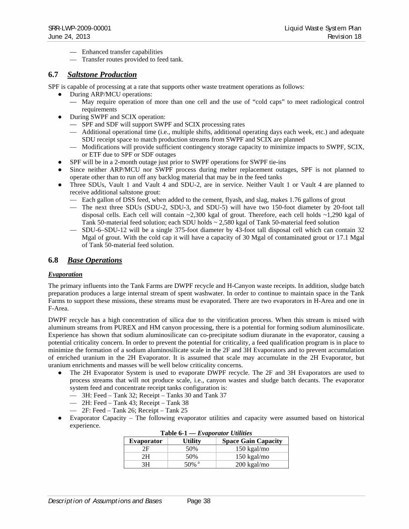
SRR-LWP-2009-00001 Liquid Waste System Plan June 24, 2013 Revision 18
Description of Assumptions and Bases Page 38
— Enhanced transfer capabilities — Transfer routes provided to feed tank.
6.7 Saltstone Production
SPF is capable of processing at a rate that supports other waste treatment operations as follows: ● During ARP/MCU operations:
— May require operation of more than one cell and the use of “cold caps” to meet radiological control requirements
● During SWPF and SCIX operation: — SPF and SDF will support SWPF and SCIX processing rates — Additional operational time (i.e., multiple shifts, additional operating days each week, etc.) and adequate
SDU receipt space to match production streams from SWPF and SCIX are planned — Modifications will provide sufficient contingency storage capacity to minimize impacts to SWPF, SCIX,
or ETF due to SPF or SDF outages ● SPF will be in a 2-month outage just prior to SWPF operations for SWPF tie-ins ● Since neither ARP/MCU nor SWPF process during melter replacement outages, SPF is not planned to
operate other than to run off any backlog material that may be in the feed tanks ● Three SDUs, Vault 1 and Vault 4 and SDU-2, are in service. Neither Vault 1 or Vault 4 are planned to
receive additional saltstone grout: — Each gallon of DSS feed, when added to the cement, flyash, and slag, makes 1.76 gallons of grout — The next three SDUs (SDU-2, SDU-3, and SDU-5) will have two 150-foot diameter by 20-foot tall
disposal cells. Each cell will contain ~2,300 kgal of grout. Therefore, each cell holds ~1,290 kgal of Tank 50-material feed solution; each SDU holds ~ 2,580 kgal of Tank 50-material feed solution
— SDU-6–SDU-12 will be a single 375-foot diameter by 43-foot tall disposal cell which can contain 32 Mgal of grout. With the cold cap it will have a capacity of 30 Mgal of contaminated grout or 17.1 Mgal of Tank 50-material feed solution.
6.8 Base Operations
Evaporation
The primary influents into the Tank Farms are DWPF recycle and H-Canyon waste receipts. In addition, sludge batch preparation produces a large internal stream of spent washwater. In order to continue to maintain space in the Tank Farms to support these missions, these streams must be evaporated. There are two evaporators in H-Area and one in F-Area.
DWPF recycle has a high concentration of silica due to the vitrification process. When this stream is mixed with aluminum streams from PUREX and HM canyon processing, there is a potential for forming sodium aluminosilicate. Experience has shown that sodium aluminosilicate can co-precipitate sodium diuranate in the evaporator, causing a potential criticality concern. In order to prevent the potential for criticality, a feed qualification program is in place to minimize the formation of a sodium aluminosilicate scale in the 2F and 3H Evaporators and to prevent accumulation of enriched uranium in the 2H Evaporator. It is assumed that scale may accumulate in the 2H Evaporator, but uranium enrichments and masses will be well below criticality concerns.
● The 2H Evaporator System is used to evaporate DWPF recycle. The 2F and 3H Evaporators are used to process streams that will not produce scale, i.e., canyon wastes and sludge batch decants. The evaporator system feed and concentrate receipt tanks configuration is: — 3H: Feed – Tank 32; Receipt – Tanks 30 and Tank 37 — 2H: Feed – Tank 43; Receipt – Tank 38 — 2F: Feed – Tank 26; Receipt – Tank 25
● Evaporator Capacity – The following evaporator utilities and capacity were assumed based on historical experience.
Table 6-1 — Evaporator Utilities Evaporator Utility Space Gain Capacity
2F 50% 150 kgal/mo 2H 50% 150 kgal/mo 3H 50% a 200 kgal/mo

Liquid Waste System Plan SRR-LWP-2009-00001 Revision 18 June 24, 2013
Page 39 Description of Assumptions and Bases
a 50% utility is assumed when operating. Due to periodic salt dissolutions and feed availability, average percentage of operating time is lower (<30%).
General Assumptions ● A minor influent is the 299-H Maintenance Facility. The influents mainly consist of a dilute nitric acid
stream, decontamination solutions, and steam condensate. These waste streams are collected from decontaminating equipment and collected in the 299-H pump tank, neutralized and sent to Tank 39.
● Tank Farm infrastructure maintained to support SWPF, DWPF, and SPF processing rates and tank operational closure schedules.
Separations Canyon Operations ● Sufficient tank space volume is available to support the projected receipt of HLW into Tank 39 from
H-Canyon operations through 2025. H-Canyon will transfer shutdown flows in 2026. LLW waste, mainly from the General Purpose Evaporator, dispositioned in SPF are received into Tank 50 and direct discards of Pu and neptunium materials to the DWPF feed system are received into Tank 40, or Tank 51, for which sufficient tank space volume is available.
● Shutdown flows for H-Canyon are assumed from 2026 and are as outlined in H-Canyon Liquid Waste Generation Forecast for H-Tank Farm Transfer30.
● Additional material sent directly to sludge batches increases total DWPF canister count by as much as 100 canisters (these additional canisters are included in the 7,824 forecast canisters of this Plan): — Fissile isotope concentration of SRS HLW canisters will be maintained at or below 897 g/m3 — Pu discards from H-Canyon will be supported to the extent allowable without negatively impacting
planned canister waste loadings while continuing to comply with canister fissile material concentration limits.
Effluent Treatment Facility ● ETF is assumed to receive an average of 11 Mgal/yr:
— LW Evaporators: 5 Mgal/yr — Savannah River Nuclear Solutions (SRNS) Facilities: 6 Mgal/yr
Note: the Agreement between SRNS and SRR for LW Receipt Services provides that the total maximum allocation for waste generated from SRNS facilities including H-Canyon, F-Canyon, the Waste Solidification Building, Mixed Oxide Facility, and miscellaneous smaller contributors is 15 Mgal/yr.
Dismantlement and Decommissioning (D&D) — LW Areas transferred to D&D on an Area-by-Area basis upon closure of their included facilities.

SRR-LWP-2009-00001 Liquid Waste System Plan June 24, 2013 Revision 18
System Description Page 40
7. System Description
7.1 History
The LW System is the integrated series of facilities at SRS that safely manage the existing waste inventory and disposition waste stored in the tanks into a final glass or grout form. This system includes facilities for storage, evaporation, waste removal, pre-treatment, vitrification, and disposal.
Since it became operational in 1951, SRS, a 300-square-mile DOE Complex located in the State of South Carolina, has produced nuclear material for national defense, research, medical, and space programs. The separation of fissionable nuclear material from irradiated targets and fuels resulted in the generation of over 150 Mgal of radioactive waste. As of December 2012, approximately 37 Mgal31 of radioactive waste are currently stored onsite in large underground waste storage tanks at SRS. Most of the tank waste inventory is a complex mixture of chemical and radioactive waste generated during the acid-side separation of special nuclear materials and enriched uranium from irradiated targets and spent fuel using the Plutonium Uranium Reduction Extraction (PUREX) process in F-Canyon and the modified PUREX process in H-Canyon (HM process). Waste generated from the recovery of Pu-238 in H-Canyon for the production of heat sources for space missions is also included. The waste was converted to an alkaline solution; metal oxides settled as sludge, and supernate was evaporated to form saltcake.
The variability in both nuclide and chemical content is because waste streams from the 1st cycle (high heat) and 2nd cycle (low heat) extractions from each Canyon were stored in separate tanks to better manage waste heat generation. When these streams were neutralized with caustic, the resulting precipitate settled into four characteristic sludges presently found in the tanks where they were originally deposited. The soluble portions of the 1st and 2nd cycle waste were similarly partitioned but have and continue to undergo blending in the course of waste transfer and staging of salt waste for evaporative concentration to supernate and saltcake. Historically, fresh waste receipts were segregated into four general categories in the SRS Tank Farms: PUREX high activity waste, PUREX low activity waste, HM high activity wastes and HM low activity wastes. Because of this segregation, settled sludge solids contained in tanks that received fresh waste are readily identified as one of these four categories. Fission product concentrations are about three orders of magnitude higher in both PUREX and HM high-activity waste sludges than the corresponding low-activity waste sludges.
Because of differences in the material processed by PUREX and HM processes, the chemical compositions of principal sludge components (iron, aluminum, uranium, manganese, nickel, and mercury) also vary over a broad range between these sludges. Combining and blending salt solutions has tended to reduce soluble waste into blended salt and concentrate, rather than maintaining four distinct salt compositions. Continued blending and evaporation of the salt solution deposits crystallized salts with overlying and interstitial concentrated salt solution in salt tanks located in both Tank Farms. More recently, with transfers of sludge slurries to sludge washing tanks, removal of saltcake for tank removal from service, receipts of DWPF recycle, and space limitations restricting full evaporator operations, salt solutions have been transferred between the two Tank Farms. Intermingling of PUREX and HM salt waste will continue until high capacity salt waste processing can begin.
Continued long-term storage of these radioactive wastes poses a potential environmental risk. Therefore, since 1996, DOE and its contractor have been removing waste from tanks, pre-treating it, vitrifying it, and pouring the vitrified waste into canisters for long-term disposal in a permanent canister storage location (see Figure 7-2 — Process Flowsheet). As of December 31, 2012, DWPF had produced 3,560 vitrified waste canisters (see Figure 7-3 — Liquid Waste Program — Current Status).
7.2 Tank Storage
SRS has 51 underground waste storage tanks, all of which were placed into operation between 1954 and 1986. There are four types of waste tanks — Types I through IV. Type III tanks are the newest tanks, placed into operation between 1969 and 1986. There are 27 Type III tanks. Type I tanks are the oldest tanks, constructed in 1952 through 1953. Type II waste tanks were constructed in 1955 through 1956. There are eight Type IV tanks, constructed in 1958 through 1962. Four of these Type IV tanks, Tanks 17 through 20 in F-Tank Farm, have been isolated, removed from service, and grouted. Fourteen tanks without full secondary containment have a history of leakage32. As a result of program progress to date, of these 14 SRS tanks (all old-style tanks) with leakage history:
● 2 are operationally closed and grouted ● 2 are empty and cleaned

Liquid Waste System Plan SRR-LWP-2009-00001 Revision 18 June 24, 2013
Page 41 System Description
● 1 has been cleaned, pending further evaluation ● 1 has had bulk waste removed and is undergoing chemical
cleaning later this year ● 1 has had BWRE completed ● 5 contain essentially dry waste, with little or no free liquid
supernate ● 2 contain liquid supernate (at a level well below all known
leak sites)
Of the remaining 10 old-style tanks (none of which have any known leakage history):
● 2 are operationally closed and grouted ● 2 contain essentially dry waste, with little or no free liquid
supernate 6 contain liquid supernate.
When waste disposition began in 1996, the inventory of waste in the SRS tank system contained approximately 550 Million curies. Currently, 36.6 Mgal of radioactive waste, containing 294 million curies (MCi)31 of radioactivity, are stored in 45 active waste storage
tanks located in two separate locations, H-Tank Farm (29 tanks) and F-Tank Farm (18 tanks). This waste is a complex mixture of insoluble metal hydroxide solids, commonly referred to as sludge, and soluble salt supernate. The supernate volume is reduced by evaporation, which also concentrates the soluble salts to their solubility limit. The resultant solution crystallizes as salts. The resulting crystalline solids are commonly referred to as saltcake. The saltcake and supernate combined are referred to as salt waste.
The sludge component of the radioactive waste represents approximately 3.0 Mgal (8% of total) of waste but contains approximately 138 MCi (47% of total). The salt waste makes up the remaining 33.6 Mgal (92% of total) of waste and contains approximately 156 MCi (53% of total). Of that salt waste, the supernate accounts for 17.9 Mgal and 144 MCi and saltcake accounts for the remaining 15.7 Mgal and 12 MCi31. The sludge contains the majority of the long-lived (half-life > 30 years) radionuclides (e.g., actinides) and strontium. The sludge is currently being stabilized in DWPF through a vitrification process that immobilizes the waste in a borosilicate glass matrix.
Radioactive waste volumes and radioactivity inventories reported herein are based on the Waste Characterization System (WCS) database, which includes the chemical and radionuclide inventories on a tank-by-tank basis. WCS is a dynamic database
frequently updated with new data from ongoing operations such as decanting and concentrating of free supernate via evaporators, preparation of sludge batches for DWPF feed, waste transfers between tanks, waste sample analyses, and influent receipts such as H-Canyon waste and DWPF recycle.
Salt waste is dissolved in the liquid portion of the waste. It can be in normal solution as Supernate (top picture) or, after evaporation, as salt cake (bottom picture) or concentrated supernate. The pipes in all
the pictures are cooling coils.
Tanks under construction. Note tank size relative to construction workers. Later, dirt is backfilled
around the tanks to provide shielding.
Sludge consists of insoluble solids that settle to the bottom of a tank. Note the offgas bubbles,
including hydrogen generated from radiolysis.

SRR-LWP-2009-00001 Liquid Waste System Plan June 24, 2013 Revision 18
System Description Page 42
Well over 95%31 of the salt waste radioactivity is short-lived (half-life ≤ 30 years) Cs-137 and its daughter product, Ba-137m, along with lower levels of actinide contamination. Depending on the particular waste stream (e.g., canyon waste, DWPF recycle waste), the cesium concentration may vary. The precipitation of salts following evaporation can also change the cesium concentration. The concentration of cesium is significantly lower than non-radioactive salts in the waste, such as sodium nitrate and nitrite, therefore, the cesium does not reach its solubility limit and only a small fraction precipitates33. As a result, the cesium concentration in the saltcake is much lower than that in the liquid supernate and interstitial liquid fraction of the salt waste.
Figure 7-1 — Waste Tank Composite Inventory (as of December 31, 2012)31
7.3 Waste Tank Space Management
To make better use of available tank storage capacity, incoming liquid waste is evaporated to reduce its volume. This is important because most of the SRS Type III waste storage tanks are already near full capacity. Since 1951, the Tank Farms have received over 150 Mgal of liquid waste, of which over 110 Mgal have been evaporated, leaving approximately 36.6 Mgal in the storage tanks. Projected available tank space is carefully tracked to ensure that the Tank Farms do not become “water logged,” meaning that so much of the usable Type III tank space has been filled that normal operations and waste removal and processing operations cannot continue. A contingency allotment of 1.3 Mgal is not included as working space. This amount is equivalent to the size of the largest tank and is reserved for the unlikely event that a full tank failed such that all its material had to be removed. Waste receipts and transfers are normal Tank Farm activities as the Tank Farms receive new or “fresh” waste from the H-Canyon stabilization program, liquid waste from DWPF processing (typically referred to as “DWPF recycle”), and wash water from sludge washing. The Tank Farms also make routine transfers to and from waste tanks and evaporators. Since initiation of interim salt waste treatment (DAA and ARP/MCU), the working capacity of the Tank Farms has been maintained. Three evaporator systems are currently operating at SRS — the 2H, 3H, and 2F systems.
Space in new-style tanks is used for various operations for waste processing and disposal. Tank space is recovered through evaporator operations, DWPF vitrification, ISDP Treatment, and saltstone disposal. This valuable space has been used to: (1) retrieve waste from and clean old-style tanks; (2) prepare, qualify, and treat sludge waste for disposal; (3) prepare, qualify, treat, and dispose salt waste; and (4) support nuclear materials stabilization and disposal through H-Canyon. The Tank Farm space management strategy is based on a set of key assumptions involving projections of DWPF canister production rates, influent stream volumes, Tank Farm evaporator
Volume
36.6 MillionGallons (Mgal)
Curies
156 MCi(53%)
138 MCi(47%)
294 MillionCuries (MCi)
144 MCi(49%)
33.6 Mgal(92%)
3.0 Mgal(8%)
17.9 Mgal(49%)
12 MCi(4%)
15.7 Mgal(43%)
Sludge
Salt Supernate
Saltcake

Liquid Waste System Plan SRR-LWP-2009-00001 Revision 18 June 24, 2013
Page 43 System Description
performance, and space gain initiative implementation. The processing of salt and sludge utilizes new-style tank space to retrieve and prepare waste from old-style tanks, and therefore nominal empty space in new-style tanks will increase only after all waste in old-style tanks is processed. Sludge processing through the DWPF removes the highest risk material from the old-style tanks. However, for every 1.0 gallon of sludge processed, 1.3 gallons of salt waste is formed due to sludge washing and DWPF processing operations to return the resulting low hazard salt waste to the tank farm. Similarly, salt waste retrieval, preparation, and batching typically require the use of 4 gallons of tank space per gallon of salt waste treated. Given these parameters, the “key to reducing the overall risk is processing high-level waste as expeditiously as possible and managing the total tank space efficiently,” as recognized by the DNFSB letter dated January 7, 2010.
New-style tank space is a currency used to prepare for permanent immobilization and disposition of high level waste in a vitrified waste form and low-level waste in a grouted waste form. Additionally, some “old-style” tanks (e.g., Tank 21–Tank 24) support immobilization and disposition of high-level waste. The tank space management program maintains sufficient space to allow continued DWPF operations. The tank space management program also provides the necessary tank space to support staging of salt solutions to sustain salt waste disposition currently through ARP/MCU and subsequently through SWPF and SCIX. Of the 27 new-style tanks (with a total nominal volume of 35.1 million gallons) in the SRS Liquid Waste System:
● 5 are dedicated to salt batching, qualification, and disposition (including DWPF recycle beneficial reuse and 2H evaporator)
● 6 are dedicated to sludge batching, qualification, and disposition (including 3H evaporator) ● 3 are dedicated to waste retrieval from and residual cleaning of old-style tanks in preparation for operational
closure ● 1 is dedicated to uninterrupted H-Canyon waste receipts ● 12 are dedicated to safe storage of legacy liquid waste pending retrieval and disposition.
There are currently ~6.8 million gallons (Mgals) of empty space (~19%) in these new-style tanks. ● 3.0 Mgals is margin as defense-in-depth operational control coupled with SC/SS SSCs to facilitate
reasonably conservative assurance of more than adequate dilution and ventilation of potentially flammable vapors
● 1.3 Mgals is procedurally-required minimum contingency space for recovery from the unlikely event of a bulk waste leak elsewhere in the system
● 2.5 Mgals is operational “working” space variously used to provide: — Additional contingency transfer space as operational excess margin above the procedurally-required
minimum — Excess margin to preserve salt batch quality and maintain uninterrupted treatment and disposition
through ARP/MCU and Saltstone — Excess margin to preserve sludge batch quality and maintain uninterrupted immobilization through
DWPF — Excess margin to preserve uninterrupted support for H-Canyon.
7.4 Waste Removal from Tanks
The first step in the disposition of sludge and salt waste is bulk waste removal efforts (BWRE). Sludge is sent to a feed preparation tank ensuring sludge waste is continuously available for treatment at DWPF. Salt is dissolved, removed, and staged for treatment at ARP/MCU, SCIX, or SWPF.
To reduce the two-to-four year period required for installation of substantial structural steel and large mixing and transfer pumps — with their attendant infrastructure — required for BWRE, a Waste on Wheels (WOW) innovation was developed. The WOW concept minimizes new infrastructure. Portable and temporary equipment meet tank infrastructure needs. Additional purchased pumps and WOW equipment perform accelerated BWRE operations concurrently in both Tank Farms. The primary components of the WOW system are:
● Long-lasting reusable SMPs ● A portable field operating station containing pump drives and controls ● A portable substation to provide 480-, 240- and 120-volt power to the WOW equipment ● Disposable commercial transfer pumps.

SRR-LWP-2009-00001 Liquid Waste System Plan June 24, 2013 Revision 18
System Description Page 44
WOW equipment is deployed at the tank as a field operating station, providing temporary power and control for BWRE equipment. When BWRE is completed on one tank, the WOW equipment is reconfigured to support waste removal on the next tank. Pumps are sized to fit through 24-inch openings allowing a high degree of flexibility to locate the pumps in optimal configurations within the waste tanks. Most are supported from the bottom of the tank, minimizing steel superstructures and tank-top loading. Product lubricated bearings and motor cooling eliminate the need for bearing and seal water supply. These pumps have exterior fittings and fixtures so that the pumps can be quickly decontaminated, removed, and reinstalled in the next tank with minimal radiation exposure to personnel. Disposable transfer pumps are used to transfer the waste to a receipt or hub tank using existing underground transfer lines and diversion boxes. If the transfer system is degraded or non-existent, above-grade hose-in-hose technology is deployed, rather than investing in costly repairs. Temporary shielding is supplied as necessary to reduce exposure to personnel.
7.5 Safe Disposal of the Waste
The goal is to convert all of the waste into one of two final waste forms: Glass, which will contain 99% of the radioactivity, and Saltstone Grout, which will contain most of the volume. Each of the waste types at SRS needs to be treated to accomplish disposal in these two waste forms. The sludge must be washed to remove non-radioactive salts that would interfere with glass production. The washed sludge can then be sent to DWPF for vitrification. The salt must be treated to separate the bulk of the radionuclides from the non-radioactive salts in the waste. Starting in 2018, this separation will be accomplished in SWPF with SCIX supplementing this separation in 2019. However, until the startup of SWPF and SCIX, ARP/MCU accomplishes this separation.
7.6 Salt Processing
Five different processes treat salt: ● Deliquification, Dissolution, and Adjustment (DDA) –Deliquification (i.e., extracting the interstitial liquid) is
an effective decontamination process because the primary radionuclide in salt is Cs-137, which is highly soluble. To accomplish the process, the salt was first deliquified by draining and pumping. The deliquified salt was then Dissolved by adding water and pumping out the salt solution. The resulting salt solution was aggregated with other Tank Farm waste to Adjust batch chemistry for processing at SPF. For salt in Tank 41 as of June 9, 2003, which was relatively low in radioactive content, treatment using DDA-solely was sufficient to meet the SPF WAC. Tank 41 has since received additional salt dissolution from Tank 25 and there is no longer any qualified feed for the DDA-solely process. No further use of DDA-solely is planned.
● Actinide Removal Process (ARP) – For salt in selected tanks (e.g., Tank 25), even though extraction of the interstitial liquid reduces Cs-137 and soluble actinide concentrations, the Cs-137 or actinide concentrations of the resulting salt are too high to meet the SPF WAC. Salt from these tanks first will be sent to ARP. In ARP, MST is added to the waste as a finely divided solid. Actinides are sorbed on the MST and then filtered out of the liquid to produce a low-level waste stream that is sent to MCU. The MST, containing the actinides, is sent to DWPF.
● Modular CSSX Unit (MCU) – The ARP low-level waste stream requires reduction in the concentration of Cs-137 using the CSSX process. MCU is a solvent extraction process for removal of Cs-137 from caustic salt solutions. The solvent used is a four-part solvent with the key ingredient being the cesium extractant (presently BoB Calix). This solvent is fed to a bank of centrifugal contactors while the waste is fed to the other end in a counter-current flow. The solvent extracts the cesium with each successive contactor stage extracting more, resulting in a DSS stream and a cesium-laden solvent stream. The solvent stream is stripped of its cesium, washed, and the solvent is reused. The cesium-laden strip effluent is transferred to DWPF. MCU has a dual purpose:
WOW Deployment for BWRE

Liquid Waste System Plan SRR-LWP-2009-00001 Revision 18 June 24, 2013
Page 45 System Description
Sample of Vitrified Radioactive Glass
— demonstrating the CSSX flowsheet — treating salt waste to enable accelerated closure of Type I, II, and IV tanks and uninterrupted vitrification
of HLW at DWPF. ● Small Column Ion Exchange (SCIX) – This planned process will use a non-elutable ion exchange media,
crystalline silicotitanate (CST), for use in an ion exchange column (IXC) to remove Cs-137 from the salt solution. Ground CST, laden with Cs-137, is then transferred to a sludge batch for ultimate disposal at DWPF. The DSS stream will be dispositioned at SPF. The MST solids will be transferred to a sludge batch preparation tank for ultimate disposal at DWPF.
● Salt Waste Processing Facility (SWPF) – This is the full-scale CSSX process. This planned facility will incorporate both the ARP and CSSX processes in a full-scale shielded facility capable of handling salt with high levels of radioactivity.
7.7 Sludge Processing
Sludge is washed to reduce the amount of non-radioactive soluble salts remaining in the sludge slurry. During sludge processing, large volumes of wash water are generated and must be volume-reduced by evaporation or beneficially reused. Over the life of the waste removal program, the sludge currently stored in tanks at SRS will be blended into separate sludge batches to be processed and fed to DWPF for vitrification.
7.8 DWPF Vitrification
Final processing for the washed sludge and salt waste occurs at DWPF. This waste includes MST/sludge from ARP or SWPF, the cesium strip effluent from MCU or SWPF, and the washed sludge slurry. In a complex sequence of carefully controlled chemical reactions, this waste is blended with glass frit and melted to vitrify it into a borosilicate glass form. The resulting molten glass is poured into stainless steel canisters. As the filled canisters cool, the molten glass solidifies, immobilizing the radioactive waste within the glass structure. After the canisters have cooled, they are first sealed with a temporary plug, the external surfaces are decontaminated to meet United States Department of Transportation requirements, and the canister is then permanently sealed. The canisters are then ready to be stored on an interim basis on-site. Additional glass waste storage space will be needed by December 2016. A low-level recycle waste stream from DWPF is returned to the Tank Farms. DWPF has been operational since 1996.
7.9 Saltstone Disposition
The Saltstone Facility, located in Z-Area, consists of two facility segments: the Saltstone Production Facility (SPF) and the Saltstone Disposal Facility (SDF). SPF is permitted as a wastewater treatment facility per SCDHEC regulations. SPF receives and treats the salt solution to produce grout by mixing the LLW liquid stream with cementitious materials (cement, flyash, and slag). A slurry of the components is pumped into the SDUs, located in SDF, where the Saltstone grout solidifies into a monolithic, non-hazardous, solid LLW form. SDF is permitted as an Industrial Solid Waste Landfill site.
Future salt waste processing will impose significantly greater production demands. After SWPF startup, feed of decontaminated salt solution to the SPF could reach as high as 12.8 Mgal/year. In anticipation of this future demand,
View of the Saltstone Facility
Canisters being received (prior to being filled with radioactive glass)
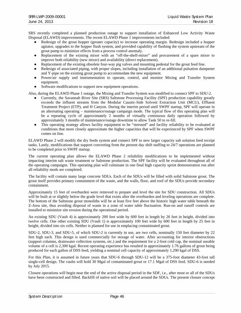
SRR-LWP-2009-00001 Liquid Waste System Plan June 24, 2013 Revision 18
System Description Page 46
SRS recently completed a planned production outage to support installation of Enhanced Low Activity Waste Disposal (ELAWD) improvements. The recent ELAWD Phase 1 improvements included:
● Redesign of the grout hopper (greater capacity) to increase operating margin. Redesign included a hopper agitator, upgrades to the hopper flush system, and provided capability of flushing the system upstream of the grout pump to minimize effects from a process control anomaly.
● Replacement of the existing mixer with an “off-the-shelf-mixer” and procurement of a spare mixer to improve both reliability (new mixer) and availability (direct replacement).
● Replacement of the existing obsolete four-way pig valves and mounting pedestal for the grout feed line. ● Redesign of associated piping, with proper slopes, including installation of an additional pulsation dampener
and Y-pipe on the existing grout pump to accommodate the new equipment. ● Power/air supply and instrumentation to operate, control, and monitor Mixing and Transfer System
equipment. ● Software modifications to support new equipment operations.
Also, during the ELAWD Phase 1 outage, the Mixing and Transfer System was modified to connect SPF to SDU-2. ● Currently, the Savannah River Site (SRS) Saltstone Processing Facility (SPF) production capability greatly
exceeds the influent streams from the Modular Caustic-Side Solvent Extraction Unit (MCU), Effluent Treatment Project (ETP), and H Canyon. During the interim period until SWPF startup, SPF will operate in an alternating operating – maintenance/outage campaign mode. The typical flow of this operating plan will be a repeating cycle of approximately 2 months of virtually continuous daily operation followed by approximately 3 months of maintenance/outage downtime to allow Tank 50 to re-fill.
● This operating strategy allows facility equipment to be “stressed” and facility reliability to be evaluated at conditions that more closely approximate the higher capacities that will be experienced by SPF when SWPF comes on line.
ELAWD Phase 2 will modify the dry feeds system and connect SPF to new larger capacity salt solution feed receipt tanks. Lastly, modifications that support converting from the present day shift staffing to 24/7 operations are planned to be completed prior to SWPF startup.
The current operating plan allows the ELAWD Phase 2 reliability modifications to be implemented without impacting interim salt waste treatment or Saltstone production. The SPF facility will be evaluated throughout all of the operating campaigns. This operating plan will culminate in one final high capacity sprint demonstration run after all reliability mods are completed.
The facility will contain many large concrete SDUs. Each of the SDUs will be filled with solid Saltstone grout. The grout itself provides primary containment of the waste, and the walls, floor, and roof of the SDUs provide secondary containment.
Approximately 15 feet of overburden were removed to prepare and level the site for SDU construction. All SDUs will be built at or slightly below the grade level that exists after the overburden and leveling operations are complete. The bottom of the Saltstone grout monoliths will be at least five feet above the historic high water table beneath the Z-Area site, thus avoiding disposal of waste in a zone of water table fluctuation. Run-on and runoff controls are installed to minimize site erosion during the operational period.
An existing SDU (Vault 4) is approximately 200 feet wide by 600 feet in length by 26 feet in height, divided into twelve cells. One other existing SDU (Vault 1) is approximately 100 feet wide by 600 feet in length by 25 feet in height, divided into six cells. Neither is planned for use in emplacing contaminated grout.
SDU-2, SDU-3, and SDU-5, of which SDU-2 is currently in use, are two cells, nominally 150 feet diameter by 22 feet high each. This design is used commercially for storage of water. After accounting for interior obstructions (support columns, drainwater collection systems, etc.) and the requirement for a 2-foot cold cap, the nominal useable volume of a cell is 2,300 kgal. Recent operating experience has resulted in approximately 1.76 gallons of grout being produced for each gallon of DSS feed, yielding a nominal cell capacity of approximately 1,290 kgal of DSS.
For this Plan, it is assumed in future years that SDU-6 through SDU-12 will be a 375-foot diameter 43-foot tall single-cell design. The vaults will hold 30 Mgal of contaminated grout or 17.1 Mgal of DSS feed. SDU-6 is needed by July 2015.
Closure operations will begin near the end of the active disposal period in the SDF, i.e., after most or all of the SDUs have been constructed and filled. Backfill of native soil will be placed around the SDUs. The present closure concept

Liquid Waste System Plan SRR-LWP-2009-00001 Revision 18 June 24, 2013
Page 47 System Description
includes two moisture barriers consisting of clay/gravel drainage systems along with backfill layers and a shallow-rooted bamboo vegetative cover.
Construction of the SDF and the first two SDUs was completed between February 1986 and July 1988. The SDF started radioactive operations June 12, 1990. SDU-2 began filling in September 2012. SDU-3 and SDU-5 are planned to begin filling in October 2013. Future SDUs will be constructed on a “just-in-time” basis in coordination with salt processing production rates.

SRR-LWP-2009-00001 Liquid Waste System Plan June 24, 2013 Revision 18
System Description Page 48
Figure 7-2 — Process Flowsheet

Liquid Waste System Plan SRR-LWP-2009-00001 Revision 18 June 24, 2013
Page 49 System Description
Figure 7-3 — Liquid Waste Program — Current Status
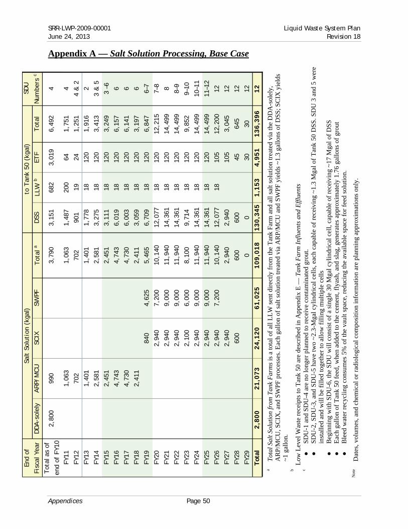
SRR-LWP-2009-00001 Liquid Waste System Plan June 24, 2013 Revision 18
Appendices Page 50
Appendix A — Salt Solution Processing, Base Case
Tot
al S
alt S
olut
ion
from
Tan
k F
arm
s is
a to
tal o
f al
l LL
W s
ent d
irec
tly
from
the
Tan
k F
arm
and
all
sal
t sol
utio
n tr
eate
d vi
a th
e D
DA
-sol
ely,
A
RP
/MC
U, S
CIX
, and
SW
PF
pro
cess
es. E
ach
gallo
n of
sal
t sol
utio
n tr
eate
d vi
a A
RP
/MC
U a
nd S
WP
F y
ield
s ~1
.3 g
allo
ns o
f D
SS
; SC
IX y
ield
s ~1
gal
lon.
Low
Lev
el W
aste
rec
eipt
s to
Tan
k 50
are
des
crib
ed in
App
endi
x E
— T
ank
Far
m I
nflu
ents
and
Eff
luen
ts
●
SD
U-1
and
SD
U-4
are
no
long
er p
lann
ed to
rec
eive
con
tam
inat
ed g
rout
. ●
S
DU
-2, S
DU
-3, a
nd S
DU
-5 h
ave
two
~2.3
-Mga
l cyl
indr
ical
cel
ls, e
ach
capa
ble
of r
ecei
ving
~1.
3 M
gal o
f T
ank
50 D
SS
. SD
U 3
and
5 w
ere
inst
alle
d an
d w
ill b
e fi
lled
toge
ther
to a
llow
fil
ling
mul
tipl
e ce
lls
●
Beg
inni
ng w
ith
SD
U-6
, the
SD
U w
ill c
onsi
st o
f a
sing
le 3
0 M
gal c
ylin
dric
al c
ell,
capa
ble
of r
ecei
ving
~17
Mga
l of
DS
S
●
Eac
h ga
llon
of T
ank
50 f
eed,
whe
n ad
ded
to th
e ce
men
t, fl
yash
, and
sla
g, g
ener
ates
app
roxi
mat
ely
1.76
gal
lons
of
grou
t ●
B
leed
wat
er r
ecyc
ling
con
sum
es 5
% o
f th
e va
ult s
pace
, red
ucin
g th
e av
aila
ble
spac
e fo
r fe
ed s
olut
ion.
Dat
es, v
olum
es, a
nd c
hem
ical
or
radi
olog
ical
com
posi
tion
info
rmat
ion
are
plan
ning
app
roxi
mat
ions
onl
y.
a b c
Not
e
Salt
Sol
utio
n (k
gal)
to T
ank
50 (
kgal
)
DD
A-s
olel
yA
RP/
MC
U
SCIX
SW
PFT
otal
aD
SSLL
W b
ETF
Tot
al
Tot
al a
s of
end
of F
Y10
2,80
099
03,
790
3,15
168
23,
019
6,49
24
FY11
1,06
31,
063
1,48
720
064
1,75
14
FY12
702
702
901
1924
1,25
14
& 2
FY13
1,40
11,
401
1,77
818
120
1,91
62
FY14
2,58
12,
581
3,27
518
120
3,41
33
& 5
FY15
2,45
12,
451
3,11
118
120
3,24
93
–6
FY16
4,74
34,
743
6,01
918
120
6,15
76
FY17
4,73
04,
730
6,00
318
120
6,14
16
FY18
2,41
12,
411
3,05
918
120
3,19
76
FY19
840
4,62
55,
465
6,70
918
120
6,84
76–
7
FY20
2,94
07,
200
10,1
4012
,077
1812
012
,215
7–8
FY21
2,94
09,
000
11,9
4014
,361
1812
014
,499
8
FY22
2,94
09,
000
11,9
4014
,361
1812
014
,499
8–9
FY23
2,10
06,
000
8,10
09,
714
1812
09,
852
9–10
FY24
2,94
09,
000
11,9
4014
,361
1812
014
,499
10–1
1
FY25
2,94
09,
000
11,9
4014
,361
1812
014
,499
11–1
2
FY26
2,94
07,
200
10,1
4012
,077
1810
512
,200
12
FY27
2,94
02,
940
2,94
010
53,
045
12
FY28
600
600
600
4564
512
FY29
00
3030
12
Tot
al2
,80
02
1,0
73
24
,12
06
1,0
25
10
9,0
18
13
0,3
45
1,1
53
4,9
51
13
6,3
96
12
End
of
Fisc
al Y
ear
SDU
Num
bers
c
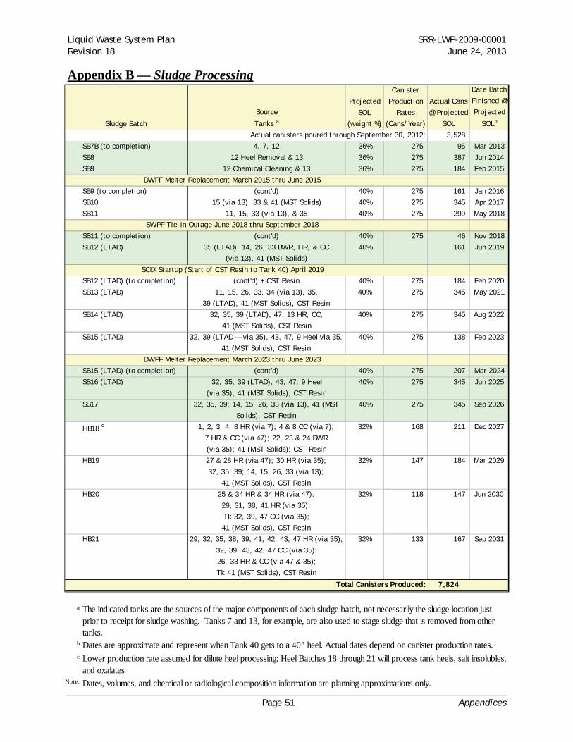
Liquid Waste System Plan SRR-LWP-2009-00001 Revision 18 June 24, 2013
Page 51 Appendices
Appendix B — Sludge Processing
Source
Tanks a
Projected
SOL
(weight %)
Canister
Production
Rates
(Cans/Year)
Actual Cans
@ Projected
SOL
Date Batch
Finished @
Projected
SOLb
Actual canisters poured through September 30, 2012: 3,528
SB7B (to completion) 4, 7, 12 36% 275 95 Mar 2013
SB8 12 Heel Removal & 13 36% 275 387 Jun 2014
SB9 12 Chemical Cleaning & 13 36% 275 184 Feb 2015
DWPF Melter Replacement March 2015 thru June 2015
SB9 (to completion) (cont'd) 40% 275 161 Jan 2016
SB10 15 (via 13), 33 & 41 (MST Solids) 40% 275 345 Apr 2017
SB11 11, 15, 33 (via 13), & 35 40% 275 299 May 2018
SWPF Tie-In Outage June 2018 thru September 2018
SB11 (to completion) (cont'd) 40% 275 46 Nov 2018
SB12 (LTAD) 35 (LTAD), 14, 26, 33 BWR, HR, & CC
(via 13), 41 (MST Solids)
40% 161 Jun 2019
SCIX Startup (Start of CST Resin to Tank 40) April 2019
SB12 (LTAD) (to completion) (cont'd) + CST Resin 40% 275 184 Feb 2020
SB13 (LTAD) 11, 15, 26, 33, 34 (via 13), 35,
39 (LTAD), 41 (MST Solids), CST Resin
40% 275 345 May 2021
SB14 (LTAD) 32, 35, 39 (LTAD), 47, 13 HR, CC,
41 (MST Solids), CST Resin
40% 275 345 Aug 2022
SB15 (LTAD) 32, 39 (LTAD — via 35), 43, 47, 9 Heel via 35,
41 (MST Solids), CST Resin
40% 275 138 Feb 2023
DWPF Melter Replacement March 2023 thru June 2023
SB15 (LTAD) (to completion) (cont'd) 40% 275 207 Mar 2024
SB16 (LTAD) 32, 35, 39 (LTAD), 43, 47, 9 Heel
(via 35), 41 (MST Solids), CST Resin
40% 275 345 Jun 2025
SB17 32, 35, 39; 14, 15, 26, 33 (via 13), 41 (MST
Solids), CST Resin
40% 275 345 Sep 2026
HB18 c 1, 2, 3, 4, 8 HR (via 7); 4 & 8 CC (via 7);
7 HR & CC (via 47); 22, 23 & 24 BWR
(via 35); 41 (MST Solids); CST Resin
32% 168 211 Dec 2027
HB19 27 & 28 HR (via 47); 30 HR (via 35);
32, 35, 39; 14, 15, 26, 33 (via 13);
41 (MST Solids), CST Resin
32% 147 184 Mar 2029
HB20 25 & 34 HR & 34 HR (via 47);
29, 31, 38, 41 HR (via 35);
Tk 32, 39, 47 CC (via 35);
41 (MST Solids), CST Resin
32% 118 147 Jun 2030
HB21 29, 32, 35, 38, 39, 41, 42, 43, 47 HR (via 35);
32, 39, 43, 42, 47 CC (via 35);
26, 33 HR & CC (via 47 & 35);
Tk 41 (MST Solids), CST Resin
32% 133 167 Sep 2031
Total Canisters Produced: 7,824
a
b
c
Note:
Sludge Batch
The indicated tanks are the sources of the major components of each sludge batch, not necessarily the sludge location just prior to receipt for sludge washing. Tanks 7 and 13, for example, are also used to stage sludge that is removed from other tanks.Dates are approximate and represent when Tank 40 gets to a 40″ heel. Actual dates depend on canister production rates.
Lower production rate assumed for dilute heel processing; Heel Batches 18 through 21 will process tank heels, salt insolubles, and oxalates
Dates, volumes, and chemical or radiological composition information are planning approximations only.

SRR-LWP-2009-00001 Liquid Waste System Plan June 24, 2013 Revision 18
Appendices Page 52
Appendix C — Canister Storage
Yearly Cum. Added Cum. Added Cum. Addedd Cum.
FY96 64 64 64 64
FY97 169 233 169 233
FY98 250 483 250 483
FY99 236 719 236 719
FY00 231 950 231 950
FY01 227 1,177 227 1,177
FY02 160 1,337 160 1,337
FY03 115 1,452 115 1,452
FY04 260 1,712 260 1,712
FY05 257 1,969 257 1,969
FY06 245 2,214 244 2,213 1 1
FY07 160 2,374 28 2,241 132 133
FY08 225 2,599 2,241 225 358
FY09 196 2,795 2,241 196 554
FY10 192 2,987 3 2,244 183 737
FY11 264 3,251 2,244 260 997
FY12 277 3,528 2,244 277 1,269
FY13 275 3,803 2,244 275 1,544
FY14 276 4,079 2,244 276 1,820
FY15 184 4,263 2,244 184 2,004
FY16 276 4,539 2,244 276 2,280
FY17 276 4,815 2,244 59 2,339 217 217
FY18 184 4,999 2,244 2,339 184 401
FY19 276 5,275 2,244 2,339 276 677
FY20 276 5,551 2,244 2,339 276 953
FY21 276 5,827 2,244 2,339 276 1,229
FY22 276 6,103 2,244 2,339 276 1,505
FY23 184 6,287 2,244 2,339 184 1,689
FY24 276 6,563 2,244 2,339 276 1,965
FY25 276 6,839 2,244 2,339 276 2,241
FY26 276 7,115 2,244 2,339 276 2,517
FY27 169 7,284 2,244 2,339 169 2,686
FY28 153 7,437 2,244 2,339 153 2,839
FY29 132 7,569 2,244 2,339 132 2,971
FY30 122 7,691 2,244 2,339 122 3,093
FY31 133 7,824 2,244 2,339 133 3,226
FY32 7,824 2,244 2,339 15 3,241
a
b
c
d
Note: Dates, volumes, and chemical or radiological composition information are planning approximations only.
GWSB #1 filling began in May 1996. Of 2,262 standard canister storage locations, 8 are unusable and 3 store non-radioactive archive canisters yielding a usable storage capacity of 2,251 standard canisters; 7 are contingency positions for placement of canisters if GWSB #2 is temporarily unavailable. It reached its maximum capacity in FY07.
GWSB #2 was built with 2,340 standard storage locations. One archived non-radioactive canister is stored in GWSB #2 yielding a usable storage capacity of 2,339 standard canisters. GWSB #2 received its first radioactive canister in June 2006. It is expected to reach maximum capacity in FY17.
This Plan assumes supplemental canister storage is available in early FY17.
End of
Fiscal
Year
SRS Cans
Produced
SRS Cans in GWSB #1
(2,251 capacity)a
SRS Cans in GWSB #2
(2,339 capacity)b
SRS Cans in
Supplemental Storage c
Typically, five to ten canisters are in the vitirification building pending transfer to canister storage. All cans will be transferred to canister storage before the DWPF is cleaned and flushed.
Numbers in italics are actuals — through FY11. FY12 and on are forecast based on modeling assumptions

Liquid Waste System Plan SRR-LWP-2009-00001 Revision 18 June 24, 2013
Page 53 Appendices
Appendix D — BWRE & Removal from Service, Base Case
Bulk Waste Removal Efforts
Tank Removal from Service
FY23 FY24FY13 FY14 FY15 FY16 FY17 FY18 FY19 FY20 FY21 FY22
Tanks 4F*, 5F, 6F, 7F*, 8F*, 11H*, 12H, 16H, 17F, 18F, 19F, and 20F Bulk Waste Removal Efforts Complete
FFA Commitment
LWSP, Rev 18
23H*
1F
24H*
10H
2F9H
21H*
22H*
14H
3F
13H
15H
* These tanks are planned for continued usage after the BWRE milestones are complete. EPA and SCDHEC concurred with the continued use of Tank 8, 7 and 11. Tanks 4, 7, and 8 are under discussion for expanded continued use. Tanks 21–24 will be reviewed with SCDHEC and EPA at the appropriate time.
FY13 FY14 FY15 FY16 FY17 FY18 FY19 FY20 FY21 FY22 FY23 FY24 FY25
FFA Commitment
LWSP, Rev 18
FY26 FY27 FY28
21H9H
1F3F
10H
24H
2F
14H
4F
13H
23H
11H
8F
15H
22H
6F5F
7F
12H16H
LWSP, Rev 18 w/ funding constraint

SRR-LWP-2009-00001 Liquid Waste System Plan June 24, 2013 Revision 18
Appendices Page 54
Appendix E — Tank Farm Influents and Effluents
Effl
uen
ts (
kgal
)
LW
LLW
Oth
er M
at'lb
FY
13
3
00
18
10
1,91
2
1
2
120
1,
916
3
63
35
,68
7
FY
14
3
00
18
-
2,0
49
12
1
20
3,41
3
354
3
4,1
13
FY
15
3
00
18
-
1,5
20
12
1
20
3,24
9
254
3
3,3
82
FY
16
3
00
18
-
2,2
13
12
1
20
6,15
7
420
3
0,0
61
FY
17
3
00
18
-
2,2
13
12
1
20
6,14
1
420
2
6,8
60
FY
18
3
00
18
-
1,4
48
12
1
20
3,13
1
284
2
6,1
24
FY
19
3
00
18
-
2,4
01
12
1
20
6,84
7
397
2
2,9
41
FY
20
3
00
18
-
2,6
50
12
1
20
12
,215
384
2
1,5
42
FY
21
3
00
18
2,82
3
1
2
120
12,2
15
3
75
18
,37
3
FY
22
3
00
18
2,82
3
1
2
120
15,0
07
3
75
14
,26
4
FY
23
3
00
18
2,06
0
1
2
120
9,
852
2
54
10
,86
6
FY
24
3
00
18
2,82
3
1
2
120
15,0
07
3
80
8
,74
0
FY
25
3
00
18
2,82
3
1
2
120
15,0
07
3
81
6
,05
0
FY
26
1
95
18
2,62
2
1
2
105
12,5
81
3
89
3
,35
7
FY
27
-
-
1,20
3 d
105
3,
045
1
95
2
,15
0
FY
28
-
4
5
1,
045
1
68
3
30
FY
29
30
30
1
36
2
73
FY
30
30
-
123
1
00
FY
31
30
-
151
25
FY
32
-
-
-
End
of
Fis
cal
Yea
rET
F29
9-H
Tot
a l
Inve
nto
rye
Infl
uen
ts (
kgal
)
H-C
anyo
naSl
udge
to
DW
PFD
SS t
o SP
F
DW
PF
Rec
ycle
c

Liquid Waste System Plan SRR-LWP-2009-00001 Revision 18 June 24, 2013
Page 55 Appendices
H
-Can
yon
rece
ipts
are
bas
ed o
n L
ing-
to-B
lack
mon
34 f
or t
he d
urat
ion
and
the
Liq
uid
Was
te F
unct
iona
l Se
rvic
e A
gree
men
t35 b
etw
een
SR
NS
and
SR
R f
or t
he v
olum
e. T
he s
hutd
own
flow
vol
ume
for
H-C
anyo
n, a
s ou
tlin
ed i
n H
-Can
yon
Liq
uid
Was
te G
ener
atio
n F
orec
ast
For
H-T
ank
Far
mT
rans
fer30
, is
assu
med
in F
Y26
.
LW
is th
e m
ain
com
pone
nt o
f H
-Can
yon
was
te a
nd is
rec
eive
d in
to T
ank
39
L
LW
con
sist
s pr
imar
ily
of G
ener
al P
urpo
se (
GP
) H
-Can
yon
Eva
pora
tor
conc
entr
ate
rece
ived
in T
ank
50
O
ther
mat
eria
ls, w
hich
may
incl
ude
uran
ium
, plu
toni
um, n
eptu
nium
, etc
., ar
e re
ceiv
ed d
irec
tly
into
slu
dge
batc
hes,
via
eit
her
the
slud
ge
prep
arat
ion
tank
(T
ank
51)
or th
e D
WP
F f
eed
tank
(T
ank
40).
V
ario
us n
ucle
ar m
ater
ials
, inc
ludi
ng p
luto
nium
, ura
nium
, nep
tuni
um, e
tc.,
from
H-C
anyo
n m
ay b
e in
trod
uced
into
slu
dge
batc
hes
to th
e ex
tent
al
low
able
with
out n
egat
ivel
y im
pact
ing
plan
ned
cani
ster
was
te lo
adin
gs w
hile
con
tinui
ng to
com
ply
with
the
cani
ster
fis
sile
mat
eria
l co
ncen
trat
ion
lim
its.
At t
he ti
me
of p
ubli
cati
on o
f th
is P
lan,
H-C
anyo
n di
d no
t hav
e a
fore
cast
for
pro
cess
ing
this
mat
eria
l pas
t FY
13. T
he H
-C
anyo
n fo
reca
st f
or th
ese
mat
eria
ls w
ill b
e in
clud
ed in
fut
ure
vers
ions
of
this
Pla
n, a
s it
is m
ade
avai
labl
e.
DW
PF
Rec
ycle
rec
eipt
s re
flec
t mod
ific
atio
ns m
ade
in th
e D
WP
F to
red
uce
recy
cle.
Add
itio
nall
y, D
WP
F r
ecyc
le is
use
d to
min
imiz
e in
hibi
ted
wat
er a
ddit
ion
requ
ired
for
sal
t dis
solu
tion
and
mol
arit
y ad
just
men
ts w
ithi
n th
e T
ank
Far
ms.
Mai
nten
ance
Fac
ilit
y (2
99-H
) re
ceip
ts m
ainl
y co
nsis
ts o
f a
dilu
te n
itri
c ac
id s
trea
m, d
econ
sol
utio
ns, a
nd s
team
con
dens
ate.
The
se w
aste
st
ream
s fr
om d
econ
tam
inat
ing
equi
pmen
t are
col
lect
ed in
the
299-
H p
ump
tank
, neu
tral
ized
, and
sen
t to
Tan
k 39
. The
y ar
e as
sum
ed to
be
redi
rect
ed w
hen
nece
ssar
y to
com
plet
e T
ank
39 h
eel r
emov
al.
Vol
umes
are
not
add
itiv
e af
ter
acco
unti
ng f
or je
t dil
utio
n, e
xpan
sion
of
slud
ge d
urin
g sl
udge
slu
rryi
ng o
pera
tion
s (s
ludg
e be
com
es le
ss d
ense
),
and
othe
r vo
lum
e ch
ange
s du
ring
the
proc
essi
ng o
f w
aste
. Dur
ing
a tr
ansf
er, s
team
edu
ctor
jets
are
use
d to
tran
sfer
liqu
id w
aste
fro
m ta
nk to
ta
nk. V
olum
e fr
om th
e tr
ansf
er s
team
acc
ount
s fo
r 4%
of
the
volu
me
bein
g tr
ansf
erre
d fo
r in
tra-
area
tran
sfer
s an
d 6%
for
inte
r-ar
ea li
nes.
M
ixin
g w
aste
for
ms
of d
iffe
rent
com
posi
tion
s ar
e no
t mat
hem
atic
ally
add
itiv
e. F
or e
xam
ple,
not
icea
ble
spac
e re
cove
ry c
an b
e ac
hiev
ed w
hen
a lig
ht s
olut
ion
(suc
h as
DW
PF
rec
ycle
wat
er)
is m
ixed
with
con
cent
rate
d su
pern
ate.
Als
o, th
e di
ssol
utio
n of
“dr
y sa
lt”
(i.e
. sal
t with
in
ters
titi
al li
quid
rem
oved
) te
nds
to r
ecov
er s
pace
. Yea
rs w
ith
larg
e am
ount
s of
sal
t dis
solu
tion
ref
lect
this
ano
mal
y.
Dat
es, v
olum
es, a
nd c
hem
ical
or
radi
olog
ical
com
posi
tion
info
rmat
ion
are
plan
ning
app
roxi
mat
ions
onl
y.
a b c d e
Not
e

SRR-LWP-2009-00001 Liquid Waste System Plan June 24, 2013 Revision 18
Appendices Page 56
Appendix F — Remaining Tank Inventory
Tot
al R
emai
nin
g In
vento
ry
(Typ
e I,
II,
III/I
IIA,
& IV
)
Rem
ainin
g T
ype
I, II,
& IV
In
vento
ry
010203040
Oct ′13
Oct ′14
Oct ′15
Oct ′16
Oct ′17
Oct ′18
Oct ′19
Oct ′20
Oct ′21
Oct ′22
Oct ′23
Oct ′24
Oct ′25
Oct ′26
Oct ′27
Oct ′28
Oct ′29
Oct ′30
Oct ′31
millions of gallons
Rem
ainin
g Ta
nk
Inve
nto
ry

Liquid Waste System Plan SRR-LWP-2009-00001 Revision 18 June 24, 2013
Page 57 Appendices
Appendix G — LW System Plan — Rev 18 Summary
(see attached foldout chart)

SRR-LWP-2009-00001 Liquid Waste System Plan June 24, 2013 Revision 18
Appendices Page 58
Appendix H — Salt Solution Processing, Alternate Case
Sa
lt S
olut
ion
(kga
l)to
Tan
k 50
(kg
al)
DD
A-s
olel
yA
RP/
MC
U
SCIX
SW
PFT
otal
DSS
LLW
ETF
Tot
al
Tot
al a
s of
end
of F
Y10
2,80
099
03,
790
3,15
168
23,
019
6,49
24
FY11
1,06
31,
063
1,48
720
064
1,75
14
FY12
702
702
901
1924
1,25
14
& 2
FY13
1,40
11,
401
1,77
818
120
1,91
62
FY14
2,58
12,
581
3,27
518
120
3,41
33
& 5
FY15
2,45
12,
451
3,11
118
120
3,24
93
–6
FY16
4,70
04,
700
5,96
418
120
6,10
26
FY17
4,70
02,
940
7,64
08,
904
1812
09,
042
6
FY18
4,70
02,
940
7,64
08,
904
1812
09,
042
6–7
FY19
3,13
32,
940
6,07
36,
916
1812
07,
054
7
FY20
4,70
02,
940
7,64
08,
904
1812
09,
042
7–8
FY21
4,70
02,
940
7,64
08,
904
1812
09,
042
8
FY22
4,70
02,
940
7,64
08,
904
1812
09,
042
8–9
FY23
2,35
02,
520
4,87
05,
502
1812
05,
640
9
FY24
2,94
04,
625
7,56
58,
809
1812
08,
947
9–10
FY25
2,94
07,
200
10,1
4012
,077
1812
012
,215
10–1
1
FY26
2,94
09,
000
11,9
4014
,361
1812
014
,499
11
FY27
2,94
04,
700
7,64
08,
904
120
9,02
411
–12
FY28
2,94
03,
000
5,94
06,
747
606,
807
12
FY29
420
500
920
1,05
530
1,08
512
Tot
al2
,80
04
2,8
72
35
,28
02
9,0
25
10
9,9
77
12
8,5
60
1,1
53
4,9
96
13
4,6
56
12
End
of
Fisc
al Y
ear
SDU
Num
bers

Liquid Waste System Plan SRR-LWP-2009-00001 Revision 18 June 24, 2013
Page 59 Appendices
Appendix I — BWRE & Removal from Service, Alternate Case
Bulk Waste Removal Efforts
Tank Removal from Service
FY23 FY24FY13 FY14 FY15 FY16 FY17 FY18 FY19 FY20 FY21 FY22
Tanks 4, 5, 6, 7, 8, 11, 12, 16, 17, 18, 19, and 20 Bulk Waste Removal Efforts Complete
23H
1F
24H
10H
2F9H
21H
22H
14H
3F
13H
15H
FFA Commitment
LWSP, Rev 18 (Alternative Case)
FY13 FY14 FY15 FY16 FY17 FY18 FY19 FY20 FY21 FY22 FY23 FY24 FY25
FFA Commitment
FY26 FY27 FY28
21H
9H
1F3F
10H
24H
2F
14H
4F
13H
23H
11H
8F
15H
22H
6F5F
7F
12H16H
FY29
LWSP, Rev 18 — Alternative Case
LWSP, R18 — Alt Case w/ funding constraint

SRR-LWP-2009-00001 Liquid Waste System Plan June 24, 2013 Revision 18
Appendices Page 60
Appendix J — Acronyms AB Tank Farm Authorization Basis ARP Actinide Removal Process – planned
process that will remove actinides and Strontium-90 (Sr-90), both soluble and insoluble, from Tank Farm salt solution using MST and filtration
BWRE Bulk Waste Removal Efforts Ci/gal Curies per gallon CM Closure Module CSSX Caustic Side Solvent Extraction –
process for removing cesium from a caustic (alkaline) solution. The process is a liquid-liquid extraction process using a crown ether. SRS plans to use this process to remove Cesium-137 (Cs-137) from salt wastes.
CST crystalline silicotitanate D&D Dismantlement and Decommissioning DCS Digital Control System DDA Deliquification, Dissolution, and
Adjustment DNFSB Defense Nuclear Facilities Safety Board DOE Department of Energy DOE-SR The DOE Savannah River Operations
Office DSS Decontaminated Salt Solution – the
decontaminated stream from any of the salt processes – DDA, ARP/MCU, or SWPF
DWPF Defense Waste Processing Facility – SRS facility in which LW is vitrified (turned into glass)
EA Environmental Assessment ECC Enhanced Chemical Cleaning EIS Environmental Impact Statement ELAWD Enhanced Low Activity Waste Disposal EPA Environmental Protection Agency ETF Effluent Treatment Facility – SRS
facility for treating contaminated wastewaters from F & H Areas
FFA Federal Facility Agreement – tri-party agreement between DOE, SCDHEC, and EPA concerning closure of waste sites. The currently-approved FFA contains commitment dates for closing specific LW tanks
FESV Failed Equipment Storage Vault FTF F-Tank Farm FY Fiscal Year GP General Purpose Evaporator – an H-
Canyon process that transfers waste to HTF
GWSB Glass Waste Storage Building – SRS facilities with a below-ground concrete
vault for storing glass-filled HLW canisters HLW High Level Waste HM H Modified – the modified PUREX
process in H-Canyon for separation of special nuclear materials and enriched uranium
HTF H-Tank Farm IL Interstitial Liquid IPABS Integrated Planning, Accountability, &
Budgeting System ITR Independent Technical Review IW Inhibited Water – well water to which
small quantities of sodium hydroxide and sodium nitrite have been added to prevent corrosion of carbon steel waste tanks
IXC Ion Exchange Column kgal thousand gallons LTAD Low Temperature Aluminum
Dissolution LLW Low Level Waste LW Liquid (Radioactive) Waste – broad term
that includes the liquid wastes from the canyons, HLW for vitrification in DWPF, LLW for disposition at SDF, and LLW wastes for treatment at ETF
MCi Million Curies MCU Modular CSSX Unit – small-scale
modular unit that removes cesium from supernate using a CSSX process similar to SWPF
Mgal million gallons MSB Melter Storage Box MST monosodium titanate NDAA Ronald W. Reagan National Defense
Authorization Act for Fiscal Year 2005, Public Law 108-375
NDAA §3116 Section 3116 – Defense Site Acceleration Completion — of the NDAA
NEPA National Environmental Policy Act NGS Next Generation Solvent NPDES National Pollution Discharge
Elimination Systems NRC Nuclear Regulatory Commission OA Oxalic Acid PA Performance Assessment PBR President’s Budget Request PEP Project Execution Plan PEIS Programmatic Environmental Impact
Statement PUREX Plutonium Uranium Reduction
Extraction RCRA Resource Conservation and Recovery
Act RFS Removed from Service

Liquid Waste System Plan SRR-LWP-2009-00001 Revision 18 June 24, 2013
Page 61 Appendices
RMF Rotary Microfilter ROMP Risk and Opportunity Management
Plan SAC Specific Administrative Controls SAS Steam Atomized Scrubber SB Sludge Batch SC Safety Class SCDHEC South Carolina Department of Health
and Environmental Control – state agency that regulates hazardous wastes at SRS
SCIX Small Column Ion Exchange SD Salt Dissolution SDI Salt Disposition Initiative SDF Saltstone Disposal Facility – SRS
facility containing Saltstone Disposal Units
SDU Saltstone Disposal Units – Disposal Units that receive wet grout from SPF, where it cures into a solid, non-hazardous Saltstone
SE Strip Effluent SEIS Supplemental Environmental Impact
Statement SME Slurry Mix Evaporator SMP Submersible Mixer Pump SOL Sludge Oxide Loading SPF Saltstone Production Facility – SRS
facility that mixes decontaminated salt solution and other low-level wastes with
dry materials to form a grout that is pumped to SDF
SRD Spent Resin Disposal SRNS Savannah River Nuclear Solutions SRR Savannah River Remediation LLC SRS Savannah River Site SS Safety Significant SSC Systems, Structures and Components STP Site Treatment Plan SWPF Salt Waste Processing Facility – planned
facility that will remove Cs-137 from Tank Farm salt solutions by the CSSX process and Sr-90 and actinides by treatment with MST and filtration
TSR Technical Safety Requirements UUM Unirradiated Uranium Material WAC Waste Acceptance Criteria WCHT Waste Concentrate Hold Tank WCS Waste Characterization System – system
for estimating the inventories of radionuclides and chemicals in SRS Tank Farm tanks using a combination of process knowledge and samples
WD Waste Determination WOW Waste on Wheels wt% weight percent

SRR-LWP-2009-00001 Liquid Waste System Plan June 24, 2013 Revision 18
References Page 62
References 1 Chew, D.P., et al., SRR-LWP-2009-00001, Liquid Waste System Plan, Revision 16, December 2010 2 Chew, D.P., et al., SRR-LWP-2009-00001, Liquid Waste System Plan, Revision 17, February 2012 3 Contract No. DE-AC09-09SR22505 for the Liquid Waste (LW) Program at the Savannah River Site (SRS),
December 2008 4 WSRC-OS-94-42, Federal Facility Agreement for the Savannah River Site, August 1993, as amended through
March 2010 5 SRNS-TR-2008-00101, Savannah River Site Approved Site Treatment Plan, 2010 Annual Update, Revision 2,
November 2010 6 Bodman, S.W., DOE-WD-2005-001, Section 3116 Determination for Salt Waste Disposal at the Savannah River
Site, Revision 0, January 2006 7 DOE-WD-2005-001, Basis for Section 3116 Determination for Salt Waste Disposal at the Savannah River Site,
Revision 0, January 2006 8 Chu, S, DOE-WD-2012-001, Section 3116 Determination for Closure of F-Tank Farm at the Savannah River Site,
Revision 0, March 2012 9 DOE/SRS-WD-2012-001, Basis for Section 3116 Determination for Closure of F-Tank Farm at the Savannah
River Site, Revision 0, March 2012 10 Thomas, S.A., LWO-PIT-2006-00017, Savannah River Site – Liquid Waste Disposition Processing Strategy,
Revision 0, September 2006 11 Kent M. Coleman, P.G., to Dr. David C. Moody, Savannah River Site Z-Area Saltstone Disposal Facility Permit
Facility ID No. 02550-1603 Aiken County, August 2011 12 Winship, G.C., Y-RAR-G-00022, PBS-SR-0014, Radioactive Liquid Tank Waste Stabilization and Disposition,
Risk and Opportunity Management Plan, Revision 7, December 2010 13 BD-12-0031, C.N. Smith to D.J. Schlismann, DE-AC09-09SR22505: Revision 3- Savannah River Remediation.
(SRR) Office of Environmental Management (EM) Preliminary) FY 2013 Expected Funds, September 2012 14 FFA Appendix L, Statements of Dispute Resolution, Statement of Resolution of Dispute Concerning Extension of
Closure Dates for Savannah River Site High-Level Radioactive Waste Tanks 19 and 18, November 2007, and amendments
15 Gillam, J.M., and McIlmoyle, D.W., SRR-LWP-2013-00019, Sludge Batch Plan in Support of System Plan Rev. 18, Revision 0, April 2013
16 Shah, H.B., SRR-LWP-2011-00067, Sludge Batch Plan in Support of System Plan Rev. 17, Revision 0, January 2012
17 Le, T.A., SRR-LWP-2013-00023, Salt Batch Plan in Support of System Plan R 18, Revision 0, April 2013 18 Carroll, P.E., U-ESR-H-00084, ARP / MCU Life Extension Evaluation, Revision 0, June 2009 19 WSRC-SA-2002-00007, Concentration, Storage, and Transfer Facilities Documented Safety Analysis, Revision
14, July 2012 20 G-FSP-G-00019, Functional Service Agreement Between Savannah River Nuclear Solution LLC and Savannah
River Remediation LLC Liquid Waste Receipt Services, Revision 3, October 2012 21 Folk, J.L., WDPD-10-84, Request to Store Supernate in Tank 8 After Completion of Bulk Waste Removal Efforts,
September 2010 22 R.H. Pope to B.T. Hennessey, March 7, 2013

Liquid Waste System Plan SRR-LWP-2009-00001 Revision 18 June 24, 2013
Page 63 References
23 P.G. Van Keisler to B.T. Hennessey, Letter, Hennessey to Keisler and Pope, Approval for Continued Usage of
High Level Waste Tanks 7F and 11H, dated March 1, 2013, March 7, 2013 24 Schlismann, D.J., SRR-CAA-2013-00028, Contract DE-AC09-09SR22505-Agreement on Key Input Bases and
Assumptions for Revision 18 of the Liquid Waste System Plan, January 2013 25 Birk, M.B., LWO-RIP-2009-00009, Industrial Wastewater General Closure Plan for F-Area Waste Tank Systems,
Industrial Wastewater Construction Permit #17424-IW, Revision 3, January 2011 26 Birk, M.B., SRR-CWDA-2011-00022, Industrial Wastewater General Closure Plan for H-Area Waste Tank
Systems, Revision 0, May 2012 27 MGR-10-037, Fissile Limits in Defense Waste Processing Facility Canisters, April 2010 28 Suggs, P.C. to Mahoney, M.J., PIT-MISC-0195, email Long Term Processing Capacity of SWPF-Inputs to System
Plan, July 2006 29 X-ESR-J-00001, Waste Acceptance Criteria, Revision 1, September 2009 30 Jilani, I.A., CBU-HCP-2005-00105, H-Canyon Liquid Waste Generation Forecast For H-Tank Farm Transfer,
Revision 0, May 2005 31 Le, T.A., SRR-LWP-2013-00006, 1/2/13 – January 2013 WCS Curie and Volume Inventory Report, Revision 1,
June 2013 32 Waltz, R. S., Jr., C-ESR-G-00003, SRS High Level Waste Tank Leaksite Information, Revision 5, January 2011 33 Brooke, J. N., Peters, J. F., and K. Stahell, WSRC-TR-99-00358, Hydrological Methods Can Separate Cesium
from Nuclear Waste Saltcake, 1999. 34 L. Ling to R. Blackmon, July 2, 2012, Summary of Discussion with DOE (Gunter) 35 G-FSP-G-00019, Functional Service Agreement Between Savannah River Nuclear Solution LLC and Savannah
River Remediation LLC — Liquid Waste Receipt Services, Revision 3, October 2012


SRR-LWP-2009-00001 Liquid Waste System PlanJune 24, 2013 Revision 18
Distribution
DOE-SRT. J. Spears, 704-S (40)J. L. Reynolds, 703-41A
SRR-Sr. StaffS. A. MacVean, 766-H
SRR-StaffP. M. Allen, 766-H (7)R. W. Blackmon, 766-H (5)P. D. Campbell, 766-H (5)K. S. Cassara, 766-H (7)N. R. Davis, 704-56H (10)J. E. Dickenson, 766-HV. G. Dickert, 766-HS. P. Fairchild, 766-H (10)V. A. Franklin, 705-1C (10)M. A. Schmitz, 766-HS. W. Wilkerson, 704-S (10)C. J. Winkler, 766-H (10)D. C. Wood, 704-26F (10)
SRNSK. H. Fuller, Jr, 225-7H (5)S. L. Marra, 766-A
DNFSBD. L. Burnfield, 703-41AM. T. Sautman, 703-41AS. Sircar, DNFSBD. M. Gutowski, DNFSB
FileECATS (DOE), 730-1BD. P. Chew (300), 766-HRecords Administration, 773-52A

FY13 FY14 FY15 FY16 FY17 FY18 FY19 FY20 FY21 FY22 FY23 FY24 FY25 FY26 FY27 FY28 FY29 FY30 FY31 FY32 FY331Q 2Q 3Q 4Q 1Q 2Q 3Q 4Q 1Q 2Q 3Q 4Q 1Q 2Q 3Q 4Q 1Q 2Q 3Q 4Q 1Q 2Q 3Q 4Q 1Q 2Q 3Q 4Q 1Q 2Q 3Q 4Q 1Q 2Q 3Q 4Q 1Q 2Q 3Q 4Q 1Q 2Q 3Q 4Q 1Q 2Q 3Q 4Q 1Q 2Q 3Q 4Q 1Q 2Q 3Q 4Q 1Q 2Q 3Q 4Q 1Q 2Q 3Q 4Q 1Q 2Q 3Q 4Q 1Q 2Q 3Q 4Q 1Q 2Q 3Q 4Q 1Q 2Q 3Q 4Q 1Q 2Q 3Q 4Q
Oct Nov Dec Jan Feb Mar Apr May Jun Jul Aug Sep Oct Nov Dec Jan Feb Mar Apr May Jun Jul Aug Sep Oct Nov Dec Jan Feb Mar Apr May Jun Jul Aug Sep Oct Nov Dec Jan Feb Mar Apr May Jun Jul Aug Sep Oct Nov Dec Jan Feb Mar Apr May Jun Jul Aug Sep Oct Nov Dec Jan Feb Mar Apr May Jun Jul Aug Sep Oct Nov Dec Jan Feb Mar Apr May Jun Jul Aug Sep Oct Nov Dec Jan Feb Mar Apr May Jun Jul Aug Sep Oct Nov Dec Jan Feb Mar Apr May Jun Jul Aug Sep Oct Nov Dec Jan Feb Mar Apr May Jun Jul Aug Sep Oct Nov Dec Jan Feb Mar Apr May Jun Jul Aug Sep Oct Nov Dec Jan Feb Mar Apr May Jun Jul Aug Sep Oct Nov Dec Jan Feb Mar Apr May Jun Jul Aug Sep Oct Nov Dec Jan Feb Mar Apr May Jun Jul Aug Sep Oct Nov Dec Jan Feb Mar Apr May Jun Jul Aug Sep Oct Nov Dec Jan Feb Mar Apr May Jun Jul Aug Sep Oct Nov Dec Jan Feb Mar Apr May Jun Jul Aug Sep Oct Nov Dec Jan Feb Mar Apr May Jun Jul Aug Sep Oct Nov Dec Jan Feb Mar Apr May Jun Jul Aug Sep Oct Nov Dec Jan Feb Mar Apr May Jun Jul Aug Sep Oct Nov Dec Jan Feb Mar Apr May Jun Jul Aug Sep
Filling SDU-3 Filling SDU-9
Filling SDU-2 Filling SDU-6 Filling SDU-8 Filling SDU-10 Filling SDU-12
Filling SDU-5 Filling SDU-7 Filling SDU-11
Feeding SPF from Tank 50 Feeding SPF from Tank 50 Feeding SPF from Tank 50 Closure Documentation Closure
Tk 41 BWR (Salt Dissolution) B11 B13 B15 B17 B19 B21 B23 B25 B27 SCIX B0 Prep SCIX B1 SCIX B3 SCIX B5 SCIX B7 SCIX B9 SCIX B11 SCIX B13 SCIX B15 SCIX B17 SCIX B19 SCIX B21 SCIX B23 SCIX B25 SCIX B27 SCIX B29
B12 B14 B16 B18 B20 B22 B24 B26 SCIX Construction SCIX B0 SCIX B2 SCIX B4 SCIX B6 SCIX B8 SCIX B10 SCIX B12 SCIX B14 SCIX B16 SCIX B18 SCIX B20 SCIX B22 SCIX B24 SCIX B26 SCIX B28 Tk 41 Heel Removal Drying/Sampling Tk 41 Sample Analysis Closure Documentation Closure
SCIX B1 SCIX B3 SCIX B5 SCIX B7 SCIX B9 SCIX B11 SCIX B13
SCIX B2 SCIX B4 SCIX B6 SCIX B8 SCIX B10 SCIX B12 Tk 22 Heel Removal Drying/Sampling Tk 22 Sample Analysis Closure Documentation Closure
SCIX B14 SCIX B16 SCIX B18 SCIX B20 SCIX B22 SCIX B24 SCIX B26 SCIX B28 Tk 42 HR Chem Clng Drying/Sampling Tk 42 Sample Analysis Closure Documentation Closure
SCIX B15 SCIX B17 SCIX B19 SCIX B21 SCIX B23 SCIX B25 SCIX B27 SCIX B29
ARP/MCU B5 ARP/MCU B7 ARP/MCU B9 MCU B11 MCU B13 MCU B15 MCU B17 MCU B19 MCU B21 MCU B23 MCU B25 MCU B27 SWPF B1 SWPF B4 SWPF B6 SWPF B9 SWPF B12 SWPF B15 SWPF B18 SWPF B21 SWPF B24 SWPF B27 SWPF B30 SWPF B33 SWPF B36 SWPF B39 SWPF B42 SWPF B45 SWPF B48 SWPF B51 SWPF B53 SWPF B56 SWPF B59
SWPF B2 SWPF B5 SWPF B8 SWPF B10 SWPF B13 SWPF B16 SWPF B19 SWPF B22 SWPF B25 SWPF B28 SWPF B31 SWPF B34 SWPF B37 SWPF B40 SWPF B43 SWPF B46 SWPF B49 SWPF B54 SWPF B57 SWPF B60
ARP/MCU B6 ARP/MCU B8 ARP/MCU B10 MCU B12 MCU B14 MCU B16 MCU B18 MCU B20 MCU B22 MCU B24 MCU B26 SWPF B3 SWPF B7 SWPF B11 SWPF B14 SWPF B17 SWPF B20 SWPF B23 SWPF B26 SWPF B29 SWPF B32 SWPF B35 SWPF B38 SWPF B41 SWPF B44 SWPF B47 SWPF B50 SWPF B52 SWPF B55 SWPF B58 SWPF B61
Feeding SWPF from Tank 49 @ 4.6 Mgal/yr Feeding SWPF from Tank 49 @ 9 Mgal/yr Feeding SWPF from Tank 49 @ 9 Mgal/yrFeeding ARP/MCU from Tank 49 @ 3.0 Mgal/yr Feeding MCU from Tank 49 @ 4.7 Mgal/yr
Feeding SWPF from Tank 49 @ 7 Mgal/yr Tk 49 Heel Removal Drying/Sampling Tk 49 Sample Analysis Closure Documentation Closure
ARP/MCU B6 ARP/MCU B8 ARP/MCU B10 ARP B12 ARP B16 ARP B20 ARP B24 SWPF B1 SWPF B4 SWPF B9 SWPF B15 SWPF B21
ARP/MCU B7 ARP/MCU B9 ARP B11 ARP B14 ARP B18 ARP B22 ARP B26 SWPF B2 SWPF B6 SWPF B12 SWPF B18 Tk 21 Heel Removal Drying/Sampling Tk 21 Sample Analysis Closure Documentation Closure
SWPF B3 SWPF B8 SWPF B13 SWPF B19 SWPF B25 SWPF B31 SWPF B37 SWPF B43
SWPF B5 SWPF B10 SWPF B16 SWPF B22 SWPF B28 SWPF B34 SWPF B40 Tk 24 Heel Removal Drying/Sampling Tk 24 Sample Analysis Closure Documentation Closure
TK 33>Tk4 BWR>Tk13 ARP B15 ARP B19 ARP B23 ARP B27 SWPF B11 SWPF B17 SWPF B23 SWPF B29 SWPF B35 SWPF B41 SWPF B47 SWPF B53 SWPF B59
TK33>Tk7 BWR>SB10 ARP B13 ARP B17 ARP B21 ARP B25 Tk 33 BWR>Tk35 SWPF B7 SWPF B14 SWPF B20 SWPF B26 SWPF B32 SWPF B38 SWPF B44 SWPF B50 SWPF B56 Tk 33 HR Chem Clng Drying/Sampling Tk 33 Sample Analysis Closure Documentation Closure
SWPF B24 SWPF B30 SWPF B36 SWPF B42 SWPF B48 SWPF B54 SWPF B60
Tk 34 BWR>Tk35 SWPF B27 SWPF B33 SWPF B39 SWPF B45 SWPF B51 SWPF B57 Tk 34 HR Chem Clng Drying/Sampling Tk 34 Sample Analysis Closure Documentation Closure
Tk 36 BWR (Salt Dissolution) SWPF B49 SWPF B55 SWPF B61
SWPF B46 SWPF B52 SWPF B58 Tk 36 Heel Removal Drying/Sampling Tk 36 Sample Analysis Closure Documentation Closure
Tank 40 Closure: Jan 2034
Sludge Batch 8 feeding to DWPF (~275 can/yr) Sludge Batch 10 feeding to DWPF (~275 can/yr) Sludge Batch 12 (& CST) to DWPF (~275 can/yr) Sludge Batch 14 (w/ CST) to DWPF (~275 can/yr) Sludge Batch 16 (w/ CST) to DWPF (~275 can/yr) Heel Batch 18 (w/ CST) to DWPF (~275 can/yr) Heel Batch 20 (w/ CST) to DWPF (~60 can/yr) Chem Clng Drying/Sampling Tk 40 Sample Analysis Closure Documentation
Sludge Batch 7B (275 cans/yr) Sludge Batch 9 feeding to DWPF (~275 can/yr) Sludge Batch 11 to DWPF (~275 can/yr) Sludge Batch 13 (w/ CST) to DWPF (~275 can/yr) Sludge Batch 15 (w/ CST) to DWPF (~275 can/yr) Sludge Batch 17 (w/ CST) to DWPF (~275 can/yr) Heel Batch 19 (w/ CST) to DWPF (~60 can/yr) Heel Batch 20 to DWPF (~60 can/yr)
Sludge Batch 9 Prep (Tks 12 Chem Clng & 13) Sludge Batch 11 Prep (Tks 15 via 13, 33, & 35) Sludge Batch 13 Prep (Tks 32 & 39 via 33, 34 via 33 w/LTAD) Sludge Batch 15 Prep (Tks 32 & 39 via 33, 47 via 33, 43 w/LTAD) Sludge Batch 17 Prep Heel Batch 19 Prep (Tks 35, 43, 47) Heel Batch 21 Prep (Misc Sludge Heels)
Sludge Batch 8 Prep (Tk 13) Sludge Batch 10 Prep (Tks 13, 15, & 33) Sludge Batch 12 Prep (Tks 15 via 13, 26 via 33, & 35 w/LTAD) Sludge Batch 14 Prep (Tks 32 & 39 via 33, 47 via 33 w/LTAD) Sludge Batch 16 Prep (Tks 32 & 39 via 35 43 w/LTAD) Heel Batch 18 Prep (Tks 35, 43, 47) Heel Batch 20 Prep (Tks 35, 43, 47) Chem Clng Drying/Sampling Tk 51 Sample Analysis Closure Documentation Closure
Tk 1 BWR (Salt Dissolution) Tk 1 Heel Removal Drying/Sampling Tk 1 Sample Analysis Closure Documentation Closure
Tk 2 BWR (Salt Dissolution) Tk 2 Heel Removal Drying/Sampling Tk 2 Sample Analysis Closure Documentation Closure
Tk 3 BWR (Salt Dissolution) Tk 3 Heel Removal Drying/Sampling Tk 3 Sample Analysis Closure Documentation Closure
Tank 4 serving as salt solution hold tank 4BWR>Tk7 Tk 4 HR ChemClng Drying/Sampling Tk 4 Sample Analysis Closure Documentation Closure
Tk 5 Sample Analysi Tk 5 Closure Docs Closure
Tk 6 Sample Analysi Tk 6 Closure Docs Closure
Tank 7 serving as insterstitial liquid & supernate hold tank 7BWR>Tk47 Tk 7 HR ChemClng Drying/Sampling Tk 7 Sample Analysis Closure Documentation Closure
Tank 8 serving as salt solution hold tank Tk 8 HR ChemClng Drying/Sampling Tk 8 Sample Analysis Closure Documentation Closure
TK25>Tk7 TK25>Tk8 Tank 25 — 2F Evaporator Concentrate Receipt Tank Tk 25 BWR (Salt Dissolution) Tank 25 — 2F Evaporator Concentrate Receipt Tank Tk 25 Heel Removal Drying/Sampling Tk 25 Sample Analysis Closure Documentation Closure
TK 26>Tk 7 TK26>Tk8 Tank 26 — 2F Evaporator Feed Tank Tk 26 BWR>Tk13 Tank 26 — 2F Evaporator Feed Tank Tk 26 HR Chem Clng Drying/Sampling Tk 26 Sample Analysis Closure Documentation Closure
Tk 27 BWR (Salt Dissolution) Tk 27 Heel Removal Drying/Sampling Tk 27 Sample Analysis Closure Documentation Closure
(see Salt Blend tanks [above] for Tank 33 & Tank 34)
Tk 28 BWR (Salt Dissolution) Tk 28 Heel Removal Drying/Sampling Tk 28 Sample Analysis Closure Documentation Closure
Tk 44 BWR (Salt Dissolution) Tk 44 Heel Removal Drying/Sampling Tk 44 Sample Analysis Closure Documentation Closure
Tk 45 BWR (Salt Dissolution) Tk 45 Heel Removal Drying/Sampling Tk 45 Sample Analysis Closure Documentation Closure
Tk 46 BWR (Salt Dissolution) Tk 46 Heel Removal Drying/Sampling Tk 46 Sample Analysis Closure Documentation Closure
Tk 47 BWR (Salt Dissolution) 47BWR>SB14 Tk 47 BWR>SB15 Tk 47 BWR>SB18 Tk 47 HR Tk 47 HR Chem Clng Drying/Sampling Tk 47 Sample Analysis Closure Documentation Closure
H-Tank Farm Performance Assessment / WD Basis Document / WD Tk 9 BWR (Salt Dissolution) Tk 9 Heel Removal Drying/Sampling Tk 9 Sample Analysis Closure Documentation Closure
Tk 10 BWR (Salt Diss) Tk 10 Heel Removal Drying/Sampling Tk 10 Sample Analysis Closure Documentation Closure
Tk 11 Heel Removal Drying/Sampling Tk 11 Sample Analysis Closure Documentation Closure Tank 48 Treatment (TBD) Tk 48 HR Chem Clng Drying/Sampling Tk 48 Sample Analysis Closure Documentation Closure
Tk 12 HR Tk 12 Chem Drying/Sampling Tk 12 Sample Analysis Tk 12 Closure Documentation Closure
Tank 13 serving as sludge hub tank BWR>SB9 Tank 13 serving as sludge hub tank BWR>SB10 Tank 13 serving as sludge hub tank BWR>SB11 Tank 13 serving as sludge hub tank BWR>SB12 BWR>SB13 Tk 13 BWR>SB14 Tk 13 Chem Drying/Sampling Tk 13 Sample Analysis Closure Documentation Closure
Tk14 BWR Tk 14 Heel Removal Chem Clng Drying/Sampling Tk 14 Sample Analysis Closure Documentation Closure
Tk15 BWR Tk15 BWR Tk 15 Heel Removal Chem Clng Drying/Sampling Tk 15 Sample Analysis Closure Documentation Closure
Tank 23 serving as salt solution hold tank Tk 23 Heel Removal Drying/Sampling Tk 23 Sample Analysis Closure Documentation Closure
Drying/Sampling Tk 16 Sample Analysis Tk 16 Closure Documentation Closure Tk 29 BWR (Salt Dissolution) Tank 29 — Recycle Lag Storage Tank Tk 29 BWR (Salt Dissolution) Tank 29 — Recycle Lag Storage Tank Tk 29 Heel Removal Drying/Sampling Tk 29 Sample Analysis Closure Documentation Closure
Tank 30 — 3H Evaporator Concentrate Receipt Tank Tank 30 — 3H Evaporator Concentrate Receipt Tank Tk 30 BWR (Salt Dissolution) Tk 30 Heel Removal Drying/Sampling Tk 30 Sample Analysis Closure Documentation Closure
Tk 31 BWR (Salt Dissolution) Tk 31 Heel Removal Drying/Sampling Tk 31 Sample Analysis Closure Documentation Closure
Tank 32 — 3H Evaporator Feed Tank 32 BWR>SB14 32 BWR>35 Tank 32 — 3H Evaporator Feed Tank Tk 32 HR Chem Clng Drying/Sampling Tk 32 Sample Analysis Closure Documentation Closure
Tk 35 BWR>SB11 Tk 35 BWR>SB12 Tk 35 BWR>SB13 Tk 35 BWR>SB14 Tk 35 BWR>SB15 Tk 35 BWR>SB16 Tk 35 BWR>SB17 Tk 35 BWR>SB18 Tk 35 HR Tk 35 HR Tk 35 HR Chem Clng Drying/Sampling Tk 35 Sample Analysis Closure Documentation Closure
Tank 37 — 3H Evaporator Concetrate Receipt Tank Tk 37 BWR (Salt Dissolution) Tank 37 — 3H Evaporator Concetrate Receipt Tank Tk 37 BWR (Salt Dissolution) Tank 37 — 3H Evaporator Concetrate Receipt Tank Tank 37 — 3H Evaporator Concetrate Receipt Tank 3H Evap Receipt Tk 37 BWR (Salt Dissolution) Tk 37 Heel Removal Drying/Sampling Tk 37 Sample Analysis Closure Documentation Closure
Tank 38 — 2H Evaporator Concetrate Receipt Tank Tk 38 BWR (Salt Dissolution) Tank 38 — 2H Evaporator Concetrate Receipt Tank Tk 38 Heel Removal Drying/Sampling Tk 38 Sample Analysis Closure Documentation Closure
Tank 39 — H-Canyon Waste Receipt Tk 39 BWR>SB13 Tk 39 BWR>SB14 Tk39B WR>Tk35 Tk39 BWR>Tk35 Tank 39 — H-Canyon Waste Receipt Receive H-Canyon Shutdown Flows Tk 39 HR Chem Clng Drying/Sampling Tk 39 Sample Analysis Closure Documentation Closure
Tank 43 — 2H Evaporator Feed Tank Tank 43 — 2H Evaporator Feed Tank Tk 43 BWR>SB15 Tk 43 BWR>SB16 Tk 43 BWR>SB17 Tk 43 BWR>SB18 Tk 43 HR Tk 43 HR Tk 43 HR Chem Clng Drying/Sampling Tk 43 Sample Analysis Closure Documentation Closure
(see above — SCIX processing for Tanks 41 and 42; SWPF processing for Tanks 34, 36, & 49; sludge processing for Tanks 40 & 51; and SPF for Tank 50)
Oct Nov Dec Jan Feb Mar Apr May Jun Jul Aug Sep Oct Nov Dec Jan Feb Mar Apr May Jun Jul Aug Sep Oct Nov Dec Jan Feb Mar Apr May Jun Jul Aug Sep Oct Nov Dec Jan Feb Mar Apr May Jun Jul Aug Sep Oct Nov Dec Jan Feb Mar Apr May Jun Jul Aug Sep Oct Nov Dec Jan Feb Mar Apr May Jun Jul Aug Sep Oct Nov Dec Jan Feb Mar Apr May Jun Jul Aug Sep Oct Nov Dec Jan Feb Mar Apr May Jun Jul Aug Sep Oct Nov Dec Jan Feb Mar Apr May Jun Jul Aug Sep Oct Nov Dec Jan Feb Mar Apr May Jun Jul Aug Sep Oct Nov Dec Jan Feb Mar Apr May Jun Jul Aug Sep Oct Nov Dec Jan Feb Mar Apr May Jun Jul Aug Sep Oct Nov Dec Jan Feb Mar Apr May Jun Jul Aug Sep Oct Nov Dec Jan Feb Mar Apr May Jun Jul Aug Sep Oct Nov Dec Jan Feb Mar Apr May Jun Jul Aug Sep Oct Nov Dec Jan Feb Mar Apr May Jun Jul Aug Sep Oct Nov Dec Jan Feb Mar Apr May Jun Jul Aug Sep Oct Nov Dec Jan Feb Mar Apr May Jun Jul Aug Sep Oct Nov Dec Jan Feb Mar Apr May Jun Jul Aug Sep Oct Nov Dec Jan Feb Mar Apr May Jun Jul Aug Sep Oct Nov Dec Jan Feb Mar Apr May Jun Jul Aug Sep
FY13 FY14 FY15 FY16 FY17 FY18 FY19 FY20 FY21 FY22 FY23 FY24 FY25 FY26 FY27 FY28 FY29 FY30 FY31 FY32 FY33
Tank
41
SCIX
Tank
42
(Ble
nd)
Slu
dge
Pro
cess
ing
Tank
22
(Ble
nd)
Tank
33
(Ble
nd)
SDP
&SW
PF
Tank
24
(Ble
nd)
Tank
34
(Ble
nd)
Tank
21
(Ble
nd)
Liq
uid
Wast
e S
yst
em
Pla
n
Revis
ion 1
8
SPF
H-T
ank F
arm
Tk50
(Fee
d)SD
FTa
nk49
(Fee
d)
F-T
ank F
arm
Ap
pen
dix
G —
LW
Syst
em P
lan
— R
evis
ion
18
Su
mm
ary
SR
R-L
WP-2
009-0
0001
June 2
4,
2013
Salt
Pro
cess
ing
Tank21
(Blend)SD
FTk
50
(Feed)
Tank41
SCIX
Tank22
(Blend)F-T
ank F
arm
H-T
ank F
arm
Tank
36
(Ble
nd)
Tank36
(Blend)
Tank
40
(Fee
d)
Tank
51
(Pre
p)
DWPF MelterReplacement
SWPFTie-in
DWPF MelterReplacement
Tank40
(Feed)
DWPF Clean & Flush if not reused
SPF Flush
if not reused
SWPF Clean & Flush if not reused
Tank51
(Prep)
Tank24
(Blend)
Tank33
(Blend)
Tank34
(Blend)
Tank42
(Blend)
SDP
&SW
PF
Tank49
(Feed)
SWPF Start-up
SCIX start-up
Tank 20 — July 1997
C Tank 17 — Dec 1997
C
C
C
C
C
C
Begin using supplemental Glass Waste Storage
C
C
C
C
C
C
Acronyms:
AC: Annulus Cleaning
ARP: Actinide Removal Process
BWR: Bulk Waste Removal
CST: Crystaline Silico-Titanate
DWPF: Defense Waste Processing Facility
HR: Heel Removal
LTAD: Low Temperature Aluminum Dissolution
MCU: Modular CSSX Unit
MST: Mono-sodium Titanate
SB: Sludge Batch
SCIX: Small Column Ion Exchange
SDF: Saltstone Disposition Facility
SDU: Saltstone Disposal Unit
SPF: Saltstone Production Facility
SWPF: Salt Waste Processing Facility
C
C
C
C
Tank 18 — Sep 2012
Tank 19 — Sep 2012
C
C
C
C
C
C
C
C
C
C
C
C
C
C
C
C
C
C
C
C
C
C
C
DV
B
B
B
B
B
C
C
C
C
C
C
B
B
B
B
B
B
B
Conta
cto
r
Repla
cem
ent
C
C
B
B
BC
C
C
C
C
NG
S
Outa
ge
B
B
B
B
B
B
B
B
B
C
C
C
Note:
• Dates, volumes, and chemical or radiological composition
information contained in this plan are planning
approximations only. Specific flowsheets guide actual
execution of individual processing steps.
• This chart is a plan, not a schedule. The bars indicate
summary-level activities, some of which have not yet been
fully defined. The sequence of activities reflect the best
judgment of the planners; full scope, schedule, and funding
definition may require modification of this plan.
Legend:
FFA BWRE Date
Forecast BWRE complete
FFA Closure Date
Forecast Closure Complete
B
B
C
C
C
C
Recycle Direct
to Saltstone
C
C
C
C
C
C
C
C
C
C
C