Embed Size (px)
Citation preview

©Ian Sommerville 2004 Software Engineering, 7th edition. Chapter 8 Slide 1
System models
©Ian Sommerville 2004 Software Engineering, 7th edition. Chapter 8 Slide 2
System modelling
System modelling helps the analyst to understand the functionality of the system and models are used to communicate with customers.Different models present the system from different perspectives• External perspective showing the system’s context or
environment;• Behavioural perspective showing the behaviour of the
system;• Structural perspective showing the system or data
architecture.
©Ian Sommerville 2004 Software Engineering, 7th edition. Chapter 8 Slide 3
Model typesData processing model showing how the data is processed at different stages.Composition model showing how entities are composed of other entities.Architectural model showing principal sub-systems.Classification model showing how entities have common characteristics.Stimulus/response model showing the system’s reaction to events.
©Ian Sommerville 2004 Software Engineering, 7th edition. Chapter 8 Slide 4
Context models
Context models are used to illustrate the operational context of a system - they show what lies outside the system boundaries.Social and organisational concerns may affect the decision on where to position system boundaries.Architectural models show the system and its relationship with other systems.
©Ian Sommerville 2004 Software Engineering, 7th edition. Chapter 8 Slide 5
The context of an ATM system
©Ian Sommerville 2004 Software Engineering, 7th edition. Chapter 8 Slide 6
Process models
Process models show the overall process and the processes that are supported by the system.Data flow models may be used to show the processes and the flow of information from one process to another.
©Ian Sommerville 2004 Software Engineering, 7th edition. Chapter 8 Slide 7
Equipment procurement process
©Ian Sommerville 2004 Software Engineering, 7th edition. Chapter 8 Slide 8
Behavioural models
Behavioural models are used to describe the overall behaviour of a system.Two types of behavioural model are:• Data processing models that show how data is
processed as it moves through the system;• State machine models that show the systems
response to events.These models show different perspectives so both of them are required to describe the system’s behaviour.
©Ian Sommerville 2004 Software Engineering, 7th edition. Chapter 8 Slide 9
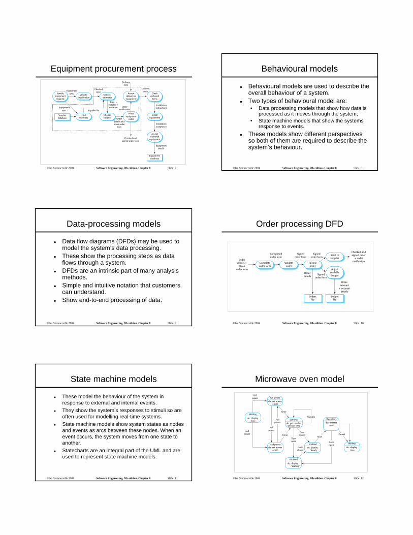
Data-processing models
Data flow diagrams (DFDs) may be used to model the system’s data processing.These show the processing steps as data flows through a system.DFDs are an intrinsic part of many analysis methods.Simple and intuitive notation that customers can understand.Show end-to-end processing of data.
©Ian Sommerville 2004 Software Engineering, 7th edition. Chapter 8 Slide 10
Order processing DFD
©Ian Sommerville 2004 Software Engineering, 7th edition. Chapter 8 Slide 11
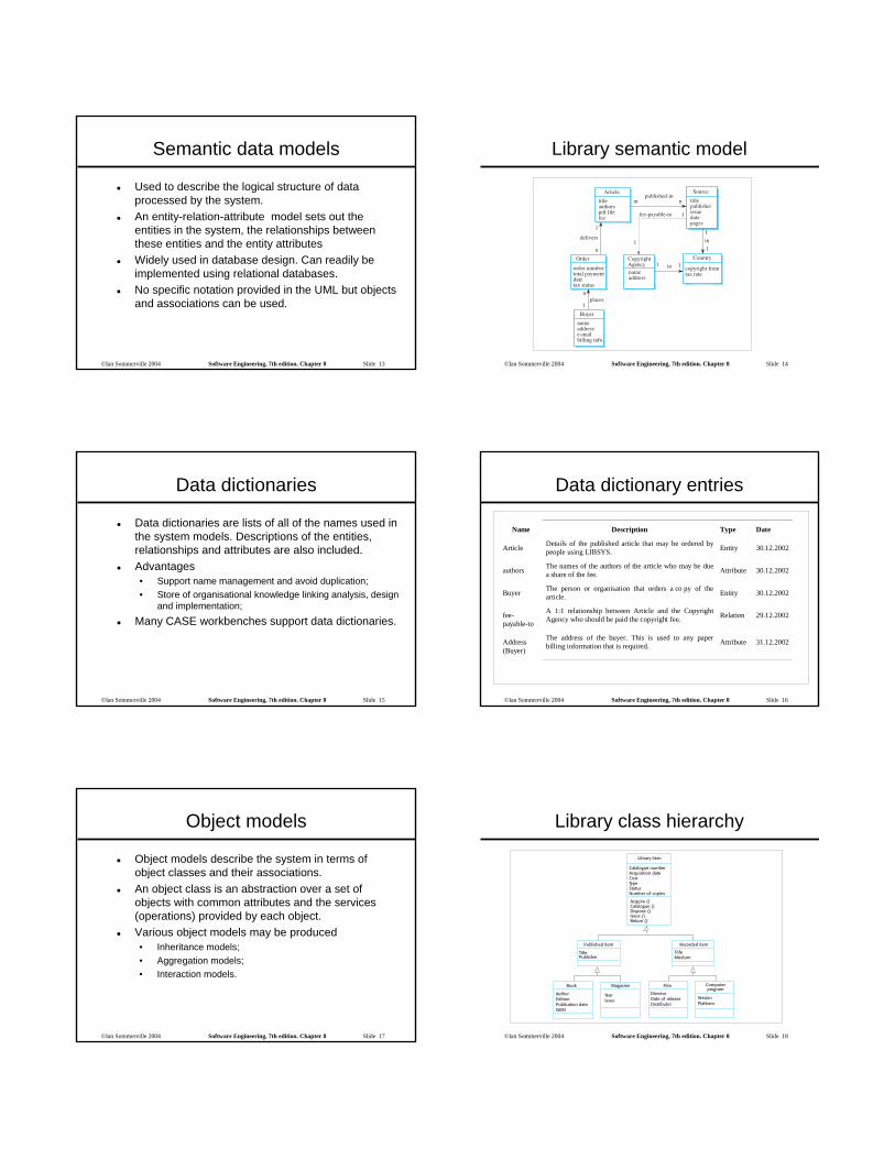
State machine models
These model the behaviour of the system in response to external and internal events.They show the system’s responses to stimuli so are often used for modelling real-time systems.State machine models show system states as nodes and events as arcs between these nodes. When an event occurs, the system moves from one state to another.Statecharts are an integral part of the UML and are used to represent state machine models.
©Ian Sommerville 2004 Software Engineering, 7th edition. Chapter 8 Slide 12
Microwave oven model
©Ian Sommerville 2004 Software Engineering, 7th edition. Chapter 8 Slide 13
Semantic data models
Used to describe the logical structure of data processed by the system.An entity-relation-attribute model sets out the entities in the system, the relationships between these entities and the entity attributesWidely used in database design. Can readily be implemented using relational databases.No specific notation provided in the UML but objects and associations can be used.
©Ian Sommerville 2004 Software Engineering, 7th edition. Chapter 8 Slide 14
Library semantic model
©Ian Sommerville 2004 Software Engineering, 7th edition. Chapter 8 Slide 15
Data dictionaries
Data dictionaries are lists of all of the names used in the system models. Descriptions of the entities, relationships and attributes are also included.Advantages• Support name management and avoid duplication;• Store of organisational knowledge linking analysis, design
and implementation;
Many CASE workbenches support data dictionaries.
©Ian Sommerville 2004 Software Engineering, 7th edition. Chapter 8 Slide 16
Data dictionary entries
Name Description Type Date
Article Details of the published article that may be ordered bypeople using LIBSYS. Entity 30.12.2002
authors The names of the authors of the article who may be duea share of the fee. Attribute 30.12.2002
Buyer The person or organisation that orders a co py of thearticle. Entity 30.12.2002
fee-payable-to
A 1:1 relationship between Article and the CopyrightAgency who should be paid the copyright fee. Relation 29.12.2002
Address(Buyer)
The address of the buyer. This is used to any paperbilling information that is required. Attribute 31.12.2002
©Ian Sommerville 2004 Software Engineering, 7th edition. Chapter 8 Slide 17
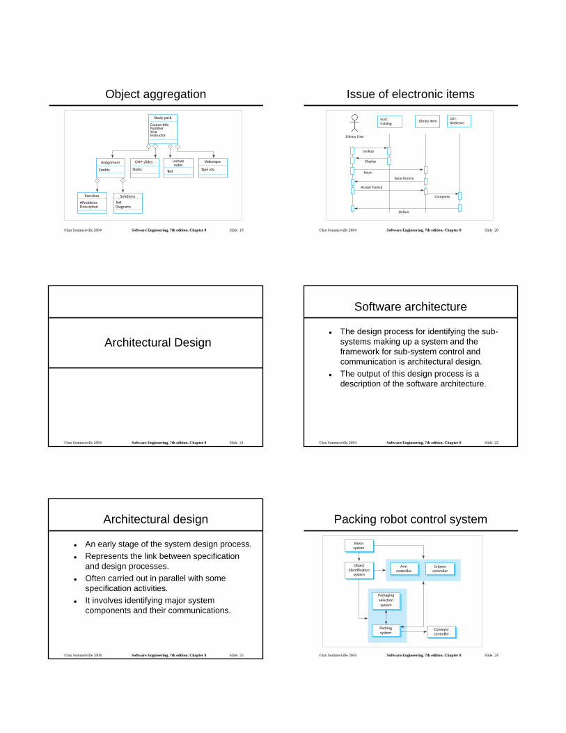
Object models
Object models describe the system in terms of object classes and their associations.An object class is an abstraction over a set of objects with common attributes and the services (operations) provided by each object.Various object models may be produced• Inheritance models;• Aggregation models;• Interaction models.
©Ian Sommerville 2004 Software Engineering, 7th edition. Chapter 8 Slide 18
Library class hierarchy
©Ian Sommerville 2004 Software Engineering, 7th edition. Chapter 8 Slide 19
Object aggregation
©Ian Sommerville 2004 Software Engineering, 7th edition. Chapter 8 Slide 20
Issue of electronic items
©Ian Sommerville 2004 Software Engineering, 7th edition. Chapter 8 Slide 21
Architectural Design
©Ian Sommerville 2004 Software Engineering, 7th edition. Chapter 8 Slide 22
Software architecture
The design process for identifying the sub-systems making up a system and the framework for sub-system control and communication is architectural design.The output of this design process is a description of the software architecture.
©Ian Sommerville 2004 Software Engineering, 7th edition. Chapter 8 Slide 23
Architectural design
An early stage of the system design process.Represents the link between specification and design processes.Often carried out in parallel with some specification activities.It involves identifying major system components and their communications.
©Ian Sommerville 2004 Software Engineering, 7th edition. Chapter 8 Slide 24
Packing robot control system
©Ian Sommerville 2004 Software Engineering, 7th edition. Chapter 8 Slide 25
Architectural models
Used to document an architectural design.Static structural model that shows the major system components.Dynamic process model that shows the process structure of the system.Interface model that defines sub-system interfaces.Relationships model such as a data-flow model that shows sub-system relationships.Distribution model that shows how sub-systems are distributed across computers.
©Ian Sommerville 2004 Software Engineering, 7th edition. Chapter 8 Slide 26
The repository model
Sub-systems must exchange data. This may be done in two ways:• Shared data is held in a central database or
repository and may be accessed by all sub-systems;
• Each sub-system maintains its own database and passes data explicitly to other sub-systems.
When large amounts of data are to be shared, the repository model of sharing is most commonly used.
©Ian Sommerville 2004 Software Engineering, 7th edition. Chapter 8 Slide 27
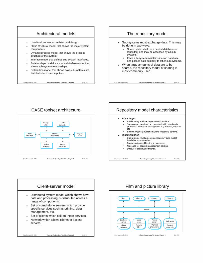
CASE toolset architecture
©Ian Sommerville 2004 Software Engineering, 7th edition. Chapter 8 Slide 28
Repository model characteristics
Advantages• Efficient way to share large amounts of data;• Sub-systems need not be concerned with how data is
produced Centralised management e.g. backup, security, etc.
• Sharing model is published as the repository schema.Disadvantages• Sub-systems must agree on a repository data model.
Inevitably a compromise;• Data evolution is difficult and expensive;• No scope for specific management policies;• Difficult to distribute efficiently.
©Ian Sommerville 2004 Software Engineering, 7th edition. Chapter 8 Slide 29
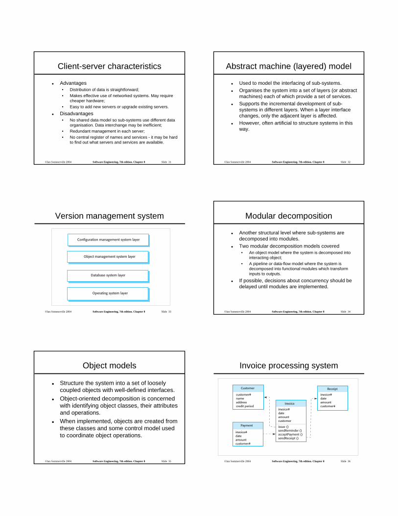
Client-server model
Distributed system model which shows how data and processing is distributed across a range of components.Set of stand-alone servers which provide specific services such as printing, data management, etc.Set of clients which call on these services.Network which allows clients to access servers.
©Ian Sommerville 2004 Software Engineering, 7th edition. Chapter 8 Slide 30
Film and picture library
©Ian Sommerville 2004 Software Engineering, 7th edition. Chapter 8 Slide 31
Client-server characteristics
Advantages• Distribution of data is straightforward;• Makes effective use of networked systems. May require
cheaper hardware;• Easy to add new servers or upgrade existing servers.
Disadvantages• No shared data model so sub-systems use different data
organisation. Data interchange may be inefficient;• Redundant management in each server;• No central register of names and services - it may be hard
to find out what servers and services are available.
©Ian Sommerville 2004 Software Engineering, 7th edition. Chapter 8 Slide 32
Abstract machine (layered) model
Used to model the interfacing of sub-systems.Organises the system into a set of layers (or abstract machines) each of which provide a set of services.Supports the incremental development of sub-systems in different layers. When a layer interface changes, only the adjacent layer is affected.However, often artificial to structure systems in this way.
©Ian Sommerville 2004 Software Engineering, 7th edition. Chapter 8 Slide 33
Version management system
©Ian Sommerville 2004 Software Engineering, 7th edition. Chapter 8 Slide 34
Modular decomposition
Another structural level where sub-systems are decomposed into modules.Two modular decomposition models covered• An object model where the system is decomposed into
interacting object;• A pipeline or data-flow model where the system is
decomposed into functional modules which transform inputs to outputs.
If possible, decisions about concurrency should be delayed until modules are implemented.
©Ian Sommerville 2004 Software Engineering, 7th edition. Chapter 8 Slide 35
Object models
Structure the system into a set of loosely coupled objects with well-defined interfaces.Object-oriented decomposition is concerned with identifying object classes, their attributes and operations.When implemented, objects are created from these classes and some control model used to coordinate object operations.
©Ian Sommerville 2004 Software Engineering, 7th edition. Chapter 8 Slide 36
Invoice processing system

©Ian Sommerville 2004 Software Engineering, 7th edition. Chapter 8 Slide 37
Object model advantages
Objects are loosely coupled so their implementation can be modified without affecting other objects.The objects may reflect real-world entities.OO implementation languages are widely used.However, object interface changes may cause problems and complex entities may be hard to represent as objects.
©Ian Sommerville 2004 Software Engineering, 7th edition. Chapter 8 Slide 38
Function-oriented pipelining
Functional transformations process their inputs to produce outputs.May be referred to as a pipe and filter model (as in UNIX shell).Variants of this approach are very common. When transformations are sequential, this is a batch sequential model which is extensively used in data processing systems.Not really suitable for interactive systems.
©Ian Sommerville 2004 Software Engineering, 7th edition. Chapter 8 Slide 39
Invoice processing system
©Ian Sommerville 2004 Software Engineering, 7th edition. Chapter 8 Slide 40
Pipeline model advantages
Supports transformation reuse.Intuitive organisation for stakeholder communication.Easy to add new transformations.Relatively simple to implement as either a concurrent or sequential system.However, requires a common format for data transfer along the pipeline and difficult to support event-based interaction.
©Ian Sommerville 2004 Software Engineering, 7th edition. Chapter 8 Slide 41
Control styles
Are concerned with the control flow between sub-systems. Distinct from the system decomposition model.Centralised control• One sub-system has overall responsibility for
control and starts and stops other sub-systems.Event-based control• Each sub-system can respond to externally
generated events from other sub-systems or the system’s environment.
©Ian Sommerville 2004 Software Engineering, 7th edition. Chapter 8 Slide 42
Centralised control
A control sub-system takes responsibility for managing the execution of other sub-systems.Call-return model• Top-down subroutine model where control starts at the
top of a subroutine hierarchy and moves downwards. Applicable to sequential systems.
Manager model• Applicable to concurrent systems. One system
component controls the stopping, starting and coordination of other system processes. Can be implemented in sequential systems as a case statement.
©Ian Sommerville 2004 Software Engineering, 7th edition. Chapter 8 Slide 43
Call-return model
©Ian Sommerville 2004 Software Engineering, 7th edition. Chapter 8 Slide 44
Real-time system control
©Ian Sommerville 2004 Software Engineering, 7th edition. Chapter 8 Slide 45
Event-driven systems
Driven by externally generated events where the timing of the event is outwith the control of the sub-systems which process the event.Two principal event-driven models• Broadcast models. An event is broadcast to all sub-
systems. Any sub-system which can handle the event may do so;
• Interrupt-driven models. Used in real-time systems where interrupts are detected by an interrupt handler and passed to some other component for processing.
Other event driven models include spreadsheets and production systems.
©Ian Sommerville 2004 Software Engineering, 7th edition. Chapter 8 Slide 46
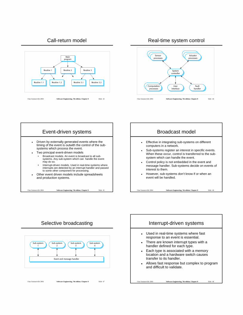
Broadcast model
Effective in integrating sub-systems on different computers in a network.Sub-systems register an interest in specific events. When these occur, control is transferred to the sub-system which can handle the event.Control policy is not embedded in the event and message handler. Sub-systems decide on events of interest to them.However, sub-systems don’t know if or when an event will be handled.
©Ian Sommerville 2004 Software Engineering, 7th edition. Chapter 8 Slide 47
Selective broadcasting
©Ian Sommerville 2004 Software Engineering, 7th edition. Chapter 8 Slide 48
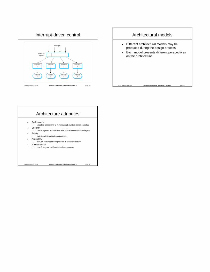
Interrupt-driven systems
Used in real-time systems where fast response to an event is essential.There are known interrupt types with a handler defined for each type.Each type is associated with a memory location and a hardware switch causes transfer to its handler.Allows fast response but complex to program and difficult to validate.
©Ian Sommerville 2004 Software Engineering, 7th edition. Chapter 8 Slide 49
Interrupt-driven control
©Ian Sommerville 2004 Software Engineering, 7th edition. Chapter 8 Slide 50
Architectural models
Different architectural models may be produced during the design processEach model presents different perspectives on the architecture
©Ian Sommerville 2004 Software Engineering, 7th edition. Chapter 8 Slide 51
Architecture attributes
Performance• Localise operations to minimise sub-system communication
Security• Use a layered architecture with critical assets in inner layers
Safety• Isolate safety-critical components
Availability• Include redundant components in the architecture
Maintainability• Use fine-grain, self-contained components