Embed Size (px)
Citation preview
cobas® 4800 SystemSystem ManualSoftware Version 2.1
cobas® 4800 System
Document information
Systeni Manual
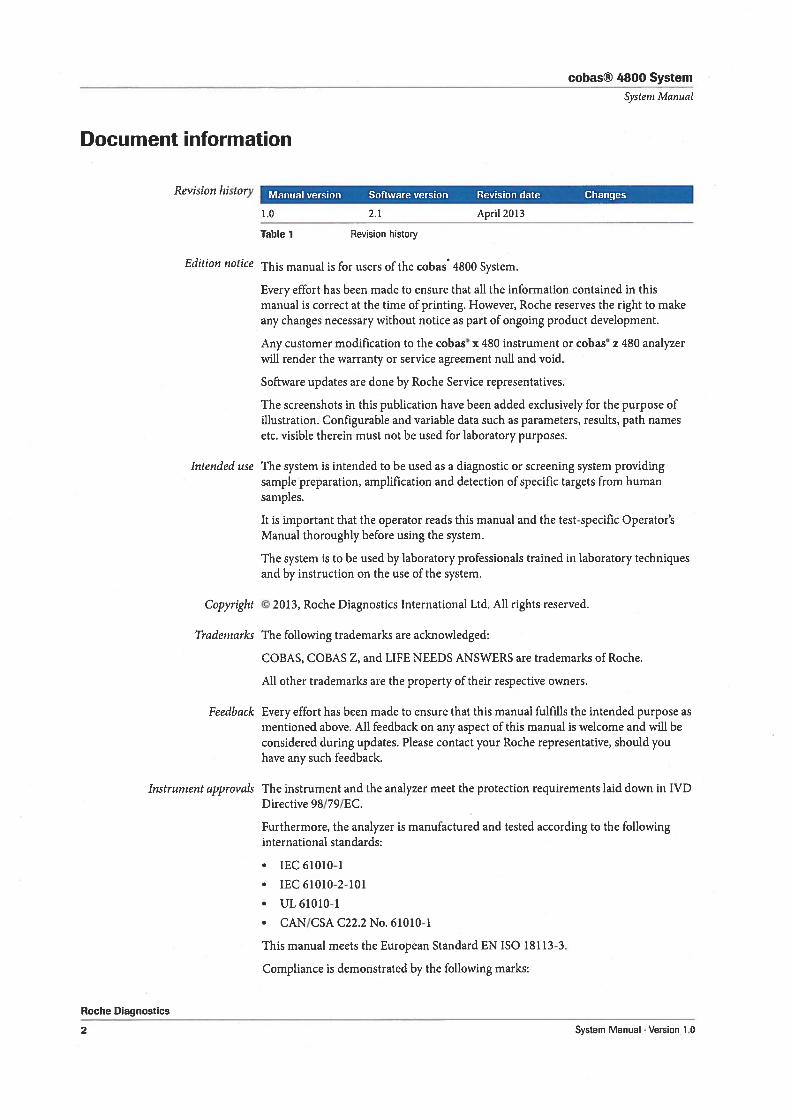
Revision history
Instrument approvals
Roche Diagnostics
2
Manual version Software version Revision date Changes
1.0 2.1 April2013
Table 1 Revsion history
Edition notice This manual is for users of the cobas 4800 System.
Every effort has been made to ensure that all the information contained in thismanual is correct at the time of printing. However, Roche reserves the right to makeany changes necessary without notice as part of ongoing product development.
Any customer modification to the cobas x 480 instrument or cobas z 480 analyzerwill render the warranty or service agreement null and void.
Software updates are done by Roche Service representatives.
The screenshots in this publication have been added exclusively for the purpose ofilustration. Configurable and variable data such as parameters, resuits, path namesetc. visible therein must not be used for laboratory purposes.
Intended use The system is intended to be used as a diagnostic or screening system providingsamplepreparation, amplification and detection of specific targets from humansamples.
It is important that the operator reads this manual and the test-specific Operator’sManual thoroughly before using the system.
The system is to be used by laboratory professionals trained in laboratory techniquesand by instruction on the use of the system.
Copyright © 2013, Roche Diagnostics International Ltd. All rights reserved.
Tradernarks The following trademarks are acknowledged:
COBAS, COBAS Z, and LIFE NEEDS ANSWERS are trademarks of Roche.
All other trademarks are the property of their respective owners.
Feedback Every effort has been made to ensure that this manual fulfills the intended purpose asmentioned above. All feedback on any aspect of this manual is welcome and will beconsidered during updates. Please contact your Roche representative, should youhave any such feedback.
The instrument and the analyzer meet the protection requirements laid down in IVDDirective 98/79/EG.
Furthermore, the analyzer is manufactured and tested according to the followinginternational standards:
• lEG 61010-1
• lEG 61010-2-101
• UL61O1O-1
• CAN/CSA C22.2 No. 61010-1
This manual meets the European Standard EN ISO 18113-3.
Compliance is demonstrated by the following marks:
System Manual . Version 1.0
cobas® 4800 System
Systeni Manual
Contact addresses
Roche Diagnostics
System Manual . Version 1.0
C ( Complies with the IVD directive 98/79/EG.
Issued by underwriters laboratories, mc. (UL) for Canada and the US.
C®(JS
Roche Molecular Systems, mc.1080 U.S. Highway SouthBranchburg, NJ 08876- 1760USAMade in Switzerland
Roche Diagnostics GmbH1 ECIREPI SandhoferStrasse 11668305 MannheimGermany
3
cobas® 4800 System
System Manual
Roche Diagnostics
4 System Manual Version 1.0
cobas® 4800 System
Sys(em Iftinunl
Table of contents
Document informationContact addressesTable of contentsPrefaceHow to use this manualWhere to find informationConventions used in this manual
4 Software
Basic software elementsDatabase
Configuration
73
81
5 Configuration
Configuration 87User management 92Exporting support data 97Result counters 98
Maintenance
6 Maintenance
Safety informationInstrument maintenanceAnalvzer maintenance
Roche Diagnostics
System Manual . Version 1.0
103104
115
Troubleshooting7
357
777
System description
7 Troubleshooting
Overview 129Messages work area 131About result flags 134General troubleshooting 136Hardware troubleshooting 138
Glossary
8 Glossary
Index
Index 149
Revisions
1 General safety information
Safety classificationsSafety precautionsSafety summarySafety labels on the systemDisposal
2 Overview
System overview
3 Hardware
InstrumentAnalyzerControl unit
1516182527
31
396569
5
cobas® 4800 System
System I’4anual
Roche Diagnostics
System Manual Version 1.06
cobas® 4800 System
Systeni Manual
Preface
The system integrates fully automated total nucleic acid isolation directly fromprimary and secondary tubes, automated PCR setup, and real time PCR.
This manual covers the complete system comprised of the cobas’ 4800 software, theinstrument used for sample preparation, and the analyzer used for amplification anddetection using real time PCR.
How to use this manual
• Keep this manual in a safe place to ensure that t is not damaged and remains available
for use.
• This manual should be easily accessible at all times.
To help you find information quickly, there is a table of contents at the beginning ofthe manual and each chapter. In addition, a complete index can be found at the endof the manual.
Where to find information
In addition to this manual, the following documents are also provided to assist infinding desired information quickly:
Test-specfic Operator Manuals For each test, there is a specific Operator’s Manual which describes how to prepareand perform a run, and how to handle results.
Test-specficpackage insert For each test, there is a package insert which provides additional information. Forexample, instructions on storage and handling of reagents, samples and controls.
Conventions used in this manual
Visual cues are used to help locate and interpret information in this manual quickly.This section explains formatting conventions used in this manual.
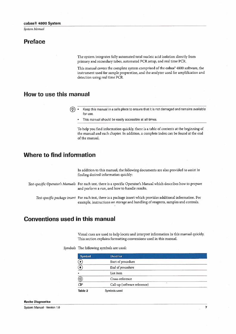
Symbols The following symbols are used:
Symbol Used for
( Start of procedure
End of procedure
List item
(j) Cross-reference
C’ Cail-up (software reference)
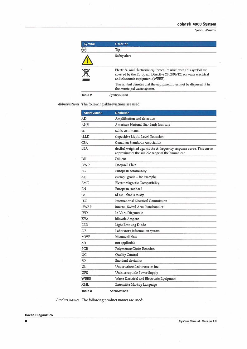
Table 2 Symbols used
Roche Diagnostics
System Manual Version 1.0 7
cobas® 4800 System
Systern Manual
Symbol Used for
J Tip
j/’ Safety alert
‘.‘ Electrical and electronic equipment marked with this symbol are/Y\ covered by the European Directive 2002/961EC on waste electrical
and electronic equipment (WEEE).
The symbol denotes that the equipment must not be disposed of inthe municipal waste system.
Table 2 Symbols used
Abbreviations The following abbreviations are used:
Abbreviation Definition
AD Amplification and detection
ANSI American National Standards Institute
cc cubic centimeter
cLLD Capacitive Liquid Level Detection
CSA Canadian Standards Association
dBA decibel weighted against the A-frequency response curve. This curveapproximates the audible range of the human ear.
DIL Diluent
DWP Deepweil Plate
EC European community
e.g. exempli gratia — for example
EMC ElectroMagnetic Compatibility
EN European standard
ie. id est — that is to say
IEC International Electrical Commission
iSWAP internal Swivel Arm Plate handler
IVD In Vitro Diagnostic
KVA kilovolt-Ampere
LED Light Emitting Diode
LIS Laboratory information system
MWP Microweli plate
n/a not applicable
PCR Polymerase Chain Reaction
QC Quality Control
SD Standard deviation
UL Underwriters Laboratories mc.
UPS Uninterruptible Power Supply
WEEE Waste Electrical and Electronic Equipment
XML Extensible Markup Language
Table 3 Abbreviations
Roche Diagnostics
8
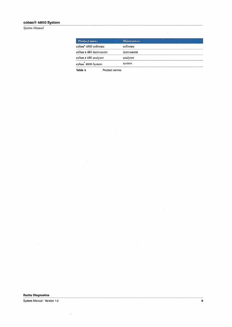
Product narnes The following product names are used:
System Manual . Version 1.0
cobas® 4800 System
Systern Manual
Roche Diagnostics
System Manual . Version 1.0
Product name Abbreviation
cobas 4800 software software
cobas x 480 instrument instrument
cobas z 480 analyzer analyzer
cobas 4800 System system
Tahie 4 Product nam es
9
cobas® 4800 System
Systeni Manual
Roche Diagnosti
System Manual Version 1.010
System description
1 General safety information 13
2 Overview 29
3 Hardware 37
4 Software 71

cobas® 4800 System 1 General safety information
Table of contents Systern Manual
General safety information
In this chapter, you will find information on the safe operation of the system.
In this chapter Chapter
Safety classifications 15
Safety precautions 16
Operator qualification 16
Safe and proper use of the system 16
Miscellaneous safety precautions 17
Safety summary 18
Warning messages 18
Electrical safety 18
Optical safety 18
Biohazardous materials 19
Waste 19
Explosion and fire risk 20
Caution messages 20
Mechanical safety 20
Reagents and consumables 21
Interfering substances in samples 21
Evaporation of samples or reagents 21
Incorrect resuits due to two barcode labels or incorrect specimen labeling....22
Incorrect resuits due to wrongly typed sample IDs 22
Carryover 22
Hot surfaces 22
Malfunction due to interfering electromagnetic fields 22
Data security 23
Notices 23
Movingparts 23
Circuit breakers and fuses 24
Spilage 24
Safety labels on the system 25
Safety labels on the instrument 25
Safety labels on the analyzer 26
Roche Diagnostics
System Manual . Verson 1.0 13
1 General safety information cobas® 4800 System
Table of contents System Manual
Disposal 27
Disposal of the instrument 27
Disposal of the analyzer 27
Disposal of control unit components 27
Roche fliagnostics
14 System Manual . Version 1.0
cobas® 4800 System 1 General safety information
Systern Manual Safety c1assfications
Safety classifications
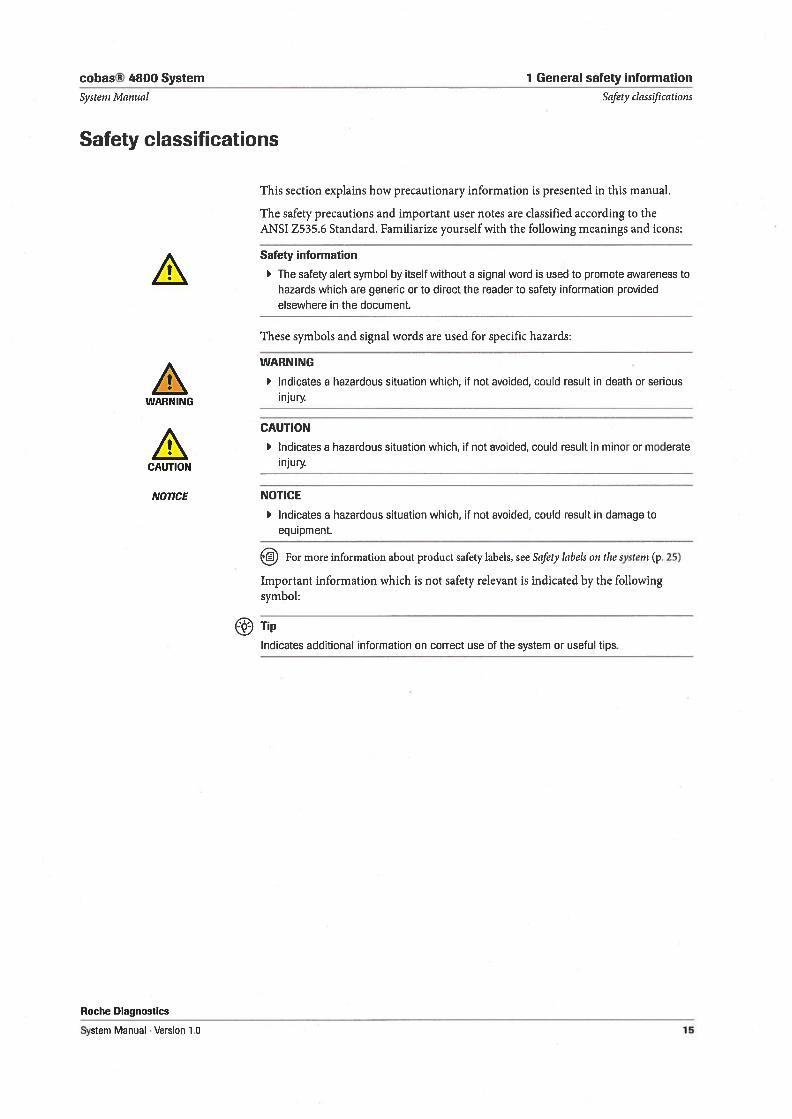
This section explains how precautionary information is presented in this manual.
The safety precautions and important user notes are classified according to theANSI Z535.6 Standard. Famiiarize yourselfwith the following meanings and icons:
Safety information
The safety alert symbol by itself without a signal word is used to promote awareness tohazards which are generic or to direct the reader to safety information providedelsewhere in the document.
These symbols and signal words are used for specific hazards:
WARNING
1 Indicates a hazardous situation which, if not avoided, could result in death or serious
WARNING Injury.
CAUTION
Indicates a hazardous situation which, if not avoided, could result in minor or moderate
CAUTION injury
NOTICE NOTICE
lndicates a hazardous situation which, if not avoided, could result in damage toequipment.
For more information about product safety labels, see Safety labels on the systern (p. 25)
Important information which is not safety relevant is indicated by the followingsymbol:
Tip
Indicates additional information on correct use of the system or useful tips.
Roche Diagnostics
System Manual . Version 1.0 15
1 General safety information cobas® 4800 System
Safetyprecautions System Manual
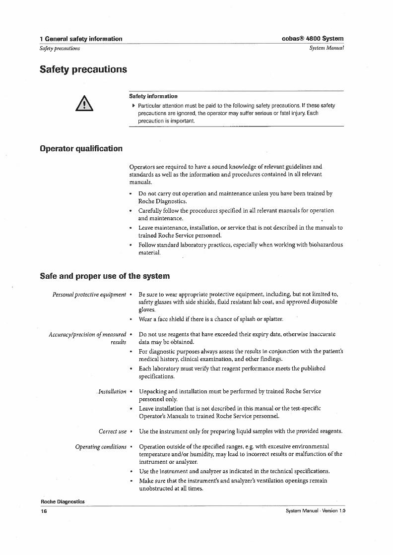
Safety precautions
Safety information
Particular attention must be paid to the following safety precautions. 1f these safety
precautions are ignored, the operator may suffer serious or fatal injury. Each
precaution is important.
Operator qualification
Operators are required to have a sound knowledge of relevant guidelines andstandards as well as the information and procedures contained in all relevantmanuals.
• Do not carry out operation and maintenance unless you have been trained byRoche Diagnostics.
• Carefully follow the procedures specified in all relevant manuals for operationand maintenance.
• Leave maintenance, installation, or service that is not described in the manuals totrained Roche Service personnel.
• Follow standard laboratory practices, especially when working with biohazardousmaterial.
Safe and proper use of the system
Personal protective equipnient • Be sure to wear appropriate protective equipment, including, but not limited to,safety glasses with side shields, fluid resistant lab coat, and approved disposablegloves.
• Wear a face shield ifthere is a chance of splash or splatter.
Accuracy/precision of measured • Do not use reagents that have exceeded their expiry date, otherwise inaccurateresults data may be obtained.
• For diagnostic purposes always assess the resuits in conjunction with the patient’smedical history, clinical examination, and other findings.
• Each laboratory must verify that reagent performance meets the publishedspecifications.
.Installation • Unpacking and installation must be performed by trained Roche Servicepersonnel only.
• Leave installation that is not described in this manual or the test-specificOperator’s Manuals to trained Roche Service personnel.
Correct use • Use the instrument only for preparing liquid samples with the provided reagents.
Operating conditions • Operation outside of the specified ranges, e.g. with excessive environmentaltemperature and/or humidity, may lead to incorrect resuits or malfunction of theinstrument or analyzer.
• Use the instrument and analyzer as indicated in the technical specifications.
• Make sure that the instrument’s and analyzer’s ventilation openings remainunobstructed at all times.
Roche Diagnostics
16 System Manual . Version 1.0
cobas® 4800 System 1 General safety information
Systern Manual Safetyprecautions
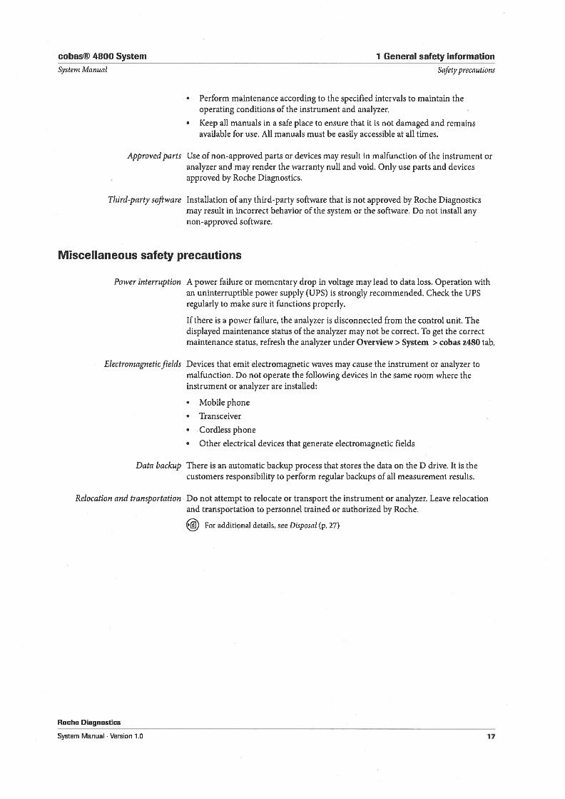
• Perform maintenance according to the specified intervals to maintain theoperating conditions of the instrument and analyzer.
• Keep all manuals in a safe place to ensure that it is not damaged and remainsavailable for use. All manuals must be easily accessible at all times.
Approvedparts Use of non-approved parts or devices may result in malfunction of the instrument oranalyzer and may render the warranty nuli and void. Only use parts and devicesapproved by Roche Diagnostics.
Third-party software Installation of any third-party software that is not approved by Roche Diagnosticsmay result in incorrect behavior of the system or the software. Do not instali anynon-approved software.
Miscellaneous safety precautions
Power interruption A power failure or momentary drop in voltage may lead to data loss. Operation withan uninterruptible power supply (UPS) is strongly recommended. Check the UPSregularly to make sure it functions properly.
1f there is a power failure, the analyzer is disconnected from the control unit. Thedisplayed maintenance status of the analyzer may not be correct. To get the correctmaintenance status, refresh the analyzer under Overview> System > cobas z480 tab.
Electrornagneticfields Devices that emit electromagnetic waves may cause the instrument or analyzer tomalfunction. Do not operate the following devices in the same room where theinstrument or analyzer are installed:
• Mobile phone
• Transceiver
• Cordless phone
• Other electrical devices that generate electromagnetic fields
Data backup There is an automatic backup process that stores the data on the D drive. It is thecustomers responsibility to perform regular backups of all measurement results.
Relocation and transportation Do not attempt to relocate or transport the instrument or analyzer. Leave relocationand transportation to personnel trained or authorized by Roche.
For additional details, see Disposal (p. 27)
Roche Diagnostics
System Manual . Version 1.0 17
1 General safety information cobas® 4800 System
Safety surnmay Systeni Aianual
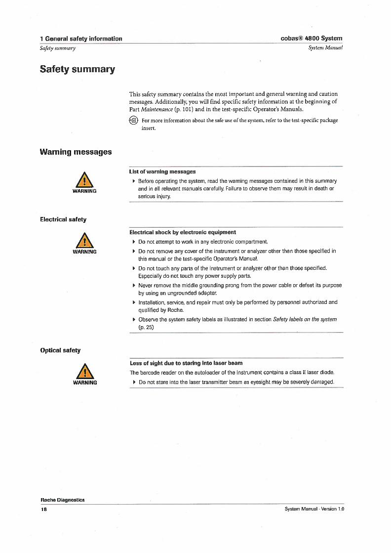
Safety summary
This safety summary contains the most important and general warning and cautionmessages. Additionally, you will find specific safety information at the beginning ofPart Ivfaintenance (p. 101) and in the test-specific Operator’s Manuals.
For more information about the safe use of the system, refer to the test-specific packageinsert.
Warning messages
List of warning messages
Before operating the system, read the warning messages contained in this summary
WARNING and in all relevant manuals carefully. Failure to observe them may result in death or
serious injury
Electrical safety
Electrical shock by electronic equipment
Do not attempt to work in any electronic compartment.
WARNING Do not remove any cover of the instrument or analyzer other than those specified in
this manual or the test-specific Operators Manual.
Do not touch any parts of the instrument or analyzer other than those specified.
Especially do not touch any power supply parts.
Never remove the middle grounding prong from the power cable or defeat its purpose
by using an ungrounded adapter.
Installation, service, and repair must only be performed by personnel authorized and
qualified by Roche.
Observe the system safety labels as illustrated in section Safety labels on the system
(p25)
Optical safety
Loss of sight due to stanng into laser beam
The barcode reader on the autoloader of the instrument contains a class II laser diode.
WARNING Do not stare into the laser transmitter beam as eyesight may be severely damaged.
Roche Diagnostics
18 System Manual Version 1.0
cobas® 4800 System 1 General safety information
System j’vlanual Safrty summary
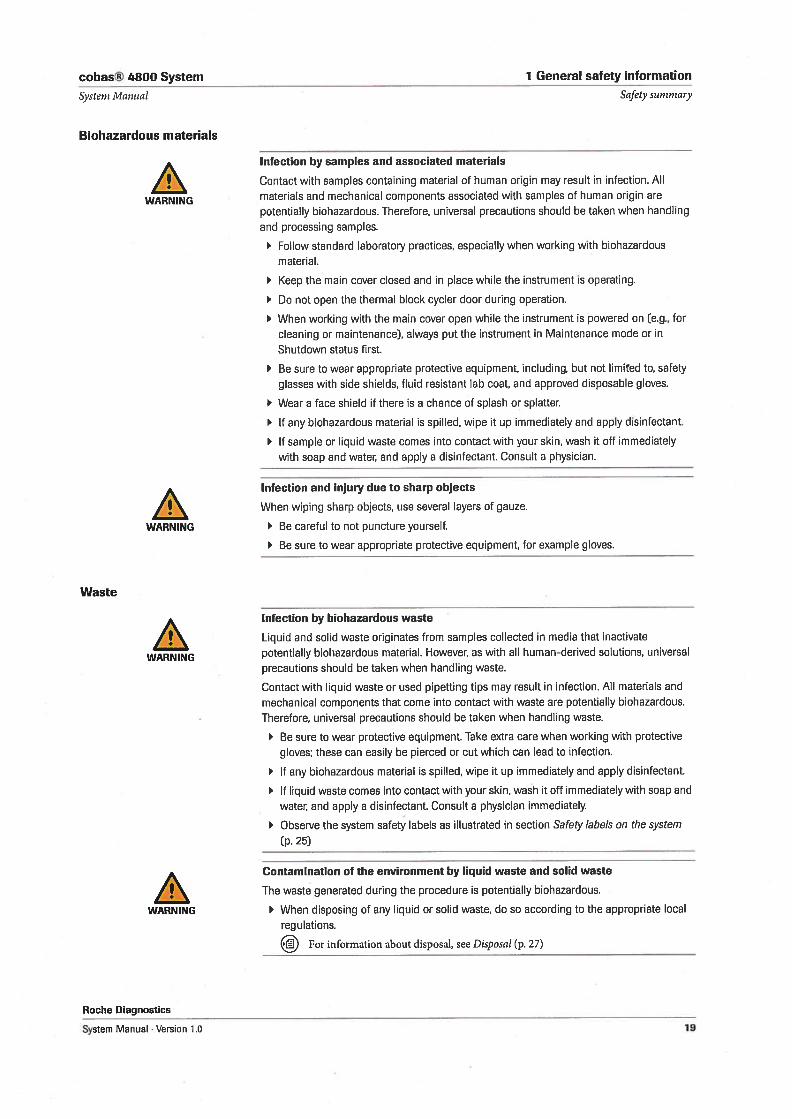
Biohazardous materials
Infection by samples and associated matenals
Contact with samples containing material of human origin may result in infection. All
WARNING materials and mechanical components associated with samples of human origin are
potentially biohazardous. Therefore, universal precautions should be taken when handling
and processing samples.
Follow standard laboratory practices, especially when working with biohazardous
material.
Keep the main cover closed and in place while the instrument is operating.
Do not open the thermal block cycler door during operation.
When working with the main cover open while the instrument is powered on (eg., for
cleaning or maintenancej, always put the instrument in Maintenance mode or in
Shutdown status first.
Be sure to wear appropriate protective equipment, including, but not limited to, safety
glasses with side shields, fluid resistant lab coat, and approved disposable gloves.
Wear a face shield if there is a chance of splash or splatter.
1f any biohazardous material is spilled, wipe it up immediately and apply disinfectant.
It sample or liquid waste comes into contact with your skin, wash it oft immediately
with soap and water, and apply a disinfectant. Consult a physician.
Infection and injury due to sharp objects
When wiping sharp objects, use several layers of gauze.
WARNING Be careful to not puncture yourself.
Be sure to wear appropriate protective equipment, for example gloves.
Waste
Infection by biohazardous waste
Liquid and solid waste originates from samples collected in media that inactivate
WARNING potentially biohazardous material. However, as with all human-derived solutions, universal
precautions should be taken when handling waste.
Contact with liquid waste or used pipetting tips may result in infection. All materials and
mechanical components that come into contact with waste are potentially biohazardous.
Therefore, universal precautions should be taken when handling waste.
Be sure to wear protective equipment. Take extra care when working with protective
gloves; these can easily be pierced or cut which can lead to infection.
1f any biohazardous material is spilled, wipe t up immediately and apply disinfectant.
1f liquid waste comes into contact with your skin, wash it off immediately with soap and
water, and apply a disinfectant. Consult a physician immediately
Observe the system safety labels as illustrated in section Safety labels on the system
(p.25)
Contamination of the environment by liquid waste and solid waste
The waste generated during the procedure is potentially biohazardous.
WARNING When disposing of any Jiquid or solid waste, do so according to the appropriate local
regulations.
For information about disposal, see Disposal (p. 27)
Roche Diagnostics
System Manual Version 1.0 19
1 General safety information cobas® 4800 System
Safety surnniary Systeni Manual
Explosion and fire risk
Explosion through sparks
Hazard of explosion through sparks.
WARNING Keep all potentially flammable or explosive material (eg. anesthetic gas) away from the
instrument or analyzer.
Fire risk through usage of sprays
Spraying liquid on the power supply paas can cause a sho circuit and result in a fire.
WARNING During fire-fighting operations disconnect the equipment from the main power supply.
Keep the cover closed while the instrument and analyzer is connected to the main
power supply, and do not use sprays in the vicinity of the instrument and analyzer.
Caution messages
List of caution messages
Before operating the system, read the caution messages contained in this summa
CAUTION and in all relevant manuals carefully. Failure to observe them may result in minor or
moderate injury.
Mechanical safety
Personal injury due to contact with moving parts
The pipetting head of the instrument moves rapidly during sample preparation. The main
CAUTION cover is locked during operation, protecting the user from moving parts.
Keep the main cover closed and in place while the instrument is operating.
When working with the main cover open while the instrument is powered on (eg., for
cleaning or maintenance), always put the instrument in Maintenance mode or in
Shutdown status first.
Do not touch any parts of the instrument or analyzer other than these specified. Keep
away from moving parts during instrument operation.
Do not remove any carrier from the instrument deck while the instrument is operating.
Keep the main cover closed and in place while the instrument is operating.
During operation and maintenance of the instrument, proceed according to the
instructions.
Observe the system safety labels as illustrated in section Safety labels on the system(p. 25)
Roche Diagnostics
20 System Manual Version 1.0
cobas® 4800 System 1 General safety information
System Aianual Safety suniniary
Reagents and consumables
Skin infiammation or injury caused by reagents
Direct contact with reagents, detergents, or cleaning solutions may cause skin irritation,
CAUTION inflammation, or burns.
When handling reagents, exercise the precautions required for handling laboratory
reagents. Be sure to wear protective equipment (such as goggies, gloves).
Observe the cautions given in the package insert and observe the information given in
the Material Safety Data Sheets available for Roche Diagnostics reagents and cleaning
solutions.
b 1f a reagent or detergent comes into contact with your skin, wash t off immediately
with soap and water, and apply a disinfectant. Consult a physician immediately
Invalid results due to incorrect reagent volume
Incorrect reagent handling may cause an undetectable loss of reagent.
CAUTION Store reagents always according to specified storage conditions.
Do not leave opened sample containers on the system for any considerable Iength of
time to avoid evaporation.
Avoid creating foam 0fl top of reagents in filled reagent reservoirs and in reagent vials
that are placed on reagent carriers.
Partially used reagents should not be used on other cobas® 4800 systems.
Invalid results due to expired reagents and consumables
Data obtained using expired reagents and consumables are not reliable. Reagents are
CAUTION supplied in a kit package with a label that indicates the expiry date. The expiry date of
microwell plate and sealing film is printed on their package label.
Do not use reagents and consumables that have exceeded their expiry dates. Replace
expired reagents and consumables with unexpired reagents and consumables before
sample processing.
Choosing the wrong test kit
Make sure to choose the correct test kit for the required test. Choosing a wrong test kit
CAUTION will not let you proceed with the test.
Interfering substances in samples
Invalid resuits due to interfering substances
lnterfering substances in samples may cause clogging and lead to incorrect results.
CAUTION
Evaporation of samples or reagents
Pipetting errors due to evaporation of samples or reagents
Evaporation of samples or reagents may lead to pipetting errors.
CAUTION Do not leave opened sample containers on the system for any considerable length of
time.
For additional details, refer to test-specific package insert.
Processing of the samples must commence within specified time after reagent
barcodes have been scanned as indicated in the software.
Do not use expired reagents.
Roche Diagnostics
System Manual Version 1.0 21
1 General safety information cobas® 4800 System
Safety sunimary Systeni Ivianual
Incorrect resuits due to two barcode labels or incorrect specimen labeling
Incorrect resuits due to two barcodes on the same tube or mixing up specimenbarcodes
CAUTION Duplicate barcodes are not accepted on the system within the same run.
Take adequate measures to avoid placing incorrect barcode on specimen.
Make sure that there is only one barcode on each specimen tube.
Incorrect resuits due to wrongly typed sample lOs
Incorrect resuits due to incorrect sample IDs
1f the sample IDs are entered manually, there is the risk of making spelling mistakes or
CAUTION entering wrong sample IDs.
After printing the microwell plate layout, compare the sample IDs on the tubes with thesample IDs on the microwell plate Iayout.
1f you notice a mistake, correct the mistake in the sample ID column. Then save the
work order file and use the new printout for setting up the microwell plate.
Carryover
Incorrect resuits due to carryover
Traces of analytes or reagents may be carried over from one test to the next.
Take adequate measures to prevent carryover and to avoid potentially false results.
When any indication of potential sources of contamiriation is seen (e.g. puncturedsealing film, spilled reagents or samples, etc.), or if manual sample preparation was notperformed according to good laboratory practice, proper decontamination procedures
must be performed.
Hot surfaces
Personal injury due to hot surface
The heater/shaker cradle on the instrument and the microwell plate holder, the thermalblock cycler, the block cycler cover, and the Xenon lamp on the analyzer are hot whileoperating.
Do not touch hot surfaces.
Malfunction due to interfering electromagnetic fields
Malfunction of system and incorrect results due to interfering electromagneticfields
Devices that emit electromagnetic waves may cause the analyzer to malfunction.
The electromagnetic environment should be evaluated prior to operation of the device.
Do not operate this system in close proximity to sources of strong electromagneticfields (for example unshielded intentional RF sources), as they may interfere withproper operations.
Roche Diagnostics
22 System Manual . Version 1.0
cobas® 4800 System 1 General safety information
Systeni Manual Safety sunirnary
Data security
Unauthorized access and data loss due to malicious software and hacker attacks
Portable storage media can be infected with and transmit computer malware, which may
CAUTION be used to gain unauthorized access to data or cause unwanted changes to software.
The system is not protected against malicious software and hacker attacks.
The customers are responsible for IT security of their IT infrastructure and for protecting it
against malicious software and hacker attacks. Failure to do so may result in data loss or
render the system unusable.
Roche recommends the following precautions:
Allow connection to authorized external devices only
Ensure that all external devices are protected by appropriate security software.
Ensure that access to all external devices is protected by appropriate security
equipment. cobas IT firewall must be used when the system is integrated into a
network.
Do not copy or install any software on the software control unit unless it is part of the
system software or you are nstructed to do so by a Roche Service representative.
It additional software is required, contact your Roche Service representative to ensure
validation of the software in question.
Do not use the USB ports to connect other storage devices unless you are instructed to
do so by official user documentation or a Roche Service representative.
Exercise utmost care when using external storage devices such as USB flash drives,
CDs, or DVDs. Do not use them on public or home computers while connecting to the
system.
Keep all external storage devices in a secure place and ensure that they can be
accessed by authorized persons only
Do not enter any confidential patient-relevant information into the work order file.
There is the risk of unauthorized access to patient data.
Notices
NOTICE List of notices
Before operating the system, read the notices contained in this summary carefully Failure
to observe them may result in damage to equipment.
Moving parts
Damage to the instrument due to contact with moving parts
Contact with moving parts may damage some components.
Keep all covers closed and in place while the instrument is operating.
Do not touch any parts of the instrument other than those specified. Keep away from
moving parts during instrument operation.
Hoche Diagnostics
System Manual . Version 1.0 23
1 General safety information cobas® 4800 System
Safety suniniary System Manual
Circuit breakers and fuses
Damage to the instrument or analyzer due to improper use
Should one of the instrument er analyzer circuit breakers or fuses blow, do not attempt tooperate the instrument or analyzer before contacting either your Roche Servicerepresentative or technical support.
Spillage
Malfunction due to spilled liquid
Any liquid spilled on the instrument or analyzer may result in malfunction, or damage ofthe instrument or analyzer.
Do not place samples, reagents, or any other liquid on the surface of the instrument oranalyzer other than in designated areas.
Do not place the microweli plate on any part of analyzer other than the microweli plateloader.
1f liquid does spul on the instrument or analyzer, wipe t up immediately and applydisinfectant. Be sure to wear protective equipment.
Roche Diagnostics
24 System Manual . Version 1.0
cobas® 4800 System 1 General safety information
Systeni Manual
Safety labels on the system
Safety labels on the system
Warning labels draw your attention to areas of potential hazard. The labels and theirdefinitions are listed below according to their location.
The safety labels comply with the following standards: ANSI Z535.6, EN 15223-1,IEC 61010-1, or ISO 7000.
1f the labels are damaged, they must be replaced by Roche Service personnel. For
replacement labels, contact your local Roche representative.
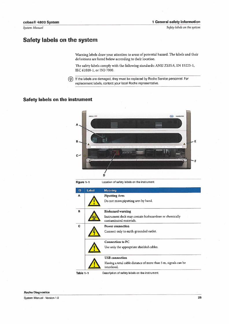
Safety labels on the instrument
A Pipetting Arm
Do not move pipetting arm by hand.
B Biohazard warning
14r),, Instrument deck may contain biohazardous or chemicallycontaminated materials.
C Power connection
Connect only to earth-grounded outlet.
Connection to PC
Use only the appropriate shielded cables.
USB connection
Having a total cable distance of more than 5 m, signals can beinterfered.
Table 1-1 Description of safety labels on the instrument
Roche Diagnostics
Figure 1-1 Location of safety labels on the instrument
ID Label Meaning
System Manual . Version 1.0 25
1 General safety information cobas® 4800 System
Safety labels on the system Systeni .lv.tanual
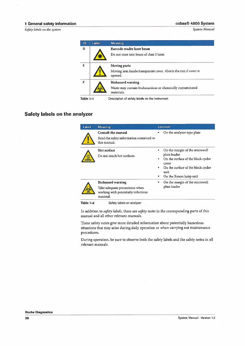
ID Label Meaning
13 Barcode reader laser beam
Do not stare into beam of class 2 laser.
E Moving parts
Moving arm inside transparent cover. Aborts the run if cover isopened.
F Biohazard warning
,(ç).. Waste may contain biohazardous or chemically contaminatedmaterials.
Table 1-1 Description of safety labels on the instrument
Safety labels on the analyzer
Label Meaning Location
Consult the manual • On the analyzer type plate
Read the safety information contained inthis manual.
Hot surface • On the margin of the microweil
, Do not touch hot surfaces. plate loader• On the surface of the block cycler
cover• On the surface of the block cycler
unit• On the Xenon lamp unit,\ Biohazard warning • On the margin of the microweil
— Take adequate precautions when plate loader
working with potentially infectiousmaterial.
Table 1-2 Safety labels on analyzer
In addition to safety labels, there are safrty notes in the corresponding parts of thismanual and all other relevant manuals.
These safety notes give more detailed information about potentially hazardoussituations that may arise during daily operation or when carrying out maintenanceprocedures.
During operation, be sure to observe both the safety labels and the safety notes in allrelevant manuals.
Roche Diagnostics
26 System Manual . Version 1.0
cobas® 4800 System 1 General safety information
Systern Manual Disposal
Disposal
Disposal of the instrument
lnfection by a potentially biohazardous instrument
The instrument must be treated as potentially biohazardous waste. Decontamination (ie., a
WARNING combination of processes inciuding cleaning and disinfection) is required before reuse,recycling, or disposal of the instrument.
1f you want to dispose of the instrument, contact your Roche representative.
Disposal of the analyzer
Infection by a potentially biohazardous analyzer
The analyzer must be treated as potentially biohazardous waste. Decontamination (ie., a
WARNING combination of processes inciuding cleaning and disinfection) is required before reuse,recycling, or disposal of the analyzer.
1f you want to dispose of the analyzer, contact your Roche representative.
Disposal of control unit components
Disposal of control unit components
Components of your control unit (such as the computer, monitor, keyboard) which are
marked with this symbol are covered by the European Directive on Waste E/ectr/ca/ andElectronic Equipment C,VEEE, 2002/96/EC).
These items must be disposed of via designated collection facilities.
For more information about disposal of your old product, please contact your city office,waste disposal service or your Roche representative.
Constraint: It is left to the responsible laboratory organization to determine whether controlunit components are contaminated or not. 1f contaminated, treat them in the same way as
the instrument and analyzer.
Roche Diagnostics
System Manual Version 1.0 27
1 General safety information cobas® 4800 System
Disposal Systeni Mamal
Roche Diagnostics.
28 System Manual Version 1.0
cobas® 4800 System 2 Overview
Table of contents Systeni Alanual
Overview
In this chapter you get a basic overview about the whole system inciuding theinstrument, the analyzer, and the software.
In this chapter Chapter
System overview 31
Instrument 32
Analyzer 33
System software and control unit 34
LIS 34
Consumables 35
Roche Diagnostics
System Maniial Version 1.0 29
2 Overview cobas® 4800 System
Table of contents Systern Manual
Roche Diagnostics
ao System Manual Version 1.0
cobas® 4800 System 2 Overview
Systern Manual Systern overview
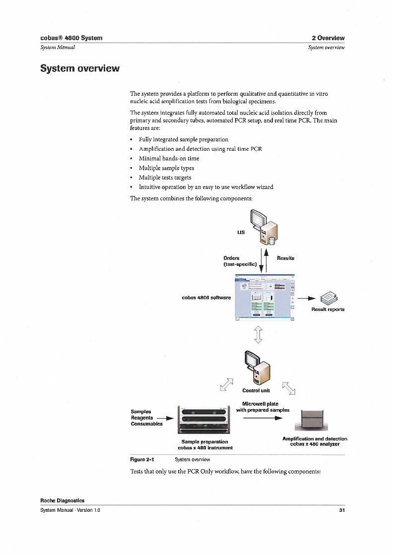
System overview
The system provides a platform to perform qualitative and quantitative in vitronucleic acid amplification tests from biological specimens.
The system integrates fully automated total nucleic acid isolation directly fromprimary and secondary tubes, automated PCR setup, and real time PCR. The mainfeatures are:
• Fully integrated sample preparation
• Amplification and detection using real time PCR
• Minimal hands-on time
• Multiple sample types
• Multiple tests targets
• Intuitive operation by an easy to use workflow wizard
The system combines the following components:
LIS
Orders Results(test-specific) 4
—-
.
_ —
LK Control unit
Microweli plate
Samples with prepared samples
ReagentsConsumables
_____________________
Amplification and detectioncobas z 480 analyzer
Figure 2-1 System overview
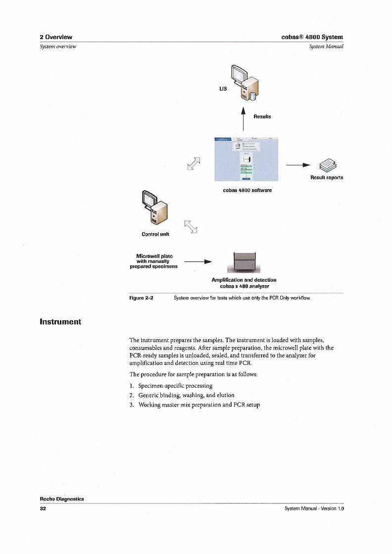
Tests that only use the PCR Only workflow, have the following components:
cobas 4800 software
Result reports
S
Sample preparationcobas x 480 instrument
Roche Diagnostics
System Manual Version 1.0 31
2 Overview
Systenz overview
cobas® 4800 System
System ivlanual
tControl ooit
LIS
t Resuits
•) .z=
cobas 4800 software
Result reports
Instrument
Roche Diagnostics
32
IVlicroweli platewith manually
prepared specimens
The instrument prepares the samples. The instrument is loaded with samples,consumables and reagents. After sample preparation, the microweli plate with thePCR-ready samples is unloaded, sealed, and transferred to the analyzer foramplification and detection using real time PCR.
The procedure for sample preparation is as follows;
1. Specimen-specific processing
2. Generic binding, washing, and elution
3. Working master mix preparation and PCR setup
0
Figure 2-2
Amplification and detectioncobas z 480 analyzer
System overview for tests which use only the PCR Only workflow.
System Manual . Version 1.0
cobas® 4800 System
Systeni Manual
2 Overview
Systeni overi’iew
Analyzer
Roche Diagnostics
System Manual . Version 1.0
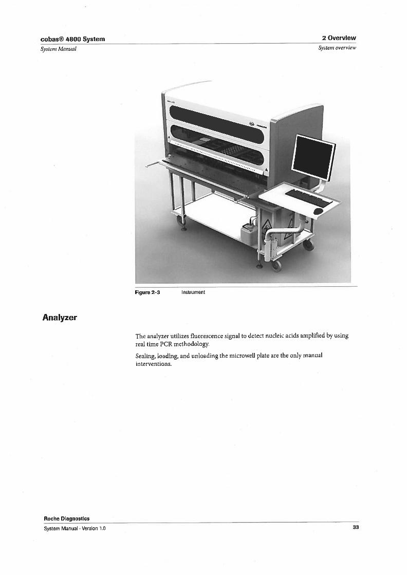
The analyzer utilizes fluorescence signal to detect nucleic acids amplified by usingreal time PCR methodologv.
Sealing, loading, and unloading the microweli plate are the only manualinterventions.
33
2 Overview cohas® 4800 System
Systent overview
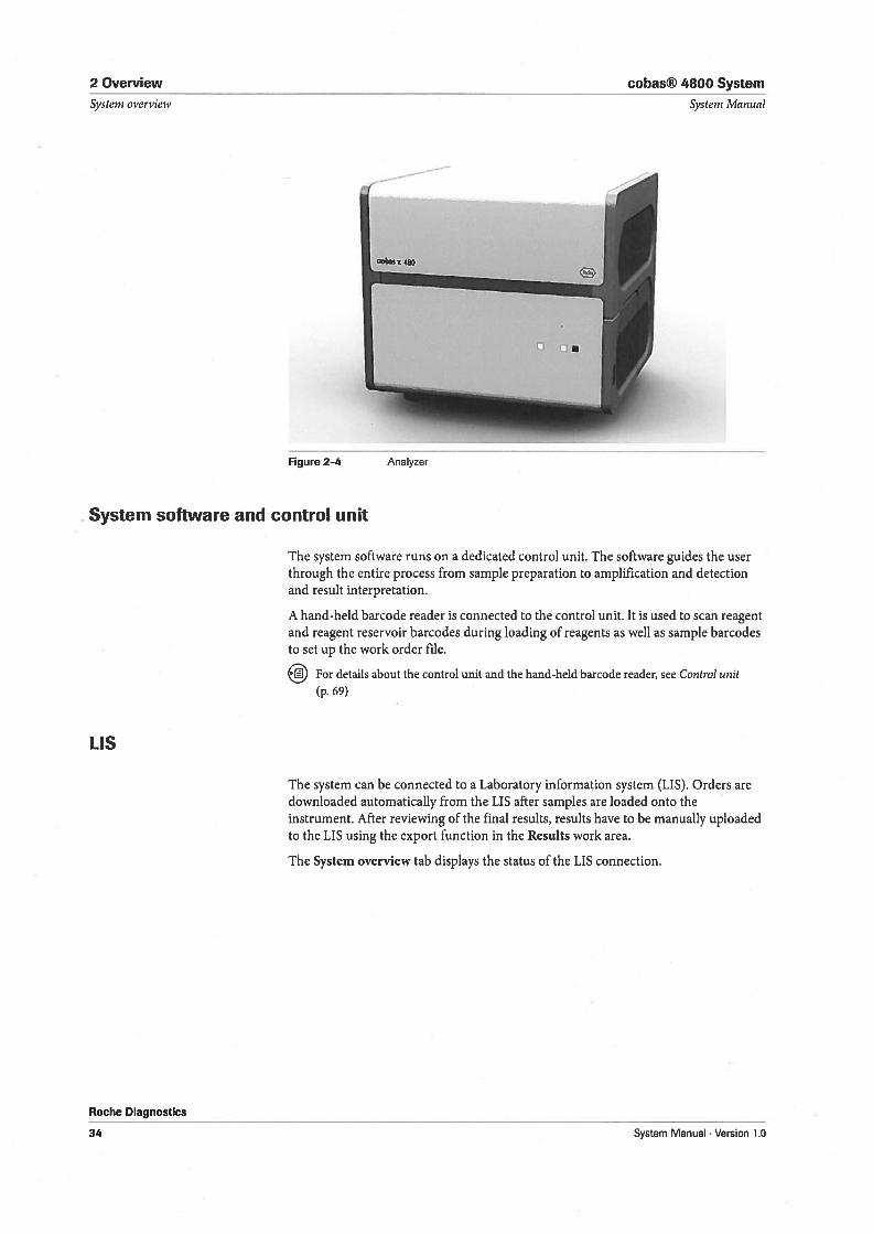
Figure 2-4
Systern Mannal
The system software runs on a dedicated control unit. The software guides the userthrough the entire process from sample preparation to amplification and detectionand result interpretation.
A hand-held barcode reader is connected to the control unit. It is used to scan reagentand reagent reservoir barcodes during loading of reagents as well as sample barcodesto set up the ivork order file.
For details about the control unit and the hand-held barcode reader, see Control unit
(p. 69)
The system can be connected to a Laboratory information system (LIS). Orders aredownloaded automatically from the LIS after samples are loaded onto theinstrument. After reviewing of the final results, results have to be manually uploadedto the LIS using the export function in the Results work area.
The System overview tab displays the status of the LIS connection.
Analyzer
System software and control unit
115
Roche Diagnostics
34 System Manual . Version 1.0
cobas® 4800 System 2 Overview
System Manual Systeni overvielv
os
[J [J .
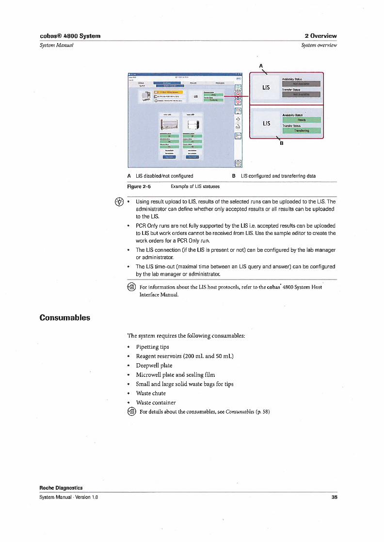
A [IS disabled/not configured B LIS configured and transferring data
Figure 2-5 Example of LIS statuses
• Using result upload to LIS, results of the selected runs can be uploaded to the LIS. Theadministrator can define whether only accepted resuits or all results can be uploadedto the [IS.
• PCR Only runs are not fully supported by the [IS i.e. accepted results can be uploadedto LIS but work orders cannot be received from LIS. Use the sample editor to create thework orders for a PCR Only run.
• The LIS connection (if the LIS is present or not) can be configured by the lab manageror administrator.
• The LIS time-out (maximal time between an LIS query and answer) can be configuredby the lab manager or administrator.
For information about the LIS host protocols, refer to the cobas 4800 System HostInterface Manual.
Consumables
The system requires the following consumables:
• Pipetting tips
• Reagent reservoirs (200 mL and 50 mL)
• Deepweil plate
• Microweli plate and sealing film
• Small and large solid waste bags for tips
• Waste chute
• Waste container
For details about the consumables, see Consurnables (p. 58)
Roche Diagnostics
System Manual . Version 1.0
-*,—
A
Adby St4os
1 CTrSt4,
Aveb(y
L ISTrnsemn5
B
35
2 Overview cobas® 4800 System
Systern overview Systern Man,ial
Roche Diagnostics
36 System Manual . Version 1.0
cobas® 4800 System 3 Hardware
Table of contents Systevn Manual
Hardware
In this chapter you get an introduction into the instrument.
In this chapter Chapter F1Instrument 39
Covers 40
LEDs 41
Instrument deck 41
Autoload unit 43
Pipetting arm 45
1SWAP 46
Teaching needies 46
Waste station 47
Carriers 50
Sample carriers 50
Reagent carriers 53
Plate carrier 55
Tip rack carriers 55
Stationary carrier 56
Consumables 58
Pipetting tips 58
Reagent reservoirs 58
Deepweli plate 59
Microweli plate 60
Consumables for tip waste 61
Secondary tubes 61
Technical specifications of the instrument 61
Analyzer 65
Main building bio cks 65
LEDs 67
Technical specifications of the analyzer 67
Control unit 69
Hand-held barcode reader 69
Technical specification of the control unit 70
Roche Diagnostics
System Manual . Version 1.0 37

3 Hardware cobas® 4800 System
Table of contents Systens Manual
Roche Diagnostics
38 System Manual Version to
cobas® 4800 System 3 Hardware
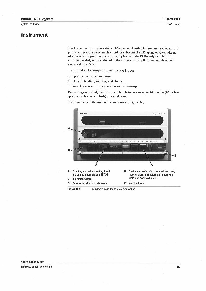
The instrument is an automated multi-channel pipetting instrument used to extract,purify, and prepare target nucleic acid for subsequent PCR testing on the analyzer.After sample preparation, the microweli plate with the PCR-ready samples isunloaded, sealed, and transferred to the analyzer for amplification and detectionusing real time PCR.
The procedure for sample preparation is as follows:
1. Specimen-specific processing
2. Generic binding, washing, and elution
3. Working master mix preparation and PCR-setup
Depending on the test, the instrument is able to process up to 96 samples (94 patientspecimens plus two controls) in a single run.
The main parts of the instrument are shown in Figure 3-1.
InstrumentSysteni Manual
Instrument
Roche Diagnostics
System Manual . Version 1.0
A Pipetting arm with pipetting head,8 pipetting channels, and ISWAP
B Instrument deck
C Autoloader with barcode reader
Figure 3—1 Instrument used for sample preparation
D Stationary carrier with heater/shaker unit,magnet plate, and holders for microweliplate and deepweli plate.
E Autoload tray
39
3 Hardware
Instrument
Covers
cobas® 4800 System
Systeni Manual
NOTICE
Roche Diagnostics
40
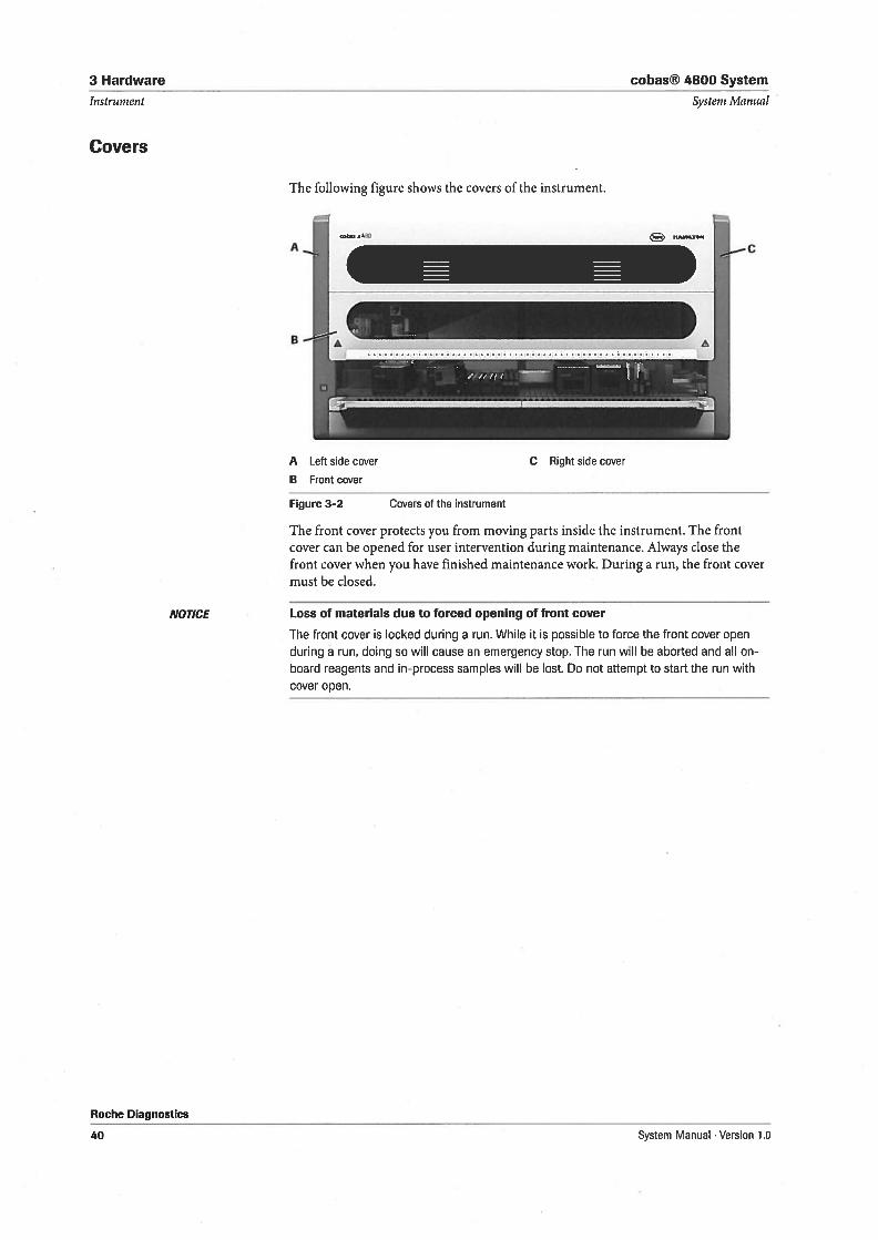
The following figure shows the covers of the instrument.
B Front cover
Figure 3-2 Covers of the instrument
The front cover protects you from moving parts inside the instrument. The frontcover can be opened for user intervention during maintenance. Always close thefront cover when you have finished maintenance work. During a run, the front covermust be closed.
Loss of materials due to forced opening of front cover
The front cover is locked during a run. While t is possible to force the front cover open
during a run, doing so will cause an emergency stop. The run will be aborted and all onboard reagents and in-process samples will be lost. Do not attempt to start the run withcover open.
A Left side cover C Right side cover
System Manual . Version 1.0
cobas® 4800 System 3 Hardware
Systeni Manual
LEDs
Instrument
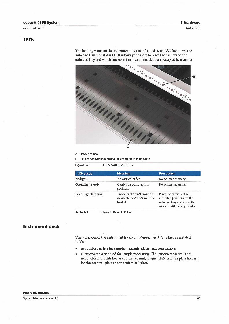
The loading status on the instrument deck is indicated by an LED bar above theautoload tray. The status LEDs inform you where to place the carriers on theautoload tray and which tracks on the instrument deck are occupied by a carrier.
A Track position
B [ED bar above the autoload indicating the loading status
Figure 3-3 [ED bar with status [EDs
LED status Meaning User action
No light No carrier loaded, No action necessary.
Green light steady Carrier on board at that No action necessary.position.
Green light blinking Indicates the track positions Place the carrier at thein which the carrier must be indicated positions on theloaded. autoload tray and insert the
carrier until the stop hooks.
Table 3-1 Status LEUs on LED bar
Instrument deck
The work area of the instrument is called instrument deck. The instrument deckhoids:
Roche Diagnostics
System Manual . Version 1.0
• removable carriers for samples, reagents, plates, and consumables.
• a stationary carrier used for sample processing. The stationary carrier is notremovable and hoids heater and shaker unit, magnet plate, and the plate holdersfor the deepweil plate and the microweil plate.
41
3 Hardware cobas® 4800 System
Instrument System Manual
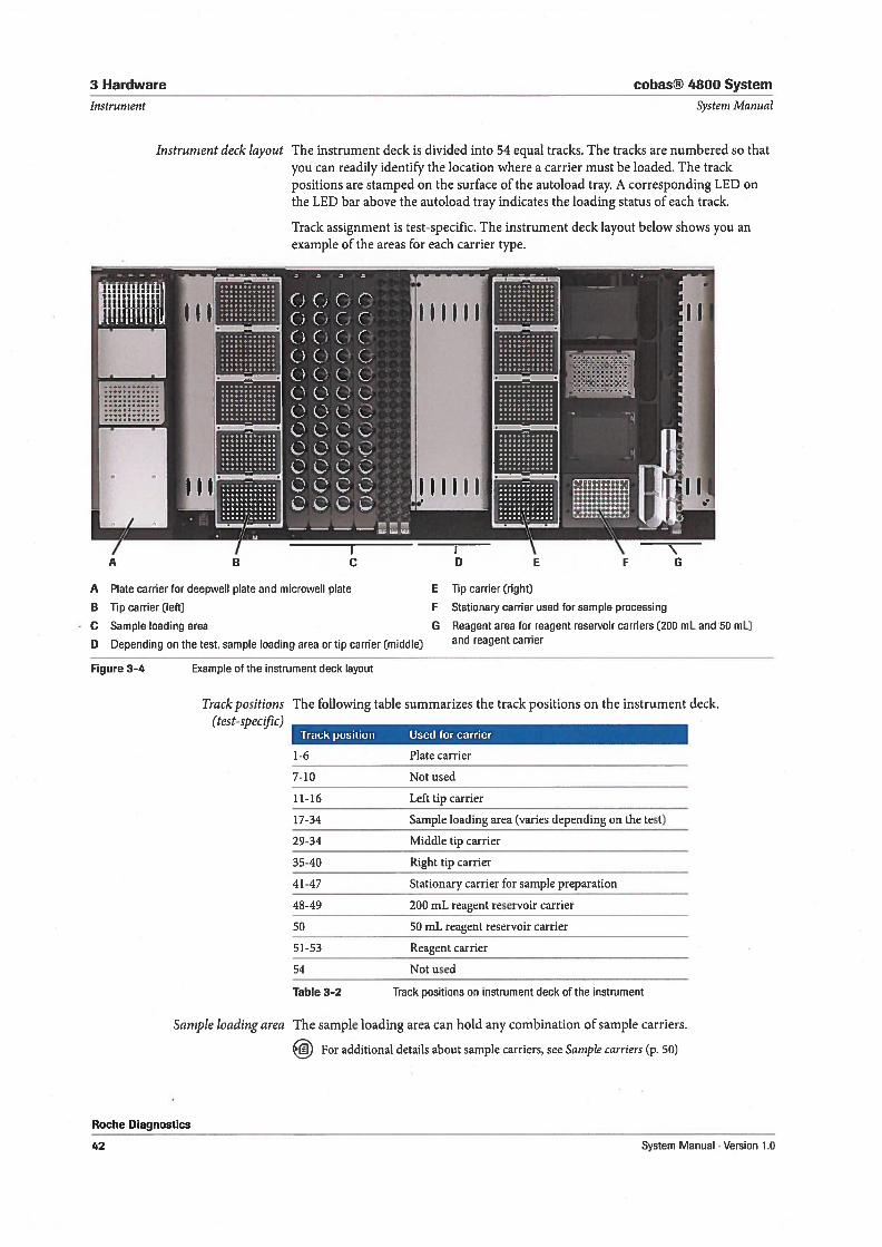
The instrument deck is divided into 54 equal tracks. The tracks are numbered so thatyou can readily identify the location where a carrier must be loaded. The trackpositions are stamped on the surface of the autoload tray. A corresponding LED onthe LED bar above the autoload tray indicates the loading status of each track.
Track assignment is test-specific. The instrument deck layout below shows you anexample of the areas for each carrier type.
A Plate carrier for deepweli plate and microwell plate
B Tip carrier (left)
C Sample loading area
D Depending on the test, sample loading area or tip carrier (middle)
Figure 3—4 Example of the instrument deck layout
Track positions(test-specijic)
The following table summarizes the track positions on the instrument deck.
Track position Used for carrier
1-6 Platecarrier
7-10 Not used
11-16 Left tip carrier
17-34 Sample loading area (varies depending on the test)
29-34 Middie tip carrier
35-40 Right tip carrier
4 1-47 Stationary carrier for sample preparation
48-49 200 mL reagent reservoir carrier
50 50 mL reagent reservoir carrier
51-53 Reagent carrier
54 Not used
Table 3-2 Track positions on instrument deck of the instrument
Roche Diagnostics
42
Sample loading area The sample loading area can hold any combination of sample carriers.
For additional details about sample carriers, see Sample carriers (p. 50)
Instrument deck layout
E Tip carrier (right)
F Stationary carrier used for sample processing
G Reagent area for reagent reservoir carriers (200 mL and 50 mL)and reagent carrier
System Manual Version 1.0
cobas® 4800 System 3 Hardware
NOTICE
Roche Diagnostics
System Manual . Version 1.0
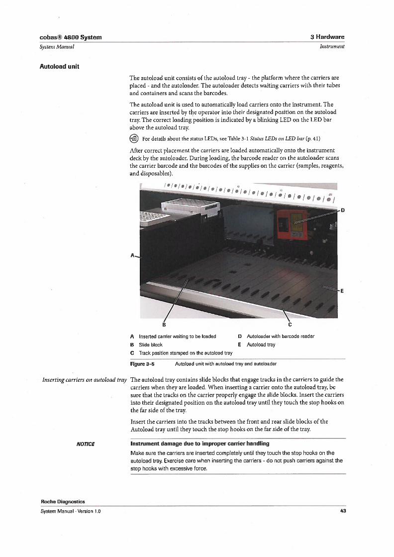
The autoload unit consists of the autoload tray - the platform where the carriers areplaced - and the autoloader. The autoloader detects waiting carriers with their tubesand containers and scans the barcodes.
The autoload unit is used to automatically bad carriers onto the instrument. Thecarriers are inserted by the operator into their designated position on the autoloadtray. The correct loading position is indicated by a blinking LED on the LED barabove the autoload tray.
jiJ For details about the status LEDs, see Table 3-1 Status LEDs on LED bar (p. 41)
After correct placement the carriers are loaded automatically onto the instrumentdeck by the autoloader. During loading, the barcode reader on the autoloader scansthe carrier barcode and the barcodes of the supplies on the carrier (samples, reagents,and disposables).
A Inserted carrierwaiting to be loaded
B Slide block
C Track position stamped on the autoload tray
Figure 3—5 Autoload unit with autoload tray and autoloader
The autoload tray contains slide bio cks that engage tracks in the carriers to guide thecarriers when they are loaded. When inserting a carrier onto the autoload tray, besure that the tracks on the carrier properly engage the slide blocks. Insert the carriersinto their designated position on the autoboad tray until they touch the stop hooks onthe far side of the tray.
Insert the carriers into the tracks between the front and rear slide blocks of theAutoboad tray until they touch the stop hooks on the far side of the tray.
Instrument damage due to improper carrier handling
Make sure the carriers are inserted completely until they touch the stop hooks on the
autoload tray Exercise care when inserting the carriers - do not push carriers against the
stop hooks with excessive force.
InstrumentSysteni Manual
Autoload unit
Inserting carriers on autoload tray
D Autoloaderwith barcode reader
E Autoload tray
43
3 Hardware cobas® 4800 System
Instrument Systeni Manual
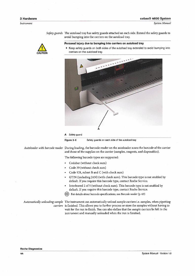
Safety guards The autoload tray has safety guards attached on each side. Extend the safety guards toavoid bumping into the carriers on the autoload tray.
Personal injury due to bumping into carriers on autoload tray
Keep safety guards on both sides of the autoload tray extended to avoid bumping into
carriers on the autoload tray
Autoloader with barcode reader During loading, the barcode reader on the autoloader scans the barcode of the carrierand those of the supplies on the carrier (samples, reagents, and disposables).
The following barcode types are supported:
• Codabar (without check sum)
• Code 39 (without check sum)
• Code 128, subset B and C (with check sum)
• GTIN (inciuding JAN) (with check sum). This barcode type is not enabled bydefault. 1f you require this barcode type, contact Roche Service.
• Interleaved 2 of 5 (without check sum). This barcode type is not enabled bydefault. 1f you require this barcode type, contact Roche Service.
For details about barcode specifications, see Barcode reader (p. 63)
Auto matically unloading samplecarriers
Roche tiiagnostics
The instrument can automatically unload sample carriers i.e. samples, when pipettingis finished. This allows you to further process or store the samples without having towait for the run to finish. You can also define that the sample carriers be left in theinstrument and manually unloaded when the run is finished.
CAUTION
• S --
è --‘-
1
A Satetyguard
Figure 3—6 Satety guards on each side of the autoload tray
44 System Manual . Version 1.0
cobas® 4800 System 3 Hardware
Systeni Manual
Pipetting arm
Instrument
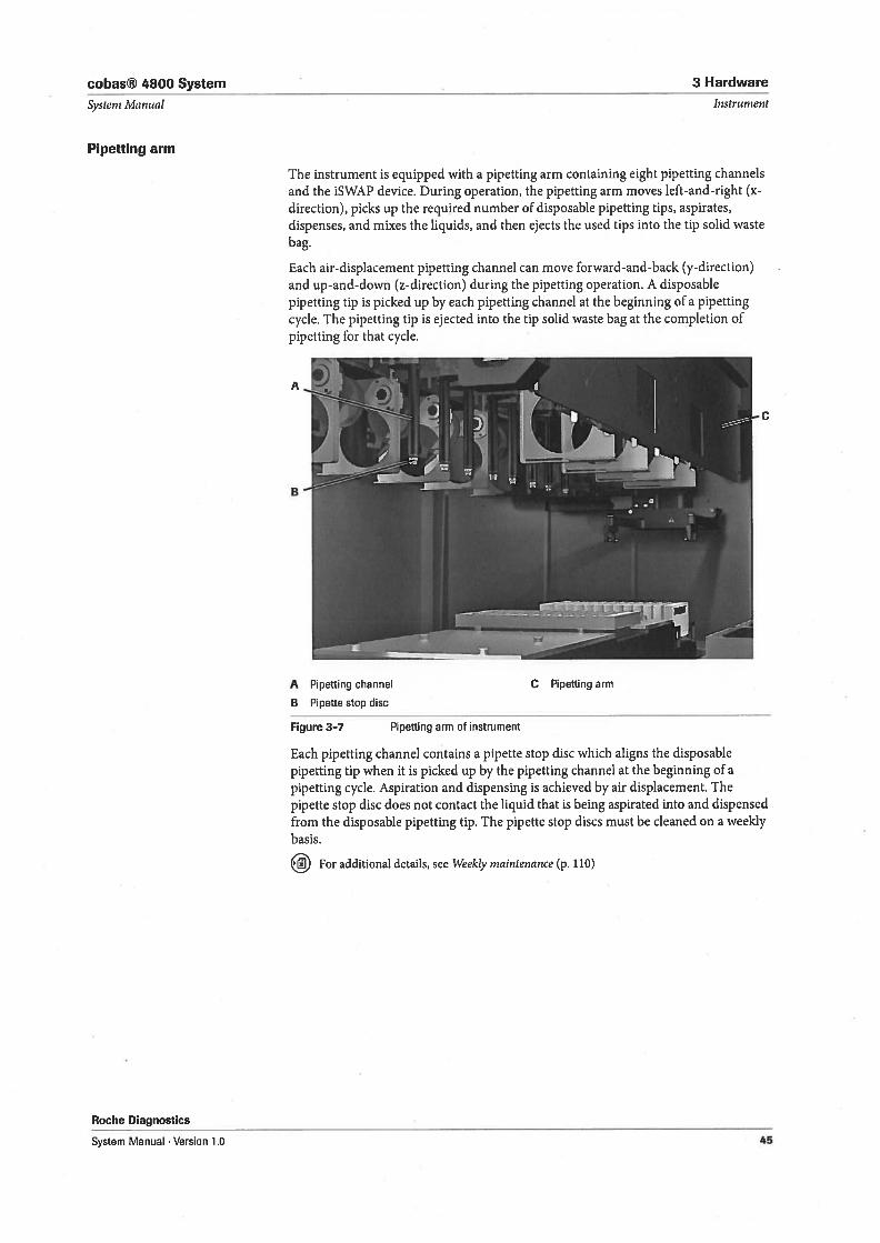
The instrument is equipped with a pipetting arm containing eight pipetting channelsand the iSWAP device. During operation, the pipetting arm moves left-and-right (xdirection), picks up the required number of disposable pipetting tips, aspirates,dispenses, and mixes the liquids, and then ejects the used tips into the tip solid wastebag.
Each air-displacement pipetting channel can move forward-and-back (y-direction)and up-and-down (z-direction) during the pipetting operation. A disposablepipetting tip is picked up by each pipetting channel at the beginning of a pipettingcycle. The pipetting tip is ejected into the tip solid waste bag at the completion ofpipetting for that cycle.
Figure 3-7 Pipetting arm of instrument
Roche Diagnostics
Each pipetting channel contains a pipette stop disc which aligns the disposablepipetting tip when it is picked up by the pipetting channel at the beginning of apipetting cycle. Aspiration and dispensing is achieved by air displacement. Thepipette stop disc does not contact the liquid that is being aspirated into and dispensedfrom the disposable pipetting tip. The pipette stop discs must be cleaned on a weeklybasis.
For additional details, see Weekly niaintenance (p. 110)
A Pipetting channel C Pipetting arm
B Pipette stop disc
System Manual Version 1.0 45
3 Hardware cobas® 4800 System
Instrument
iSWAP
Teaciting needies
System Manual
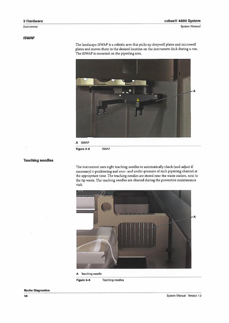
The landscape iSWAP is a robotic arm that picks up deepweli plates and microweliplates and moves them to the desired location on the instrument deck during a run.The ISWAP is mounted on the pipetting arm.
Figure 3-8 ISWAP
Roche Diagnostics
The instrument uses eight teaching needies to automatically check (and adjust ifnecessary) z-positioning and over- and under-pressure of each pipetting channel atthe appropriate time. The teaching needies are stored near the waste station, next tothe tip waste. The teaching needies are cleaned during the preventive maintenancevisit.
Figure 3-9 Teaching needles
A iSWAP
A Teaching needle
46 System Manual . Version 1.0
cobas® 4800 System 3 Hardware
Systern Manual
Waste station
Safety information
Instrument
Roche Diagnostics
System Manual . Version 1.0
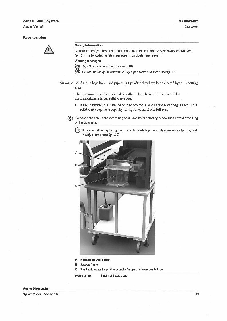
Make sure that you have read and understood the chapter General safety information(p. 13). The following safety messages in particular are relevant:
Warning messages:
Infection by biohazardous waste (p. 19)
Contanination of the environment by liquid waste and solid waste (p. 19)
Tip waste Solid vaste bags hold used pipetting tips after they have been ejected by the pipettingarm.
The instrument can be installed on either a bench top or on a trolley thataccommodates a larger solid waste bag.
• 1f the instrument is installed on a bench top, a small solid waste bag is used. Thissolid waste bag has a capacity for tips of at most one full run.
E9 Exchange the small solid waste bag each time before starting a new run to avoid overfillingof the tip waste.
For details about replacing the small solid waste bag, see Daily niaintenance (p. 105) andVeekly niaintenance (p. 110)
A Initialization/waste block
B Support frame
C Small solid waste bag with a capacity for tips of at most one full run
Figure 3—10 Small solid waste bag
47
3 Hardware cobas® 4800 System
Instrument
Roche Diagnostics
Systeni Manual
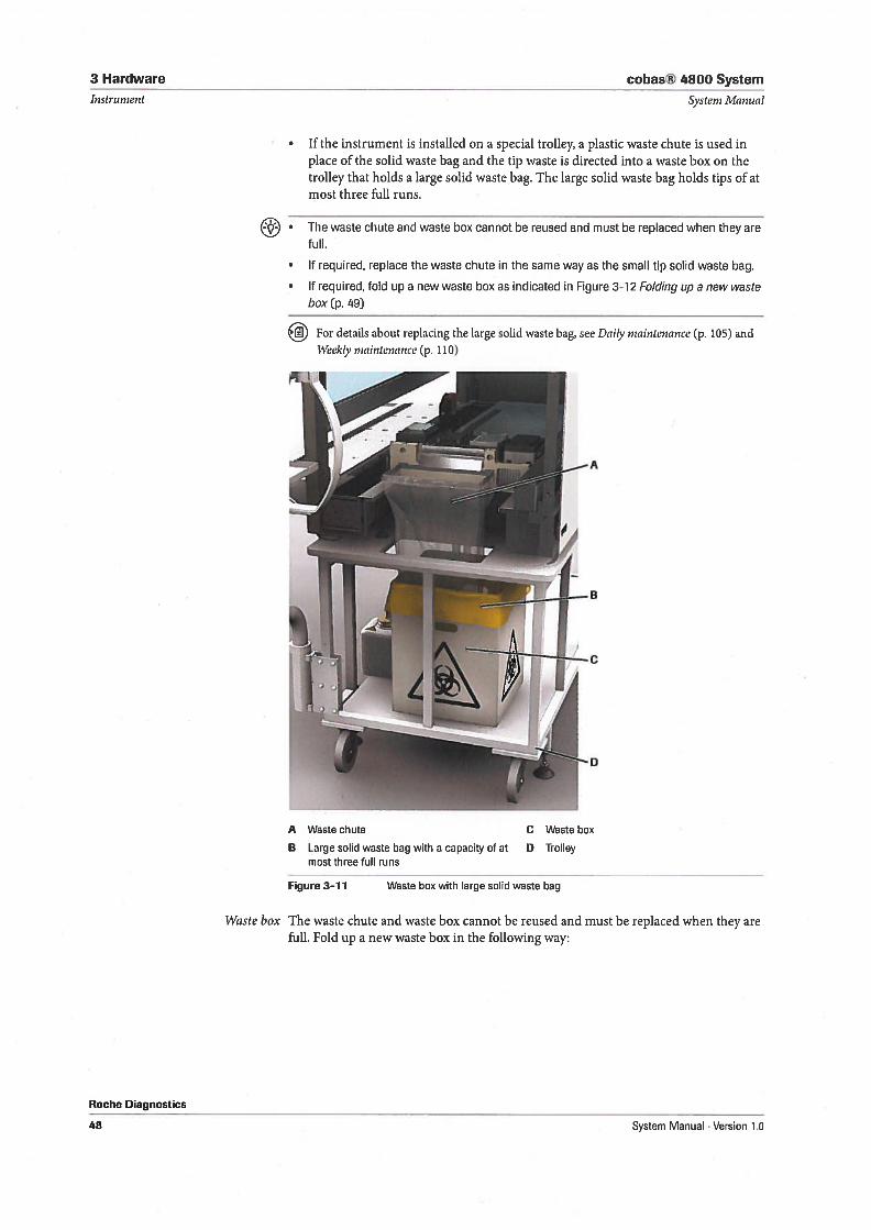
1f the instrument is installed on a special trolley, a plastic waste chute is used inplace of the solid waste bag and the tip waste is directed into a waste box on thetrolley that hoids a large solid waste bag. The large solid waste bag holds tips of atmost three full runs.
• The waste chute and waste box cannot be reused and must be replaced when they arefull.
• 1f required, replace the waste chute in the same way as the small tip solid waste bag.
• 1f required, fold up a new waste box as indicated in Figure 3-12 Folding up a new wastebox (p. 49)
For details about replacing the large solid waste bag, see Daily maintenance (p. 105) andWeekly maintenance (p. 110)
A Wastechute
B Large solid waste bag with a capacity of atmost three full runs
Figure 3-11 Waste box with large solid waste bag
Waste box The waste chute and waste box cannot be reused and must be replaced when they arefull. Fold up a new waste box in the following way:
C Waste box
D Trolley
48 System Manual . Version 1.0
cobas® 4800 System 3 Hardware
Systern Manual Instrument
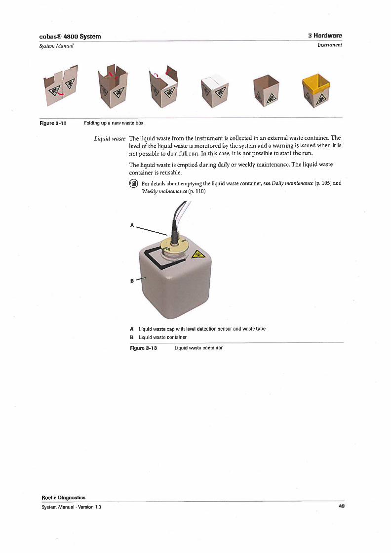
Liquid waste The liquid waste from the instrument is collected in an external waste container. Thelevel of the liquid waste is monitored by the system and a warning is issued when it isnot possible to do a full run. In this case, it is not possible to start the run.
The liquid vaste is emptied during daily or weekly maintenance. The liquid wastecontainer is reusable.
For details about emptying the liquid waste container, see Daily maintenance (p. 105) and
tVeekly maintenance (p. 110)
A
A Liquid waste cap with level detection sensor and waste tube
B Liquid waste container
Roche Diagnostics
Figure 3-13 Liquid waste container
Figure 3-12 Folding up a new waste box
//
System Manual Version 1.0 49
3 Hardware
Instrument
Carriers
cobas® 4800 System
System Manual
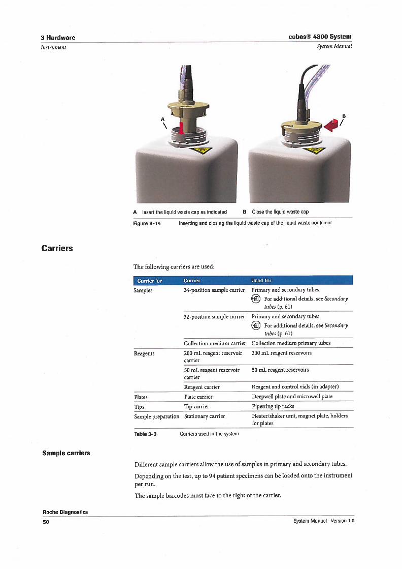
A Insert the liquid waste cap as indicated B Close the liquid waste cap
Figure 3—14 Inserting and closing the liquid waste cap of the liquid waste container
The following carriers are used:
Camer for Carrier Used for
Sample carriers
Primary and secondary tubes.
For additional details, see Secondaytubes (p. 61)
Primary and secondary tubes.
For additional details, see Secondary
tubes (p. 61)
Collection medium primary tubes
200 mL reagent reservoirs
Roche Diagnostics
Different sample carriers allow the use of samples in primary and secondary tubes.
Depending on the test, up to 94 patient specimens can be loaded onto the instrument
per run.
The sample barcodes must face to the right of the carrier.
Samples 24-position sample carrier
32-position sample carrier
Collection medium carrier
Reagents 200 mL reagent reservoircarrier
50 mL reagent reservoir 50 mL reagent reservoirscarrier
Reagent carrier Reagent and control vials (in adapter)
Plates Plate carrier Deepweli plate and microweli plate
Tips Tip carrier Pipetting tip racks
Sample preparation Stationary carrier Heater/shaker unit, magnet plate, holdersfor plates
Table 3-3 Carriers used in the system
50 System Manual Version 1.0
cobas® 4800 System 3 Hardware
Systeni Manual Instrument
Each run has test specific controls e.g. positive/negative control. Controls are loadedtogether with the reagents onto the reagent carrier.
NOTICE Instrument damage due to the use of inappropriate or closed tubes
Using the incorrect tube types or closed tubes en sample carriers can damage theinstrument
Use only specified tube types for sample carriers.
Do not use closed tubes en sample carriers. Always open tubes on all sample carriers.
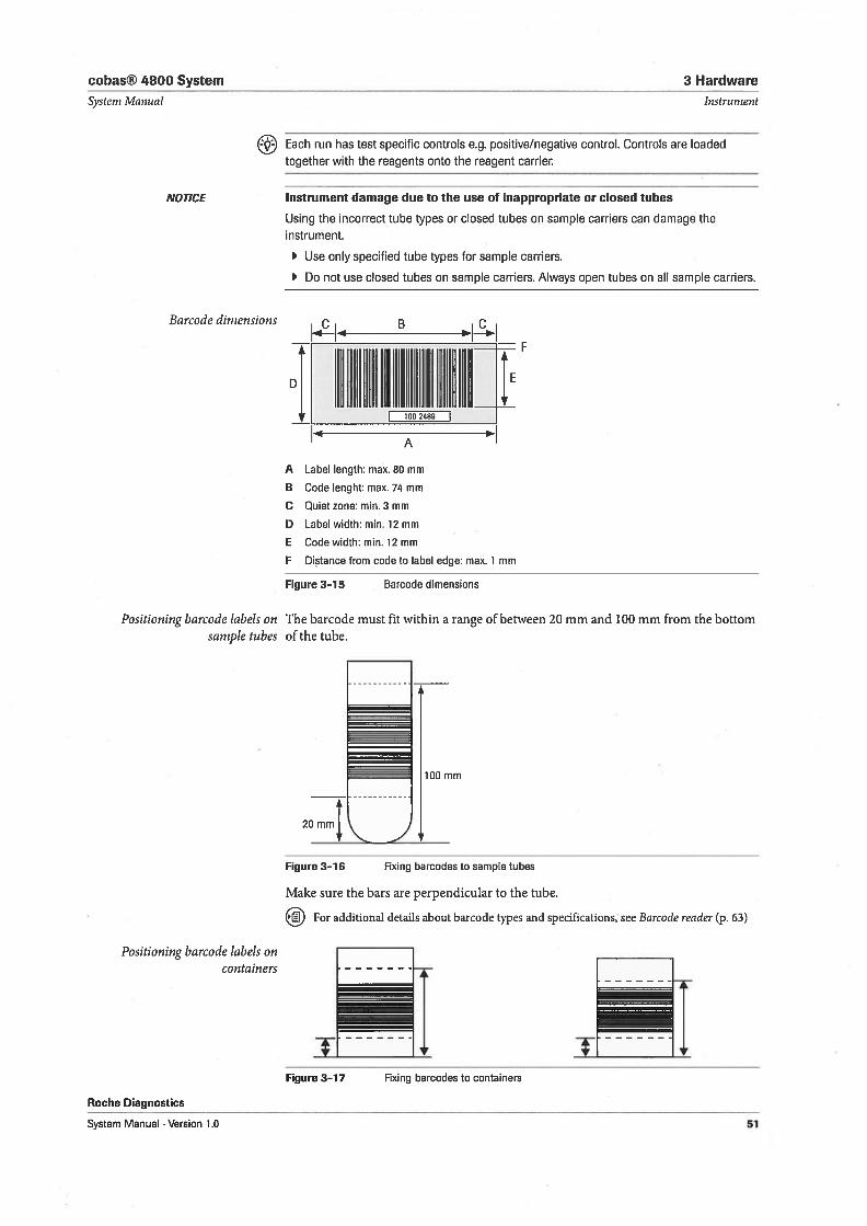
Barcode dirnensions c B c
U.
EL1
A
A Label length: max. 80 mm
B Code Ienght: max. 74 mm
C Quiet zone: min. 3 mm
D Label width: min. 12 mm
E Code width: min. 12 mm
F Distance from code to label edge: max. 1 mm
Fi9ure 3-15 Barcode dimensions
Positioning barcode labels on The barcode must fit within a range of between 20 mm and 100 mm from the bottomsample tubes of the tube.
100 mm
2OmmL
Figure 3—16 Fixing barcodes to sample tubes
Make sure the bars are perpendicular to the tube.
For additional details about barcode types and specifications, see Barcode reader (p. 63)
Positioning barcode labels oncontainers
Figure 3—17 Fixing barcodes to containers
Roche Diagnostics
System Manual . Version 1.0 51
3 Hardware
Instrument
cobas® 4800 System
Systenz Manual
24-position saniple carrier(test-specflc)
CAUTION
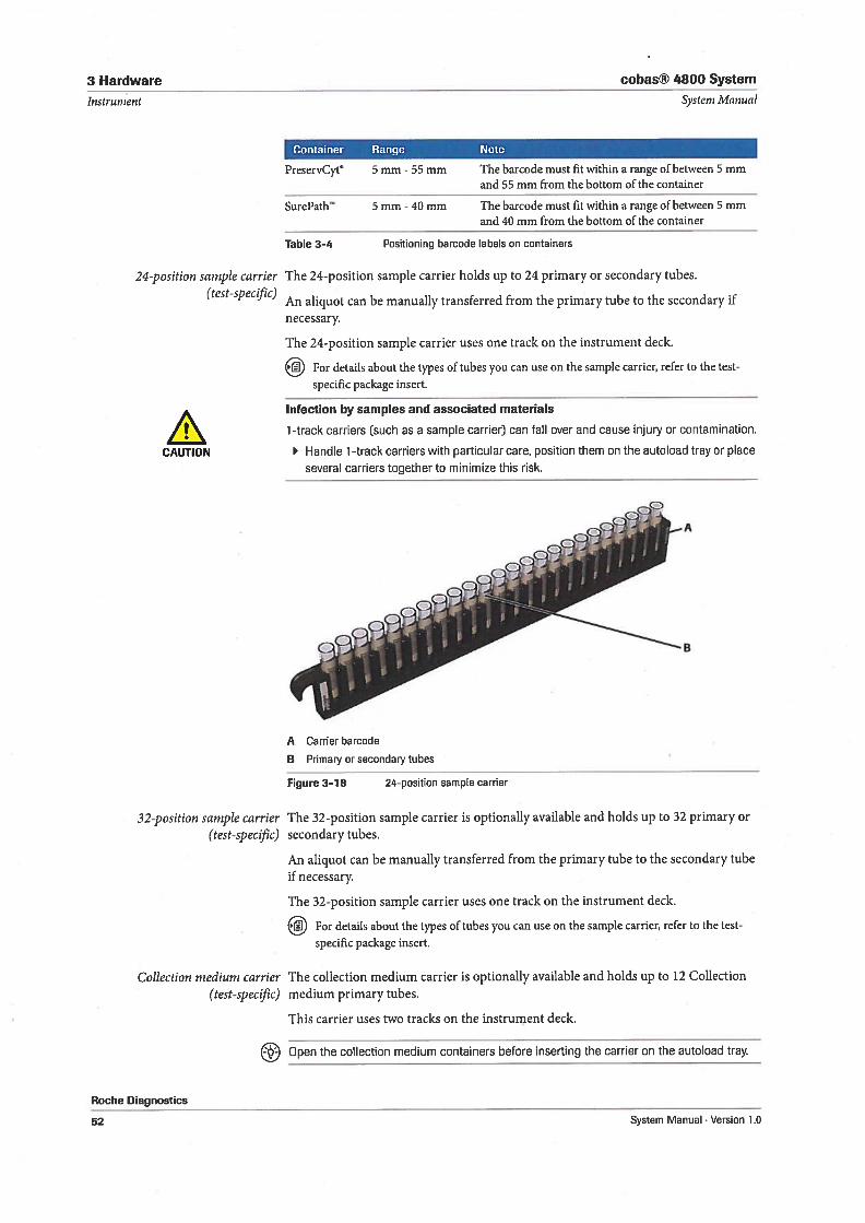
Container Range Note
PreservCyt 5 mm - 55 mm The barcode must fit within a range of between 5 mmand 55 mm from the bottom of the container
SurePalh’ 5 mm -40 mm The barcode must fit within a range of between 5 mmand 40 mm from the bottom of the container
Table 3-4 Positioning barcode labels on containers
The 24-position sample carrier hoids up to 24 primary or secondary tubes.
An aliquot can be manually transferred from the primary tube to the secondary ifnecessary.
The 24-position sample carrier uses one track on the instrument deck.
EJ3 For details about the types of tubes you can use on the sample carrier, refer to the testspecific package insert.
Infection by samples and associated materials
1-track carriers (such as a sample carrier) can fall over and cause injury or contamination.
Handle 1 -track carriers with particular care, position them on the autoload tray or placeseveral carriers together to minimize this risk.
Roche Diagnostics
A Carrier barcode8 Primary or secondary tubes
Figure 3-18 24-position sample carrier
The 32-position sample carrier is optionally available and hoids up to 32 primary orsecondary tubes.
An aliquot can be manually transferred from the primary tube to the secondary tubeif necessary.
The 32-position sample carrier uses one track on the instrument deck.
For details about the types of tubes you can use on the sample carrier, refer to the testspecific package insert.
The collection medium carrier is optionally available and hoids up to 12 Collectionmedium primary tubes.
This carrier uses two tracks on the instrument deck.
Open the collection medium containers before inserting the carrier on the autoload tray.
t—
•1v
,- S.
B
32-position sample carrier(test-specfic)
Collection medium carrier(test-specfic)
52 System Manual Version 1.0
cobas® 4800 System
Systern Man ual
3 Hardware
Instrument
Reagent carriers
Reagent reservoir carriers
Roche Diagnostics
System Manual . Version 1.0
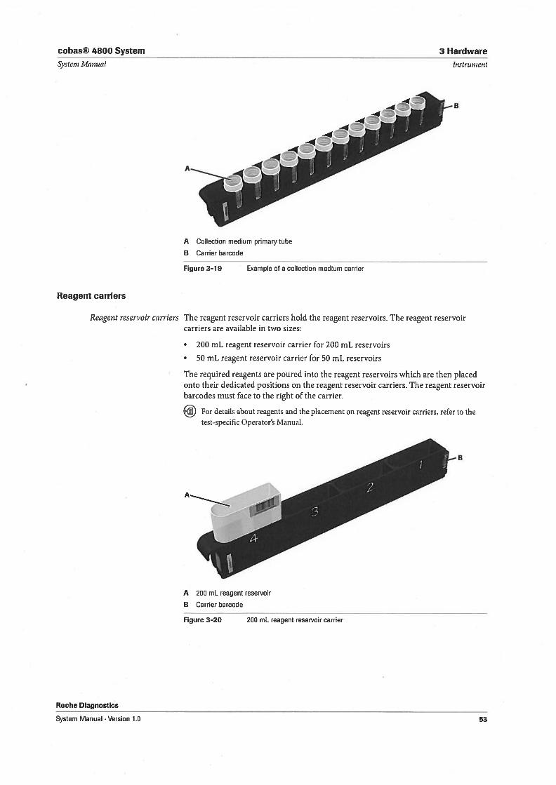
A Collectiori medium primary tube
B Carrier barcode
[igure 3—19 Example of a collection medium carrier
The reagent reservoir carriers hold the reagent reservoirs. The reagent reservoircarriers are available in two sizes:
• 200 mL reagent reservoir carrier for 200 mL reservoirs
• 50 mL reagent reservoir carrier for 50 mL reservoirs
The required reagents are poured into the reagent reservoirs which are then placedonto their dedicated positions on the reagent reservoir carriers. The reagent reservoirbarcodes must face to the right of the carrier.
For details about reagents and the placement on reagent reservoir carriers, refer to thetest-specific Operator’s Manual.
A 200 mL reagent reservoir
B Carrier barcode
Figure 3-20 200 mL reagent reservoir carrier
Aø
53
3 Hardware cobas® 4800 System
Instrument
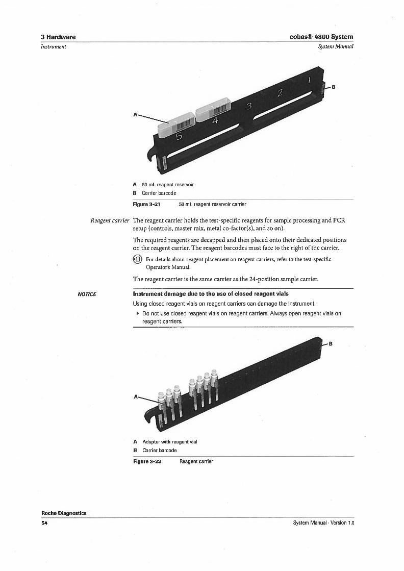
A 50 mL reagent reservoir
B Carrier barcode
Systeni Manual
Figure 3—21 50 mL reagent reservoir carrier
Reagent carrier The reagent carrier hoids the test-specific reagents for sample processing and PCRsetup (controls, master mix, metal co-factor(s), and so on).
The required reagents are decapped and then placed onto their dedicated positionson the reagent carrier. The reagent barcodes must face to the right of the carrier.
For details about reagent placement on reagent carriers, refer to the test-specificOperator’s Manual.
The reagent carrier is the same carrier as the 24-position sample carrier.
NOTICE
Roche Diagnostics
Instrument damage due to the use of closed reagent vials
Using closed reagent vials on reagent carriers can damage the instrument.
Do not use closed reagent vials on reagent carriers. Always open reagent vials on
reagent carriers.
A Adapter with reagent vial
B Carrier barcode
Figure 3—22 Reagent carrier
g
A
54 System Manual . Version 1.0
cobas® 4800 System 3 Hardware
Systent Manual
Plate carrier
Instrument
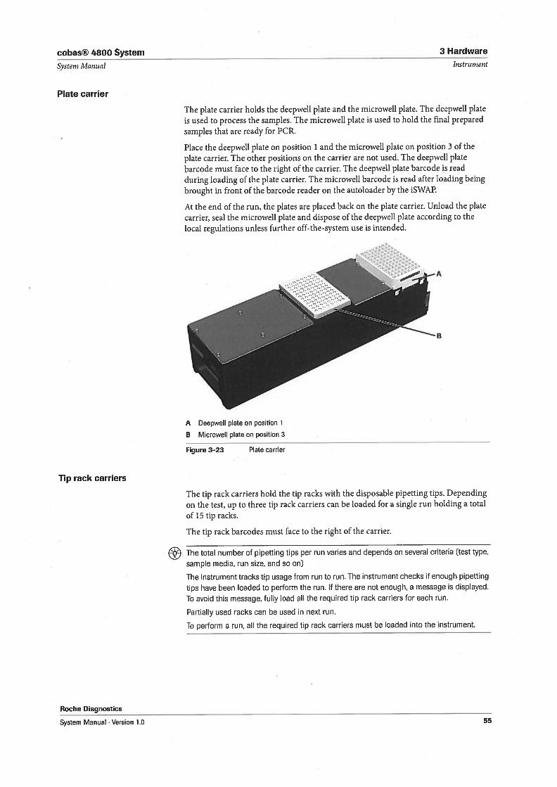
The plate carrier hoids the deepweli plate and the microweli plate. The deepweil plateis used to process the samples. The microweli plate is used to hold the final preparedsamples that are ready for PCR.
Place the deepweil plate on position 1 and the microweli plate on position 3 of theplate carrier. The other positions on the carrier are not used. The deepweli platebarcode must face to the right of the carrier. The deepweil plate barcode is readduring loading of the plate carrier. The microweil barcode is read after loading beingbrought in front of the barcode reader on the autoloader by the iSWAP.
At the end of the run, the plates are placed back on the plate carrier. Unload the platecarrier, seal the microweil plate and dispose of the deepweil plate according to thelocal regulations unless further off-the-system use is intended.
Tip rack carriers
Figure 3-23 Plate carrier
The tip rack carriers hold the tip racks with the disposable pipetting tips. Dependingon the test, up to three tip rack carriers can be loaded for a single run holding a totalof 15 tip racks.
The tip rack barcodes must face to the right of the carrier.
Roche Diagnostics
The total number of pipetting tips per run varies and depends on several criteria (test type,
sample media, run size, and so on)
The instrument tracks tip usage from run to run. The instrument checks if enough pipetting
tips have been loaded to perform the run. 1f there are not enough, a message is displayed.
To avoid this message, fully bad all the required tip rack carriers for each run.
Partially used racks can be used in next run.
To perform a run, all the required tip rack carriers must be loaded into the instrument.
A Deepweli plate on position 1
B Microweli plate on position 3
System Manual Version 1.0 55
3 Hardware cobas® 4800 System
Instrument
Stationary carrier
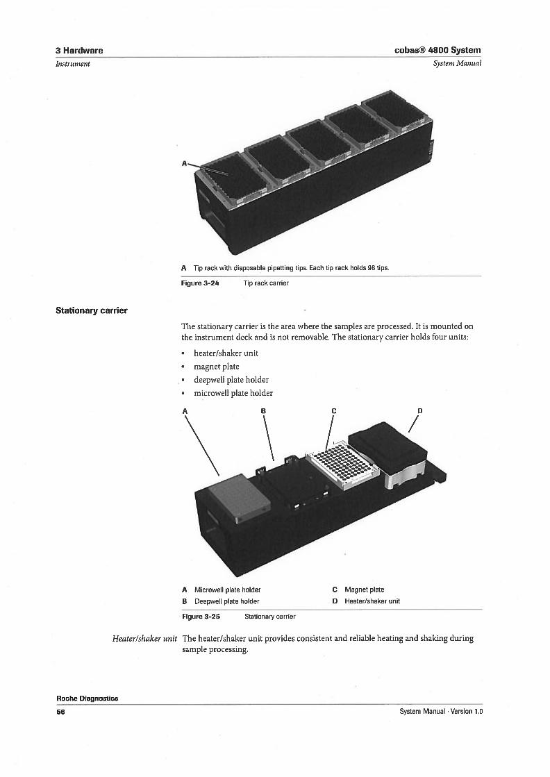
Figure 3-24 Tip rack carrier
Systeni Manual
The stationary carrier is the area where the samples are processed. It is mounted onthe instrument deck and is not removable. The stationary carrier hoids four units:
• heater/shaker unit
• magnet plate
• deepweli plate holder
• microwell plate holder
A Microweli plate holder
B Deepweil plate holder
Figure 3-25 Stationary carrier
Heater/shaker unit The heater/shaker unit provides consistent and reliable heating and shaking duringsample processing.
A Tip raak with disposable pipetting tips. Each tip rack holds 96 tips.
C Magnet plate
13 Heater/shaker unit
Roche Diagnostics
56 System Manual . Version 1.0
cobas® 4800 System 3 Hardware
Systern Manual Instrument
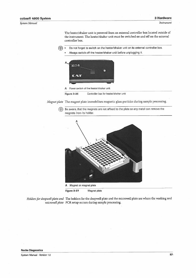
The heater/shaker unit is powered from an external controller box located outside ofthe instrument. The heater/shaker unit must be switched on and offon the externalcontroller box.
Do not forget to switch on the heater/shaker unit on its external controller box.
Always switch off the heater/shaker unit before unplugging It.
A
P Power switch of the heater/shaker unit
Figure 3-26 Controller box for heater/shaker unit
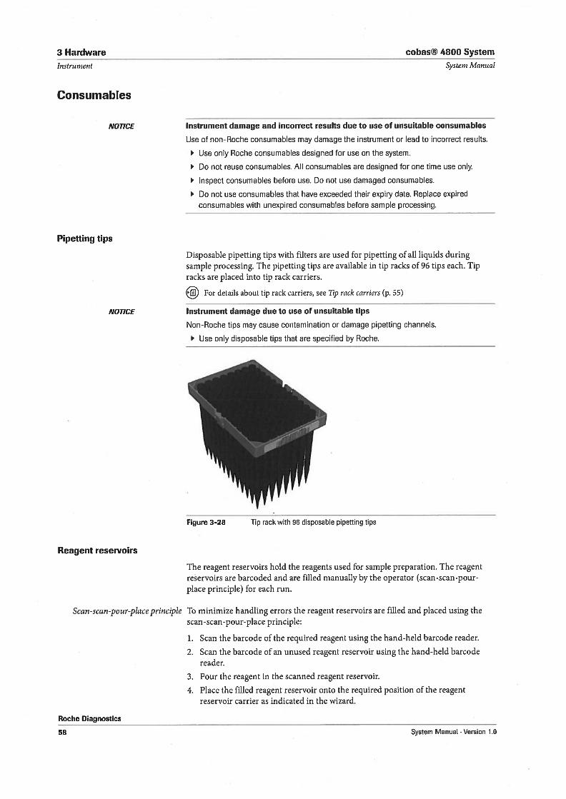
Magnetpiate The magnet plate immobilizes magnetic glass particles during sample processing.
Be aware, that the magnets are not affixed to the plate so any metal can remove the
magnets from its holder.
Figure 3-27 Magnet plate
Holdersfor deepweil plate and The holders for the deepweli plate and the microweli plate are where the washing andmicroweliplate PCR setup occurs during sample processing.
Roche Diagnostics
A Magnet on magnet plate
System Manual . Version 1.0 57,
3 Hardware cobas® 4800 System
Instrument System Manual
Consumables
NOTICE Instrument damage and incorrect resuits due to use of unsuitable consumables
Use of non-Roche consumables may damage the instrument or lead to incorrect resuits.
Use only Roche consumables designed for use on the system.
Do not reuse consumables. All consumables are designed for one time use only.
Inspect consumables before use. Do not use damaged consumables.
Do not use consumables that have exceeded their expiry date. Replace expiredconsumables with unexpired consumables before sample processing.
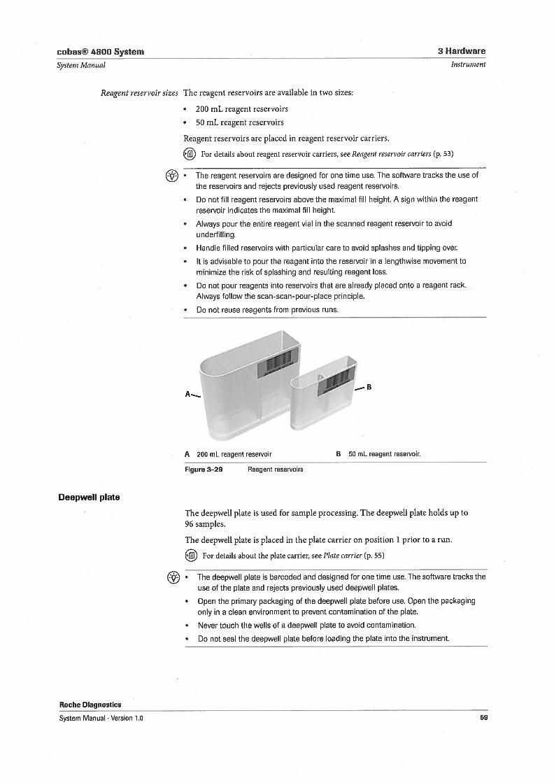
Pipetting tips
Disposable pipetting tips with filters are used for pipetting of all liquids duringsample processing. The pipetting tips are available in tip racks of 96 tips each. Tipracks are placed into tip rack carriers.
For details about tip rack carriers, see Tip rack carriers (p. 55)
NOTICE Instrument damage due to use of unsuitable tips
Non-Roche tips may cause contamination or damage pipetting channels.
Use only disposable tips that are specified by Roche.
Figure 3—28 Tip rack with 96 disposable pipetting tips
Reagent reservoirs
The reagent reservoirs hold the reagents used for sample preparation. The reagentreservoirs are barcoded and are filled manually by the operator (scan-scan-pourplace principle) for each run.
Scan-scan-pour-placeprinciple To minimize handling errors the reagent reservoirs are filled and placed using thescan-scan-pour-place principle:
1. Scan the barcode of the required reagent using the hand-held barcode reader.
2. Scan the barcode of an unused reagent reservoir using the hand-held barcodereader.
3. Pour the reagent in the scanned reagent reservoir.
4. Place the filled reagent reservoir onto the required position of the reagentreservoir carrier as indicated in the wizard.
Roche Diagnostics
58 System Manual . Version 1.0
cobas® 4800 System 3 Hardware
Systern ?vlanual Jos trument
Reagent reservoir sizes The reagent reservoirs are available in two sizes:
• 200 mL reagent reservoirs
• 50 mL reagent reservoirs
Reagent reservoirs are placed in reagent reservoir carriers.
For details about reagent reservoir carriers, see Reagent reservoir carriers (p. 53)
• The reagent reservoirs are designed for one time use. The software tracks the use of
the reservoirs and rejects previously used reagent reservoirs.
• Do not fiN reagent reservoirs above the maximal filI height. A sign within the reagent
reservoir indicates the maximal fili height.
• Always pour the entire reagent vial in the scanned reagent reservoir to avoid
underfilling.
• Handle filled reservoirs with particular care to avoid spiashes and tipping over.
• It is advisable to pour the reagent into the reservoir in a lengthwise movement to
minimize the risk of spiashing and resulting reagent loss.
• Do not pour reagents into reservoirs that are already placed onto a reagent rack.
Always follow the scan-scan-pour-place principle.
• Do not reuse reagents from previous runs.
A 200 mL reagent reservoir B 50 mL reagent reservoir.
Figure 3-29 Reagent reservoirs
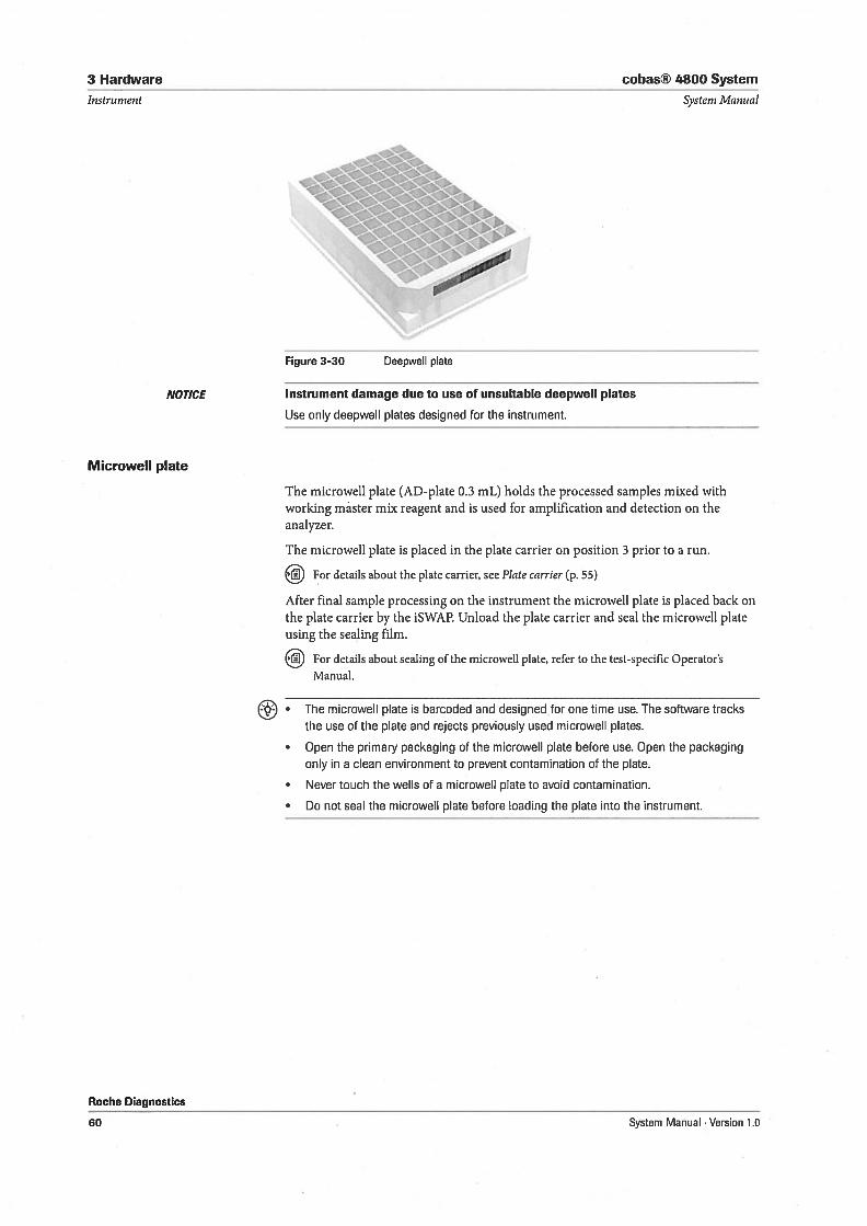
Deepweli plate
The deepweil plate is used for sample processing. The deepweil plate hoids up to96 samples.
The deepweil plate is placed in the plate carrier on position 1 prior to a run.
For details about the plate carrier, see Plate carrier (p. 55)
• The deepweli plate is barcoded and designed for one time use. The software tracks the
use of the plate and rejects previously used deepweli plates.
• Open the primary packaging of the deepweli plate before use. Open the packaging
only in a clean environment to prevent contamination of the plate.
• Never touch the weNs of a deepweli plate to avoid contamination.
• Do not seal the deepwell plate before loading the plate into the instrument.
Roche Diagnostics
System Manual . Version 1.0 59
3 Hardware
Instrument
NOTICE
Microweli plate
cobas® 4800 System
Systeni !ulanual
The microweli plate (AD-plate 0.3 mL) hoids the processed samples mixed withworking master mix reagent and is used for amplification and detection on theanalyzer.
The microweli plate is placed in the plate carrier on position 3 prior to a run.
For details about the plate carrier, see Plate carrier (p. 55)
After final sample processing on the instrument the microweil plate is placed back onthe plate carrier by the iSWAP. Unload the plate carrier and seal the microweli plateusing the sealing film.
iJ For details about sealing of the microweli plate, refer to the test-specific Operator’sManual.
Roche Diagnostics
The microweil plate is barcoded and designed for one time use. The software tracksthe use of the plate and rejects previously used microweli plates.
• Open the primary packaging of the microweli plate before use. Open the packagingonly in a clean environment to prevent contamination of the piste.
• Never touch the weils of a microweil piste to avoid contamination.
• Do not seal the microweli piste before loading the piste into the instrument.
[
Figure 3-30 Deepweil piste
Instrument damage due to use of unsuitable deepweil plates
Use only deepweil plates designed for the instrument.
60 System Manual . Version 1.0
cobas® 4800 System
System A’fanual
N
3 Hardware
Instrument
Br
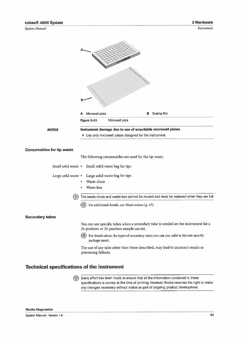
A Microweil plate
[igure 3-31 Microweli plate
B Sealing film
NOTICE
Consumables for tip waste
Instrument damage due to use of unsuitable microweil plates
Use only microwell plates designed for the instrument.
The following consumables are used for the tip vaste.
Small solid waste • Small solid waste bag for tips
Large solid waste • Large solid waste bag for tips
• Waste chute
• Waste box
Secondary tubes
The waste chute and waste box cannot be reused and must be replaced when they are full
For additional details, see Wiiste station (p. 47)
You can use specific tubes when a secondary tube is needed on the instrument for a24-position or 32-position sample carrier.
For details about the types of secondary tubes you can use, refer to the test-specificpackage insert.
The use of any tube other than those described, may lead to incorrect results orprocessing failures.
Technical specifications of the instrument
Roche Diagnostics
System Manual . Version 1.0
Every effort has been made to ensure that all the information contained in these
specifications is correct at the time of printing. However, Roche reserves the right to make
any changes necessary without notice as part of ongoing product development.
61
3 Hardware cobas® 4800 System
Instrument System Manual
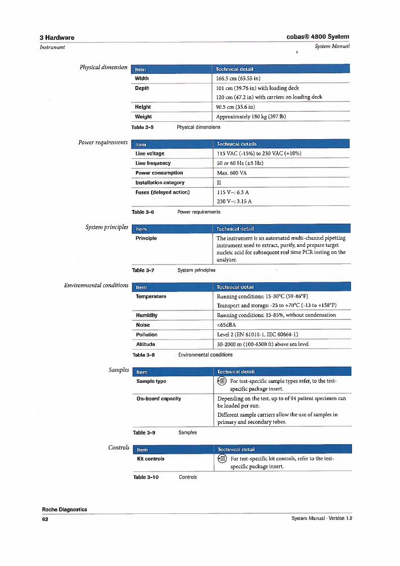
Table 3-5 Physical dimensions
Power requirernents
Systern principles
Environmental conditions
Item Technical details
Line voltage 115 VAC (-15%) to 230 VAC (+10%)
Line frequency 50 or 60 Hz (±5 Hz)
Power consumption Max. 600 VA
Installation category II
Fuses (delayed action) 115 V—: 6.3 A
230V—: 3.15A
Table 3-6 Power requirements
Item Technical detail
Principle The instrument is an automated multi-channel pipettinginstrument used to extract, purify, and prepare targetnucleic acid for subsequent real time PCR testing on theanalyzer.
Table 3—7 System principles
Item Technical detail
Temperature Running conditions: 15-30°C (59-86°F)
Transport and storage: -25 to ÷70°C (-13 to ÷158°F)
Humidity Running conditions: 15-85%, without condensation
Noise <65dBA
Pollution Level 2 (EN 61010-1, IEC 60664-1)
Altitude 30-2000 m (100-6500 ft) above sea level
Table 3—8 Environmental conditions
Roche Diagnosties
Saniples Item Technical detail
Sample type For test-specific sample types refer, to the test
specific package ïnsert.
On-board capacity Depending on the test, up to of 94 patient specimen canbe loaded per run.
Different sample carriers allow the use of samples inprimary and secondary tubes.
Table 3-9 Samples
Physical dirnension
Width
Depth
166.5 cm (65.55 in)
Height
Item Technical detail
Weight
101 cm (39.76 in) with loading deck
120 cm (47.2 in) with carriers on loading deck
90.5 cm (35.6 in)
Approximately 180 kg (397 ib)
Controls
Kit controls
Item Technical detail
Table 3-10 Controls
For test-specific kit controls, refer to the test
j specific package insert.
62 System Manual . Version 1.0
cobas® 4800 System 3 Hardware
Systenz Manual
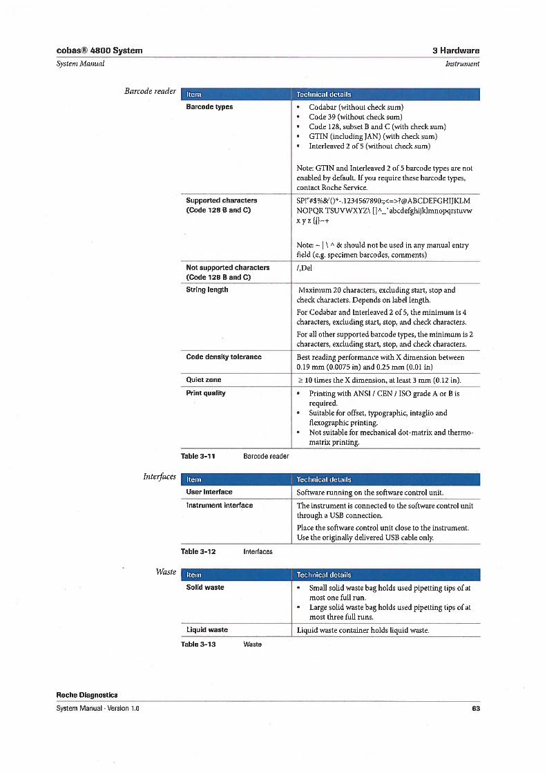
• Codabar (without check sum)• Code 39 (without check sum)• Code 128, subset B and C (with check sum)• GTIN (inciuding JAN) (with check sum)• Interleaved 2 of 5 (without check sum)
Instrument
Note: GTIN and Interleaved 2 of 5 barcode types are notenabled by default. 1f you require these barcode types,contact Roche Service.
Supported characters SP!#$%&O*. 1234567890:;<=>@ABCDEFGHIJKLM(Code 128 B and C) NOPQRTSUVWXYZ\ []A_’abcdefghijklmnopqrstuvw
xyz{}+
Note: \ A & should not be used in any manual entryfield (e.g. specimen barcodes, comments)
Not supporled characters /,Del(Code 128 B and C)
String length Maximum 20 characters, excluding start, stop andcheck characters. Depends on label length.
For Codabar and Interleaved 2 of 5, the minimum is 4characters, excluding start, stop, and check characters.
. For all other supported barcode types, the minimum is 2characters, excluding start, stop, and check characters.
Code density tolerance Best reading performance with X dimension between0.19 mm (0.0075 in) and 0.25 mm (0.01 in)
Quiet zone 10 times the X dimension, atleast 3 mm (0.12 in).
Print quality • Printing with ANSI / CEN / ISO grade A or B isrequired.
. Suitable for offset, typographic, intaglio andflexographic printing.
. Not suitable for mechanical dot-matrix and thermomatrix printing.
Table 3-11 Barcode reader
Interfaces Item Technical details
User interface Software running on the software control unit.
Instrument interface The instrument is connected to the software control unitthrough a USB connection.
Place the software control unit close to the instrument.Use the originally delivered USB cable only.
Table 3-12 Interfaces
Waste Item Technical details
Solid waste • Small solid waste bag holds used pipetting tips of atmost one full run.
. Large solid waste bag holds used pipetting tips of atmost three full runs.
Liquid waste Liquid waste container holds liquid waste.
Table 3-13 Waste
Roche Diagnostics
Barcode reader
Barcode types
Item Technical details
System Manual . Version 1.0 63
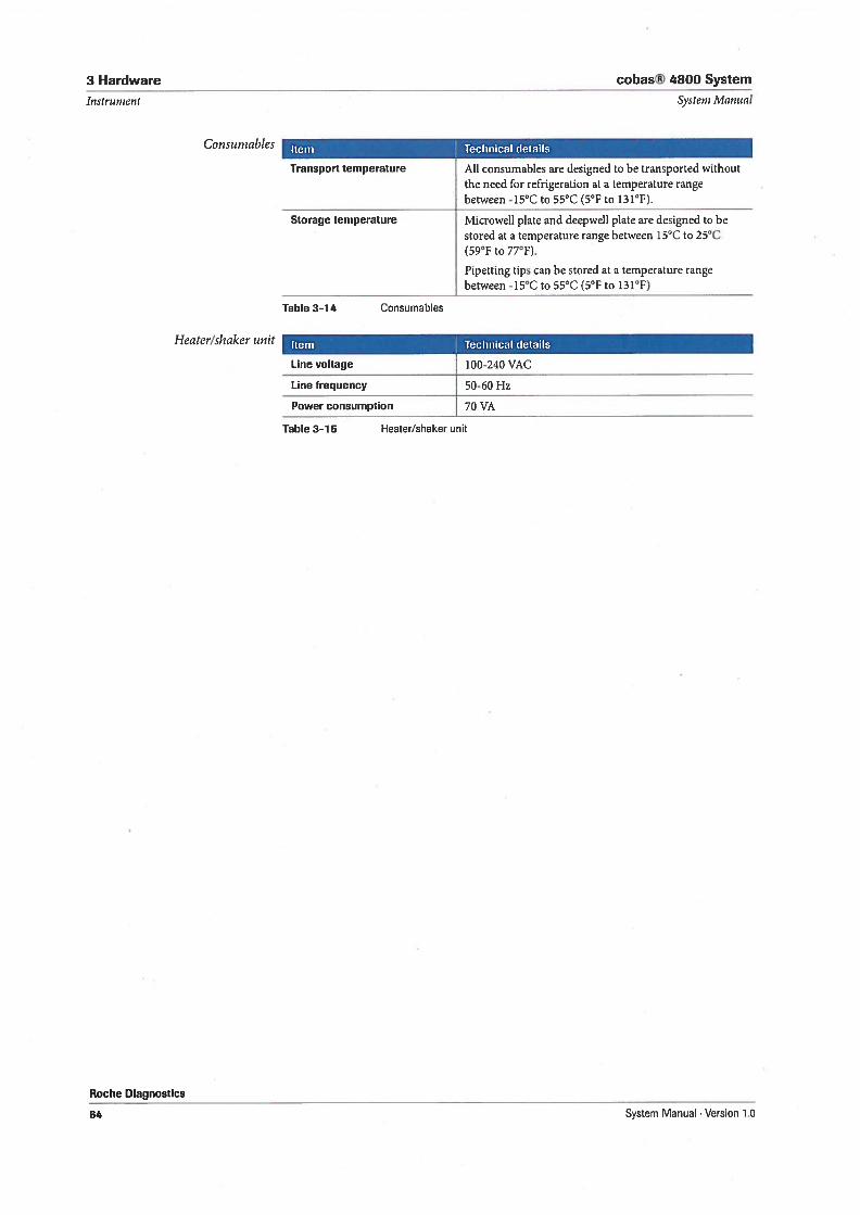
3 Hardware cobas® 4800 System
Instrument Systeni Manual
Consumables Item Technical details
Transport temperature All consumables are designed to be transported withoutthe need for refrigeration at a temperature rangebetween -15°C to 55°C (5°F to 131°F).
Storage temperature Microweil plate and deepwell plate are designed to bestored at a temperature range between 15°C to 25°C(59°F to 77°F).
Pipetting tips can be stored al a temperature rangebetween -15°C to 55°C (5°F to 131°F)
Table 3-14 Consumables
Heater/sizaker unit
Roche Diagnostics
64
Item Technical details
Line voltage 100-240 VAC
Line frequency 50-60 Hz
Power consumption 70 VA
Table 3-15 Heater/shaker unit
System Manual . Version 1.0
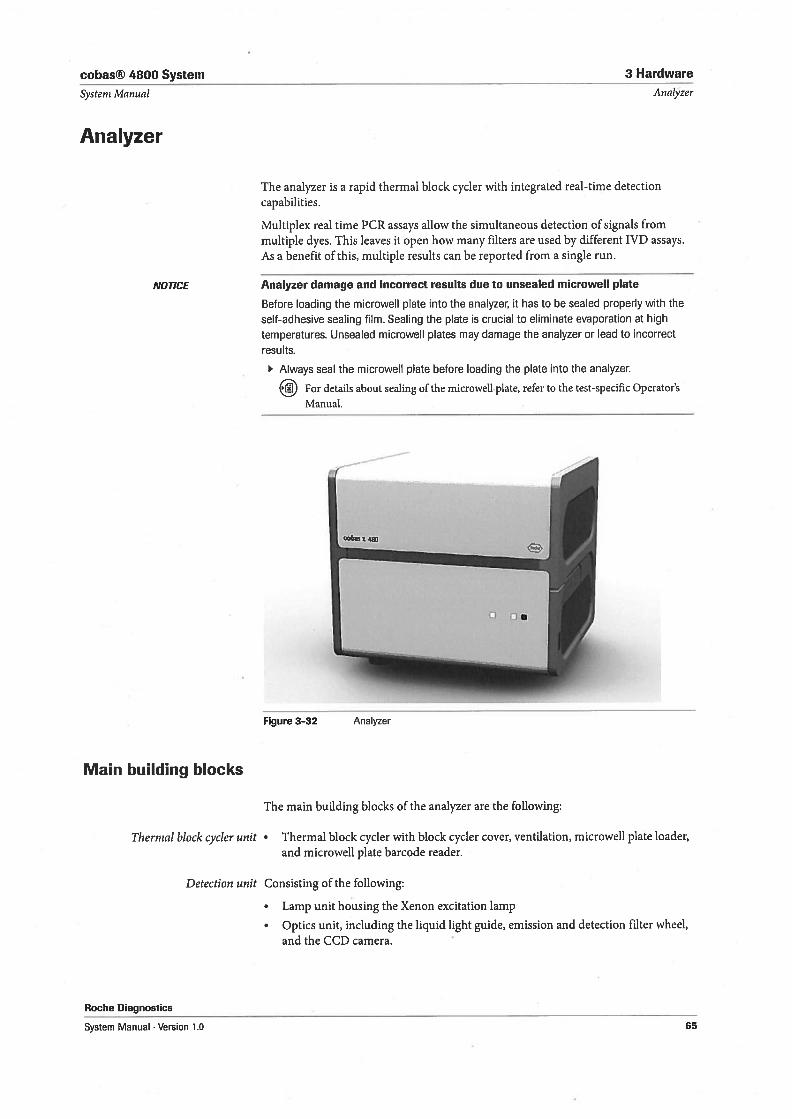
cobas® 4800 System 3 Hardware
Systern Manual
Analyzer
Analyzer
The analyzer is a rapid thermal block cycler with integrated real-time detectioncapabilities.
Multiplex real time PCR assays allow the simultaneous detection of signals fromrnultiple dyes. This leaves It open how many filters are used by different IVD assays.As a benefit of this, multiple resuits can be reported from a single run.
NOTICE
Main building blocks
Thermal block cycler unit
Analyzer damage and incorrect resuits due to unsealed microweil plate
Before loading the microweli plate into the analyzer, it has to be sealed properly with the
self-adhesive sealing film. Sealing the plate is crucial to eliminate evaporation at high
temperatures. Unsealed microwell plates may damage the analyzer or lead to incorrect
results.
Always seal the microweil plate before loading the plate into the analyzer.
For details about sealing of the microwell plate, refer to the test-specific Operator’s
Manual.
Figure 3-32 Analyzer
The main building blocks of the analyzer are the following:
• Thermal block cycler with block cycler cover, ventilation, microwell plate loader,and microweil plate barcode reader.
Roche Diagnostics
Detection unit Consisting of the following:
• Lamp unit housing the Xenon excitation lamp
• Optics unit, including the liquid light guide, emission and detection filter wheel,and the CCD camera.
System Manual . Version 1.0 65
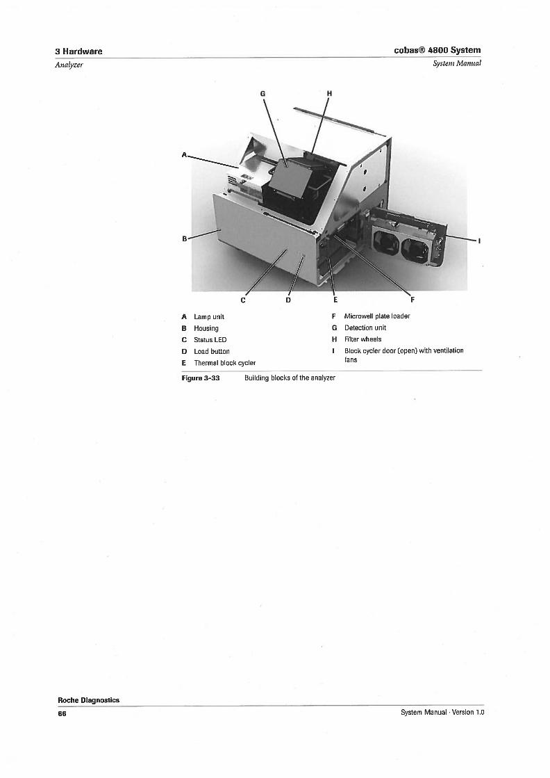
3 Hardware cobas® 4800 System
Analyzer Systern Manual
A Lamp unit
B Hausing
C Status LED
D Laad buttan
H Filter wheels
1 Black cycler daar (apen] with ventilation
H
BÇ
F Micrawell plate laader
G Detectian unit
E Thermal block cycler fans
Figure 3—33 Building blocks af the analyzer
Roche Diagnostics
66 System Manual . Versian 1.0
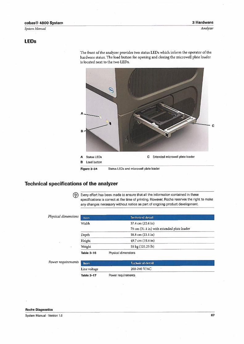
cobas® 4800 System 3 Hardware
Systern Manual
LEDs
Analyzer
The front of the analyzer provides two status LEDs which inform the operator of thehardware status. The bad button for opening and closing the microweil plate loaderis bocated next to the two LEDs.
A Status LEDs
B Load button
Figure 3-34 Status LEDs and microweil plate loader
Technical specifications of the analyzer
Every effort has been made to ensure that all the information contained in these
specifications is correct at the time of printing. However, Roche reserves the right to make
any changes necessary without notice as part of ongoing product development.
Physical di,nensions
Power requirernents
Item Technical detail
Width 57.4 cm (22.6 in)
79cm (3 1.1 in) with extended plate loader
Depth 58.8 cm (23.1 in)
Height 49.7 cm (19.6 in)
Weight 55kg (121.25 ib)
Table 3—16 Physical dimensions
Item Technical detail
Line voltage 200-240 V/AC
Roche Diagnostics
System Manual . Version 1.0
Table 3-17 Power requirements
1!.)
1
C Extended microweil plate loader
67
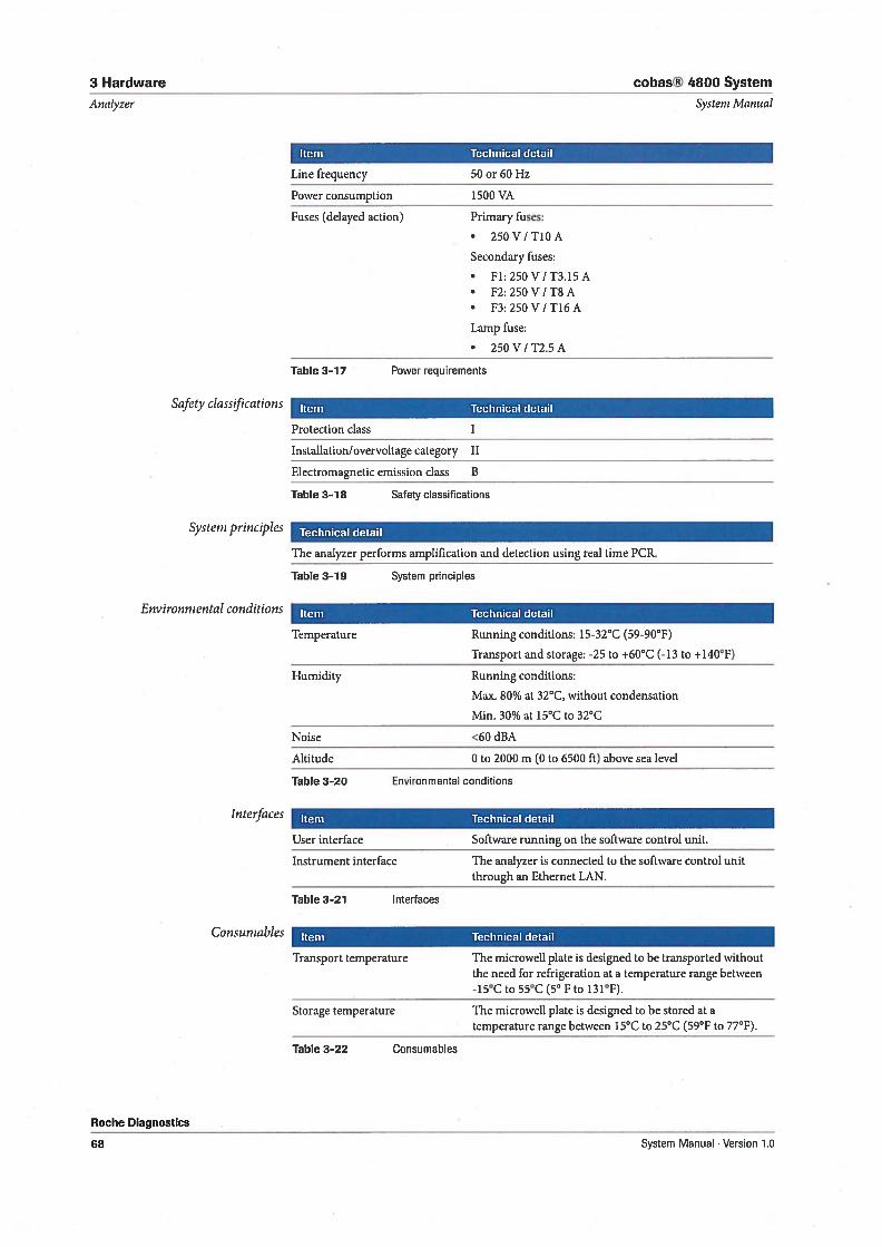
3 Hardware cobas® 4800 System
Analyzer Systern Manual
Item Technical detail
Line frequency 50 or 60 Hz
Power consumption 1500 VA
Fuses (delayed action) Primary fuses:
• 250V/TIOA
Secondary fuses:
• F1:250V/T3.15A• F2:250V/T8A• F3:250V/T16A
Lamp fuse:
• 250V/T2.5A
Table 3-17 Power requirements
Safrty classflcations
Systern principles
Environmental conditions
Interfaces
Consurnables
Roche Diagnostics
68
Item Technical detail
Protection class T
Installation/overvoltage category II
Electromagnetic emission class B
Table 3—18 Safety classifications
Technical detail
The analyzer performs amplification and detection using real time PCR.
Table 3-19 System principles
Item Technical detail
Temperature Running conditions: 15-32°C (59-90°F)
Transport and storage: -25 to ÷60°C (-13 to ÷140°F)
Humidity Running conditions:
Max. 80% at 32°C, without condensation
Min. 30% at 15°C to 32°C
Noise <60 dBA
Altitude 0 to 2000 m (0 to 6500 ft) above sea level
Table 3—20 Environmental conditions
Item Technical detail
User interface Software running on the software control unit.
Instrument interface The analyzer is connected to the software control unitthrough an Ethernet LAN.
Table 3-21 Interfaces
Item Technical detail
Transport temperature The microweil plate is designed to be transported withoutthe need for refrigeration at a temperature range between-15°C to 55°C (5°F to 131°F).
Storage temperature The microweli plate is designed to be stored at atemperature range between 15°C to 25°C (59°F to 77°F).
Table 3-22 Consuma bles
System Manual . Version 1.0
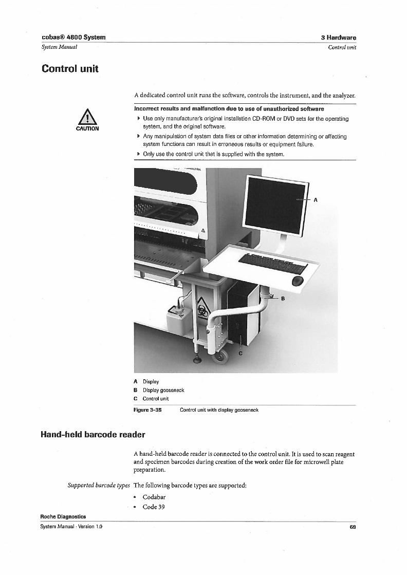
cobas® 4800 System
System Manual
Control unit
3 Hardware
Control unit
A dedicated control unit runs the software, controls the instrument, and the analyzer.
CAUTION
Hand-held barcode reader
Incorrect resuits and malfunction due to use of unauthorized software
Use only manufacturers original installation CD-ROM or DVD sets for the operatingsystem, and the original software.
Any manipulation of system data files or other information determining or affectingsystem functions can result in erroneous results or equipment failure.
Only use the control unit that is supplied with the system.
Control unit with display gooseneck
A
A hand-held barcode reader is connected to the control unit. It is used to scan reagentand specimen barcodes during creation of the vork order file for microweli platepreparation.
Supported barcode types
Roche Diagnostics
System Manual . Version 1.0
The following barcode types are supported:
• Codabar
• Code 39
1A Display
B Display gooseneck
C Control unit
Figure 3-35
69
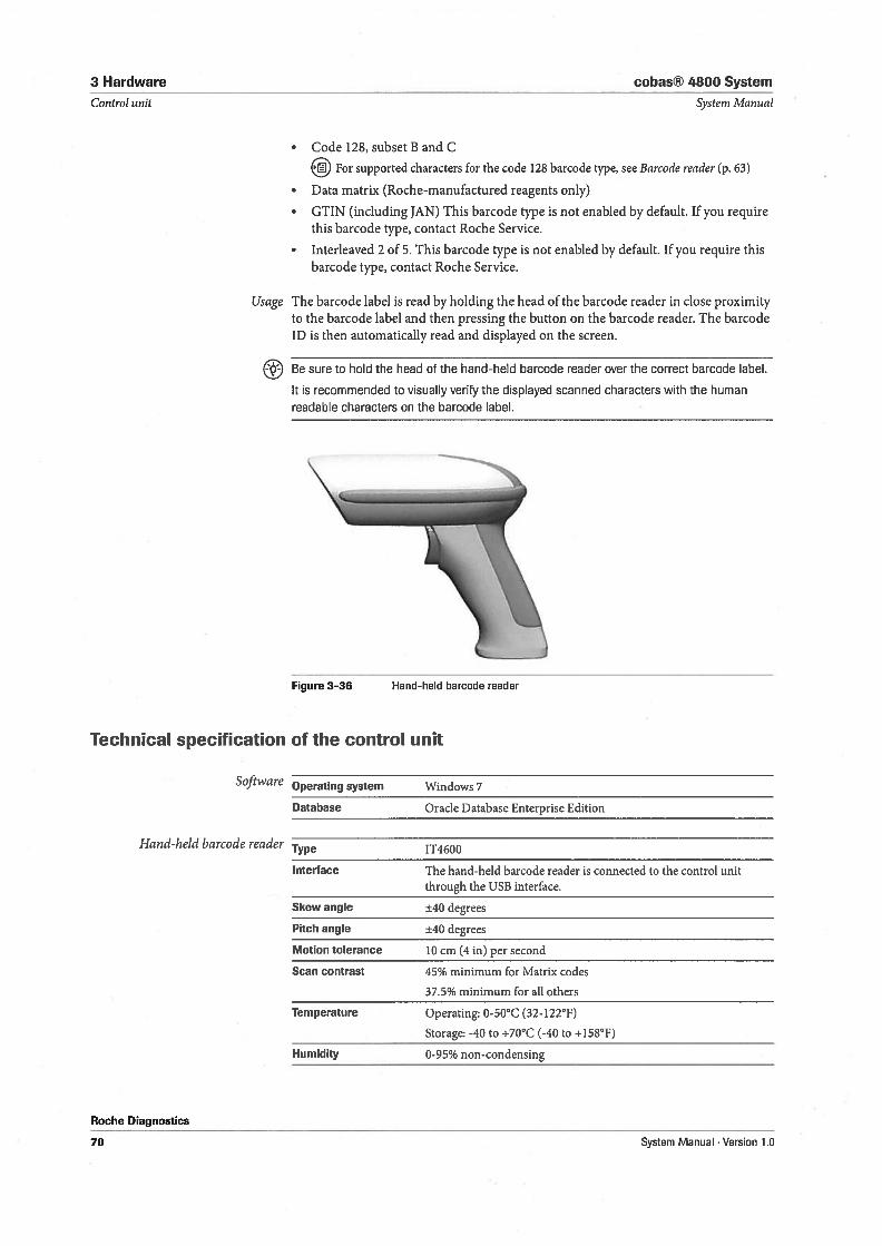
3 Hardware
Control unit
cobas® 4800 System
Systenz Manual
• Code 128, subset B and C
€iEjl For supported characters for the code 128 barcode type, see Barcode reader (p. 63)
• Data matrix (Roche-manufactured reagents only)
• GTIN (inciuding JAN) This barcode type is not enabled by default. 1f you requirethis barcode type, contact Roche Service.
• Interleaved 2 of 5. This barcode type is not enabled by default. 1f you require thisbarcode type, contact Roche Service.
Usage The barcode label is read by holding the head of the barcode reader in close proximityto the barcode label and then pressing the button on the barcode reader. The barcodeID is then automatically read and displayed on the screen.
Be sure to hold the head of the hand-held barcode reader over the correct barcode label.
It is recommended to visually verify the displayed scanned characters with the human
readable characters on the barcode label.
Figure 3-36 Hand-held barcode reader
Technical specification of the control unit
Software Operating system Windows 7
Database Oracle Database Enterprise Edition
Hand-held barcode reader Type 1T4600
Interface The hand-held barcode reader is connected to the control unitthrough the USB interface.
Skew angle ±40 degrees
Pitch angle ±40 degrees
Motion tolerance 10 cm (4 in) per second
Scan contrast 45% minimum for Matrix codes
3 7.5% minimum for all others
Temperature Operating: 0-50°C (32-122°F)
Storage: -40 to +70°C (-40 to +158°F)
Humidity 0-95% non-condensing
Roche Diagnostics
70 System Manual Version 1.0
cobas® 4800 System 4 Software
Table of contents Systern Manual
Software
In this chapter the software basics are explained.
In this chapter Chapter LI
Basic software elements 73Colors 74
Tabs 74
Buttons 75
Lists 76Organizing lists 76Sort by column 77Column header context menu 77Displaying and hiding columns 77Filter drop-down list 78
Custom AutoFilter 78Managing filters and advanced filtering 79
Tool tips 79Wizard 80
Database 81Audit trail 81
Roche Diagnostics
System Manual . Version 1.0 71

4 Software cobas® 4800 System
Table of contents System Manual
Roche Diagnostics
72 System Manual Version 1.0
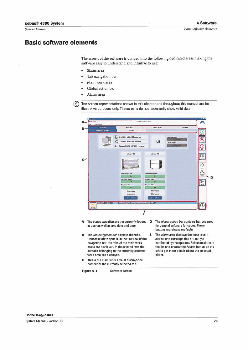
cobas® 4800 System 4 Software
System Manual
Basic software elements
Basic software elenzents
The screen of the software is divided into the following dedicated areas making thesoftware easy to understarid and intuitive to use:
Status area
• Tab navigation bar
• Main work area
• Global action bar
Alarm area
The screen representations shown in this chapter and throughout this manual are for
illustrative purposes only. The screens do not necessarily show valid data.
— ‘ 1C? C- 214106 alZSflQB 4aw
- ‘0 uwat 0,9 00 al Ufl 00 Wet $6CC
A The status area displays the currently logged Din user as well as and date and time.
B The tab navigation bar displays the tabs.Choose a tab to open t. In the first row of thenavigation bar, the tabs of the main workareas are displayed. In the second row, thesubtabs belonging to the currently selectedwork area are displayed.
C This is the main work area. It displays thecontent of the currently selected tab.
Figure 4-1 Software screen
The global action bar contains buttons usedfor general software functions. Thesebuttons are always available.
E The alarm area displays the most recentalarms and warnings that are not yetconfirmed by the operator. Select an alarm inthe list and choose the Alarm button on theleft to get more details about the selectedalarm.
Roche Diagnostics
A[
B — Ft.l..,• R*sats Messagos U1lI,t,es
0061010
LIS
,a0412406
LJ LJ
-
6
a
100 69e
rwl69t9e —
N0.vaIlaOe
00
/E
.,
System Manual . Version 1.0 73
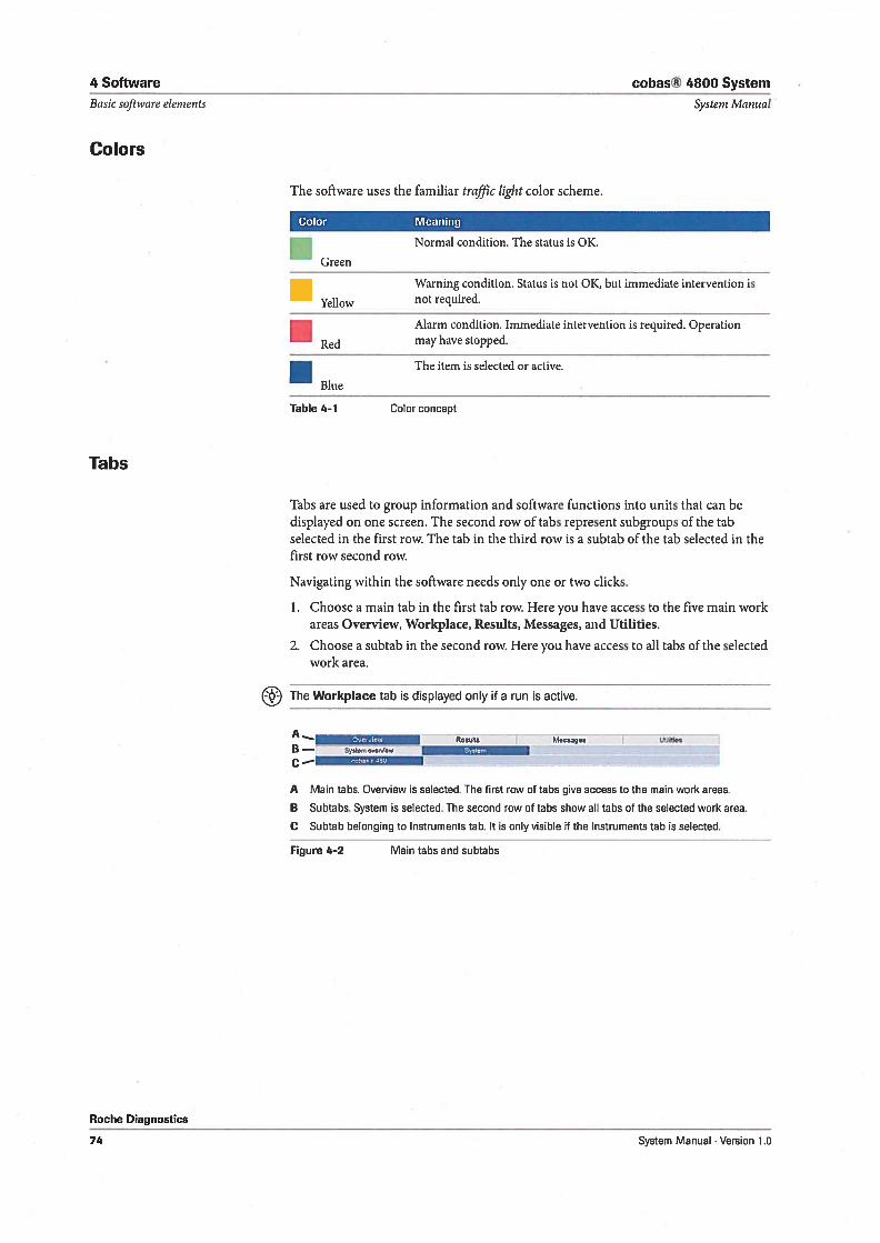
4 Software cobas® 4800 System
Basic software elements Systenz Manual
Colors
The software uses the familiar traffic light color scheme.
Color Meaning
S Normal condition. The status is 0K.
Green
I Warning condition. Status is not 0K, but immediate intervention is
Yellow not required.
. Alarm condition. Immediate intervention is required. Operation
Red may have stopped.
S The item is selected or active.
Blue
Table 4-1 Color concept
Tabs
Tabs are used to group information and software functions into units that can bedisplayed on one screen. The second row of tabs represent subgroups of the tabselected in the first row. The tab in the third row is a subtab of the tab selected in thefirst row second row.
Navigating within the software needs only one or two clicks.
L Choose a main tab in the first tab row. Here you have access to the five main workareas Overview, Workpiace, Resuits, Messages, and Utilities.
2. Choose a subtab in the second row. Here you have access to all tabs of the selectedwork area.
The Workpiace tab is displayed only if a run is active.
A1’TPi..’ Resuits Messges Ul5ttes
B— ste,,
C—
A Main tabs. Overview is selected. The first row of tabs give access to the main work areas.
B Subtabs. System is selected. The second row of tabs show all tabs of the selected work area.
C Subtab belonging to lnstruments tab. It is only visible t the Instruments tab is selected.
Figure 4-2 Main tabs and subtabs
Roche Diagnostics
74 System Manual . Version 1.0
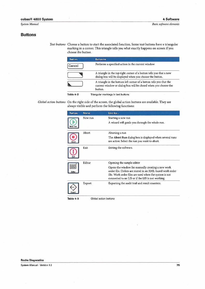
cobas® 4800 System 4 Software
Systern Manual Basic software elerneuts
Buttons
Text buttons Choose a button to start the associated function. Some text buttons have a triangularmarking in a corner. This triangle telis you what exactly happens on screen if youchoose the button.
Button Behavior
r 1 Performs a specified action in the current windowCanceI j
A triangle in the top right corner of a button telis you that a newL J dialog box will be displayed when you choose the button.
r 1 A triangle in the bottom left corner of a button Leus you that theL J current window or dialog box will be closed when you choose the
button.
Table 4—2 Triangular markings in text buttons
Global action buttons On the right side of the screen, the global action buttons are available. They arealways visible and perform the following functions:
Button Name Use for...
. New run Starting a new run
[ ij A wizard will guide you through the whole run.
Abort Aborting a run
U The Abort Run dialog box is displayed when several runs
Abart are active. Select the run you want to abort.
ï 1Exit Exiting the software.
Exit
Editor Opening the sample editor
ilihi Opens the window for manually creating a new work
EJ order file. Orders are stored in an XML-based work orderfile. Work order files are used when the system is notconnected to an LIS or if the LIS is not working.
Export Exporting the audit trail and result counters.
‘€1Export
Table 4-3 Global action buttons
Roche Diagnostics
System Manual . Version 1.0 75
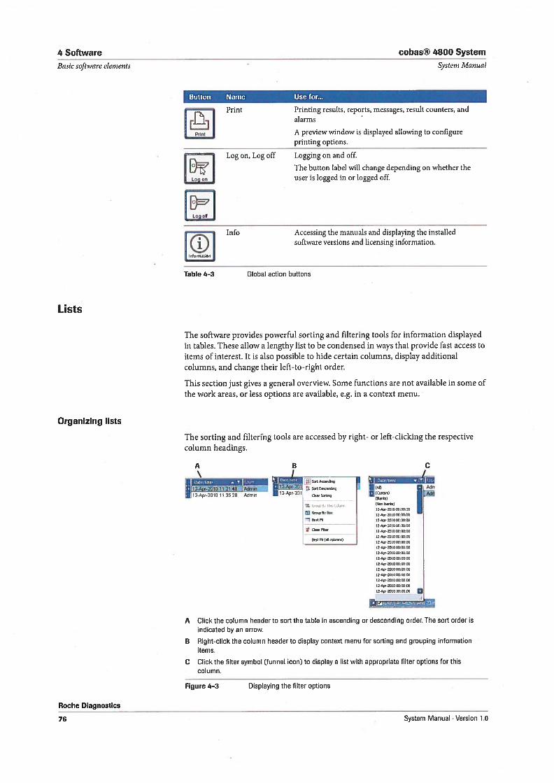
4 Software cobas® 4800 System
Basic software elements Systern Alanual
Button Name Use for...
Print Printing results, reports, messages, result counters, and
L_J alarms
A preview window is displayed allowing to configureprinting options.
Log on, Log off Logging on and off.
[)‘ The button label will change depending on whether the
Log user is logged in or logged off.
IEILog oS
Info Accessing the manuals and displaying the installedsoftware versions and licensing information.
Table 4-3 Global action buttons
Lists
The software provides powerful sorting and filtering tools for information displayedin tables. These allow a lengthy list to be condensed in ways that provide fast access toitems of interest. It is also possible to hide certain columns, display additionalcolumns, and change their left-to-right order.
This section just gives a general overview. Some functions are not available in some ofthe work areas, or less options are available, eg. in a context menu.
Organizing Iists
The sorting and filtering tools are accessed by right- or left-clicking the respectivecolumn headings.
1
_________
aliî 201fl 11 2149 Admm D112 AOr 201 s DOO,Ç 1 1 (J) Ad
•12.Açr.2010 11 352B Adoin 112Apr-201, O(’)5 (N880)
tz-gc,.lo yJ-xxG0O 12-40,201080 80)2
12-40, 2010 8080x
12-40,20108080:80
12-440-21080:80)2
400,
12-44,201000:00.80
12-4,201280:80.80
1240201380:80.00
12.44,201080:80:80
80:80:80
IZD40-2010 80:80:00
12-40-201080:80:80
10-40-201001-0080
12-440-201080:0080
C..’iit.
A Click the column header to sort the table in ascending or descending order. The sort order isindicated by an arrow.
B Right-click the column header to display context menu for sorting and grouping informationitems.
C Click the filter symbol (funnel icon) to display a list with appropriate filter options for thiscolumn.
Figure 4-3 Displaying the filter options
Roche Diagnostics
76 System Manual . Version 1.0
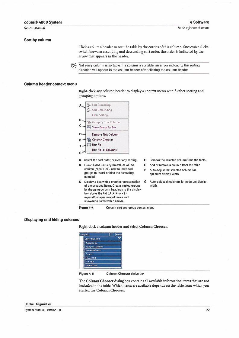
cobas® 4800 System 4 Software
Systeni Pvlanual
Sort by column
Basic software elements
Click a column header to sort the table by the entries of this column. Successive clicksswitch between ascending and descending sort order, the order is indicated by thearrow that appears in the header.
Column header context menu
Not every column is sortable. 1f a column is sortable, en arrow indicating the sorting
direction will appear in the column header after clicking the column header.
Right-click any column header to display a context menu with further sorting andgrouping options.
A
C
0 — Rmove This Column
E — Column Chooser
—BestFit
Best Fit (all columns)G
A Select the sort order, or dear any sorting.
B Group listed items by the values of thiscolumn (dick + or - next to individualgroups to reveal or hide the items theycontain).
C Display a box with a graphic representationof the grouped items. Create nested groupsby dragging column headings to the displaybox above the list (dick + or - toexpand/collapse nested levels andshow/hide items within a level.
Remove the selected column from the table.
Add or remove a column from the table
Auto-adjust the selected column foroptimum display width.
G Auto-adjust all columns for optimum displaywidth.
Displaying and hiding columns
Figure 4-4 Column sort and group context menu
Roche Diagnostics
Right-click a column header and select Column Chooser.
Figure 4-5 Column Chooser dialog box
The Column Chooser dialog box contains all available information items that are notincluded in the table. Which items are available depends on the table from which youstarted the Column Chooser.
SortAscending
Sc’rt Descending
f’lear Scrtinq
Group Bylhis Column
Show Group By Box
D
E
F
System Manual Version 1.0 77
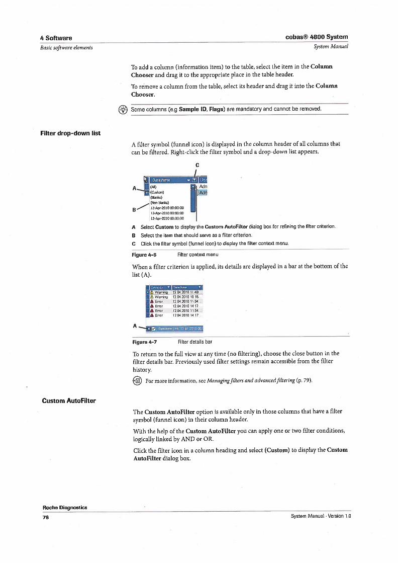
4 Software cobas® 4800 System
Basic software elernents Systern Manual
To add a column (information item) to the table, select the item in the ColumnChooser and drag it to the appropriate place in the table header.
To remove a column from the table, select its header and drag it into the ColunmChooser.
Some columns (e.g Sample ID, Flags) are mandatory and cannot be removed.
Filter drop-down list
A filter symbol (funnel icon) is displayed in the column header of all columns thatcan be filtered. Right-click the filter symbol and a drop-down list appears.
c1
Date/time 1!)A 1(011) Adn
(Custoro) Âdn(Oonko)(Non btonlçs)12-Apr-2010 00:00:00
12-Apr-2010 00:00:00
12-Apr-2010 00:00:00
A Select Custom to display the Custom AutoFilter dialog box for reflning the filter criterion.
B Select the item that should serve as a filter criterion.
C Click the filter symbol (tunnel icon) to display the filter context menu.
Figure 4—6 Filter context menu
When a filter criterion is applied, its details are displayed in a bar at the bottom of thelist (A).
1jaJtrr:.-a
I 1 Warning 1204.2010 1010.
ItError 120420101154
IA Error 120420101417
Iterror 1204,20101154
Ikerror 120420101417
x 5
Figure 4-7 Alter details bar
To return to the full view at any time (no filtering), choose the close button in thefilter details bar. Prevlously used filter settings remain accessible from the filterhistory.
For more information, see Managingfilters and advancedfiltering (p. 79).
Custom AutoFilter
The Custom AutoFilter option is available only in those columns that have a filtersymbol (funnel icon) in their column header.
With the help of the Custom AutoFilter you can apply one or two filter conditions,logically linked by AND or OR.
Click the filter icon in a column heading and select (Custom) to display the CustomAutoFilter dialog box.
Roche Diagnostics
78 System Manual - Version 1.0
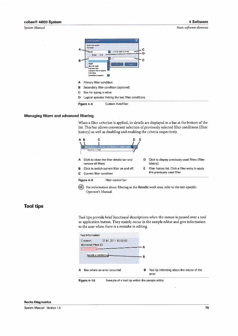
cobas® 4800 System 4 Software
Systern Manual Basic software elernents
Figure 4-8
Managing filters and advanced filtering
A Primary filter condition
B Secondary filter condition (optional)
C Box for typing a value
D Logical operator linking the two filter conditions
Custom AutoFilter
When a filter criterion is applied, its details are displayed in a bar at the bottom of thelist. This bar allows convenient selection of previously selected filter conditions (filterhistory) as well as disabling and enabling the criteria respectively.
Tool tips
AB C DE\ 1 II
A Click to close the filter details bar andremove all filters.
B Click to switch current filter on and off.
C Current filter condition
Figure 4-9 Filter control bar
For information about filtering in the Resuits work area, refer to the test-specificOperator’s Manual.
Tool tips provide brief functional descriptions when the mouse is paused over a toolor application button. They mainly occur in the sample editor and give informationto the user when there is a mistake in editing.
Test Information
Creation 2701.2011 15:53:50
Microweli Plate ID
Oarcode is mandator_L__B
A Box where an error occurred fl Tool tip informing about the nature of theerror
Roche Diagnostics
System Manual . Version 1.0
Figure 4—10 Example of a tool tip within the sample editor
[SeJentyj <Fatar
D Click to display previously used filters [filterlistory].
E Filter history list: Click a filter entry to applythis prevlously used filter.
79
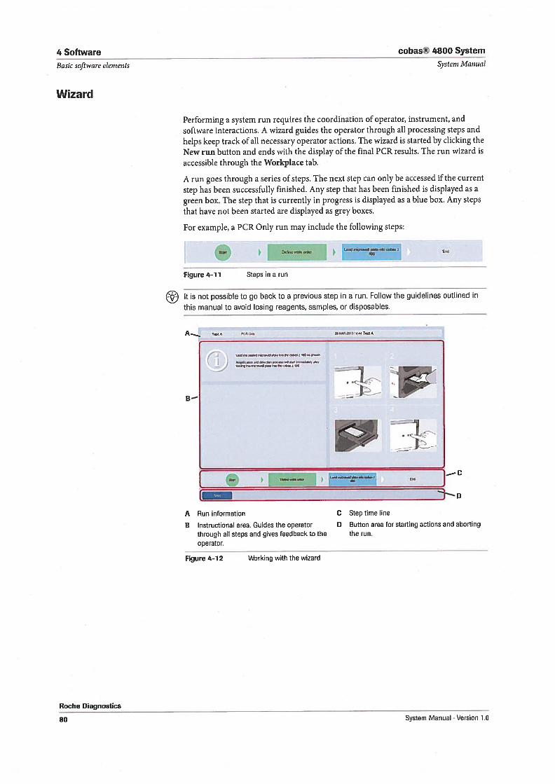
4 Software cobas® 4800 System
Performing a system run requires the coordination of operator, instrument, andsoftware interactions. A wizard guides the operator through all processing steps andheips keep track of all necessary operator actions. The wizard is started by clicking theNew run button and ends with the display of the final PCR results. The run wizard isaccessible through the Workpiace tab.
A run goes through a series of steps. The next step can onlybe accessed if the currentstep has been successfully finished. Any step that has been finished is displayed as agreen box. The step that is currently in progress is displayed as a blue box. Any stepsthat have not been started are displayed as grey boxes.
For example, a PCR Only run may include the following steps:
I Lond
Figure 4—11 Steps in a run
It is not possible to go back to a previous step in a run. Follow the guidelines outlined in
this manual to avoid losing reagents, samples, or disposables.
A Run information
B Instructional area. Guides the operatorthrough all steps and gives feedback to theoperator.
Figure 4—12 Working with the wizard
D Button area for starting actions and abortingthe run.
Roche Diagnostics
Basic software elemeats
Wizard
Systeni Manual
End
24 LtARa,, 4447.444
— c
D
C Step time line
80 System Manual . Version 1.0
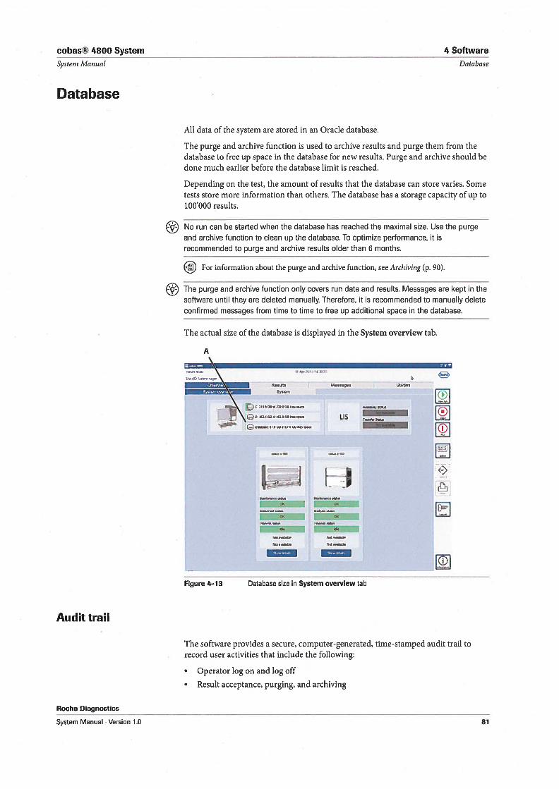
cobas® 4800 System
System Manual
Database
All data of the system are stored in an Oracle database.
4 Software
Database
Audit trail
Roche Diagnostics
System Manual Version 1.0
The purge and archive function is used to archive resuits and purge them from thedatabase to free up space in the database for new resuits. Purge and archive should bedone much earlier before the database limit is reached.
Depending on the test, the amount of resuits that the database can store varies. Sometests store more information than others. The database has a storage capacity of up to100000 resuits.
No run can be started when the database has reached the maximal size. Use the purgeand archive function to clean up the database. To optimize performance, It isrecommended to purge and archive results older than 6 months.
For information about the purge and archive function, see Archiving (p. 90).
The purge and archive function only covers run data and results. Messages are kept in thesoftware until they are deleted manually. Therefore, it is recommended to manually deleteconfirmed messages from time to time to free up additional space in the database.
The actual size of the database is displayed in the System overview tab.
jr Li
‘—4,4—,—
‘-4,—
Figure 4-13 Database size in System overview tab
The software provides a secure, computer-generated, time-stamped audit trail torecord user activities that inciude the fo11owing
• Operator log on and log off
• Result acceptance, purging, and archiving
A
(TJ 0.4621 GO 01462606 6.»400 LIS
0
.
fl46 ,.sil.bIe
81
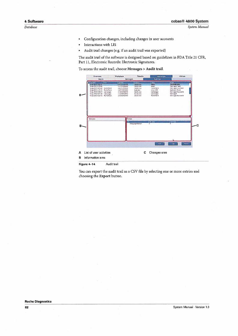
4 Software
Database
cobas® 4800 System
Systeni Manual
• Configuration changes, inciuding changes in user accounts
• Interactions with LIS
• Audit trail changes (e.g. ifan audit trail was exported)
The audit trail of the software is designed based on guidelines in FDA Title 21 CFR,Part 11, Electronic Records: Electronic Signatures.
To access the audit trail, choose Messages > Audit trail.
OVr3W Workp!22e Reufts Utlidies
1
ki4,o.4.,,
—r—W,9{,9.3&d203f2, 0
--
Roche Diagnostics
A List of user activities
B Information area
Figure 4-14 Audittrail
C Changes area
You can export the audit trail as a CSV file by selecting one or more entries andchoosing the Export button.
B-
1rI..93041h1 1 14 01 40 420tfl 34.1 dI 011204004
fl23 3313147131 fl01..C34.k .432320030004
11.23,2013122012 t04o,r, 44C2C018501034
lldç,.2013 122449 043330334. o4.3200I8000JIlI.Oo,.?fl13122445 3001,4033% 44.C2031203100
13130403
3,33 0.940 344 33 $00
0,4. 04937
0,,, 0333.. 333 04, $10
B—...,4 — c
82 System Manual . Version 1.0
Configuration
5 Configuration 85

cobas® 4800 System 5 Configuration
Table of contents Systern J’vianual
Configuration
In this chapter the configuration of the system and the export of support data isdescribed.
In this chapter Chapter II
Configuration 87
System settings 87
Reporting 88
Tests 89
Archiving 90
User management 92
Password management 92
Changing a password 92
User account management 93
Creating user accounts 93
Changing user accounts 95
Deleting user accounts 95
Unlocking user accounts 95
Rules 95
Account rules 96
Password rules 96
Exporting support data 97
Result counters 98
Roche fliagnostics
System Manual Version 1.0 85
5 Configuration cobas® 4800 System
Table of contents Systeni Manual
Roche Diagnostics
86 System Manual . Version 1.0
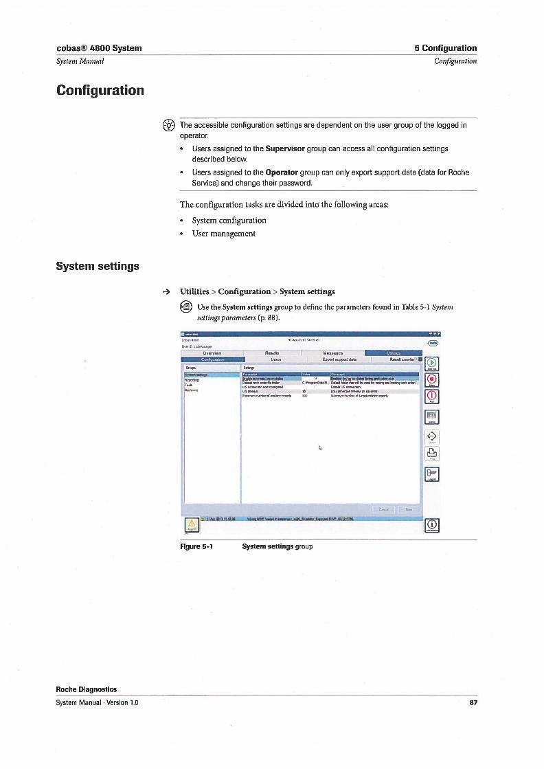
cobas® 4800 System 5 Configuration
Systern Manual Configuration
Configuration
The accessible configuration settings are dependent on the user group of the logged inoperator.
• Users assigned to the Supervisor group can access all configuration settingsdescribed below.
• Users assigned to the Operator group can only export support data (data for RocheService) and change their password.
The configuration tasks are divided into the following areas:
• System configuration
• User management
System settings
Utilities> Configuration> System settings
Use the System settings group to define the parameters found in Table 5-1 Systern
settingspararneters (p. 88).
411101 II 4 111 11 14 1511 49
1144110 LOO 144O1
Ove,v0w Resu4ts Messagos Il.rwws
_____________________
Usors EsporO Oopport dato R00rstor I [5- L=J
rjiIr soaoo.orw. 010 ,00o0 ar 40, sporrso..saldalr
1115 44* 044orllpsOd r bLlS401orertr*n
11150000* 40 s4Wior500orr.004050 ‘s- *olwlrflal015qo0rT,rWolO 500 MMrortor lig .04 pr,tlonr 000110
€0
El
Figure 5-1 System settings group
Roche Diagnostics
System Manual . Version 1.0 87
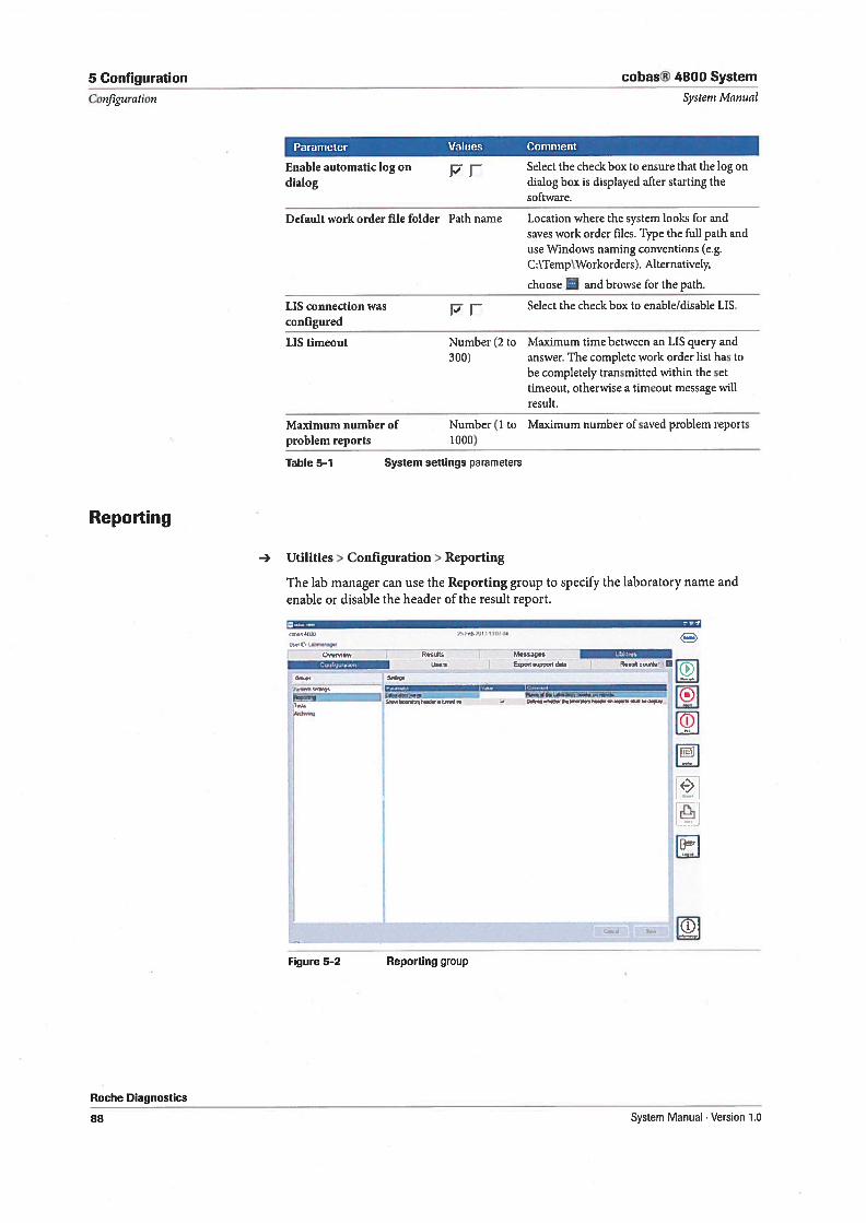
S Configuration cobas® 4800 System
Configuration
Reporting
Systent Manual
Parameter Values Comment
Select the check box to ensure that the log ondialog box is displayed after starting thesoftware.
-, Utilities > Configuration > Reporting
The lab manager can use the Reporting group to specify the laboratory name andenable or disable the header of the result report.
Ow,vrfw
_________
u
- L1... —:Z:SIwOflotyIflIU,Ifl,
Figure 5-2 Reporting group
Msssages bir4
0Det.ayt*Odfl,NIflflk9by
Roche Diagnostics
Enable automatic log on p- rdialog
Default vork order file folder Path name Location where the system looks for andsaves ivork order files. Type the full path anduse Windows naming conventions (e.g.C:\Temp\Workorders). Alternatively,
choose and browse for the path.
LIS connection was f7 F Select the check box to enable/disable LIS.configured
LIS timeout Number (2 to Maximum time between an LIS query and300) answer. The complete work order list has to
be completely transmitted within the settimeout, otherwise a timeout message willresult.
Maximum number of Number (1 to Maximum number of saved problem reportsproblem reports 1000)
Table 5-1 System settings parameters
88 System Manual . Version 1.0
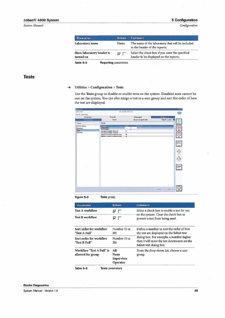
cobas® 4800 System 5 Configuration
Parameter Values Comment
Laboratory name Name The name of the laboratory that will be inciudedin the header of the reports.
Show Jaboratory header is p r Select the check box if you want the specifiedturned on header to be displayed on the reports.
Utilities> Configuration > Tests
Use the Tests group to disable or enable tests on the system. Disabled tests cannot berun on the system. You can also assign a test to a user group and sort the order of howthe test are displayed.
OtA,411(R) ?$eb-7flCI tUit ,I
U,.ID
Ove4viW •l R,its
3ttI*O
1 - -
Epot1 tippot d{ Rt S
Figure 5-3 Tests group
Parameter Values Comment
Test A workflow p r Select a check box to enable a test for use0fl the system. Clear the check box to
Test B workflow p F prevent a test from being used.
Sort order for workflow Number (0 to Define a number to sort the order of how‘Test A Full” 20) the test are displayed on the Select test
Sort order for workflow Number (0 to dialog box. For example, a number higher
“Test B Full” 20) than 0 will more the test downwards on theSelect test dialog box.
Workflow “Test A Full” is All From the drop-down list, choose a userallowed for group None group.
SupervisorOperator
Table 5-3 Tests parameters
Roche Diagnostics
System Manual . Version 1.0
Systern Manual
Tests
Configuration
Table 5-2 Reporting parameters
89
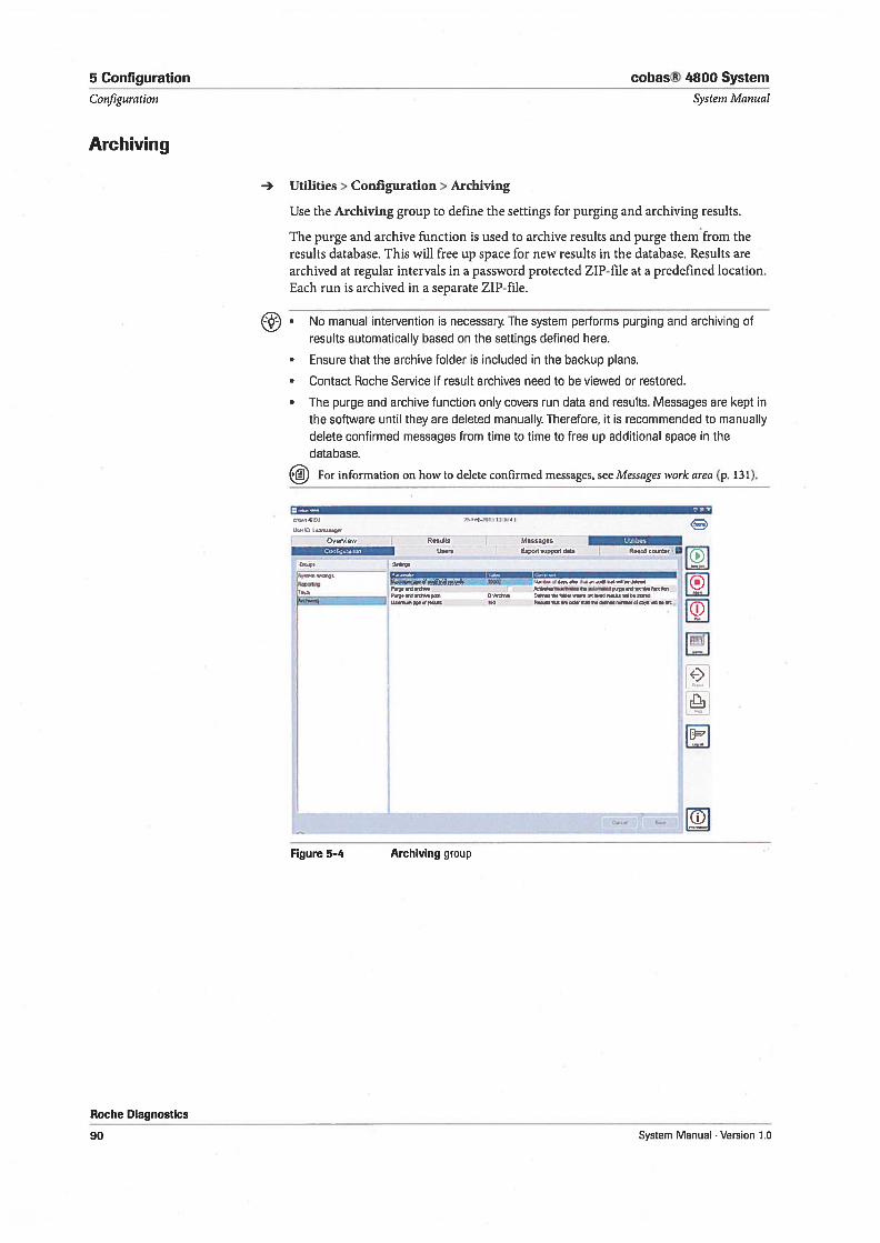
5 Configuration cobas® 4800 System
Configuration System Manual
Archiving
- Utilities> Configuration > Archiving
Use the Archiving group to define the settings for purging and archiving resuits.
The purge and archive function is used to archive resuits and purge themfrom theresuits database. This will free up space for new resuits in the database. Resuits arearchived at regular intervals in a password protected ZIP-file at a predefined location.Each run is archived in a separate ZIP-file.
• No manual intervention is necessary. The system performs purging and archiving ofresuits automatically based on the settings defined here.
• Ensure that the archive folder is inciuded in the backup plans.
• Contact Roche Service if result archives need to be viewed or restored.
• The purge and archive function only covers run data and resuits. Messages are kept inthe software until they are deleted manually Therefore, it is recommended to manuallydelete confirmed messages from time to time to free up additional space in thedatabase.
For information on how to delete confirmed messages, see Messages work area (p. 131).
,rrn41
Lh.,D
Overview Resuits Messages 10.103
___________________
Usurs Export support dsta Rosult 000310 a
54pR. su0..r03ro o0a f5Pifge 1.0 sOlo. 0300100.xsuOoamaedlofld ntiwh,0000
OWOx.e 000,loOei3xrxa,cOecuSr000ecflO.1 Mat,.n,,ç,Oreoss 110 RW000,zV OiOSrmr000efr,e0P.0,t,r0r0,YÇwrlOeot
Figure 5-4 Archiving group
Roche Diagnostics
90 System Manual . Version 1.0
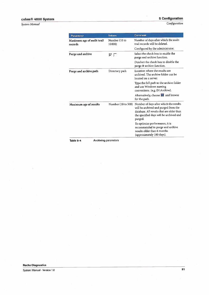
cobas® 4800 System 5 Configuration
System Manual CoJ/iguration
Parameter Values Comment
Maximum age of audit trail Number (10 to Number of days after which the audit
records 10000) trail records will be deleted.
Configured by the administrator.
Purge and archive p j’ Select the check box to enable thepurge and archive function.
Deselect the check box to disable thepurge & archive function.
Purge and archive path Directory path Location where the resuits arearchived. The archive folder can belocated on a server.
Type the full path to the archive folderand use Windows namingconventions. (e.g. D:\Archive)
Allernatively, choose and browsefor the path.
Maximum age of results Number (10 to 500) Number of days after which the resuitswill be archived and purged from thedatabase. All results that are older thanthe specified days will be archived andpurged.
To optimize performance, it isrecommended to purge and archiveresults older than 6 months(approximately 180 days).
Table 5-4 Archiving parameters
Roche Diagnostics
System Manual Version 1.0 91
5 Configuration cobas® 4800 System
User management System lt’fanual
User management
Utilities> Users
There are three groups of functions available for managing users:
• Changing passwords
• Managing user accounts
• Setting up rules for passwords and user accounts
• Only users that are assigned as Supervisor can manage users and can set up rules for
passwords and user accounts.
• Users assigned as Operator can change their password only.
• Keep user access information on a secure place and do not make t public to prevent
unauthorized access to the system.
Password management
The initial password is defined during set up of a user account.
For more information, see Creating user accounts (p. 93).
Changing a password
Any user can change their password. Lab managers can change the passwords of allusers. The password must follow the password rules that are defined in the software.
For more information, see Password rules (p. 96).
To change the password
1 Choose Utilities > Users > Change password.
The Change password dialog box is displayed.
2 In the Old password box, type the current password.
3 In the New password box, type the new password.
4 In the Repeat new password box, type the new password again.
5 Choose the 0K button.
To change the password of another user
1 Choose Utilities > Users.
2 Select a user in the list.
3 Choose the Reset password button.
4 In the Password box, type the new password.
5 In the Repeat password box, type the new password again.
6 Choose the Apply button.
Roche Diagnostics
92 System Manual . Version 1.0
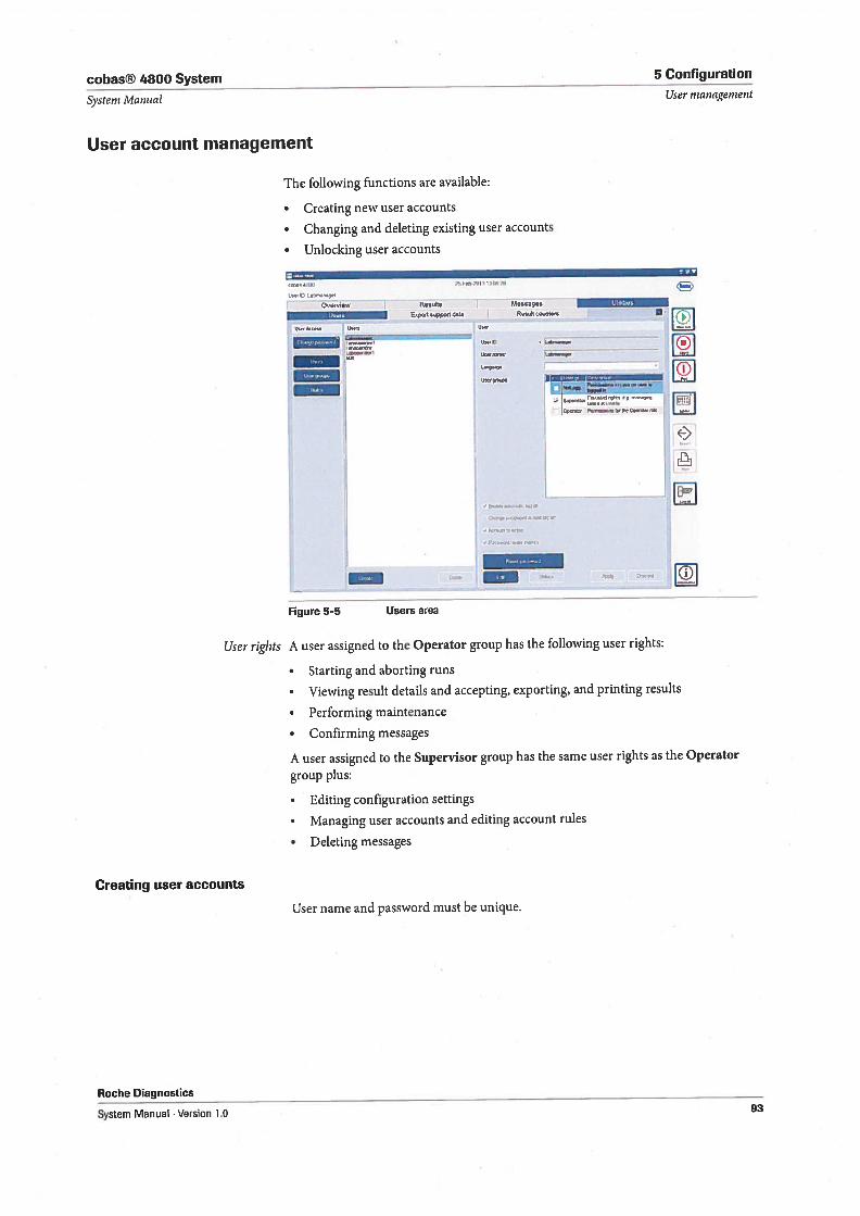
cobas® 4800 System 5 Cunfiguration
System ivlanual User management
User account management
The following functions are available:
• Creating new user accounts
• Changing and deleting existing user accounts
• Unlocking user accounts
Res W.esses - -
Epot ,ppohd,CU5 t VT1UWkce* UW - UW -
KI=’
-Ii
____
UW
_____
--
- -j
UWWW LJ
H)
1 -
•fl..aaflU,
Figure 5-5 Users area
User riglits A user assigned to the Operator group has the following user rights:
• Starting and aborting runs
• Viewing result details and accepting, exporting, and printing results
• Performing maintenance
• Confirming messages
A user assigned to the Supervisor group has the same user rights as the Operator
group plus:
• Editing configuration settings
• Managing user accounts and editing account rules
• Deleting messages
Creating user accounts
User name and password must be unique.
Roche Diagnostics
System Manual Version 1.0 93
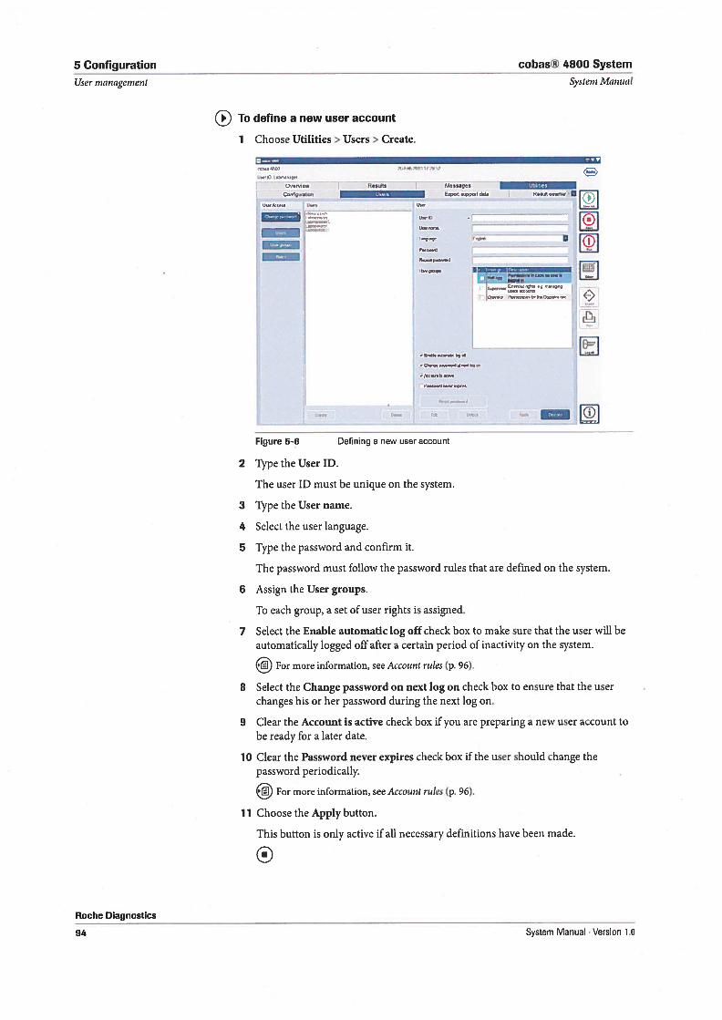
5 Configuration
User management
cobas® 4800 System
Systeni Manual
To define a new user account
1 Choose Utilities> Users> Create.
!._._.Figure 5—6 Defining a new user account
2 Type the User ID.
The user ID must be unique on the system.
3 Type the User name.
4 Select the user language.
5 Type the password and confirm it.
The password must follow the password rules that are defined on the system.
6 Assign the User groups.
To each group, a set of user rights is assigned.
7 Select the Enable automaticlog off check box to make sure that the user will beautomatically logged off after a certain period of inactivity on the system.
For more information, see Account rules (p. 96).
8 Select the Change password on next log on check box to ensure that the userchanges his or her password during the next log on.
9 Clear the Account is active check box if you are preparing a new user account tobe ready for a later date.
10 Clear the Password never expires check box if the user should change thepassword periodically.
For more information, see Account rules (p. 96).
11 Choose the Apply button.
This button is only active if all necessary definitions have been made.
Over ew Rcsuhs MessagesEpppoddst
Sza —,
t R___.,._
. rirr— ,,,,,..,,M.wop,,a S
r)
Roche Diagnostics
94 System Manual . Version 1.0
cobas® 4800 System 5 Configuration
System Manual User management
Changing user accounts
To change a user account
1 Choose Utilities > Users.
2 Select a user from the list.
3 Choose the Edit button.
4 Make the necessary changes.
5 Choose the Apply button.
0Deleting user accounts
To delete a user account
1 Choose Utilities > Users.
2 Select a user from the list.
3 Choose the Delete button.
A confirmation dialog box is displayed.
4 Choose the Yes button to confirm the action.
0
Unlocking user accounts
By default, user accounts become locked after five unsuccessful logon attempts.Locked users are indicated in the Users list.
To unlock a locked user account
1 Choose Utilities > Users.
2 Select the locked user from the list.
3 Choose the Unlock button.
0
Rules
- Utilities > Users > Rules.
There are two sets of rules, one for user accounts and one for passwords.
Enter zero to switch 0ff a rule.
Roche Diagnostics
System Manual Version 1.0 95
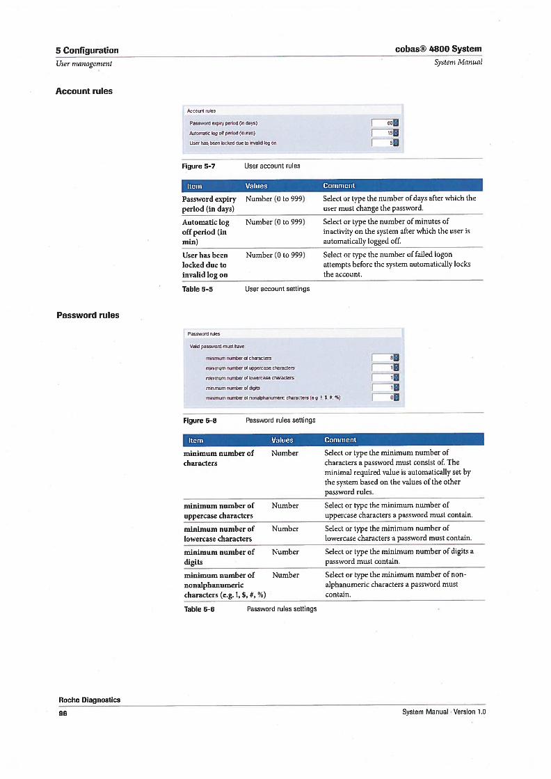
5 Configuration cobas® 4800 System
Accoont rules
Passnord eepny peciod (n days)
Attornahc Ing elf petiod (Nl rtin)
User bas bef n tocked die to nwahd Icg en
Figure 5-7 User account mies
1 so9
r—T 5
Item Values Comment
Automatic Log Number (0 to 999) Select or type the number of minutes ofoffperiod (in inactivity on the system after which the user ismin) automatically logged off.
User has been Number (0 to 999) Select or type the number of failed logonlocked due to attempts before the system automatically locksinvalid log on the account.
Table 5-5 User account settings
Password rutes
vald password roest have
mirumum roimber of characters
minrmum nunter of appercase characters TrntnfiTtlJll nurober & Inwercase r 1
mh,rn,uçnnundeeofdets rmlrsmum number of nondphanurrrenc characters (eg $5. %)
Figure 5-8 Password ruies settings
Item Values Comment
minimum number of Number Select or type the minimum number ofeharacters characters a password must consist of. The
minimal required value is automatically set bythe system based on the values of the otherpassword rules.
minimum number of Number Select or type the minimum number ofuppercase characters uppercase characters a password must contain.
minimum number of Number Select or type the minimum number oflowercase characters lowercase characters a password must contain.
minimum number of Number Select or type the minimum number of digits adigits password must contain.
minimum number of Number Select or type the minimum number of nonnonaiphanumeric alphanumeric characters a password mustcharacters (e.g. !, $, #, %) contain.
System Manual
Password expiry Number (0 to 999)period (in days)
Select or type the number of days after which theuser must change the password.
User management
Account rules
Password rules
Roche Diagnostics
Table 5—6 Password mies settings
96 System Manuai . Version 1.0
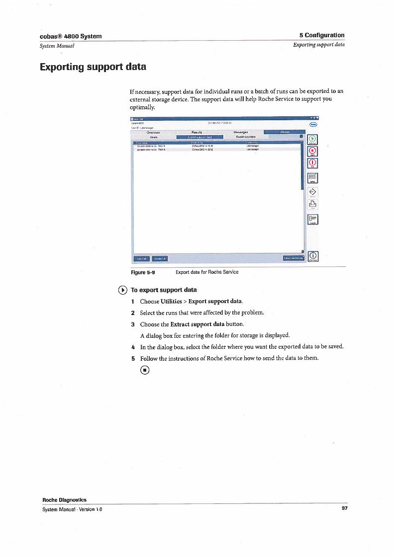
cobas® 4800 System 5 Configuration
Systern Manual Exporting support data
Exporting support data
1f necessary, support data for individual runs or a batch of runs can be exported to an
external storage device. The support data will help Roche Service to support youoptimally.
114 5H—
- overvlew Resuits Mesnges
Veem w.,uIt counters
21-IETS 2012 145 T” A 23.l, 201214 IS St
231104-20,2 1420 0*1,4 02-110.2022142012 L44,emQ,, [E]
Figure 59 Export data for Roche Service
To export support data
1 Choose Utilities> Export support data.
2 Select the runs that were affected by the problem.
3 Choose the Extract support data button.
A dialog box for entering the folder for storage is displayed.
4 In the dialog box, select the folder where you want the exported data to be saved.
5 Follow the instructions of Roche Service how to send the data to them.
0
Roche Diagnostics
System Manual . Version 1.0 97
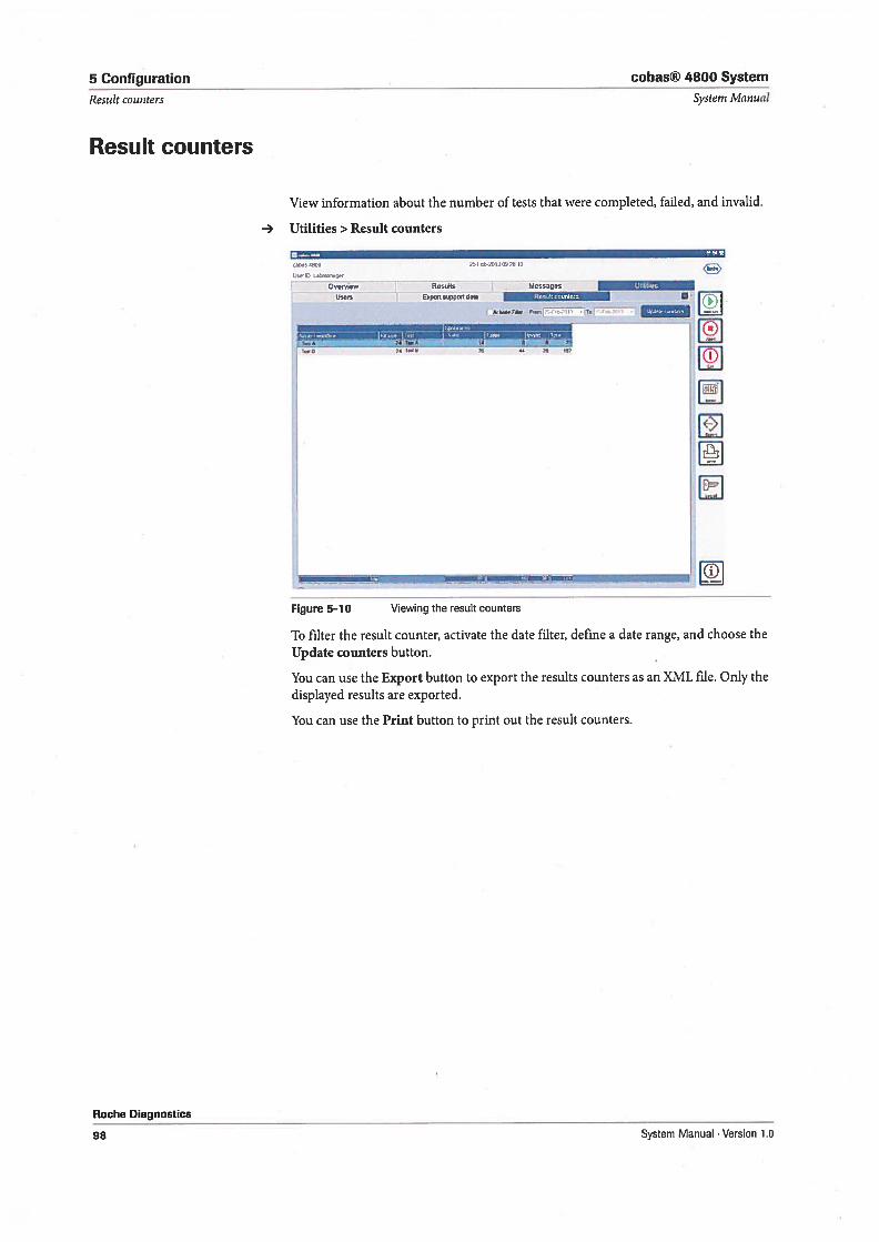
5 Configuration cobas® 4800 System
Result counters System Manual
Result counters
View information about the number of tests that were completed, failed, and invalid.
— Utilities > Result counters
C44a, 4SW Ct-2OI3j2 IU
U44U
Overyw Rs4!ts Messae I5NU,. —
Ur Epo4ppoid4t4 ;ÇWT! kW..F4.# F,,m T., -
441.448 ‘t 44 28 tÇ4
Figure 5—10 Viewing the resultcounters
To filter the result counter, activate the date filter, define a date range, and choose theUpdate counters button.
You can use the Export button to export the resuits counters as an XML file. Only thedisplayed resuits are exported.
You can use the Print button to print out the result counters.
Roche Diagnostics
98 System Manual . Version 1.0
Maintenance
6 Maintenance 101

cohas® 4800 System 6 Maintenance
Toble of contents Systern Monual
Maintenance
In this chapter the required maintenance procedures are described.
In this chapter .
Safety information 103
Instrument maintenance 104
Perform start up procedures 105
General cleaning for the instrument 105
Dailymaintenance 105
Weekly maintenance 110
Analyzer maintenance 115
General cleaning for the analyzer 115
Exchanging the Xenon lamp 116
Exchanging the ventilation dust filters 119
Exchanging fuses 122
Roche Diagnostics
System Manual . Version 1.0 101
6 Maintenance cobas® 4800 System
Table of contents Systern Manual
Roche Diagnostics
102 System Manual . Version 1.0
cobas® 4800 System 6 Maintenance
Systeni Manual Safety information
Safety information
Considerations before operation
Make sure that you have read and understood the chapter General safety information
(p. 13). The following safety messages in particular are relevant:
Warning messages:
• Electrical shock by electronic equipment (p. 18)
• Loss of sight due to staring into laser beam (p. 18)
• Infection and injuîy due to sharp objects (p. 19)
• Infection by samples and associated materials (p. 19)
• Infection by biohazardous waste (p. 19)
• Contamination of the environment by liquid waste and solid waste (p. 19)
• Explosion through sparks (p. 20)
• fire risk through usage of sprays (p. 20)
Caution messages:
• Personal injuîy due to contact with moving parts (p. 20)
• Skin infiammation or injury caused by reagents (p. 21)
• Personal injury due to hot surface (p. 22)
Safety precautions:
• Operator qualification (p. 16)
Observe the system safety labels illustrated and described on Safety labels on the
system (p. 25)
Before performing any maintenance, read the safety messages carefully. 1f you ignoresafety messages, you may suffer serious or fatal injury.
Roche Diagnostics
System Manual Version 1.0 103
6 Maintenance cobas® 4800 System
Instrument maintenance System Manual
Instrument maintenance
Maintenance for the instrument is initiated and managed directly from the software.The System tab shows the actual maintenance status of the instrument. Maintenanceis started from the cobas x 480 tab.
Periodic maintenance must be performed in order to ensure safe and reliableoperation of the instrument. A maintenance procedure is completed once theprocedure has been fully executed and the resuits are within the specifications.
Aborting maintenance procedures A maintenance procedure must always be finalized. Do not abort a maintenanceprocedure. Aborting a maintenance procedure will lead to a failed status, andmaintenance will need to be started again. After aborting a maintenance procedure,switch off the instrument and switch it on again after 10 seconds.
Infection by samples and associated materials
Always wear disposable gloves during maintenance. Pay special attention to the sharp
WARNING edges on the ISWAP and the pipetting channels.
Explosion through sparks
The liquids used for cleaning are flammable.
WARNING Do not clean the instrument in the vicinity of open flames or devices which could
create sparks. Do not use hot air blowers to dry the instrument.
NOTICE Instrument damage and malfunction due to incorrect maintenance
Perform only the maintenance actions described in the daily and weekly maintenance
procedures. No other maintenance is allowed on any module of the instrument.
The following maintenance intervals have to be followed:
Daily maintenance Recommended daily after instrument startup.
Weekly maintenance Recommended at the end of the week before shutting down the instrument.
1f an error is encountered during a maintenance procedure, try to resolve theproblem and re-start the maintenance procedure. 1f you cannot resolve the erroryourself, cail Roche Service.
Preventive inaintenance As part of the preventive service program two scheduled preventive rnaintenanceservice visits per year will be required. Preventive maintenance is performed byRoche Service. The duration of each preventative maintenance procedure will beapproximately 4 hours.
NOTICE Instrument damage and malfunction due to incorrect maintenance
Performing daily and weekly maintenance is mandatory. A run can only be started when
maintenance is complete.
1f any parts of the instrument or carriers have become contaminated, the weekly
maintenance procedure must be performed.
Do not shut down the control unit or the software during a running mainteriance
procedure.
Roche Diagnostics
104 System Manual . Version 1.0
cobas® 4800 System 6 Maintenance
Systeni Ivlanual Instrument maintenance
• Counters are reset to twenty-four hours when daily maintenance is performed. 1fweekly maintenance is performed, daily maintenance is not required on that day.
There is no processing icon like an hourglass or progress bar displayed duringmaintenance.
Perform start up procedures
The system control unit is normally left on, except for a daily restart (e.g. as part orbefore starting the daily maintenance).
It is strongly recommended to restart the system daily.
For startup procedures, if the control unit is powered off, refer to the test-specificOperator’s Manual.
General cleaning for the instrument
Safety
Make sure that you have read and understood the chapter General safety information(p. 13) and Safety information (p. 103)
The surface of the instrument should be cleaned on a weekly basis with a lint-freecloth moistened with deionized water. 1f a spul of reagents occurs, the instrumentshould be cleaned with a 70% ethanol solution.
Removable internal parts of the instrument, such as all carriers, should be weeklyrinsed with deionized water followed by 70% ethanol.The area around the instrumentshould be periodically checked to ensure that air flow around the instrument isunrestricted and that books, papers, or other supplies do not interfere with air flow.Ifa specimen or other biohazardous material spills on the instrument or any of theinstrument carriers, the area or carriers should be cleaned with a decontaminatingand nucleic acid destroying agent, followed by deionized water.
• Do not use other organic solvents (eg., petroleum, benzene, or other solvents) becausethey can damage plastic materials.
• Do not use an alcohol solution with a concentration greater than 70°/s because thismay damage transparent viewing windows.
• Only use completely dry carriers on the instrument.
Daily maintenance
The following tasks are part of the daily maintenance:
1. Shutdown and restart the system control unit.
2. Check 1f instrument deck is clean.
3. Empty the tip waste and the liquid waste container and clean the tip eject plate.
4. The instrument automatically checks the tightness of the pipetting channels.
5. The instrument automatically verifies the functioning of the liquid level detection.
Roche Diagnostics
System Manual Version 1.0 105
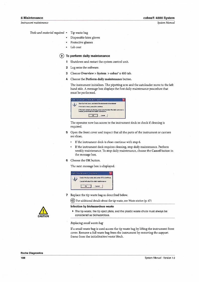
6 Maintenance cobas® 4800 System
Instrument maintenance System Manual
Tools and material required • Tip waste bag
• Disposable latex gloves
• Protective glasses
• Lab coat
To perform daily maintenance
1 Shutdown and restart the system control unit.
2 Log onto the software.
3 Choose Overview> System > cobas° x 480 tab.
4 Choose the Perform daily maintenance button.
The instrument initializes. The pipetting arm and the autoloader move to the lefthand side. A message box displays the first daily maintenance procedure thatmust be performed.
DaiIymatnIenore cIekdeckcteanog
Opoo tbofr toow 5 5kf th kned tob &and,
It de d,kode c4ts ootoe.
II U d ndoto be ded toeooCeeI Wttbedavmtenooe.Ineteed, peeonedMhdne o.eebty n,Ônnoe.
ILZ...i:z_:.JI 1
The operator now has access to the instrument deck to check if cleaning isrequired.
5 Open the front cover and inspect that all the parts of the instrument or carriersare clean.
• 1f the instrument deck is clean continue with step 6.
• 1f the instrument deck requires cleaning, stop daily maintenance. Performweekly maintenance. To stop daily maintenance, choose the Cancel button inthe message box.
6 Choose the 0K button.
The next message box is displayed.
Oaily rndiIItendnce tip wdste
the 14e wasoe ond peeso O+ to cordnoe.
Cel oel aboet the day raatetenanoe
j Cancel
7 Replace the tip waste bag as described below.
For additional details about the tip waste, see I’Vaste station (p. 47)
Infection by biohazardous waste
The tip waste, the tip eject plate, and the plastic waste chute must always be
CAUTION considered as biohazardous.
Replacing small waste bag
1f a small ivaste bag is used access the tip waste bag by lifting the instrument frontcover. Remove a full waste bag from the instrument by removing the supportframe from the initialization/waste block.
Roche Diagnostics
106 System Manual . Version 1.0
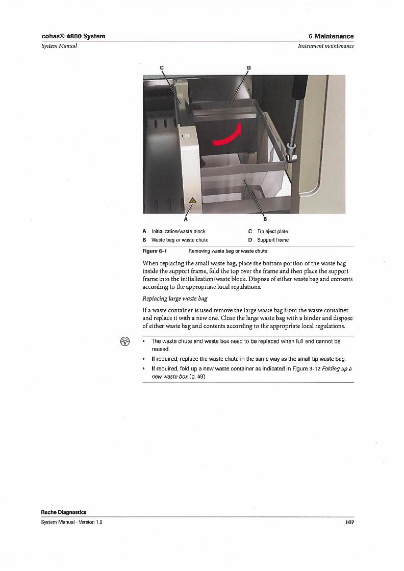
cobas® 4800 System 6 Maintenance
Systern Manual Instrument maintenance
Roche Diagnostics
A Initialization/waste block
B Waste bag or waste chute
Figure 6-1 Removing waste bag or waste chute
7When replacing the small waste bag, place the bottom portion of the waste baginside the support frame, fold the top over the frame and then place the supportframe into the initialization/waste block. Dispose of either waste bag and contentsaccording to the appropriate local regulations.
Replacing large waste bag
1f a waste container is used remove the large waste bag from the waste containerand replace it with a new one. Close the large waste bag with a binder and disposeof either waste bag and contents according to the appropriate local regulations.
• The waste chute and waste box need to be replaced when full and cannot bereused.
• 1f required, replace the waste chute in the same way as the small tip waste bag.
• 1f required, fold up a new waste container as indicated in Figure 3-12 Folding up anew waste box (p. 49)
C Tip eject plate
D Support frame
System Manual . Version 1.0 107
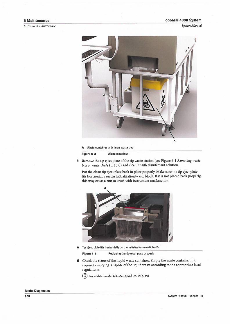
6 Maintenance cohas® 4800 System
Instrttnient nzaintenance Systern Manual
Roche Diagnostics
A Waste container with large waste hag
Figure 6-2
8 Remove the tip eject plate of the tip waste station (see Figure 6-1 Reinovingwaste
bag or waste chute (p. 107)) and clean it with disinfectant solution.
Put the clean tip eject plate back in place properly. Make sure the tip eject platefits horizontally on the initialization/waste block. 1f it is not placed back properly,this may cause a run to crash with instrument malfunction.
A
A Tip eject plate fits horizontally on the initialization/waste block
Figure 6-3 Replacing the tip eject plate properly
9 Check the status of the liquid waste container. Empty the waste container ifitrequires emptying. Dispose of the liquid waste according to the appropriate localregulations.
For additional details, see Liquid waste (p. 49)
Waste container
108 System Manual Version 10
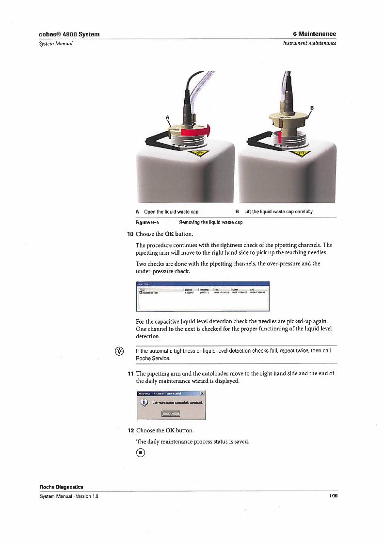
cobas® 4800 System 6 Maintenance
Systeni Manuni
A Open the liquid waste cap.
Figure 6-4
Instrument maintenance
10 Choose the 0K button.
The procedure continues with the tightness check of the pipetting channels. Thepipetting arm will move to the right hand side to pick up the teaching needies.
Two checks are done with the pipetting channels, the over-pressure and theunder-pressure check.
flt TWI3 ITIB29 I7I&Z %171&ï4
Roche Diagnostics
For the capacitive liquid level detection check the needies are picked-up again.One channel to the next is checked for the proper functioning of the liquid leveldetection.
1f the automatic tightness or liquid level detection checks fail, repeat twice, then calI
Roche Service.
11 The pipetting arm and the autoloader move to the right hand side and the end ofthe daily maintenance wizard is displayed.
4) by
L-z:zz]I
12 Choose the 0K button.
The daily maintenance process status is saved.
0
B Lift the liquid waste cap carefully
Removing the liquid waste cap
System Manual Version 1.0 109
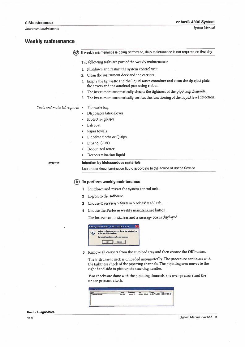
6 Maintenance cobas® 4800 System
1nstrumeHt ninintenance Systern Manual
Weekly maintenance
1f weekly maintenance is being performed, daily maintenance is not required on that day.
The following tasks are part of the weekly maintenance:
1. Shutdown and restart the system control unit.
2. Clean the instrument deck and the carriers.
3. Empty the tip waste and the liquid waste container and clean the tip eject plate,
the covers and the autoload protecting ribbon.
4. The instrument automatically checks the tightness of the pipetting channels.
5. The instrument automatically verifies the functioning of the liquid level detection.
Tools and inaterial required • Tip waste bag
• Disposable latex gloves
• Protective glasses
• Lab coat
• Paper towels
• Lint-free cloths or Q-tips
• Ethanol (70%)
• De-ionized water
• Decontamination liquid
NOTICE Infection by biohazardous materials
Use proper decontamination liquid according to the advice of Roche Service.
To perform weekly maintenance
1 Shutdown and restart the system control unit.
2 Log on to the software.
3 Choose Overview> System> cobas x 480 tab.
4 Choose the Perform weekly maintenance button.
The instrument initializes and a message box is displayed.
Weeky maItennte ctrnek uto(od tray-
Md. the,,,,, ,he , the
Cre ed b,.t the .e,,
Icz.:zz4
5 Remove all carriers from the autoload tray and then choose the 0K button.
The instrument deck is unloaded automatically. The procedure continues with
the tightness check of the pipetting channels. The pipetting arm moves to the
right hand side to pick up the teaching needles.
Two checks are done with the pipetting channels, the over-pressure and the
under-pressure check.
r_
Roche Diagnostics
110 System Manual . Version 1.0
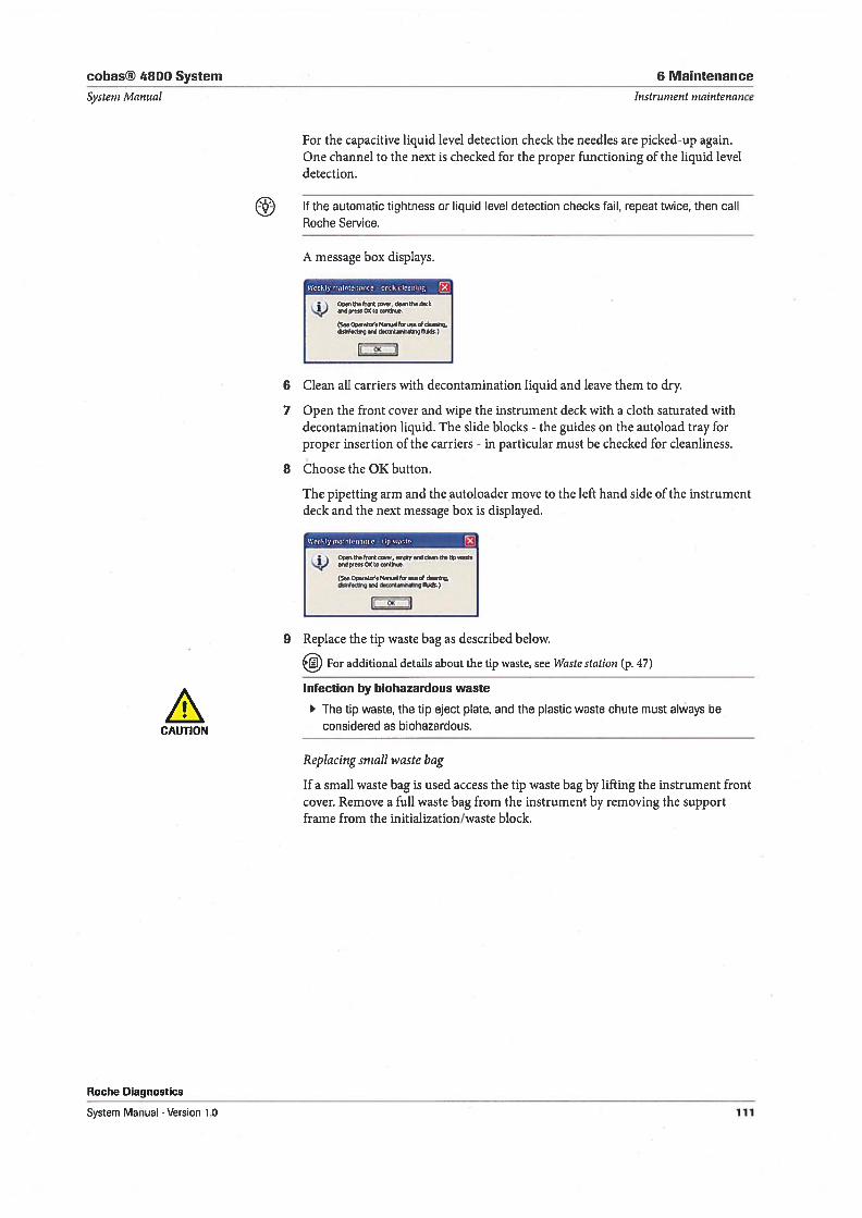
cobas® 4800 System 6 Maintenance
Systenz Mannal Instrument maintenance
For the capacitive liquid level detection check the needies are picked-up again.One channel to the next is checked for the proper functioning of the liquid leveldetection.
1f the automatic tightness or liquid level detection checks fail, repeat twice, then caliRoche Service.
A message box displays.
Wcofdymofntenance - deckcloartlng
• Opeftfooo&ontherkok
(SooOpooot Monodto o of deoorto*otg d doo*&çfhdo,)
6 Clean all carriers with decontamination liquid and leave them to dry.
7 Open the front cover and wipe the instrument deck with a cloth saturated withdecontamination liquid. The slide blocks - the guides on the autoload tray forproper insertion of the carriers - in particular must be checked for cleanliness.
8 Choose the 0K button.
The pipetting arm and the autoloader move to the left hand side of the instrumentdeck and the next message box is displayed.
WeekLymafntennc . Upwaste
C’pso tto Frt oovo, on,ptyo,,ddoovthe t woot4) on poovs co to
(Sos Opooto,s Mov,off .o of oI’o’ns.ooisot Ond dsoordovdndingtlof.)
l[z2Z4
9 Replace the tip waste bag as described below.
For additional details about the tip waste, see Waste station (p. 47)
Infection by biohazardous waste
The tip waste, the tip eject plate, and the plastic waste chute must always be
CAUTION considered as biohazardous.
Replacing small waste bag
1f a small waste bag is used access the tip waste bag by lifting the instrument frontcover. Remove a full waste bag from the instrument by removing the supportframe from the initialization/waste block.
Roche Diagnostics
System Manual . Version 1.0 111

6 Maintenance cobas® 4800 System
Instrument mainlenance Systeni Manual
Removing waste bag or waste chute
When replacing the small waste bag, place the bottom portion of the waste baginside the support frame, fold the top over the frame and then place the supportframe into the initialization/waste block. Dispose of either vaste bag and contentsaccording to the appropriate local regulations.
Replacing large waste bag
1f a waste container is used remove the large ivaste bag from the waste containerand replace it with a new one. Close the large waste bag with a binder and disposeof either waste bag and contents according to the appropriate local regulations.
• Waste chute and waste container can be reused and need to be replaced only ifrequired.
• 1f required, replace the waste chute in the same way as the small tip waste bag.
• 1f required, fold up a new waste container as indicated in Figure 3-12 Fo/ding up anew waste box (p. 49)
C D
A Initialization/waste block C Tip eject plate
B Waste bag or waste chute D Support frame
Figure 6-5
Roche Diagnostics
112 System Manual . Version 1.0
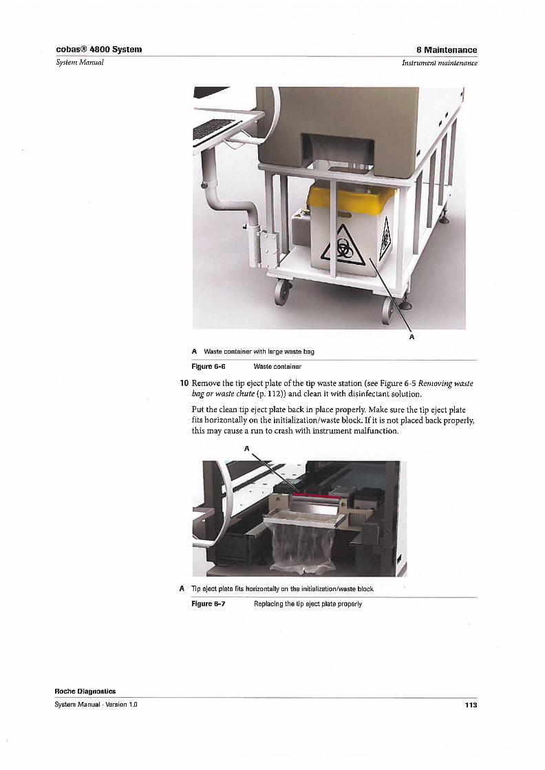
cobas® 4800 System
Systern Manual
Roche Diagnostics
System Manual . Version 1.0
6 Maintenance
Instrument niaintenance
A Waste container with large waste bag
Figure 6-6 Waste container
10 Remove the tip eject plate of the tip waste station (see Figure 6-5 Removing wastebag or waste chute (p. 112)) and clean 11 with disinfectant solution.
Put the clean tip eject plate back in place properly. Make sure the tip eject platefits horizontally on the initialization/waste block. 1f it is not placed back properly,this may cause a run to crash with instrument malfunction.
A Tip eject plate fits horizontally on the initialization/waste block
Figure 6—7 Replacing the tip eject plate properly
113
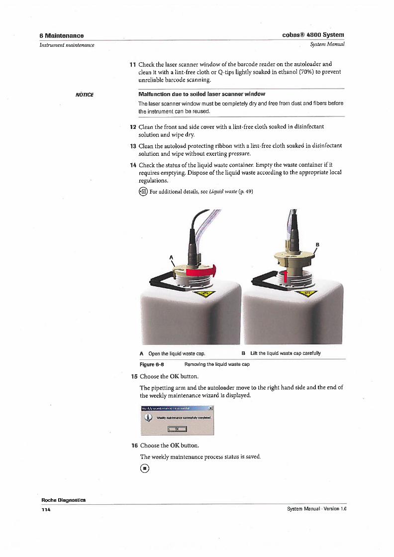
6 Maintenance cobas® 4800 System
Instrument maintenance Systern Manual
NÖTJCE
Roche Diagnostics
11 Check the laser scanner window of the barcode reader on the autoloader andclean it with a lint-free cloth or Q-tips lightly soaked in ethanol (70%) to preventunreliable barcode scanning.
Malfunction due to soiled laser scanner window
The laser scanner window must be complet&y dry and free from dust and fibers before
the instrument can be reused.
12 Clean the front and side cover with a lint-free cloth soaked in disinfectantsolution and wipe dry.
13 Clean the autoload protecting ribbon with a lint-free cloth soaked in disinfectantsolution and wipe without exerting pressure.
14 Check the status of the liquid waste container. Empty the waste container if it
requires emptying. Dispose of the liquid vaste according to the appropriate localregulations.
For additional details, see Liquid waste (p. 49)
A Open the liquid waste cap.
Figure 6-8
15 Choose the 0K button.
The pipetting arm and the autoloader move to the right hand side and the end ofthe weekly maintenance wizard is displayed.
WeeI,ly ,nintenfle -
Wdy n,*ne efdy o.etd
rzJJ
16 Choose the 0K button.
The weekly maintenance process status is saved.
B Lift the liquid waste cap carefully
Removing the liquid waste cap
114 System Manual Version 1.0
cobas® 4800 System 6 Maintenance
Systeni Manual Analyzer maintenance
Analyzer maintenance
No user maintenance is required for the analyzer. General cleaning of the analyzerand exchanging the Xenon lamp, the ventilation dust filters, and the fuses aredescribed below.
Electrical shock by electronic equipment
Never clean the analyzer without turning the analyzer power switch off and
WARNING disconnecting the power cable.
Do not pour fluids into the interior of the analyzer or onto any parts of the analyzer.
Infection by samples and associated materials
As with all potentially biohazardous specimens, universal safety precautions should be
WARNING taken when handling and processing samples. Spills should be immediately disinfected
with an appropriate disinfectant solution to avoid spreading contamination to
laboratory personnel or equipment. Handling and disposal of infectious material should
be performed according to local safety guidelines.
General clean ing for the analyzer
Regular cleaning of the analyzer and the accessories is not required. 1f necessary,clean the housing of the analyzer, the thermal block cycler, and the block cycler coverwith 70% ethanol.
Erroneous resuits due to dirty ventilation inlets
1f the ventilation inlets are not replaced regularly, the lense could get dirfy, and this could
WARNING cause an erroneous result.
Ensure that the ventilation dust filters are replaced twice a year.
Ventilation inlets The ventilation inlets of the analyzer should be checked regularly, to ensure anunrestricted air flow. You should ensure that the ventilation dust filters are replaced
twice a year.
For details, see Exchanging the ventilation dust filters (p. 119).
Roche Diagnostics
System Manual . Version 1.0 115
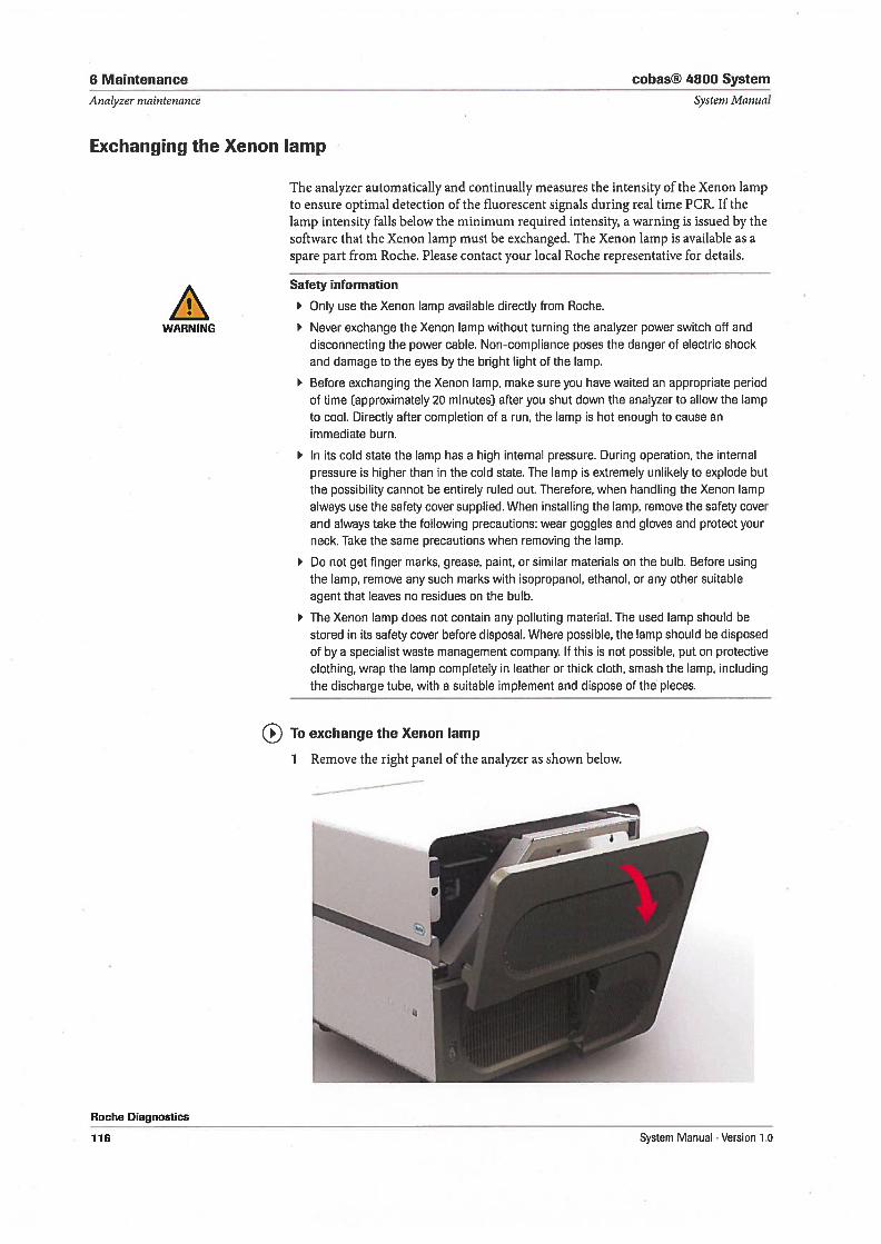
6 Maintenance cobas® 4800 System
Analyzer nsaintenance Systern Ivlanual
Exchanging the Xenon lamp
The analyzer automatically and continually measures the intensity of the Xenon lampto ensure optimal detection of the fluorescent signals during real time PCR. 1f thelamp intensity falis below the minimum required intensity, a warning is issued by thesoftware that the Xenon lamp must be exchanged. The Xenon lamp is available as aspare part from Roche. Please contact your local Roche representative for details.
Safety information
Only use the Xenon lamp available directly from Roche.
WARNING Never exchange the Xenon lamp without turning the analyzer power switch off anddisconnecting the power cable. Non-compliance poses the danger of electric shockand damage to the eyes by the bright light of the lamp.
Before exchanging the Xenon lamp, make sure you have waited an appropriate periodof time (approximately 20 minutes) after you shut down the analyzer to allow the lampto cool. Directly after completion of a run, the lamp is hot enough to cause animmediate burn.
In its cold state the lamp has a high internal pressure. During operation, the internalpressure is higher than in the cold state. The lamp is extremely unlikely to explode butthe possibility cannot be entirely ruled out. Therefore, when handling the Xenon lampalways use the safety cover supplied. When installing the lamp, remove the safety coverand always take the following precautions: wear goggles and gloves and protect yourneck. Take the same precautions when removing the lamp.
Do not get finger marks, grease, paint, or similar materials on the bulb. Before usingthe lamp, remove any such marks with isopropanol, ethanol, or any other suitableagent that leaves no residues on the bulb.
The Xenon lamp does not contain any polluting material. The used lamp should bestored in its safety cover before disposal. Where possible, the lamp should be disposedof by a specialist waste management company. 1f this is not possible, put on protectiveclothing, wrap the lamp completely in leather or thick cloth, smash the lamp, includingthe discharge tube, with a suitable implement and dispose of the pieces.
To exchange the Xenon lamp
Roche Diagnostics
116
1 Remove the right panel of the analyzer as shown below.
System Manual . Version 1.0
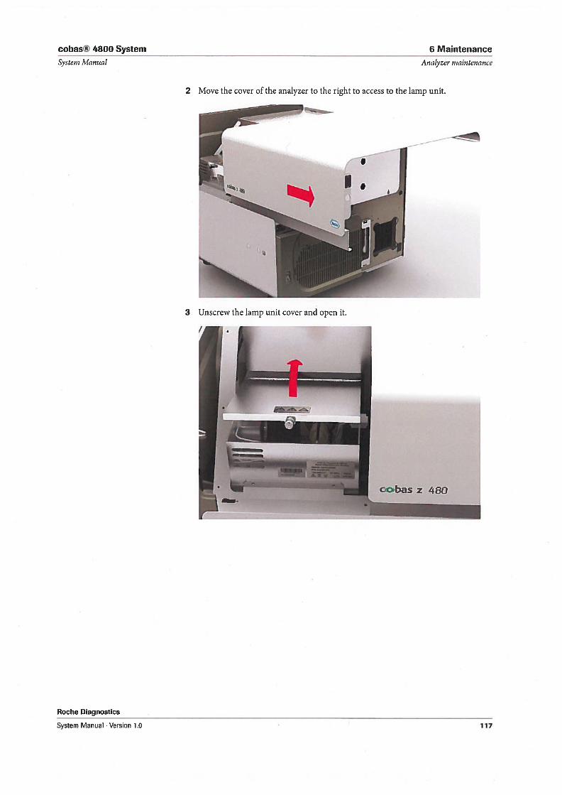
cobas® 4800 System
Systern Manual
6 Maintenance
Analyzer nrnintenance
2 Move the cover of the analyzer to the right to access to the lamp unit.
------.<-
Roche Diagnostics
System Manual . Version 1.0
4. 1
3 Unscrew the lamp unit cover and open it.
1 cobas z 480
117
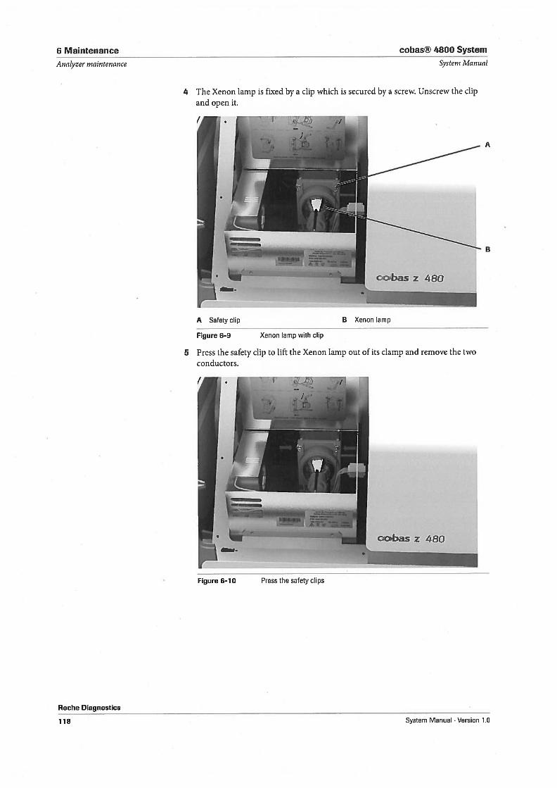
6 Maintenance
Analyzer maintenance
cobas® 4800 System
Systeni ManHal
4 The Xenon lamp is fixed by a clip which is secured by a screw. Unscrew the clipand open it.
.1
Roche Diagnostics
-/Ik.
,0% -
cbas z 480
A Safety clip B Xenon lamp
Figure 6-9 Xenon lamp with clip
5 Press the safety clip to lift the Xenon lamp out of its clamp and remove the twoconductors.
cobas z 480
Figure 6—10 Press the safety clips
118 System Manual . Version 1.0
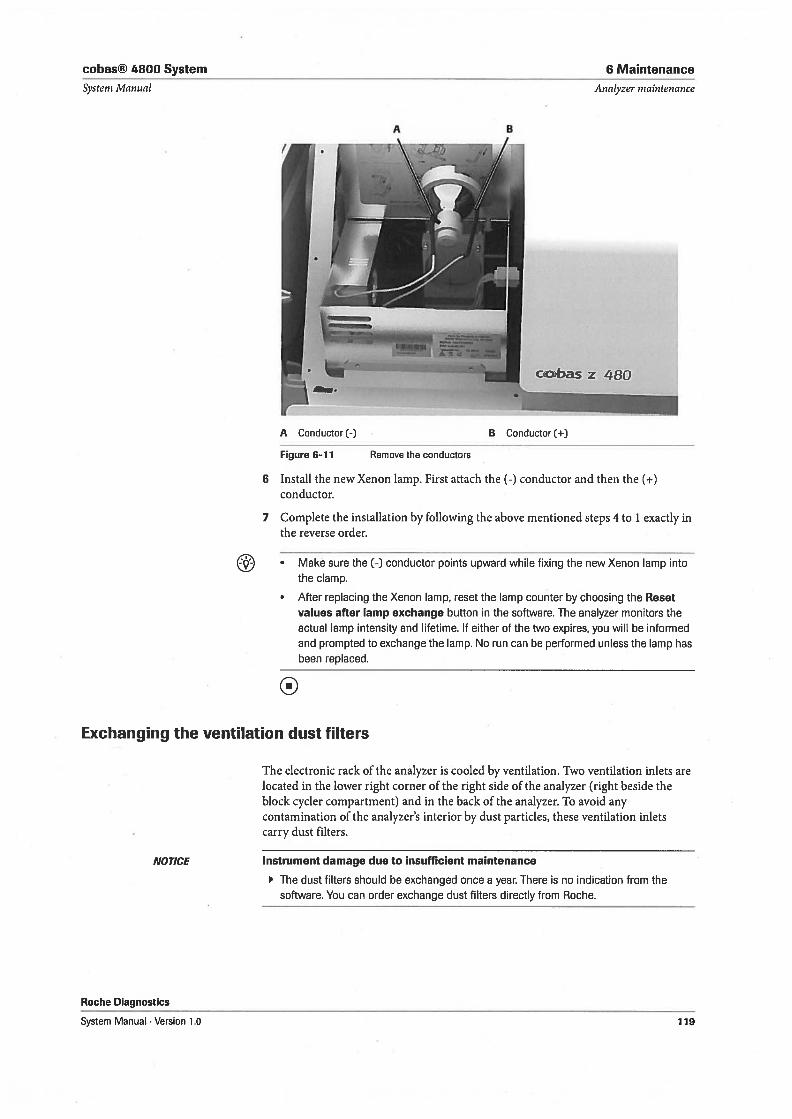
cobas® 4800 System 6 Maintenance
Systeni Manual
A Conductor(-)
Analyzer nzaintenance
1B Conductor (+)
Figure 6-11 Remove the conductors
6 Instail the new Xenon lamp. First attach the (-) conductor and then the (+)conductor.
7 Complete the installation by following the above mentioned steps 4 to 1 exactly inthe reverse order.
• Make sure the (-) conductor points upward while fixing the new Xenon lamp intothe clamp.
• After replacing the Xenon lamp, reset the lamp counter by choosing the Reset
values after lamp exchange button in the software. The analyzer monitors theactual lamp intensity and lifetime. 1f either of the two expires, you will be informedand prompted to exchange the lamp. No run can be performed unless the lamp hasbeen replaced.
0
Exchanging the ventilation dust filters
NOTICE
Roche Diagnostics
The electronic rack of the analyzer is cooled by ventilation. Two ventilation inlets arelocated in the lower right corner of the right side of the analyzer (right beside theblock cycler compartment) and in the back of the analyzer. To avoid anycontamination of the analyzer’s interior by dust particles, these ventilation inletscarry dust filters.
Instrument damage due to insufficient maintenance
The dust filters should be exchanged once a year. There is no indication from thesoftware. You can order exchange dust filters directly from Roche.
-.\‘
:!!“ L._oosbas z 480
System Manual . Version 1.0 119
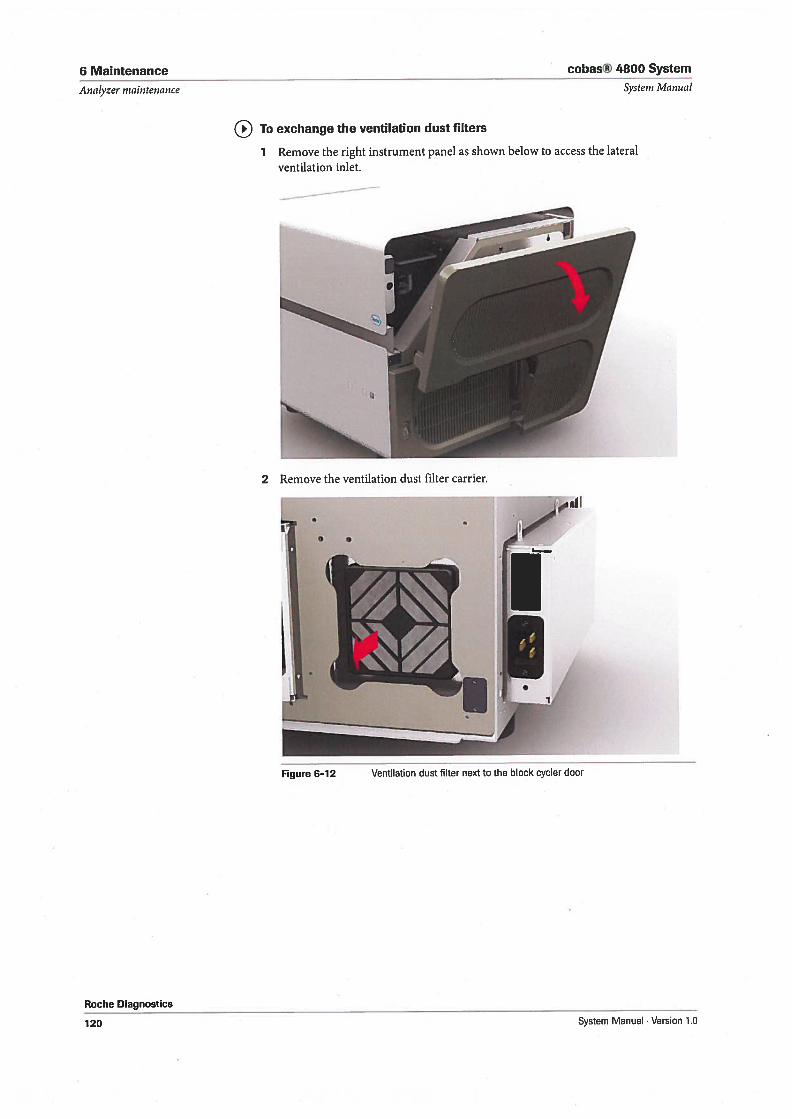
6 Maintenance
Analyzer maintenance
cohas® 4800 System
Systern Manuat
To exchange the ventilation dust filters
1 Remove the right instrument panel as shown below to access the lateralventilation inlet.
Roche Diagnostics
2 Remove the ventilation dust filter carrier.
120 System Manual . Version 1.0
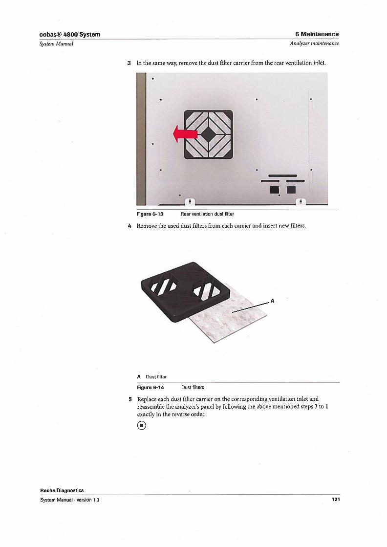
cobas® 4800 System 6 Maintenance
Systern Manual Analyzer maintenance
3 In the same way, remove the dust filter carrier from the rear ventilation inlet.
Roche Diagnostics
Figure 6—13 Rearventilation dust filter
4 Remove the used dust filters from each carrier and insert new filters.
A Dust filter
Figure 6-14 Dust filters
5 Replace each dust filter carrier on the corresponding ventilation inlet andreassemble the analyzer’s panel by following the above mentioned steps 3 to 1
exactly in the reverse order.
0
System Manual Version 1.0 121
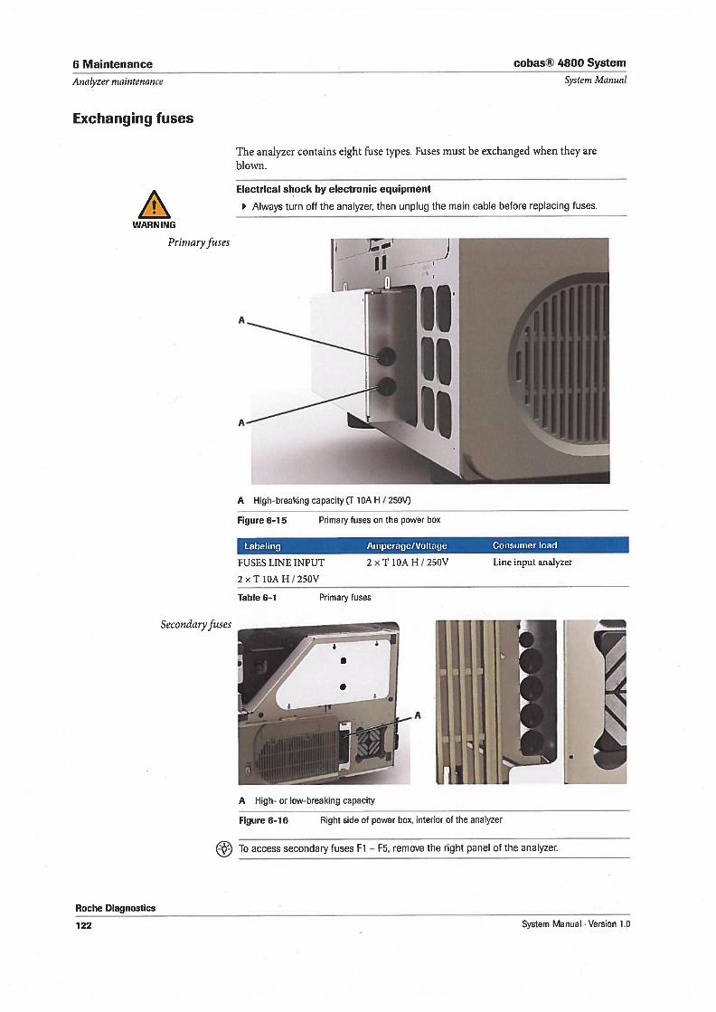
6 Maintenance
Analyzer maintenance
Exchanging fuses
cobas® 4800 System
System Manual
The analyzer contains eight fuse types. Fuses must be exchanged when they areblown.
A High-breaking capacity (T 1OA H / 250V)
Figure 6-15 Primary fuses on the power box
Labeling Amperage/Voltage Consumer bad
FUSES LINE INPUT 2 x T 1OA H / 250V Line input analyzer
2 x T 1OA H / 250V
Table 6-1 Primary fuses
To access secondary fuses El — F5, remove the right panel of the analyzec
Roche Diagnostics
Electrical shock by electronic equipment
Always turn off the analyzer, then unplug the main cable before replacing fuses.
WARNING
Prirnaryfuses
Secondaryfuses
A High- or low-breaking capacity
Figure 6—16 Right side of power box, interior of the analyzer
122 System Manual Version 1.0
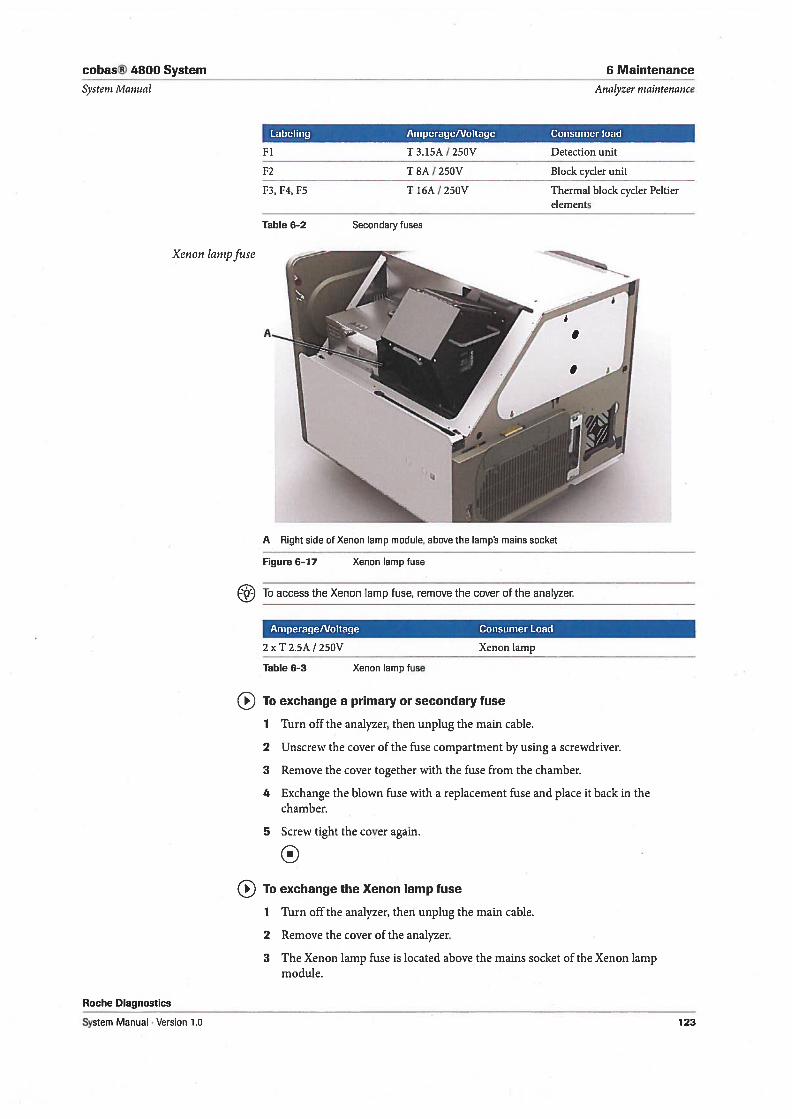
cohas® 4800 System
Systeni Manual
6 Maintenance
Analyzer niaintenance
Labeling Amperage/Voltage Consumer bad
F1 T 3.15A / 250V Detection unit
F2 T 8A / 250V Black cycler unit
F3, F4, F5 T 16A / 250V Thermal block cycler Peltierelements
Table 6-2 Secondary fuses
A Right side of Xenon lamp module, above the lamp’s mains socket
Figure 6-17 Xenon lamp fuse
To access the Xenon lamp fuse, remove the cover of the analyzer.
AmperagelVoltage Consumer bad
2 x T 2.5A / 250V
Table 6-3
Xenon lamp
Roche Diagnostics
System Manual . Version 1.0
To exchange a primary or secondary fuse
1 Turn off the analyzer, then unplug the main cable.
2 Unscrew the cover of the fuse compartment by using a screwdriver.
3 Remove the cover together with the fuse from the chamber.
4 Exchange the blown fuse with a replacement fuse and place it back in thechamber.
5 Screw tight the cover again.
0To exchange the Xenon lamp fuse
1 Turn off the analyzer, then unplug the main cable.
2 Remove the cover of the analyzer.
3 The Xenon lamp fuse is located above the mains socket of the Xenon lampmodule.
Xenon lanipfuse
Xenon lamp fuse
123
6 Maintenance cobas® 4800 System
Analyzer niaintenance Systern Manual
4 Using forceps, press the clamps of the left and right side of the fuse holder inward.PuIl the fuse holder out of its chamber.
5 Exchange the blown fuse with a replacement fuse and place the fuse holder backin the chamber.
6 Re-attach the instrument cover.
Roche Diagnostics
124 System Manual . Version 1.0
Troubleshooting
7 Troubleshooting 127

cobas® 4800 System 7 Troubleshooting
Table of contents Systeni Manual
Troubleshooting
In this chapter alarm and troubleshooting information help to deal with exceptional
situations.
In this chapter Chapter.N
Overview 129
Messages work area 131
Reviewing and confirming new alarms 132
About result flags 134
General troubleshooting 136
Problem reports 136
Remote support 136
LIS troubleshooting 137
Hardware troubleshooting 138
Instrument 138
Barcode reading errors 138
Instrument connection problems 139
Run recovery 140
Remote support 140
Unloading the instrument deck manually 140
Take out of operation 141
Analyzer 141
Analyzer connection problems 141
Analyzer not working 141
Red status LEDs 142
142
Roche Diagnostics
System Manual . Version 1.0 . 127
7 Troubleshooting cobas® 4800 System
Table of contents System Manual
Roche Diagnostics
128 System Manual •Version 1.0
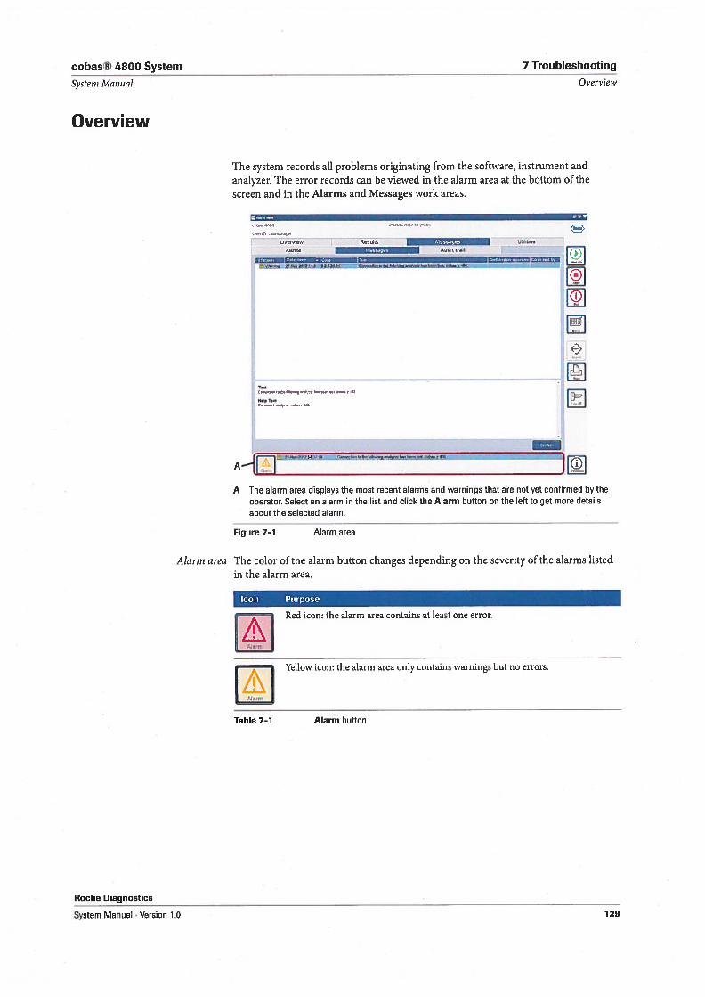
cobas® 4800 System 7 Troubleshooting
System Manual Overview
Overview
The system records all problems originating from the software, instrument andanalyzer. The error records can be viewed in the alarm area at the bottom of thescreen and in the Alarms and Messages vork areas.
UwU1sbm,M
-
Overyrew Resuits Y.l4ttri-p UbirtiesAiarms ,,-,—;.r* Audrt Iran
Ø2!4.R, 4MUL: ..
A .
A Iiie alarm area displays the most recent alarms and warnings that are not yet confirmed by the
operator. Select an alarm in the list and dick the Alarm button on the left to get more details
about the selected alarm.
Figure 7-1 Alarm area
Alarm area The color of the alarm button changes depending on the severity of the alarms listedin the alarm area.
loon Purpose
1Red icon: the alarm area contains at least one error.
Yellow icon: the alarm area only contains warnings but no errors.
Table 7-1 Alarm button
Roche Diagnostios
System Manual . Version 1.0 129
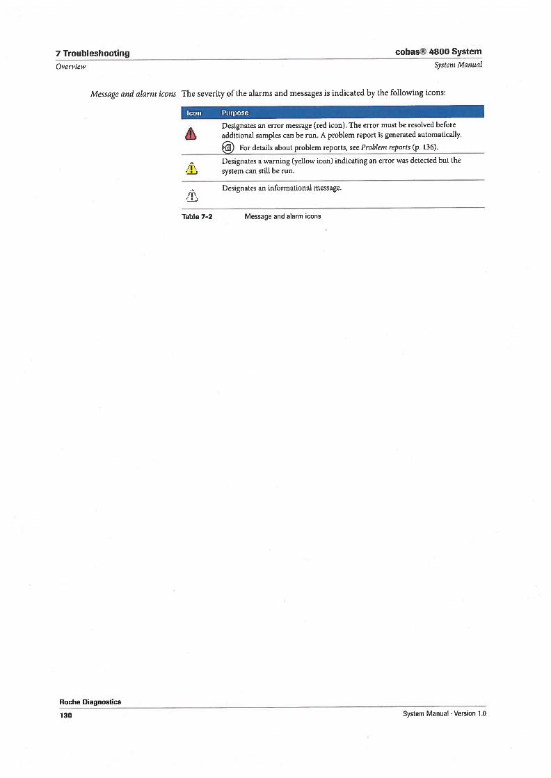
7 Troubleshooting cobas® 4800 System
Oi’ervieiv Systeni Mawal
Message and alarm icons The severity of the alarms and messages is indicated by the following icons:
Icon Purpose
Designates an error message (red icon). The error must be resolved beforeadditional samples can be run. A problem report is generated automatically.
Ï?iiJ For details about problem reports, see Problen, reports (p. 136).
Designates a warning (yellow icon) indicating an error was detected but thesystem cao still be run.
Designates an informational message.
Table 7—2 Message and alarm icons
Roche Diagnostics
130 System Manual . Version 1.0
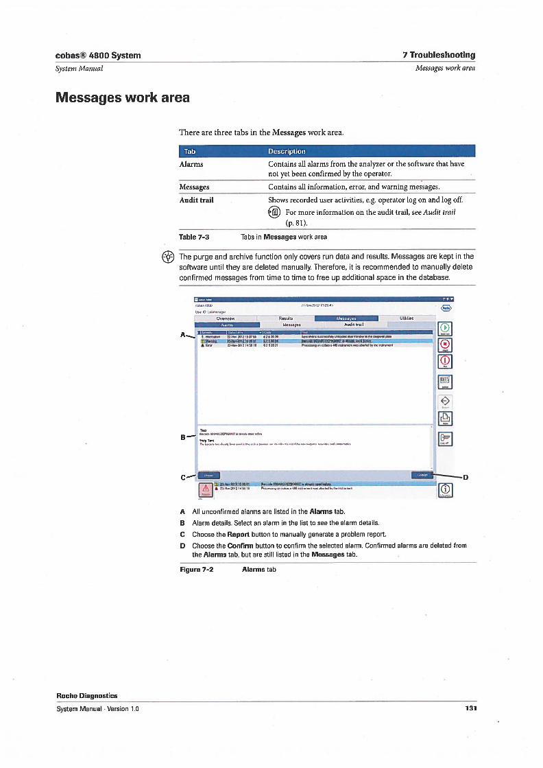
cobas® 4800 System
Systeni Man ual
Messages work area
There are three tabs in the Messages work area.
7 Troubleshooting
Messages ivork area
Tab Description
Alarms Contains all alarms from the analyzer or the software that havenot yet been confirmed by the operator.
Messages Contains all information, error, and warning messages.
Audit trail Shows recorded user activities, e.g. operator log on and log off.
For more information on the audit trail, see Audit (rai!
(p. 81).
Table 7-3 Tabs in Messages work area
The purge and archive function only covers run data and resuits. Messages are kept in the
software until they are deleted manually. Therefore, it is recommended to manually delete
confirmed messages from time to time to free up additional space in the database.
U5o3b04n4n49,0
024,06w
A I’’”S nornioon 24 41002012160153 5262026
*e**rA 4100 23000-2612145514 6252421
Resuits 2,-0vfl.fl
Mossago; Audit tra,I
5p4146404 1100S446S4L42042MFIF40d4644fl4IWW4445244
p4,24,gon,nsa,a4a0Èa.tt.w4624u16446uz8gnn46u
Roche Diagnostics
System Manual . Version 1.0
B —
D
E:IA All unconfirmed alarms are listed in the Alarms tab.
B Alarm details. Select an alarm in the list to see the alarm details.
C Choose the Report button to manually generate a problem report.
D Choose the Confirm button to confirm the selected alarm. Confirmed alarms are deleted fromthe Alarms tab, but are still listed in the Messages tab.
Figure 7-2 Alarms tab
131
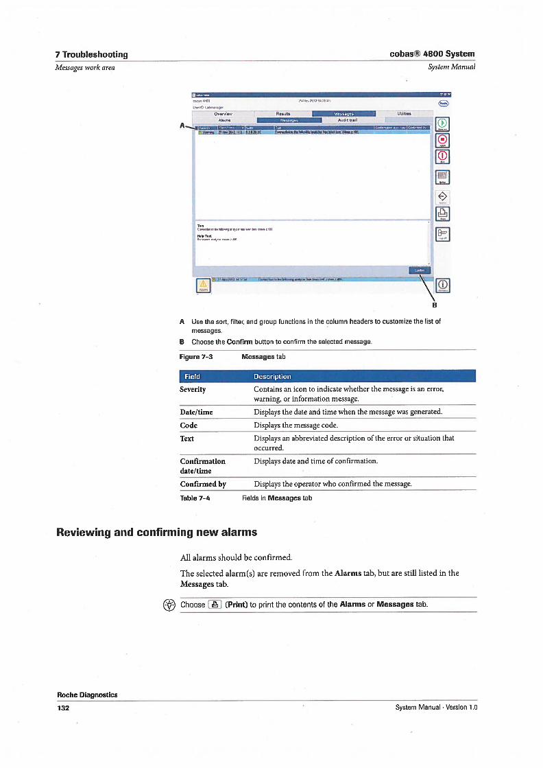
7 Troubleshooting
Ivlessages ivork area
cobas® 4800 System
System Iianual
U5eD J),:
Overv:ew ResisAdit til
T.
A Use the sort, filter, and group functions in the column headers to customize the list ofmessages.
B Choose the Confirm button to confirm the selected message.
Figure 7-3 Messages tab
Field Description
Severity Contains an icon to indicate whether the message is an error,warning, or information message.
Date/time Displays the date and time when the message was generated.
Code Displays the message code.
Text Displays an abbreviated description of the error or situation thatoccurred.
Confirmation Displays date and time of confirmation.date/time
Confirmed by Displays the operator who confirmed the message.
Table 7-4 Fields in Messages tab
All alarms should be confirmed.
The selected alarm(s) are removed from the Alarms tab, but are stil listed in theMessages tab.
Choose . (Print) to print the contents of the Alarms or Messages tab.
Reviewing and confirming new alarms
Roche Diagnostics
132 System Manual . Version 1.0
cobas® 4800 System 7 Troublesliooting
Systern Manual Messages work area
To confirm a new alarm
1 Choose Messages > Alarms or double-dick the alarm in the alarm area at the
bottom of the screen.
2 Select the alarm to be confirmed.
• To select several nonadjacent alarms, use the Ctrl key.
• To select a range of adjacent alarms, use the Shift key.
3 Choose the Confirm button.
0
Roche Diagnostics
System Manual . Version 1.0 133
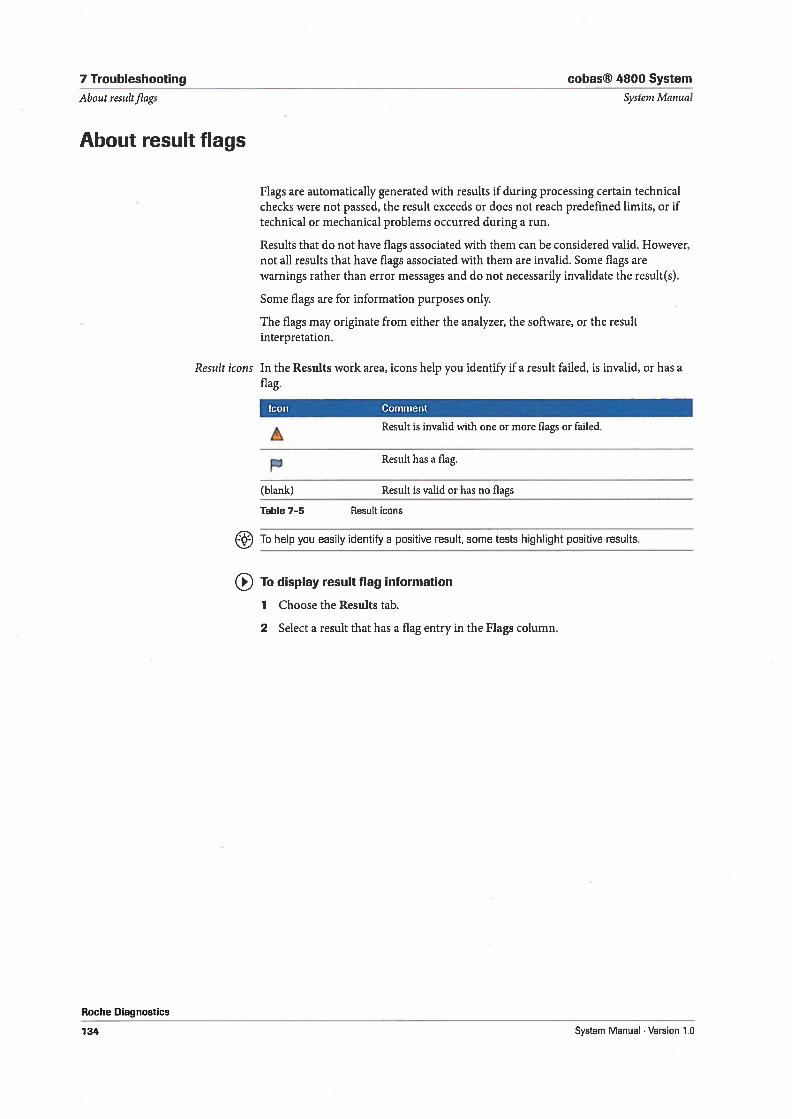
7 Troubleshooting cobas® 4800 System
About resuitfiags Systeni Manual
About result flags
Flags are automatically generated with resuits ifduring processing certain technicalchecks were not passed, the result exceeds or does not reach predefined limits, or iftechnical or mechanical problems occurred during a run.
Results that do not have flags associated with them can be considered valid. However,not all results that have flags associated with them are invalid. Some flags arewarnings rather than error messages and do not necessarily invalidate the result(s).
Some flags are for information purposes only.
The flags may originate from either the analyzer, the software, or the resultinterpretation.
Result icons In the Resuits work area, icons help you identify if a result failed, is invalid, or has aflag.
Icon Comment
Result is invalid with one or more flags or failed.
Result has a flag.
(blank) Result is valid or has no flags
Table 7-5 Result icons
To help you easily identify a positive result, some tests highlight positive results.
To display result flag information
1 Choose the Resuits tab.
2 Select a result that has a flag entry in the Flags column.
Roche Diagnostics
134 System Manual . Version 1.0
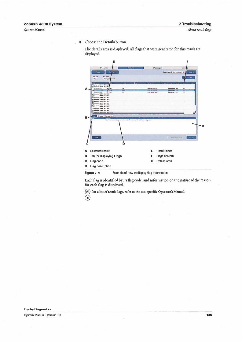
cobas® 4800 System 7 Troubleshooting
Systern Manual About resuitfiags
3 Choose the Details button.
The details area is displayed. All flags that were generated for this result aredisplayed.
E F
/ Mesogs uti:t.j
____
_s_
___________
1 r-fr
A
_______________________________________________________________________
IIU .
B-’
/ \
_
/ \C D
A Selected result E Result icons
B Tab for displaying Flags F Flags column
C Flag code G Details area
D Flag description
Figure 7—4 Example of how to display flag information
Each flag is identified by its flag code, and information on the nature of the reasonfor each flag is displayed.
For a list of result flags, refer to the test-specific Operator’s Manual.
Roche Diagnostics
System Manual . Version 1.0 135
7 Troubleshooting cobas® 4800 System
General troubleshooting Systern Manual
General troubleshooting
In this section, you find information about troubleshooting aids such as problem
reports and remote access.
Problem reports
A problem report is created by the system after every run, or when a new error
message is generated. 1f necessary, a problem report can also be created manually.
Problem reports are used by Roche Service to assist in troubleshooting cases.
Problem reports are stored as ZIP-files in a predefined folder where they can be
retrieved and sent to Roche Service when required.
lrhen the maximum number of problem reports is reached and another problem
report is added, the oldest problem report will automatically be deleted from the
folder. The maximum number of problem reports is defined under Utilities
> Configuration> System settings.
To retrieve a problem report
1 Open Win dows File Explorer and go to“C:\ProgramData\Roche\c48OO\ProblemReport’
2 Copy the requested problem report to a portable storage device.
3 Send the problem report to Roche Service together with a detailed problem
description.
0To manually create a problem report
1 In the software, choose Messages > Alarms.
2 Choose the Report button.
3 Retrieve the problem report as described above.
0
Remote support
In a remote support session, the software is remotely operated by Roche Service. Call
Roche Service to initiate a remote support session.
NOTICE Instrument damage diie to improper handling
Do not operate the software during a remote support session.
To initiate a remote support session
1 Request a remote support session at Roche Service.
Roche Service initiates a remote session. A message is displayed on screen askirig
to allow remote access on this computer.
Roche Diagnostics
136 System Menual . Version 1.0
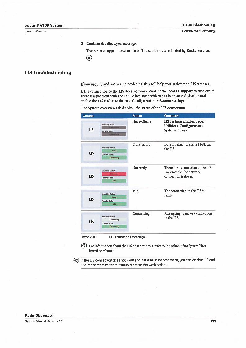
cobas® 4800 System 7 Troubleshooting
Systern Manual General troubleshooting
2 Confirm the displayed message.
The remote support session starts. The session is terminated by Roche Service.
0
LIS troubleshooting
1f you use LIS and are having problems, this will help you understand LIS statuses.
1f the connection to the LIS does not work, contact the local IT support to find out ifthere is a problem with the LIS. When the problem has been solved, disable andenable the LIS under Utilities > Configuration> System settings.
The System overview tab displays the status of the LIS connection.
Screen Status Comment
Not available LIS has been disabled underAb,tyS4s Utilities> Configuration>
LI ts System settings.
Transferring Data is being transferred to/fromthe LIS.
Trarewr5j
Not ready There is no connection to the LIS.For example, the network
LIS Trn,St, connection is down.55e
4Idie The connection to the LIS is
dreay.
Connecting Attempting to make a connectione to the EIS.Ceec5rç
Table 7—6 [IS statuses and meanings
lfJ For information about the LIS host protocols, refer to the cobas 4800 System Host
Interface Manual.
1f the LIS connection does not work and a run must be processed, you can disable LIS and
use the sample editor to manually create the work orders.
Roche Diagnostics
System Manual . Version 1.0 137
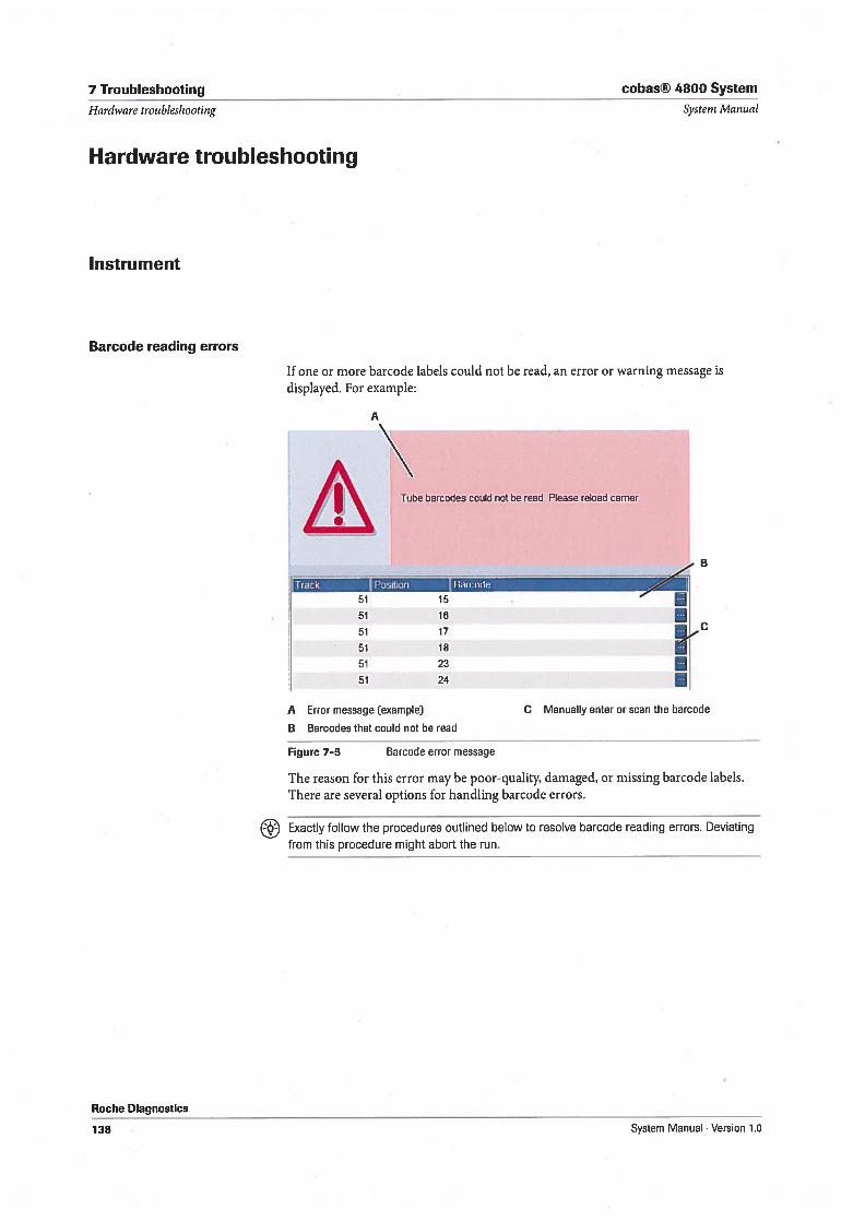
7 Troubleshooting cobas® 4800 System
1f one or more barcode labels could not be read, an error or warning message isdisplayed. For example:
A Error message (example) C Manually enter or scan the barcode
B Barcodes that could not be read
Figure 7-5 Barcode error message
The reason for this error may be poor-quality, damaged, or missing barcode labels.There are several options for handling barcode errors.
E! Exactly follow the procedures outlined below to resolve barcode reading errors. Deviating
from this procedure might abort the run.
Systent Manual
A
Tube barcodes could not be reed Please reload carrier
Hardware troubleshooting
Hardware troubleshooting
Instrument
Barcode reading errors
Roche Diagnostics
Track Position Baicode
51 15
51 16
51 17
51 18
51 23
51 2411
138 System Manual Version 10
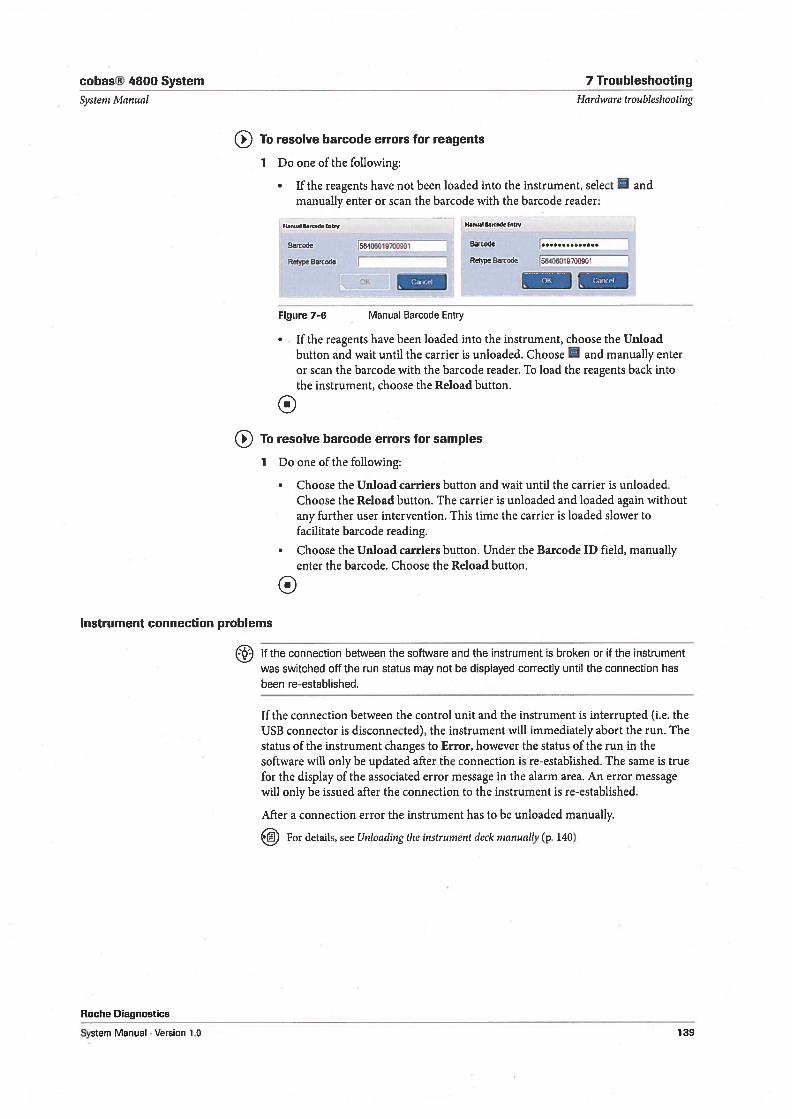
cobas® 4800 System 7 Troubleshooting
Systern Manual Hardware troubleshooting
To resolve barcode errors for reagents
1 Do one of the following:
1f the reagents have not been loaded into the instrument, select andmanually enter or scan the barcode with the barcode reader:
MmI B.d. Entry l1n.t8d £tV
Barod 56406019700901 Barcode
Reqype Barcode Retype Barcode 56406019700901
- 0K1
Figure 7-6 Manual Barcode Entry
1f the reagents have been loaded into the instrument, choose the Unloadbutton and wait until the carrier is unloaded. Choose and manually enteror scan the barcode with the barcode reader. To bad the reagents back intothe instrument, choose the Reload button.
( To resolve barcode errors for samples
1 Do one of the following:
• Choose the Unload carriers button and wait until the carrier is unloaded.Choose the Reload button. The carrier is unloaded and loaded again withoutany further user intervention. This time the carrier is loaded slower tofacilitate barcode reading.
• Choose the Unload carriers button. Under the Barcode ID field, manuallyenter the barcode. Choose the Reload button.
0Instrument connection problems
1f the connection between the software and the instrument is broken or if the instrumentwas switched off the run status may not be displayed correctly until the connection hasbeen re-established.
1f the connection between the control unit and the instrument is interrupted (i.e. theUSB connector is disconnected), the instrument will immediately abort the run. Thestatus of the instrument changes to Error, however the status of the run in thesoftware will only be updated after the connection is re-established. The same is truefor the display of the associated error message in the alarm area. An error messagewill only be issued after the connection to the instrument is re-established.
After a connection error the instrument has to be unloaded manually.
For details, see Unloading the instrument deck nianually (p. 140)
Roche Diagnostics
System Manual . Version 1.0 139
7 Troubleshooting cobas® 4800 System
Hardware troubleshooting System Manual
Run recovery
1f the run control is lost by the software an automatic run recovery process is started.Depending at what time point in a run the run control was lost the recovery processcontinues the run or aborts it. Run control can be lost for reasons like power drops,shutdown of the control unit, or connection or hardware problems.
Results of such runs are flagged with flag M6 (analyzer) or MiO (instrument). Theflag only indicates that run recovery was initiated but does not indicate if the runcould be recovered by the system or not. To decide if the result is reportable analyzethe result itself and all associated flags as you would do with any result.
Remote support
In a remote support session, the software is remotely operated by Roche Service. CallRoche Service to initiate a remote support session.
Do not operate the software during a remote support session.
To initiate a remote support session
1 Request a remote support session at Roche Service.
Roche Service initiates a remote session. A message is displayed on screen askingto allow remote access on this computer.
2 Confirm the displayed message.
The remote support session starts. The session is terminated by Roche Service.
0Unloading the instrument deck manually
All carriers have to be manually unloaded from the instrument deck ifa run wasaborted and the carriers are not automatically unloaded.
Safety information
Take adequate precautions if the instrument deck has to be unloaded manually. Theinstrument deck or the carriers could be contaminated.
Make sure that you have read and understood the chapter General safety information(p. 13). The following safety messages in particular are relevant:
Warning messages:
• Infection by samples and associated materials (p. 19)
• Infection and injury due to sharp objects (p. 19)
Caution messages:
• Skin inflammation orinjuly caused by reagents (p. 21)
To manually unload the instrument after an instrument abort
1 In the wizard, choose the Unload button.
2 1f carriers are not unloaded automatically switch off the instrument.
Roche Diagnostics
140 System Manual . Version 1.0
cobas® 4800 System 7 Troubleshooting
Systeni Manual Hardware troubleshooting
3 Clear all obstructions and remove carefully all carriers from the instrument deck.
Be careful not to break the stop hooks. Unloading carriers manually causes stophooks to break easily.
Call Roche Service ifthere are any obstructions that can not be cleared.
4 Clean the instrument deck.
5 Switch on the instrument.
Check before switching on the instrument that no obstructions are left on theinstrument deck.
6 Perform daily maintenance.
Do not manually remove tips from the pipetting channels. Cail Roche Service ifthere are stili tips on the pipetting channels after daily maintenance.
For details, see Daily maintenance (p. 105)
0Take out of operation
Perform the following take out of operation procedure if the system is not used for alonger period of time.
1 Perform weekly maintenance of the instrument.
For details, see Weekly maintenance(p. 110)
2 Switch off the instrument and unplug the power cord and the USB cable from theinstrument.
3 Switch off the heater / shaker unit and unplug the power cord from the heater /shaker unit.
4 Log off the software, switch off the control unit, and unplug the power cord fromthe control unit.
0
Analyzer
Analyzer connection problems
1f the connection between the control unit and the analyzer is interrupted, the runwill continue and a warning is displayed. After re-connection the software willrefresh the status of the run.
The displayed maintenance status of the analyzer may not be correct. To get thecorrect maintenance status, refresh the analyzer under Overview> System > cobasz480 tab.
Analyzer not working
For error messages and flags, refer to the test-specific Operator’s Manual.
Roche Diagnostics
System Manual . Version 1.0 141
7 Troubleshooting cobas® 4800 System
Hardware troubleshooting Systeni Manual
1f the analyzer does not function
1 Make sure that the analyzer is correctly connected to the power supply.
2 Check if the voltage on the analyzer’s type plate corresponds to the local voltage.
3 1f the analyzer stili does not function, contact Roche Service.
0Red status LEDs
1f the left and right status LEDs glow red
1 Restart the analyzer.
2 1f the LEDs stil! glow red, contact Roche Service.
For error messages and flags, refer to the test-specific Operator’s Manual.
Roche Diagnostics
142 System Manual . Verson 1.0
Glossary

cobas® 4800 System
Systern Manual
Glossary
Arnp4fïcation - Saniple carrier
The glossary explains key terms used in thisdocumentation.
Amplification The process of producing many DNAcopies from one original DNA or RNA target region.PCR is a nucleic acid amplification technique.
Anneal The biochemical process of hybridizing orbinding two segments of complementary nucleic acid.
Autoloader The hardware assembly on the instrumentthat enables automatic loading of carriers placed on theloading deck. It consists of a loading head movable in theY direction, which draws the items into the instrumentand can read the barcodes on them.
Control unit A personal computer that runs theMicrosoft Windows operating system and the software.
Controls Reagent formulated to produce known resuitsthat are processed like samples. The software monitorscontrol resuits. Each run requires a positive and anegative control.
Ct value The amplification/detection cycle where thegrowth curve crosses a specific fluorescence level and thegrowth rate can be observed.
Deepweli plate Plate used for extraction on theinstrument.
Denaturation The process of separating doublestranded DNA into single strands by breaking thehydrogen bonds.
Detection Obtaining measurements to determinewhether a sample is reactive for the target analyte.Fluorescence measurements are made at selectedtemperatures and times during the amplification process.When the run is complete data are analyzed to determinethe presence of the amplified products from the targetand internal control nucleic acid sequences.
DNA Deoxyribonucleic Acid (DNA) is the geneticmaterial that is passed from parent to progeny andpropagates the characteristics of the species in the formof genes it contains and the proteins for which it codes.DNA contains the following four nucleotides: dATP,dCTP, dTTP, and dGTP.
Instrument deck The work surface of the instrument,where pipetting takes place. It is organized as a left-toright series of tracks, into which the autoloader drawscarriers.
LAN Local Area Network. The system control unit iscon nected to the instrument and the analyzer.
Roche Diagnostics
115 Laboratnry information system. A computerizedsystem for entering, managing and reporting laboratoryinformation. Information includes but is not limited topatient demographics, test orders, and test results.
Loading deck The external shelfat the front of theinstrument. It provides a surface onto which carriers canbe placed before the autoloader draws them into theinstrument.
Magnetic glass particles Used in combination withother reagents to bind nucleic acids, allowing separationof impurities during washing.
MGP see Magnetic Glass Particles.
Microweil plate Plate used for amplification anddetection. The 96-well plate is barcoded and has to besealed with a special sealing film before inserting into theanalyzer.
PCR Polymerase Chain Reaction. The in vitro processused to amplify short specific target nucleic acidsequences. PCR is performed by cycling the temperatureof the amplification mixture according to a set profile.The profile generally consists of denaturation andannealing.
Pipetting channel A hardware assembly mounted onthe pipetting arm. It can pick up and eject tips, aspirateand dispense liquid, and detect liquid level in tubes.There are 8 pipetting channels working in parallel.
Pipetting tip A disposable tip for pipetting. The tipsused by the instrument are capable of transferring up to1000 microliters of liquid per pipetting operation. Thetip includes a buik-in filter that prevents the possibilityof liquid inside the tip entering the pipetting channelhardware.
Plate carrier Carrier for deepwell plate and microweilplate on the instrument.
Reagent reservoir The reagent reservoirs hold thereagents used for sample preparation. The reagentreservoirs are barcoded and are filled manually by theoperator (scan-scan-pour-place principle) for each run.Reagent reservoirs are available in two sizes: 200 mL and50 mL.
Sample carrier Used to bad unprocessed samplesonto and to unload processed samples from theinstrument.
System Manual . Version 1.0 145
cobas® 4800 System
Scan-scan-pour-placeprinciple - XML Systern Manual
Scan-scan-pour-place principle To minimizehandling errors the reagent reservoirs are filled andplaced using the scan-scan-pour-place principle.
1. Scan the barcode of the reagent vial. 2. Scan thebarcode of the reagent reservoir. 3. Pour the reagent inthe scanned reagent reservoir. 4. Place the filled reagentreservoir onto the reagent reservoir carrier.
Target The DNA or RNA tatget region that is detectedand amplified during PCR.
Teaching needies Eight titanium pipette tips on theinstrument that are used to automatically check of eachpipetting channel. The teaching needies are stored nearthe waste station, next to the tip waste bag.
Thermal block cycler Programmable temperatureblock in the analyzer. The thermal cycler rapidly changestemperature according to the amplification proffie.
Tip rack The tip racks on the instrument holding thedisposable pipetting tips.
Tip rack carrier The tip rack carriers on theinstrument hold the tip racks with the disposablepipetting tips.
UPS Uninterrupted power supply.
XMI Extensible Markup Language.
Roche Diagnostics
146 System Manual . Version 1.0

Index

cobas® 4800 System
Systern Manual
Index
Index
A
abbreviations, 8alarms— confirming, 132—tab, 131— viewing, 132approvals, 2archiving— parameters, 91— settings, 90—tab, 90audit trail, 81autofilter, 78autoload unit, 43
— overview, 35—x480, 58,64—z480, 68contact addresses, 3context menus, 77control unit, 69controls, specifications, 62conventions used in manual, 7copyrights, 2covers, x 480, 40creating— problem report, 136cross contamination, 22
D
B
barcode reader, handheld, 69barcodes— reading errors, 138basic software elements, 73biohazardous materials, 19block cycler unit, 65buttons— concepts, 75— global action, 75
c
carriers—plates, 55— reagents, 53— stationary, 56— tip racks, 55—x480, 50carryover, 22CFR, 81,82changing— passwords, 92— user accounts, 95circuit breakers, 24cleaning—x480, 105—z480, 115colors in user interface, 74column header context menus, 77columns, displaying and hiding, 77confirming alarms, 132connection errors, 139, 141consumables— for waste, 61
Roche Diagnostics
daily maintenance, for x 480, 105data security, 23database, 81deepwell plates, 59defining— user accounts, 94definitions, see settingsdeleting— user accounts, 95detection unit, 65dimensions—x480, 62—z480, 67disabling tests, 89displaying— columns, 77—flags, 134disposing— analyzer, 27—fluidwaste, 108, 114—waste, 19document information, 2dust filters, 119
E
editing, see changingedition notice, 2electrical safety, 18enabling tests, 89environmental conditions—x480, 62—z480, 68errors— connecting, 139, 141— reading barcodes, 138
System Manual . Version 1.0 149
Index cobas® 4800 System
Systern Mcrnual
evaporation of samples, 21exchanging—fusesonz480, 122—ventilation dust filters on z 480, 119—xenon lamp on z 480, 116explosion, safety, 20exporting— support data, 97
F
filtering information— advanced features, 79— autofilter, 78— drop-down list, 78filters, for dust, 119fire, safety, 20flags— displaying, 134fluid waste, disposing, 108, 114fuses— exchanging on z 480, 122— safety, 24
installation, 16—x480, 62instrument approvals, 2instrument deck, x 480, 41intended use, 2interfaces—x480, 63—z480, 68ISWAP, 46
1
labels, 25LEDs—x480, 41—z480, 67LIS, 34LIS statuses, 137lists— advanced filtering, 79— filtering, 79— organizing, 76— sorting, 77— use, 76
M
magnet plate, 57maintenance— daily for x 480, 105—weeklyforx 480, 110—x480, 104—z480, 115managing— passwords, 92— user accounts, 93Manual—version, 2measurements—x480, 62—z480, 68messages, 131—work area, 131microwell plates, 60
0
operating con ditions, 16operator qualifications, 16optical safety, 18overview— cobas 4800 user interface, 73— cobas x 480, 32, 39—cobasz480, 33,65— control unit, 34— system, 31
p
passwords— changing, 92— managing, 92— rules, 96physical dimensions, 67—x480, 62
G
general cleaning—x480, 105—z480, 115global action buttons, 75
H
hardware, 37—x480, 39—z480, 65heater unit, 56heater/shaker unit— specifications, 64hiding columns, 77
Roche Diagnostics
150 System Manual . Version 1.0
cobas® 4800 System Index
Systern Manual
—z480, 67pipetting arm, x 480, 45plate carriers, 55plates— deepweil, 59— microweli, 60power requirements—x480, 62—z480, 67precautions, 16principles—x480, 62—z480, 68problem reports, 136product names, 9protective equipment, 16
Q
qualifications, 16
R
reading errors, 138reagent carriers, 53reagent reservoirs, 58reagents— carriers, 53remote support, 136, 140replacing—fusesonz480, 122— ventilation dust filters on z 480, 119—waste bags, 107, 111—xenon lamp on z480, 116reporting, 88reports— for problems, 136result counters, 98result flags, see flagsresult icons, 134resuits—accuracy, 16retrieving— problem report, 136reviewing— alarms, 132revision history, 2rules— for passwords, 96— for user accounts, 96run recovery, 140
S
safety
Roche Diagnostics
System Manual Version 1.0
— biohazards, 19— carryover, 22— data security, 23— disposal of analyzer, 27— disposal of instrument, 27— electrical, 18— electromagnetic fields, 17— explosion, 20— fire, 20— fuses, 24— hot surfaces, 22— incorrect results, 22— labels, 25— labels on the system, 25— moving parts, 20— operating conditions, 16— optical, 18— power failure, 17—precautions, 16— result accuracy, 16—samples, 21—use, 16—waste, 19safety classification, 15sample carriers, x 480, 50samples—safety, 21— specifications, 62sealing film, 60settings, for archiving, 90shaker unit, 56software version, 2sorting list entries, 77stationary carrier, 56support data, 97symbols, 7system— settings cobas 4800, 87
T
tabs— Alarms, 131— Audit trail, 81— Configuration, 87— Export support data, 97— in user interface, 74— Messages, 132— Users, 93— Workpiace, 74taking Out of operation, 141teaching needles, x 480, 46technical specifications—x480, 61—z480, 67tests
151
Index cobas® 4800 System
Systeni Manual
— disabling, 89— enabling, 89third-party software, 17tip rack carriers, 55track positions, x 480, 42trademarks, 2
u
unloading— x 480 manually, 140unlocking user accounts, 95use of manual, 7user accounts—changing, 95— defining, 94— deleting, 95— management, 93—rules, 96— unlocking, 95user interface— colors, 74—lists, 76—tabs, 74user management, 92
—LEDs, 41— maintenance, 104— manual unloading, 140— pipetting arm, 45— sample carriers, 50— teaching needies, 46— technical specifications, 61— track pos itions, 42— waste container, 48— waste station, 47xenon lamp, exchanging on z 480, 116
z
z480, 65— block cycler unit, 65— detection unit, 65— LEDs, 67— technical specifications, 67
1
ventilation dust filters, exchanging on Z 480, 119
w
waste— consumables, 61— emptying fluids, 108, 114— replacing bags, 107, 111—safety, 19—x480, 63waste bags, replacing, 107, 111waste container, x 480, 48waste station, x 480, 47weekly maintenance, for x 480, 110wizards, 80
x
x480, 39— autoload unit, 43— carriers, 50— consumables, 58— covers, 40— heater/shaker unit, 56— instrument deck, 41—ISWAP, 46
Roche Diagnosties
152 System Manual . Version 1.0
Revisions