Embed Size (px)
Citation preview
System ManualMEDIUM VOLTAGE STATION 600 / 1200 / 1800for SUNNY TRIPOWER 60
MVS-STP-SH-A1-en-10 | 101749-00.01 | Version 1.0ENGLISH
Table of Contents1 Information on this Document..................................................................................................... 5
1.1 Validity ............................................................................................................................................................. 51.2 Target Group ................................................................................................................................................... 51.3 Additional Information..................................................................................................................................... 51.4 Symbols............................................................................................................................................................ 51.5 Typographies ................................................................................................................................................... 61.6 Nomenclature .................................................................................................................................................. 6
2 Safety ............................................................................................................................................ 72.1 Intended Use.................................................................................................................................................... 72.2 Safety Information ........................................................................................................................................... 82.3 Personal Protective Equipment ........................................................................................................................ 10
3 Product Overview ........................................................................................................................ 123.1 System Overview............................................................................................................................................. 123.2 Design of the MV Station ................................................................................................................................ 133.3 Operating and Display Elements.................................................................................................................... 14
3.3.1 Control Elements in the Low-Voltage Compartment....................................................................................... 143.3.2 Control Elements in the Medium-Voltage Compartment................................................................................ 153.3.3 MV Transformer Hermetic Full-Protection Device ........................................................................................... 15
4 Transport and Mounting.............................................................................................................. 174.1 Safety during Transport and Mounting .......................................................................................................... 174.2 Requirements for Transport and Mounting .................................................................................................... 17
4.2.1 Requirements for Transport Routes and Means of Transport ........................................................................ 174.2.2 Center of Gravity Marker ................................................................................................................................ 18
4.3 Transport by truck or ship................................................................................................................................ 184.4 Transporting the MV Station Using a Crane.................................................................................................. 194.5 Removing the Supplied Mounting Material from the MV Station ................................................................ 204.6 Removing the Quick Tie Connectors .............................................................................................................. 214.7 Transporting the MV Station Using a Forklift ................................................................................................. 224.8 Mounting the Support Feet on the MV Station.............................................................................................. 234.9 Mounting the MV Station................................................................................................................................ 244.10 Adjusting the Height of the Support Feet ....................................................................................................... 25
5 Installation .................................................................................................................................... 275.1 Safety during Installation................................................................................................................................. 275.2 Installation Sequence ...................................................................................................................................... 285.3 Preparatory Work............................................................................................................................................ 29
5.3.1 Removing the Sealing Plates in front of the MV Transformer ........................................................................ 295.3.2 Removing the transport lock ............................................................................................................................ 295.3.3 Removing the Desiccant Bag from the Station Container.............................................................................. 305.3.4 Working in the Medium-Voltage Compartment ............................................................................................. 305.3.5 Working in the Low-Voltage Compartment .................................................................................................... 30
5.4 Installing the Grounding on the Station Container ........................................................................................ 315.5 Installing the Low-Voltage Connection ........................................................................................................... 335.6 Medium-Voltage Connection .......................................................................................................................... 35
5.6.1 Making the Medium-Voltage Connection to the MV Switchgear................................................................. 35
Table of Contents SMA Solar Technology AG
System ManualMVS-STP-SH-A1-en-102
5.6.2 Making the Medium-Voltage Connection to the MV Transformer................................................................ 365.7 Connecting the Communication Network...................................................................................................... 385.8 Requirements for Commissioning.................................................................................................................... 39
6 Disconnecting and Reconnecting ................................................................................................ 416.1 Safety When Disconnecting and Reconnecting Voltage Sources ................................................................ 416.2 Disconnecting the MV Station From Voltage Sources................................................................................... 426.3 Reconnecting the MV Station ......................................................................................................................... 42
7 Troubleshooting............................................................................................................................ 447.1 Safety during Troubleshooting........................................................................................................................ 447.2 Troubleshooting in the Medium-Voltage Compartment ................................................................................ 447.3 Troubleshooting in the Low-Voltage Compartment........................................................................................ 46
8 Maintenance................................................................................................................................. 478.1 Safety during Maintenance ............................................................................................................................ 478.2 Maintenance Schedule for Qualified Persons and Consumables................................................................ 49
8.2.1 Information on Maintenance........................................................................................................................... 498.2.2 Servicing Schedule for General Work............................................................................................................ 498.2.3 Servicing Schedule for Work on the Station Container................................................................................. 508.2.4 Servicing Schedule for Work on the MV Transformer ................................................................................... 508.2.5 Servicing Schedule for Work in the Medium-Voltage Compartment............................................................ 518.2.6 Servicing Schedule for Work on the MV Switchgear .................................................................................... 518.2.7 Servicing Schedule for Work on the Station Subdistribution......................................................................... 528.2.8 Servicing Schedule for Work on the Oil Tray ................................................................................................ 52
8.3 Maintenance Work ......................................................................................................................................... 538.3.1 General Maintenance Work........................................................................................................................... 53
8.3.1.1 Maintaining the Seals ..................................................................................................................................... 538.3.1.2 Performing the Visual Inspection .................................................................................................................... 538.3.1.3 Checking the Latches, Door Stops and Hinges............................................................................................. 548.3.1.4 Cleaning the Interior ....................................................................................................................................... 558.3.1.5 Checking the Labels........................................................................................................................................ 55
8.3.2 Maintenance Work on the MV Transformer .................................................................................................. 558.3.2.1 Checking the Oil Level at the Hermetic Full-Protection Device..................................................................... 558.3.2.2 Checking the Cooling Surfaces for Dirt and Damages ................................................................................ 568.3.2.3 Checking the Seals on the MV Transformer.................................................................................................. 568.3.2.4 Checking the Low-Voltage Connection.......................................................................................................... 568.3.2.5 Checking Electrical Connections for Dirt and Signs of Electric Arcs............................................................ 568.3.2.6 Checking Torque of the Grounding Connection........................................................................................... 578.3.2.7 Checking the Oil Temperature at the Hermetic Full-Protection Device ........................................................ 578.3.2.8 Checking the Function of the Control Elements of the Hermetic Full-Protection Device.............................. 58
8.3.3 Maintenance Work in the Medium-Voltage Compartment ........................................................................... 598.3.3.1 Checking Grounding Connections................................................................................................................. 59
8.3.4 Maintenance Work on the MV Switchgear ................................................................................................... 598.3.4.1 Checking the MV Switchgear's Level of Gas ................................................................................................ 598.3.4.2 Checking the Internal Arc Pressure Relief ...................................................................................................... 608.3.4.3 Checking Functionality of the Circuit Breaker ............................................................................................... 608.3.4.4 Checking Electrical Connections.................................................................................................................... 608.3.4.5 Checking the Alignment of the Switch Position Indicators............................................................................ 608.3.4.6 Replacing the Voltage Indicator .................................................................................................................... 61
8.3.5 Completion of the Maintenance Work........................................................................................................... 61
9 Disposal......................................................................................................................................... 62
Table of ContentsSMA Solar Technology AG
System Manual 3MVS-STP-SH-A1-en-10
10 Periodic Actions ............................................................................................................................ 6310.1 Opening and Closing the Doors of the Station Container............................................................................ 6310.2 Erecting and Stowing the Service Platform in front of the Medium-Voltage Compartment ........................ 6410.3 Disassembling and Mounting the Kick Plate of the MV Switchgear ............................................................ 6710.4 Mounting and Removing the Grids in front of the MV Transformer ............................................................. 67
11 Technical Data .............................................................................................................................. 6911.1 MV Station 600 STP........................................................................................................................................ 6911.2 MV Station 1200 STP ..................................................................................................................................... 7011.3 MV Station 1800 STP ..................................................................................................................................... 71
12 Appendix ...................................................................................................................................... 7212.1 Ambient Conditions ......................................................................................................................................... 7212.2 Minimum Clearances ...................................................................................................................................... 7312.3 Recesses in the Support Surface..................................................................................................................... 7312.4 External dimensions and weights ................................................................................................................... 7512.5 Scope of Delivery ............................................................................................................................................ 75
13 Contact .......................................................................................................................................... 77
Table of Contents SMA Solar Technology AG
System ManualMVS-STP-SH-A1-en-104
1 Information on this Document
1.1 ValidityThis document is valid for the following device types:
Device type Production version
MV Station 600 for Sunny Tripower 60(MVS-600-STP-10)MV Station 1200 for Sunny Tripower 60(MVS-1200-STP-10)MV Station 1800 for Sunny Tripower 60(MVS-1800-STP-10)
1.0
The production version of the MV Station is indicated on the type label.Illustrations in this document are reduced to the essential and may deviate from the real product.
1.2 Target GroupThe tasks described in this document must only be performed by qualified persons. Qualified persons must have thefollowing skills:
• Knowledge of how the product works and is operated• Training in how to deal with the dangers and risks associated with installing and using electrical devices and
systems• Training in the installation and commissioning of electrical devices and systems• Knowledge of all applicable standards and directives• Knowledge of and adherence to this manual and all safety precautions
1.3 Additional InformationLinks to additional information can be found at www.SMA-Solar.com.
1.4 SymbolsSymbol Explanation
Indicates a hazardous situation which, if not avoided, will result in death or serious injury
Indicates a hazardous situation which, if not avoided, can result in death or serious injury
Indicates a hazardous situation which, if not avoided, can result in minor or moderate injury
Indicates a situation which, if not avoided, can result in property damage
Information that is important for a specific topic or goal, but is not safety-relevant
Indicates a requirement for meeting a specific goal
Desired result
A problem that might occur
1 Information on this DocumentSMA Solar Technology AG
System Manual 5MVS-STP-SH-A1-en-10
1.5 TypographiesTypographies Use Example
bold • Display messages• Elements on a user interface• Terminals• Slots• Elements to be selected• Elements to be entered
• Set parameter WGra to 0.2.
> • Connects several elements to beselected
• Select PV system > Detect.
[Button/Key] • Button or key to be selected orpressed
• Select [Start detection].
1.6 NomenclatureComplete designation Designation in this document
Sunny Tripower 60STP 60-10
Sunny Tripower or inverter
MV Station for Sunny TripowerMVS-600-STP-10MVS-1200-STP-10MVS-1800-STP-10
MV Station
Medium-voltage switchgear MV switchgear
Medium-voltage transformer MV transformer
1 Information on this Document SMA Solar Technology AG
System ManualMVS-STP-SH-A1-en-106
2 Safety
2.1 Intended UseThe MV Station is a system for PV power plants which transforms the alternating current supplied by the inverters forfeeding into the medium-voltage grid. All devices required to feed the alternating current generated by the invertersinto the medium-voltage grid are installed in the MV Station. Depending on the order option, the MV Station can alsomonitor and control the connected inverters with an Inverter Manager.Operation of the MV Station is only permitted providing that the maximum permissible input voltage, output voltageand the permitted ambient conditions are adhered to. The configuration of the MV Station determines the respectivepermissible output voltage (medium voltage) and the permissible ambient conditions. Ensure that the ambientconditions and the maximum permissible voltages are complied with prior to commissioning the MV Station.It is only permitted to use the product in a PV power plant which is designed as a closed electrical operating area asper IEC 61936-1.The specified safety clearances must be observed.Do not deactivate or modify settings that affect grid management services without first obtaining approval from the gridoperator.The product is designed for outdoor use only.Use this product only in accordance with the information provided in the enclosed documentation and with the locallyapplicable standards and directives. Any other application may cause personal injury or property damage.Alterations to the product, e.g. changes or modifications, are only permitted with the express written permission ofSMA Solar Technology AG. Unauthorized alterations will void guarantee and warranty claims and in most casesterminate the operating license. SMA Solar Technology AG shall not be held liable for any damage caused by suchchanges.Any use of the product other than that described in the Intended Use section does not qualify as appropriate.The enclosed documentation is an integral part of this product. Keep the documentation in a convenient place forfuture reference and observe all instructions contained therein.Only persons fulfilling all of the skills for the target group are permitted to work on or with the product.All work on the product must only be performed using appropriate tools and in compliance with the ESD protectionregulations.Suitable personal protective equipment has to be worn by all persons working on or with the product.Unauthorized persons must not operate the product and must be kept at a safe distance from the product.The lattice doors in front of the MV transformer must be closed during operation.The low-voltage compartment may not be opened during rain or in dusty conditions.The product must not be operated with any technical defects.The type label must remain permanently attached to the product.
2 SafetySMA Solar Technology AG
System Manual 7MVS-STP-SH-A1-en-10
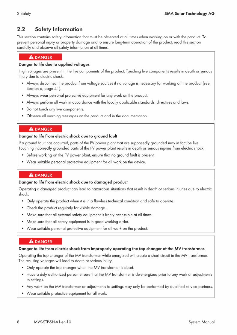
2.2 Safety InformationThis section contains safety information that must be observed at all times when working on or with the product. Toprevent personal injury or property damage and to ensure long-term operation of the product, read this sectioncarefully and observe all safety information at all times.
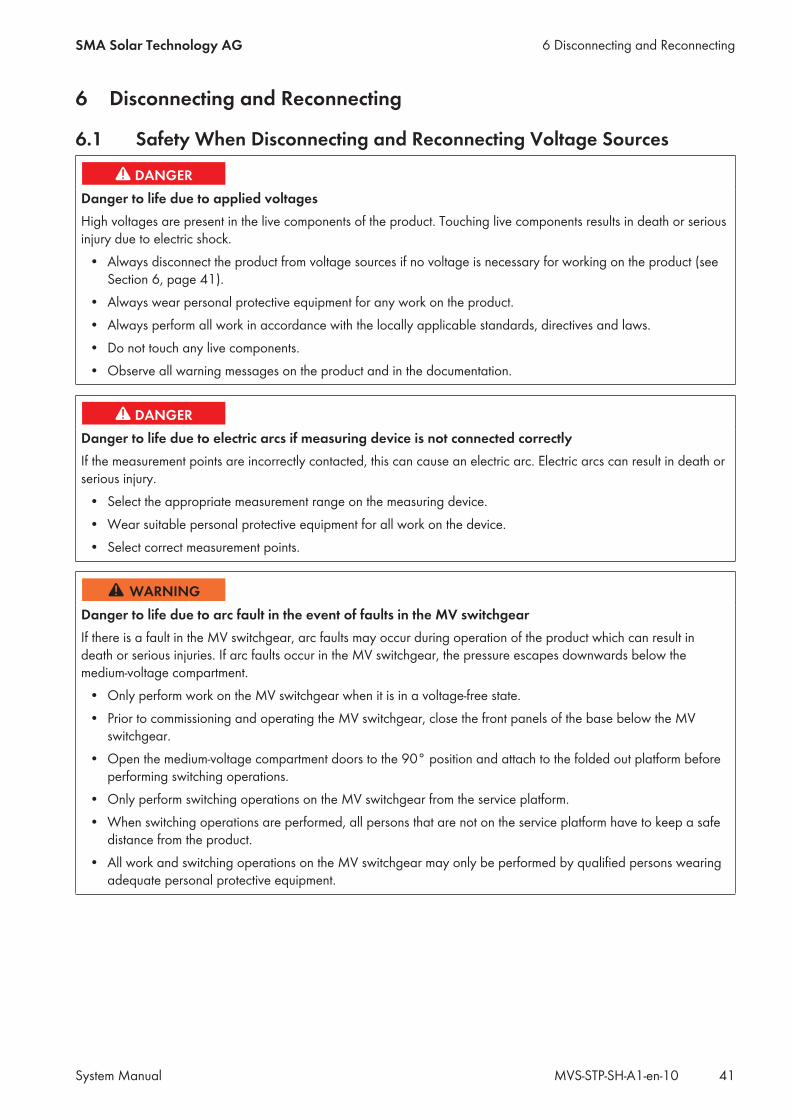
Danger to life due to applied voltagesHigh voltages are present in the live components of the product. Touching live components results in death or seriousinjury due to electric shock.
• Always disconnect the product from voltage sources if no voltage is necessary for working on the product (seeSection 6, page 41).
• Always wear personal protective equipment for any work on the product.• Always perform all work in accordance with the locally applicable standards, directives and laws.• Do not touch any live components.• Observe all warning messages on the product and in the documentation.
Danger to life from electric shock due to ground faultIf a ground fault has occurred, parts of the PV power plant that are supposedly grounded may in fact be live.Touching incorrectly grounded parts of the PV power plant results in death or serious injuries from electric shock.
• Before working on the PV power plant, ensure that no ground fault is present.• Wear suitable personal protective equipment for all work on the device.
Danger to life from electric shock due to damaged productOperating a damaged product can lead to hazardous situations that result in death or serious injuries due to electricshock.
• Only operate the product when it is in a flawless technical condition and safe to operate.• Check the product regularly for visible damage.• Make sure that all external safety equipment is freely accessible at all times.• Make sure that all safety equipment is in good working order.• Wear suitable personal protective equipment for all work on the product.
Danger to life from electric shock from improperly operating the tap changer of the MV transformer.Operating the tap changer of the MV transformer while energized will create a short circuit in the MV transformer.The resulting voltages will lead to death or serious injury.
• Only operate the tap changer when the MV transformer is dead.• Have a duly authorized person ensure that the MV transformer is de-energized prior to any work or adjustments
to settings.• Any work on the MV transformer or adjustments to settings may only be performed by qualified service partners.• Wear suitable protective equipment for all work.
2 Safety SMA Solar Technology AG
System ManualMVS-STP-SH-A1-en-108
Danger to life from electric shock if the product is not lockedIf the product is not locked, unauthorized persons will have access to live components carrying lethal voltages.Touching live components can result in death or serious injury due to electric shock.
• Always close and lock the product.• Remove the keys.• Store the keys in a safe place.• Ensure that no unauthorized persons have access to the closed electrical operating area.
Risk of fire due to failure to observe torque specifications on live bolted connectionsFailure to follow the specified torques reduces the ampacity of live bolted connections so that the contact resistancesincrease. This can cause components to overheat and catch fire.
• Ensure that live bolted connections are always tightened with the exact torque specified in this document.• When working on the device, use suitable tools only.• Avoid repeated tightening of live bolted connections as this may result in inadmissibly high torques.
Danger to life due to arc fault in the event of faults in the MV switchgearIf there is a fault in the MV switchgear, arc faults may occur during operation of the product which can result indeath or serious injuries. If arc faults occur in the MV switchgear, the pressure escapes downwards below themedium-voltage compartment.
• Only perform work on the MV switchgear when it is in a voltage-free state.• Prior to commissioning and operating the MV switchgear, close the front panels of the base below the MV
switchgear.• Open the medium-voltage compartment doors to the 90° position and attach to the folded out platform before
performing switching operations.• Only perform switching operations on the MV switchgear from the service platform.• When switching operations are performed, all persons that are not on the service platform have to keep a safe
distance from the product.• All work and switching operations on the MV switchgear may only be performed by qualified persons wearing
adequate personal protective equipment.
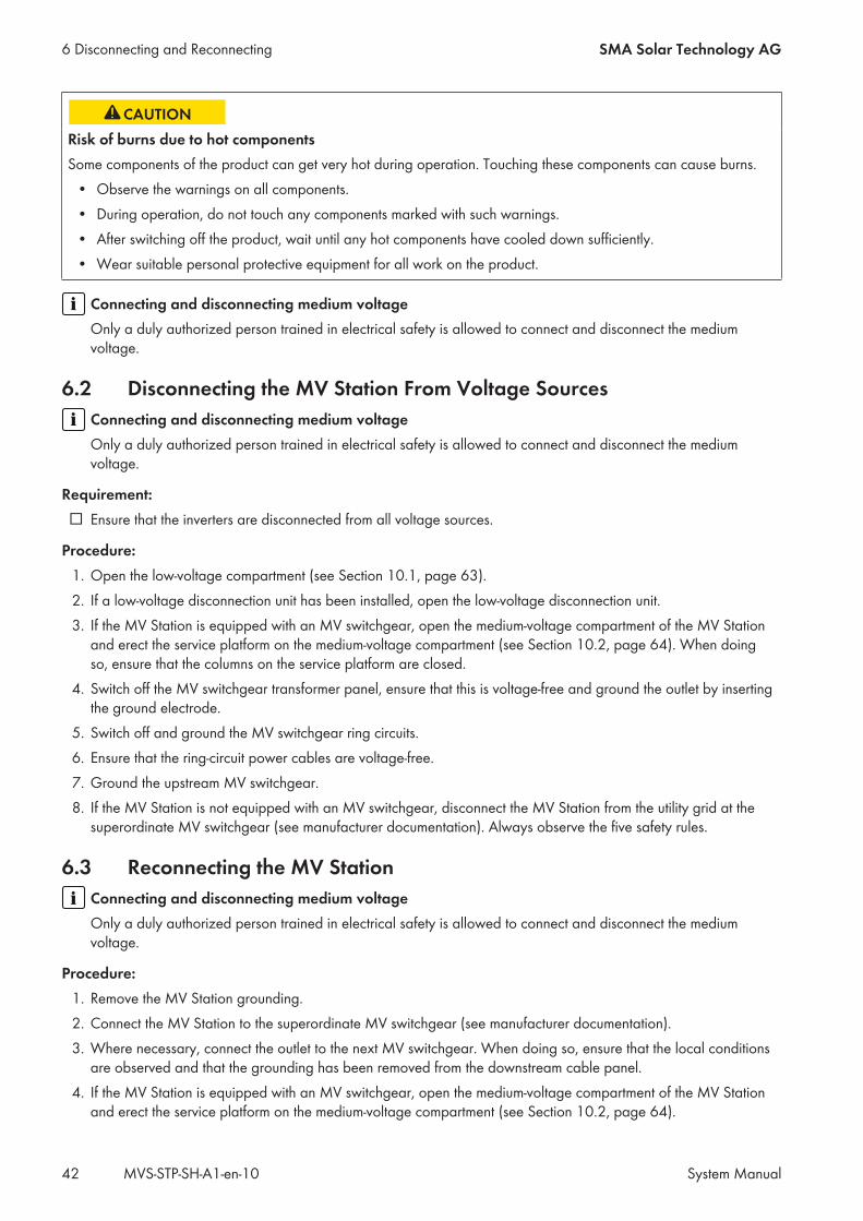
Risk of burns due to hot componentsSome components of the product can get very hot during operation. Touching these components can cause burns.
• Observe the warnings on all components.• During operation, do not touch any components marked with such warnings.• After switching off the product, wait until any hot components have cooled down sufficiently.• Wear suitable personal protective equipment for all work on the product.
2 SafetySMA Solar Technology AG
System Manual 9MVS-STP-SH-A1-en-10
Danger of poisoning through SF6 gas residuesAfter a fire in the MV switchgear, SF6 gas residues will be present in the surroundings of the MV switchgear. Theseresidues can result in poisoning.
• After a fire in the MV switchgear, have a professional disposal contractor remove the SF6 gas residues presentin the surroundings of the MV switchgear.
• Only recommission the system once these residues have been removed.
Damage to the devices due to sand, dust or moisture penetrationSand, dust or moisture penetration can damage the devices of the MV Station or impair their functionality.
• Do not open any devices during a sandstorm, precipitation or when humidity exceeds 95%.• Only perform maintenance work when the environment is dry and free of dust.• If the installation, maintenance or commissioning process is interrupted, mount all enclosure parts and close all
doors.
Damage to electronic components due to electrostatic dischargeElectrostatic discharge can damage or destroy electronic components.
• Observe the ESD safety regulations when working on the product.• Wear suitable personal protective equipment for all work on the product.• Discharge electrostatic charge by touching grounded enclosure parts or other grounded elements. Only then is
it safe to touch electronic components.
Damage to the oil tray due to iceWater in the oil tray can freeze at low temperatures and damage the oil tray.
• Check the oil tray regularly for water. Remove water, if necessary.
2.3 Personal Protective EquipmentAlways wear suitable protective equipmentWhen working on the product, always wear the appropriate personal protective equipment for the specific job.
The following personal protective equipment is regarded to be the minimum requirement:☐ In a dry environment, safety shoes of category S3 with perforation-proof soles and steel toe caps☐ During precipitation or on moist ground, safety boots of category S5 with perforation-proof soles and steel toe
caps☐ Tight-fitting work clothes made of 100% cotton☐ Suitable work pants☐ Proper hearing protection☐ Safety gloves☐ Proper head protection
2 Safety SMA Solar Technology AG
System ManualMVS-STP-SH-A1-en-1010
Always wear suitable protective equipment when performing switching operations on the MV switchgear. The requiredprotective equipment must comply with the national regulations.Any other prescribed protective equipment must also be used.
2 SafetySMA Solar Technology AG
System Manual 11MVS-STP-SH-A1-en-10
3 Product Overview
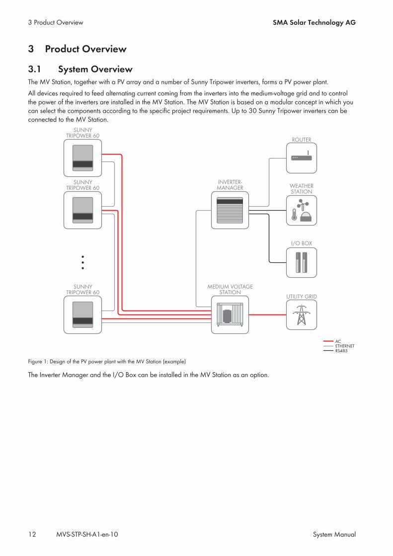
3.1 System OverviewThe MV Station, together with a PV array and a number of Sunny Tripower inverters, forms a PV power plant.All devices required to feed alternating current coming from the inverters into the medium-voltage grid and to controlthe power of the inverters are installed in the MV Station. The MV Station is based on a modular concept in which youcan select the components according to the specific project requirements. Up to 30 Sunny Tripower inverters can beconnected to the MV Station.
SUNNYTRIPOWER 60
INVERTER-MANAGER
SUNNYTRIPOWER 60
SUNNYTRIPOWER 60
MEDIUM VOLTAGESTATION
ROUTER
ACETHERNETRS485
WEATHERSTATION
I/O BOX
UTILITY GRID
Figure 1: Design of the PV power plant with the MV Station (example)
The Inverter Manager and the I/O Box can be installed in the MV Station as an option.
3 Product Overview SMA Solar Technology AG
System ManualMVS-STP-SH-A1-en-1012
3.2 Design of the MV Station
A
B
D
C
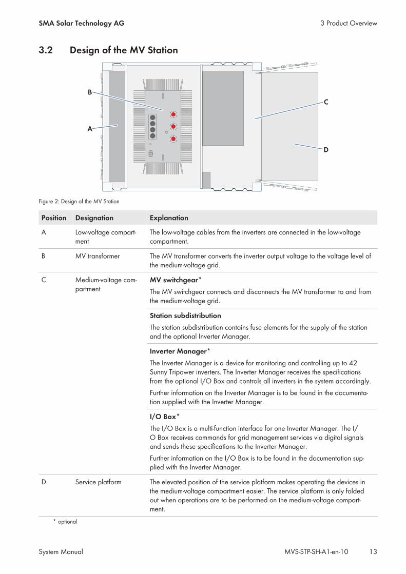
Figure 2: Design of the MV Station
Position Designation Explanation
A Low-voltage compart-ment
The low-voltage cables from the inverters are connected in the low-voltagecompartment.
B MV transformer The MV transformer converts the inverter output voltage to the voltage level ofthe medium-voltage grid.
C Medium-voltage com-partment
MV switchgear*The MV switchgear connects and disconnects the MV transformer to and fromthe medium-voltage grid.
Station subdistributionThe station subdistribution contains fuse elements for the supply of the stationand the optional Inverter Manager.
Inverter Manager*The Inverter Manager is a device for monitoring and controlling up to 42Sunny Tripower inverters. The Inverter Manager receives the specificationsfrom the optional I/O Box and controls all inverters in the system accordingly.Further information on the Inverter Manager is to be found in the documenta-tion supplied with the Inverter Manager.
I/O Box*The I/O Box is a multi-function interface for one Inverter Manager. The I/O Box receives commands for grid management services via digital signalsand sends these specifications to the Inverter Manager.Further information on the I/O Box is to be found in the documentation sup-plied with the Inverter Manager.
D Service platform The elevated position of the service platform makes operating the devices inthe medium-voltage compartment easier. The service platform is only foldedout when operations are to be performed on the medium-voltage compart-ment.
* optional
3 Product OverviewSMA Solar Technology AG
System Manual 13MVS-STP-SH-A1-en-10
3.3 Operating and Display Elements
3.3.1 Control Elements in the Low-Voltage Compartment
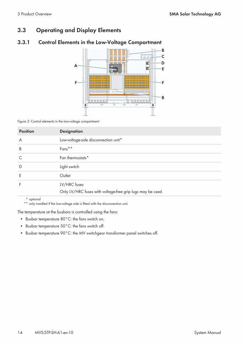
Figure 3: Control elements in the low-voltage compartment
Position Designation
A Low-voltage-side disconnection unit*
B Fans**
C Fan thermostats*
D Light switch
E Outlet
F LV/HRC fusesOnly LV/HRC fuses with voltage-free grip lugs may be used.
* optional** only installed if the low-voltage side is fitted with the disconnection unit.
The temperature at the busbars is controlled using the fans:• Busbar temperature 80°C: the fans switch on.• Busbar temperature 50°C: the fans switch off.• Busbar temperature 90°C: the MV switchgear transformer panel switches off.
3 Product Overview SMA Solar Technology AG
System ManualMVS-STP-SH-A1-en-1014
3.3.2 Control Elements in the Medium-Voltage Compartment
B
A
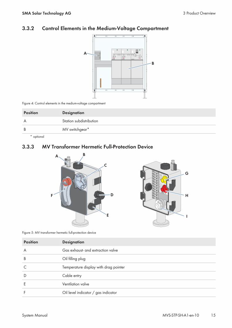
Figure 4: Control elements in the medium-voltage compartment
Position Designation
A Station subdistribution
B MV switchgear** optional
3.3.3 MV Transformer Hermetic Full-Protection Device
Figure 5: MV transformer hermetic full-protection device
Position Designation
A Gas exhaust- and extraction valve
B Oil filling plug
C Temperature display with drag pointer
D Cable entry
E Ventilation valve
F Oil level indicator / gas indicator
3 Product OverviewSMA Solar Technology AG
System Manual 15MVS-STP-SH-A1-en-10
Position Designation
G Rotary potentiometer "Warning temperature"
H Rotary potentiometer "Disconnection temperature"
I Control dial "Oil pressure"
The hermetic full-protection device monitors amongst other things the temperature of the transformer oil.If the transformer oil temperature exceeds the value set for the warning temperature, the hermetic full-protection deviceissues a signal. This signal can be fed to the Inverter Manager or to another communication interface provided by thecustomer. Information on which terminals are to be used for connection to the communication interface is to be foundin the circuit diagram. The warning temperature is set to 90°C.If the transformer oil temperature exceeds the value set for the disconnection temperature, the MV transformerdisconnects the MV switchgear transformer panel. This switches the MV transformer and the inverter off. Thedisconnection temperature is set to 100 C.
3 Product Overview SMA Solar Technology AG
System ManualMVS-STP-SH-A1-en-1016
4 Transport and Mounting
4.1 Safety during Transport and Mounting
Danger of crushing if raised or suspended loads tip over, fall or swayVibrations or careless or hasty lifting and transportation may cause loads to tip over or fall. This can result in death orserious injury.
• Follow all national transportation standards and regulations.• Never allow anyone to walk or stand under a suspended load at any time.• Always transport the load as close to the ground as possible.• Use all suspension points for transportation.• Use the tie-down and crane points provided for transportation.• Avoid fast or jerky movements during transport.• Always maintain an adequate safety distance during transport.• All means of transport and auxiliary equipment used must be designed for the weight of the load.• Wear suitable personal protective equipment for all work on the product.
Danger of crushing and collision when carelessly working on the productCarelessly working on the product could result in crushing injuries or collisions with edges.
• Wear personal protective equipment for all work on the product.
Damage to the frame construction due to uneven support surfaceIf the product is set down on uneven surfaces, components may distort. This may lead to moisture and dustpenetration into the components.
• Never place the product on an unstable, uneven surface; not even for a short period of time.• The unevenness of the support surface must be less than 0.25%.• The support surface must be suitable for the weight of the product.• Prior to storage, ensure that the doors of the product are tightly closed.
Wash the closed station container with fresh water after maritime transport.High humidity and salt water can cause corrosion of the station container during maritime transport. It isrecommended to clean the station container with clear water prior to installation. This will inhibit the corrosionprocess. Coat the affected areas in order to prevent further corrosion.
4.2 Requirements for Transport and Mounting
4.2.1 Requirements for Transport Routes and Means of Transport☐ The maximum permissible gradient of the access road is 4%.☐ During unloading, a distance of at least 2 m to neighboring obstacles must be observed.☐ The access road must be constructed to ensure that a truck (16 m long, 2.70 m wide, 5 m high, and a total weight
of 50 t) can reach the unloading site. The curve radius of the truck must be taken into account.
4 Transport and MountingSMA Solar Technology AG
System Manual 17MVS-STP-SH-A1-en-10
☐ Transport must be carried out by truck with air-sprung chassis.☐ For trucks with several containers, the access roads and the unloading site must be designed corresponding to the
length, width, height, total weight and curve radius of the truck.☐ The unloading site for the crane and truck must be firm, dry and horizontal.
4.2.2 Center of Gravity MarkerThe center of gravity of the MV Station is not in the middle. Take this into consideration when transporting theMV Station. The center of gravity depends on the power class of the MV Station.The center of gravity of the MV Station is marked on the station container.
Figure 6: Center of gravity symbol
4.3 Transport by truck or shipThe dimensions and shape of the MV Station correspond to those of an ISO container. This means that it can beloaded, secured for transport, transported and installed quickly and easily. It can be transported via truck or ship. Atruck 16 m long, 2.7 m wide, 5 m high, and with a total weight of 50 t can transport up to four MV Stations. Fortransport, two MV stations each can be coupled together using special coupling elements.Transport via airfreight or railroad is not permitted.During transport and unloading, damage to the paint of the station container may occur. Damage to the paint doesnot impair the function of the MV Station. However, any damage must be remedied using the spare paint suppliedwithin three weeks at the latest.For transportation by truck or ship, the MV Station must be secured at least at all four lower corner castings. This canbe done by various methods, depending on the fastening system of the means of transportation. The most commonmethods are described below.
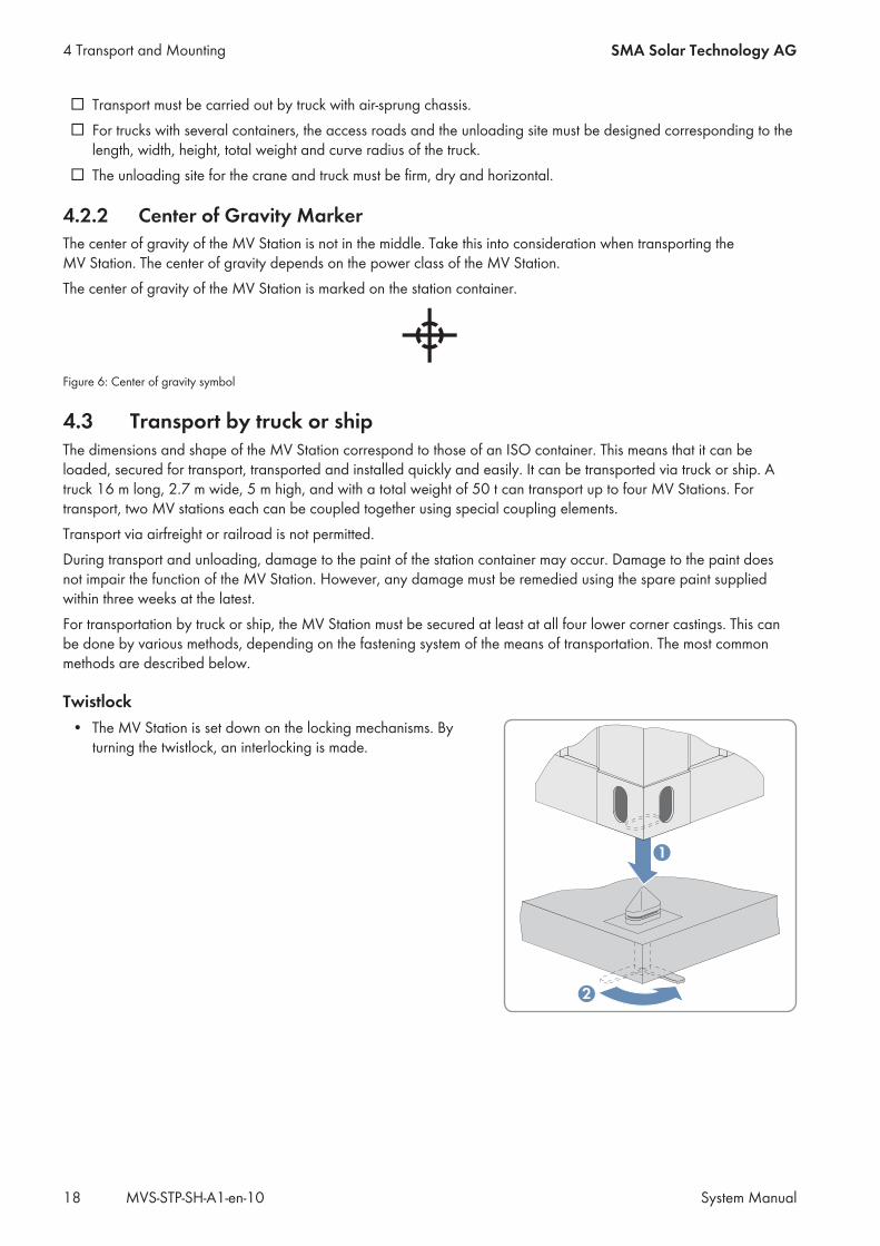
Twistlock• The MV Station is set down on the locking mechanisms. By
turning the twistlock, an interlocking is made.
4 Transport and Mounting SMA Solar Technology AG
System ManualMVS-STP-SH-A1-en-1018
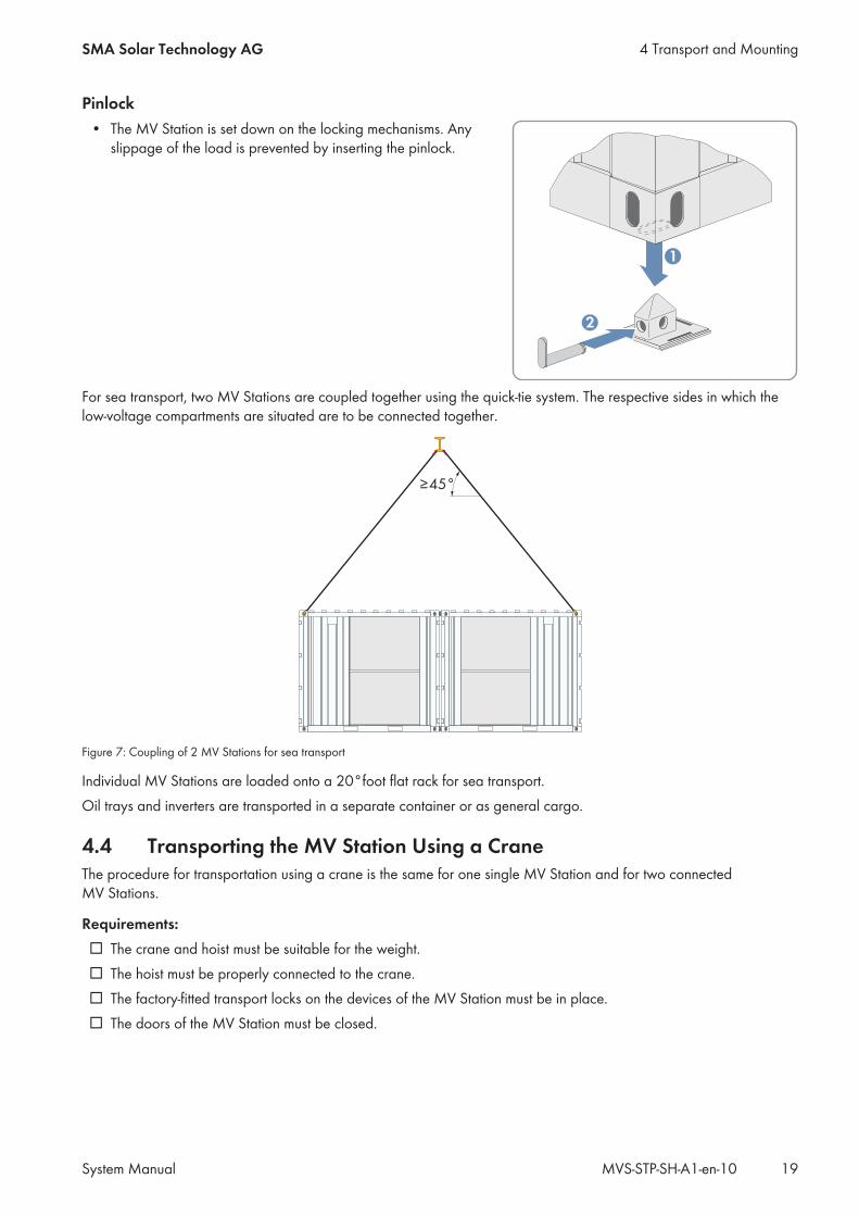
Pinlock• The MV Station is set down on the locking mechanisms. Any
slippage of the load is prevented by inserting the pinlock.
For sea transport, two MV Stations are coupled together using the quick-tie system. The respective sides in which thelow-voltage compartments are situated are to be connected together.
≥45°
Figure 7: Coupling of 2 MV Stations for sea transport
Individual MV Stations are loaded onto a 20°foot flat rack for sea transport.Oil trays and inverters are transported in a separate container or as general cargo.
4.4 Transporting the MV Station Using a CraneThe procedure for transportation using a crane is the same for one single MV Station and for two connectedMV Stations.
Requirements:☐ The crane and hoist must be suitable for the weight.☐ The hoist must be properly connected to the crane.☐ The factory-fitted transport locks on the devices of the MV Station must be in place.☐ The doors of the MV Station must be closed.
4 Transport and MountingSMA Solar Technology AG
System Manual 19MVS-STP-SH-A1-en-10
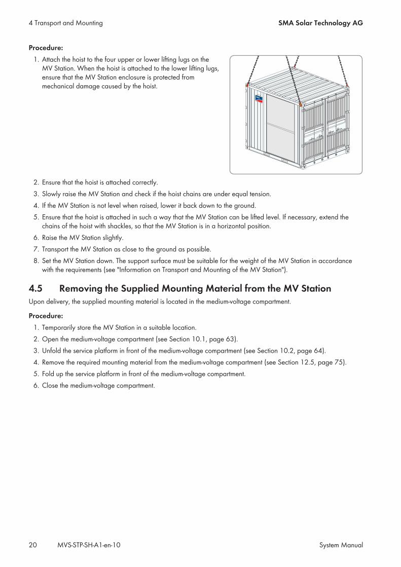
Procedure:1. Attach the hoist to the four upper or lower lifting lugs on the
MV Station. When the hoist is attached to the lower lifting lugs,ensure that the MV Station enclosure is protected frommechanical damage caused by the hoist.
2. Ensure that the hoist is attached correctly.3. Slowly raise the MV Station and check if the hoist chains are under equal tension.4. If the MV Station is not level when raised, lower it back down to the ground.5. Ensure that the hoist is attached in such a way that the MV Station can be lifted level. If necessary, extend the
chains of the hoist with shackles, so that the MV Station is in a horizontal position.6. Raise the MV Station slightly.7. Transport the MV Station as close to the ground as possible.8. Set the MV Station down. The support surface must be suitable for the weight of the MV Station in accordance
with the requirements (see "Information on Transport and Mounting of the MV Station").
4.5 Removing the Supplied Mounting Material from the MV StationUpon delivery, the supplied mounting material is located in the medium-voltage compartment.
Procedure:1. Temporarily store the MV Station in a suitable location.2. Open the medium-voltage compartment (see Section 10.1, page 63).3. Unfold the service platform in front of the medium-voltage compartment (see Section 10.2, page 64).4. Remove the required mounting material from the medium-voltage compartment (see Section 12.5, page 75).5. Fold up the service platform in front of the medium-voltage compartment.6. Close the medium-voltage compartment.
4 Transport and Mounting SMA Solar Technology AG
System ManualMVS-STP-SH-A1-en-1020
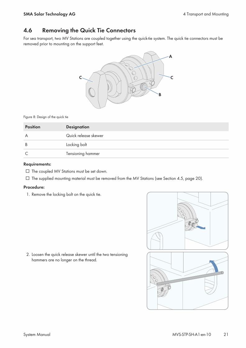
4.6 Removing the Quick Tie ConnectorsFor sea transport, two MV Stations are coupled together using the quick-tie system. The quick tie connectors must beremoved prior to mounting on the support feet.
A
CC
B
Figure 8: Design of the quick tie
Position Designation
A Quick release skewer
B Locking bolt
C Tensioning hammer
Requirements:☐ The coupled MV Stations must be set down.☐ The supplied mounting material must be removed from the MV Stations (see Section 4.5, page 20).
Procedure:1. Remove the locking bolt on the quick tie.
2. Loosen the quick release skewer until the two tensioninghammers are no longer on the thread.
4 Transport and MountingSMA Solar Technology AG
System Manual 21MVS-STP-SH-A1-en-10
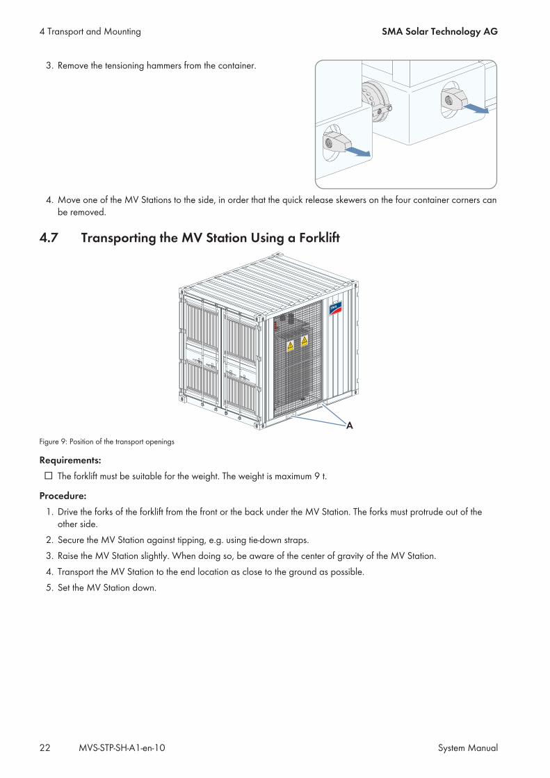
3. Remove the tensioning hammers from the container.
4. Move one of the MV Stations to the side, in order that the quick release skewers on the four container corners canbe removed.
4.7 Transporting the MV Station Using a Forklift
A
Figure 9: Position of the transport openings
Requirements:☐ The forklift must be suitable for the weight. The weight is maximum 9 t.
Procedure:1. Drive the forks of the forklift from the front or the back under the MV Station. The forks must protrude out of the
other side.2. Secure the MV Station against tipping, e.g. using tie-down straps.3. Raise the MV Station slightly. When doing so, be aware of the center of gravity of the MV Station.4. Transport the MV Station to the end location as close to the ground as possible.5. Set the MV Station down.
4 Transport and Mounting SMA Solar Technology AG
System ManualMVS-STP-SH-A1-en-1022
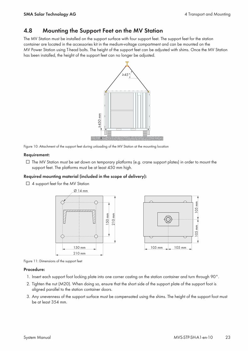
4.8 Mounting the Support Feet on the MV StationThe MV Station must be installed on the support surface with four support feet. The support feet for the stationcontainer are located in the accessories kit in the medium-voltage compartment and can be mounted on theMV Power Station using T-head bolts. The height of the support feet can be adjusted with shims. Once the MV Stationhas been installed, the height of the support feet can no longer be adjusted.
≥45°
≥4
50
mm
Figure 10: Attachment of the support feet during unloading of the MV Station at the mounting location
Requirement:☐ The MV Station must be set down on temporary platforms (e.g. crane support plates) in order to mount the
support feet. The platforms must be at least 450 mm high.
Required mounting material (included in the scope of delivery):☐ 4 support feet for the MV Station
Figure 11: Dimensions of the support feet
Procedure:1. Insert each support foot locking plate into one corner casting on the station container and turn through 90°.2. Tighten the nut (M20). When doing so, ensure that the short side of the support plate of the support foot is
aligned parallel to the station container doors.3. Any unevenness of the support surface must be compensated using the shims. The height of the support foot must
be at least 354 mm.
4 Transport and MountingSMA Solar Technology AG
System Manual 23MVS-STP-SH-A1-en-10
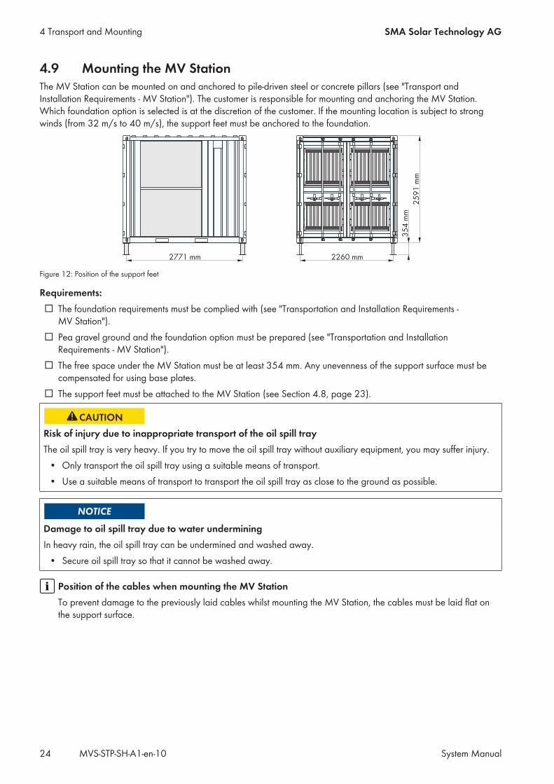
4.9 Mounting the MV StationThe MV Station can be mounted on and anchored to pile-driven steel or concrete pillars (see "Transport andInstallation Requirements - MV Station"). The customer is responsible for mounting and anchoring the MV Station.Which foundation option is selected is at the discretion of the customer. If the mounting location is subject to strongwinds (from 32 m/s to 40 m/s), the support feet must be anchored to the foundation.
2771 mm 2260 mm
25
91
mm
35
4 m
m
Figure 12: Position of the support feet
Requirements:☐ The foundation requirements must be complied with (see "Transportation and Installation Requirements -
MV Station").☐ Pea gravel ground and the foundation option must be prepared (see "Transportation and Installation
Requirements - MV Station").☐ The free space under the MV Station must be at least 354 mm. Any unevenness of the support surface must be
compensated for using base plates.☐ The support feet must be attached to the MV Station (see Section 4.8, page 23).
Risk of injury due to inappropriate transport of the oil spill trayThe oil spill tray is very heavy. If you try to move the oil spill tray without auxiliary equipment, you may suffer injury.
• Only transport the oil spill tray using a suitable means of transport.• Use a suitable means of transport to transport the oil spill tray as close to the ground as possible.
Damage to oil spill tray due to water underminingIn heavy rain, the oil spill tray can be undermined and washed away.
• Secure oil spill tray so that it cannot be washed away.
Position of the cables when mounting the MV StationTo prevent damage to the previously laid cables whilst mounting the MV Station, the cables must be laid flat onthe support surface.
4 Transport and Mounting SMA Solar Technology AG
System ManualMVS-STP-SH-A1-en-1024
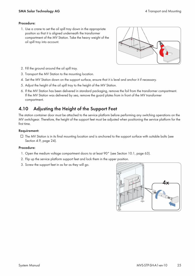
Procedure:1. Use a crane to set the oil spill tray down in the appropriate
position so that it is aligned underneath the transformercompartment of the MV Station. Take the heavy weight of theoil spill tray into account.
2. Fill the ground around the oil spill tray.3. Transport the MV Station to the mounting location.4. Set the MV Station down on the support surface, ensure that it is level and anchor it if necessary.5. Adjust the height of the oil spill tray to the height of the MV Station.6. If the MV Station has been delivered in standard packaging, remove the foil from the transformer compartment.
If the MV Station was delivered by sea, remove the guard plates from in front of the MV transformercompartment.
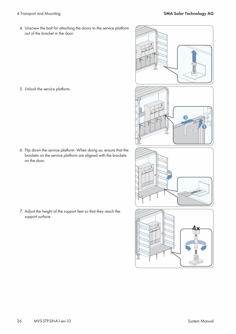
4.10 Adjusting the Height of the Support FeetThe station container door must be attached to the service platform before performing any switching operations on theMV switchgear. Therefore, the height of the support feet must be adjusted when positioning the service platform for thefirst time.
Requirement:☐ The MV Station is in its final mounting location and is anchored to the support surface with suitable bolts (see
Section 4.9, page 24).
Procedure:1. Open the medium voltage compartment doors to at least 90° (see Section 10.1, page 63).2. Flip up the service platform support feet and lock them in the upper position.3. Screw the support feet in as far as they will go.
4x4x
4 Transport and MountingSMA Solar Technology AG
System Manual 25MVS-STP-SH-A1-en-10
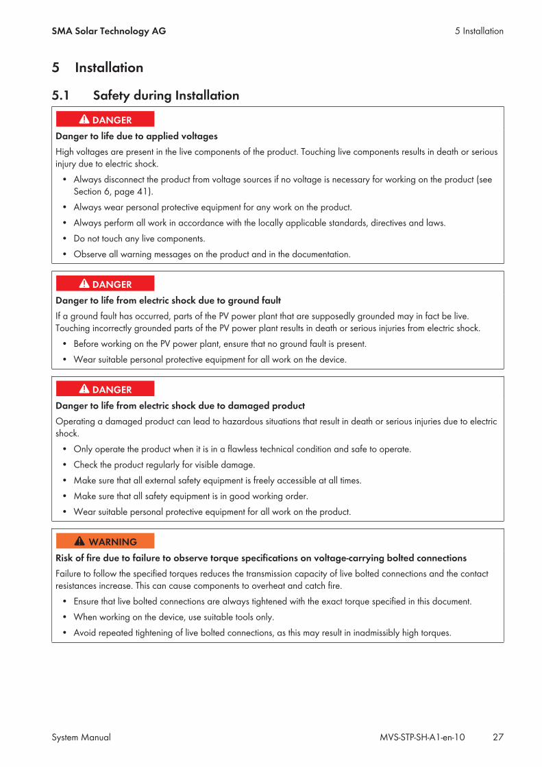
4. Unscrew the bolt for attaching the doors to the service platformout of the bracket in the door.
5. Unlock the service platform.
1
2
6. Flip down the service platform. When doing so, ensure that thebrackets on the service platform are aligned with the bracketson the door.
7. Adjust the height of the support feet so that they reach thesupport surface.
4x4x
4 Transport and Mounting SMA Solar Technology AG
System ManualMVS-STP-SH-A1-en-1026
5 Installation
5.1 Safety during Installation
Danger to life due to applied voltagesHigh voltages are present in the live components of the product. Touching live components results in death or seriousinjury due to electric shock.
• Always disconnect the product from voltage sources if no voltage is necessary for working on the product (seeSection 6, page 41).
• Always wear personal protective equipment for any work on the product.• Always perform all work in accordance with the locally applicable standards, directives and laws.• Do not touch any live components.• Observe all warning messages on the product and in the documentation.
Danger to life from electric shock due to ground faultIf a ground fault has occurred, parts of the PV power plant that are supposedly grounded may in fact be live.Touching incorrectly grounded parts of the PV power plant results in death or serious injuries from electric shock.
• Before working on the PV power plant, ensure that no ground fault is present.• Wear suitable personal protective equipment for all work on the device.
Danger to life from electric shock due to damaged productOperating a damaged product can lead to hazardous situations that result in death or serious injuries due to electricshock.
• Only operate the product when it is in a flawless technical condition and safe to operate.• Check the product regularly for visible damage.• Make sure that all external safety equipment is freely accessible at all times.• Make sure that all safety equipment is in good working order.• Wear suitable personal protective equipment for all work on the product.
Risk of fire due to failure to observe torque specifications on voltage-carrying bolted connectionsFailure to follow the specified torques reduces the transmission capacity of live bolted connections and the contactresistances increase. This can cause components to overheat and catch fire.
• Ensure that live bolted connections are always tightened with the exact torque specified in this document.• When working on the device, use suitable tools only.• Avoid repeated tightening of live bolted connections, as this may result in inadmissibly high torques.
5 InstallationSMA Solar Technology AG
System Manual 27MVS-STP-SH-A1-en-10
Damage to the devices due to sand, dust or moisture penetrationSand, dust or moisture penetration can damage the devices of the MV Station or impair their functionality.
• Do not open any devices during a sandstorm, precipitation or when humidity exceeds 95%.• Only perform maintenance work when the environment is dry and free of dust.• If the installation, maintenance or commissioning process is interrupted, mount all enclosure parts and close all
doors.
Damage to electronic components due to electrostatic dischargeElectrostatic discharge can damage or destroy electronic components.
• Observe the ESD safety regulations when working on the product.• Wear suitable personal protective equipment for all work on the product.• Discharge electrostatic charge by touching grounded enclosure parts or other grounded elements. Only then is
it safe to touch electronic components.
5.2 Installation SequenceThe sequence of installation work given in this section is recommended by SMA. It is important to begin the installationwith the preparatory work and the grounding connection. Therefore, SMA recommends that you adhere to thissequence to avoid problems during installation. Some of the installation work will only need to be carried out forcertain options.Observe the supplied circuit diagram during installation.
Task See
Removing the sealing plates in front of the MV transformer Section 5.3.1, page 29
Removing the transport locks Section 5.3.2, page 29
Removing the desiccant bags from the station container Section 5.3.3, page 30
Performing work on the low-voltage compartment Section 5.3.5, page 30
Performing work on the medium-voltage compartment Section 5.3.4, page 30
Connecting the grounding on the station container Section 5.4, page 31
Installing the low-voltage connection Section 5.5, page 33
Installing the medium-voltage connectionDepending on the order option, the medium-voltage connection will be installedon the MV switchgear or on the MV transformer
Section 5.6, page 35
Connecting the communication network* Section 5.7, page 38* optional
5 Installation SMA Solar Technology AG
System ManualMVS-STP-SH-A1-en-1028
5.3 Preparatory Work
5.3.1 Removing the Sealing Plates in front of the MV TransformerWith the "Sea Freight" order option, the grids in front of the MV transformer are covered with sealing plates.
Risk of injury when lifting the sealing plates or if they are droppedThere is risk of injury if the sealing plates are lifted incorrectly or dropped whilst the sealing plates are beingremoved. Weight of each sealing plate: 30 kg.
• 2 people are necessary for the removal of the sealing plates.• Carefully remove the sealing plates.
Procedure:• Remove the four sealing plates in front of the MV transformer one after another. The sealing plates will no longer
be needed and can be introduced into the recyclable material chain.
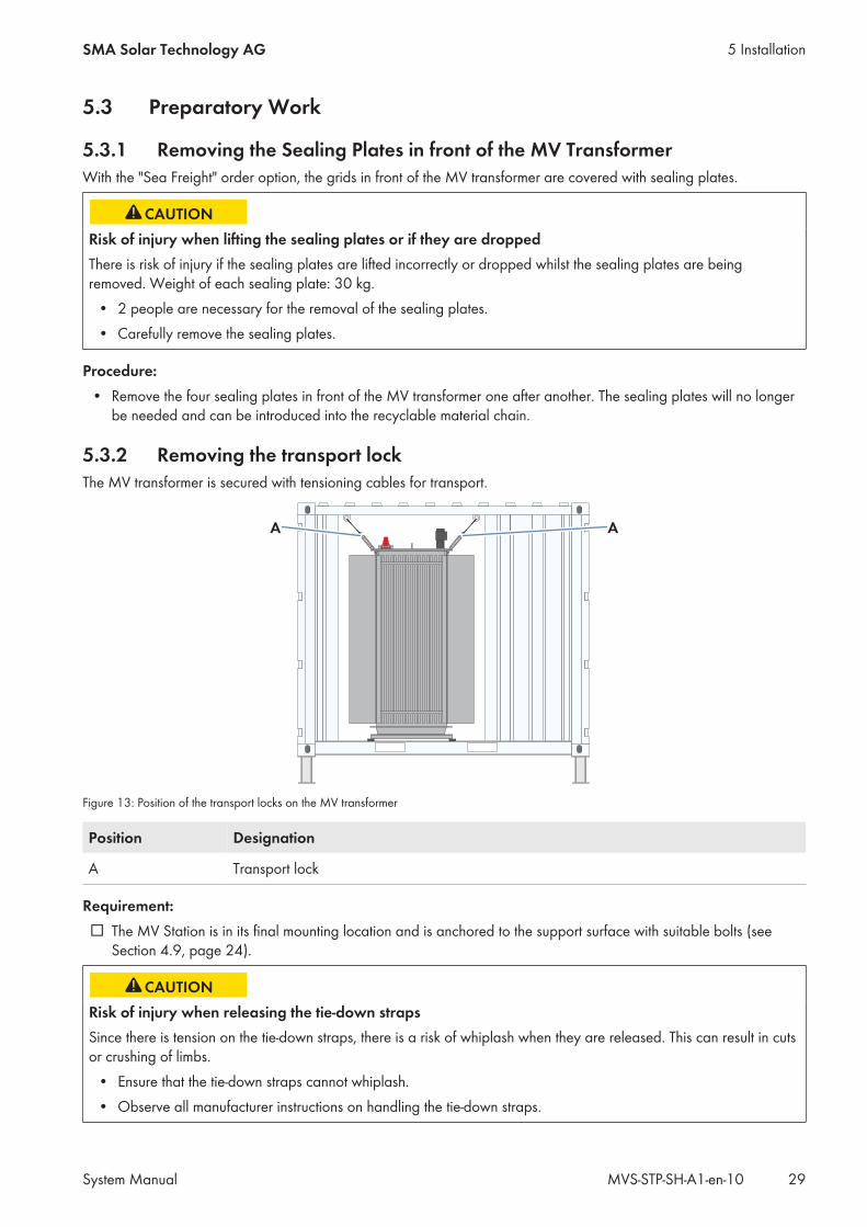
5.3.2 Removing the transport lockThe MV transformer is secured with tensioning cables for transport.
AA
Figure 13: Position of the transport locks on the MV transformer
Position Designation
A Transport lock
Requirement:☐ The MV Station is in its final mounting location and is anchored to the support surface with suitable bolts (see
Section 4.9, page 24).
Risk of injury when releasing the tie-down strapsSince there is tension on the tie-down straps, there is a risk of whiplash when they are released. This can result in cutsor crushing of limbs.
• Ensure that the tie-down straps cannot whiplash.• Observe all manufacturer instructions on handling the tie-down straps.
5 InstallationSMA Solar Technology AG
System Manual 29MVS-STP-SH-A1-en-10
Procedure:1. Remove the grids in front of the MV transformer (see Section 10.4, page 67).2. Remove the tensioning cables on the four corners of the MV transformer.3. Remount the grids in front of the MV transformer.4. Open the medium-voltage compartment (see Section 10.1, page 63).5. Set up the service platform of the medium-voltage switchgear (see Section 10.2, page 64).6. Release the tie-down straps on the MV switchgear.7. Fold up and lock the medium-voltage compartment service platform.8. Close the medium-voltage compartment.
5.3.3 Removing the Desiccant Bag from the Station ContainerDesiccant bags are included with sea freight orders. The desiccant bags absorb moisture formed during transport.
Procedure:1. Open the medium-voltage compartment (see Section 10.1, page 63).2. Remove the desiccant bags from the station container. Remove the cable ties around the desiccant bags using
diagonal cutting pliers. The desiccant bags are to be found at the following positions:• In the low-voltage compartment• In the compartment of the MV transformer• In the medium-voltage compartment
3. Close the medium-voltage compartment (see Section 10.1, page 63).
5.3.4 Working in the Medium-Voltage CompartmentWith the "Sea Freight" option, the cable entry for the medium voltage cable is covered with a base sheet for protectionduring transport.
Procedure:1. Open the medium-voltage compartment (see Section 10.1, page 63).2. Set up the service platform of the medium-voltage switchgear (see Section 10.2, page 64).3. If the MV Station was delivered via sea freight, mount the base plate for the cable entry:
• Disassemble the panels on the base of the MV switchgear (see Section 10.3, page 67).• Remove the bolts of the cover plate underneath the MV switchgear.• Remove the cover plate from the MV switchgear. The cover plate is no longer needed.• If a base plate for the cable entry was delivered, screw the base plate tightly over the opening for the cable
entry.• Mount the panels on the base of the MV switchgear.
4. Fold up and lock the medium-voltage compartment service platform.5. Close the medium-voltage compartment.
5.3.5 Working in the Low-Voltage CompartmentThe LV/HRC fuse in the fuse holders may have loosened during transport. A prerequisite for safe operation of theMV Station is that these are securely in position.With the "Sea Freight" order option, the ventilation grids in the door of the station container are protected with foilagainst moisture penetration.
5 Installation SMA Solar Technology AG
System ManualMVS-STP-SH-A1-en-1030
Procedure:1. Open the low-voltage compartment (see Section 10.1, page 63).2. Check that the LV/HRC fuses are securely positioned.3. Ensure that the contacts of the LV/HRC fuses and the fuse holders are free of corrosion.4. If the MV Station was delivered by sea, remove the foil from the ventilation grids in the doors.5. Close the low-voltage compartment.
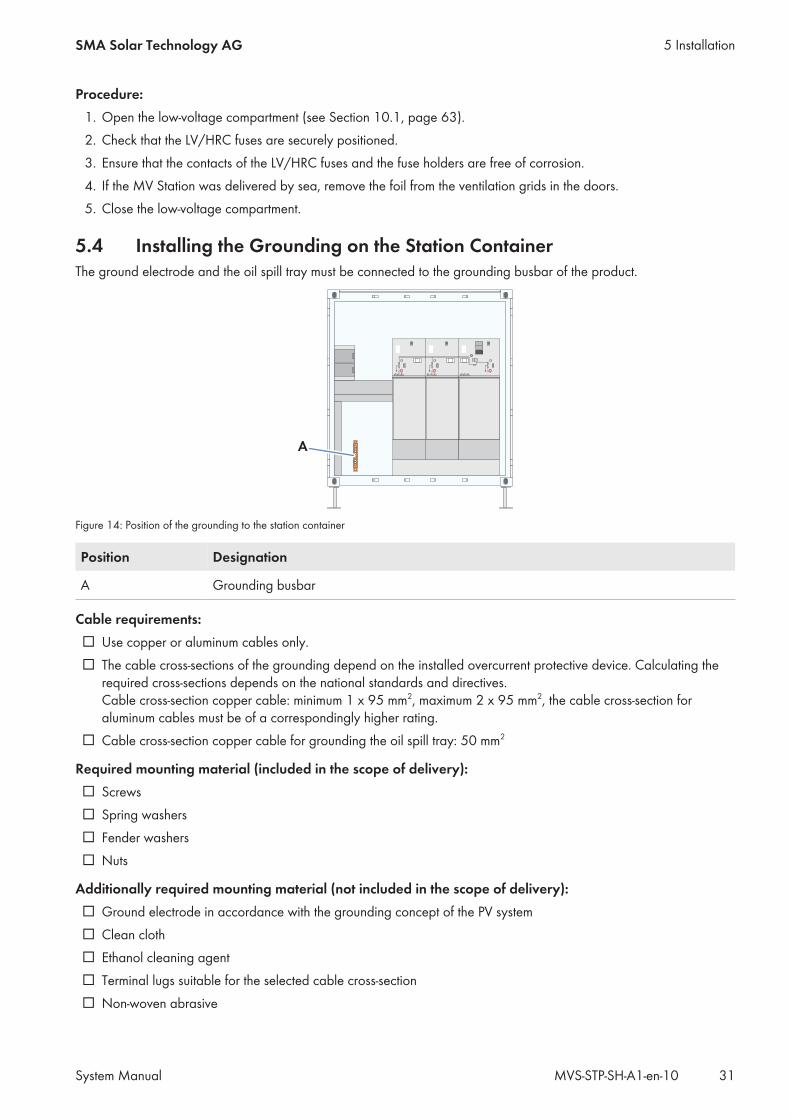
5.4 Installing the Grounding on the Station ContainerThe ground electrode and the oil spill tray must be connected to the grounding busbar of the product.
A
Figure 14: Position of the grounding to the station container
Position Designation
A Grounding busbar
Cable requirements:☐ Use copper or aluminum cables only.☐ The cable cross-sections of the grounding depend on the installed overcurrent protective device. Calculating the
required cross-sections depends on the national standards and directives.Cable cross-section copper cable: minimum 1 x 95 mm2, maximum 2 x 95 mm2, the cable cross-section foraluminum cables must be of a correspondingly higher rating.
☐ Cable cross-section copper cable for grounding the oil spill tray: 50 mm2
Required mounting material (included in the scope of delivery):☐ Screws☐ Spring washers☐ Fender washers☐ Nuts
Additionally required mounting material (not included in the scope of delivery):☐ Ground electrode in accordance with the grounding concept of the PV system☐ Clean cloth☐ Ethanol cleaning agent☐ Terminal lugs suitable for the selected cable cross-section☐ Non-woven abrasive
5 InstallationSMA Solar Technology AG
System Manual 31MVS-STP-SH-A1-en-10
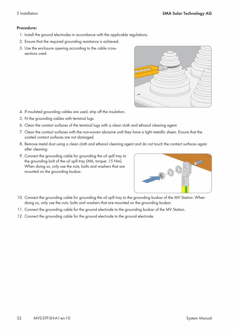
Procedure:1. Install the ground electrodes in accordance with the applicable regulations.2. Ensure that the required grounding resistance is achieved.3. Use the enclosure opening according to the cable cross-
sections used.
4. If insulated grounding cables are used, strip off the insulation.5. Fit the grounding cables with terminal lugs.6. Clean the contact surfaces of the terminal lugs with a clean cloth and ethanol cleaning agent.7. Clean the contact surfaces with the non-woven abrasive until they have a light metallic sheen. Ensure that the
coated contact surfaces are not damaged.8. Remove metal dust using a clean cloth and ethanol cleaning agent and do not touch the contact surfaces again
after cleaning.9. Connect the grounding cable for grounding the oil spill tray to
the grounding bolt of the oil spill tray (M6, torque: 15 Nm).When doing so, only use the nuts, bolts and washers that aremounted on the grounding busbar.
10. Connect the grounding cable for grounding the oil spill tray to the grounding busbar of the MV Station. Whendoing so, only use the nuts, bolts and washers that are mounted on the grounding busbar.
11. Connect the grounding cable for the ground electrode to the grounding busbar of the MV Station.12. Connect the grounding cable for the ground electrode to the ground electrode.
5 Installation SMA Solar Technology AG
System ManualMVS-STP-SH-A1-en-1032
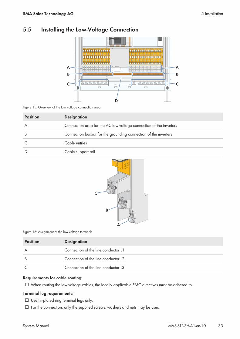
5.5 Installing the Low-Voltage Connection
A
B
C
A
B
C
D
Figure 15: Overview of the low voltage connection area
Position Designation
A Connection area for the AC low-voltage connection of the inverters
B Connection busbar for the grounding connection of the inverters
C Cable entries
D Cable support rail
C
B
A
Figure 16: Assignment of the low-voltage terminals
Position Designation
A Connection of the line conductor L1
B Connection of the line conductor L2
C Connection of the line conductor L3
Requirements for cable routing:☐ When routing the low-voltage cables, the locally applicable EMC directives must be adhered to.
Terminal lug requirements:☐ Use tin-plated ring terminal lugs only.☐ For the connection, only the supplied screws, washers and nuts may be used.
5 InstallationSMA Solar Technology AG
System Manual 33MVS-STP-SH-A1-en-10
☐ The terminal lugs must conform to the DIN 46235 specification.☐ Terminal lugs: M8
Cable requirements:☐ The cables must be rated for the maximum AC voltage.☐ A maximum of one inverter may be connected to each low-voltage connection.☐ A maximum of one cable may be connected to each connection bracket.☐ Use copper or aluminum cables only.☐ Cable cross-section: 16 mm2 to 95 mm2
☐ Temperature-resistant cables (90°C) must be used if ambient temperatures are higher than 40°C
Torques of the low voltage connections:
Type of terminal lug Torque
Tin-plated aluminum ring terminal lug 10 Nm
Tin-plated copper ring terminal lug 15 Nm
Additionally required mounting material (included in the scope of delivery):☐ Bolts, nuts and washers
Additionally required mounting material (not included in the scope of delivery):☐ Terminal lugs☐ Clean cloth☐ Ethanol cleaning agent☐ Non-woven abrasive
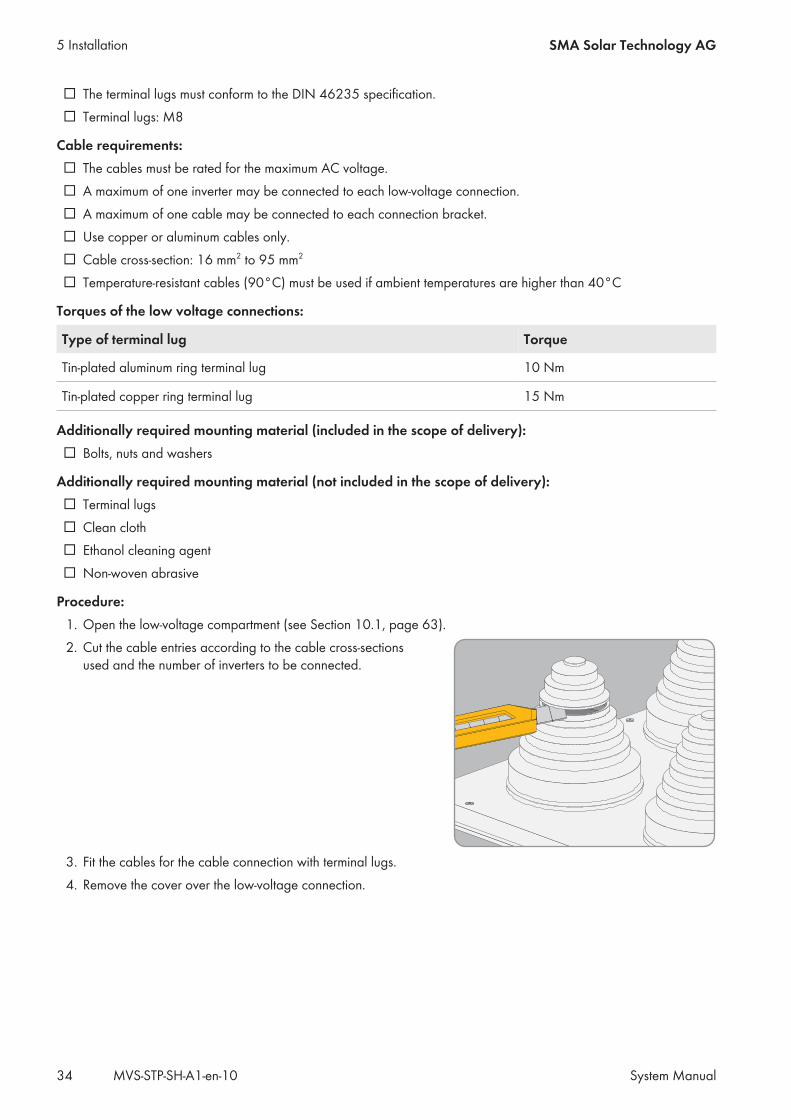
Procedure:1. Open the low-voltage compartment (see Section 10.1, page 63).2. Cut the cable entries according to the cable cross-sections
used and the number of inverters to be connected.
3. Fit the cables for the cable connection with terminal lugs.4. Remove the cover over the low-voltage connection.
5 Installation SMA Solar Technology AG
System ManualMVS-STP-SH-A1-en-1034
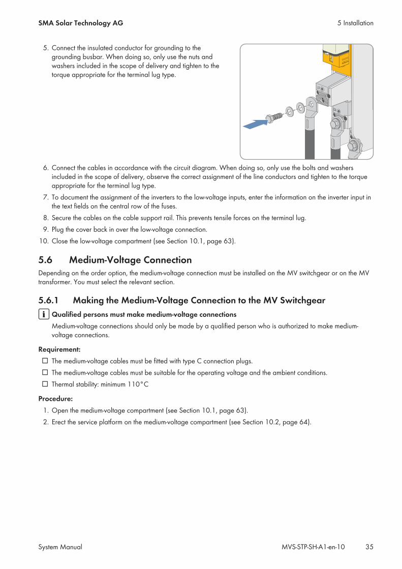
5. Connect the insulated conductor for grounding to thegrounding busbar. When doing so, only use the nuts andwashers included in the scope of delivery and tighten to thetorque appropriate for the terminal lug type.
6. Connect the cables in accordance with the circuit diagram. When doing so, only use the bolts and washersincluded in the scope of delivery, observe the correct assignment of the line conductors and tighten to the torqueappropriate for the terminal lug type.
7. To document the assignment of the inverters to the low-voltage inputs, enter the information on the inverter input inthe text fields on the central row of the fuses.
8. Secure the cables on the cable support rail. This prevents tensile forces on the terminal lug.9. Plug the cover back in over the low-voltage connection.
10. Close the low-voltage compartment (see Section 10.1, page 63).
5.6 Medium-Voltage ConnectionDepending on the order option, the medium-voltage connection must be installed on the MV switchgear or on the MVtransformer. You must select the relevant section.
5.6.1 Making the Medium-Voltage Connection to the MV SwitchgearQualified persons must make medium-voltage connectionsMedium-voltage connections should only be made by a qualified person who is authorized to make medium-voltage connections.
Requirement:☐ The medium-voltage cables must be fitted with type C connection plugs.☐ The medium-voltage cables must be suitable for the operating voltage and the ambient conditions.☐ Thermal stability: minimum 110°C
Procedure:1. Open the medium-voltage compartment (see Section 10.1, page 63).2. Erect the service platform on the medium-voltage compartment (see Section 10.2, page 64).
5 InstallationSMA Solar Technology AG
System Manual 35MVS-STP-SH-A1-en-10
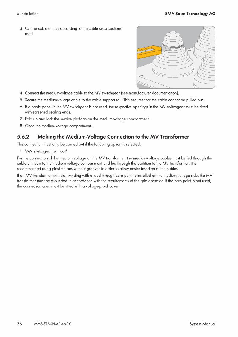
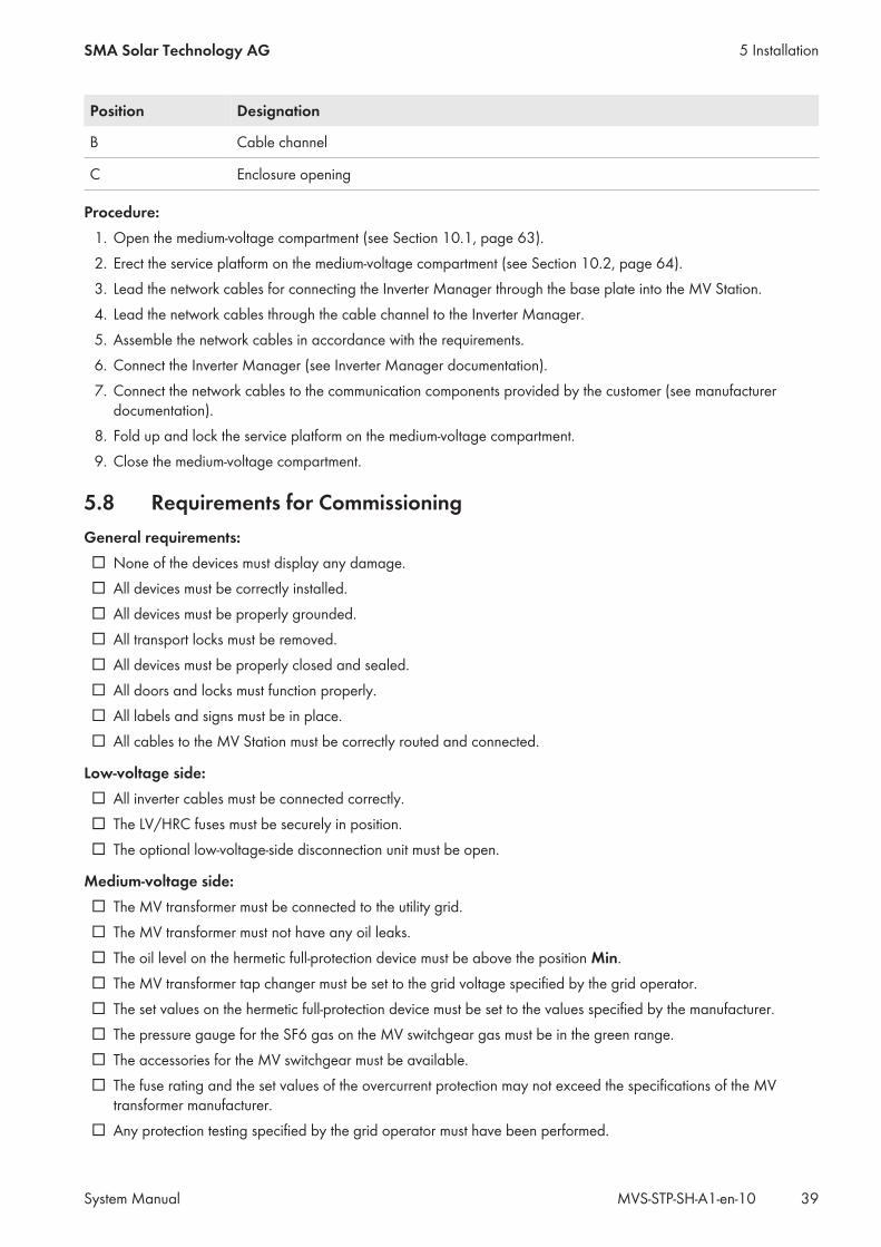
3. Cut the cable entries according to the cable cross-sectionsused.
4. Connect the medium-voltage cable to the MV switchgear (see manufacturer documentation).5. Secure the medium-voltage cable to the cable support rail. This ensures that the cable cannot be pulled out.6. If a cable panel in the MV switchgear is not used, the respective openings in the MV switchgear must be fitted
with screened sealing ends.7. Fold up and lock the service platform on the medium-voltage compartment.8. Close the medium-voltage compartment.
5.6.2 Making the Medium-Voltage Connection to the MV TransformerThis connection must only be carried out if the following option is selected:
• "MV switchgear: without"For the connection of the medium voltage on the MV transformer, the medium-voltage cables must be fed through thecable entries into the medium voltage compartment and led through the partition to the MV transformer. It isrecommended using plastic tubes without grooves in order to allow easier insertion of the cables.If an MV transformer with star winding with a lead-through zero point is installed on the medium-voltage side, the MVtransformer must be grounded in accordance with the requirements of the grid operator. If the zero point is not used,the connection area must be fitted with a voltage-proof cover.
5 Installation SMA Solar Technology AG
System ManualMVS-STP-SH-A1-en-1036
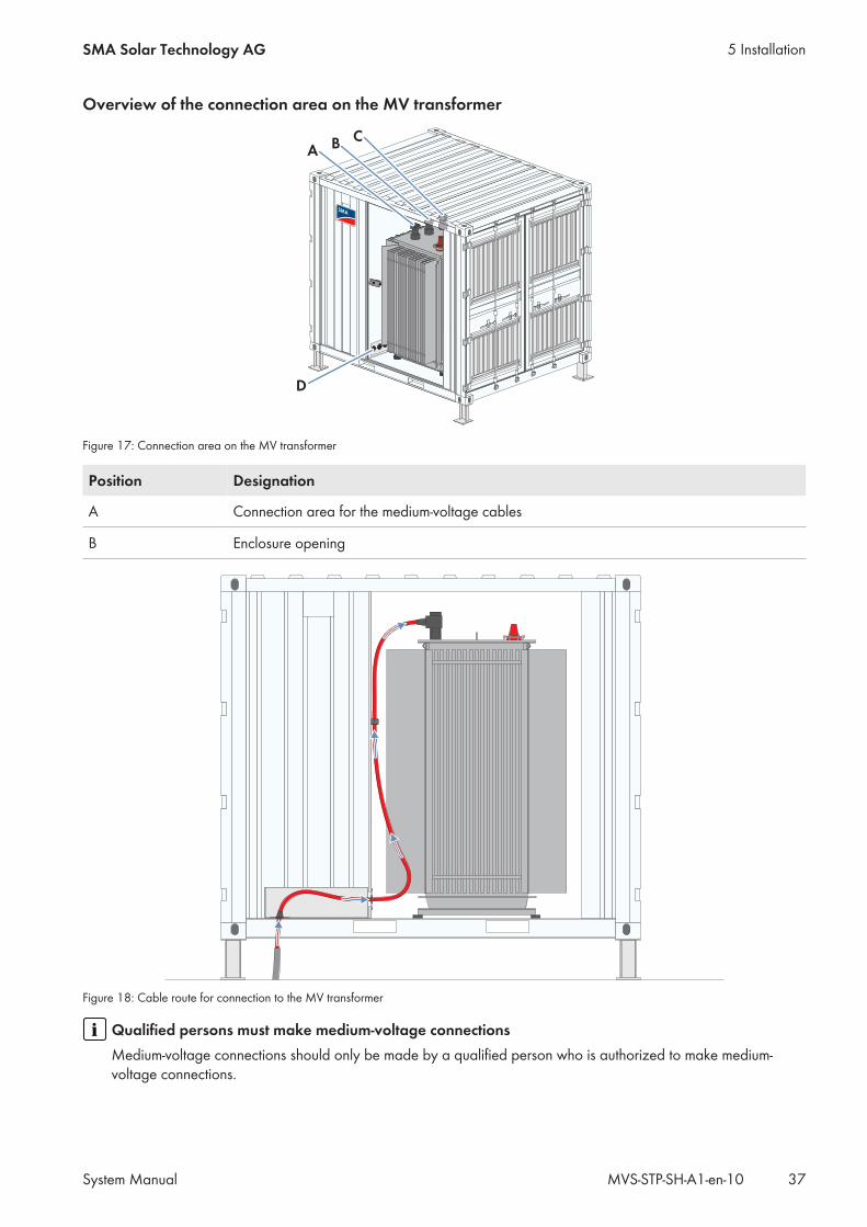
Overview of the connection area on the MV transformer
A
D
BC
Figure 17: Connection area on the MV transformer
Position Designation
A Connection area for the medium-voltage cables
B Enclosure opening
Figure 18: Cable route for connection to the MV transformer
Qualified persons must make medium-voltage connectionsMedium-voltage connections should only be made by a qualified person who is authorized to make medium-voltage connections.
5 InstallationSMA Solar Technology AG
System Manual 37MVS-STP-SH-A1-en-10
Requirement:☐ The medium-voltage cables must be fitted with type C connection plugs.
Procedure:1. Open the medium-voltage compartment (see Section 10.1, page 63).2. Erect the service platform on the medium-voltage compartment (see Section 10.2, page 64).3. Cut the cable entries according to the cable cross-sections
used.
4. Remove the grids in front of the MV transformer.5. Lead the medium-voltage cables through the partition to the MV transformer.6. Connect the medium-voltage cables to the MV transformer (see manufacturer documentation).7. Secure the medium-voltage cables to the strain relief in the transformer compartment. This ensures that the cable
cannot be pulled out.8. Remount the grids in front of the MV transformer.9. Fold up and lock the service platform on the medium-voltage compartment.
10. Close the medium-voltage compartment.
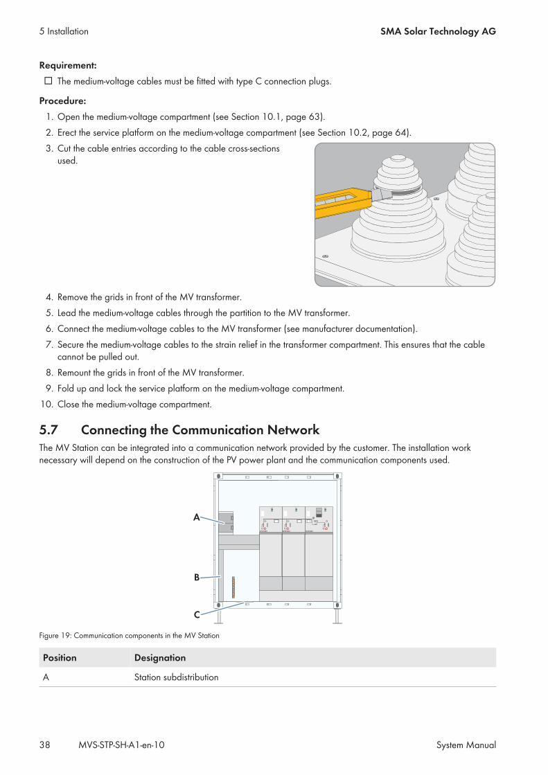
5.7 Connecting the Communication NetworkThe MV Station can be integrated into a communication network provided by the customer. The installation worknecessary will depend on the construction of the PV power plant and the communication components used.
B
A
C
Figure 19: Communication components in the MV Station
Position Designation
A Station subdistribution
5 Installation SMA Solar Technology AG
System ManualMVS-STP-SH-A1-en-1038
Position Designation
B Cable channel
C Enclosure opening
Procedure:1. Open the medium-voltage compartment (see Section 10.1, page 63).2. Erect the service platform on the medium-voltage compartment (see Section 10.2, page 64).3. Lead the network cables for connecting the Inverter Manager through the base plate into the MV Station.4. Lead the network cables through the cable channel to the Inverter Manager.5. Assemble the network cables in accordance with the requirements.6. Connect the Inverter Manager (see Inverter Manager documentation).7. Connect the network cables to the communication components provided by the customer (see manufacturer
documentation).8. Fold up and lock the service platform on the medium-voltage compartment.9. Close the medium-voltage compartment.
5.8 Requirements for CommissioningGeneral requirements:☐ None of the devices must display any damage.☐ All devices must be correctly installed.☐ All devices must be properly grounded.☐ All transport locks must be removed.☐ All devices must be properly closed and sealed.☐ All doors and locks must function properly.☐ All labels and signs must be in place.☐ All cables to the MV Station must be correctly routed and connected.
Low-voltage side:☐ All inverter cables must be connected correctly.☐ The LV/HRC fuses must be securely in position.☐ The optional low-voltage-side disconnection unit must be open.
Medium-voltage side:☐ The MV transformer must be connected to the utility grid.☐ The MV transformer must not have any oil leaks.☐ The oil level on the hermetic full-protection device must be above the position Min.☐ The MV transformer tap changer must be set to the grid voltage specified by the grid operator.☐ The set values on the hermetic full-protection device must be set to the values specified by the manufacturer.☐ The pressure gauge for the SF6 gas on the MV switchgear gas must be in the green range.☐ The accessories for the MV switchgear must be available.☐ The fuse rating and the set values of the overcurrent protection may not exceed the specifications of the MV
transformer manufacturer.☐ Any protection testing specified by the grid operator must have been performed.
5 InstallationSMA Solar Technology AG
System Manual 39MVS-STP-SH-A1-en-10
☐ The grids in front of the MV transformer must be mounted.☐ All unused cable entries must be closed off.
MV Station:☐ The desiccant bags must be removed from the MV Station.
Documentation:☐ All documentation must be available.☐ SMA Solar Technology AG must have access to the safety documentation for the construction site.☐ All system documentation such as cabling diagrams must be present.
5 Installation SMA Solar Technology AG
System ManualMVS-STP-SH-A1-en-1040
6 Disconnecting and Reconnecting
6.1 Safety When Disconnecting and Reconnecting Voltage Sources
Danger to life due to applied voltagesHigh voltages are present in the live components of the product. Touching live components results in death or seriousinjury due to electric shock.
• Always disconnect the product from voltage sources if no voltage is necessary for working on the product (seeSection 6, page 41).
• Always wear personal protective equipment for any work on the product.• Always perform all work in accordance with the locally applicable standards, directives and laws.• Do not touch any live components.• Observe all warning messages on the product and in the documentation.
Danger to life due to electric arcs if measuring device is not connected correctlyIf the measurement points are incorrectly contacted, this can cause an electric arc. Electric arcs can result in death orserious injury.
• Select the appropriate measurement range on the measuring device.• Wear suitable personal protective equipment for all work on the device.• Select correct measurement points.
Danger to life due to arc fault in the event of faults in the MV switchgearIf there is a fault in the MV switchgear, arc faults may occur during operation of the product which can result indeath or serious injuries. If arc faults occur in the MV switchgear, the pressure escapes downwards below themedium-voltage compartment.
• Only perform work on the MV switchgear when it is in a voltage-free state.• Prior to commissioning and operating the MV switchgear, close the front panels of the base below the MV
switchgear.• Open the medium-voltage compartment doors to the 90° position and attach to the folded out platform before
performing switching operations.• Only perform switching operations on the MV switchgear from the service platform.• When switching operations are performed, all persons that are not on the service platform have to keep a safe
distance from the product.• All work and switching operations on the MV switchgear may only be performed by qualified persons wearing
adequate personal protective equipment.
6 Disconnecting and ReconnectingSMA Solar Technology AG
System Manual 41MVS-STP-SH-A1-en-10
Risk of burns due to hot componentsSome components of the product can get very hot during operation. Touching these components can cause burns.
• Observe the warnings on all components.• During operation, do not touch any components marked with such warnings.• After switching off the product, wait until any hot components have cooled down sufficiently.• Wear suitable personal protective equipment for all work on the product.
Connecting and disconnecting medium voltageOnly a duly authorized person trained in electrical safety is allowed to connect and disconnect the mediumvoltage.
6.2 Disconnecting the MV Station From Voltage SourcesConnecting and disconnecting medium voltageOnly a duly authorized person trained in electrical safety is allowed to connect and disconnect the mediumvoltage.
Requirement:☐ Ensure that the inverters are disconnected from all voltage sources.
Procedure:1. Open the low-voltage compartment (see Section 10.1, page 63).2. If a low-voltage disconnection unit has been installed, open the low-voltage disconnection unit.3. If the MV Station is equipped with an MV switchgear, open the medium-voltage compartment of the MV Station
and erect the service platform on the medium-voltage compartment (see Section 10.2, page 64). When doingso, ensure that the columns on the service platform are closed.
4. Switch off the MV switchgear transformer panel, ensure that this is voltage-free and ground the outlet by insertingthe ground electrode.
5. Switch off and ground the MV switchgear ring circuits.6. Ensure that the ring-circuit power cables are voltage-free.7. Ground the upstream MV switchgear.8. If the MV Station is not equipped with an MV switchgear, disconnect the MV Station from the utility grid at the
superordinate MV switchgear (see manufacturer documentation). Always observe the five safety rules.
6.3 Reconnecting the MV StationConnecting and disconnecting medium voltageOnly a duly authorized person trained in electrical safety is allowed to connect and disconnect the mediumvoltage.
Procedure:1. Remove the MV Station grounding.2. Connect the MV Station to the superordinate MV switchgear (see manufacturer documentation).3. Where necessary, connect the outlet to the next MV switchgear. When doing so, ensure that the local conditions
are observed and that the grounding has been removed from the downstream cable panel.4. If the MV Station is equipped with an MV switchgear, open the medium-voltage compartment of the MV Station
and erect the service platform on the medium-voltage compartment (see Section 10.2, page 64).
6 Disconnecting and Reconnecting SMA Solar Technology AG
System ManualMVS-STP-SH-A1-en-1042
5. Remove the MV switchgear grounding and switch on the MV switchgear ring circuit.6. Remove the grounding on the MV switchgear transformer outlet.7. Connect the MV transformer.8. Open the low-voltage compartment.9. Close the low-voltage disconnection unit.
10. Fold up and lock the service platform on the medium-voltage compartment.11. Close the MV Station doors (see Section 10.1, page 63).
6 Disconnecting and ReconnectingSMA Solar Technology AG
System Manual 43MVS-STP-SH-A1-en-10
7 Troubleshooting
7.1 Safety during Troubleshooting
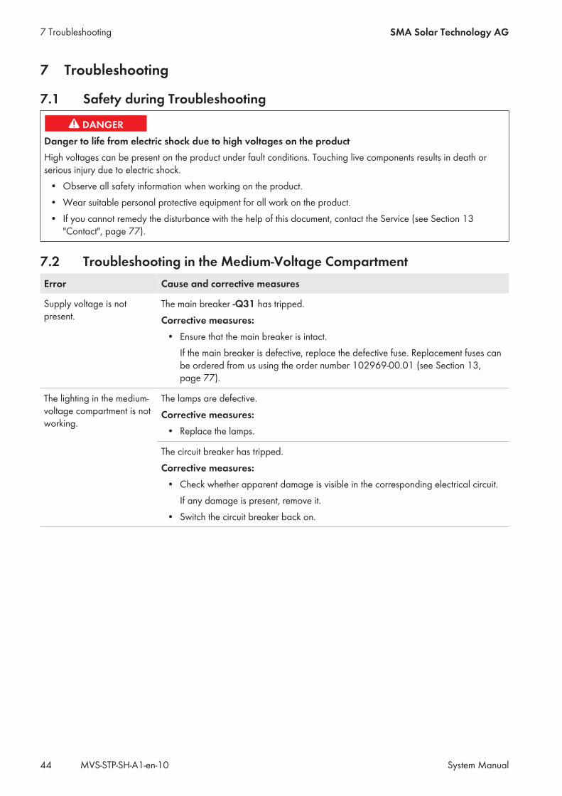
Danger to life from electric shock due to high voltages on the productHigh voltages can be present on the product under fault conditions. Touching live components results in death orserious injury due to electric shock.
• Observe all safety information when working on the product.• Wear suitable personal protective equipment for all work on the product.• If you cannot remedy the disturbance with the help of this document, contact the Service (see Section 13
"Contact", page 77).
7.2 Troubleshooting in the Medium-Voltage CompartmentError Cause and corrective measures
Supply voltage is notpresent.
The main breaker -Q31 has tripped.Corrective measures:
• Ensure that the main breaker is intact.If the main breaker is defective, replace the defective fuse. Replacement fuses canbe ordered from us using the order number 102969-00.01 (see Section 13,page 77).
The lighting in the medium-voltage compartment is notworking.
The lamps are defective.Corrective measures:
• Replace the lamps.
The circuit breaker has tripped.Corrective measures:
• Check whether apparent damage is visible in the corresponding electrical circuit.If any damage is present, remove it.
• Switch the circuit breaker back on.
7 Troubleshooting SMA Solar Technology AG
System ManualMVS-STP-SH-A1-en-1044
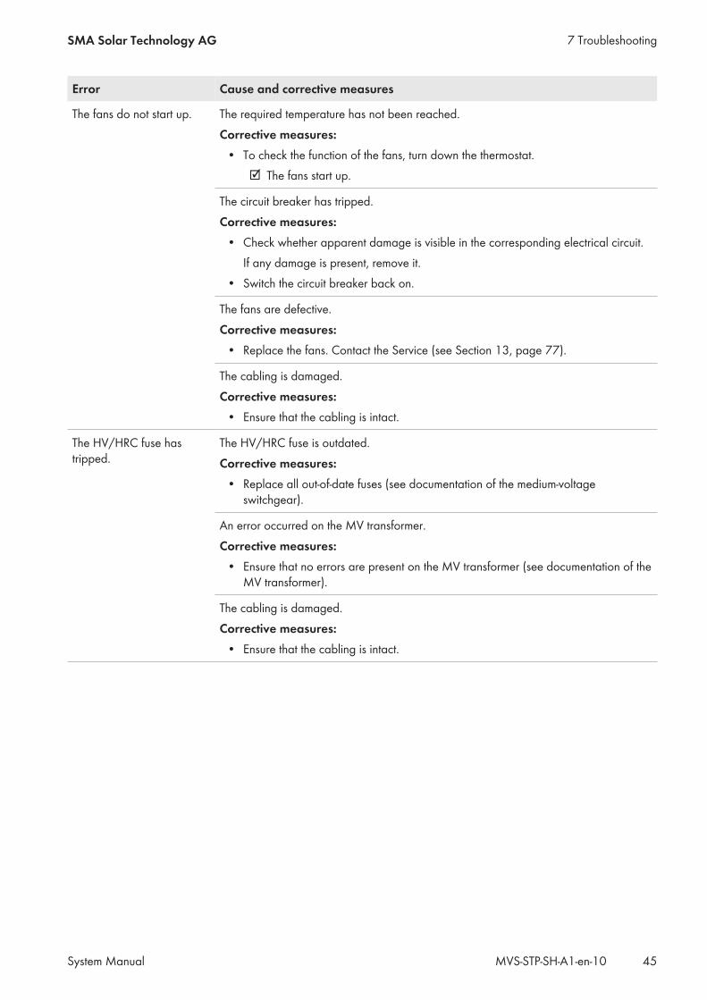
Error Cause and corrective measures
The fans do not start up. The required temperature has not been reached.Corrective measures:
• To check the function of the fans, turn down the thermostat.☑ The fans start up.
The circuit breaker has tripped.Corrective measures:
• Check whether apparent damage is visible in the corresponding electrical circuit.If any damage is present, remove it.
• Switch the circuit breaker back on.
The fans are defective.Corrective measures:
• Replace the fans. Contact the Service (see Section 13, page 77).
The cabling is damaged.Corrective measures:
• Ensure that the cabling is intact.
The HV/HRC fuse hastripped.
The HV/HRC fuse is outdated.Corrective measures:
• Replace all out-of-date fuses (see documentation of the medium-voltageswitchgear).
An error occurred on the MV transformer.Corrective measures:
• Ensure that no errors are present on the MV transformer (see documentation of theMV transformer).
The cabling is damaged.Corrective measures:
• Ensure that the cabling is intact.
7 TroubleshootingSMA Solar Technology AG
System Manual 45MVS-STP-SH-A1-en-10
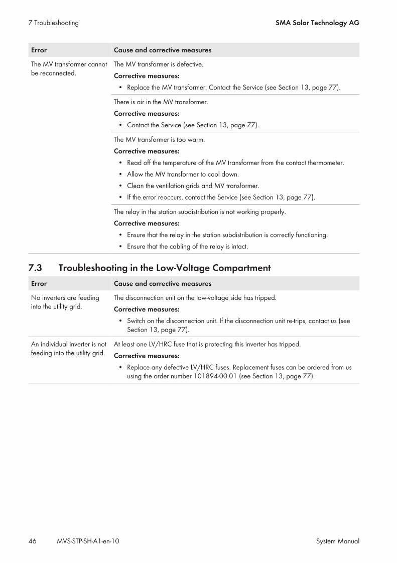
Error Cause and corrective measures
The MV transformer cannotbe reconnected.
The MV transformer is defective.Corrective measures:
• Replace the MV transformer. Contact the Service (see Section 13, page 77).
There is air in the MV transformer.Corrective measures:
• Contact the Service (see Section 13, page 77).
The MV transformer is too warm.Corrective measures:
• Read off the temperature of the MV transformer from the contact thermometer.• Allow the MV transformer to cool down.• Clean the ventilation grids and MV transformer.• If the error reoccurs, contact the Service (see Section 13, page 77).
The relay in the station subdistribution is not working properly.Corrective measures:
• Ensure that the relay in the station subdistribution is correctly functioning.• Ensure that the cabling of the relay is intact.
7.3 Troubleshooting in the Low-Voltage CompartmentError Cause and corrective measures
No inverters are feedinginto the utility grid.
The disconnection unit on the low-voltage side has tripped.Corrective measures:
• Switch on the disconnection unit. If the disconnection unit re-trips, contact us (seeSection 13, page 77).
An individual inverter is notfeeding into the utility grid.
At least one LV/HRC fuse that is protecting this inverter has tripped.Corrective measures:
• Replace any defective LV/HRC fuses. Replacement fuses can be ordered from ususing the order number 101894-00.01 (see Section 13, page 77).
7 Troubleshooting SMA Solar Technology AG
System ManualMVS-STP-SH-A1-en-1046
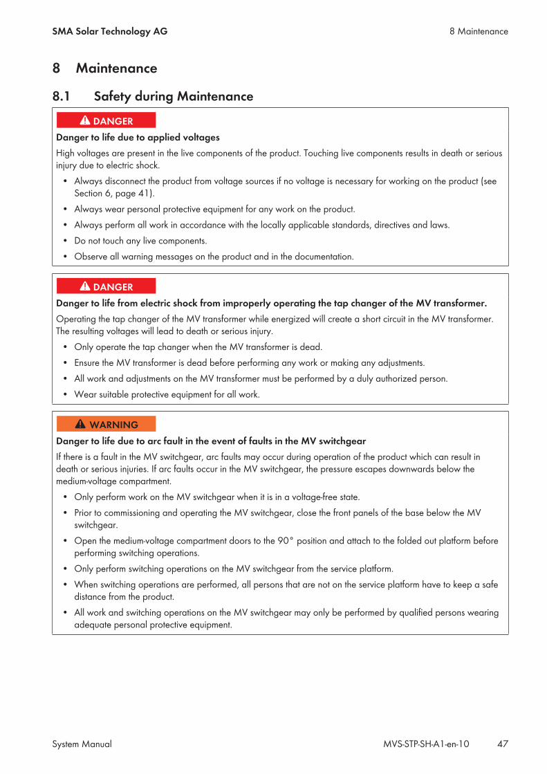
8 Maintenance
8.1 Safety during Maintenance
Danger to life due to applied voltagesHigh voltages are present in the live components of the product. Touching live components results in death or seriousinjury due to electric shock.
• Always disconnect the product from voltage sources if no voltage is necessary for working on the product (seeSection 6, page 41).
• Always wear personal protective equipment for any work on the product.• Always perform all work in accordance with the locally applicable standards, directives and laws.• Do not touch any live components.• Observe all warning messages on the product and in the documentation.
Danger to life from electric shock from improperly operating the tap changer of the MV transformer.Operating the tap changer of the MV transformer while energized will create a short circuit in the MV transformer.The resulting voltages will lead to death or serious injury.
• Only operate the tap changer when the MV transformer is dead.• Ensure the MV transformer is dead before performing any work or making any adjustments.• All work and adjustments on the MV transformer must be performed by a duly authorized person.• Wear suitable protective equipment for all work.
Danger to life due to arc fault in the event of faults in the MV switchgearIf there is a fault in the MV switchgear, arc faults may occur during operation of the product which can result indeath or serious injuries. If arc faults occur in the MV switchgear, the pressure escapes downwards below themedium-voltage compartment.
• Only perform work on the MV switchgear when it is in a voltage-free state.• Prior to commissioning and operating the MV switchgear, close the front panels of the base below the MV
switchgear.• Open the medium-voltage compartment doors to the 90° position and attach to the folded out platform before
performing switching operations.• Only perform switching operations on the MV switchgear from the service platform.• When switching operations are performed, all persons that are not on the service platform have to keep a safe
distance from the product.• All work and switching operations on the MV switchgear may only be performed by qualified persons wearing
adequate personal protective equipment.
8 MaintenanceSMA Solar Technology AG
System Manual 47MVS-STP-SH-A1-en-10
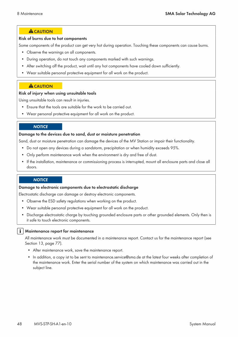
Risk of burns due to hot componentsSome components of the product can get very hot during operation. Touching these components can cause burns.
• Observe the warnings on all components.• During operation, do not touch any components marked with such warnings.• After switching off the product, wait until any hot components have cooled down sufficiently.• Wear suitable personal protective equipment for all work on the product.
Risk of injury when using unsuitable toolsUsing unsuitable tools can result in injuries.
• Ensure that the tools are suitable for the work to be carried out.• Wear personal protective equipment for all work on the product.
Damage to the devices due to sand, dust or moisture penetrationSand, dust or moisture penetration can damage the devices of the MV Station or impair their functionality.
• Do not open any devices during a sandstorm, precipitation or when humidity exceeds 95%.• Only perform maintenance work when the environment is dry and free of dust.• If the installation, maintenance or commissioning process is interrupted, mount all enclosure parts and close all
doors.
Damage to electronic components due to electrostatic dischargeElectrostatic discharge can damage or destroy electronic components.
• Observe the ESD safety regulations when working on the product.• Wear suitable personal protective equipment for all work on the product.• Discharge electrostatic charge by touching grounded enclosure parts or other grounded elements. Only then is
it safe to touch electronic components.
Maintenance report for maintenanceAll maintenance work must be documented in a maintenance report. Contact us for the maintenance report (seeSection 13, page 77).
• After maintenance work, save the maintenance report.• In addition, a copy ist to be sent to [email protected] at the latest four weeks after completion of
the maintenance work. Enter the serial number of the system on which maintenance was carried out in thesubject line.
8 Maintenance SMA Solar Technology AG
System ManualMVS-STP-SH-A1-en-1048
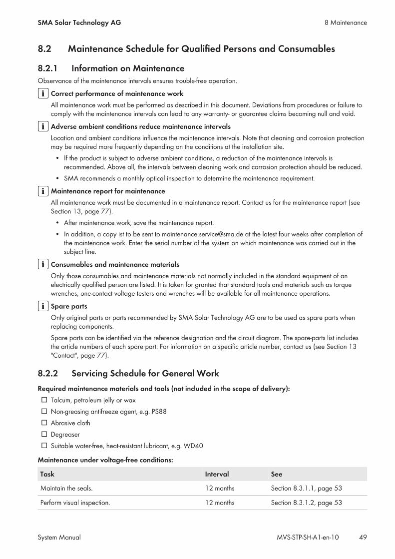
8.2 Maintenance Schedule for Qualified Persons and Consumables
8.2.1 Information on MaintenanceObservance of the maintenance intervals ensures trouble-free operation.
Correct performance of maintenance workAll maintenance work must be performed as described in this document. Deviations from procedures or failure tocomply with the maintenance intervals can lead to any warranty- or guarantee claims becoming null and void.
Adverse ambient conditions reduce maintenance intervalsLocation and ambient conditions influence the maintenance intervals. Note that cleaning and corrosion protectionmay be required more frequently depending on the conditions at the installation site.
• If the product is subject to adverse ambient conditions, a reduction of the maintenance intervals isrecommended. Above all, the intervals between cleaning work and corrosion protection should be reduced.
• SMA recommends a monthly optical inspection to determine the maintenance requirement.
Maintenance report for maintenanceAll maintenance work must be documented in a maintenance report. Contact us for the maintenance report (seeSection 13, page 77).
• After maintenance work, save the maintenance report.• In addition, a copy ist to be sent to [email protected] at the latest four weeks after completion of
the maintenance work. Enter the serial number of the system on which maintenance was carried out in thesubject line.
Consumables and maintenance materialsOnly those consumables and maintenance materials not normally included in the standard equipment of anelectrically qualified person are listed. It is taken for granted that standard tools and materials such as torquewrenches, one-contact voltage testers and wrenches will be available for all maintenance operations.
Spare partsOnly original parts or parts recommended by SMA Solar Technology AG are to be used as spare parts whenreplacing components.Spare parts can be identified via the reference designation and the circuit diagram. The spare-parts list includesthe article numbers of each spare part. For information on a specific article number, contact us (see Section 13"Contact", page 77).
8.2.2 Servicing Schedule for General WorkRequired maintenance materials and tools (not included in the scope of delivery):☐ Talcum, petroleum jelly or wax☐ Non-greasing antifreeze agent, e.g. PS88☐ Abrasive cloth☐ Degreaser☐ Suitable water-free, heat-resistant lubricant, e.g. WD40
Maintenance under voltage-free conditions:
Task Interval See
Maintain the seals. 12 months Section 8.3.1.1, page 53
Perform visual inspection. 12 months Section 8.3.1.2, page 53
8 MaintenanceSMA Solar Technology AG
System Manual 49MVS-STP-SH-A1-en-10
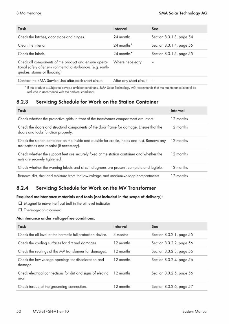
Task Interval See
Check the latches, door stops and hinges. 24 months Section 8.3.1.3, page 54
Clean the interior. 24 months* Section 8.3.1.4, page 55
Check the labels. 24 months* Section 8.3.1.5, page 55
Check all components of the product and ensure opera-tional safety after environmental disturbances (e.g. earth-quakes, storms or flooding).
Where necessary ‒
Contact the SMA Service Line after each short circuit. After any short circuit ‒* If the product is subject to adverse ambient conditions, SMA Solar Technology AG recommends that the maintenance interval be
reduced in accordance with the ambient conditions.
8.2.3 Servicing Schedule for Work on the Station ContainerTask Interval
Check whether the protective grids in front of the transformer compartment are intact. 12 months
Check the doors and structural components of the door frame for damage. Ensure that thedoors and locks function properly.
12 months
Check the station container on the inside and outside for cracks, holes and rust. Remove anyrust patches and repaint (if necessary).
12 months
Check whether the support feet are securely fixed at the station container and whether thenuts are securely tightened.
12 months
Check whether the warning labels and circuit diagrams are present, complete and legible. 12 months
Remove dirt, dust and moisture from the low-voltage- and medium-voltage compartments 12 months
8.2.4 Servicing Schedule for Work on the MV TransformerRequired maintenance materials and tools (not included in the scope of delivery):☐ Magnet to move the float ball in the oil level indicator☐ Thermographic camera
Maintenance under voltage-free conditions:
Task Interval See
Check the oil level at the hermetic full-protection device. 3 months Section 8.3.2.1, page 55
Check the cooling surfaces for dirt and damages. 12 months Section 8.3.2.2, page 56
Check the sealings of the MV transformer for damages. 12 months Section 8.3.2.3, page 56
Check the low-voltage openings for discoloration anddamage.
12 months Section 8.3.2.4, page 56
Check electrical connections for dirt and signs of electricarcs.
12 months Section 8.3.2.5, page 56
Check torque of the grounding connection. 12 months Section 8.3.2.6, page 57
8 Maintenance SMA Solar Technology AG
System ManualMVS-STP-SH-A1-en-1050
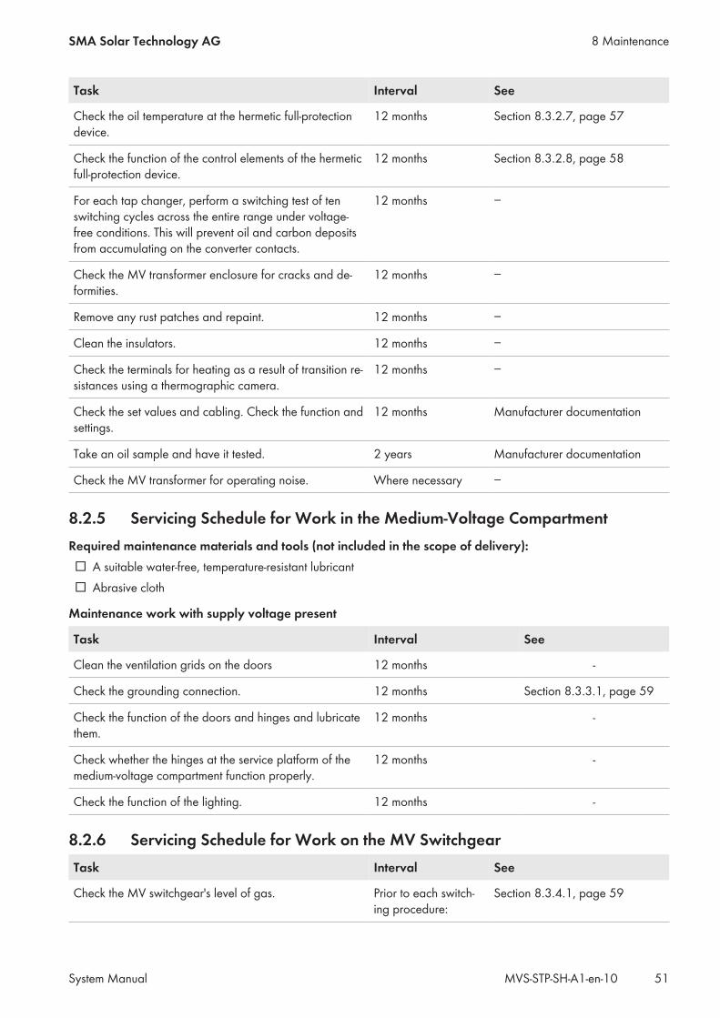
Task Interval See
Check the oil temperature at the hermetic full-protectiondevice.
12 months Section 8.3.2.7, page 57
Check the function of the control elements of the hermeticfull-protection device.
12 months Section 8.3.2.8, page 58
For each tap changer, perform a switching test of tenswitching cycles across the entire range under voltage-free conditions. This will prevent oil and carbon depositsfrom accumulating on the converter contacts.
12 months −
Check the MV transformer enclosure for cracks and de-formities.
12 months −
Remove any rust patches and repaint. 12 months −
Clean the insulators. 12 months −
Check the terminals for heating as a result of transition re-sistances using a thermographic camera.
12 months −
Check the set values and cabling. Check the function andsettings.
12 months Manufacturer documentation
Take an oil sample and have it tested. 2 years Manufacturer documentation
Check the MV transformer for operating noise. Where necessary −
8.2.5 Servicing Schedule for Work in the Medium-Voltage CompartmentRequired maintenance materials and tools (not included in the scope of delivery):☐ A suitable water-free, temperature-resistant lubricant☐ Abrasive cloth
Maintenance work with supply voltage present
Task Interval See
Clean the ventilation grids on the doors 12 months -
Check the grounding connection. 12 months Section 8.3.3.1, page 59
Check the function of the doors and hinges and lubricatethem.
12 months -
Check whether the hinges at the service platform of themedium-voltage compartment function properly.
12 months -
Check the function of the lighting. 12 months -
8.2.6 Servicing Schedule for Work on the MV SwitchgearTask Interval See
Check the MV switchgear's level of gas. Prior to each switch-ing procedure:
Section 8.3.4.1, page 59
8 MaintenanceSMA Solar Technology AG
System Manual 51MVS-STP-SH-A1-en-10
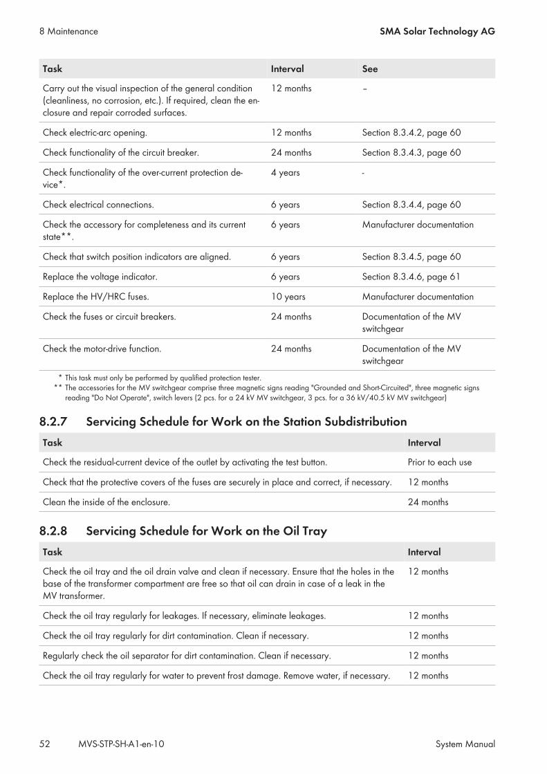
Task Interval See
Carry out the visual inspection of the general condition(cleanliness, no corrosion, etc.). If required, clean the en-closure and repair corroded surfaces.
12 months ‒
Check electric-arc opening. 12 months Section 8.3.4.2, page 60
Check functionality of the circuit breaker. 24 months Section 8.3.4.3, page 60
Check functionality of the over-current protection de-vice*.
4 years -
Check electrical connections. 6 years Section 8.3.4.4, page 60
Check the accessory for completeness and its currentstate**.
6 years Manufacturer documentation
Check that switch position indicators are aligned. 6 years Section 8.3.4.5, page 60
Replace the voltage indicator. 6 years Section 8.3.4.6, page 61
Replace the HV/HRC fuses. 10 years Manufacturer documentation
Check the fuses or circuit breakers. 24 months Documentation of the MVswitchgear
Check the motor-drive function. 24 months Documentation of the MVswitchgear
* This task must only be performed by qualified protection tester.** The accessories for the MV switchgear comprise three magnetic signs reading "Grounded and Short-Circuited", three magnetic signs
reading "Do Not Operate", switch levers (2 pcs. for a 24 kV MV switchgear, 3 pcs. for a 36 kV/40.5 kV MV switchgear)
8.2.7 Servicing Schedule for Work on the Station SubdistributionTask Interval
Check the residual-current device of the outlet by activating the test button. Prior to each use
Check that the protective covers of the fuses are securely in place and correct, if necessary. 12 months
Clean the inside of the enclosure. 24 months
8.2.8 Servicing Schedule for Work on the Oil TrayTask Interval
Check the oil tray and the oil drain valve and clean if necessary. Ensure that the holes in thebase of the transformer compartment are free so that oil can drain in case of a leak in theMV transformer.
12 months
Check the oil tray regularly for leakages. If necessary, eliminate leakages. 12 months
Check the oil tray regularly for dirt contamination. Clean if necessary. 12 months
Regularly check the oil separator for dirt contamination. Clean if necessary. 12 months
Check the oil tray regularly for water to prevent frost damage. Remove water, if necessary. 12 months
8 Maintenance SMA Solar Technology AG
System ManualMVS-STP-SH-A1-en-1052
If the product is subject to adverse ambient conditions, SMA Solar Technology AG recommends that the maintenanceinterval be reduced in accordance with the ambient conditions.
8.3 Maintenance Work
8.3.1 General Maintenance WorkThe general maintenance work must be performed on all components of the product according to the requiredintervals (see Section 8.2.1, page 49).
8.3.1.1 Maintaining the Seals
Required maintenance material (not included in the scope of delivery):☐ Talcum, petroleum jelly or wax for maintaining the seals
Danger to life due to applied voltagesHigh voltages are present in the live components of the product. Touching live components results in death or seriousinjury due to electric shock.
• Always disconnect the product from voltage sources if no voltage is necessary for working on the product (seeSection 6, page 41).
• Always wear personal protective equipment for any work on the product.• Always perform all work in accordance with the locally applicable standards, directives and laws.• Do not touch any live components.• Observe all warning messages on the product and in the documentation.
Procedure:1. Check whether the seals in the sealing area of the enclosure opening show any signs of damage.
If seals are damaged, contact us (see Section 13, page 77).2. Apply talcum, petroleum jelly or wax to seals. This will prevent frost damage.
8.3.1.2 Performing the Visual Inspection
Required maintenance material (included in the scope of delivery):☐ For touching up paintwork damage RAL color 7004. Observe the relevant instructions of the paint manufacturer.
Required maintenance material (not included in the scope of delivery):☐ Abrasive cloth☐ Degreaser☐ Use touch-up stick in the RAL color 7004 to repair small-area surface damage. Observe the relevant instructions of
the paint manufacturer.
8 MaintenanceSMA Solar Technology AG
System Manual 53MVS-STP-SH-A1-en-10
Danger to life due to applied voltagesHigh voltages are present in the live components of the product. Touching live components results in death or seriousinjury due to electric shock.
• Always disconnect the product from voltage sources if no voltage is necessary for working on the product (seeSection 6, page 41).
• Always wear personal protective equipment for any work on the product.• Always perform all work in accordance with the locally applicable standards, directives and laws.• Do not touch any live components.• Observe all warning messages on the product and in the documentation.
Procedure:1. Check all surfaces for dirt. Remove dirt (if necessary).2. Ensure that there are no foreign materials or objects in or on the product that are flammable or that could
otherwise endanger operational safety. If necessary, remove foreign materials and seal any holes to preventfurther intrusion.
3. Ensure that any structural- or environmental changes, e.g. caused by vegetation growth, landslides or subsequentattachments, continue to comply with the installation requirements.
4. Check whether the type labels are complete and legible.Replace the type label if it is not legible. Contact us (see Section 13, page 77).
5. Check whether the circuit diagram and documentation are complete and legible.If the circuit diagram or documentation is not legible, contact us (see Section 13, page 77).
6. Ensure that there are no objects around the product which prevent the cooling air from circulating.7. Check surfaces for damage or corrosion.
If the surfaces are damaged or corroded, repair them without delay or within three weeks at the latest.8. Procedure for affected area:
• Sand the surface.• Clean the surface with degreaser.• Paint the surface.
8.3.1.3 Checking the Latches, Door Stops and Hinges
Required maintenance material (not included in the scope of delivery):☐ A suitable water-free, heat-resistant lubricant, e.g. WD40☐ Non-greasing antifreeze agent, e.g. PS88
Danger to life due to electric shock or electric arc if live components are touchedIf the MV Station and its devices are not correctly disconnected, dangerous voltages may be present in thecomponents which, if touched, will result in death or serious injury.
• Disconnect the MV Station (see Section 6.2, page 42).• Ensure that the MV Station and its devices are voltage-free.
8 Maintenance SMA Solar Technology AG
System ManualMVS-STP-SH-A1-en-1054
Procedure:1. Check whether the doors latch easily. Open and close the doors several times.
If the doors do not latch easily, lubricate all moving parts of the latch.2. Apply lubricant to the hinges on the doors to protect against moisture penetration.
If the door hinges do not move easily, apply lubricant.3. Lubricate all moving parts and movement points.4. Tighten any loose screws with the appropriate torque.5. If the product is installed in regions where below-freezing temperatures occur, apply the non-greasing antifreeze
to the profile cylinder of the door locks and the key switch in order to protect them from icing up.
8.3.1.4 Cleaning the Interior
Danger to life due to applied voltagesHigh voltages are present in the live components of the product. Touching live components results in death or seriousinjury due to electric shock.
• Always disconnect the product from voltage sources if no voltage is necessary for working on the product (seeSection 6, page 41).
• Always wear personal protective equipment for any work on the product.• Always perform all work in accordance with the locally applicable standards, directives and laws.• Do not touch any live components.• Observe all warning messages on the product and in the documentation.
Procedure:1. Remove dirt and dust from all interiors and from all devices.2. Check the interior for leaks.
If leaks are present, fix them.3. Remove moisture.
8.3.1.5 Checking the Labels1. Check whether any warning message or label is damaged or missing.2. Replace any warning messages and labels which are missing or illegible. If necessary, you can order labels from
SMA Solar Technology AG. Contact the Service (see Section 13, page 77).
8.3.2 Maintenance Work on the MV Transformer
8.3.2.1 Checking the Oil Level at the Hermetic Full-Protection Device1. Ensure that the MV transformer and the optional low-voltage disconnection unit and the inverters are disconnected
from all voltage sources (see Section 6, page 41).2. Remove the grids in front of the MV transformer (see Section 10.4, page 67).3. Check the oil level of the MV transformer on the oil level indicator of the hermetic full-protection device. The float
of the oil level indicator must be at the upper stop.If the float is not at the upper stop, contact us (see Section 13, page 77).
4. Remount the grids in front of the MV transformer.
8 MaintenanceSMA Solar Technology AG
System Manual 55MVS-STP-SH-A1-en-10
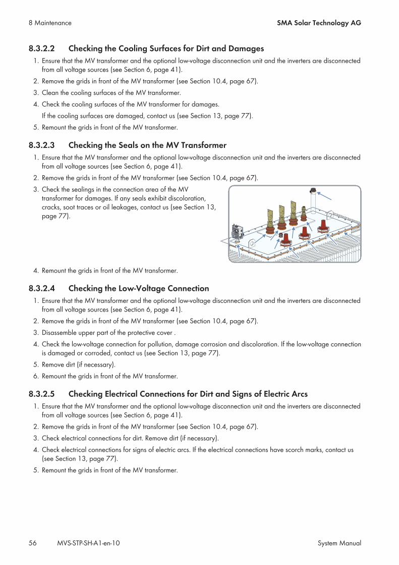
8.3.2.2 Checking the Cooling Surfaces for Dirt and Damages1. Ensure that the MV transformer and the optional low-voltage disconnection unit and the inverters are disconnected
from all voltage sources (see Section 6, page 41).2. Remove the grids in front of the MV transformer (see Section 10.4, page 67).3. Clean the cooling surfaces of the MV transformer.4. Check the cooling surfaces of the MV transformer for damages.
If the cooling surfaces are damaged, contact us (see Section 13, page 77).5. Remount the grids in front of the MV transformer.
8.3.2.3 Checking the Seals on the MV Transformer1. Ensure that the MV transformer and the optional low-voltage disconnection unit and the inverters are disconnected
from all voltage sources (see Section 6, page 41).2. Remove the grids in front of the MV transformer (see Section 10.4, page 67).3. Check the sealings in the connection area of the MV
transformer for damages. If any seals exhibit discoloration,cracks, soot traces or oil leakages, contact us (see Section 13,page 77).
4. Remount the grids in front of the MV transformer.
8.3.2.4 Checking the Low-Voltage Connection1. Ensure that the MV transformer and the optional low-voltage disconnection unit and the inverters are disconnected
from all voltage sources (see Section 6, page 41).2. Remove the grids in front of the MV transformer (see Section 10.4, page 67).3. Disassemble upper part of the protective cover .4. Check the low-voltage connection for pollution, damage corrosion and discoloration. If the low-voltage connection
is damaged or corroded, contact us (see Section 13, page 77).5. Remove dirt (if necessary).6. Remount the grids in front of the MV transformer.
8.3.2.5 Checking Electrical Connections for Dirt and Signs of Electric Arcs1. Ensure that the MV transformer and the optional low-voltage disconnection unit and the inverters are disconnected
from all voltage sources (see Section 6, page 41).2. Remove the grids in front of the MV transformer (see Section 10.4, page 67).3. Check electrical connections for dirt. Remove dirt (if necessary).4. Check electrical connections for signs of electric arcs. If the electrical connections have scorch marks, contact us
(see Section 13, page 77).5. Remount the grids in front of the MV transformer.
8 Maintenance SMA Solar Technology AG
System ManualMVS-STP-SH-A1-en-1056
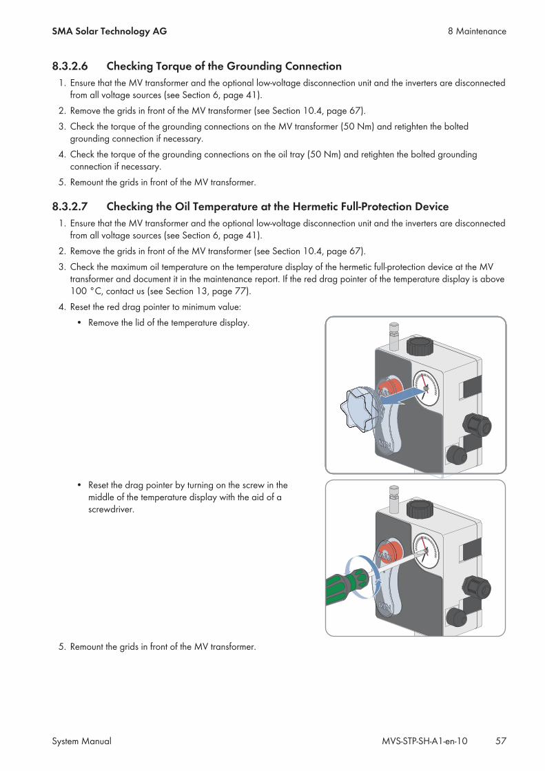
8.3.2.6 Checking Torque of the Grounding Connection1. Ensure that the MV transformer and the optional low-voltage disconnection unit and the inverters are disconnected
from all voltage sources (see Section 6, page 41).2. Remove the grids in front of the MV transformer (see Section 10.4, page 67).3. Check the torque of the grounding connections on the MV transformer (50 Nm) and retighten the bolted
grounding connection if necessary.4. Check the torque of the grounding connections on the oil tray (50 Nm) and retighten the bolted grounding
connection if necessary.5. Remount the grids in front of the MV transformer.
8.3.2.7 Checking the Oil Temperature at the Hermetic Full-Protection Device1. Ensure that the MV transformer and the optional low-voltage disconnection unit and the inverters are disconnected
from all voltage sources (see Section 6, page 41).2. Remove the grids in front of the MV transformer (see Section 10.4, page 67).3. Check the maximum oil temperature on the temperature display of the hermetic full-protection device at the MV
transformer and document it in the maintenance report. If the red drag pointer of the temperature display is above100 °C, contact us (see Section 13, page 77).
4. Reset the red drag pointer to minimum value:• Remove the lid of the temperature display.
• Reset the drag pointer by turning on the screw in themiddle of the temperature display with the aid of ascrewdriver.
5. Remount the grids in front of the MV transformer.
8 MaintenanceSMA Solar Technology AG
System Manual 57MVS-STP-SH-A1-en-10
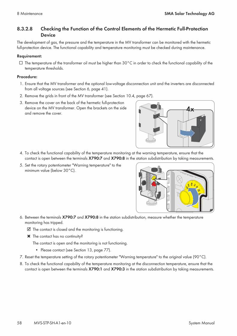
8.3.2.8 Checking the Function of the Control Elements of the Hermetic Full-ProtectionDevice
The development of gas, the pressure and the temperature in the MV transformer can be monitored with the hermeticfull-protection device. The functional capability and temperature monitoring must be checked during maintenance.
Requirement:☐ The temperature of the transformer oil must be higher than 30°C in order to check the functional capability of the
temperature thresholds.
Procedure:1. Ensure that the MV transformer and the optional low-voltage disconnection unit and the inverters are disconnected
from all voltage sources (see Section 6, page 41).2. Remove the grids in front of the MV transformer (see Section 10.4, page 67).3. Remove the cover on the back of the hermetic full-protection
device on the MV transformer. Open the brackets on the sideand remove the cover.
4. To check the functional capability of the temperature monitoring at the warning temperature, ensure that thecontact is open between the terminals X790:7 and X790:8 in the station subdistribution by taking measurements.
5. Set the rotary potentiometer "Warning temperature" to theminimum value (below 30°C).
6. Between the terminals X790:7 and X790:8 in the station subdistribution, measure whether the temperaturemonitoring has tripped.☑ The contact is closed and the monitoring is functioning.✖ The contact has no continuity?
The contact is open and the monitoring is not functioning.• Please contact (see Section 13, page 77).
7. Reset the temperature setting of the rotary potentiometer "Warning temperature" to the original value (90°C).8. To check the functional capability of the temperature monitoring at the disconnection temperature, ensure that the
contact is open between the terminals X790:1 and X790:3 in the station subdistribution by taking measurements.
8 Maintenance SMA Solar Technology AG
System ManualMVS-STP-SH-A1-en-1058

9. Set the rotary potentiometer "Disconnection temperature" to theminimum value (below 30°C).
10. Between the terminals X790:1 and X790:3 in the station subdistribution, measure whether the temperaturemonitoring has tripped.☑ The contact is closed and the monitoring is functioning.✖ The contact has no continuity?
The contact is open and the monitoring is not functioning.• Please contact (see Section 13, page 77).
11. Reset the temperature setting of the rotary potentiometer "Disconnection temperature" to the original value(100°C).
12. Ensure that the setting for monitoring the oil pressure is set to200 mbar.
13. Attach the cover to the back of the hermetic full-protection device on the MV transformer. To do so, put the coverin place and close the brackets on the side.
8.3.3 Maintenance Work in the Medium-Voltage Compartment
8.3.3.1 Checking Grounding Connections1. Ensure that the MV Station is disconnected and grounded (see Section 6, page 41).2. Make sure that the grounding contacts on the grounding busbar inside the medium-voltage compartment are
securely in place and show no discoloration or corrosion. Retighten the grounding contacts (if necessary).If the grounding contacts are discolored or corroded, contact us (see Section 13, page 77).
8.3.4 Maintenance Work on the MV Switchgear
8.3.4.1 Checking the MV Switchgear's Level of GasThe level of SF6 gas must be checked before performing any switching operation.
Procedure:• Check the MV switchgear's level of gas on the manometer.
If the level of SF6 gas is too low, contact us (see Section 13, page 77).
8 MaintenanceSMA Solar Technology AG
System Manual 59MVS-STP-SH-A1-en-10
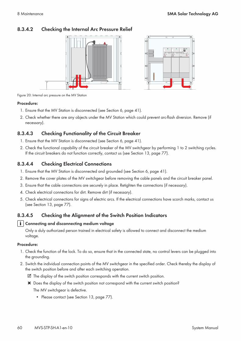
8.3.4.2 Checking the Internal Arc Pressure Relief
Figure 20: Internal arc pressure on the MV Station
Procedure:1. Ensure that the MV Station is disconnected (see Section 6, page 41).2. Check whether there are any objects under the MV Station which could prevent arc-flash diversion. Remove (if
necessary).
8.3.4.3 Checking Functionality of the Circuit Breaker1. Ensure that the MV Station is disconnected (see Section 6, page 41).2. Check the functional capability of the circuit breaker of the MV switchgear by performing 1 to 2 switching cycles.
If the circuit breakers do not function correctly, contact us (see Section 13, page 77).
8.3.4.4 Checking Electrical Connections1. Ensure that the MV Station is disconnected and grounded (see Section 6, page 41).2. Remove the cover plates of the MV switchgear before removing the cable panels and the circuit breaker panel.3. Ensure that the cable connections are securely in place. Retighten the connections (if necessary).4. Check electrical connections for dirt. Remove dirt (if necessary).5. Check electrical connections for signs of electric arcs. If the electrical connections have scorch marks, contact us
(see Section 13, page 77).
8.3.4.5 Checking the Alignment of the Switch Position IndicatorsConnecting and disconnecting medium voltageOnly a duly authorized person trained in electrical safety is allowed to connect and disconnect the mediumvoltage.
Procedure:1. Check the function of the lock. To do so, ensure that in the connected state, no control levers can be plugged into
the grounding.2. Switch the individual connection points of the MV switchgear in the specified order. Check thereby the display of
the switch position before and after each switching operation.☑ The display of the switch position corresponds with the current switch position.✖ Does the display of the switch position not correspond with the current switch position?
The MV switchgear is defective.• Please contact (see Section 13, page 77).
8 Maintenance SMA Solar Technology AG
System ManualMVS-STP-SH-A1-en-1060
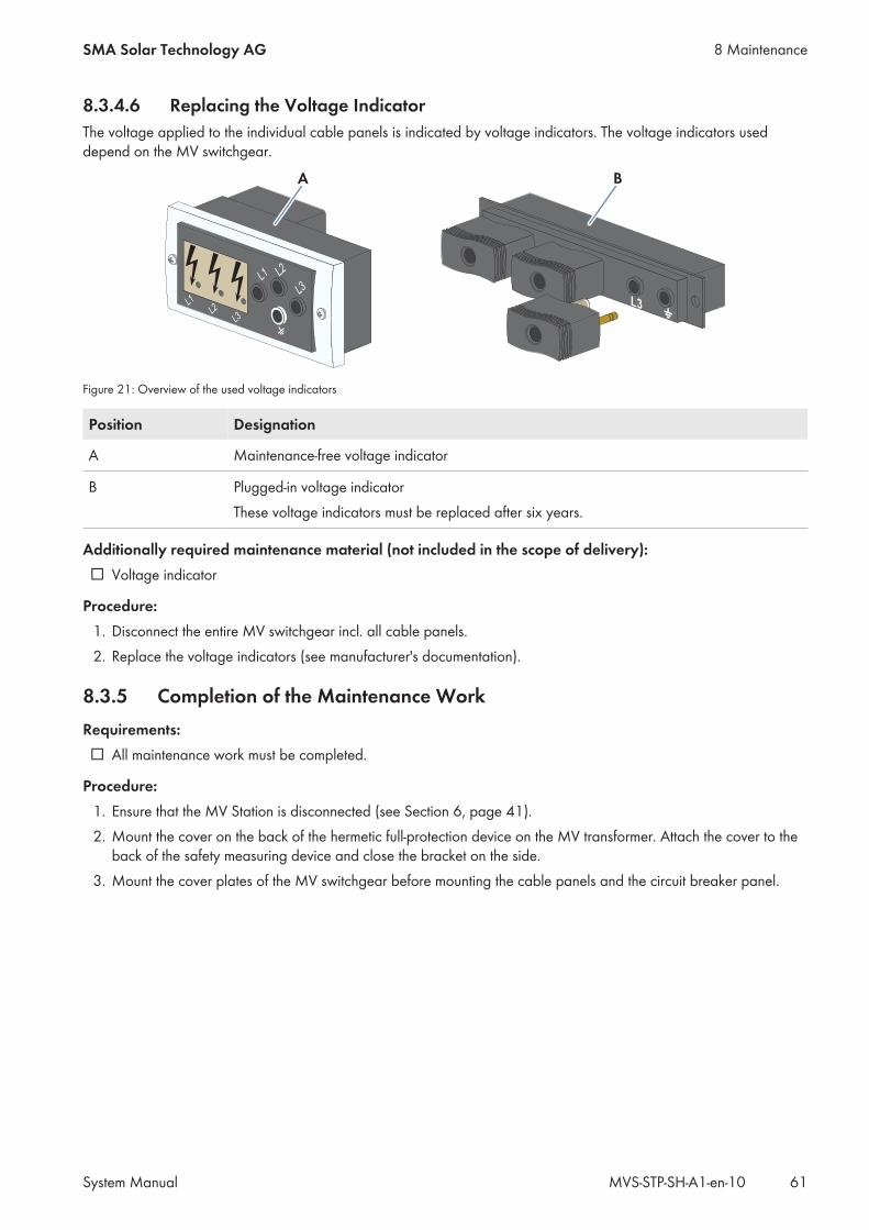
8.3.4.6 Replacing the Voltage IndicatorThe voltage applied to the individual cable panels is indicated by voltage indicators. The voltage indicators useddepend on the MV switchgear.
L1 L2
L3
L1
L2
L3
A
L2
L3
B
Figure 21: Overview of the used voltage indicators
Position Designation
A Maintenance-free voltage indicator
B Plugged-in voltage indicatorThese voltage indicators must be replaced after six years.
Additionally required maintenance material (not included in the scope of delivery):☐ Voltage indicator
Procedure:1. Disconnect the entire MV switchgear incl. all cable panels.2. Replace the voltage indicators (see manufacturer's documentation).
8.3.5 Completion of the Maintenance WorkRequirements:☐ All maintenance work must be completed.
Procedure:1. Ensure that the MV Station is disconnected (see Section 6, page 41).2. Mount the cover on the back of the hermetic full-protection device on the MV transformer. Attach the cover to the
back of the safety measuring device and close the bracket on the side.3. Mount the cover plates of the MV switchgear before mounting the cable panels and the circuit breaker panel.
8 MaintenanceSMA Solar Technology AG
System Manual 61MVS-STP-SH-A1-en-10
9 DisposalProper disposalAn MV Station that has come to the end of its service life is electronic waste. Electronic waste contains on the onehand valuable materials (e.g. copper, aluminum or steel) which can be recycled as secondary raw materials, andon the other, substances which are hazardous to the environment (e.g. oil or SF6 gas). Contact your localcommercial disposal services for information on optimum material utilization and environmentally friendlydisposal.
The sealing plates with which the MV transformer and the cable entries in the medium-voltage compartment are sealedfor the "Sea Freight" option are no longer required after installation and can be introduced into the recyclable materialchain.For further information on disposal and recycling, refer to the respective documentation of the individual devices. Forexample, after the useful life has expired, the SF6 gas used in medium-voltage switchgears must be extractedcompletely and then sent for recycling.We can support you (see Section 13, page 77) in implementing the measures necessary for the disposal andrecycling of the PV power plants.
9 Disposal SMA Solar Technology AG
System ManualMVS-STP-SH-A1-en-1062
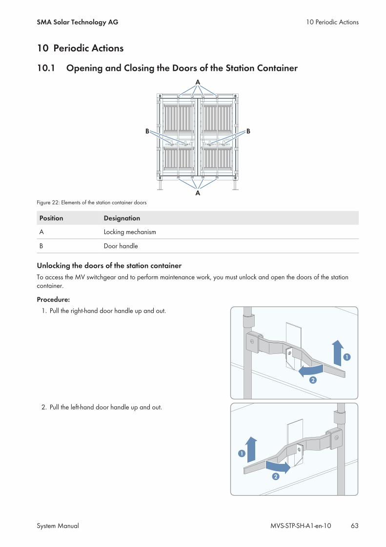
10 Periodic Actions
10.1 Opening and Closing the Doors of the Station Container
B
A
B
A
Figure 22: Elements of the station container doors
Position Designation
A Locking mechanism
B Door handle
Unlocking the doors of the station containerTo access the MV switchgear and to perform maintenance work, you must unlock and open the doors of the stationcontainer.
Procedure:1. Pull the right-hand door handle up and out.
1
2
2. Pull the left-hand door handle up and out.
1
2
10 Periodic ActionsSMA Solar Technology AG
System Manual 63MVS-STP-SH-A1-en-10
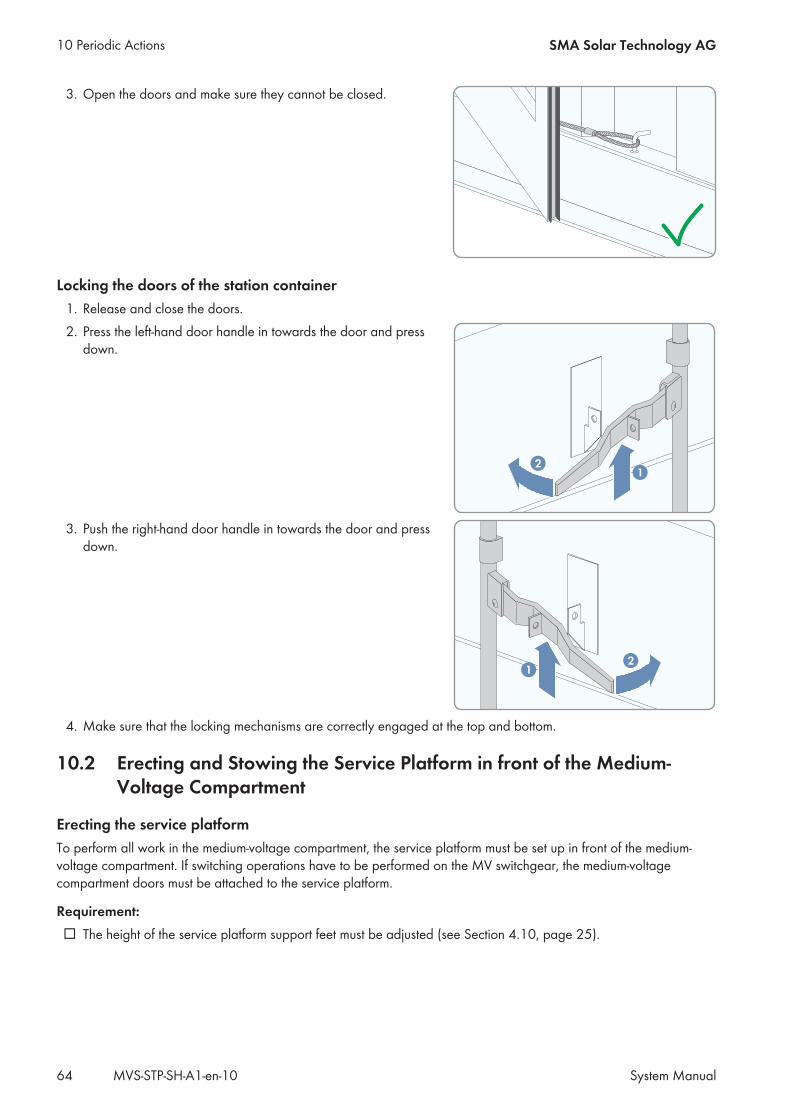
3. Open the doors and make sure they cannot be closed.
Locking the doors of the station container1. Release and close the doors.2. Press the left-hand door handle in towards the door and press
down.
12
3. Push the right-hand door handle in towards the door and pressdown.
12
4. Make sure that the locking mechanisms are correctly engaged at the top and bottom.
10.2 Erecting and Stowing the Service Platform in front of the Medium-Voltage Compartment
Erecting the service platformTo perform all work in the medium-voltage compartment, the service platform must be set up in front of the medium-voltage compartment. If switching operations have to be performed on the MV switchgear, the medium-voltagecompartment doors must be attached to the service platform.
Requirement:☐ The height of the service platform support feet must be adjusted (see Section 4.10, page 25).
10 Periodic Actions SMA Solar Technology AG
System ManualMVS-STP-SH-A1-en-1064
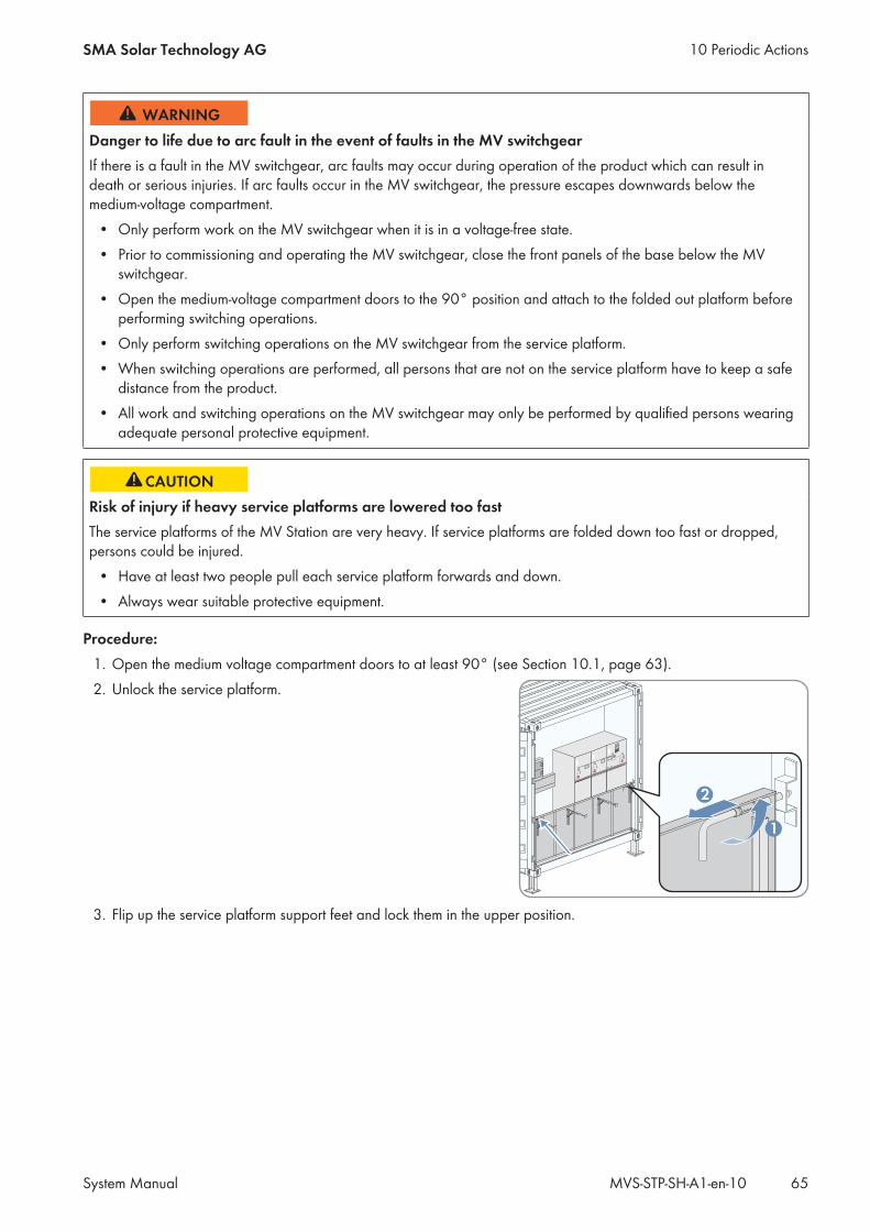
Danger to life due to arc fault in the event of faults in the MV switchgearIf there is a fault in the MV switchgear, arc faults may occur during operation of the product which can result indeath or serious injuries. If arc faults occur in the MV switchgear, the pressure escapes downwards below themedium-voltage compartment.
• Only perform work on the MV switchgear when it is in a voltage-free state.• Prior to commissioning and operating the MV switchgear, close the front panels of the base below the MV
switchgear.• Open the medium-voltage compartment doors to the 90° position and attach to the folded out platform before
performing switching operations.• Only perform switching operations on the MV switchgear from the service platform.• When switching operations are performed, all persons that are not on the service platform have to keep a safe
distance from the product.• All work and switching operations on the MV switchgear may only be performed by qualified persons wearing
adequate personal protective equipment.
Risk of injury if heavy service platforms are lowered too fastThe service platforms of the MV Station are very heavy. If service platforms are folded down too fast or dropped,persons could be injured.
• Have at least two people pull each service platform forwards and down.• Always wear suitable protective equipment.
Procedure:1. Open the medium voltage compartment doors to at least 90° (see Section 10.1, page 63).2. Unlock the service platform.
1
2
3. Flip up the service platform support feet and lock them in the upper position.
10 Periodic ActionsSMA Solar Technology AG
System Manual 65MVS-STP-SH-A1-en-10
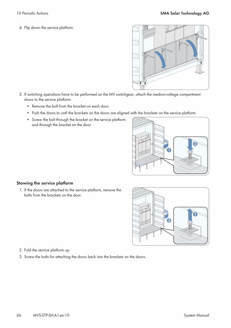
4. Flip down the service platform.
5. If switching operations have to be performed on the MV switchgear, attach the medium-voltage compartmentdoors to the service platform:
• Remove the bolt from the bracket on each door.• Push the doors to until the brackets on the doors are aligned with the brackets on the service platform.• Screw the bolt through the bracket on the service platform
and through the bracket on the door.
2
1
Stowing the service platform1. If the doors are attached to the service platform, remove the
bolts from the brackets on the door.
1
2
2. Fold the service platform up.3. Screw the bolts for attaching the doors back into the brackets on the doors.
10 Periodic Actions SMA Solar Technology AG
System ManualMVS-STP-SH-A1-en-1066
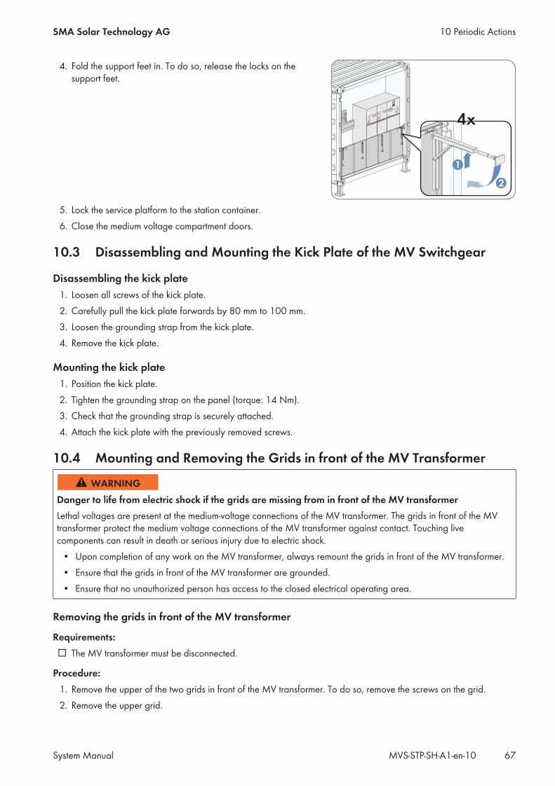
4. Fold the support feet in. To do so, release the locks on thesupport feet.
1
2
4x4x
5. Lock the service platform to the station container.6. Close the medium voltage compartment doors.
10.3 Disassembling and Mounting the Kick Plate of the MV Switchgear
Disassembling the kick plate1. Loosen all screws of the kick plate.2. Carefully pull the kick plate forwards by 80 mm to 100 mm.3. Loosen the grounding strap from the kick plate.4. Remove the kick plate.
Mounting the kick plate1. Position the kick plate.2. Tighten the grounding strap on the panel (torque: 14 Nm).3. Check that the grounding strap is securely attached.4. Attach the kick plate with the previously removed screws.
10.4 Mounting and Removing the Grids in front of the MV Transformer
Danger to life from electric shock if the grids are missing from in front of the MV transformerLethal voltages are present at the medium-voltage connections of the MV transformer. The grids in front of the MVtransformer protect the medium voltage connections of the MV transformer against contact. Touching livecomponents can result in death or serious injury due to electric shock.
• Upon completion of any work on the MV transformer, always remount the grids in front of the MV transformer.• Ensure that the grids in front of the MV transformer are grounded.• Ensure that no unauthorized person has access to the closed electrical operating area.
Removing the grids in front of the MV transformer
Requirements:☐ The MV transformer must be disconnected.
Procedure:1. Remove the upper of the two grids in front of the MV transformer. To do so, remove the screws on the grid.2. Remove the upper grid.
10 Periodic ActionsSMA Solar Technology AG
System Manual 67MVS-STP-SH-A1-en-10
3. Remove the lower grid. To do so, remove the screws on the grid.4. Remove the lower grid.
Mounting the grids in front of the MV transformer1. Mount the lower of the two grids to the station container using the previously removed screws.2. Mount the upper grid to the station container using the previously removed screws.
10 Periodic Actions SMA Solar Technology AG
System ManualMVS-STP-SH-A1-en-1068
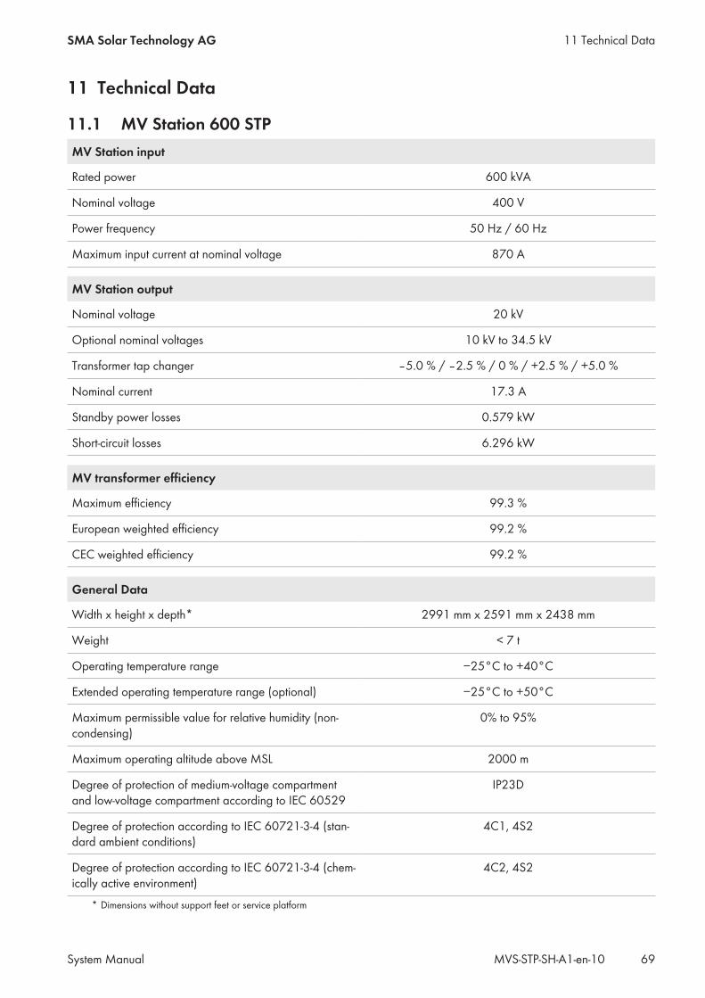
11 Technical Data
11.1 MV Station 600 STPMV Station input
Rated power 600 kVA
Nominal voltage 400 V
Power frequency 50 Hz / 60 Hz
Maximum input current at nominal voltage 870 A
MV Station output
Nominal voltage 20 kV
Optional nominal voltages 10 kV to 34.5 kV
Transformer tap changer ‒5.0 % / ‒2.5 % / 0 % / +2.5 % / +5.0 %
Nominal current 17.3 A
Standby power losses 0.579 kW
Short-circuit losses 6.296 kW
MV transformer efficiency
Maximum efficiency 99.3 %
European weighted efficiency 99.2 %
CEC weighted efficiency 99.2 %
General Data
Width x height x depth* 2991 mm x 2591 mm x 2438 mm
Weight < 7 t
Operating temperature range −25°C to +40°C
Extended operating temperature range (optional) −25°C to +50°C
Maximum permissible value for relative humidity (non-condensing)
0% to 95%
Maximum operating altitude above MSL 2000 m
Degree of protection of medium-voltage compartmentand low-voltage compartment according to IEC 60529
IP23D
Degree of protection according to IEC 60721-3-4 (stan-dard ambient conditions)
4C1, 4S2
Degree of protection according to IEC 60721-3-4 (chem-ically active environment)
4C2, 4S2
* Dimensions without support feet or service platform
11 Technical DataSMA Solar Technology AG
System Manual 69MVS-STP-SH-A1-en-10
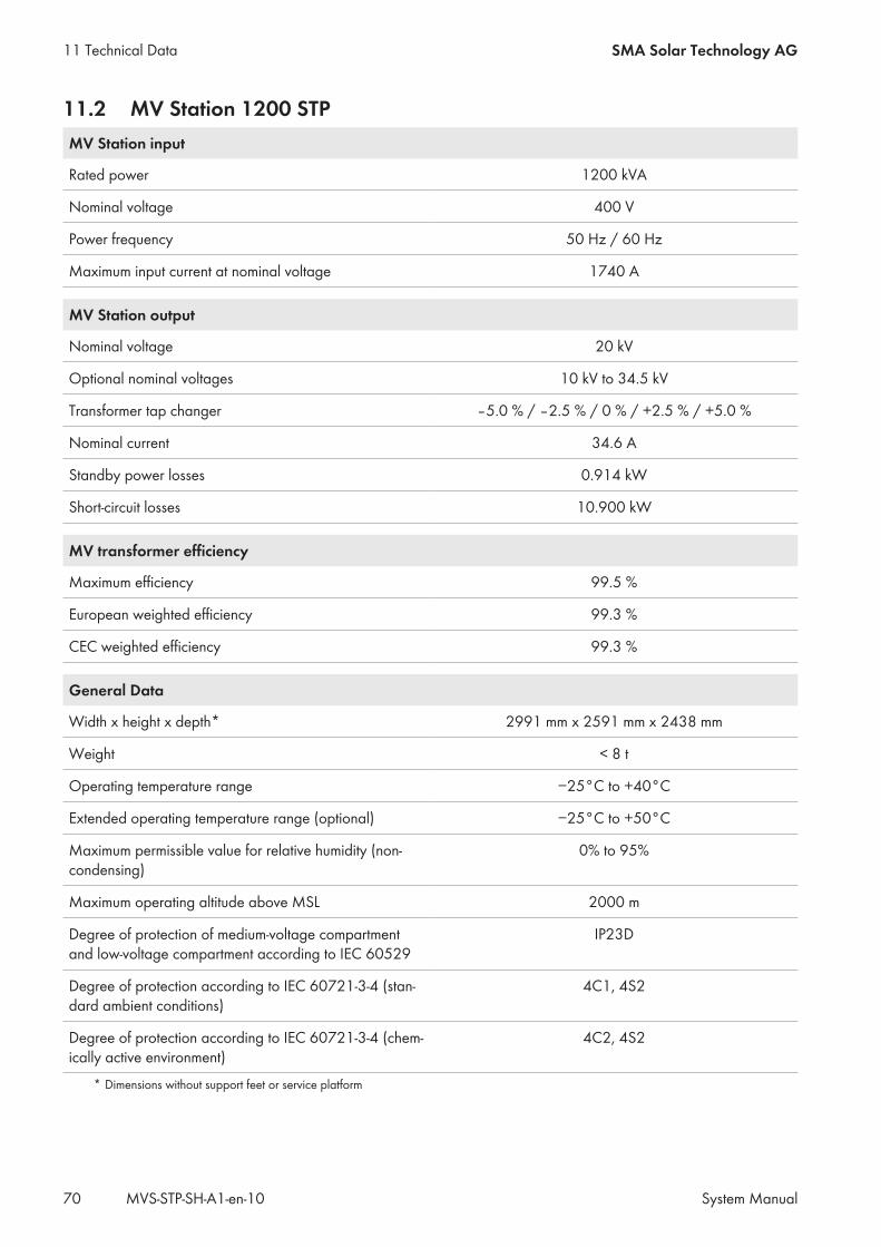
11.2 MV Station 1200 STPMV Station input
Rated power 1200 kVA
Nominal voltage 400 V
Power frequency 50 Hz / 60 Hz
Maximum input current at nominal voltage 1740 A
MV Station output
Nominal voltage 20 kV
Optional nominal voltages 10 kV to 34.5 kV
Transformer tap changer ‒5.0 % / ‒2.5 % / 0 % / +2.5 % / +5.0 %
Nominal current 34.6 A
Standby power losses 0.914 kW
Short-circuit losses 10.900 kW
MV transformer efficiency
Maximum efficiency 99.5 %
European weighted efficiency 99.3 %
CEC weighted efficiency 99.3 %
General Data
Width x height x depth* 2991 mm x 2591 mm x 2438 mm
Weight < 8 t
Operating temperature range −25°C to +40°C
Extended operating temperature range (optional) −25°C to +50°C
Maximum permissible value for relative humidity (non-condensing)
0% to 95%
Maximum operating altitude above MSL 2000 m
Degree of protection of medium-voltage compartmentand low-voltage compartment according to IEC 60529
IP23D
Degree of protection according to IEC 60721-3-4 (stan-dard ambient conditions)
4C1, 4S2
Degree of protection according to IEC 60721-3-4 (chem-ically active environment)
4C2, 4S2
* Dimensions without support feet or service platform
11 Technical Data SMA Solar Technology AG
System ManualMVS-STP-SH-A1-en-1070
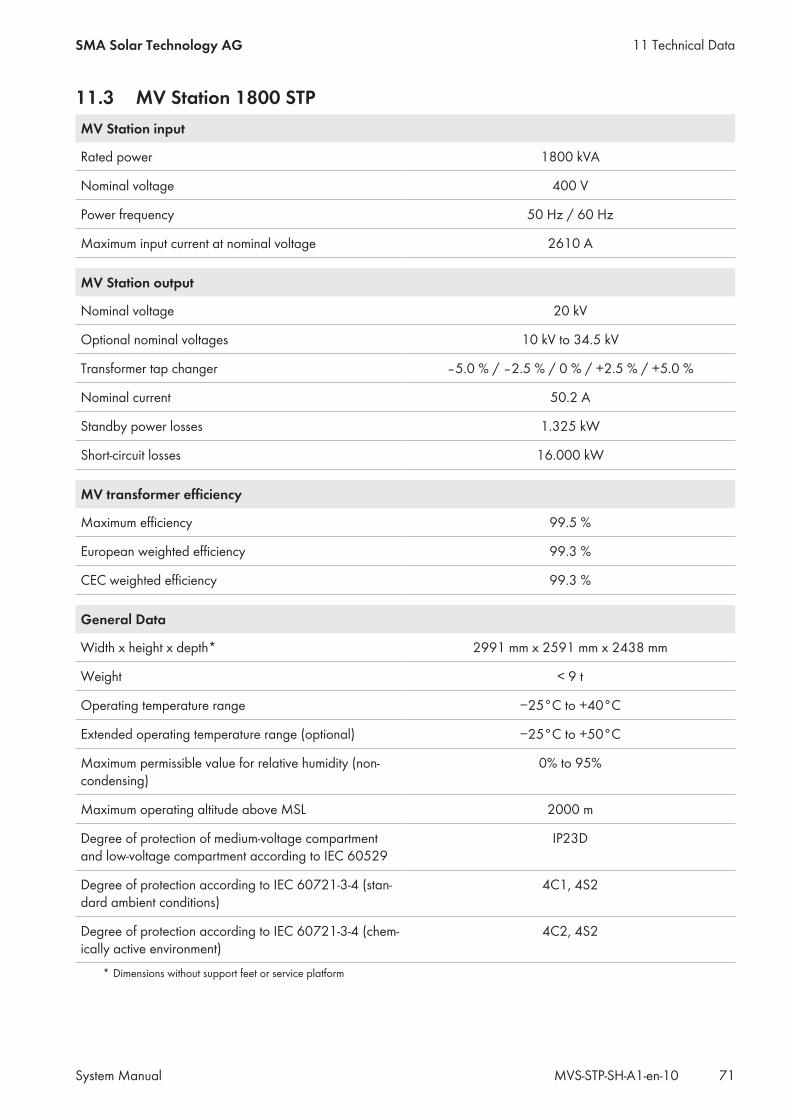
11.3 MV Station 1800 STPMV Station input
Rated power 1800 kVA
Nominal voltage 400 V
Power frequency 50 Hz / 60 Hz
Maximum input current at nominal voltage 2610 A
MV Station output
Nominal voltage 20 kV
Optional nominal voltages 10 kV to 34.5 kV
Transformer tap changer ‒5.0 % / ‒2.5 % / 0 % / +2.5 % / +5.0 %
Nominal current 50.2 A
Standby power losses 1.325 kW
Short-circuit losses 16.000 kW
MV transformer efficiency
Maximum efficiency 99.5 %
European weighted efficiency 99.3 %
CEC weighted efficiency 99.3 %
General Data
Width x height x depth* 2991 mm x 2591 mm x 2438 mm
Weight < 9 t
Operating temperature range −25°C to +40°C
Extended operating temperature range (optional) −25°C to +50°C
Maximum permissible value for relative humidity (non-condensing)
0% to 95%
Maximum operating altitude above MSL 2000 m
Degree of protection of medium-voltage compartmentand low-voltage compartment according to IEC 60529
IP23D
Degree of protection according to IEC 60721-3-4 (stan-dard ambient conditions)
4C1, 4S2
Degree of protection according to IEC 60721-3-4 (chem-ically active environment)
4C2, 4S2
* Dimensions without support feet or service platform
11 Technical DataSMA Solar Technology AG
System Manual 71MVS-STP-SH-A1-en-10
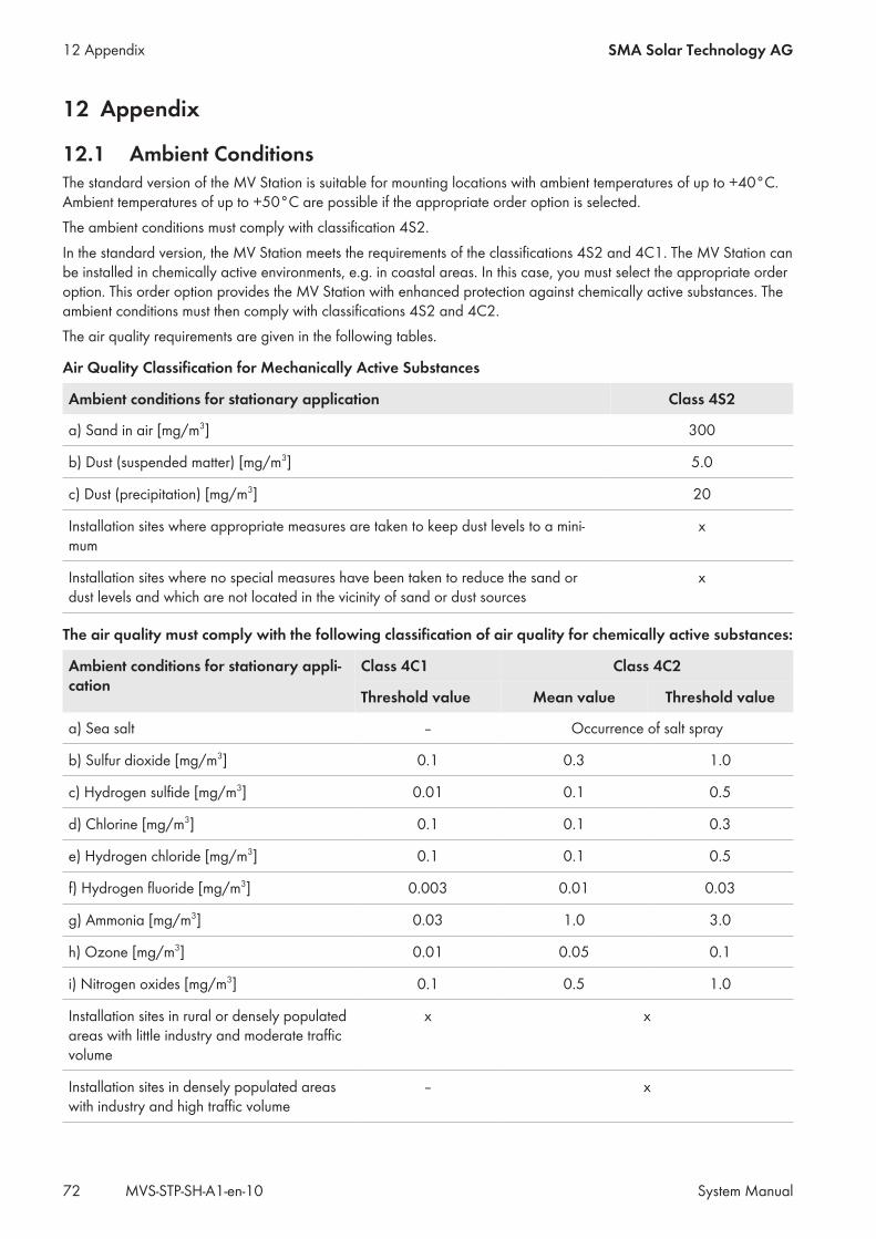
12 Appendix
12.1 Ambient ConditionsThe standard version of the MV Station is suitable for mounting locations with ambient temperatures of up to +40°C.Ambient temperatures of up to +50°C are possible if the appropriate order option is selected.The ambient conditions must comply with classification 4S2.In the standard version, the MV Station meets the requirements of the classifications 4S2 and 4C1. The MV Station canbe installed in chemically active environments, e.g. in coastal areas. In this case, you must select the appropriate orderoption. This order option provides the MV Station with enhanced protection against chemically active substances. Theambient conditions must then comply with classifications 4S2 and 4C2.The air quality requirements are given in the following tables.
Air Quality Classification for Mechanically Active Substances
Ambient conditions for stationary application Class 4S2
a) Sand in air [mg/m3] 300
b) Dust (suspended matter) [mg/m3] 5.0
c) Dust (precipitation) [mg/m3] 20
Installation sites where appropriate measures are taken to keep dust levels to a mini-mum
x
Installation sites where no special measures have been taken to reduce the sand ordust levels and which are not located in the vicinity of sand or dust sources
x
The air quality must comply with the following classification of air quality for chemically active substances:
Ambient conditions for stationary appli-cation
Class 4C1 Class 4C2
Mean value Threshold valueThreshold value
a) Sea salt ‒ Occurrence of salt spray
b) Sulfur dioxide [mg/m3] 0.1 0.3 1.0
c) Hydrogen sulfide [mg/m3] 0.01 0.1 0.5
d) Chlorine [mg/m3] 0.1 0.1 0.3
e) Hydrogen chloride [mg/m3] 0.1 0.1 0.5
f) Hydrogen fluoride [mg/m3] 0.003 0.01 0.03
g) Ammonia [mg/m3] 0.03 1.0 3.0
h) Ozone [mg/m3] 0.01 0.05 0.1
i) Nitrogen oxides [mg/m3] 0.1 0.5 1.0
Installation sites in rural or densely populatedareas with little industry and moderate trafficvolume
x x
Installation sites in densely populated areaswith industry and high traffic volume
‒ x
12 Appendix SMA Solar Technology AG
System ManualMVS-STP-SH-A1-en-1072
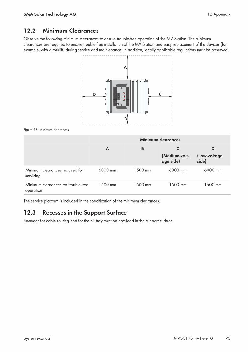
12.2 Minimum ClearancesObserve the following minimum clearances to ensure trouble-free operation of the MV Station. The minimumclearances are required to ensure trouble-free installation of the MV Station and easy replacement of the devices (forexample, with a forklift) during service and maintenance. In addition, locally applicable regulations must be observed.
A
B
CD
Figure 23: Minimum clearances
Minimum clearances
A B C(Medium-volt-age side)
D(Low-voltageside)
Minimum clearances required forservicing
6000 mm 1500 mm 6000 mm 6000 mm
Minimum clearances for trouble-freeoperation
1500 mm 1500 mm 1500 mm 1500 mm
The service platform is included in the specification of the minimum clearances.
12.3 Recesses in the Support SurfaceRecesses for cable routing and for the oil tray must be provided in the support surface.
12 AppendixSMA Solar Technology AG
System Manual 73MVS-STP-SH-A1-en-10
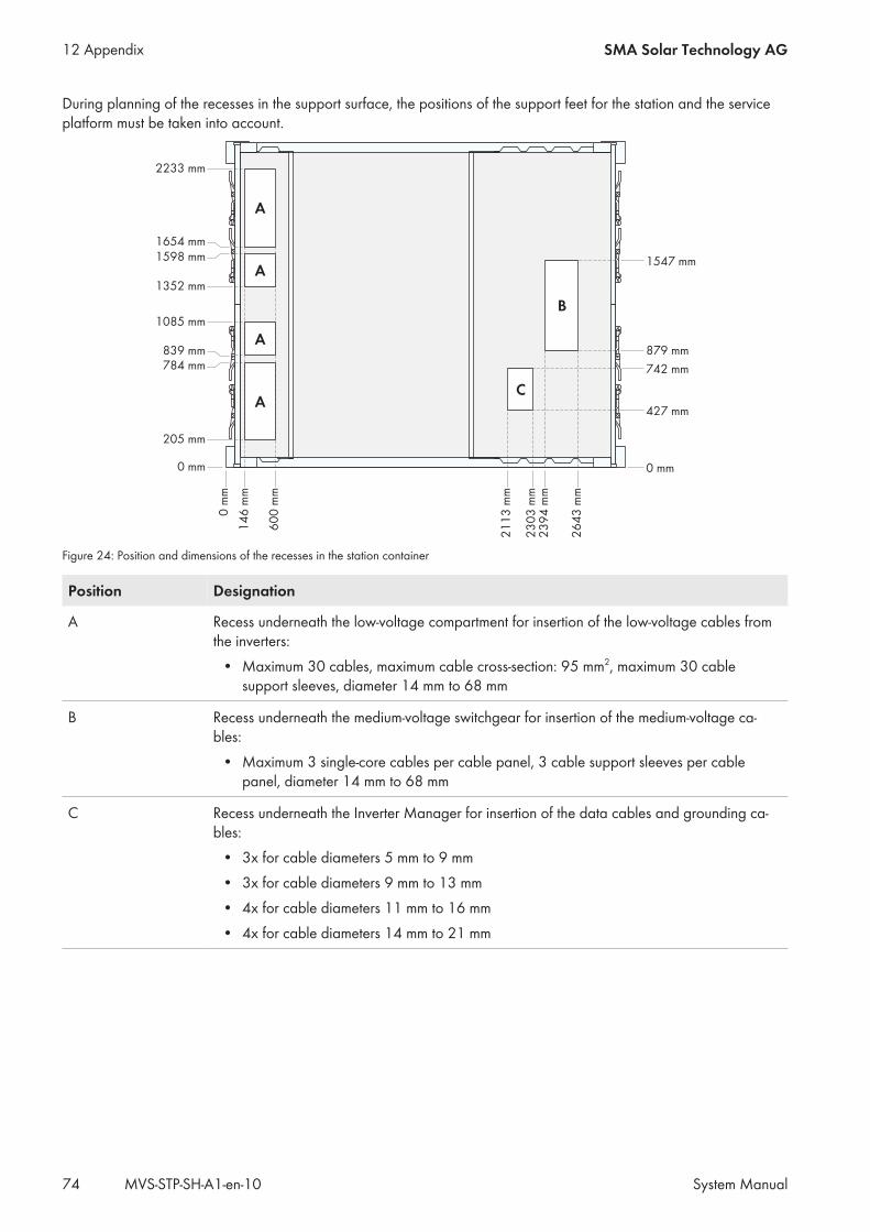
During planning of the recesses in the support surface, the positions of the support feet for the station and the serviceplatform must be taken into account.
60
0 m
m
21
13
mm
23
03
mm
23
94
mm
26
43
mm
14
6 m
m
742 mm
879 mm
1547 mm
427 mm
784 mm
839 mm
1085 mm
205 mm
1352 mm
1598 mm
1654 mm
2233 mm
A
A
A
A
B
C
0 mm0 mm
0 m
m
Figure 24: Position and dimensions of the recesses in the station container
Position Designation
A Recess underneath the low-voltage compartment for insertion of the low-voltage cables fromthe inverters:
• Maximum 30 cables, maximum cable cross-section: 95 mm2, maximum 30 cablesupport sleeves, diameter 14 mm to 68 mm
B Recess underneath the medium-voltage switchgear for insertion of the medium-voltage ca-bles:
• Maximum 3 single-core cables per cable panel, 3 cable support sleeves per cablepanel, diameter 14 mm to 68 mm
C Recess underneath the Inverter Manager for insertion of the data cables and grounding ca-bles:
• 3x for cable diameters 5 mm to 9 mm• 3x for cable diameters 9 mm to 13 mm• 4x for cable diameters 11 mm to 16 mm• 4x for cable diameters 14 mm to 21 mm
12 Appendix SMA Solar Technology AG
System ManualMVS-STP-SH-A1-en-1074
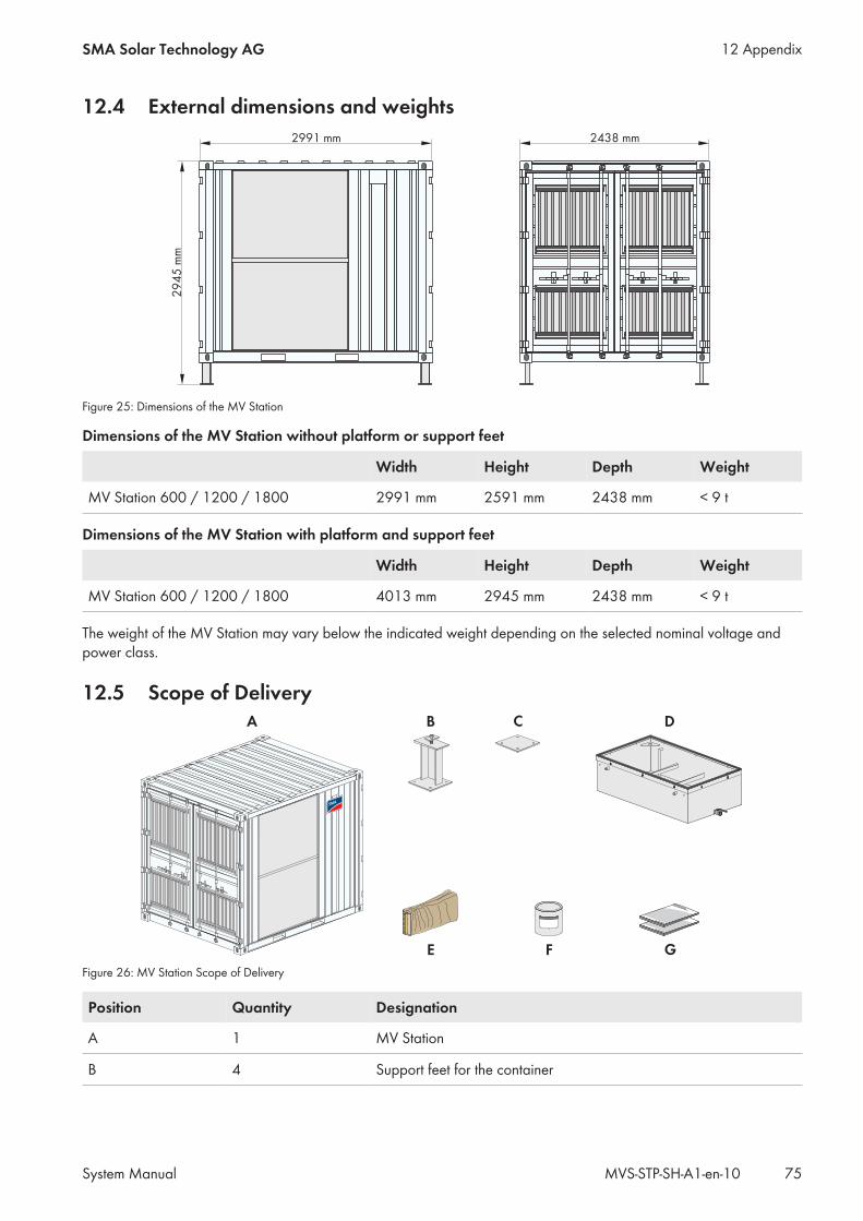
12.4 External dimensions and weights
29
45
mm
2991 mm 2438 mm
Figure 25: Dimensions of the MV Station
Dimensions of the MV Station without platform or support feet
Width Height Depth Weight
MV Station 600 / 1200 / 1800 2991 mm 2591 mm 2438 mm < 9 t
Dimensions of the MV Station with platform and support feet
Width Height Depth Weight
MV Station 600 / 1200 / 1800 4013 mm 2945 mm 2438 mm < 9 t
The weight of the MV Station may vary below the indicated weight depending on the selected nominal voltage andpower class.
12.5 Scope of Delivery
F
CA
G
B
E
D
Figure 26: MV Station Scope of Delivery
Position Quantity Designation
A 1 MV Station
B 4 Support feet for the container
12 AppendixSMA Solar Technology AG
System Manual 75MVS-STP-SH-A1-en-10
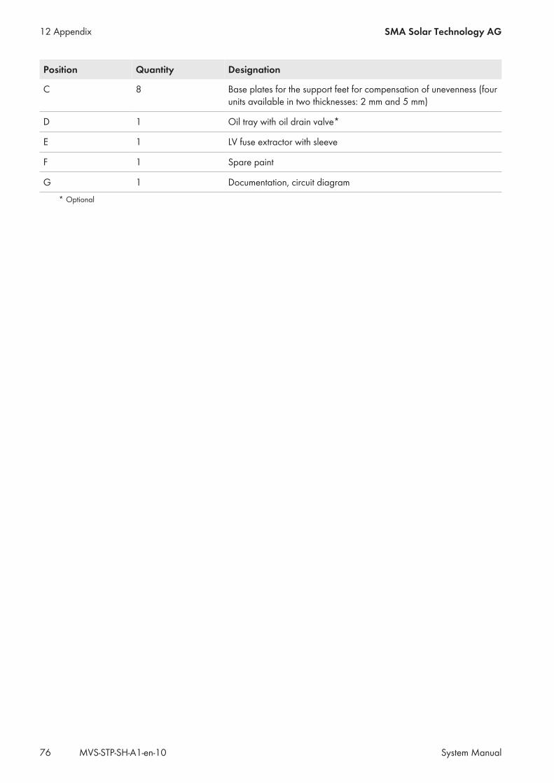
Position Quantity Designation
C 8 Base plates for the support feet for compensation of unevenness (fourunits available in two thicknesses: 2 mm and 5 mm)
D 1 Oil tray with oil drain valve*
E 1 LV fuse extractor with sleeve
F 1 Spare paint
G 1 Documentation, circuit diagram* Optional
12 Appendix SMA Solar Technology AG
System ManualMVS-STP-SH-A1-en-1076
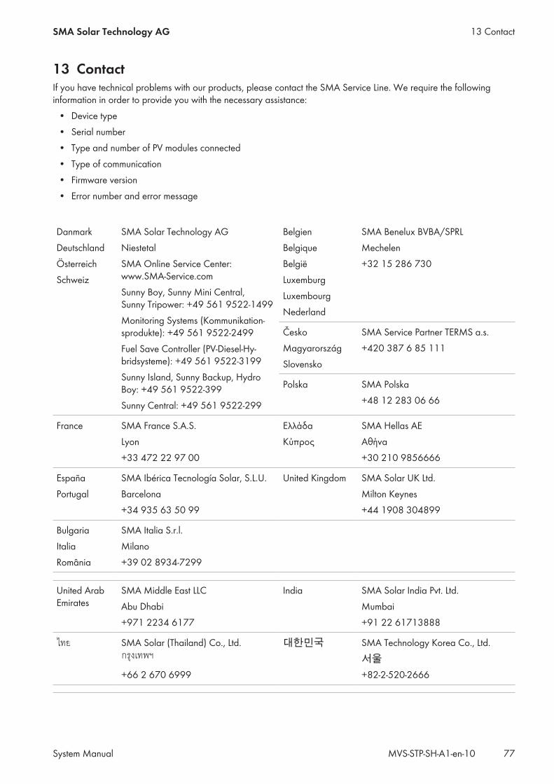
13 ContactIf you have technical problems with our products, please contact the SMA Service Line. We require the followinginformation in order to provide you with the necessary assistance:
• Device type• Serial number• Type and number of PV modules connected• Type of communication• Firmware version• Error number and error message
DanmarkDeutschlandÖsterreichSchweiz
SMA Solar Technology AGNiestetalSMA Online Service Center:www.SMA-Service.comSunny Boy, Sunny Mini Central,Sunny Tripower: +49 561 9522‑1499Monitoring Systems (Kommunikation-sprodukte): +49 561 9522‑2499Fuel Save Controller (PV-Diesel-Hy-bridsysteme): +49 561 9522-3199Sunny Island, Sunny Backup, HydroBoy: +49 561 9522-399Sunny Central: +49 561 9522-299
BelgienBelgiqueBelgiëLuxemburgLuxembourgNederland
SMA Benelux BVBA/SPRLMechelen+32 15 286 730
ČeskoMagyarországSlovensko
SMA Service Partner TERMS a.s.+420 387 6 85 111
Polska SMA Polska+48 12 283 06 66
France SMA France S.A.S.Lyon+33 472 22 97 00
ΕλλάδαΚύπρος
SMA Hellas AEΑθήνα+30 210 9856666
EspañaPortugal
SMA Ibérica Tecnología Solar, S.L.U.Barcelona+34 935 63 50 99
United Kingdom SMA Solar UK Ltd.Milton Keynes+44 1908 304899
BulgariaItaliaRomânia
SMA Italia S.r.l.Milano+39 02 8934-7299
United ArabEmirates
SMA Middle East LLCAbu Dhabi+971 2234 6177
India SMA Solar India Pvt. Ltd.Mumbai+91 22 61713888
SMA Solar (Thailand) Co., Ltd.
+66 2 670 6999
대한민국 SMA Technology Korea Co., Ltd.서울+82-2-520-2666
13 ContactSMA Solar Technology AG
System Manual 77MVS-STP-SH-A1-en-10
South Africa SMA Solar Technology South AfricaPty Ltd.Cape Town08600SUNNY (08600 78669)International: +27 (0)21 826 0600
ArgentinaBrasilChilePerú
SMA South America SPASantiago+562 2820 2101
Australia SMA Australia Pty Ltd.SydneyToll free for Australia: 1800 SMA AUS(1800 762 287)International: +61 2 9491 4200
Other countries International SMA Service LineNiestetalToll free worldwide:00800 SMA SERVICE(+800 762 7378423)
13 Contact SMA Solar Technology AG
System ManualMVS-STP-SH-A1-en-1078


www.SMA-Solar.com