Embed Size (px)
Citation preview
Structural Erlgineeritlg ancl Mechanics, I'r,l. 34, No. 3 (2010) 351-366
System identification of steel framed structures with semi-rigid connections
Hasan N. Katkhudat, Hazim M. Dwairi and Nasim Shatarat
Civil Engineerirtg Deparfnlent, The Hashernite University, Zarqa 13115, Jordatl
(Received Apr.il 6, 2009, Acci2pt~d November 12, 2009)
Abstract. A novcl system identification and structural hcalth assessment proccdurc of steel finn~ed structures with semi-rigid connectiol~s is prescntecl in tliis paper. It is capable of ilctecting damages at the local elc~ncr~t level under nonnal operating conditions; i.e., serviceability limit state. The procedure is a linear time-domain system identification tecllnique in which the structure responses arc required, whereas the dynamic excitation force is not recluircd to identifjl thc strtlctural parameters. The procedure hacks changcs in the stiffiiess properties of all the elements in a stnlcture. It can identify damage-frec ancl (lamaged stnictural elemenls vely accurately whcn excited by different types of' dy~ramie loadings. 'l'he method is elaborated witli the llclp of' several numerical examples. Tlle results indicate that the proposed i~lgoritll~n identified tlle structures correctly and detected the prc-imposed danlages in the frames when excited hy earthquake, impact, and harmonic loadings. '1:Ile algorithm can potentially be used for structural llealtli asse,ss~rie~~t and monitoring of existing shxctures witli lninimum clisnlption of operations. Since the procedure requires only a few time points of response infotmation, it is cxpccted to be economic and efficient.
Keywords: structural health assessment; sctni-rigitl connections; system identification; unk~lown dynamic force. -- - --
I. Introduction
The current state of practice in seislnic design such as, UBC-97 (1997), Eurocode 8 (1998), IBC2006 (2000), aiid MSIITO (1998), infers that preventing collapse and loss of life is its main ol~ject~ve. However, econo~nic losses due to seismic hazard are extensive and have never bee11 acldressed In current cotlcs. 'rherefore, ncw design methotlologies are emerging to accollnt for desigl~ ob-jectives other than loss of life, one such melliod is pcrfo~-rnancc-based seismic design (PRSL)). I'rimarily, PBSD is to tlesign a slructure to acliieve preselected perfo~mance objectives in correspondel~ce lo cerlain seismic hazard levels. PBSD is not limited to design of new builtlings, rather can be usetl to evalnate existing stn~chrres a r ~ d o r retrofit, to reliable perfonnalice ol~jectives. The dccision of whether the slmclure is in need [or rehabilitation or not after a major loading event, such as niajor earthcluake, recluires in fonna l io~~ about the health oC the str~icture aftenvartls. Existing structures call also deteriorate as they age due to other dynamic loadings s1ic11 as, wind gusts,
I i Assistant I'rofessor, Corresponding author, E-mail: [email protected]~~.jo
explosions and rrlachi~le excitations, which all can cause stifliiess ancWor strength degradation to a ccrtain level. Therefore, l~ealth n~o~litoring of existing slructures to identify the state of the struclurc: and to detect the damage whcn it occurs has recently become an important and cl-iallenging issue to tlie engineering profession. Extensive review of the literature on health monitoring can be found in (Doebling et al. 1996, Iiousner el 01. 1997).
The state of the stn~ctural system can be identified using a system identification (SI) techniclue. The available SI techniques can be broadly divided into two categories: frequency dolnain and time domain.
In the Crequcricy ciomain approaches (Vestroni ant1 Capecchi 2000, 1,am et a/. 2004, Kanwar cl 01. 2007), the structural parameters can bc described in terms of dynamic properties, such as frequencies and mode shapes; the changes in these dynamic properties can be utilized to detect level of deterioration. Since frequency represents a global structural property, frequency donlain procedures cannot predict the structural health at the element level, rather than are appropriate to predict whether the overall structure is damaged or not. It has been observed that local darn a g e 1s '
not always sensitive to tlle identified modal properties. In addition, for large, coinplicated structural systems, the higher order n~odes are difficult to evaluate accurately.
In the time domain approaches (Ma et a/. 2005, Koli el nl. 2006, Rutherford et 01. 2005, Ta el 01. 2006), dynamic output response ineasurcments can be used to identify the struct~~ral parameters, such as stiffness, and detect damages by tracking the changes in these responses. The least square- based approaches are very common in [lie time domain (Yang and Lin 2005, Yang et a[. 2007), where the unknown parameters of stiuctural systenls arc estimated by minimizing tllc sum of squared errors between the predicted and the measured outputs. Extendetl Kalrnan filter (EKF) is another successfi~l technique for st~.uctural identiiication in time domain approaches, liowever it requires n known dynamic excitation force ( M n g and Haldar 1997, Yang et al. 2006, 2007). EKF is an optimal recursive data proccssing algoritlim which processes the available response measurements, regardless of their precision. The algoritlln~ uscs the prior knowledge about the system anti limited response information to produce an estimation of the desired variables by statistically minimizing the error.
In 1994, Wang and I-laldar (1994) establisheti a conceptual kamework for a ST approach without knowing tile dynamic excitation force. Tl~cy called it the iterative least squarc wit11 ~~nknown input (11,s-UI) method. They identified shear type buildings (girderslfloors are assumed to be infinitely rigid compared with the columns), which is the simplest ~nattiematical represc~ltation of coniplicated structural systerns. The total inass o f the structure is lumped at tlie floor levels, assigning one degree of freedom (DOF) for each floor correspontling to the 1iol.izontal displacement. Ling and Haldar (2004) improved the efficiency of the identification process, proposed by Wan8 and Haldar (1994) pa~-ticularly for large shcar type buildings through the use of Rayleigll type damping, i.c., the damping is proportional to Inass and stiffi~ess. They called it the modified ILS-UI method or MILS- IJI.
ICatldiuda et (11. (200.5) proposed the generalized ILS-UI or GILS-UI to identify damages at the local level using only dynamic output responsc info~~nation for more complicated two ditnensional steel framed structures with rigid joints. Although the available literature on the health monitoring is very extensive; there is a very limited research on ST techniques and damage detecting in steel fiamed stnlctures with setni-rigid joints. Wong et al. (1995) identified the stiffi~ess of semi-rigid connections i'or tlifl'erent types of beam-column connections (T-stub, web-seat anglc arid web-T). Their identification tech~liclue was based upon experimental data extracted fi-om response qua~itities
in I of' 1
loat I1
tli111
i~ i t l~ tlie stru cha cha eler 1110(
Eur call: rigil assl disy to i con not nier any
7-1 join aclu two havc stee actu stiff
whe secc re fe
Ja in u man mor deii
Sy,.r/e~n icie~/iJiccr/ion of.stecl/j-cl~ned s / r z ~ / ~ ~ r e r . tvilh semi-rigid connec/ions 353
to a cture ue to id in
et (11. I
:h as j I level
)main !
Ite to 1 lge is 1 ctural I
! et 611.
~eters, I
are- !007), !
I I ~ of I
3;) is 1 ver it E r n I
ponse I
ut the 1
es by
i n p ~ ~ t initely j l icated !
! ;legree i
Halclar [ 1994) :., the
I I !
MILS- I i
at the !
isional ,ring is I steel 1
ti-rigid ~eb-T). lntities
in the fi-equcncy domain. They concluded that the inertia of the member affects the stiffness value of the beam-column corillectiolis and illat shear deformation cannot be neglected under dynamic loading.
In this paper, tlie (GILS-UI) method is extentled to identify the stiffness of each inember in I\VO
cli~nensional Srames with semi-rigid connections and to detect the clegraclation of tlit: stiffi~ess induced in some mernbers without knowing the dy~la~nic excitation force. Tlie concept is basetl o n the axiom that the exte~~t. of clegratlation will be reflected in t l~e changes in the behavior of the structure, i.e., changes in recordable dynamic output responses, ant1 in turn is dependent on the clianges in the structural pal-alnelers at the ele~ncrit level in terms of local stiIfiiess and damping characteristics. The response of the structure to any tlynaniic loading is obtairietl by using finite element software. The struct~~re is modeled as a two dimensional frame, where tlie connections ;\re modeled as linear elastic rotational spring elernents wit11 a rotational stiffness a~lalogous to the Eurocode 3 (2003) definition. The amplit~~de of tlie dynamic loads is assr~liied to be small enough to cause the struch~~-e to respond under its serviceability limit state. The hysteretic loops of the semi- rigid connectio~i under Ilie serviceability limit state are ver-y sn~all; therefore it is warranted to assume Illat tlie equivalent stiffness of tlie rotatinlial spring is linear. The acceleration, vclocity and displacenlent or rotation time liistories Sor each node are expected to provide the necessary signature to identify tllc structure and detect damages in two dimensional framed structures with semi-rigid comiections. 1.t was demonstrated that the type of the force, whether blast, harmonic or earthc~ualte is not importa~it in the identification process. 'The proposed SI technique can be usecl to identify me~nbers' s t i hes s as well us to detect any degradation in the stiff~~ess which might occur due to any dynamic loading.
2. Modeling of semi-rigid frame structures
'I'lle connection beam-to-column of Pramed stn~ctures is usually co~isidered either pinned or rigid joint connection. Tlie pinnet1 joirlt allows Sree rotation, while the rigid joilit reslrailis rotation. In actual constructiorl most of connections possesses a moment capacity intermediate between tliose two cascs, Llius such connections are classiiied as semi-rigid joints. liistoricall~~, many standards have always accepted joints as either totally pinned or rigid to sinlplify the analysis and design of steel structures. Modern design codes, such as Eurocode 3 (2003), classify joints according to their actual beliavior and incorporated the use of semi-rigid joints. Eurocode 3 (2003) relates tlie joint stifijless to the attached beam tlirough y value as in the Sollowing equation
where k, is the stiffness of the taint, i.e., spring; E, I[,,, I,,, are the material modulus of elasticity; the s e c o ~ ~ d rnoinent of area of the cross-scction, and the element length, respectively. The subscri]>t 'h' refers to the beam.
.Joints are classified as no~ninally pinned if y < 0.5; nominally rigid in braced franies if y > 8; and in unbraced frames if y > 25. Flexible joints are the ones with yvalue between 0.5 and 8. However, rnany researchers (Monforton alltl WLI 1963, Kassi~nali 1999, Cabrero ancl Bayo 2005) adnpteci a more attractive parameter named, the end-lixity tjctor P, as gtven in Eq. (2). The advantage of this definition is that it directly relates the joint's rotational behavior with the rotational dcgrees of

354 iflzs(m N. Ku/ltiluth, liazirn M L)wuir-i urzd NU.S~IJZ Sl~alill-ur
This para~llclcr has a null val~lt: for theoretically pinned joint a1~1 a value of o ~ l c for theoretically rigid joiot. lielaling the cnd-iixity factor to the y factor proposccl by the Burocodc 3 (2003) yiclds
Thus, unbraccd semi-rigid kames as dclincd by the Eurocotlc 3(2003) havc end-fixity factors bct~vccn 0.14 and 0.73.
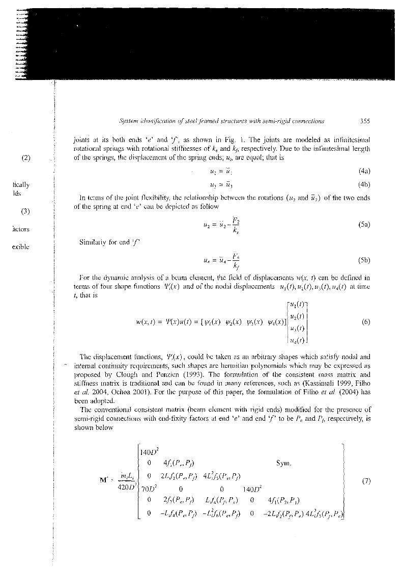
Consider a beam of lcngth LA, nlon~ent of inertia Ib, and mass per unit lerlgth m with flexible
-. - rn i
Eb , Ib= constant
(a) Mc~nbcr forccs for a bca111 clcmcnt with sc~ui-ligid connections
y I
I I
,' Deflected Shape
Infinitesimal Length
(I,) Melnbe~ displaccmenls foi a bcrun elernenl w ~ l h scn~i-ngld coliliecllolis
Fig. 1 ModcItng or a beam element wlth seo11-rigrd coliliectlolis
U l l :ul I I
join rota of tl
I 1 ., Initial Shape k f
I
?'hc inten. propc stiff11 ct al. been
'Ibc
1 7 -- X m l
I
I Lb ;- '\ -1 4------ - - ----
I I
1 Systern ~i ie t~ t~i j i rc~t lo~ c f s t ~ e l jrxrned strz~ctl~rcr. with semi-rigld conncjirtiorls 3 5 5 i I
joints at its both cnds 'c' and ' f , as shown in Fig. 1. The joints are nlodelecl as ~ n f ~ n ~ t c s ~ n l a l I
rotatio~lal sprlngs with rot;ltiotial stiffilesses of ke and kcb respectively. Due to the ~nlinitesimal length
(2) ! of the spnngs, the displacement of the spring euds, 74, are eclual; that is
I - u, = U , (4 a)
I - tic;rlly ; t l j = t l 3 (4b) Ids i
i I
In terms of Lhe joint flexibility, the relationsllil> between the rotations ( z r , and i?,) of the two ends
1 i For the dynalnic analysis of a beam element, the field of displacernents w(,u, t) car1 be defined in
j terms of four shape firnctions 'i((x) and of the nodal displncen~ents 7l,(t), tr2(t), t/,(t), 7i4(1) ilt t i~nc
! t, that is I ru1(t>1
i i I
The displacanent f~:nctions, ?(x), could be taken as an arbitrary shapes which satisfy nodal and 1 - internal continuity rcquirclnents, such shapes are herrr~itia~l polynomials which nlay be cxpcssetl as I
proposect by Clough nnci I'enzicn (1993). The formulation of the consistent mass matrix and I stiffness matrix is traditio~lal and can bc fou~ld in many references, such as (Kassinlali 1999, Filho ! et ul. 2004, Ochoa 2001). For the purpose of this paper, the formulation of Filho et al. (2004) has 1
I been adopted.
1 The conventional consisteut matrix (beam ele~nerlt with rigid ends) nlodified for the presence of semi-rigid con~iections with end-fixity factors at end 'e' and end 'f' to be Pe and T'' respectively, is
j sliown below
S ym.
1f~lsc11.r N Kofkh~ldu, 1iazit11 M Mwari,l and Naslnl ,T/z~lfar.ut
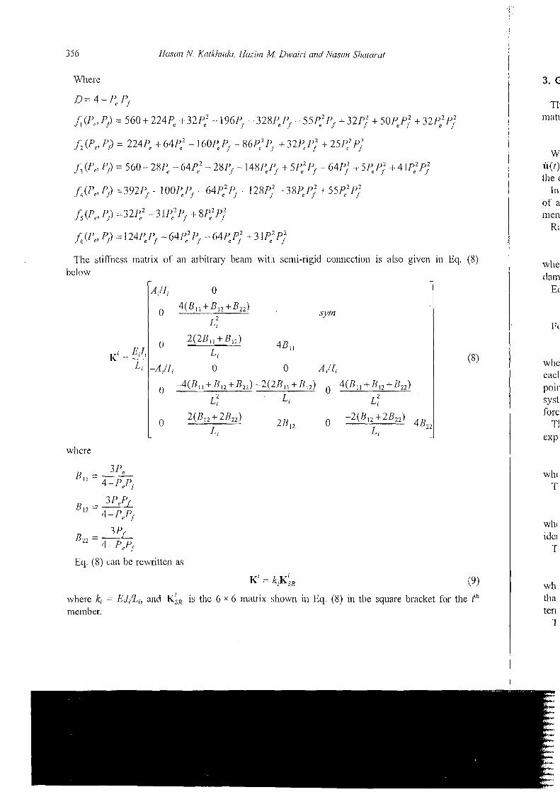
Thc stifSncss matrix oP an arbitraiy beam with semi-rigid connectinn is also given below
0
4 ( B , I +'?I, +B22) .sym
in Eq. (8 )
Eq. ( 8 ) cat1 be rewritten as
W u ( r ) the
In of a Illell
K:
whc e acl poi1 syst
K' = k ' ~ ; ,
wherc ki = LiIiILi, and K:., is the 6 x 6 matrix shown in Eq. ( 8 ) in the square bracket for the iLh
member.
(9)
the ith
I System identijicafion of sleel framed structures with semi-rigid connec-fion.7
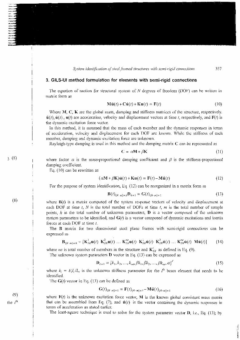
I 3. GILS-UI method formulation for elements with semi-rigid connections
The ecluation of motion for structi~ral system of N degrees of freedom (TIOF) can be written in rnatrix fonn as
Where M, C, K are the global mass, damping and stifliless matrices of the stl-uctt~re, respectively. ii(l), ii(t) , u(t) are acceleration, velocity ant1 displacement vectors at tirnc t, respectively, and Ip(t) is the dynamic excitation force vector.
In this method, it is assunled that the mass o l each member and the dynamic responses in terms of acceleration, velocity and displacement for each DOT: are known. While the stilfness of each mernber, damping and dynarnic excitation force are unlcnown.
Itayleigh-type damping is used in this method and the damping matrix C can he represented as
where factor a is the mass-proportional damping coeflicient and is the stiffness-proportional damping coefficient.
139. (10) can be rewritten as
1 For the 1)i~rpose of system identification, Eel. (12) call be reorganized in a matrix form as
where J3(t) is a matrix cornposed of the system response vectors of velocity and displacement at each DOIT at time t, N is thc total number of DOPs at time t, rn is the total number of sample points, h is the total number of' unl<nown para~neters, D is n vector composed of the unknown system parameters to be identiiied, and C;(t) is a vector composetl of dyilanlic excitations ant1 inertia forces at each DOT; at time t.
The I3 inatrix for two dimensional steel plane frames with semi-rigid contiections can be exprcsscd iis
where rle is total nlumber of n~embcrs in the structure anti K;, as defined in Eel. (9). The unknown system pararlleters D vector in Eq. (13) can be expressed as
where k, = Eil, /I,, is the unknown stiffness parameter for the it" beam elenlent that needs to be identified.
Tlne G(t) vector in Eq. (13) can he defined as
where F(t) is the unknown excitation force vector, M is the known global consistent Inass matrix that can be assembled from Eq. (7), ancl ii(t) is the vector containing the dynarnic rcs],o~lses ill tenns of acceleration as stated earlier.
The least-square technique is used to solve for the system parameter vector D, i.e., Eq. (13); by
I
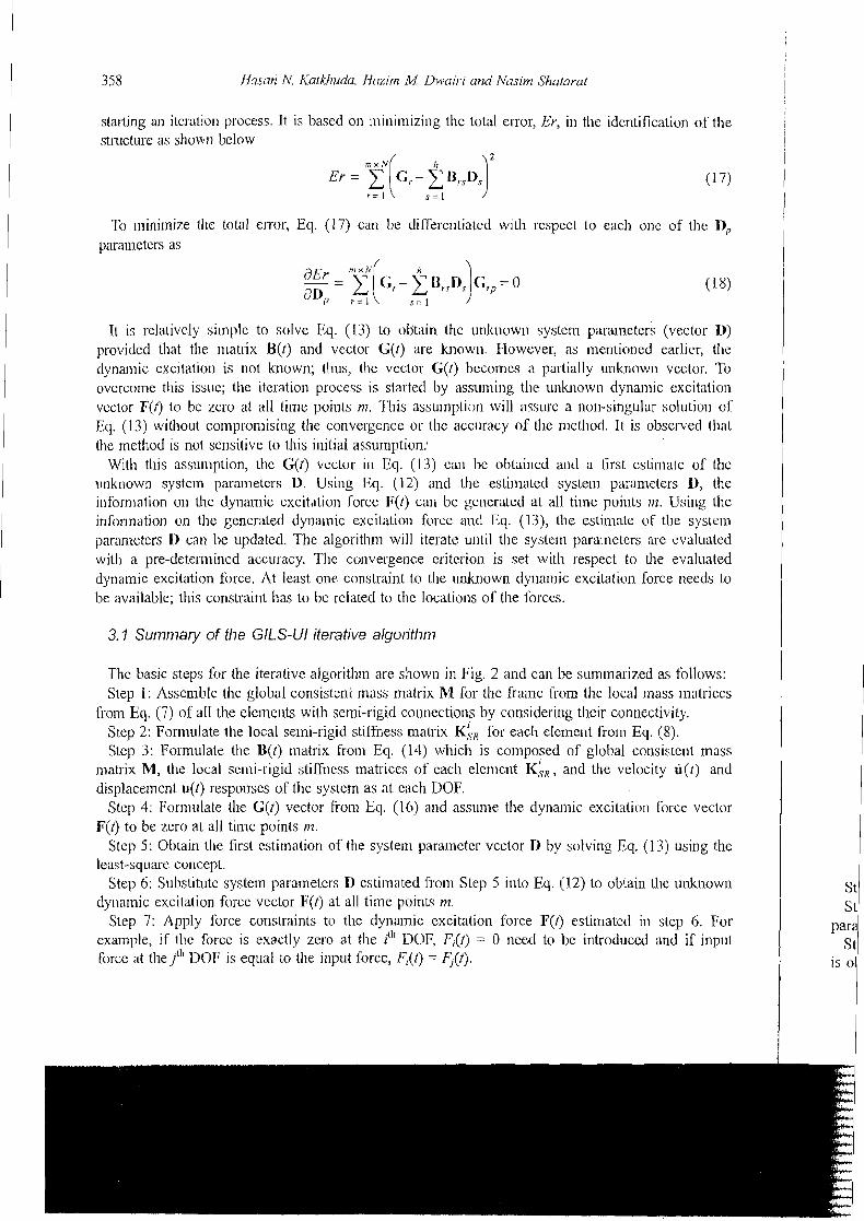
358 /Jc~.san N Katkliudu, i fuzirn Ad Dwrril-I and Nrrsin7 Shatarat I starting an ite~.ation proccss. It is based on minimizing the total error, Er, in the identification of the struciure as show13 below
'Ii, ~ninilnize t l~c total error, Eq. (17) can be differe~~tiatcd with rcspecl to each one of the D, I.~araulletcrs as
It is relatively si~nplc to solve Eq. (13) to obtain the unknown system parameters (vector 11) provided that the ~r~atsix B(t) and vector G(t) are known. I-lowever, as ~nentioncd earlier, the rlynanlic excitatioi~ is not known; tllus, tlie vector G(I) becomes a partially unknown vector. To overcome this issuc; thc iteration process is startetl by assuming the ullluiown dynaliiic excitation vector F(t) lo be zero at all tirne points 177. This assu~nption will assusc a non-singular solution of Iiq. (13) without comproli~ising the convergence or lhc accuracy of the nlctliod. It is obsclved that the method is not sensitive to this initial assurription;
With this assu~nption, the G(t) vector ill Eq. (1.3) call be obtaincd and a Grst estinia(.e of the unknown systcln para~~neters D. Using Eq. (12) and the estiniatcd system parameters D, the i~lfornlation on the dy~iamic excitation force F(t) call be generated at all time points 111. Using tlie infonnatjon on Lhe gcncrated dyna~nic excitatioii forcc and Eq. (13), the estiniatc or the system paranwtcrs 1) can be updated. The algorithm will iterate until t11e systc~n parameters are evaluated with a pre-deterinincd accuracy. The convergence criterion is set with respect to the evaluated dynainic excitation force. At least one cor~slraint to the unknown dyl~ali~ic excilation force needs to be available; this constraint has to bc related to the locatio~is of the forces.
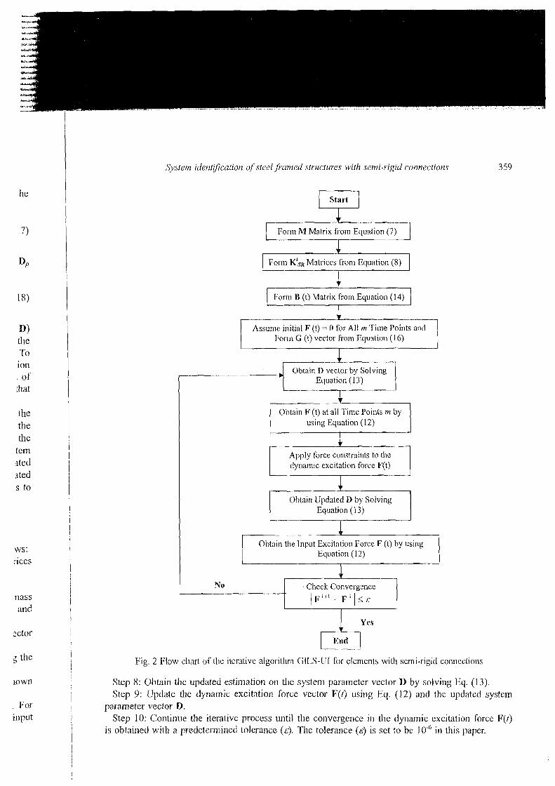
3.1 Summary of the GILS-UI iterative alyoritl~/n
The basic steps for the iterative algoritll~n are shown in Fig. 2 and call be summarized as follows: Step 1: Asscmble the global consisteni mass matrix M for the frame from the local Inass matrices
froin Eq. (7) of all the eleiilelits with semi-rigid connections by consideri~~g their connectivity. Step 2: Forrnulate Ihe local semi-rigid stii'fness matrix K:., for each elcrnc~~t from Eq. (8). Step 3: For~llulate the U(t) 111atrix from Eq. (14) which is co~nposed of global consistelit mass
matrix M, the local semi-rigid stil'fncss matriccs of each elcmcrit K$, , and the velocity u(t) and displacement u(l) responses of the system as at each DOF.
Step 4: Formulate the C(t) vector fi-on1 Eq. (16) and assume the dynamic excitation force vector F(t) to be z,ero at all tiir~e points rrz.
Step 5: Obtain the first estimation of the system pararnetcr vcclor D by solving Eq. (1 3) using the least-square concept.
Step 6: Substitute system parameters D csti~nated foiii Step 5 into Eq. (12) to obtain tlie unk~~own dy~iarnic excitation force vector F(I) at all time points m.
Step 7: Apply force constraints to tlie dynamic excitation lorce F(t) estimated in step 6. For example, if {lie forcc is exactly zcro at the ith DOF, I;;(t) = 0 need to be introduced and if input force at thejih DOE; is equal to the illput forcc, F;(l) = F,(t).
St St
para St
is 01
n> Llie -r0 ion
I of ihat
the the the tem ited s ted s to
ws: ;ices
nass arid
actor
5 the
, For i11p~t
Start L - 4 + Fo1.m hl Matrix from Equaliori (7)
I I
-C Forrn K'SR Matrices from Equation (8)
I + I:ornl B (t) Matrix from Equation (14) .-
initial F (t) = 0 for All m Time Points For~n C (t) vector fi-o~n Equation (1 6)
Obtain D vector by Solving Ecluation (13)
using Equation (12)
I Apply force constrairlts to the dynamic excitation force F(t) I
Equation ( 1 3) 1 C
lnpul Excitfitiorl Force F (t) hy Equation (1 2)
t Check Convergence
Fig. 2 Flow chart of the iterative algorithm CiILS-UI for elements with serni-rigid conneclio~~s
Step 8: Obtain the updated estimation on the system parameter vector D by solving Eq. (13). Step 9: lJpdate the dynamic excitation force vector F(t) using Eq. (12) and the upditted system
parameter vector D. Step 10: Continue the iterative process until the convergence in the dyilamic excilation force F(/)
is obtained with a predetern~ined tolerance (8). The tolerance (E) is set to be 10.' in this paper.

4. Numerical studies
N ~ n e nu~ncrical cxamples are presetltetl in this section to dcmonstrate the applicability, and assess the effectiveness of the proposed SI algorithm. In these examplcs the structural parameters were identified and damages were detected for two-Ji~ncnsional stcel fia~ned buildings with scmi-rig~d ~onnections. A one-bay semi-rigid frame (dcnoted as 1R) as sl~own in Fig. 3 and a two-bay semi- rigid frame (denotcd as 2IJ) as shown in Fig. 4 were uscd in these examples. 111 the 1l3 fi-anle the connections of the bca~n to the columns are assumcd to be scmi-rigid. The end-fixity factor P Tor the bca~n ( i t . , nlcnlber 3) at node 1 and node 2 are assuincd to be 0.20 aud 0.40, respectively as sllown in Fig. 3. W14 >: 53 steel sections are used for all the meinbcrs. ?7le nlasscs of tllc bcain and colu~nns arc assumed to be lu~owrl and are cqual to 696 kg and 271 kg, respectively. The stifliless of the beam and columns (k - EI/L), are calculated to bc 4,924 kN/m atltl 12,3 11 kN/in, respectively.
In thc 2B frame all the conncctions are assu~ncd to be semi-rrgid whcrc the c11d fixity factor 1' for each connectio~l is sllown in Fig. 4. W18 x 71 stcel sections are used for all the meinbers. The masses of each beam and column are assurncd to be known and are cqual to 932 kg aud 362.5 kg, respectively. The beam and colunln stiffi~esses (k = EIIL) are calculated to bc 10,650 kN/nl ant1 26,625 kN/nl, respectively.
?hrce cases were considered for each Trame, nanlcly, 110 dailiage (dcnoted NU), damagc one (denotcd Dl), and damage two (denotcd D2). Damage one (Dl) was rescnlbled in the 1B frame by a 10% reduction 111 the stiffi~ess o l thc beam; whereas in the 2I1, frainc it was rcsc~nbled by a 10% reduction in the stifflless of the second beam, i.e., mcmbcr 2, and 25% stiffness reductio~i in the third coluinn, i.e., ineinber 5. Damagc two (D2) was resenlbled in the 1B frainc by a 20% rcduct~on in the st~ffiless of the beam; whercas in the 2H kame it was resembled by a 20% reduction in tlic stilfncss of the sccond beam, i.e., inember 2, and 50% st~ffness reduct1011 in thc tllird column, i.c.,
Fig. 3 Structural details of one-bay fraiiie (1 B)
F (t) = 0.25 P = 0.25 P = 0.25 P = 0.25 -
1 P = 0.33 TP = 0.33 ' j v = 0.33 f
Fig. 4 Structural details of two-hay frame (2B)
System i~ler2tijiculi01.1 O ~ S ~ C C I j n ~ l e d . S ~ Y Z I C ~ U Y C S iuilll .semi-vigid conrlections
:sess Nere rigid erni- : the r the ow11 ancl
ss of i.
for The
j kg, ancl
one Le by 10% I thc ction n the , ~ . e . ,
0.00 0.10 0.00 0.50 1 .OO t (sec) t (see)
(:I) Triangular i~npact loading (b) I4anno1lic loading
Time (sec)
(c) Vic,lorin eartliquake, Mexico 1980
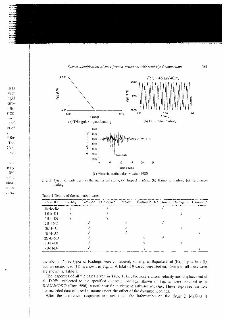
Fig. 5 L)yrramic loads used in the numerical study, (a) l~npact loading, (b) IIamonic loailing, (c) Earihquakc loading
Tdle 1 Deta~ls of the nulner~cal cases - -- -- -- ---
Case ID One-bay Two-bay Earthquake Impact llar~non~c No dainage L)amage I Damage 2 -- ---a- -
1U-E-ND 4 4 d 1 B-E-D 1 d 4 d 1 R-E-D2 4 4 4 2B-I-NL) \I 4 4 213-I-Dl 4 d d 213-I-D2 4 4 d
2B 11-ND 4 4 4 2H-k1-I) I 4 4 4
- 2R-11-D2 - 4 J 4 --
I I member 5. l'hree types of loadings were considered, namely, earthquake load (E), in~pacl. load (I), I and liannonic load (H) as show11 in Fig. 5. A total of 9 cases were studied; details of all these cases ? are shown in Table 1 .
The responses of all the cases given in Table 1 , i.e., the acceleration, velocity and displacement of' all DOFs, sub.jected to the specilied dynamic loadings, shown in Fig. 5, were obtained using
I RAUAMOKO (Carr 1996), a nonlinear finite element software package. These responses resemble the recorded data of a real st]-ucture under the effect of the dynamic loadings.
After the theoretical responses are evaluated, the information on the dynaitlic loatli~lgs is 1
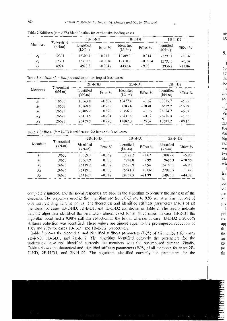
Table 2 Stiffness (k = EllL) iilentificatiou for eaithquake loading cascs
IB-B-ND .. --.
li3;1:-~1 - 1B-E-D2 Tllcoretical - -
Mcn>bers (kN1m) Identified Enor % Identified Identified (JsNl~n) (kN/n~) Effec,t YO (kN/,,l) Efrcct O/b
- -
k , 12311 12309.4 -0.013 12309.3 --0.014 12291.1 -0.16
Table 3 Stifrncss (k = EIIL) identification for impact load cases -- -~ -
2B-I-ND 2U-I-Dl 2U-J-D2 Tlieoretical ----
M e n ~ hers (m-m) Idcntilied E~~~~ % Idcr~tifietl Bfl'ect % Identified (kN-m) (kN-m) (kN-m) Efilcct O/o
-~ -- k, 10650 10563.8 -0.809 10477.4 -1.62 10015.7 -5.95 /c2 10050 10568.8 -0.762 9583.6 - 10.01 8852.7 -16.87 k3 26625 26405.2 --0.826 26156.3 -1.76 24874.7 -6.57
Table 4 Stiflness (/c = EllL,) identificat~on Tor 11al.rnonic: load cascs - - --
---A
2D-11-ND 2U-H-D 1 2B-11-D2 Theoretical ----
Mc~nbcrs (kN-ln) Identified En.or % Identified ~ r f ~ ~ ~ % Identified ~ f f ~ ~ ~ ~ / o (kN-19) (kN-m) (IcN-n~)
complelely ignored, and the nodal responses are used in tlie algorith~n to ide~~tify the stiffi~ess of Ihc elements. Tlie respoliscs used in the algorithm are from 0.02 sec to 0.83 scc at a time interval of 0.01 sec, yielding 52 time points. The theoretical and identified sliffilcss parameters (EI/L) of all members fur cascs IB-E-ND, IU-E-Dl, and II3-E-D2 are shown in Table 2. The results ii~dicate that tlic algorilhnl identified the parameters almost cxact for all three cases. In case IB-E-Dl the algoritlun identified a 9.98% stiffness rcduclion in the beain, whereas in case IB-E-D2 a 20.06% stiffness reduction was identified. These values are allnost equal to the pre-imposed reduction of 10% and 20% for cases IS-E-Dl and 1B-E-D2, respectively.
Tablc 3 shows the theoretical and ideulified stiff~~ess parameters (EI/I,) of all members for cases 2B-I-ND, 2B-I-Dl, and 2B-I-D2. The algoritlun identified correctly the parameters for the undamaged case and identified correctly the tne~nbers with the pre-imposed damagc. Finally, Table 4 shows the theuretical and idcnlified stilfness parameters (El//,) of all ~nembcrs for cases 2B- H-NL), 213-I{-Dl, and 2B-H-D2. The algoritlim identified co~rectly the parameters for the
P O
f
fia Vic of 2U tll€ d a ~ ale ear we twl bl a wh
1 fr a as acc COI
net knl
Prc 1
Pr( res
an. (2( tw tllf
of tlle val of of all
ldicate > I the 0.06$/, ion of
cases or the ;inally, es 2R- 3r the
System idet7tification ofstc!cljPnn?ed stsuctzlre.7 with semi-rigid co17nections
undamaged case and identified correctly the nlelnbers with the pre-imposed damage. In case 2B-H- 112, the pre-imposed damage was identified in member 2 and members 5.
5. Disscussion
For tlie cases studied in this paper, the OILS-UI method for steel fi.ames with semi-rigid connections identified the stilfi~esses of tlie damage-free members very well wit11 211 error lcss than 1%. The responses usetl in the algorithm were 82 time points, i.e., fi.0111 0.02 to 0.83 scc. Altliough tlie algorithm used a small number of time points, the resl~lts of identification are considcred to be accurate. It has been observed by the authors that the number of sample points does not have nl;ljor impact on the accuracy of tlie identified stifiesses. This can be considered as an advantage since no st of time domain methods available in the literature are very sensitive to the number of sarnple points used, in identification.
All the cases showed clearly that thc tncthod was able to identify the damages pre-imposed in tlie frames. The most accurate identification process was in the 1B frame, which was st~bjccted to Victoria eartlliluake acceleration time-history. 'The results showed that there is a sliffness reduction of 9.98% and 20.06%, respectively in the bean and 110 damage in the remaining nlemhers. For Ll~e 2B-1 fianie cases; the results showed that the method detected the pre-imposed damages in one of the beallis and coluinns when the damages were relatively small and large. However, in the largely damaged case, i.e., 2B-I-D2, there was a false detection of damages in two members where tlie algorithm identified a stiffness redidion of aImost 6% in member 1 and member 3. As mentioned earlier; the locat io~~ and amount of stifihess reduction werc selected randomly and the damages were simulated tlieorelically. In this case a stiffness reduction of 20% and 50%) wcrc pre-iniposed in two mcmbers and tlie other members were kept damage-f~ee. Usually, in a real case with a major blast load there will be a large damage in some rnernbers and minor in others and that is exactly what the nlgorithm identified.
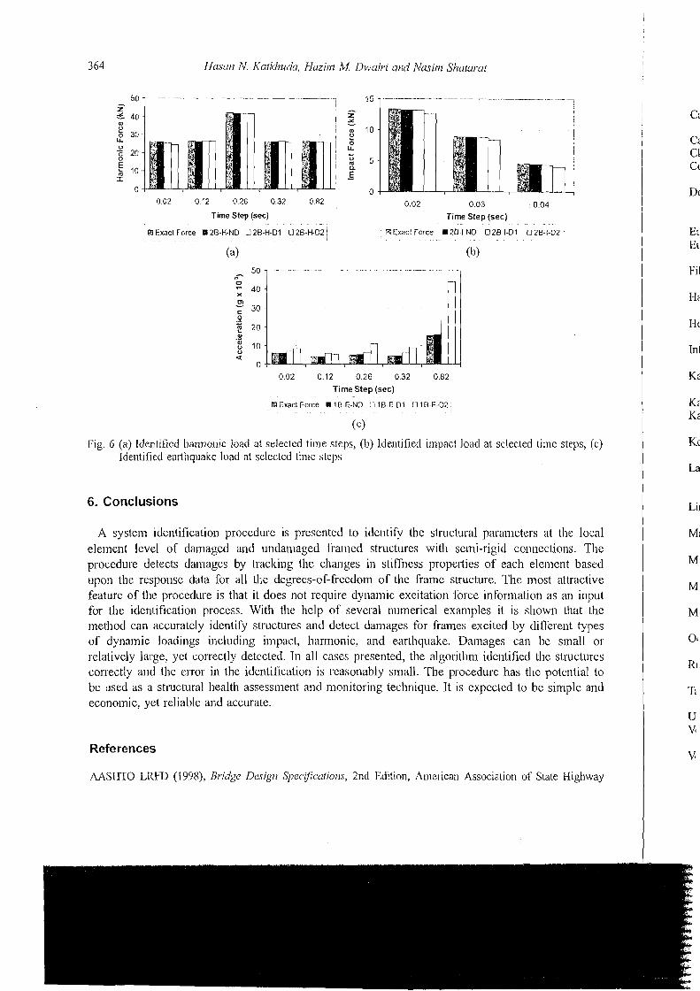
'The results showed that tlie method was able to identify the stiffnesses and detect damages for the frannles that are subjected to different types of loacfng whether earlhqualte, blast or harnionic. Also as a by-product, the method identified [lie i~nknown dyllamic forces subjected to the structures very accurately since it is thc convergetlce criteria used in tlie algorithm as shown in Fig. 6. This can be considered another advantage of the method since most of the methocis available in the literahire need the time-history of the dylialnic force, and for the methods that docs not require a pre- knowledge of the dynamic force, the type of the force is very important in the itlentilicalio~i process.
The responses used for identification in a11 the cases presented are considcred noise-free. Many procedures were proposed by researches in the Ins1 decade to overconle the issue of noise in the responses. For instance, Cooper (2004) proposed a weighted least-square approach that can be applied to a wide range of different time domain syste~n identification algorithms and models. At cliffcrent stages in developing the GlLS-UI lnethod, it was verified theoretically by adding noise in the responses (Wang and Haldar 1994, Ling and Haldar 2004, Katkhuda et 01. 2005) and lately Vo and Haldar (2008) verified the method experimentally on beams, whereas Martinez-Flores et 01. (2006), Martinez-Flores and Haldar (2007), and Haldar et a/. (2008) verified it cxperimentally on a two-dimensional steel frame with rigid connections. The authors decided not to consider noise sirlce the issue of noise is not a problem in the method as veriiied by others.
0 02 0 12 0 26 0 32 0 82 0 02 0 03 0 04 Time Step (sec) Time Step (sec)
Rl Exact Force 111 2B-I4 ND 0 28-H 01 0 20-H 02 13 Exact Force 1 2 6 I-NO O 26-I-Dl 0 2 0 1-02 ,
(a) (b)
0 0 2 0 1 2 0 2 6 032 0 0 2
Time Step (sec)
B Exact Force I 10-E-ND 0 15-E.Dl U 10-E-02
( c )
I:ig. 6 (a) Identified hannunic load at selectecl time steps, (11) lde~ltiiied impact load at selectetl timc steps, (c) Identified earthquakc lvad at selected time steps
6. Conclusions
A system identification procedure is presented to identify the structural parameters at the local element lcvel of damagcd anti undamaged framed structurcs with semi-rigid connections. The procedure dctects damages by tracking t l ~ e changes in stiffness propeltics of each elcmcnt based upon the response data for all the degrees-of-freedom of the frame structure. The most attractive feature of the procedure is that it does not require dynamic excitation force infornlatioll as an input for the identification process. With the hclp of several numerical exiiniples it is shown that the rnelhod can accurately idcntify stix~ctures and dclect damages for frames excited by clifrerellt types of dynamic loadings irlcludillg impact, liarrnonic, aiid earlhqualte. Damages can be sinall or relalivcly large, yet correctly detected. In all cases presented, the algorithm idcntificd thc structures correctly a~ ld the ciror in the identilication is rcasonably small. The p~ocedure has thc potential to be used as a stlxctural health assessnlent and monitoring technique. It is expccted to bc siinplc and economic, yet reliable and accurate.
References
MSIITO LI<f;D (1998), Bridge Dcsign Sl~l,ec.$calions, 2nd Edition, Ame~ican Association of Statc Highway
e local s. 'The
based .ractive n input tlal the t types 11311 or uctures ntial to de a r ~ d
1 ighway
Sy.stem identr>cution oJstecl framed str~~cttrres wit11 sc~n-li-rigid connectiorzs 365
and Transpo~-tation Officials, Washington, USA. Cabrero, J. and Bayo, E. (2005), "Developnlent of practical design methods for steel stri~cti~res witl.1 semi-rigid
connections", E I I ~ . Struct., 27, 1 125- 1 137. Cal-r, A. (1996), RUAUMOICO Uscrs Monziul, University o r Cantelbury, Cluistchurcli, New Zealand. Clough, R.W. and Penzien, J. (1993), Dynumic.r oJStructuue,r, 2nd Edition, McGraw-fIill, Inc. Cooper, J . (2004), "On the llse of weighted least squares for t i~ne doinair1 niodal paramcter idenlificatio~l", Shocsk
ViO., 11, 457-465. Doel~ling, S.W., Fanar, C.R., IJrime, M.B. and Shevitz, U.W. (1996), "Damage identification ant1 heal111
monitoring of struct~lral and mechanical systerns from changes in thcir variation characteristics: A 1,itcrature rcview", L,os Alamos National Laboratory, LA- 130770-MS.
Eurocode 3 (2003), Design of stecl strilckn.es, Part 1-8: Design of joints, (BS EN 1993- I-X:2003). Eurocode 8 (1908), Design of struchlres for earthquake resistance, Part 1 : General rules seismic actions and ri11es
for buildings, (BS EN 1998- 1 ) . Filho, M., Ciuimaraes, M., Sal~lit, C. and Brito, J. (2004), "Wi~ld pressures in framed structures with semi-rigid
connectio~ls", J. B~.azilitriz Soc. hlech. Sci Eng., 26(2), 180-1 89. IIaldar, A., Martinez-Flores, R. and Katkhuda, lI. (2008), "Crack detection in cxisting structures using noise-
contaminated dynamic responses", Theoi: Appl. fiuct. Mcc., 50, 74-80. IJousner, G., 13ergman, L., Caughey, T., Chassiakos, A., Claus, R., Masri, S., Skelton, R., Soong, T., Spencer, 13.
and Yao, J. (1997), "Structural control: Past, present and future", J. Ens. Mech-ASCE, 123(0), 807-071. International Building Code (IBC) (2000), Section 1615: Ea~lhquake loatls, site ground motion, International
Code Council Inc 2000, Falls Church, USA. Kanwar, V., Kwatra, N. and Aggarwal, P. (2007), "Damage detection for framed RCC buildings using ANN
modeling", Int. J Duinoge ~Wech., 16,457-472. Kassimali, A. (1 999), Mutrin Annlyris o f Structures, Brool<s/Cole, USA. Katlhuda, ti., Flores, R.M. and Haldar, A. (2005): "Health assessment at local level with uiknown i~lpul
excitation", J. Sfruct. Eng-ASCE, 131(6), 956-965. Koh, C., Tee, K, and Quek, S. (2006), "Condensed model identification and recovery for structural da~nage
assessment", J S/ru~:t. Ens-ASCE, 132(I 2), 20 18-2026. Lam, 1-I.F., Katafygiotis, S. and Mickleborough, N.C. (2004), "Application of a statistical modcl updating
approach on I'hase I of the IASC-ASCE stluctural health monitoring benchmark study", J. Erg. IIfecIz-ASCE, 130(1), 34-48.
Ling, X. and I-[aldar, A. (2004), "Element level systeni identificalion with uilknown input with rayleigll danlping", ./. Ens. Mech-,4,T%E, 130(8), 877-885.
Ma, T., Yang, f I. and Chang, C. (2005), "Stnlctural damage diagnosis and assessment undcr seismic excitations", J. E'ng. Meclz-ASCE, 13L(LO), 1036-1045.
Martinez-Flores, R. and I-Ialdar, A. (2007), "Experimental veritication of a striicturnl health assessment method without excitation information", J. Strtrct. Erig., 34(1), 33-39.
Martinez-Flores, R., Haldar, A. and ICatl<huda, 11. (2006), "Slri~clural health assessment a h all inlpact", American Society of Mechanical Engineering, IMECE 2006-1 37 18.
Monforton, G.R. and W11, T.S. (1963), "Matrix analysis of semi-rigidly connected stecl frames", J. Strzrcr. Div. A,CCB, 112, 13-42.
Oclloa, J. (2001), "Stabilily and second-order analysis of frames with semi-rigid connections untler distributed axial loads", .I. Struct. Gig-ASCE, 127(1 l), 1306-13 15.
Rutherford, A,, Inman, D., Park, Ci. and tlemez, F. (2005), "Use of response surface rnctamodels l'or identification ol'stilli~ess and damping coefficients in a sin~ple dynamic systc~n", Sl~ock Vih., 12, 317-33 1.
Ta, M., I,ardies, J. and Marc, B. (2006), "Natural frequencies and modal damping ratios identification of civil sti-uctures from ambient vibration data", Shock Vih., 13, 429-444.
Uniform Building Code 2 (1997), Sl~uctural Er~gineerirrg Design Provi.sions, Cengage Learning. Vestroni, F. and Capecchi, D. (2000), "Damage detection in beam struclures based on frequency nieasurements",
J. Eng. Mech-ASCE, 126(7), 761 -768. Vo, P. and Ilaldar, A. (2008), "Health assessment of beams - experimental verification", Stnrci. Ir!finrtruc/ E.,
4(1), 45-56.
366 Has~rn N. Kufkhuda, lfaziin M Dwuiri and Ntrsini Sliuturat
i Wang, D. a~ i t l Haldal; A. (IY94), "An elernc~it level SI with unknown input infomiadon", J. E17g. Me&. Div.
ASCE, 120(1), 159- 176. IVang, D. ant1 tlaldar, A. (1997), "Systcm identification with limited observations and witllolrt input", J. E12g.
hlech-ASCE, 123(5), 504-5 11. Wong, C., Mak, W. atid Kc), J. (1995), "Systcm and parametric identification of flcxiblc conr~cctions in stccl
framed struclures", Eng, Sfruct., 17(8), 58 1-595. i
Yang, J . and Lit?, S. (2005), "lde~itihcation of parametric variations of skuchrrcs bascd on least squal.cs estimation and aclaplivc trnclting technique", J. B I I ~ . A4ecl.1-ASCE., 131, 290-298.
Ya~ig, J., Pan, S. arul IIuang, 11. (2007), "Ail adaptive extcnded kalman filter for slmchiral dainage icleiltification 11: U~lknown inputs", Struct. Co~itrol I-I[f/i. ~Monit., 14, 497-521.
Yang, I., Lin, S., lluang, 11. and Zliou, L. (2006), "An aclaptive extcnded kalnian filter for slructural darnage identification", 9ruc f . Co~itrcll I-IDh, ~Monil., 13, 849-867.
I
Yang, I., Pan, S. and Lin, S. (2007), "Least-squares with I I I ~ ~ I ~ O W I I excitatiolis fOr damage idetltification of structures", J. Llg. Mech-ASCE, 133(l j, 12-2 1 . i 1
i I A
of 1 ci
It aI ar
I CC I nc I
IIE
! he sir


![Rigid , Semi Rigid & Flexible Ducting - Holyoakeattachments.holyoake.com/products/files/Spiro-Set[1172].pdf · Rigid , Semi Rigid & Flexible Ducting ... Pressure Drop Per Metre Length](https://img.pdfslide.us/doc/110x75/5a9e3c667f8b9a36788d1100/rigid-semi-rigid-flexible-ducting-1172pdfrigid-semi-rigid-flexible-ducting.jpg)