Embed Size (px)
Citation preview

System i and System p
Managing the Hardware Management Console (HMC)
���


System i and System p
Managing the Hardware Management Console (HMC)
���

NoteBefore using this information and the product it supports, read the information in “Notices” onpage 107 and the IBM Systems Safety Information manual, G229-9054.
Twelfth Edition (September 2007)
© Copyright International Business Machines Corporation 2004, 2007.US Government Users Restricted Rights – Use, duplication or disclosure restricted by GSA ADP Schedule Contractwith IBM Corp.
Contents
Safety and environmental notices . . . . . . . . . . . . . . . . . . . . . . . . vii
About this topic . . . . . . . . . . . . . . . . . . . . . . . . . . . . . . . . xi
Managing the Hardware Management Console (HMC) . . . . . . . . . . . . . . . . 1PDF file for Managing the HMC. . . . . . . . . . . . . . . . . . . . . . . . . . . . . 1HMC concepts for managing servers . . . . . . . . . . . . . . . . . . . . . . . . . . . 1
Implementations of HMCs. . . . . . . . . . . . . . . . . . . . . . . . . . . . . . 1HMC user interface . . . . . . . . . . . . . . . . . . . . . . . . . . . . . . . . 3
Navigation area . . . . . . . . . . . . . . . . . . . . . . . . . . . . . . . . 4Contents area . . . . . . . . . . . . . . . . . . . . . . . . . . . . . . . . . 4Menu bar . . . . . . . . . . . . . . . . . . . . . . . . . . . . . . . . . . 4Toolbar . . . . . . . . . . . . . . . . . . . . . . . . . . . . . . . . . . . 5Status bar . . . . . . . . . . . . . . . . . . . . . . . . . . . . . . . . . . 5HMC applications . . . . . . . . . . . . . . . . . . . . . . . . . . . . . . . 5
Tasks and roles . . . . . . . . . . . . . . . . . . . . . . . . . . . . . . . . . 7Definitions of HMC roles . . . . . . . . . . . . . . . . . . . . . . . . . . . . . 7HMC configuration tasks . . . . . . . . . . . . . . . . . . . . . . . . . . . . . 8HMC user management tasks . . . . . . . . . . . . . . . . . . . . . . . . . . . 10
Predefined passwords for hscroot and root user IDs . . . . . . . . . . . . . . . . . . . . . 11HMC network connections . . . . . . . . . . . . . . . . . . . . . . . . . . . . . 12
Types of HMC network connections . . . . . . . . . . . . . . . . . . . . . . . . . 12Private and open networks in the HMC environment . . . . . . . . . . . . . . . . . . . 13HMC as a DHCP server . . . . . . . . . . . . . . . . . . . . . . . . . . . . . 17
Web-based System Manager Remote Client . . . . . . . . . . . . . . . . . . . . . . . . 18Installation requirements for the remote client . . . . . . . . . . . . . . . . . . . . . . 18Remote client comparison . . . . . . . . . . . . . . . . . . . . . . . . . . . . 18System Manager Security . . . . . . . . . . . . . . . . . . . . . . . . . . . . . 19
Back up the HMC at regular intervals . . . . . . . . . . . . . . . . . . . . . . . . . 21Installing the HMC . . . . . . . . . . . . . . . . . . . . . . . . . . . . . . . . . 21
Cabling the HMC . . . . . . . . . . . . . . . . . . . . . . . . . . . . . . . . 22Installing the HMC into a rack . . . . . . . . . . . . . . . . . . . . . . . . . . . 30
Installing the 7310-CR47042-CR4 into a rack . . . . . . . . . . . . . . . . . . . . . 36Installing the external modem into a rack . . . . . . . . . . . . . . . . . . . . . . . 45
Check the power source on the rack . . . . . . . . . . . . . . . . . . . . . . . . 45Install the modem into the modem tray . . . . . . . . . . . . . . . . . . . . . . . 46Install the modem tray into the rack . . . . . . . . . . . . . . . . . . . . . . . . 47Complete the installation . . . . . . . . . . . . . . . . . . . . . . . . . . . . 51
Identifying the Ethernet port defined as eth0 . . . . . . . . . . . . . . . . . . . . . . 53Preparing for HMC configuration . . . . . . . . . . . . . . . . . . . . . . . . . . . 54Configuring the HMC . . . . . . . . . . . . . . . . . . . . . . . . . . . . . . . 57
Configuring the HMC using the fast path through the Guided Setup wizard . . . . . . . . . . . 57Prerequisites . . . . . . . . . . . . . . . . . . . . . . . . . . . . . . . . 57Start the fast path through the Guided Setup wizard . . . . . . . . . . . . . . . . . . 58Start the HMC and passwords . . . . . . . . . . . . . . . . . . . . . . . . . . 58Configuring network settings . . . . . . . . . . . . . . . . . . . . . . . . . . 58Configuring connectivity to your service provider . . . . . . . . . . . . . . . . . . . 58Monitoring your configuration status . . . . . . . . . . . . . . . . . . . . . . . . 59
Configuring the HMC using the Guided Setup wizard . . . . . . . . . . . . . . . . . . . 59Prerequisites . . . . . . . . . . . . . . . . . . . . . . . . . . . . . . . . 59Run the Guided Setup Wizard . . . . . . . . . . . . . . . . . . . . . . . . . . 59After you have completed the Guided Setup Wizard . . . . . . . . . . . . . . . . . . 60Starting the Guided Setup wizard using the HMC interface . . . . . . . . . . . . . . . . 61
Configuring the HMC using the HMC configuration checklist . . . . . . . . . . . . . . . . 62Changing the predefined passwords for hscroot and root user IDs . . . . . . . . . . . . . . 63
© Copyright IBM Corp. 2004, 2007 iii
Configuring network connections . . . . . . . . . . . . . . . . . . . . . . . . . 64Setting identification information . . . . . . . . . . . . . . . . . . . . . . . . . 69Configuring a routing entry as the default gateway . . . . . . . . . . . . . . . . . . . 69Configuring domain name services . . . . . . . . . . . . . . . . . . . . . . . . 70Configuring domain suffixes. . . . . . . . . . . . . . . . . . . . . . . . . . . 70Testing the connection between the HMC and the managed system . . . . . . . . . . . . . 71Postconfiguration steps for the HMC . . . . . . . . . . . . . . . . . . . . . . . . 71
Replacing an HMC . . . . . . . . . . . . . . . . . . . . . . . . . . . . . . . . 71Installing and securing the remote client. . . . . . . . . . . . . . . . . . . . . . . . . . 72
Configuring one HMC as a certificate authority . . . . . . . . . . . . . . . . . . . . . . 73Generating private key ring files for the servers . . . . . . . . . . . . . . . . . . . . . . 73Installing private key ring files on the servers . . . . . . . . . . . . . . . . . . . . . . . 74Distributing the certificate authority’s public key with Web-based System Manager Remote Client for Java WebStart . . . . . . . . . . . . . . . . . . . . . . . . . . . . . . . . . . . . . 74Distributing the certificate authority’s public key with Web-based System Manager Remote Client . . . . . 75Viewing configuration properties . . . . . . . . . . . . . . . . . . . . . . . . . . . 76Configuring HMC object manager security . . . . . . . . . . . . . . . . . . . . . . . . 76Installing the Web-based System Manager Remote Client . . . . . . . . . . . . . . . . . . . 77Uninstalling the Web-based System Manager Remote Client . . . . . . . . . . . . . . . . . . 77Installing the Web-based System Manager Remote Client for Java Web Start . . . . . . . . . . . . . 78Uninstalling the Web-based System Manager Remote Client for Java Web Start . . . . . . . . . . . . 79
Working with the HMC . . . . . . . . . . . . . . . . . . . . . . . . . . . . . . . 79Basic operations . . . . . . . . . . . . . . . . . . . . . . . . . . . . . . . . . 79
Starting the HMC . . . . . . . . . . . . . . . . . . . . . . . . . . . . . . . 79Shutting down, logging off, and disconnecting the HMC . . . . . . . . . . . . . . . . . . 80
Logging off the HMC . . . . . . . . . . . . . . . . . . . . . . . . . . . . . 80Changing the date and time . . . . . . . . . . . . . . . . . . . . . . . . . . . . 80Changing the HMC interface language . . . . . . . . . . . . . . . . . . . . . . . . 81Configuring the HMC keyboard layout . . . . . . . . . . . . . . . . . . . . . . . . 81Viewing recent HMC activity . . . . . . . . . . . . . . . . . . . . . . . . . . . 82
Working with partition profile information . . . . . . . . . . . . . . . . . . . . . . . . 82Backing up partition profile data . . . . . . . . . . . . . . . . . . . . . . . . . . 82Initializing profile data . . . . . . . . . . . . . . . . . . . . . . . . . . . . . 83Restoring profile data . . . . . . . . . . . . . . . . . . . . . . . . . . . . . . 83Removing profile data . . . . . . . . . . . . . . . . . . . . . . . . . . . . . . 84
Collecting and viewing resource utilization data . . . . . . . . . . . . . . . . . . . . . . 84Setting the HMC to collect resource utilization data for managed systems . . . . . . . . . . . . 84Viewing resource utilization data for a managed system . . . . . . . . . . . . . . . . . . 85
Backing up and restoring the HMC . . . . . . . . . . . . . . . . . . . . . . . . . . 85Setting up the network interface as a startup device . . . . . . . . . . . . . . . . . . . . 86Setting up a remote system for HMC installation, backup, or restoration over the network . . . . . . . 87Backing up the entire HMC hard drive to a remote system . . . . . . . . . . . . . . . . . 88Backing up critical HMC data . . . . . . . . . . . . . . . . . . . . . . . . . . . 89Restoring the entire HMC hard drive using the network . . . . . . . . . . . . . . . . . . 90Restoring critical HMC data . . . . . . . . . . . . . . . . . . . . . . . . . . . . 91
Restoring from DVD . . . . . . . . . . . . . . . . . . . . . . . . . . . . . 92Restoring from a remote server . . . . . . . . . . . . . . . . . . . . . . . . . . 92
Scheduling and reviewing HMC backups . . . . . . . . . . . . . . . . . . . . . . . 92Saving HMC upgrade data . . . . . . . . . . . . . . . . . . . . . . . . . . . . 92Reinstalling the HMC machine code . . . . . . . . . . . . . . . . . . . . . . . . . 93
Working with users, roles, and passwords . . . . . . . . . . . . . . . . . . . . . . . . 94Creating an HMC user . . . . . . . . . . . . . . . . . . . . . . . . . . . . . 94Viewing an HMC user description. . . . . . . . . . . . . . . . . . . . . . . . . . 94Copying HMC user information . . . . . . . . . . . . . . . . . . . . . . . . . . 94Deleting an HMC user. . . . . . . . . . . . . . . . . . . . . . . . . . . . . . 94Creating a customized HMC role . . . . . . . . . . . . . . . . . . . . . . . . . . 95Editing HMC user information and roles . . . . . . . . . . . . . . . . . . . . . . . 95Changing HMC user passwords . . . . . . . . . . . . . . . . . . . . . . . . . . 95
Using the HMC remote command line . . . . . . . . . . . . . . . . . . . . . . . . . 95Viewing HMC remote command information . . . . . . . . . . . . . . . . . . . . . . 96Setting up secure script execution between SSH clients and the HMC . . . . . . . . . . . . . . 96
iv System i and System p: Managing the Hardware Management Console (HMC)
Enabling and disabling HMC remote commands . . . . . . . . . . . . . . . . . . . . . 97Troubleshooting HMC setup. . . . . . . . . . . . . . . . . . . . . . . . . . . . . . 97Related information for Capacity on Demand . . . . . . . . . . . . . . . . . . . . . . . 102
Appendix. Accessibility features . . . . . . . . . . . . . . . . . . . . . . . . 105
Notices . . . . . . . . . . . . . . . . . . . . . . . . . . . . . . . . . . . 107Trademarks . . . . . . . . . . . . . . . . . . . . . . . . . . . . . . . . . . . 108Electronic emission notices . . . . . . . . . . . . . . . . . . . . . . . . . . . . . . 109
Class A Notices. . . . . . . . . . . . . . . . . . . . . . . . . . . . . . . . . 109Class B Notices . . . . . . . . . . . . . . . . . . . . . . . . . . . . . . . . . 112
Terms and conditions. . . . . . . . . . . . . . . . . . . . . . . . . . . . . . . . 114
Contents v

vi System i and System p: Managing the Hardware Management Console (HMC)

Safety and environmental notices
Safety notices may be printed throughout this guide:v DANGER notices call attention to a situation that is potentially lethal or extremely hazardous to
people.v CAUTION notices call attention to a situation that is potentially hazardous to people because of some
existing condition.v Attention notices call attention to the possibility of damage to a program, device, system, or data.
World Trade safety information
Several countries require the safety information contained in product publications to be presented in theirnational languages. If this requirement applies to your country, a safety information booklet is includedin the publications package shipped with the product. The booklet contains the safety information inyour national language with references to the U.S. English source. Before using a U.S. English publicationto install, operate, or service this product, you must first become familiar with the related safetyinformation in the booklet. You should also refer to the booklet any time you do not clearly understandany safety information in the U.S. English publications.
Laser safety information
IBM® System i® models and System p® servers can use I/O cards or features that are fiber-optic basedand that utilize lasers or LEDs.
Laser compliance
All lasers are certified in the U.S. to conform to the requirements of DHHS 21 CFR Subchapter J for class1 laser products. Outside the U.S., they are certified to be in compliance with IEC 60825 as a class 1 laserproduct. Consult the label on each part for laser certification numbers and approval information.
CAUTION:This product might contain one or more of the following devices: CD-ROM drive, DVD-ROM drive,DVD-RAM drive, or laser module, which are Class 1 laser products. Note the following information:
v Do not remove the covers. Removing the covers of the laser product could result in exposure tohazardous laser radiation. There are no serviceable parts inside the device.
v Use of the controls or adjustments or performance of procedures other than those specified hereinmight result in hazardous radiation exposure.
(C026)
CAUTION:Data processing environments can contain equipment transmitting on system links with laser modulesthat operate at greater than Class 1 power levels. For this reason, never look into the end of an opticalfiber cable or open receptacle. (C027)
CAUTION:This product contains a Class 1M laser. Do not view directly with optical instruments. (C028)
CAUTION:Some laser products contain an embedded Class 3A or Class 3B laser diode. Note the followinginformation: laser radiation when open. Do not stare into the beam, do not view directly with opticalinstruments, and avoid direct exposure to the beam. (C030)
© Copyright IBM Corp. 2004, 2007 vii

Power and cabling information for NEBS (Network Equipment-Building System)GR-1089-CORE
The following comments apply to the IBM System i models and IBM System p servers that have beendesignated as conforming to NEBS (Network Equipment-Building System) GR-1089-CORE:
The equipment is suitable for installation in the following:v Network telecommunications facilitiesv Locations where the NEC (National Electrical Code) applies
The intrabuilding ports of this equipment are suitable for connection to intrabuilding or unexposedwiring or cabling only. The intrabuilding ports of this equipment must not be metallically connected to theinterfaces that connect to the OSP (outside plant) or its wiring. These interfaces are designed for use asintrabuilding interfaces only (Type 2 or Type 4 ports as described in GR-1089-CORE) and require isolationfrom the exposed OSP cabling. The addition of primary protectors is not sufficient protection to connectthese interfaces metallically to OSP wiring.
Note: All Ethernet cables must be shielded and grounded at both ends.
The ac-powered system does not require the use of an external surge protection device (SPD).
The dc-powered system employs an isolated DC return (DC-I) design. The DC battery return terminalshall not be connected to the chassis or frame ground.
Product recycling and disposal
This unit must be recycled or discarded according to applicable local and national regulations. IBMencourages owners of information technology (IT) equipment to responsibly recycle their equipmentwhen it is no longer needed. IBM offers a variety of product return programs and services in severalcountries to assist equipment owners in recycling their IT products. Information on IBM productrecycling offerings can be found on IBM’s Internet site at http://www.ibm.com/ibm/environment/products/prp.shtml.
Esta unidad debe reciclarse o desecharse de acuerdo con lo establecido en la normativa nacional o localaplicable. IBM recomienda a los propietarios de equipos de tecnología de la información (TI) que reciclenresponsablemente sus equipos cuando éstos ya no les sean útiles. IBM dispone de una serie de programasy servicios de devolución de productos en varios países, a fin de ayudar a los propietarios de equipos areciclar sus productos de TI. Se puede encontrar información sobre las ofertas de reciclado de productosde IBM en el sitio web de IBM http://www.ibm.com/ibm/environment/products/prp.shtml.
Note: This mark applies only to countries within the European Union (EU) and Norway.
Appliances are labeled in accordance with European Directive 2002/96/EC concerning waste electricaland electronic equipment (WEEE). The Directive determines the framework for the return and recyclingof used appliances as applicable throughout the European Union. This label is applied to variousproducts to indicate that the product is not to be thrown away, but rather reclaimed upon end of life perthis Directive.
viii System i and System p: Managing the Hardware Management Console (HMC)

In accordance with the European WEEE Directive, electrical and electronic equipment (EEE) is to becollected separately and to be reused, recycled, or recovered at end of life. Users of EEE with the WEEEmarking per Annex IV of the WEEE Directive, as shown above, must not dispose of end of life EEE asunsorted municipal waste, but use the collection framework available to customers for the return,recycling, and recovery of WEEE. Customer participation is important to minimize any potential effects ofEEE on the environment and human health due to the potential presence of hazardous substances in EEE.For proper collection and treatment, contact your local IBM representative.
Battery return program
This product may contain sealed lead acid, nickel cadmium, nickel metal hydride, lithium, or lithium ionbattery. Consult your user manual or service manual for specific battery information. The battery must berecycled or disposed of properly. Recycling facilities may not be available in your area. For informationon disposal of batteries outside the United States, go to http://www.ibm.com/ibm/environment/products/batteryrecycle.shtml or contact your local waste disposal facility.
In the United States, IBM has established a return process for reuse, recycling, or proper disposal of usedIBM sealed lead acid, nickel cadmium, nickel metal hydride, and other battery packs from IBMEquipment. For information on proper disposal of these batteries, contact IBM at 1-800-426-4333. Pleasehave the IBM part number listed on the battery available prior to your call.
For Taiwan: Please recycle batteries.
For the European Union:
Note: This mark applies only to countries within the European Union (EU).
Batteries or packaging for batteries are labeled in accordance with European Directive 2006/66/ECconcerning batteries and accumulators and waste batteries and accumulators. The Directive determinesthe framework for the return and recycling of used batteries and accumulators as applicable throughoutthe European Union. This label is applied to various batteries to indicate that the battery is not to bethrown away, but rather reclaimed upon end of life per this Directive.
In accordance with the European Directive 2006/66/EC, batteries and accumulators are labeled toindicate that they are to be collected separately and recycled at end of life. The label on the battery mayalso include a chemical symbol for the metal concerned in the battery (Pb for lead, Hg for mercury andCd for cadmium). Users of batteries and accumulators must not dispose of batteries and accumulators asunsorted municipal waste, but use the collection framework available to customers for the return,recycling, and treatment of batteries and accumulators. Customer participation is important to minimizeany potential effects of batteries and accumulators on the environment and human health due to thepotential presence of hazardous substances. For proper collection and treatment, contact your local IBMrepresentative.
Safety and environmental notices ix

For California: Perchlorate Material - special handling may apply. See www.dtsc.ca.gov/hazardouswaste/perchlorate.
The foregoing notice is provided in accordance with California Code of Regulations Title 22, Division 4.5Chapter 33. Best Management Practices for Perchlorate Materials. This product/part may include alithium manganese dioxide battery which contains a perchlorate substance.
IBM Cryptographic Coprocessor Card Return Program
The following information applies only for systems originally sold prior to July 1, 2006:
This machine may contain an optional feature, the cryptographic coprocessor card, which includes apolyurethane material that contains mercury. Please follow local ordinances or regulations for disposal ofthis card. IBM has established a return program for certain IBM Cryptographic Coprocessor Cards. Moreinformation can be found at http://www.ibm.com/ibm/environment/products/prp.shtml.
x System i and System p: Managing the Hardware Management Console (HMC)

About this topic
This topic describes how to manage the Hardware Management Console (HMC). The HMCcommunicates with systems using service applications to detect, consolidate, and send information foranalysis. It is also used to partition the server to which it is connected.
For information about the accessibility features of this product, for users who have a physical disability,see “Accessibility features,” on page 105.
© Copyright IBM Corp. 2004, 2007 xi

xii System i and System p: Managing the Hardware Management Console (HMC)
Managing the Hardware Management Console (HMC)
Understand how to manage your Hardware Management Console.
You can manage your servers, logical partitions, and Capacity on Demand with the HardwareManagement Console (HMC). The HMC communicates with systems using service applications to detect,consolidate, and send information to IBM for analysis.
Attention: To avoid potential problems, if you plan to install an earlier version of your server or theHMC, from one release to an earlier release, contact IBM service and support before you perform anyinstallation procedures of this type.
PDF file for Managing the HMCYou can view and print a PDF file of this information.
To view or download the PDF version of this document, select Managing the Hardware Management
Console (about 1628 KB).
Saving PDF files
To save a PDF on your workstation for viewing or printing:1. Right-click the PDF in your browser (right-click the link above).2. Click the option that saves the PDF locally.3. Navigate to the directory in which you want to save the PDF.4. Click Save.
Downloading Adobe Reader
You need Adobe Reader installed on your system to view or print these PDFs. You can download a free
copy from the Adobe Web site (www.adobe.com/products/acrobat/readstep2.html) .
HMC concepts for managing serversLearn about the concepts that you need to know before you use the HMC to work with managedsystems.
The HMC allows you to perform a variety of tasks associated with managing your servers and frames.This information familiarizes you with the HMC concepts that you should know before working with themanaged systems.
Implementations of HMCsLearn about the local HMC, the remote HMC, and the Web-based System Manager Remote Client.
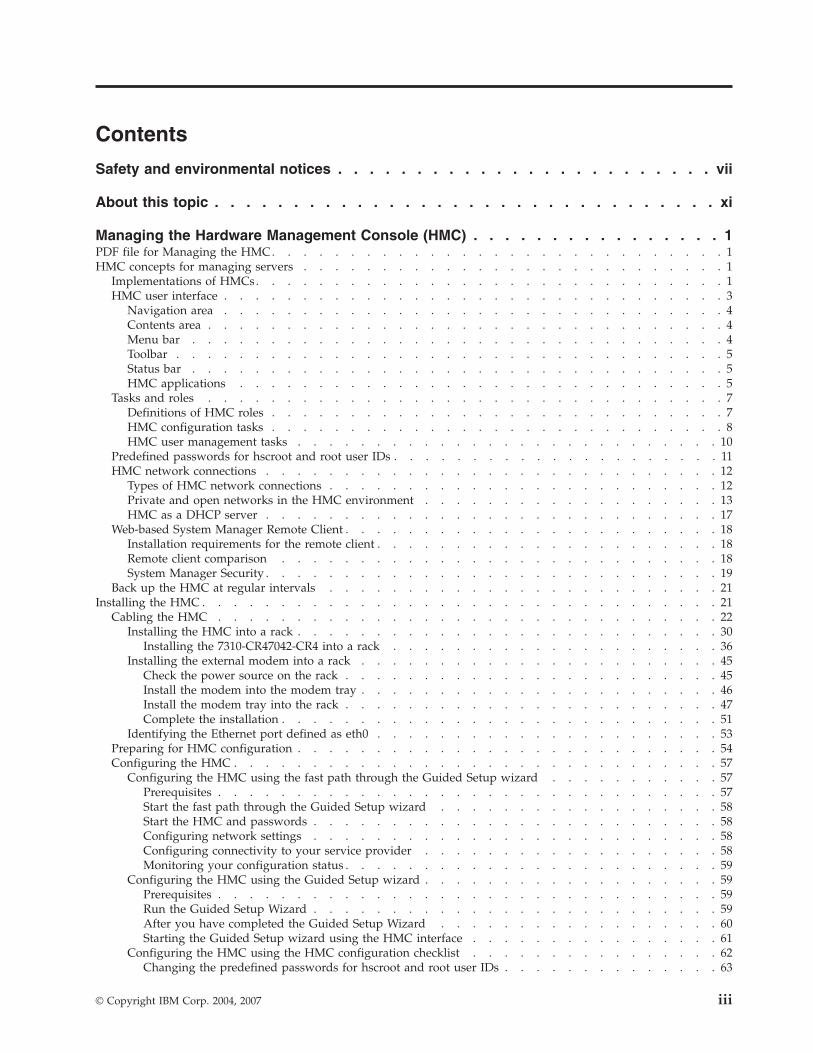
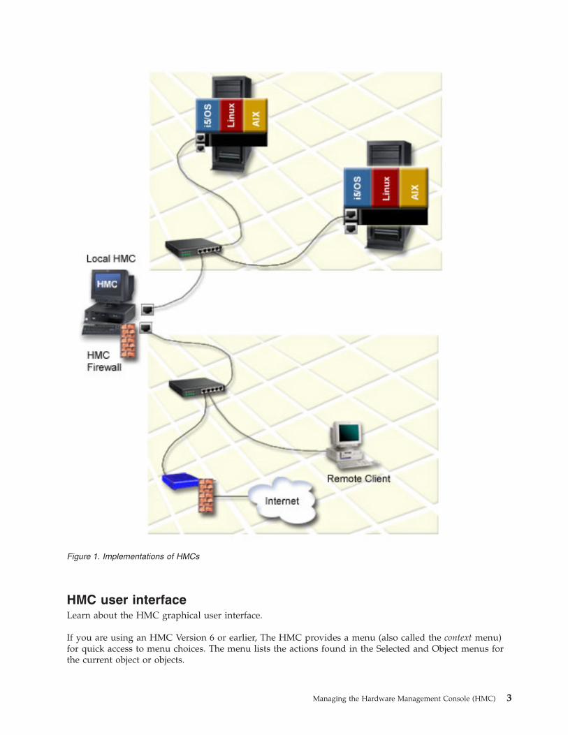
The Hardware Management Console (HMC) is a system that controls managed systems, includinghardware, logical partitions, and Capacity on Demand. To provide flexibility and availability, there aredifferent ways to implement HMCs, including the local HMC, remote HMC, redundant HMC, and theWeb-based System Manager Remote Client. Figure 1 on page 3 illustrates how HMCs might beimplemented in your network.
© Copyright IBM Corp. 2004, 2007 1
Local HMCA local HMC is one that is physically located close to the system it manages and is connected byeither a private or public network. An HMC in a private network is a DHCP server for theservice processors of the systems it manages. An HMC may also manage a system over an opennetwork, where the managed system’s service processor IP address has been assigned manuallyusing the Advanced System Management Interface (ASMI). For convenience of service personnel,an HMC should be close in proximity to the servers it manages.
Remote HMCA remote HMC is one that is network-connected to a distant managed server or HMC.
Redundant HMCA redundant HMC manages a system that is already managed by another HMC. When twoHMCs manage one system, they are peers, and each can be used to control the managed system.One HMC can manage multiple managed systems, and each managed system can have twoHMCs. If both HMCs are connected to the server using private networks, each HMC must be aDHCP server set up to provide IP addresses on two unique, nonroutable IP ranges.
Web-based System Manager Remote ClientThe Web-based System Manager Remote Client is an application that is usually installed on a PC.You can then use this PC to access other HMCs remotely. Web-based System Manager RemoteClients can be present in private and open networks. You can perform most management tasksusing the Web-based System Manager Remote Client.
The remote HMC and the Web-based System Manager Remote Client allow you the flexibility to accessyour managed systems (including HMCs) from multiple locations.
For more information about how you can plan for and implement HMCs, see Solutions with theHardware Management Console (HMC).
2 System i and System p: Managing the Hardware Management Console (HMC)
HMC user interfaceLearn about the HMC graphical user interface.
If you are using an HMC Version 6 or earlier, The HMC provides a menu (also called the context menu)for quick access to menu choices. The menu lists the actions found in the Selected and Object menus forthe current object or objects.
Figure 1. Implementations of HMCs
Managing the Hardware Management Console (HMC) 3

If you are using an HMC Version 7 or later, The user interface provided with the Hardware ManagementConsole (HMC) uses navigation that provides hierarchical views of system resources and tasks. This userinterface is made up of several major components: the Banner, the Navigation pane, the Work pane, theTask bar, and the Status bar. The following sections describe each of these components.
Navigation areaLearn about the navigation area of the HMC GUI.
The left side of the HMC GUI is the Navigation area. It displays a hierarchy of items ordered in a treestructure. The root of the tree is the Management Environment, which contains the name of the HMCinto which you are currently logged. This name is the same as the host name that you have given theHMC.
The Management Environment is a set of host systems that can be managed from the HMC. The hostsystems can be the HMC into which you are currently logged and other remote HMCs.
Each folder in the Navigation area contains different HMC applications used in the specific managementtask, such as the Server and Partition folder. If you select one of these HMC applications, it providesappropriate submenus and objects in the Contents area.
Contents areaLearn about the contents area of the HMC GUI.
The right side of the HMC GUI is called the Contents area. It displays managed objects and related tasks.You can select different views in the Contents area: large icons, small icons, or details in the form of a list.
Menu barUnderstand the menu bar on the HMC GUI.
The following menu items are provided in the menu bar of the HMC GUI:
ConsoleThe Console menu contains choices that control the console. It enables you to add and removemanaged systems, other HMCs, or other systems from the management environment. It alsoenables you to change themes on the desktop, change font sizes, open an outbound Telnetterminal session using an IP address or a host name, and exit the console.
ObjectThe title of the Object menu changes to indicate the type of resource managed by the currentHMC application. For example, when the Server Management application is selected, the Objectmenu title becomes Server Management. The Object menu contains general choices and actionsfor an HMC application that do not require the selection of specific objects to act on. The findfunction is also located in the Object menu. The contents of the Object menu are updated when anew HMC application is selected.
SelectedThe Selected menu contains the set of actions that are applicable to the object selected in theContents pane. The contents of the Selected menu are updated based on which object you select.The Selected menu is disabled when Overview and Launch applications are loaded. The open tabin the Selected menu expands the view of a managed system in the Navigation area.
View The View menu contains choices for navigating. It also includes choices for customizing theconsole in the Show submenu. For example, you can select to show or hide the toolbar and statusbar. This menu also includes options that control how objects are presented. For example, if theContents area content provides a choice of views, such as Large Icon, Small Icon, Details, andTree, these choices are listed here. If the content has only a single view, no view choices are listed.When the content displays an icon or details view, the View menu includes choices for sortingand filtering the container.
4 System i and System p: Managing the Hardware Management Console (HMC)
WindowThe Window menu contains actions for managing subpanels in the console workspace. The newvirtual terminal creates a new console subpanel in the workspace. Other choices control how allconsole subpanels are presented.
Help The Help menu lists user assistance choices. Different options enable you to view help contents,search for help on a particular topic, and view help information about shortcut keys.
ToolbarLearn about the toolbar on the HMC interface.
The toolbar of the HMC GUI lists commonly used actions that are available when the current plug-inapplication is loaded. It includes navigation controls, Find and View choices (if available), and a refreshoption of the HMC GUI. The toolbar also provides tool tip help when the pointer remains over a toolbaricon for a few seconds.
Status barLearn about the status bar on the HMC.
Choose from the following options:v If you are using an HMC Version 6 or earlier, continue with Status bar for an HMC Version 6 or earlier.
Status bar for an HMC Version 6 or earlier
The status bar of the displays at the lower edge of a console panel. It can be hidden or shown by clearingor checking the Status Bar option in the Show submenu under View. The status bar has the followingfields ordered from left to right for displaying status information:
Padlock iconThe padlock icon is open when secure communications are not active.
Application loading statusWhen an HMC application is loaded, the text Ready displays. When an application is in theprocess of loading, a graphical bar is displayed.
Number of objects visible in the Contents areaObjects can be present on the managed system but hidden from the view by the view filter.
Number of objects selected in the Contents areaThis field displays the number of objects that you have selected in the Contents area.
Security contextThis field displays the administrator user name and the HMC host name for the currently activeHMC.
Status bar for an HMC Version 7 or later
The Status bar provides a visual cue for the current overall system status, including managed systemresources and the HMC. Icons, text, and color of the Status bar indicate overall status. Note the following:v If the Status bar is green, there are no exceptions, hardware messages or operating system messages.v When there are resources (such as a managed system or partition) in an exception state, the Status bar
is red, the Exceptions icon appears, and Status: Exceptions is displayed.v When messages are waiting for you to read, the Status bar displays the Hardware Messages and/or
the Operating System messages icons. In addition, Status: Messages is displayed.v The Status Overview icon is always available in the Status bar.
HMC applicationsUnderstand the HMC folders and applications.
Managing the Hardware Management Console (HMC) 5
Application folders and application icons are provided in the Navigation area in the HMC GUI. Thefolders and icons contain several applications to be used for different system management tasks on theHMC and managed systems.
Server and PartitionThe Server and Partition folder contains the Server and Frame Management applications. TheServer Management application provides all logical partition-related tasks. It is used to create,maintain, activate, and delete logical partitions. This application also provides a focal point for allmanaged-system related tasks, such as powering the managed system on and off. The FrameManagement application provides frame Bulk Power Assembly (BPA)-related tasks. It can be usedto update managed frame passwords. This application can also be used to add, initialize, reset,remove, and view properties of managed frames. For more information about logical partitions,see Partitioning the server. For more information about working with the managed system andframe, see Working with managed systems and frames.
System PlansThis folder contains the system plan applications. A system plan is a specification of the logicalpartition configuration of a single managed system. Use the System plans applications to import,deploy, and manage system plans.
For more information about system plans, see \Creating partitions from a system plan.
Licensed Internal Code MaintenanceThe Licensed Internal Code Maintenance application folder contains the HMC Code Update andLicensed Internal Code Updates applications. For more information about using theseapplications to maintain the code on your systems, see Getting fixes.
HMC ManagementThis folder contains the HMC configuration and HMC Users applications. Use the HMCconfiguration application to do the following:v Set the HMC date and time. For more information about setting the HMC date and time, see
“Changing the date and time” on page 80.v Configure and test network settingsFor more information about configuring network settings,
see “Configuring the HMC using the HMC configuration checklist” on page 62.v View console eventsFor more information about viewing console events, see “Viewing recent
HMC activity” on page 82.v Schedule routine backupsFor more information about scheduling backups, see “Backing up and
restoring the HMC” on page 85.v Enable and disable remote commands and virtual terminals.
Use the HMC Users application to manage HMC users. For more information about managingusers, see “Basic operations” on page 79.
Service ApplicationsThis folder contains several applications to be used for service-related tasks. For moreinformation about using these applications, see Customer service and support.
Information Center and Setup WizardThe Information Center and Setup Wizard application allows you to open the technicaldocumentation for your server. The Setup Wizard helps you configure the HMC to work with themanaged system. For more information about configuring the HMC using the Setup Wizard, see“Configuring the HMC using the Guided Setup wizard” on page 59.
Switch ManagementThe Switch Management folder contains applications used to manage switches in clusterenvironment.
6 System i and System p: Managing the Hardware Management Console (HMC)
Tasks and rolesUnderstand the user roles that can be assigned to each HMC user. Learn about the tasks that each HMCuser role can perform and the commands associated with each task.
The following topics provide essential information regarding HMC roles and various configuration anduser management tasks that can be performed:
Definitions of HMC rolesLearn about the user roles that can be assigned to each HMC user. Also, learn about the tasks that eachHMC user role can perform and the commands associated with each task.
Each HMC user can be a member of a different role. Each of these roles allows the user to access differentparts of the HMC and perform different tasks on the managed system. HMC roles are either predefined orcustomized.
The roles discussed in this section refer to HMC users; operating systems running on logical partitionshave their own set of users and roles.
When you create an HMC user, you must assign that user a task role. Each task role allows the uservarying levels of access to tasks available on the HMC interface.
For more information about the tasks each HMC user role can perform and the commands associatedwith each task, see Overview of HMC tasks.
You can assign managed systems and logical partitions to individual HMC users. This allows you tocreate a user that has access to managed system A but not to managed system B. Each grouping ofmanaged resource access is called a managed resource role.
To learn more about managed resource roles and how to create them, refer to the HMC interface help.
Predefined HMC roles
The predefined HMC roles, which are the default on the HMC, are as follows:
Super Administrator (hmcsuperadmin)The super administrator acts as the root user, or manager, of the HMC system. The superadministrator has unrestricted authority to access and modify most of the HMC system.
service representative (hmcservicerep)A service representative is an employee who is at your location to install, configure, or repair thesystem.
operator (hmcoperator)An operator is responsible for daily system operation.
product engineer (hmcpe)A product engineer assists in support situations, but cannot access HMC user managementfunctions. To provide support access for your system, you must create and administer user IDswith the product engineer role.
viewer (hmcviewer)A viewer can view HMC information, but cannot change any configuration information.
Customized HMC roles
You can create customized HMC roles by modifying predefined HMC roles. Creating customized HMCroles is useful for restricting or granting specific task privileges to a certain user.
Managing the Hardware Management Console (HMC) 7
For more information about creating customized HMC roles, see “Creating a customized HMC role” onpage 95.
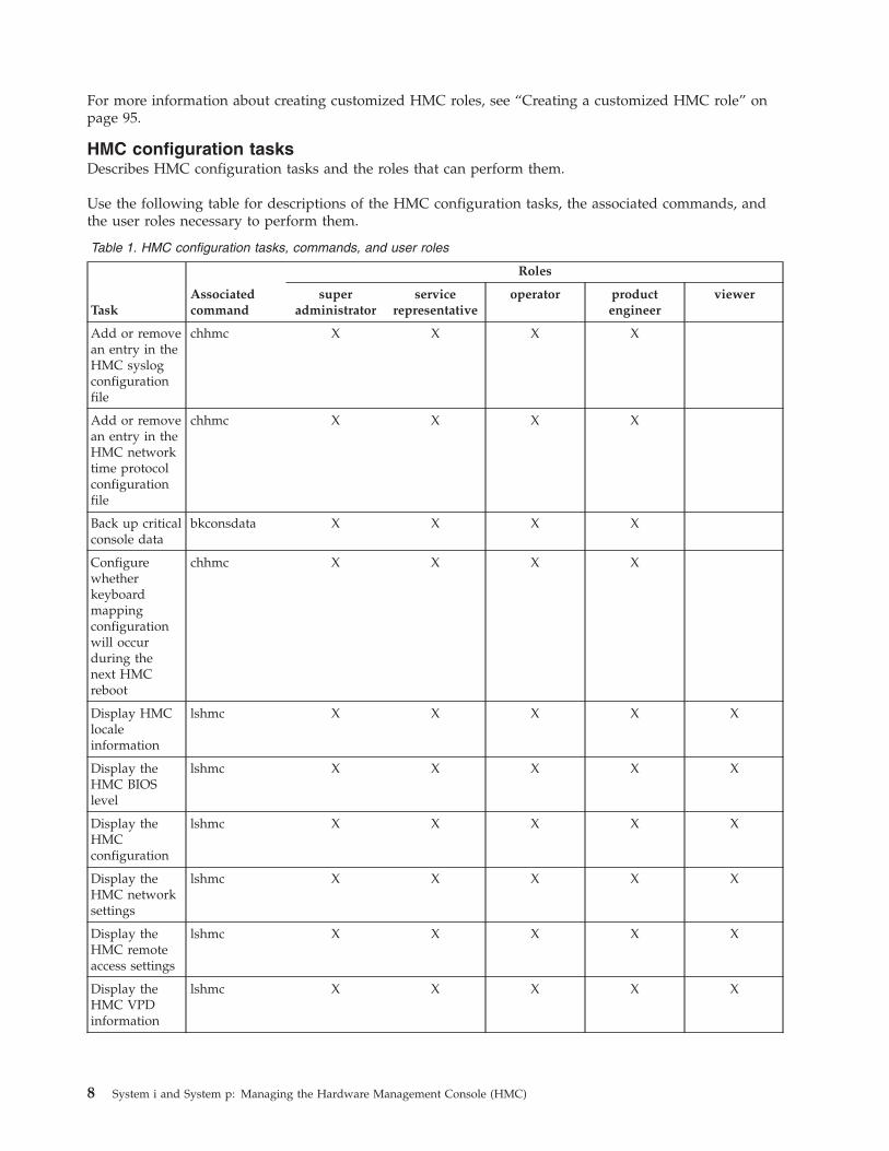
HMC configuration tasksDescribes HMC configuration tasks and the roles that can perform them.
Use the following table for descriptions of the HMC configuration tasks, the associated commands, andthe user roles necessary to perform them.
Table 1. HMC configuration tasks, commands, and user roles
TaskAssociatedcommand
Roles
superadministrator
servicerepresentative
operator productengineer
viewer
Add or removean entry in theHMC syslogconfigurationfile
chhmc X X X X
Add or removean entry in theHMC networktime protocolconfigurationfile
chhmc X X X X
Back up criticalconsole data
bkconsdata X X X X
Configurewhetherkeyboardmappingconfigurationwill occurduring thenext HMCreboot
chhmc X X X X
Display HMClocaleinformation
lshmc X X X X X
Display theHMC BIOSlevel
lshmc X X X X X
Display theHMCconfiguration
lshmc X X X X X
Display theHMC networksettings
lshmc X X X X X
Display theHMC remoteaccess settings
lshmc X X X X X
Display theHMC VPDinformation
lshmc X X X X X
8 System i and System p: Managing the Hardware Management Console (HMC)
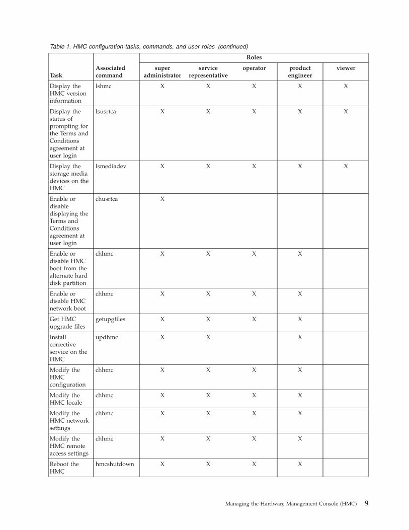
Table 1. HMC configuration tasks, commands, and user roles (continued)
TaskAssociatedcommand
Roles
superadministrator
servicerepresentative
operator productengineer
viewer
Display theHMC versioninformation
lshmc X X X X X
Display thestatus ofprompting forthe Terms andConditionsagreement atuser login
lsusrtca X X X X X
Display thestorage mediadevices on theHMC
lsmediadev X X X X X
Enable ordisabledisplaying theTerms andConditionsagreement atuser login
chusrtca X
Enable ordisable HMCboot from thealternate harddisk partition
chhmc X X X X
Enable ordisable HMCnetwork boot
chhmc X X X X
Get HMCupgrade files
getupgfiles X X X X
Installcorrectiveservice on theHMC
updhmc X X X
Modify theHMCconfiguration
chhmc X X X X
Modify theHMC locale
chhmc X X X X
Modify theHMC networksettings
chhmc X X X X
Modify theHMC remoteaccess settings
chhmc X X X X
Reboot theHMC
hmcshutdown X X X X
Managing the Hardware Management Console (HMC) 9
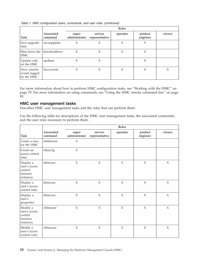
Table 1. HMC configuration tasks, commands, and user roles (continued)
TaskAssociatedcommand
Roles
superadministrator
servicerepresentative
operator productengineer
viewer
Save upgradedata
saveupgdata X X X X
Shut down theHMC
hmcshutdown X X X X
Update codeon the HMC
updhmc X X X
View consoleevents loggedby the HMC
lssvcevents X X X X X
For more information about how to perform HMC configuration tasks, see “Working with the HMC” onpage 79. For more information on using commands, see “Using the HMC remote command line” on page95.
HMC user management tasksDescribes HMC user management tasks and the roles that can perform them.
Use the following table for descriptions of the HMC user management tasks, the associated commands,and the user roles necessary to perform them.
TaskAssociatedcommand
Roles
superadministrator
servicerepresentative
operator productengineer
viewer
Create a userfor the HMC
mkhmcusr X
Create anaccess controlroles
mkaccfg X
Display auser’s accesscontrolresourceinstances
lshmcusr X X X X X
Display auser’s accesscontrol roles
lshmcusr X X X X X
Display auser’sproperties
lshmcusr X X X X X
Modify auser’s accesscontrolresourceinstances
chhmcusr X X X X X
Modify auser’s accesscontrol roles
chhmcusr X X X X X
10 System i and System p: Managing the Hardware Management Console (HMC)
TaskAssociatedcommand
Roles
superadministrator
servicerepresentative
operator productengineer
viewer
Modify auser’spassword
chhmcusr X X X X X
Modify auser’sproperties
chhmcusr X X X X X
Modify anaccess controlrole
chaccfg X
Remove anaccess controlrole.
rmaccfg X
Removeinactive accesscontrolresourceinstancesassigned to auser
rmaccfg X
Remove a userfrom the HMC
rmhmcusr X
View an accesscontrolresourceinstance
lsaccfg X X X X X
View an accesscontrol role
lsaccfg X X X X X
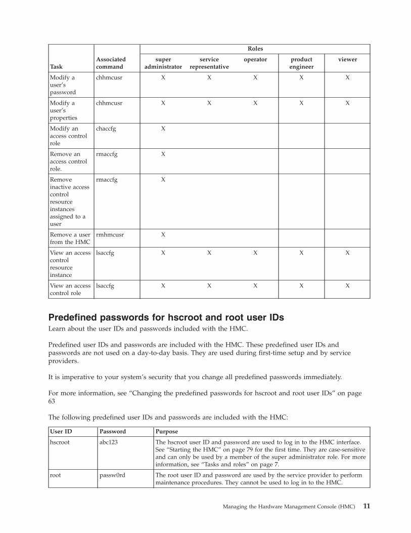
Predefined passwords for hscroot and root user IDsLearn about the user IDs and passwords included with the HMC.
Predefined user IDs and passwords are included with the HMC. These predefined user IDs andpasswords are not used on a day-to-day basis. They are used during first-time setup and by serviceproviders.
It is imperative to your system’s security that you change all predefined passwords immediately.
For more information, see “Changing the predefined passwords for hscroot and root user IDs” on page63
The following predefined user IDs and passwords are included with the HMC:
User ID Password Purpose
hscroot abc123 The hscroot user ID and password are used to log in to the HMC interface.See “Starting the HMC” on page 79 for the first time. They are case-sensitiveand can only be used by a member of the super administrator role. For moreinformation, see “Tasks and roles” on page 7.
root passw0rd The root user ID and password are used by the service provider to performmaintenance procedures. They cannot be used to log in to the HMC.
Managing the Hardware Management Console (HMC) 11
HMC network connectionsLearn how the HMC can be used in a network.
You can use different types of network connections to connect your HMC to managed systems. For moreinformation about configuring the HMC to connect to a network, see “Configuring the HMC using theHMC configuration checklist” on page 62. For more information about using the HMC on a network, seethe following:
Types of HMC network connectionsLearn how to use the HMC remote management and service functions using your network.
The HMC supports the following types of logical communications:
HMC to managed systemThis type of communications is used to perform most of the hardware management functions, inwhich HMC issues control function requests through the service processor of the managedsystem.
HMC to logical partitionThis type of communications is used to collect platform-related information (hardware errorevents, hardware inventory) from the operating systems running in the logical partitions, as wellas to coordinate certain platform activities (dynamic LPAR, concurrent repair) with thoseoperating systems. If you want to use service and error notification features, it is important thatyou make this connection.
HMC to remote usersThis type of communications provides remote users with access to HMC functionality. Remoteusers can access the HMC in the following ways:v By using the remote client (if you are using an HMC Version 6 or earlier) or web browser (if
you are using a an HMC Version 7 or later) to access all the HMC GUI functions remotelyv By using SSH to access the HMC command line functions remotelyv By using a virtual terminal server for remote access to virtual logical partition consoles
HMC to service and supportThis type of communications is used to transmit data, such as hardware error reports, inventorydata, and microcode updates, to and from your service provider. You can use thiscommunications path to make automatic service calls.
The HMC supports up to four separate physical Ethernet interfaces. In the desktop version of the HMC,this consists of one integrated Ethernet and up to two plug-in adapters. In the rack-mounted version, thisconsists of two integrated Ethernet adapters and up to one plug-in adapter. Use each of these interfacesin the following ways:v One network interface can be used exclusively for HMC-to-managed system communications, which
means that only the HMC and service processors of the managed systems would be on that network.Even though the network interfaces into the service processors are encrypted for the Secure SocketsLayer (SSL) protocol and password-protected, having a separate dedicated network can provide ahigher level of security for these interfaces.
v Another network interface would typically be used for the network connection between the HMC andthe logical partitions on the managed systems, for the HMC-to-logical partition communications. Formore information about configuring the HMC to connect to a network, see “Configuring the HMCusing the HMC configuration checklist” on page 62. For more information about the communicationsoptions you have for logical partitions, see Communications options for logical partitions.
v The third interface is an optional additional Ethernet connection that can be used for remotemanagement of the HMC. This third interface can also be used to have a separate HMC connection todifferent groups of logical partitions. For example, you might want to have an administrative LAN thatis separate from the LAN on which all the usual business transactions are running. Remote
12 System i and System p: Managing the Hardware Management Console (HMC)
administrators could access HMCs and other managed units using this method. Sometimes the logicalpartitions are in different network security domains, perhaps behind a firewall, and you might want tohave different HMC network connections into each of those two domains.
For more information about physically cabling the HMC to the managed system, see Cabling your server.
Private and open networks in the HMC environmentExplains how a private and open network are used in relation to the HMC.
Learn when you might want to use a private network, and when you might want to use an opennetwork.
Note: If you are connecting the HMC to the model 9118-575 server or the 590 or 0595 managed servers,you must configure the HMC in a private DHCP network.
The connection between the HMC and its managed systems can be implemented either as a private oropen network. The term open refers to any general, public network that contains elements other thanHMCs and service processors that is not isolated behind an HMC. The other network connections on theHMC are considered open, which means that they are configured in a way that you would expect whenattaching any standard network device to an open network.
In a private service network, however, the only elements on the physical network are the HMC and theservice processors of the managed systems. In addition, the HMC provides Dynamic Host ConfigurationProtocol (DHCP) services on that network, which allow it to automatically discover and assign IPconfiguration parameters to those service processors. You can configure the HMC to select one of severaldifferent address ranges to use for this DHCP service, so that the addresses provided to the serviceprocessors do not conflict with addresses used on the other networks to which the HMC is connected.The DHCP services allow the elements on the private service network to be automatically configured anddetected by the HMC, while at the same time preventing address conflicts on the network.
On a private network, therefore, all of the elements are controlled and managed by the HMC. The HMCalso acts as a functional firewall, isolating that private network from any of the open networks to whichthe HMC is also attached. The HMC does not allow any IP forwarding; clients on one network interfaceof the HMC cannot directly access elements on any other network interface.
To take advantage of the additional security and ease of setup, implement service networkcommunications through a private network. However, in some environments, this is not feasible becauseof physical wiring, floor planning, or control center considerations. In this case, the service networkcommunications can be implemented through an open network. The same functionality is available onboth types of networks, although the initial setup and configuration on an open network require moremanual steps.
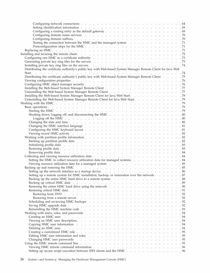
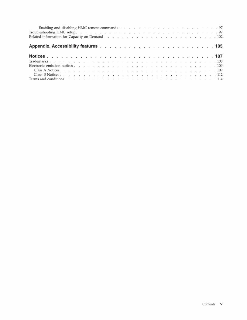
The following figures show representations of private and open networks:
Managing the Hardware Management Console (HMC) 13

Figure 2. Private network: direct connection
14 System i and System p: Managing the Hardware Management Console (HMC)
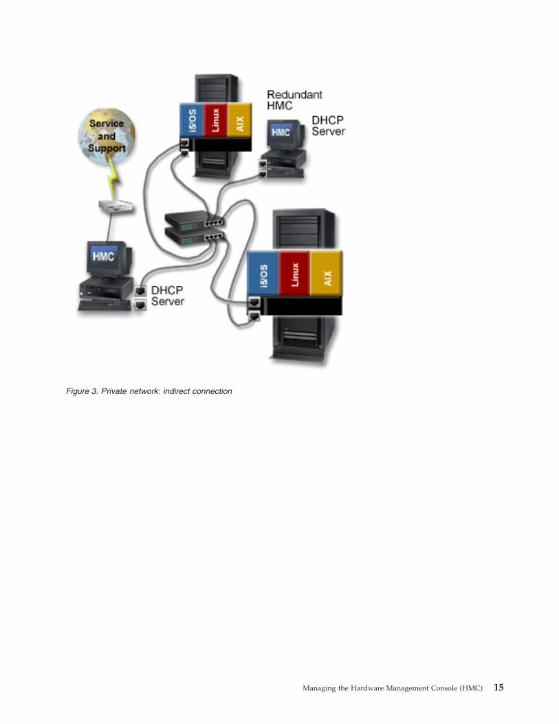
Figure 3. Private network: indirect connection
Managing the Hardware Management Console (HMC) 15
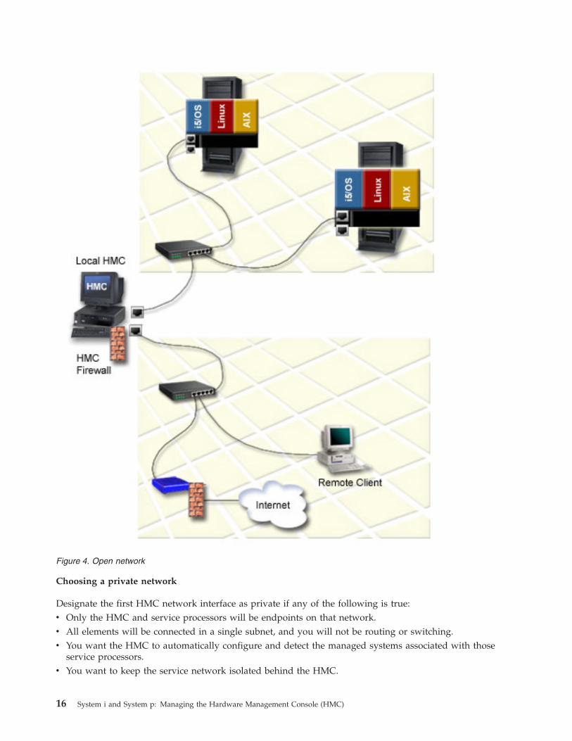
Choosing a private network
Designate the first HMC network interface as private if any of the following is true:v Only the HMC and service processors will be endpoints on that network.v All elements will be connected in a single subnet, and you will not be routing or switching.v You want the HMC to automatically configure and detect the managed systems associated with those
service processors.v You want to keep the service network isolated behind the HMC.
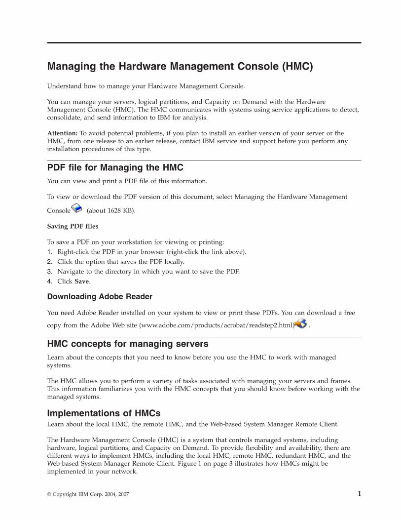
Figure 4. Open network
16 System i and System p: Managing the Hardware Management Console (HMC)

Choosing an open network
Designate the first network interface as open if you want to run the communications between the HMCand the service processors across an open network that crosses multiple subnets or has other devices onthe network.
For more information about choosing a network type, see “Selecting a private or open network” on page65.
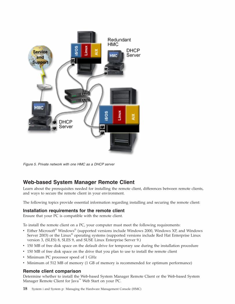
HMC as a DHCP serverYou can use the HMC as a DHCP server.
If you want to configure the first network interface as a private network, you can select from a range ofIP addresses for the DHCP server to assign to its clients. The selectable address ranges include segmentsfrom the standard nonroutable IP address ranges.
In addition to these standard ranges, a special range of IP addresses is reserved for IP addresses. Thisspecial range can be used to avoid conflicts in cases where the HMC-attached open networks are usingone of the nonroutable address ranges. Based on the range selected, the HMC network interface on theprivate network will be automatically assigned the first IP address of that range, and the serviceprocessors will then be assigned addresses from the rest of the range.
The DHCP server in the HMC uses automatic allocation, which means that each unique service processorEthernet interface will be reassigned exactly the same IP address each time it is started. Each Ethernetinterface has a unique identifier based upon a built-in Media Access Control (MAC) address, whichallows the DHCP server to reassign the same IP parameters. If you are using an HMC Version 7 or later,you can configure both eth0 and eth1 HMC ports to serve DHCP addresses.
Managing the Hardware Management Console (HMC) 17
Web-based System Manager Remote ClientLearn about the prerequisites needed for installing the remote client, differences between remote clients,and ways to secure the remote client in your environment.
The following topics provide essential information regarding installing and securing the remote client:
Installation requirements for the remote clientEnsure that your PC is compatible with the remote client.
To install the remote client on a PC, your computer must meet the following requirements:v Either Microsoft® Windows® (supported versions include Windows 2000, Windows XP, and Windows
Server 2003) or the Linux® operating systems (supported versions include Red Hat Enterprise Linuxversion 3, (SLES) 8, SLES 9, and SUSE Linux Enterprise Server 9.)
v 150 MB of free disk space on the default drive for temporary use during the installation procedurev 150 MB of free disk space on the drive that you plan to use to install the remote clientv Minimum PC processor speed of 1 GHzv Minimum of 512 MB of memory (1 GB of memory is recommended for optimum performance)
Remote client comparisonDetermine whether to install the Web-based System Manager Remote Client or the Web-based SystemManager Remote Client for Java™ Web Start on your PC.
Figure 5. Private network with one HMC as a DHCP server
18 System i and System p: Managing the Hardware Management Console (HMC)
You can access your HMC remotely by installing the Web-based System Manager remote client on yourPC. The remote client provides great flexibility by allowing you to manage your system from virtuallyanywhere you have a PC. You can use either one of these clients: the Web-based System Manager RemoteClient and the Web-based System Manager Remote Client for Java Web Start. After you start the remoteclient, there is no difference between the two.
The following table lists the similarities and differences between the remote clients:
Table 2. Comparisons between the Web-based System Manager Remote Client for Java Web Start and theWeb-based System Manager Remote Client
Web-based System Manager Remote Client for JavaWeb Start Web-based System Manager Remote Client
v Available for Linux and Windows platforms
v Checks for updates every time it opens, and if updatesare available, downloads them automatically
v Launches from the Java Web Start console
v Automatic update downloads might impactperformance if you are using a cable modem or DSLconnection
v Requires an HTTP server
v Available for Linux and Windows platforms
v Updates require that you uninstall the previousversion and install the current version
v Installs through an InstallShield wizard
v You can select the installation location
System Manager SecurityUnderstand how to secure the HMCs in your environment.
System Manager Security ensures that the HMC can operate securely in client/server mode. Servers andclients communicate over the Secure Sockets Layer (SSL) protocol, which provides server authentication,data encryption, and data integrity. Each System Manager server has its own private key and a certificateof its public key signed by a certificate authority (CA) that is trusted by the System Manager clients. Theprivate key and the server certificate are stored in the server’s private key ring file. Each client must havea public key that contains the certificate of the trusted CA.
A Certificate Authority (CA) is a trusted central administrative entity (a local HMC in this situation) thatcan issue digital certificates to clients and servers (HMC4 in Figure 6 on page 20). The trust in the CA isthe foundation of trust in the certificate as a valid credential. A CA uses its private key to create a digitalsignature on the certificate that it issues to validate the certificate’s origin. Others, such as SystemManager clients, can use the CA certificate’s public key to verify the authenticity of the certificates thatthe CA issues and signs.
Every digital certificate has a pair of associated cryptographic keys. This pair of keys consists of a publickey and a private key. A public key is part of the owner’s digital certificate and is available for anyone touse. A private key, however, is protected by and available only to the owner of the key. This limitedaccess ensures that communications that use the key are kept secure. The owner of a certificate can usethese keys to take advantage of the cryptographic security features that the keys provide. For example,the certificate owner can use a certificate’s private key to ″sign″ and encrypt data sent between clientsand servers, such as messages, documents, and code objects. The recipient of the signed object can thenuse the public key contained in the signer’s certificate to decrypt the signature. Such digital signaturesensure the reliability of an object’s origin and provide a means of checking the integrity of the object.
A server is a an HMC you want to access remotely. In Figure 6 on page 20, HMCs 1, 3, and 4 are servers.A client is a system from which you want to access other HMCs remotely. In Figure 6 on page 20,Web-based System Manager Remote Clients A, B, and C, and HMCs 1, 2, and 5 are clients. As shown inFigure 6 on page 20, you can configure multiple servers and clients in your private and open networks.
Managing the Hardware Management Console (HMC) 19
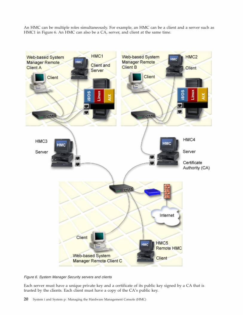
An HMC can be multiple roles simultaneously. For example, an HMC can be a client and a server such asHMC1 in Figure 6. An HMC can also be a CA, server, and client at the same time.
Each server must have a unique private key and a certificate of its public key signed by a CA that istrusted by the clients. Each client must have a copy of the CA’s public key.
Figure 6. System Manager Security servers and clients
20 System i and System p: Managing the Hardware Management Console (HMC)
The following is an overview of tasks involved in “Installing and securing the remote client” on page 72:1. Configure one HMC as a Certificate Authority (CA).2. Use this HMC to generate private keys for the servers.3. Install the private keys on the servers.4. Configure the servers as secure System Manager servers.5. Distribute the CA’s public key to the servers or clients.
Note: Tasks 3 and 5 are completed by copying the keys to diskette and installing them on the servers orclients.
Back up the HMC at regular intervalsBack up the HMC at regular intervals so that the HMC can be restored in the event of an HMC hardwaremalfunction.
The backup saves important HMC configuration information, including the following:v User IDs and rolesv Network configuration informationv Security configuration settingsv Updated Licensed Machine Code componentsv Partition profile definitions and snapshots
For more information about backing up the HMC, see Backing up critical HMC data. You can alsoschedule an automatic backup of HMC configuration information.
The HMC keeps a default backup file of the partition data locally, and also on the managed system. Thebackup file on the managed system is updated each time the HMC partition configuration changes.
If the managed system is in the recovery operating state, the HMC has determined that the partition datastored on the managed system is corrupted, or possibly lost due to a parts-replacement service action.Because you can overwrite the partition profile data on the managed system with the current partitionprofile information stored on the HMC, it is important for you to also keep a backup copy of the HMC,with the partition profile data. It is especially important that you back up your HMC data in thefollowing instances:v After you change partition profile properties on a managed systemv Before you update managed system Licensed Internal Codev After you reinstall the HMC machine code or apply corrective service to the HMCv After you upgrade the HMC machine version to a new level
Installing the HMCLearn how to cable and configure the HMC, including installing the HMC into a rack and configuringnetwork connections, security, and service applications.
To set up the Hardware Management Console (HMC), you must complete the following groups of tasks:cabling the HMC to the managed server, gathering configuration settings for your installation, andconfiguring the HMC. The HMC can be a stand-alone HMC or an HMC you plan to install in a rack. Usethe following topics to complete these tasks.
Note: When you have completed the HMC setup, do not power off or disconnect the HMC from themanaged system. If the HMC is powered off or disconnected from a nonpartitioned managed system fora period of 14 days, the managed system will no longer recognize the HMC. If this situation occurs andthe managed system fails to recognize the HMC, return to this topic and set up the HMC again.
Managing the Hardware Management Console (HMC) 21
If your system is partitioned, the 14-day time limit does not apply. See the “Postconfiguration steps forthe HMC” on page 71 topic.
If you are setting up the HMC along with the setup of a new server, you must perform these tasks inconjunction with other tasks related to your server setup. See Initial server setup for detailed instructions.
To learn more about how to cluster your systems using InfiniBand, see Clustering systems usingInfiniBand (IB) hardware.
Cabling the HMCConnect the HMC cables, connect the Ethernet cable, and connect the HMC to a power source.
DANGER
Electrical voltage and current from power, telephone, and communication cables are hazardous.
To avoid a shock hazard:
v Do not connect or disconnect any cables or perform installation, maintenance, or reconfigurationof this product during an electrical storm.
v Connect all power cords to a properly wired and grounded electrical outlet. Ensure outletsupplies proper voltage and phase rotation according to the system rating plate.
v Connect any equipment that will be attached to this product to properly wired outlets.
v When possible, use one hand only to connect or disconnect signal cables.
v Never turn on any equipment when there is evidence of fire, water, or structural damage.
v Disconnect the attached power cords, telecommunications systems, networks, and modems beforeyou open the device covers, unless instructed otherwise in the installation and configurationprocedures.
v Connect and disconnect cables as described below when installing, moving, or opening covers onthis product or attached devices.
To Disconnect:
1. Turn everything OFF (unless instructed otherwise).
2. Remove power cords from the outlet.
3. Remove signal cables from connectors.
4. Remove all cables from devices.
To Connect:
1. Turn everything OFF (unless instructed otherwise)
2. Attach all cables to devices.
3. Attach signal cables to connectors.
4. Attach power cords to outlet.
5. Turn device ON.
(D005)
Use the following instructions to help you cable your rack-mounted or stand-alone HMC.
Attention: Do not plug the power cords into the electrical outlet until you are instructed to do so.1. Choose from the following options:
v If you are using an HMC Version 6 or earlier, continue with step 2 on page 23.v If you are using a an HMC Version 7 or later, continue with step 3 on page 23.
22 System i and System p: Managing the Hardware Management Console (HMC)
2. Use the Specifications for HMC to help ensure that you position the HMC in the correct location.Then continue with step 4.
3. Ensure that you position the HMC in the correct location. Then continue with step 4.4. Choose from the following options:
v If you are installing a rack-mounted HMC, continue with step 5.v If you are installing a stand-alone HMC, continue with step 6 on page 24.
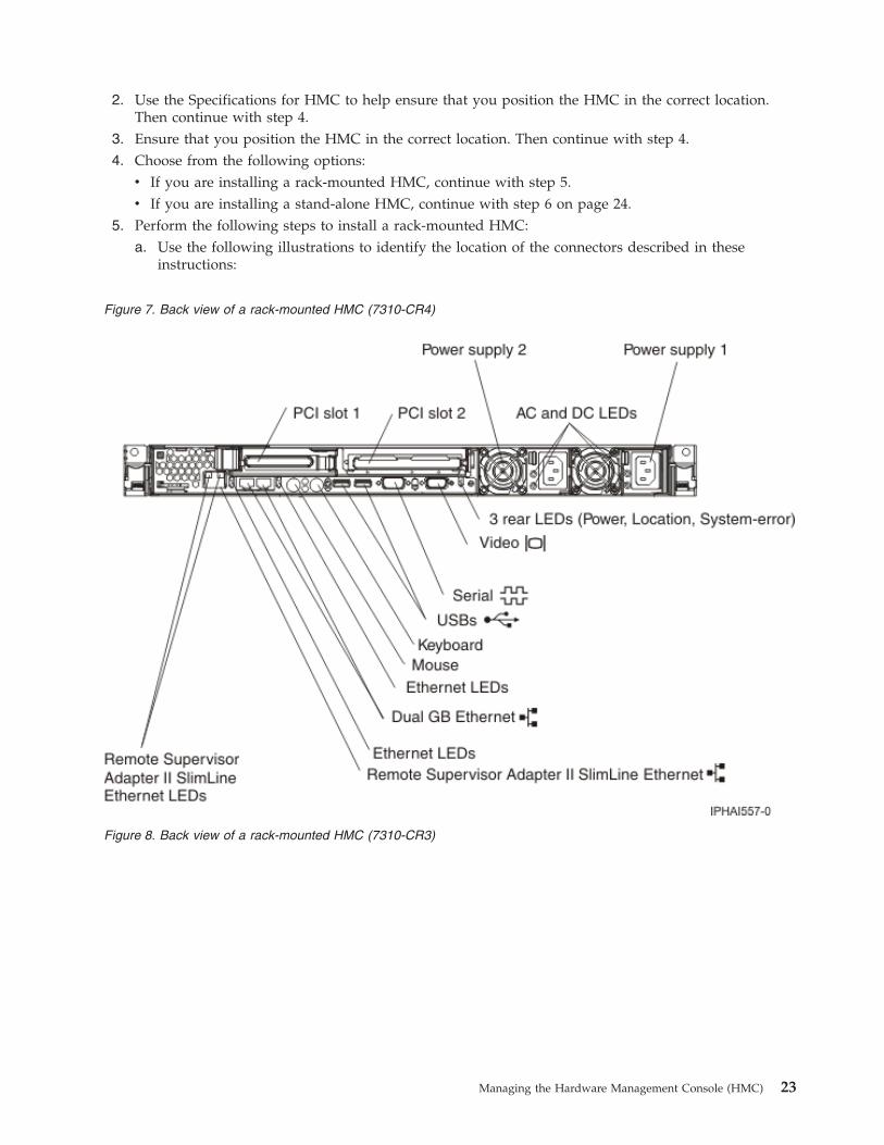
5. Perform the following steps to install a rack-mounted HMC:a. Use the following illustrations to identify the location of the connectors described in these
instructions:
Figure 7. Back view of a rack-mounted HMC (7310-CR4)
Figure 8. Back view of a rack-mounted HMC (7310-CR3)
Managing the Hardware Management Console (HMC) 23
b. Install the HMC into a rack. When you are finished installing the HMC into a rack, continue withthe next step.
c. Choose from the following options:v If you are using an HMC Version 6 or earlier, continue with step 5d.v If you are using a an HMC Version 7 or later, continue with step 5f.
d. Connect the monitor, keyboard, and mouse:For connection to a model 7310-CR2 HMC, connect the keyboard and display to the C2T-to-KVM(keyboard, video, mouse) adapter breakout cable that you have previously attached to the HMC.The mouse is integrated with the keyboard.If you are using a stand-alone monitor, keyboard, and mouse, read the following:v For connection to a model 7310-CR2 HMC, connect the keyboard and display to the
C2T-to-KVM (keyboard, video, mouse) adapter breakout cable that you have previouslyattached to the HMC. If your keyboard and mouse use USB connections, you can also connectthem to the USB ports on the front panel of the HMC.
v For connection to a model 7310-CR3 HMC, connect the keyboard, display, and mouse usingthe USB conversion option cable.
e. Continue with step 7 on page 29.f. Connect the keyboard, display, and mouse using the USB conversion option cable.g. Continue with step 7 on page 29.
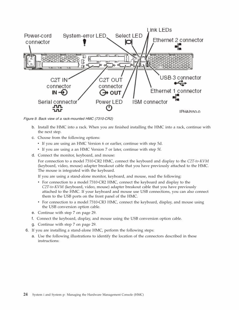
6. If you are installing a stand-alone HMC, perform the following steps:a. Use the following illustrations to identify the location of the connectors described in these
instructions:
Figure 9. Back view of a rack-mounted HMC (7310-CR2)
24 System i and System p: Managing the Hardware Management Console (HMC)
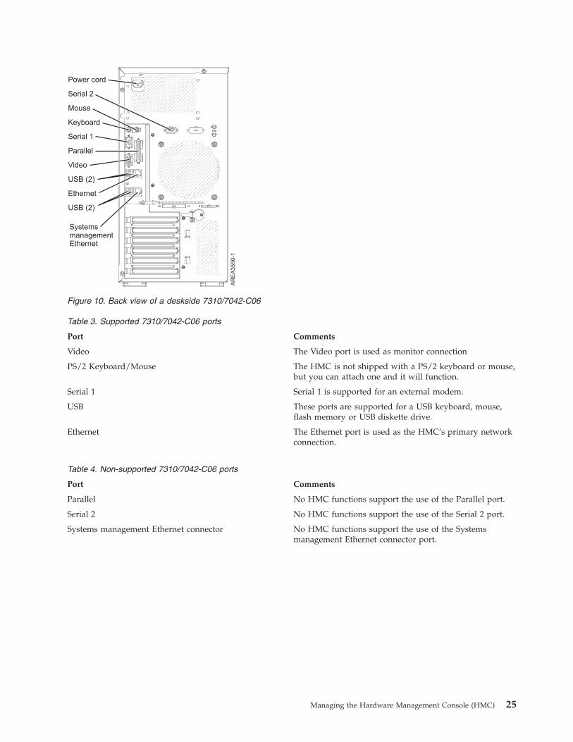
Table 3. Supported 7310/7042-C06 ports
Port Comments
Video The Video port is used as monitor connection
PS/2 Keyboard/Mouse The HMC is not shipped with a PS/2 keyboard or mouse,but you can attach one and it will function.
Serial 1 Serial 1 is supported for an external modem.
USB These ports are supported for a USB keyboard, mouse,flash memory or USB diskette drive.
Ethernet The Ethernet port is used as the HMC’s primary networkconnection.
Table 4. Non-supported 7310/7042-C06 ports
Port Comments
Parallel No HMC functions support the use of the Parallel port.
Serial 2 No HMC functions support the use of the Serial 2 port.
Systems management Ethernet connector No HMC functions support the use of the Systemsmanagement Ethernet connector port.
Figure 10. Back view of a deskside 7310/7042-C06
Managing the Hardware Management Console (HMC) 25
Serial 1
Keyboard
Mouse
Power cord
Parallel
Video
USB (2)
Ethernet
Serial 2
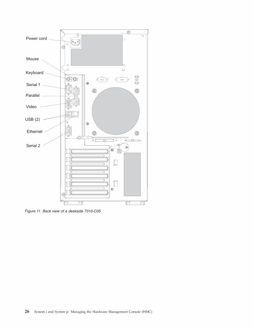
Figure 11. Back view of a deskside 7310-C05
26 System i and System p: Managing the Hardware Management Console (HMC)
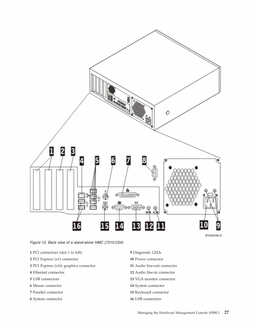
1 PCI connectors (slot 1 to left) 9 Diagnostic LEDs
2 PCI Express (x1) connector 10 Power connector
3 PCI Express (x16) graphics connector 11 Audio line-out connector
4 Ethernet connector 12 Audio line-in connector
5 USB connectors 13 VGA monitor connector
6 Mouse connector 14 System connector
7 Parallel connector 15 Keyboard connector
8 System connector 16 USB connectors
Figure 12. Back view of a stand-alone HMC (7310-C04)
Managing the Hardware Management Console (HMC) 27
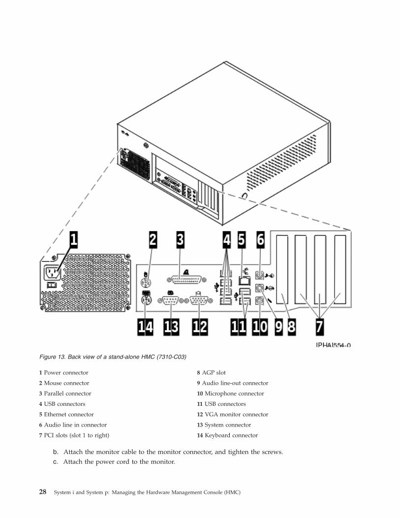
1 Power connector 8 AGP slot
2 Mouse connector 9 Audio line-out connector
3 Parallel connector 10 Microphone connector
4 USB connectors 11 USB connectors
5 Ethernet connector 12 VGA monitor connector
6 Audio line in connector 13 System connector
7 PCI slots (slot 1 to right) 14 Keyboard connector
b. Attach the monitor cable to the monitor connector, and tighten the screws.c. Attach the power cord to the monitor.
Figure 13. Back view of a stand-alone HMC (7310-C03)
28 System i and System p: Managing the Hardware Management Console (HMC)
d. Ensure that the voltage selection switch on the HMC is set to the voltage used in your worldregion. The voltage selection switch is red and is located near the power connector. Move theswitch so that the voltage used in your world region is displayed.
e. Plug the power cord into the HMC.f. Connect the keyboard and mouse:
v USB connections: Connect the keyboard and mouse to Universal Serial Bus (USB) ports on theHMC. You can connect the keyboard and mouse to the USB ports on the front or back panels.
Note: If you are using a stand-alone model 7310-C01 or 7310-C02 HMC, connect the keyboardand mouse to the front-panel USB ports only.
v PS/2-type connections: Connect the mouse and keyboard to their connectors on the back panelof the HMC.
v Universal Serial Bus ports: Connect the keyboard and mouse to Universal Serial Bus (USB)ports on the HMC. You can connect the keyboard and mouse to the USB ports on the front orback panels.
7. Connect the modem:
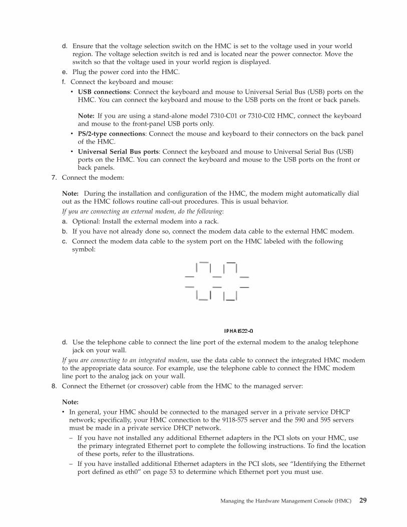
Note: During the installation and configuration of the HMC, the modem might automatically dialout as the HMC follows routine call-out procedures. This is usual behavior.If you are connecting an external modem, do the following:a. Optional: Install the external modem into a rack.b. If you have not already done so, connect the modem data cable to the external HMC modem.c. Connect the modem data cable to the system port on the HMC labeled with the following
symbol:
d. Use the telephone cable to connect the line port of the external modem to the analog telephonejack on your wall.
If you are connecting to an integrated modem, use the data cable to connect the integrated HMC modemto the appropriate data source. For example, use the telephone cable to connect the HMC modemline port to the analog jack on your wall.
8. Connect the Ethernet (or crossover) cable from the HMC to the managed server:
Note:
v In general, your HMC should be connected to the managed server in a private service DHCPnetwork; specifically, your HMC connection to the 9118-575 server and the 590 and 595 serversmust be made in a private service DHCP network.– If you have not installed any additional Ethernet adapters in the PCI slots on your HMC, use
the primary integrated Ethernet port to complete the following instructions. To find the locationof these ports, refer to the illustrations.
– If you have installed additional Ethernet adapters in the PCI slots, see “Identifying the Ethernetport defined as eth0” on page 53 to determine which Ethernet port you must use.
Managing the Hardware Management Console (HMC) 29

v You can verify that the Ethernet cable connection is active by observing the green status lights atboth the HMC and managed system Ethernet ports as your installation progresses.
v Connect the Ethernet port on the HMC to the Ethernet port that is labeled HMC1 on the managedserver. On the model 9118-575 server and the 590 and 595 servers, use the port labeled J00A on thefront bulk power control assembly.If you are connecting a second HMC to your managed server, connect to the Ethernet port that islabeled HMC2 on the managed server; on the 9118-575 server and the 590 and 595 servers, use theport labeled J00A on the rear bulk power control assembly.
9. If you use an external modem, plug the modem power supply cord into the HMC modem.10. Plug the power cords for the monitor, HMC, and HMC external modem into electrical outlets.
Note: Do not connect the managed system to a power source at this time.11. If you are setting up the HMC to manage a new server, go to Cabling your server. Click Select by
model and choose the model server you want to cable. Next, select the console you are using, andcomplete the remaining steps in that checklist.
12. If you are setting up the HMC to manage an existing server, continue with “Preparing for HMCconfiguration” on page 54.
Installing the HMC into a rackUse the table provided in this topic to gather required configuration settings that you need to knowbefore you begin the configuration steps.
The following steps are required to install the HMC into a rack.
If you are installing a 7310-CR47042-CR4, see “Installing the 7310-CR47042-CR4 into a rack” on page 36.
Note: You can grip any part of the hardware that is blue in color to remove it from or install it in themanaged system, open or close a latch, and so on.
DANGER
v Always lower the leveling pads on the rack cabinet.
v Always install stabilizer brackets on the rack cabinet.
v To avoid hazardous conditions due to uneven mechnical loading, always install the heaviestdevices in the bottom of the rack cabinet. Always install servers and optional devices startingfrom the bottom of the rack cabinet.
v Rack-mounted devices are not to be used as a shelf or work space. Do not place any object ontop of rack-mounted devices.
v Each rack cabinet might have more than one power cord. Be sure to disconnect all power cords inthe rack cabinet before servicing any device in the rack cabinet.
v Connect all devices installed in a rack cabinet to power devices installed in the same rackcabinet. Do not plug a power cord from a device installed in one rack cabinet into a powerdevice installed in a different rack cabinet.
v An electical outlet that is not correctly wired could place hazardous voltage on the metal parts ofthe system or the devices that attach to the system. It is the responsibility of the customer toensure that the outlet is correctly wired and grounded to prevent an electical shock.
30 System i and System p: Managing the Hardware Management Console (HMC)

CAUTION:
v Do not install a unit in a rack where the internal rack ambient temperatures will exceed themanufacturer’s recommended ambient temperature for all your rack-mounted devices.
v Do not install a unit in a rack where the air flow is compromised. Ensure that air flow is notblocked or reduced on any side, front, or back of a unit used for air flow through the unit.
v Consideration should be given to the connection of the equipment to the supply circuit so thatoverloading of the circuits does not compromise the supply wiring or overcurrent protection. Toprovide the correct power connection to a rack, refer to the rating labels located on the equipmentin the rack to determine the total power requirement of the supply circuit.
v (For sliding drawers.) Do not pull out or install any drawer or feature if the rack stabilizer bracketsare not attached to the rack. Do not pull out more than one drawer at a time. The rack may becomeunstable if you pull out more than one drawer at a time.
v (For fixed drawers.) This drawer is a fixed drawer and should not be moved for servicing unlessspecified by manufacturer. Attempting to move the drawer partially or completely out of the rackmay cause the rack to become unstable or cause the drawer to fall out of the rack.
(R001)
1. Use the following illustration to ensure that you have all the items that you need to install the HMCin your rack enclosure. If any items are missing or damaged, contact your place of purchase. Forfurther information about the rack hardware, refer to the documentation that was provided with therack enclosure.
Attention: Do not place any object weighing more than 50 kg (110 lbs) on top of devices mountedon the rack.
2. Starting with the slide rail that is marked LEFT/FRONT, complete the following tasks to prepare theslide rail for installation in the rack.a. To prevent the rail-adjustment bracket from moving during the next step, press and hold the
back of the rail-adjustment bracket 3.b. On the back end of the rail, while holding the blue tab 1 open, press the blue tab 2 to slide the
back rail-locking carrier toward the front end until the carrier clicks into the open position.c. On the front end of the rail, while holding the blue tab 1 open, press the blue tab 2 to slide the
front rail-locking carrier toward the back end until the carrier clicks into the open position.
Managing the Hardware Management Console (HMC) 31

3. Position the rail so that the pins on the back rail-locking carrier align with the holes on the backrail-mounting flange. Press the blue tab 1 to release the rail-locking carrier and secure the back of theslide rail onto the back rack-mounting flange.Attention: Ensure that the pins are fully extended through the mounting flange and slide rail 2.
If you need to adjust the slide-rail length, lift the tab 3 and extend the rail-adjustment bracket fromthe back of the slide rail until it is the appropriate length.
4. Making sure that the rail is level, align the pins 3 on the front rail-locking carrier to the frontrack-mounting flange 2. If you adjusted the rail length, push the front rail flange back.Press the blue tab 1 to release the rail-locking carrier and secure the front of the slide rail onto thefront rack-mounting flange.
32 System i and System p: Managing the Hardware Management Console (HMC)
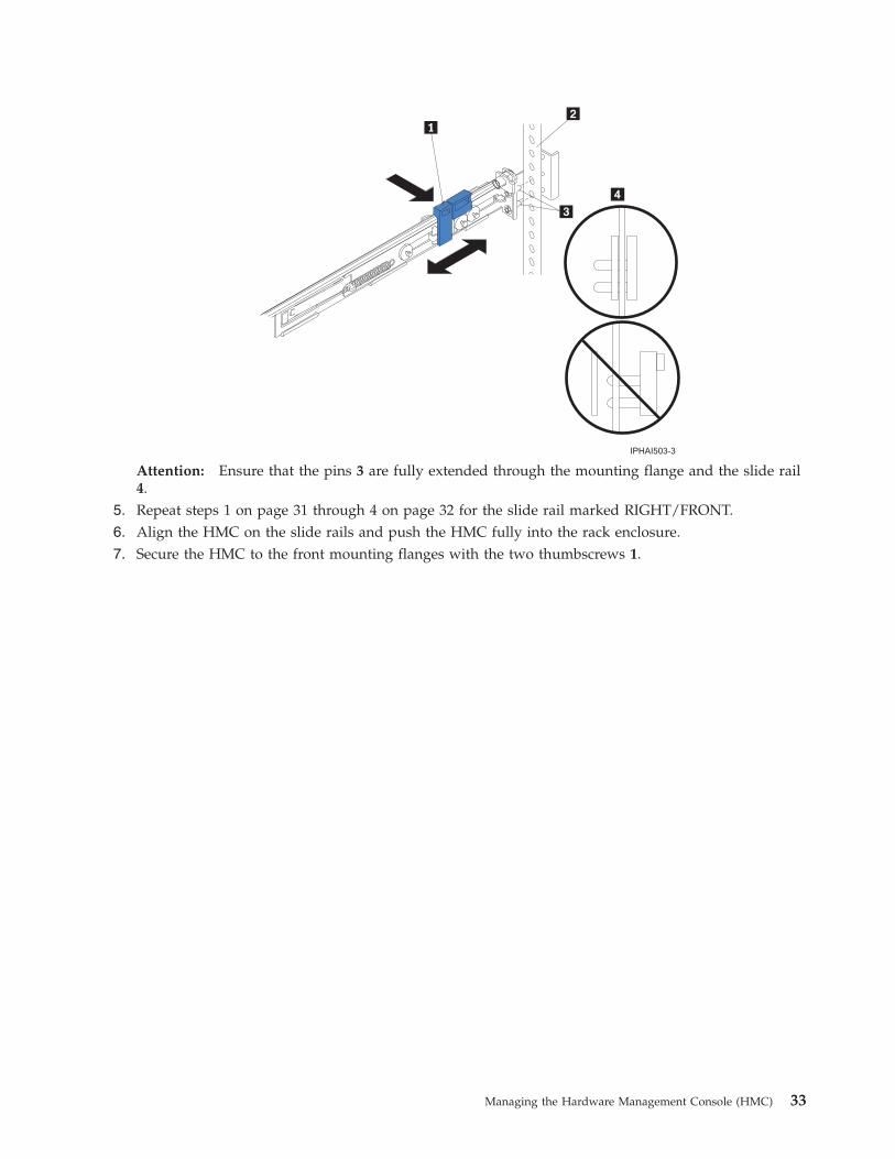
Attention: Ensure that the pins 3 are fully extended through the mounting flange and the slide rail4.
5. Repeat steps 1 on page 31 through 4 on page 32 for the slide rail marked RIGHT/FRONT.6. Align the HMC on the slide rails and push the HMC fully into the rack enclosure.7. Secure the HMC to the front mounting flanges with the two thumbscrews 1.
Managing the Hardware Management Console (HMC) 33
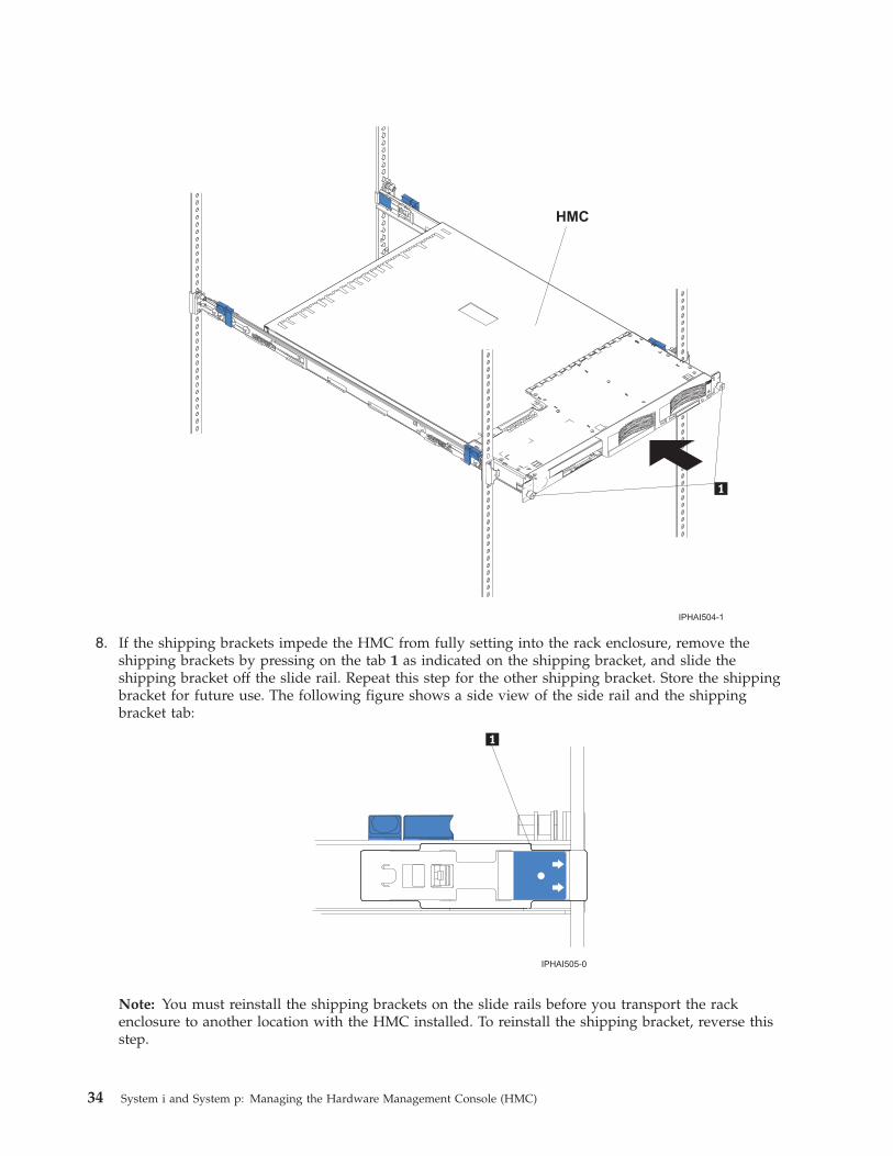
8. If the shipping brackets impede the HMC from fully setting into the rack enclosure, remove theshipping brackets by pressing on the tab 1 as indicated on the shipping bracket, and slide theshipping bracket off the slide rail. Repeat this step for the other shipping bracket. Store the shippingbracket for future use. The following figure shows a side view of the side rail and the shippingbracket tab:
Note: You must reinstall the shipping brackets on the slide rails before you transport the rackenclosure to another location with the HMC installed. To reinstall the shipping bracket, reverse thisstep.
34 System i and System p: Managing the Hardware Management Console (HMC)

9. If you are installing a 7310-CR2 HMC, connect the breakout cable (the C2T-to-KVM adapter cable forthe keyboard, monitor, and mouse that comes with your HMC) to the port labeled OUT on the backof the HMC, and connect the power cable to the back of the HMC. If you are installing a 7310-CR3HMC, connect the USB conversion option cable to a USB connector. Route the cables to the lower-leftcorner of the HMC (as viewed from the back), and use the cable straps 1 to secure the cables to theslide rails.
10. If you plan to transport the rack enclosure to another location with the HMC installed, complete thefollowing tasks to secure the HMC to the rack:
Note: To remove the HMC from the rack, reverse these instructions.a. Disconnect the cables from the back of the HMC.b. Slide the HMC out of the rack about 150 mm (6 inches), and insert the M6 screws in the front of
each slide rail 2.c. At the back of the rack, secure the HMC to the rack enclosure with M6 screws 1 and reconnect
the cables.
Managing the Hardware Management Console (HMC) 35
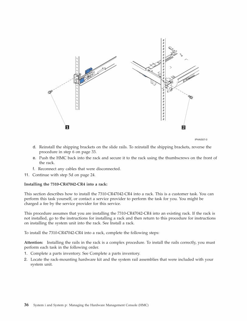
d. Reinstall the shipping brackets on the slide rails. To reinstall the shipping brackets, reverse theprocedure in step 6 on page 33.
e. Push the HMC back into the rack and secure it to the rack using the thumbscrews on the front ofthe rack.
f. Reconnect any cables that were disconnected.11. Continue with step 5d on page 24.
Installing the 7310-CR47042-CR4 into a rack:
This section describes how to install the 7310-CR47042-CR4 into a rack. This is a customer task. You canperform this task yourself, or contact a service provider to perform the task for you. You might becharged a fee by the service provider for this service.
This procedure assumes that you are installing the 7310-CR47042-CR4 into an existing rack. If the rack isnot installed, go to the instructions for installing a rack and then return to this procedure for instructionson installing the system unit into the rack. See Install a rack.
To install the 7310-CR47042-CR4 into a rack, complete the following steps:
Attention: Installing the rails in the rack is a complex procedure. To install the rails correctly, you mustperform each task in the following order.1. Complete a parts inventory. See Complete a parts inventory.2. Locate the rack-mounting hardware kit and the system rail assemblies that were included with your
system unit.
36 System i and System p: Managing the Hardware Management Console (HMC)
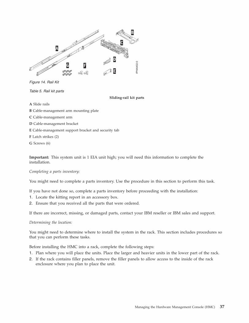
Table 5. Rail kit parts
Sliding-rail kit parts
A Slide rails
B Cable-management arm mounting plate
C Cable-management arm
D Cable-management bracket
E Cable-management support bracket and security tab
F Latch strikes (2)
G Screws (6)
Important: This system unit is 1 EIA unit high; you will need this information to complete theinstallation.
Completing a parts inventory:
You might need to complete a parts inventory. Use the procedure in this section to perform this task.
If you have not done so, complete a parts inventory before proceeding with the installation:1. Locate the kitting report in an accessory box.2. Ensure that you received all the parts that were ordered.
If there are incorrect, missing, or damaged parts, contact your IBM reseller or IBM sales and support.
Determining the location:
You might need to determine where to install the system in the rack. This section includes procedures sothat you can perform these tasks.
Before installing the HMC into a rack, complete the following steps:1. Plan where you will place the units. Place the larger and heavier units in the lower part of the rack.2. If the rack contains filler panels, remove the filler panels to allow access to the inside of the rack
enclosure where you plan to place the unit.
Figure 14. Rail Kit
Managing the Hardware Management Console (HMC) 37
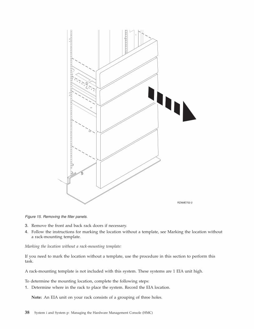
3. Remove the front and back rack doors if necessary.4. Follow the instructions for marking the location without a template, see Marking the location without
a rack-mounting template.
Marking the location without a rack-mounting template:
If you need to mark the location without a template, use the procedure in this section to perform thistask.
A rack-mounting template is not included with this system. These systems are 1 EIA unit high.
To determine the mounting location, complete the following steps:1. Determine where in the rack to place the system. Record the EIA location.
Note: An EIA unit on your rack consists of a grouping of three holes.
Figure 15. Removing the filler panels.
38 System i and System p: Managing the Hardware Management Console (HMC)

2. Facing the front of the rack and working from the right side, place a supplied self-adhesive dot nextto the top hole of the EIA unit.
Note: The self-adhesive dots are used to aid in identifying locations on the rack. If you no longerhave any of the dots, use some other form of marking tool to aid you in identifying hole locations (forexample, tape, a marker, or pencil). If you are installing slide rails, place a mark or self-adhesive doton the lower and the middle hole of each EIA unit.
3. Place another self-adhesive dot next to the bottom hole of the above the EIA unit.
Note: If you are counting the holes, begin with the hole identified by the first dot and count up twoholes. Place the second dot next to the third hole.
4. Repeat step 1 on page 38 for the corresponding holes located on the left side of the rack.5. Go to the back of the rack.6. On the right side, find the EIA unit that corresponds to the bottom EIA unit marked on the front of
the rack.7. Place a self-adhesive dot at the bottom EIA unit.8. Place a self-adhesive dot at the top hole of the EIA unit.9. Mark the corresponding holes on the left side of the rack.
Installing the slide rails into the rack:
You might need to install slide rails into the rack. Use the procedure in this section to perform this task.
Attention: Installing the rails in the rack is a complex procedure. To install the rails correctly, you mustperform each task in the following order.
To install the slide rails into the rack, complete the following steps:1. Insert the right-slide rail A marked ″right″ into the back-right rack mounting flange B locations. The
two rail pins will protrude through the bottom and middle holes B on the EIA unit.
Managing the Hardware Management Console (HMC) 39

2. Push on the end of the rail A to compress the rail’s spring-loaded mechanism, and insert the rail intothe front-right rack mounting flange B locations. The rail will decompress and the two rail pins willprotrude through the bottom and middle holes B on the EIA unit.
3. Repeat these steps to install the left-slide rail marked ″left″ into the rack.4. From the front of the rack, place the latch strike C over the pins. Finger-tighten the captive screw D
into the top pin of front of the right-slide rail A.
Figure 16. Installing the right-slide rail into the back of the rack
Figure 17. Installing the right-slide rail into the front of the rack
40 System i and System p: Managing the Hardware Management Console (HMC)
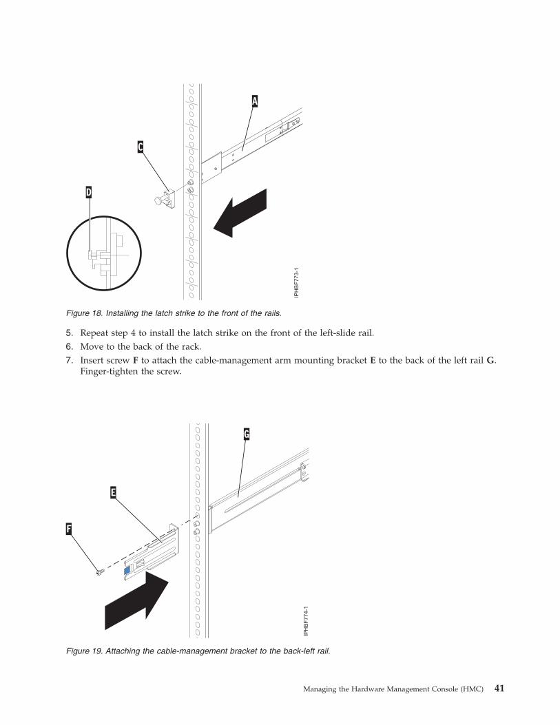
5. Repeat step 4 to install the latch strike on the front of the left-slide rail.6. Move to the back of the rack.7. Insert screw F to attach the cable-management arm mounting bracket E to the back of the left rail G.
Finger-tighten the screw.
Figure 18. Installing the latch strike to the front of the rails.
Figure 19. Attaching the cable-management bracket to the back-left rail.
Managing the Hardware Management Console (HMC) 41

8. The cable-management arm support bracket can be used to secure the cable-management arm duringtransport. If the mechanism is engaged after the cable-management arm is installed, you will not beable to slide the system from the rack. If you do not plan to transport this system, continue with thenext step. If you plan to transport this system, insert screw I to attach the cable-management armsupport bracket H to the back-right rail A. Finger-tighten the screw.
Installing the HMC on the slide rails:
You might need to install the HMC on the slide rails. Use the procedure in this section to perform thistask.
Before installing the HMC on the slide rails, ensure that the stabilizers are extended and the rackstabilizer bracket is attached to the bottom front of the rack to prevent the rack from falling forwardwhen the rails are pulled out of the rack. Refer to Installing the rack.
To install the HMC on the slide-rail assembly, complete the following steps:1. Remove the shipping bracket that covers the power supplies from the right rear of the HMC. To
remove the shipping bracket, push to the bracket to the right and swivel the shipping bracket off theHMC.
2. From the front of the rack, fully extend the slide rails until the rails lock into place in the extendedposition A.Attention: The latch strikes on the front of the rail and the cable-management arm brackets must beinstalled before installing an HMC onto the rails. If these parts are not installed, the installation maycause the rails to compress and the HMC may fall out of the rack.
Figure 20. Attaching the cable-management support bracket to the back-right rail.
42 System i and System p: Managing the Hardware Management Console (HMC)
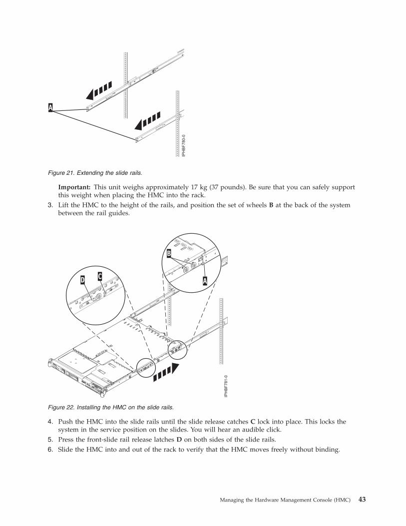
Important: This unit weighs approximately 17 kg (37 pounds). Be sure that you can safely supportthis weight when placing the HMC into the rack.
3. Lift the HMC to the height of the rails, and position the set of wheels B at the back of the systembetween the rail guides.
4. Push the HMC into the slide rails until the slide release catches C lock into place. This locks thesystem in the service position on the slides. You will hear an audible click.
5. Press the front-slide rail release latches D on both sides of the slide rails.6. Slide the HMC into and out of the rack to verify that the HMC moves freely without binding.
Figure 21. Extending the slide rails.
Figure 22. Installing the HMC on the slide rails.
Managing the Hardware Management Console (HMC) 43
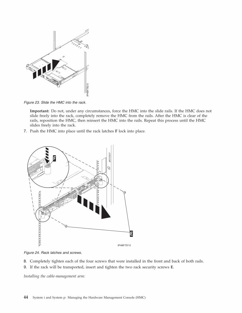
Important: Do not, under any circumstances, force the HMC into the slide rails. If the HMC does notslide freely into the rack, completely remove the HMC from the rails. After the HMC is clear of therails, reposition the HMC, then reinsert the HMC into the rails. Repeat this process until the HMCslides freely into the rack.
7. Push the HMC into place until the rack latches F lock into place.
8. Completely tighten each of the four screws that were installed in the front and back of both rails.9. If the rack will be transported, insert and tighten the two rack security screws E.
Installing the cable-management arm:
Figure 23. Slide the HMC into the rack.
Figure 24. Rack latches and screws.
44 System i and System p: Managing the Hardware Management Console (HMC)

You might need to install the cable-management arm. Use the procedure in this section to perform thistask.
To install the cable-management arm, complete the following steps:1. From the back of the rack, locate the cable-management arm flange A located on the fixed back
portion of the left system rail assembly (viewing from the back of the rack).2. Attach the cable-management arm clasp B to the rail by pushing the clasp onto the rail until it locks
into place.
3. Attach the other end of the cable-management arm C to the back of the HMC. Align the tabs D onthe cable-management arm with the slots E on the back of the HMC.
4. Slide the cable-management arm to the left, securing it into place. Make sure all the tabs fit into theslots.
5. Push the locking lever F into the locked position. Ensure that the cable-management arm C is level sothat it moves freely.
Installing the external modem into a rackThe modem tray supports the MultiTech Systems MultiModem II Model MT5600BA Series modem.
The modem tray attaches to the system rack and holds one or two standalone modems, gateways, orother networking equipment. The modem tray occupies 1 Electronics Industries Association (EIA)location in the rack. If only one modem or other networking unit is installed in the modem tray, a blankfiller is used in the empty mounting location to ensure that proper airflow is maintained in the rack. Theblank filler also ensures that electromagnetic interference is confined within the rack.
Check the power source on the rack:
Ensure that the correct power source is available on the rack. The MultiTech Systems MultiModem IIModel MT5600BA Series modems are equipped to operate on 120 V ac, 60 Hz, 16 W, or 230 V/50 Hz(international). Racks have power distribution buses (PDB) 2 that supply the correct alternating currentand power to operate the modems installed in the modem tray. The main power source plug on the rackis indicated by 1. The PDBs are located at the back and bottom of the rack as shown in the followingillustration:
Figure 25. Cable-management arm and system unit.
Managing the Hardware Management Console (HMC) 45

Install the modem into the modem tray:
1. Remove the screw 5 securing the retaining bracket 6 at the back of the modem tray 1. The retainingbracket can now be removed from the modem tray. See the following illustration.
2. Position the modem in the tray 4 or 7 with the front of the modem facing the front of the tray. Slidethe front of the modem under the two retainer tabs 8.
3. Position the retaining bracket that was removed in step 1 over the back corner of the modem.4. Align the screw hole in the retaining bracket to the hole at the back of the modem tray.
46 System i and System p: Managing the Hardware Management Console (HMC)
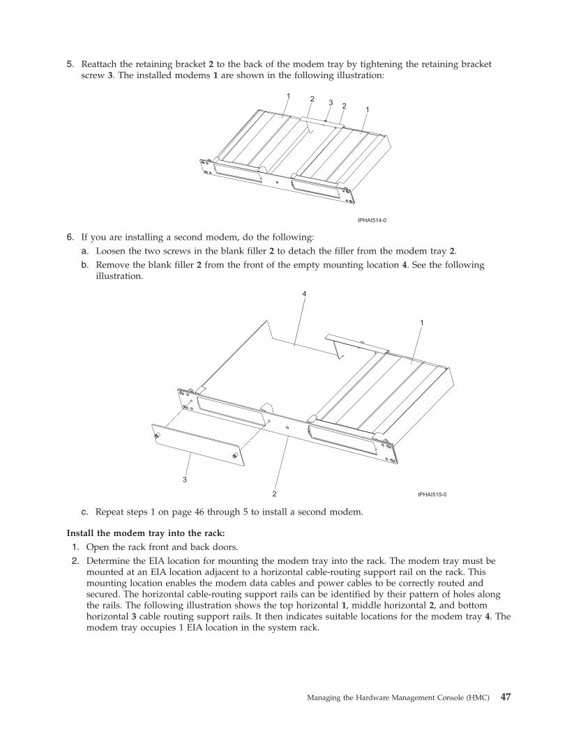
5. Reattach the retaining bracket 2 to the back of the modem tray by tightening the retaining bracketscrew 3. The installed modems 1 are shown in the following illustration:
6. If you are installing a second modem, do the following:a. Loosen the two screws in the blank filler 2 to detach the filler from the modem tray 2.b. Remove the blank filler 2 from the front of the empty mounting location 4. See the following
illustration.
c. Repeat steps 1 on page 46 through 5 to install a second modem.
Install the modem tray into the rack:
1. Open the rack front and back doors.2. Determine the EIA location for mounting the modem tray into the rack. The modem tray must be
mounted at an EIA location adjacent to a horizontal cable-routing support rail on the rack. Thismounting location enables the modem data cables and power cables to be correctly routed andsecured. The horizontal cable-routing support rails can be identified by their pattern of holes alongthe rails. The following illustration shows the top horizontal 1, middle horizontal 2, and bottomhorizontal 3 cable routing support rails. It then indicates suitable locations for the modem tray 4. Themodem tray occupies 1 EIA location in the system rack.
Managing the Hardware Management Console (HMC) 47
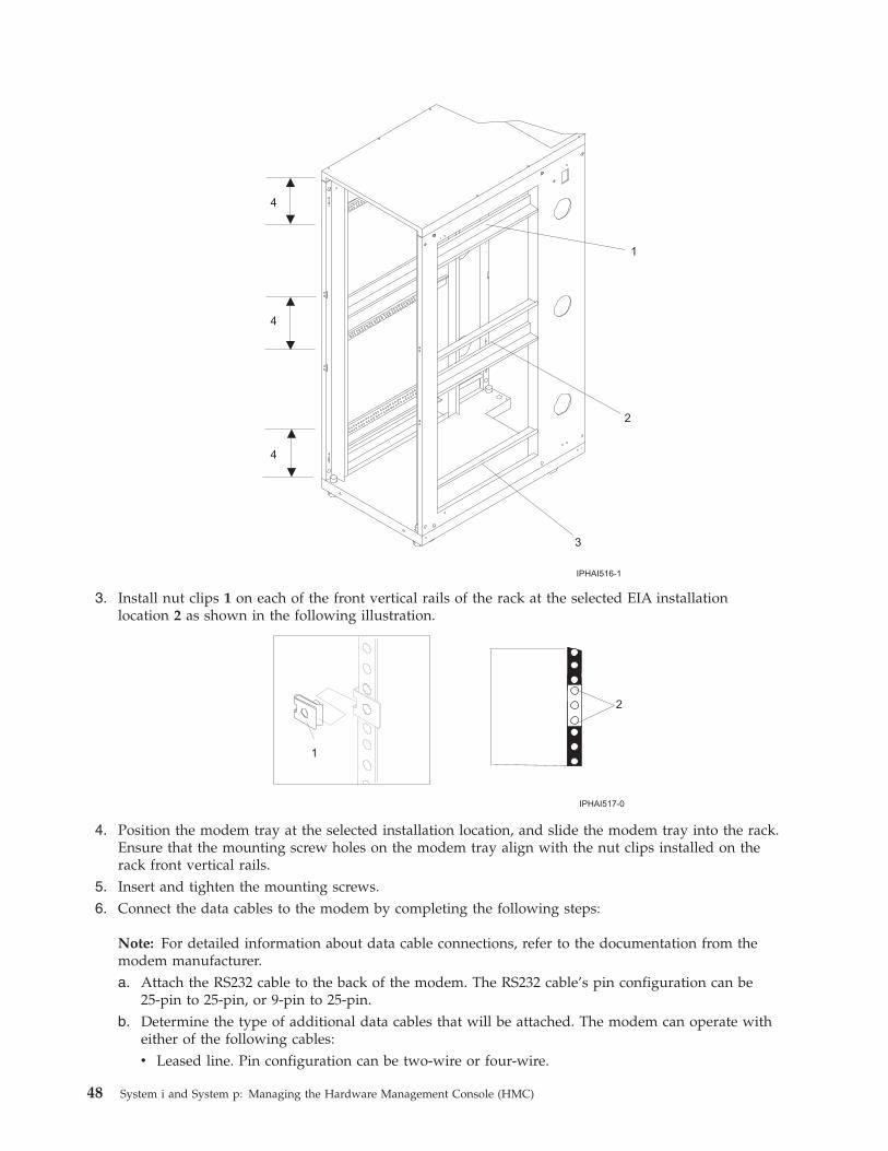
3. Install nut clips 1 on each of the front vertical rails of the rack at the selected EIA installationlocation 2 as shown in the following illustration.
4. Position the modem tray at the selected installation location, and slide the modem tray into the rack.Ensure that the mounting screw holes on the modem tray align with the nut clips installed on therack front vertical rails.
5. Insert and tighten the mounting screws.6. Connect the data cables to the modem by completing the following steps:
Note: For detailed information about data cable connections, refer to the documentation from themodem manufacturer.a. Attach the RS232 cable to the back of the modem. The RS232 cable’s pin configuration can be
25-pin to 25-pin, or 9-pin to 25-pin.b. Determine the type of additional data cables that will be attached. The modem can operate with
either of the following cables:v Leased line. Pin configuration can be two-wire or four-wire.
48 System i and System p: Managing the Hardware Management Console (HMC)

v Telephone line.c. Attach the data cables to the back of the modem. Follow the manufacturer’s documentation to
ensure that the pin configuration is correct.
Note: To gain adequate access to the back of the modem, it might be necessary to slide thesystem drawer that is located above or below the modem tray out of the rack.
7. Peel off the adhesive covering 2 located on the bottom of each cable clamp 3. Position two cableclamps 3 to each side of the modem tray as shown in the following illustration. Press firmly toadhere the cable clamps 3 to the modem tray. The cable clamps 3 will be used to route cables to thehorizontal rack rail.
8. Connect the modem power supply cord to the power connector located on the back of the modem.9. To avoid cables and the power cord getting pinched between units, route the cables and power cord
through the cable clamps located on the side of the modem tray.10. Route the power cord and data cables from the modem to the appropriate horizontal rail adjacent to
the modem tray installation location on the rack.
Note: Route the cables and power cord to the closest horizontal support rail. To avoid damage to thecables when other units are slid in or out, ensure the cables and power cord are routed within theEIA space for the modem tray.The horizontal support rails are located on both sides of the rack. The following illustration showsthe bottom 1, middle 2, and top 3 horizontal support rails. It also shows an example of a cable andpower cord route at the top of the rack 4 and on the horizontal rails 5.
Managing the Hardware Management Console (HMC) 49
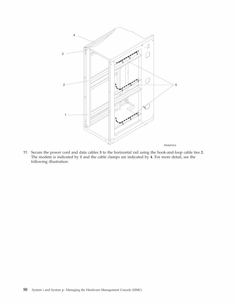
11. Secure the power cord and data cables 3 to the horizontal rail using the hook-and-loop cable ties 2.The modem is indicated by 1 and the cable clamps are indicated by 4. For more detail, see thefollowing illustration:
50 System i and System p: Managing the Hardware Management Console (HMC)

Note: Before securing the cables and cord, ensure that the connector on each cable or cord isaccessible to its destination (such as the data cable reaching the HMC and the power cord from thepower supply reaching the PDB).
12. Attach one strip of double-sided adhesive tape to the bottom of the power supply.
Note: The bottom of the power supply is the clear surface located opposite the side with the labelattached.
13. Position the power supply at the mounting location on the inside of the rack side panel, and press itfirmly to adhere the power supply to the rack.
14. Attach a strip of hook-and-loop cable ties to the back vertical rail of the rack. Do not connect thepower during the following step.
15. Route the power cord from the power supply to the PDB located at the back of the rack.
Complete the installation:
1. Connect the power cord from the modem to the PDB 2 located inside and at the back of the rack. Themain power source plug on the rack is indicated by 1. See the following illustration for the location ofthe PDB.
Managing the Hardware Management Console (HMC) 51
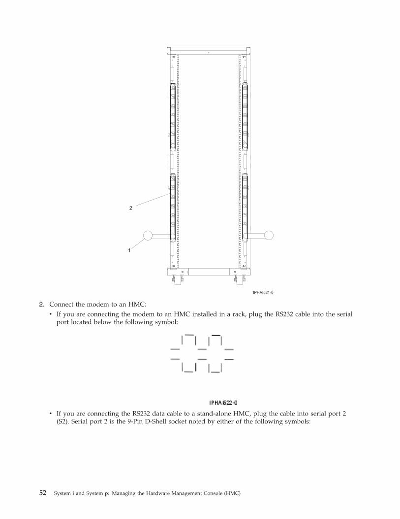
2. Connect the modem to an HMC:v If you are connecting the modem to an HMC installed in a rack, plug the RS232 cable into the serial
port located below the following symbol:
v If you are connecting the RS232 data cable to a stand-alone HMC, plug the cable into serial port 2(S2). Serial port 2 is the 9-Pin D-Shell socket noted by either of the following symbols:
52 System i and System p: Managing the Hardware Management Console (HMC)
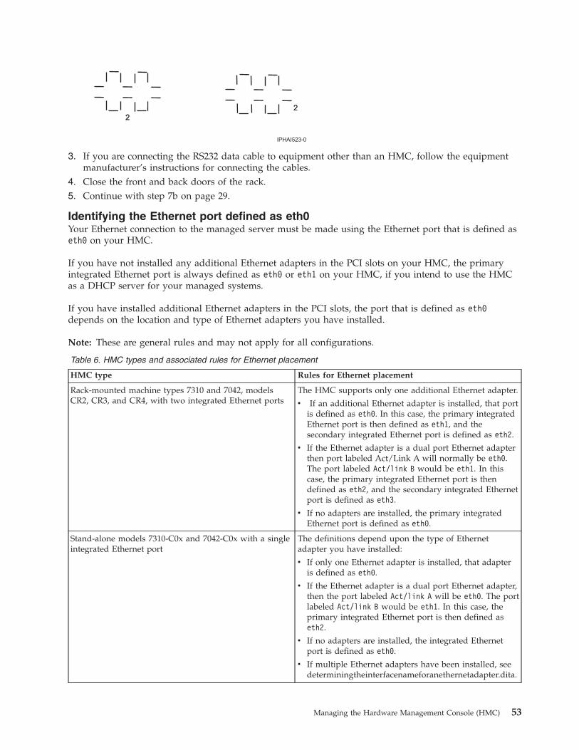
3. If you are connecting the RS232 data cable to equipment other than an HMC, follow the equipmentmanufacturer’s instructions for connecting the cables.
4. Close the front and back doors of the rack.5. Continue with step 7b on page 29.
Identifying the Ethernet port defined as eth0Your Ethernet connection to the managed server must be made using the Ethernet port that is defined aseth0 on your HMC.
If you have not installed any additional Ethernet adapters in the PCI slots on your HMC, the primaryintegrated Ethernet port is always defined as eth0 or eth1 on your HMC, if you intend to use the HMCas a DHCP server for your managed systems.
If you have installed additional Ethernet adapters in the PCI slots, the port that is defined as eth0depends on the location and type of Ethernet adapters you have installed.
Note: These are general rules and may not apply for all configurations.
Table 6. HMC types and associated rules for Ethernet placement
HMC type Rules for Ethernet placement
Rack-mounted machine types 7310 and 7042, modelsCR2, CR3, and CR4, with two integrated Ethernet ports
The HMC supports only one additional Ethernet adapter.
v If an additional Ethernet adapter is installed, that portis defined as eth0. In this case, the primary integratedEthernet port is then defined as eth1, and thesecondary integrated Ethernet port is defined as eth2.
v If the Ethernet adapter is a dual port Ethernet adapterthen port labeled Act/Link A will normally be eth0.The port labeled Act/link B would be eth1. In thiscase, the primary integrated Ethernet port is thendefined as eth2, and the secondary integrated Ethernetport is defined as eth3.
v If no adapters are installed, the primary integratedEthernet port is defined as eth0.
Stand-alone models 7310-C0x and 7042-C0x with a singleintegrated Ethernet port
The definitions depend upon the type of Ethernetadapter you have installed:
v If only one Ethernet adapter is installed, that adapteris defined as eth0.
v If the Ethernet adapter is a dual port Ethernet adapter,then the port labeled Act/link A will be eth0. The portlabeled Act/link B would be eth1. In this case, theprimary integrated Ethernet port is then defined aseth2.
v If no adapters are installed, the integrated Ethernetport is defined as eth0.
v If multiple Ethernet adapters have been installed, seedeterminingtheinterfacenameforanethernetadapter.dita.
Managing the Hardware Management Console (HMC) 53
Preparing for HMC configurationUse this section to gather required configuration settings that you need to know before you begin theconfiguration steps.
To successfully configure the HMC, you must understand related concepts, make decisions, and prepareinformation. For a more detailed look at the tasks required for HMC configuration preparation, seepreinstallationconfigurationworksheet.dita.
When you have completed this preparation step, go to “Configuring the HMC” on page 57.
This section describes planning information for how you want to connect your HMC to your server, toyour company network, and to your service provider. Review the related information in the followingtable to learn more about the decisions you need to make. You might choose to print this page to writedown your decisions, requirements, and settings for easy access during the configuration steps.
This information contains references to tasks that are not included in this PDF. You can access the IBMSystems Hardware Information Center on the HMC or on the Web. On the HMC, the information centeris in the Information Center and Setup Wizard folder. On the Web, the information center is athttp://www.ibm.com/server/library/infocenter. Select your geographical location, your languagepreference, and hardware.
Table 7. Preparing for configuration
Preparation task Where to find relatedinformation
If this is a second (redundant) HMC, ensure that the HMC code level of this HMCmatches the one you already have.
Optional: If you plan to create additional users, identify the following information:
v User IDs you want to create
v The user ID and password for each additional user you plan to create
v What role you plan to assign each user
Overview of roles
Determine whether you want to specify the media speed for each Ethernet adapteror let the HMC automatically detect the speed.
For initial setup, use automatic detection. However, in some situations, you mightwant to reduce the speed of the adapter. If you plan to specify the media speed foreach Ethernet adapter, identify the media speed and duplex mode for eachEthernet adapter; for example, 100 Mbps full duplex.
“Setting the media speed” onpage 64
Prepare the following contact information:
v Company name
v Administrator’s name
v E-mail address
v Telephone numbers
v Fax numbers
v Street address and telephone number for the location of the HMC
Contact your systemadministrator.
54 System i and System p: Managing the Hardware Management Console (HMC)
Table 7. Preparing for configuration (continued)
Preparation task Where to find relatedinformation
Determine what type of connection you want to configure to contact your serviceprovider:
v Internet VPN
v SSL connectivity with or without a SSL proxy
v The dial-up connection from the local HMC
This preparation task might involve corporate networking or security teams, or theinstallation of a phone line.
It is important that the connectivity checklist be completed before your system isinstalled.
Choosing your connectionmethod to your serviceprovider
Determine whether to register for IBM Electronic Service Agent™. If you decide toregister, complete the following tasks:
1. Go to My IBM Profile
and click Register, and follow the registration instructions.
2. If you plan to authorize users to the Electronic Service Agent information,record your two IBM registered IDs.
Electronic Service Agent
Identify the Simple Mail Transfer Protocol (SMTP) server and e-mail addresses thatwill receive notification if problem events occur on the system.
Determine the following passwords needed to access the managed system. Thesewill be used later when the managed system is powered on.
v Determine the password you want to use to allow the HMC to access themanaged system.
v Determine the password you want to assign the Advanced System ManagementInterface (ASMI) general user ID.
v Determine the password you want to assign to the ASMI administrator user ID.
Overview of the managedsystem passwords
To add managed systems, identify what systems you plan to add and determinehow they fit into your network.
Determine whether you plan to connect the HMC to a private or open network.
A private service network provides greater security and is easier to set up. Aprivate service network allows the HMC to automatically detect the managedsystem. Therefore, it is recommended that you connect managed systems to theHMC using a private service network.Note: If you are connecting the HMC to the model 9118-575 server or the 590 or595 managed servers, you must configure the HMC in a private DHCP network.
Managing the Hardware Management Console (HMC) 55
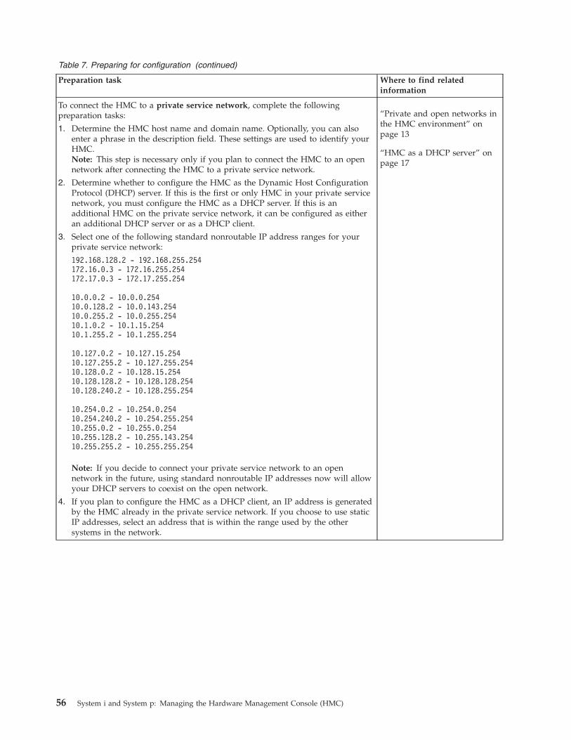
Table 7. Preparing for configuration (continued)
Preparation task Where to find relatedinformation
To connect the HMC to a private service network, complete the followingpreparation tasks:
1. Determine the HMC host name and domain name. Optionally, you can alsoenter a phrase in the description field. These settings are used to identify yourHMC.Note: This step is necessary only if you plan to connect the HMC to an opennetwork after connecting the HMC to a private service network.
2. Determine whether to configure the HMC as the Dynamic Host ConfigurationProtocol (DHCP) server. If this is the first or only HMC in your private servicenetwork, you must configure the HMC as a DHCP server. If this is anadditional HMC on the private service network, it can be configured as eitheran additional DHCP server or as a DHCP client.
3. Select one of the following standard nonroutable IP address ranges for yourprivate service network:
192.168.128.2 - 192.168.255.254172.16.0.3 - 172.16.255.254172.17.0.3 - 172.17.255.254
10.0.0.2 - 10.0.0.25410.0.128.2 - 10.0.143.25410.0.255.2 - 10.0.255.25410.1.0.2 - 10.1.15.25410.1.255.2 - 10.1.255.254
10.127.0.2 - 10.127.15.25410.127.255.2 - 10.127.255.25410.128.0.2 - 10.128.15.25410.128.128.2 - 10.128.128.25410.128.240.2 - 10.128.255.254
10.254.0.2 - 10.254.0.25410.254.240.2 - 10.254.255.25410.255.0.2 - 10.255.0.25410.255.128.2 - 10.255.143.25410.255.255.2 - 10.255.255.254
Note: If you decide to connect your private service network to an opennetwork in the future, using standard nonroutable IP addresses now will allowyour DHCP servers to coexist on the open network.
4. If you plan to configure the HMC as a DHCP client, an IP address is generatedby the HMC already in the private service network. If you choose to use staticIP addresses, select an address that is within the range used by the othersystems in the network.
“Private and open networks inthe HMC environment” onpage 13
“HMC as a DHCP server” onpage 17
56 System i and System p: Managing the Hardware Management Console (HMC)
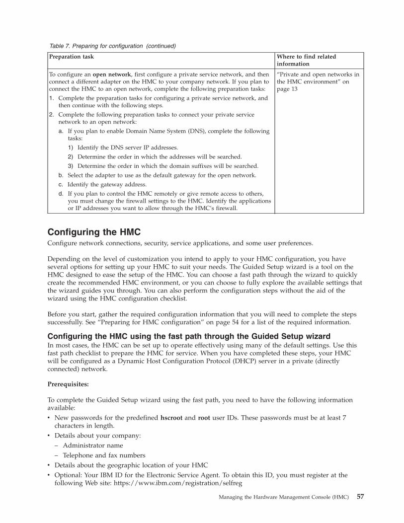
Table 7. Preparing for configuration (continued)
Preparation task Where to find relatedinformation
To configure an open network, first configure a private service network, and thenconnect a different adapter on the HMC to your company network. If you plan toconnect the HMC to an open network, complete the following preparation tasks:
1. Complete the preparation tasks for configuring a private service network, andthen continue with the following steps.
2. Complete the following preparation tasks to connect your private servicenetwork to an open network:
a. If you plan to enable Domain Name System (DNS), complete the followingtasks:
1) Identify the DNS server IP addresses.
2) Determine the order in which the addresses will be searched.
3) Determine the order in which the domain suffixes will be searched.
b. Select the adapter to use as the default gateway for the open network.
c. Identify the gateway address.
d. If you plan to control the HMC remotely or give remote access to others,you must change the firewall settings to the HMC. Identify the applicationsor IP addresses you want to allow through the HMC’s firewall.
“Private and open networks inthe HMC environment” onpage 13
Configuring the HMCConfigure network connections, security, service applications, and some user preferences.
Depending on the level of customization you intend to apply to your HMC configuration, you haveseveral options for setting up your HMC to suit your needs. The Guided Setup wizard is a tool on theHMC designed to ease the setup of the HMC. You can choose a fast path through the wizard to quicklycreate the recommended HMC environment, or you can choose to fully explore the available settings thatthe wizard guides you through. You can also perform the configuration steps without the aid of thewizard using the HMC configuration checklist.
Before you start, gather the required configuration information that you will need to complete the stepssuccessfully. See “Preparing for HMC configuration” on page 54 for a list of the required information.
Configuring the HMC using the fast path through the Guided Setup wizardIn most cases, the HMC can be set up to operate effectively using many of the default settings. Use thisfast path checklist to prepare the HMC for service. When you have completed these steps, your HMCwill be configured as a Dynamic Host Configuration Protocol (DHCP) server in a private (directlyconnected) network.
Prerequisites:
To complete the Guided Setup wizard using the fast path, you need to have the following informationavailable:v New passwords for the predefined hscroot and root user IDs. These passwords must be at least 7
characters in length.v Details about your company:
– Administrator name– Telephone and fax numbers
v Details about the geographic location of your HMCv Optional: Your IBM ID for the Electronic Service Agent. To obtain this ID, you must register at the
following Web site: https://www.ibm.com/registration/selfreg
Managing the Hardware Management Console (HMC) 57

v Optional: SMTP server and e-mail addresses for problem notification.v New passwords for the managed system, the Advanced System Management general user ID, and the
Advanced System Management administrator user ID.
Start the fast path through the Guided Setup wizard:
To use the fast path to configure your HMC, follow these steps:
Start the HMC and passwords:
1. Ensure that the managed system is not connected to a power source. For rack-mounted HMCs, thismeans that the only device plugged into the power distribution bus (PDB) before you plug in themain power supply is the HMC. (See “Cabling the HMC” on page 22 if you are not sure.) If this is asecond HMC that is connected to the same managed system, the managed system can be connectedto a power source.
2. Turn on the HMC by pressing the power button.3. Wait for the HMC to automatically select the default language and locale preference after 30 seconds.4. To continue, accept the Hardware Management Console license agreements. If you decline the
Hardware Management Console license agreements, you cannot complete the HMC configuration.5. Log in to the HMC:
v ID: hscrootv Password: abc123
The Guided Setup Wizard opens.6. Click OK on the Guided Setup entry window.7. Click Next on the Welcome window.8. Verify and change, if necessary, the time, date, and time zone settings. Click Next.9. Change the hscroot password:
a. Enter the new password twice. The password must be at least 7 characters in length.b. Click Next.
10. Change the root password:a. Enter the new password twice. The password must be at least 7 characters in length.b. Click Next.c. Click Next again.
11. Click Next on the Next Steps summary window.
Configuring network settings:
1. On the second Configure Network Settings window, select the LAN adapter labeled eth0. Click Next.2. On the LAN adapter speed window, click Next.3. On the Configure (LAN adapter name) window, click Next.4. On the second Configure (LAN adapter name) window, select private service network. Click Next.5. On the third Configure (LAN adapter name) window, select Yes, enable the HMC as a DHCP server.
Click Next.6. On the Configure Network Settings window, select No. (You can configure any remaining LAN
adapters later.) Click Next.7. Type the host name and domain name you want to use.8. Click Next on the Next Steps summary window.
Configuring connectivity to your service provider:
1. On the Specify Contact Information window, type the contact information for the administrator ofyour HMC. Click Next.
58 System i and System p: Managing the Hardware Management Console (HMC)
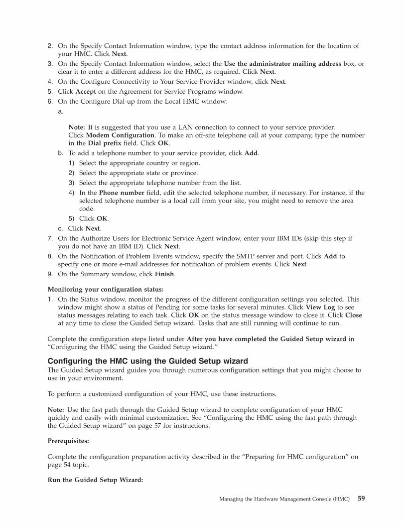
2. On the Specify Contact Information window, type the contact address information for the location ofyour HMC. Click Next.
3. On the Specify Contact Information window, select the Use the administrator mailing address box, orclear it to enter a different address for the HMC, as required. Click Next.
4. On the Configure Connectivity to Your Service Provider window, click Next.5. Click Accept on the Agreement for Service Programs window.6. On the Configure Dial-up from the Local HMC window:
a.
Note: It is suggested that you use a LAN connection to connect to your service provider.Click Modem Configuration. To make an off-site telephone call at your company, type the numberin the Dial prefix field. Click OK.
b. To add a telephone number to your service provider, click Add.1) Select the appropriate country or region.2) Select the appropriate state or province.3) Select the appropriate telephone number from the list.4) In the Phone number field, edit the selected telephone number, if necessary. For instance, if the
selected telephone number is a local call from your site, you might need to remove the areacode.
5) Click OK.c. Click Next.
7. On the Authorize Users for Electronic Service Agent window, enter your IBM IDs (skip this step ifyou do not have an IBM ID). Click Next.
8. On the Notification of Problem Events window, specify the SMTP server and port. Click Add tospecify one or more e-mail addresses for notification of problem events. Click Next.
9. On the Summary window, click Finish.
Monitoring your configuration status:
1. On the Status window, monitor the progress of the different configuration settings you selected. Thiswindow might show a status of Pending for some tasks for several minutes. Click View Log to seestatus messages relating to each task. Click OK on the status message window to close it. Click Closeat any time to close the Guided Setup wizard. Tasks that are still running will continue to run.
Complete the configuration steps listed under After you have completed the Guided Setup wizard in“Configuring the HMC using the Guided Setup wizard.”
Configuring the HMC using the Guided Setup wizardThe Guided Setup wizard guides you through numerous configuration settings that you might choose touse in your environment.
To perform a customized configuration of your HMC, use these instructions.
Note: Use the fast path through the Guided Setup wizard to complete configuration of your HMCquickly and easily with minimal customization. See “Configuring the HMC using the fast path throughthe Guided Setup wizard” on page 57 for instructions.
Prerequisites:
Complete the configuration preparation activity described in the “Preparing for HMC configuration” onpage 54 topic.
Run the Guided Setup Wizard:
Managing the Hardware Management Console (HMC) 59

Use the following instructions to configure your HMC using the Guided Setup wizard.
Note: If you are connecting the HMC to the model 9118-575 server or the 590 or 595 managed servers,you must configure the HMC in a private DHCP network using the eth0 Ethernet connection.1. Ensure that the managed system is not connected to a power source.2. Start the Guided Setup wizard:
a. Turn on the HMC by pressing the power button.b. If English is your language preference, continue with step 2e.c. If your language preference is a language other than English, type the number 2 when you are
prompted to change the locale.
Note:
1) This prompt times out in 30 seconds if you do not act.2) If your numeric keypad does not work, use the numeric keys instead.
d. Select the locale you want to display from the list in the Locale Selection window, and click OK.The locale identifies the language that the HMC interface displays.
e. Log in to the HMC using the following default user ID and password:ID: hscrootPassword: abc123
You will be prompted later to provide a new 7-character password for this ID.f. To continue, accept the Hardware Management Console license agreements. If you decline the
license agreement, you cannot complete the HMC configuration.g. When the Guided Setup wizard is displayed, complete the wizard to configure the HMC. If the
Guided Setup wizard is not displayed, you can access it manually from the HMC interface. See“Starting the Guided Setup wizard using the HMC interface” on page 61.
After you have completed the Guided Setup Wizard:
1. After you have completed the Guided Setup wizard, complete the following tasks:a. Connect the managed system to a power source. The managed system will then power on its
service processor. After the service processor is powered on, proceed to the next step. This processwill take 3 to 5 minutes. The following sequence of events signals that power has been applied tothe service processor (with the exception of the model 9118-575 server and the 590 and 595servers):1) Progress indicators, also referred to as checkpoints, appear on the control panel display while
the system is being started. The display might appear blank for a few moments during thissequence.
2) When the service processor has completed its power-on sequence, the green power-on lightblinks slowly and the output on the control panel is similar to the following:01 N V=F
T
b. Choose from the following options:v If you are using an HMC Version 6 or earlier, continue with step 1c.v If you are using a an HMC Version 7 or later, continue with step 1d.
c. Click Server and Partitions > Server management to view the status of your managed system.(For the model 9118-575 server and the 590 and 595 servers, also click Server and Partitions >Frame management to view the status of the frame.) It may take a few minutes for the status todisplay. Continue with step 1e on page 61.
d. Click Systems Management> Servers and Systems Management to view the status of yourmanaged system. (For servers that support frames, click Systems Management> Servers and
60 System i and System p: Managing the Hardware Management Console (HMC)
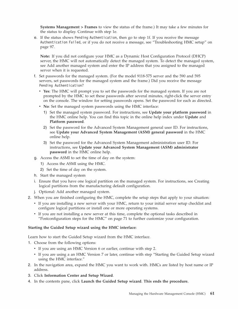
Systems Management > Frames to view the status of the frame.) It may take a few minutes forthe status to display. Continue with step 1e.
e. If the status shows Pending Authentication, then go to step 1f. If you receive the messageAuthentication Failed, or if you do not receive a message, see “Troubleshooting HMC setup” onpage 97.
Note: If you did not configure your HMC as a Dynamic Host Configuration Protocol (DHCP)server, the HMC will not automatically detect the managed system. To detect the managed system,see Add another managed system and enter the IP address that you assigned to the managedserver when it is requested.
f. Set passwords for the managed system. (For the model 9118-575 server and the 590 and 595servers, set passwords for the managed system and the frame.) Did you receive the messagePending Authentication?v Yes: The HMC will prompt you to set the passwords for the managed system. If you are not
prompted by the HMC to set these passwords after several minutes, right-click the server entryon the console. The window for setting passwords opens. Set the password for each as directed.
v No: Set the managed system passwords using the HMC interface:1) Set the managed system password. For instructions, see Update your platform password in
the HMC online help. You can find this topic in the online help index under Update andPlatform password.
2) Set the password for the Advanced System Management general user ID. For instructions,see Update your Advanced System Management (ASM) general password in the HMConline help.
3) Set the password for the Advanced System Management administration user ID. Forinstructions, see Update your Advanced System Management (ASM) administratorpassword in the HMC online help.
g. Access the ASMI to set the time of day on the system:1) Access the ASMI using the HMC.2) Set the time of day on the system.
h. Start the managed systemi. Ensure that you have one logical partition on the managed system. For instructions, see Creating
logical partitions from the manufacturing default configuration.j. Optional: Add another managed system.
2. When you are finished configuring the HMC, complete the setup steps that apply to your situation:v If you are installing a new server with your HMC, return to your initial server setup checklist and
configure logical partitions or install one or more operating systems.v If you are not installing a new server at this time, complete the optional tasks described in
“Postconfiguration steps for the HMC” on page 71 to further customize your configuration.
Starting the Guided Setup wizard using the HMC interface:
Learn how to start the Guided Setup wizard from the HMC interface.1. Choose from the following options:
v If you are using an HMC Version 6 or earlier, continue with step 2.v If you are using a an HMC Version 7 or later, continue with step “Starting the Guided Setup wizard
using the HMC interface.”2. In the navigation area, expand the HMC you want to work with. HMCs are listed by host name or IP
address.3. Click Information Center and Setup Wizard.4. In the contents pane, click Launch the Guided Setup wizard. This ends the procedure.
Managing the Hardware Management Console (HMC) 61
Configuring the HMC using the HMC configuration checklistThe HMC configuration checklist provides a complete list of all HMC configuration tasks, guiding youthrough the process of configuring your HMC. Choose this option if you prefer not to use the GuidedSetup wizard.
Complete the following checklist to successfully set up your HMC. You must restart your HMC for theconfiguration settings to take effect, so you might want to print this checklist and keep it with you as youconfigure your HMC.
This information contains references to tasks that are not included in this document. You can access theIBM Systems Hardware Information Center on the HMC or on the Web. On the HMC, the informationcenter is in the Information Center and Setup Wizard folder. On the Web, the information center is athttp://www.ibm.com/server/library/infocenter. Select a continent, your language preference, andhardware.
Prerequisites
Before you begin this checklist, be sure to complete the configuration preparation activity described in“Preparing for HMC configuration” on page 54.
HMC configuration checklist__ Start the HMC. For more information, see “Starting the HMC” on page 79.__ If you have not yet done so, get HMC fixes and update your HMC’s machine code to the latest level. Return to
this checklist when you have completed this step. Refer to get HMC fixes or .__ Set the date and time.__ Change predefined passwords. For more information, see Change predefined passwords.__ For more information about creating additional HMC users, see Create additional users and return to this
checklist when you have completed this step.__ Configure network connections:
__ To configure LAN adapters, follow these steps (perform each task for each LAN adapter). For moreinformation about configuring LAN adapters, see “Configuring LAN adapters” on page 64.Note: If you are connecting the HMC to the model 9118-575 server or the 590 or 595 managed servers, youmust configure the HMC in a private DHCP network using the eth0 Ethernet connection.__ Set the media speed. For more information about setting the media speed, see “Setting the media
speed” on page 64.__ Select the network type. For more information about how to set the network type, see “Selecting a
private or open network” on page 65.__ Unless the HMC you are setting up is an additional local HMC in your private service network or a
remote HMC in your private or open network, configure the HMC as a Dynamic Host ConfigurationProtocol (DHCP) server. For more information, see “Configuring the HMC as a DHCP server” on page65.
__ If the HMC you are setting up is an additional local HMC in your private service network or a remoteHMC in your private or open network, set the IP address. For more information, see “Setting the IPaddress” on page 68.
__ If you selected the open network, change your HMC firewall settings. For more information, see“Changing HMC firewall settings” on page 68.
__ If you are using an open network and a fixed IP address, set identification information. For moreinformation, see “Setting identification information” on page 69.
__ If you are using an open network and a fixed IP address, configure a routing entry as the default gateway.For more information, see “Configuring a routing entry as the default gateway” on page 69.
__ If you are using an open network and a fixed IP address, configure domain name services. For moreinformation, see “Configuring domain name services” on page 70.
__ If you are are using a fixed IP address and have DNS enabled, configure domain suffixes. For moreinformation, see “Configuring domain suffixes” on page 70.
__ Set up your server to connect to service and support and return to this checklist when you have completed thisstep. Configure your server to connect to IBM service and support and return to this checklist when you havecompleted this step.
62 System i and System p: Managing the Hardware Management Console (HMC)

HMC configuration checklist__ Connect the managed system to a power source. If you receive the message Authentication Pending, continue
with the next step in this checklist.
If you receive the message Authentication Failed, or you do not receive a message, see “Troubleshooting HMCsetup” on page 97.
__ Set passwords for the managed system:__ If you receive the message Authentication Pending, the HMC prompts you to set the passwords for the
managed system.__ If you did not receive the message Authentication Pending, complete the following steps to set the
passwords for the managed system. (For the model 9118-575 server and the 590 and 595 servers, setpasswords for the managed system and the frame.)__ Set the managed system password. For instructions, see Update your platform password in the HMC
online help.__ Set the password for the Advanced System Management general user ID. For instructions, see Update
your Advanced System Management (ASM) general password in the HMC online help.__ Set the password for the Advanced System Management administration user ID. For instructions, see
Update your Advanced System Management (ASM) administrator password in the HMC onlinehelp.
__ Access the ASMI to set the time of day on the system:__ Access the ASMI using the HMC.__ Set the time of day on the system.
__ Start the managed system and return to this checklist when you have completed this step.__ Ensure that you have one logical partition on the managed system. For instructions, see Creating logical
partitions from the manufacturing default configuration.__ Optional: Add another managed system and return to this checklist when you have completed this step.__ If you are installing a new server with your HMC, configure the logical partitions and install the operating
system.
Changing the predefined passwords for hscroot and root user IDs:
It is essential to your system’s security that you changing all predefined passwords immediately. Learnhow to change these predefined passwords.
. For more information about why you should change these predefined passwords, see predefinedpasswords.1. Choose from the following options:
v If you are using an HMC Version 6 or earlier, continue with step 2.v If you are using a an HMC Version 7 or later, continue with step 3 on page 64.
2. Perform the following steps:a. In the navigation area, expand the HMC that you want to work with. HMCs are listed by host
name or IP address.b. Expand HMC Management.c. Click HMC Users
d. In the contents pane, click Manage HMC users, roles, and access.e. Click the User icon.f. Right-click the hscroot icon to change the hscroot password or the root icon to change the root
password.g. Select Change Password.h. Type the new password in the first field. The password must be a minimum of 7 characters in
length.i. Confirm the new password by typing it again in the Retype new password field.
Managing the Hardware Management Console (HMC) 63
3. Perform the following steps:a. In the Navigation area, click HMC Management.
b. In the Work area, click Change user profiles and access. The User Profiles window opens.c. Select hscroot to change the hscroot password or root to change the root password.d. Select User > Modify.e. Type the new password in the first field. The password must be a minimum of 7 characters in
length.f. Confirm the new password by typing it again in the Confirm password field.g. Click OK.
Configuring network connections:
Configure network connections to allow the HMC to talk to managed systems or logical partitions. Setthe identification information, configure domain name services, and configure the LAN adapters.
Note: If you are using both a virtual Ethernet and network address translation (NAT) in your networksetup, the partition and the HMC might experience communications problems.
To configure LAN adapters, complete the following tasks for each LAN adapter:1. “Setting the media speed.”2. “Selecting a private or open network” on page 65.3. Unless the HMC you are setting up is an additional local HMC in your private service network or a
remote HMC in your private or open network, see “Configuring the HMC as a DHCP server” onpage 65.
4. If you have configured your HMC as a DHCP server, see “Verifying that your HMC DHCP privatenetwork is configured correctly” on page 66.
5. If the HMC you are setting up is an additional local HMC in your private service network or aremote HMC in your private or open network, see “Setting the IP address” on page 68.
6. If you selected the open network, see “Configuring a routing entry as the default gateway” on page69.
7. If you selected the open network, see “Changing HMC firewall settings” on page 68.
Configuring LAN adapters:
You can use the HMC to configure attached LAN adapters.
To configure LAN adapters, complete the following tasks for each LAN adapter:1. Set the media speed. For more information, see Set the media speed.2. Select the network type. For more information, see Select the network type.3. Unless the HMC you are setting up is an additional local HMC in your private service network or a
remote HMC in your private or open network, see Configuring the HMC as a DHCP server.4. If the HMC you are setting up is an additional local HMC in your private service network or a
remote HMC in your private or open network, see Setting the IP address.5. If you selected the open network, see Configuring a routing entry as the default gateway and
Changing HMC firewall settings.
Setting the media speed:
Learn how to specify the media speed and duplex mode of the Ethernet adapter.1. Choose from the following options:
v If you are using an HMC Version 6 or earlier, continue with step 2 on page 65.
64 System i and System p: Managing the Hardware Management Console (HMC)
v If you are using a an HMC Version 7 or later, continue with step 3.2. Perform the following steps:
a. In the navigation area, expand the HMC that you want to work with. HMCs are listed byhostname or IP address.
b. Expand HMC Management.c. Click HMC Configuration.d. Continue with step 4
3. In the Navigation area, click HMC Management.4. Click Change network settings.5. Click the LAN Adapters tab.6. Select the LAN adapter you want to work with and click Details.7. Click the Lan Adapter tab.8. In the Local area network information section, select the media speed.9. Click OK.
Selecting a private or open network:
A private service network consists of the HMC and the managed systems. A private service network isrestricted to consoles and the systems they manage, and is separate from your company network. Anopen network consists of your private service network and your company network. An open networkmight contain network endpoints in addition to consoles and managed systems, and might span acrossmultiple subnets and network devices.
To select a private or public network, do the following:1. Choose from the following options:
v If you are using an HMC Version 6 or earlier, continue with step 2.v If you are using a an HMC Version 7 or later, continue with step 3.
2. Perform the following steps:a. In the navigation area, expand the HMC that you want to work with. HMCs are listed by
hostname or IP address.b. Expand HMC Management.c. Click HMC Configuration.d. Continue with step 4.
3. In the Navigation area, click HMC Management.4. Click Change network settings.5. Click the LAN Adapters tab.6. Select the LAN adapter that you want to work with and click Details.7. Click the Lan Adapter tab.8. In the Local area network information page, select Private or Open.9. Click OK.
Configuring the HMC as a DHCP server:
Dynamic Host Configuration Protocol (DHCP) provides an automated method for dynamic clientconfiguration.
Clients that are enabled for DHCP automatically obtain their own IP address and configurationparameters from the server. In a private service network, configure your first or only HMC as a DHCPserver. The HMC then provides nonroutable IP addresses to its managed systems. This situation allows
Managing the Hardware Management Console (HMC) 65
the HMC to coexist with other DHCP servers in your company network when you connect your privateservice network to an open network. For more information, see “HMC as a DHCP server” on page 17.
Note: If you are connecting the HMC to the model 9118-575 server or the 590 or 595 managed servers,you must configure the HMC in a private DHCP network using the eth0 Ethernet connection.
To configure the HMC as a DHCP server, do the following:1. Choose from the following options:
v If you are using an HMC Version 6 or earlier, continue with step 2.v If you are using a an HMC Version 7 or later, continue with step 3.
2.
a. In the navigation area, expand the HMC that you want to work with. HMCs are listed byhostname or IP address.
b. Expand HMC Management.c. Click HMC Configuration
d. In the contents pane, click Customize network settings.e. Continue with step 5.
3. In the Navigation area, click HMC Management.4. In the Work area, click Change network settings. The Customize Network Settings window opens.5. Click the LAN Adapters tab.6. Select the LAN adapter that you want to work with and click Details.7. Click the Lan Adapter tab.8. In the DHCP Server section, check Enable DHCP Server to enable the HMC as a DHCP server.
Note: You can only configure the HMC to be a DHCP server on a private network. If you use anopen network, the you do not have the option to check the Enable DHCP box.
9. Enter the address range of the DHCP server.10. Click OK.
If you configured your HMC to be a DHCP server on a private network, you must verify that your HMCDHCP private network is configured correctly. For information about connecting your HMC to a privatenetwork, see “Selecting a private or open network” on page 65. To verify that your HMC DHCP privatenetwork is configured correctly, see “Verifying that your HMC DHCP private network is configuredcorrectly.”
Verifying that your HMC DHCP private network is configured correctly:
This section applies to all DHCP-managed managed systems. Read this article to learn how to verify thatyour HMC DHCP private network is configured correctly.
The following systems require that the HMC is configured as a DHCP server on a private network:v IBM System p5® 575v IBM eServer p590v IBM eServer p595v IBM eServer i595
If your HMC is configured as a DHCP server on a private network and is not communicating correctlywith the managed system, or you have recently modified your network configuration (moved a managedsystem, replaced an HMC, or added a second HMC), use the following instructions to determine if yourDHCP-managed private network is configured correctly.
66 System i and System p: Managing the Hardware Management Console (HMC)
Note: If your HMC is set up as a DHCP server on a private network, do not use the static IP commandsmksysconn and rmsysconn to change HMC connection settings. These commands are intended for use ona public network only, where the HMC is not set up as DHCP server and managed servers use static IPaddresses.
If a system administrator previously assigned an IP address to the system through a manually executedstatic IP command, Support must remove the manual connection and establish a DHCP connectionbetween the HMC and the server. This section describes how to identify any manually assigned IPaddresses so that an authorized service provider can remove them.
To identify a manually assigned IP address so that your HMC can communicate correctly with yourmanaged systems, you must perform the following high-level tasks. Detailed step-by-step taskdescriptions of how to perform these tasks are specified below.1. Identify the configured HMC IP connection addresses and compare them to the list of IP addresses
assigned by the DHCP server.2. Identify the HMC IP connection addresses that have been correctly assigned through the DHCP
server, for which no further action is required.3. Identify any manually configured HMC IP connection addresses that DHCP did not assign and that
need to be corrected by support.
To identify manually assigned IP addresses when the HMC is configured as a DHCP server, do thefollowing1. Create a list of all of the configured HMC IP connections. On the HMC command line, type the
following command:lssysconn -r all
This command displays the following information for service processors and Bulk Power Cards(BPCs) on the network for which the HMC has configured IP connection:element type, MTMS, IP address(es), connection state
2. Make a note of all IP addresses that are displayed. You will need these addresses later.3. Display a list of the DHCP IP addresses that have been assigned. To do this, type the following HMC
command:lshmc -n -F clients
The output of this command lists all IP addresses that have been assigned by the HMC’s DHCPserver.
4. Make a note of all IP addresses that are listed in the output.5. Compare the lssysconn and lshmc lists. If an IP address is displayed in the output for both the lshmc
-n -F clients and lssysconn -r all commands, the IP address was assigned by the HMC DHCP serverand the connection is being managed by the HMC DHCP server.
6. Remove from the list any address that is displayed in the output of the lshmc -n -F clients commandbut not displayed in the output of the lssysconn -r all command, and is not in the list of servers thatuse static IP addresses.
Note: If an IP address is displayed in the lshmc -n output and not in the lssysconn -r all output, thatIP address was assigned by the HMC DHCP server. However, it is not a current connection on theHMC. The DHCP server keeps a history of all IP address assignments in the event that the connectionis re-established. The DHCP server might also have assigned an IP address if an unknown device onthe private network requested a DHCP IP address from the HMC.
7. If the HMC is managing servers on both a private and a public network, any connections to theservice processor on the public network (not in the private network address range) must also be
Managing the Hardware Management Console (HMC) 67

identified and removed from this list. If there are no IP adresses remaining in the list that contains thelssyconn -r all output, the HMC DHCP server has assigned all of the system IP addresses, and thenetwork configuration is working correctly.
8. If there are any IP addresses not removed from the list taken from the lssysconn -r all command, thisaddress was not assigned by the HMC’s DHCP server. These IP address assignments must becorrected, so that they can be automatically reassigned by the HMC DHCP server. Contact anauthorized service provider and request that someone correct the manually assigned IP addresses thatyou have identified.
If you have followed this procedure and not all of your connections appear to be active (for example, twoconnections for each 590/595 system, one for each 575 system, and two for each frame), call anauthorized service provider for additional support.
Setting the IP address:
Learn how to set your IP address on the HMC.1. Choose from the following options:
v If you are using an HMC Version 6 or earlier, continue with step 2.v If you are using a an HMC Version 7 or later, continue with step 3.
2. Perform the following steps:a. In the navigation area, expand the HMC that you want to work with. HMCs are listed by
hostname or IP address.b. Expand HMC Management.c. Click HMC Configuration.d. Continue with step 4
3. In the Navigation area, click HMC Management.4. Click Change network settings.5. Click the LAN Adapters tab.6. Select the LAN adapter that you want to work with and click Details.7. Click the Lan Adapter tab.8. Select Obtain an IP address automatically or Specify an IP address.9. If you selected to specify an IP address, enter the TCP/IP interface address and the TCP/IP interface
network mask.10. Click OK.
Changing HMC firewall settings:
In an open network, a firewall is used to control outside access to your company network. The HMC alsohas a firewall on each of its Ethernet adapters. If you want to control the HMC remotely or give remoteaccess to others, modify the firewall settings of the Ethernet adapter on the HMC that is connected toyour open network.
To configure a firewall, use the following steps:1. Choose from the following options:
v If you are using an HMC Version 6 or earlier, continue with step 2.v If you are using a an HMC Version 7 or later, continue with step 3 on page 69.
2. Perform the following steps:a. In the navigation area, expand the HMC that you want to work with. HMCs are listed by
hostname or IP address.b. Expand HMC Management.
68 System i and System p: Managing the Hardware Management Console (HMC)
c. Click HMC Configuration.d. Continue with step 4.
3. In the Navigation area, click HMC Management.4. Click Change network settings.5. Click the LAN Adapters tab.6. Select the LAN adapter that you want to work with and click Details.7. Click the Firewall tab.8. Using one of the following methods, you can allow any IP address using a particular applications
through the firewall, or you can specify one or more IP addresses:v Allow any IP address using a particular application through the firewall:
a. From the top box, highlight the application.b. Click Allow Incoming. The application displays in the bottom box to signify that it has been
selected.v Specify which IP addresses to allow through the firewall:
a. From the top box, highlight an application.b. Click Allow Incoming by IP Address.c. On the Hosts Allowed window, enter the IP address and the network mask.d. Click Add and click OK.
9. Click OK.
Setting identification information:
Identification information includes the HMC’s hostname, the domain name, and the HMC’s description.
To identify your system to the network, complete the following steps:1. Choose from the following options:
v If you are using an HMC Version 6 or earlier, continue with step 2.v If you are using an HMC Version 7 or later, continue with step 3.
2. Perform the following steps:a. In the Navigation area, expand the HMC you want to work with. HMCs are listed by hostname or
IP address.b. Expand HMC Management.c. Click HMC Configuration
d. Continue with step 4.3. In the Navigation area, click HMC Management.4. Click Change network settings. The Customize Network Settings window opens.5. Click the Identification tab.6. In the Console name field, enter the HMC’s hostname.7. Enter the domain name.8. In the Computer description field, enter the HMC’s description.9. Click OK.
Configuring a routing entry as the default gateway:
Learn how to configure a routing entry as the default gateway.
To configure a routing entry as the default gateway, do the following:1. Choose from the following options:
Managing the Hardware Management Console (HMC) 69
v If you are using an HMC Version 6 or earlier, continue with step 2.2. Perform the following steps:
a. In the navigation area, expand the HMC you want to work with. HMCs are listed by hostname orIP address.
b. Expand HMC Management.c. Click HMC Configuration.d. In the contents pane, click Customize network settings.e. Continue with step 4.
3. In the Work area, click Change network settings. The Customize Network Settings window opens.4. Click the Routing tab.5. In the Default gateway information section:
a. Enter the gateway address of the routing entry you want to set as the default gateway.b. Enter the gateway device of the routing entry you want to set as the default gateway.
6. Click OK.
Configuring domain name services:
If you plan to set up an open network, configure domain name services.
Domain Name System (DNS) is a distributed database system for managing host names and theirassociated Internet Protocol (IP) addresses. Configuring domain name services includes enabling DNSand specifying the domain suffix search order.1. Choose from the following options:
v If you are using an HMC Version 6 or earlier, continue with step 2.2. In the Navigation area, expand the HMC that you want to work with. HMCs are listed by hostname
or IP address.3. Expand HMC Management.4. Click HMC Configuration. Continue with step 5.5. In the work area, click Change network settings. The Change Network Settings window opens.6. Click the Name Services tab.7. Check DNS enabled to enable DNS.
a. Specify the DNS server search order and click Add.b. Specify the domain suffix search order and click Add.
8. Click OK.
Configuring domain suffixes:
The list of domain suffixes is used to resolve an IP address starting with the first entry in the list.
The domain suffix is a string appended to a host name that is used to help resolve its IP address. Forexample, a host name of myname might not be resolved. However, if the string myloc.mycompany.com is anelement in the domain suffix table, then there will be an attempt to resolve myname.mloc.mycompany.comalso.
To configure a domain suffix entry, use these steps:1. In the Navigation area, click HMC Management.2. In the work area, click Change network settings. The Customize Network Settings window opens.3. Click the Name Services tab.4. Enter a string to be used as a domain suffix entry.
70 System i and System p: Managing the Hardware Management Console (HMC)
5. Click Add to add it to the list.
Testing the connection between the HMC and the managed system:
This option enables you to verify that you are properly connected to the network.
To test network connectivity, you must be a member of one of the following roles:v super administratorv service representative
To test the connection between the HMC and the managed system, do the following:1. Choose from the following options:
v If you are using an HMC Version 6 or earlier, continue with step 2.v If you are using a an HMC Version 7 or later, continue with step 3.
2. Perform the following steps:a. In the navigation area, click the HMC Management icon.b. In the Contents area, click the HMC Configuration icon.c. Continue with step 4.
3. In the Navigation area, click HMC Management.4. Click Test Network Connectivity.5. In the Ping tab, type the host name or IP address of any system to which you want to connect. Click
Ping.6. Click OK.
To understand how the HMC can be used in a network, see “HMC network connections” on page 12.
For more information about configuring the HMC to connect to a network, see “Configuring the HMCusing the HMC configuration checklist” on page 62.
Postconfiguration steps for the HMC:
After you have installed and configured the HMC, you can back up the HMC, configure logicalpartitions, install and access operating systems using the HMC, and configure Capacity on Demand.
Optional: Postconfiguration tasks__ Back up the HMC.__ Configure logical partitions.__ Install the operating systems.__ Access the operating systems using the HMC.__ Configure Capacity on Demand.
Replacing an HMCLearn about the tasks you must perform when replacing an HMC.
If you are replacing an HMC that is set up as a DHCP server, you must first reinstall the HMC code baseby using one of the following:v The recovery media that was provided with your HMCv The recovery media that you last used to upgrade your HMC
You must also reinstall your customized HMC configuration data by using backup media.
Managing the Hardware Management Console (HMC) 71
Procedures for replacing an HMC differ, depending on which HMC version you have installed. Todetermine your HMC version, see Determining your HMC machine code version and release and thenreturn here.
These instructions assume that you have created a backup of your HMC configuration data from theHMC being replaced. For more information about backing up important HMC data, see Backing upcritical HMC data. If you do not have a backup of the HMC, these procedures are the same as thosedescribed in “Installing the HMC” on page 21.
For HMC V4.5 or earlier
1. Insert the HMC recovery media, then power on or reboot the HMC. The HMC powers on andloads from the media.
2. Press F8 to select Install/Recovery.3. Press F1 to continue. After the installation is complete, the HMC prompts you to insert the
backup media.4. Insert the backup media. When you are finished, the HMC is restored to the state that it was
in at the time that the backup was created.5. After the HMC interface has been restored, verify that your HMC DHCP private network is
configured correctly. For more information, see Verifying that your HMC DHCP privatenetwork is configured correctly.
For HMC V5.0 or later
1. Insert the HMC recovery media, then power on or reboot the HMC. The HMC powers onfrom the media and displays the Backup/Upgrade/Restore/Install panel.
2. Select Install and click Next. Wait for the installation to complete.3. Select 1 - Install additional software from media from the menu displayed to install the
second HMC recovery media.4. Remove the recovery media and insert the second media.5. Press Enter to start the installation of the second recovery media.6. After the installation is complete, remove the second recovery media, insert the backup media,
and select 1 - Restore Critical Console Data from the menu to restore data from the backupmedia. When you are finished, the HMC is restored to the state that it was in at the time thatthe backup was created.
7. After the HMC interface has been restored, verify that your HMC DHCP private network isconfigured correctly. For more information, see Verifying that your HMC DHCP privatenetwork is configured correctly.
Installing and securing the remote clientInstall the Web-based System Manager Remote Client or install the Web-based System Manager RemoteClient for Java Web Start.
You can access your Hardware Management Console (HMC) remotely by installing the remote client onyour PC. The remote client provides flexibility by allowing you to manage your system from virtuallyanywhere you have a PC. Up to five remote clients can be logged in simultaneously. There are some tasksyou cannot perform using the remote client. These tasks include determining the level of HMC code,restarting the HMC interface, and configuring System Manager Security for certificate authority orviewing overview and status information. System Manager Security ensures that the HMC can operatesecurely in client/server mode. Servers and clients communicate over the Secure Sockets Layer (SSL)protocol, which provides server authentication, data encryption, and data integrity.
To set up the remote client and secure the HMCs in your network, perform the following procedures forWeb-based System Manager Remote Client for Java Web Start or the Web-based System Manager.
72 System i and System p: Managing the Hardware Management Console (HMC)
Web-based System Manager Remote Client for Java Web Start
1. “Configuring one HMC as a certificate authority”2. “Generating private key ring files for the servers”3. “Installing private key ring files on the servers” on page 744. “Distributing the certificate authority’s public key with Web-based System Manager Remote Client for
Java Web Start” on page 745. “Viewing configuration properties” on page 766. “Configuring HMC object manager security” on page 767. “Installing the Web-based System Manager Remote Client for Java Web Start” on page 788. “Uninstalling the Web-based System Manager Remote Client for Java Web Start” on page 79
Web-based System Manager Remote Client
1. “Configuring one HMC as a certificate authority”2. “Generating private key ring files for the servers”3. “Installing private key ring files on the servers” on page 744. “Installing the Web-based System Manager Remote Client” on page 775. “Distributing the certificate authority’s public key with Web-based System Manager Remote Client”
on page 756. “Viewing configuration properties” on page 767. “Configuring HMC object manager security” on page 768. “Uninstalling the Web-based System Manager Remote Client” on page 77
To install Web-based System Manager on AIX®, see the Web-based System Manager AdministrationGuide.
Configuring one HMC as a certificate authorityThis procedure defines a system as an internal certificate authority (CA) for HMC security and creates apublic key ring file for the CA that you can distribute to all of the clients that access the servers.1. Verify that you are using a local HMC and not the Web-based System Manager Remote Client.2. Ensure that you are logged in as the hscroot user at the HMC that is being configured as the internal
CA.3. In the navigation area, expand the local HMC. It is the first HMC in the list.4. Expand System Manager Security.5. Click Certificate Authority.6. In the System Manager Certificate Authority window, click Configure this system as a System
Manager Certificate Authority. You can also select Configure from the Certificate Authority menu.7. Use the online help to guide you through completing the task.
Note: Remember the password you set for the CA private key file. You will need this password whenyou generate private key ring files for the servers.
Generating private key ring files for the serversUse the certificate authority (CA) to generate private key ring files for the servers. The private key ringfile consists of the private key and the server certificate.
Note: If the system defined as a CA will also be used in server mode, you must complete the steps forgenerating and installing private key ring files on that system.1. In the navigation area, expand the local HMC. It is the first HMC in the list.2. Expand System Manager Security.
Managing the Hardware Management Console (HMC) 73
3. Click Certificate Authority.4. In the System Manager Certificate Authority window, click Generate Servers’ Private Key Ring Files.
You can also select Generate Keys from the Certificate Authority menu.5. In the Password window, type the CA private key file password. This password was created when the
HMC was configured as the CA.6. Click OK.7. In the Generate Server’s Private Key Ring Files window, use the help information to guide you
through completing the task.8. Click OK when you are finished.
Installing private key ring files on the serversFollow these steps to correctly install private key ring files.1. Copy the server private key ring files to removable media:
a. In the navigation area, expand the local HMC. It is the first HMC in the list.b. Expand System Manager Security.c. Click Certificate Authority.d. In the System Manager Certificate Authority window, click Copy Servers’ Private Key Ring Files
to removable media. You can also select Copy Servers’ Keys from the Certificate Authority menu.e. When the Copy Server’s Private Key to removable media dialog displays, insert the media.f. Click OK to copy the servers’ private key ring files to removable media.
2. Install the private key ring file on each server. Repeat the following steps for each server for whichyou generated a private key ring file:a. In the navigation area, expand the local HMC. It is the first HMC in the list.b. Expand System Manager Security.c. Click Server Security.d. In the System Manager Server Security window, click Install the private key ring file for this
server. You can also select Install Key from the Server menu.e. In the Install Private Key Ring File window, select removable media as the source for the server
private key ring file. Insert the removable media containing the server’s key into the removablemedia drive.
f. Click OK.3. Configure the server as a secure System Manager server. Repeat the following steps for each server on
which you installed a private key ring file:a. In the navigation area, expand the local HMC. It is the first HMC in the list. HMCs are listed by
hostname or IP address.b. Expand System Manager Security.c. Click Server Security.d. In the System Manager Server Security window, click Configure this system as a Secure System
Manager server. You can also select Configure from the Server menu.e. Use the help to guide you through completing the task.
Distributing the certificate authority’s public key with Web-basedSystem Manager Remote Client for Java Web StartIf you are using the Web-based System Manager Remote Client for Java Web Start, use the followinginstructions to copy the certificate authority (CA) public key ring file (SMpubkr.zip) to each server thatyou will use to download the remote client.
74 System i and System p: Managing the Hardware Management Console (HMC)

If the system defined as a CA will also be used in server mode, you must complete the steps fordistributing the CA’s public key for that system. Although the CA public key was created on this system,it is not in the correct location for the system to be used as a server.1. On the CA system, perform the following steps to copy the CA’s public key to removable media:
a. In the navigation area, expand the local HMC. It is the first HMC in the list.b. Expand System Manager Security.c. Click Certificate Authority.d. In the System Manager Certificate Authority window, click Copy this Certificate Authority’s
Public Key Ring File to removable media. You can also select Copy out CA Public Key from theCertificate Authority menu.
e. When the Copy CA Public Key to Removable Media window opens, insert a diskette.f. Select HMC or AIX client to write the file to a tar diskette.g. Click OK to copy the public key ring file.
2. Copy a CA’s public key from diskette to each server. Repeat the following steps for each client orserver:a. In the navigation area, expand the local HMC. It is the first HMC in the list.b. Expand System Manager Security.c. Click Certificate Authority.d. In the System Manager Certificate Authority window, click Copy another Certificate Authority’s
Public Key Ring File from removable media. You can also select Copy in CA Public Key fromthe Certificate Authority menu.
e. When the Copy CA Public Key from removable media window opens, insert the removable mediathat contains the copied CA’s public key ring file.
f. Click OK to copy the public key ring file.
Distributing the certificate authority’s public key with Web-basedSystem Manager Remote ClientIf you are using the Web-based System Manager Remote Client, follow these instructions to copy theCA’s public key ring file (SM.pubkr) to the Web-based System Manager directory of each client:1. The Web-based System Manager Remote Client must be installed on the client before proceeding. If
you have not yet installed the Web-basd System Manager Remote Client, perform the steps in“Installing the Web-based System Manager Remote Client” on page 77, and then return to theseinstructions.
2. On the CA system, perform the following steps to copy the CA’s public key to removable media:a. If you plan to distribute the CA’s public key to an HMC or AIX client, ensure that the disk is a tar
media.If you plan to distribute the CA’s public key to a PC client, ensure that the media is formatted forDOS.
b. In the navigation area, expand the local HMC. It is the first HMC in the list.c. Expand System Manager Security.d. Click Certificate Authority.e. In the System Manager Certificate Authority window, click Copy this Certificate Authority’s
Public Key Ring File to removable media.f. When the Copy CA Public Key to Removable Media window opens, insert the media.g. Select the type of client or server to which you want the public key ring file to be copied:
v Select HMC or AIX client to write the file to a tar media.v Select PC client to write the file to media in DOS file format.
h. Click OK to copy the public key ring file.
Managing the Hardware Management Console (HMC) 75
3. To copy a CA’s public key from removable media to each HMC client:Repeat the following steps for each client or server:a. In the navigation area, expand the local HMC. It is the first HMC in the list.b. Expand System Manager Security.c. Click Certificate Authority.d. In the System Manager Certificate Authority window, click Copy another Certificate Authority’s
Public Key Ring File from removable media.e. When the Copy CA Public Key from Removable Media window opens, insert the diskette that
contains the copied CA’s public key ring file.f. Click OK to copy the public key ring file.
4. Distribute the CA’s public key to your Windows, Linux, or AIX remote clients using the followingsteps:Use command line or stand-alone tools to copy the CA’s public key from removable media to thecodebase directory of the remote client. The CA’s public key file must be copied in binary format. Thecodebase directory locations are:v On a Windows client: Program files\websm\codebase
v On an AIX client: /usr/websm/codebase
v On a Linux client: /opt/websm/codebase
Viewing configuration propertiesYou can view the properties of the certificate authority (CA) and of any server. The property windowsprovide read-only information for the CA and the servers.
View CA properties
1. In the navigation area, expand the local HMC. It is the first HMC in the list.2. Expand System Manager Security.3. Click Certificate Authority.4. Select Properties.5. Type the password.
View server properties
1. In the navigation area, expand the local HMC. It is the first HMC in the list.2. Expand System Manager Security.3. Click Server Security.4. Select View properties for this server from the task list.
Configuring HMC object manager securityLearn about how to configure object manager security.1. In the navigation area, expand the local HMC. It is the first HMC in the list.2. Expand System Manager Security.3. Click Object Manager Security.4. Click Configure Object Manager Security.5. Select a socket mode.6. Click OK.
If you are using the Web-based System Manager Remote Client for Java Web Start, install this productnow. See “Installing the Web-based System Manager Remote Client for Java Web Start” on page 78.
76 System i and System p: Managing the Hardware Management Console (HMC)
Installing the Web-based System Manager Remote ClientFollow these steps to successfully install the Web-based System Manager Remote Client.1. Uninstall the previous version of the Web-based System Manager Remote Client.2. Type the following address in your machine’s Web browser:
http://system name/remote_client.html
The system name is the name of the HMC you plan to access remotely.3. Enter your HMC user ID and password.4. Click InstallShield.5. Click Windows to download the setup.exe file or click Linux to download the wsmlinuxclient.exe
file.6. If you are using a Linux system, run the following command to make the wsmlinuxclient.exe file
executable:chmod 755 wsmlinuxclient.exe
7. Run the wsmlinuxclient.exe file or the setup.exe file to begin the installation process. If youencounter problems with this step, see Troubleshooting for help.
8. When the Remote Client Installer window displays, click Next to continue.9. To install using the default location, click Next. Otherwise, browse or type the desired location and
click Next. A confirmation window displays, showing you the installation location, the packagebeing installed, and the approximate size of the installation package. If any of the information shownis incorrect, click Back to make corrections.
10. Click Next to start the installation. A status window displays a message indicating the installationcompleted successfully or error messages if errors occurred during the installation.
11. Click Finish to close the window.12. Type the following address in your machine’s Web browser:
http://system name/remote_client_security.html
The system name is the name of the HMC you plan to access remotely.13. Click Windows to download the setupsec.exe file or click Linux to download the setupsecl.exe file.14. Run the setupsecl.exe file or the setupsec.exe file to begin the installation process. If you encounter
problems with this step, see Troubleshooting for help.15. When the Remote Client Security Installer window displays, click Next to continue.16. To install using the default location, click Next. Otherwise, browse or type the desired location and
click Next. A confirmation window displays, showing you the installation location, the packagebeing installed, and the approximate size of the installation package.
Note: Be sure the location you select in this step is the same location that you selected wheninstalling the remote client.
17. If any of the information shown is incorrect, click Back to make corrections. Click Next to start theinstallation. A status window displays a message indicating the installation completed successfully,or error messages if an error occurred during the installation.
18. Click Finish to close the window.
Note: To make a secure connection from the Remote Client, you must configure security on the HMCand copy the CA’s public key to the client. See Web-based System Manager Remote Client tasks.
Uninstalling the Web-based System Manager Remote ClientTo install the latest version of the Web-based System Manager Remote Client, you must uninstall anyprevious versions from your Linux or Windows PC.
Linux
Managing the Hardware Management Console (HMC) 77
1. Run the following command:installdir/_uninst/uninstall
The installdir is the name of the directory where the remote client is located.2. Run the following command:
installdir/_uninstssl/uninstallssl
The installdir is the name of the directory where your remote client is located.
Windows
Complete the following steps once to uninstall the Web-based System Manager Remote Client and againto uninstall remote client security:1. From the task bar, select Start > Settings > Control panel.2. In the Control window, double-click the Add/Remove Programs icon.3. From the list of programs on the Install/Uninstall tab, select Web-Based System Manager Remote
Client to uninstall the remote client and Remote Client Security to uninstall remote HMC clientsecurity.
Note: Earlier versions of the remote client might display as Web-based System Manager PC Clientand the remote client security as Web-based System Manager PC Client Security.
4. Click Change/Remove to start the Uninstall wizard.5. Click Next in the initial window.6. Click Next in the Confirmation window. A status window displays a message indicating that the
uninstallation completed successfully or error messages if errors occurred during the uninstallation.7. Click Finish to close the window.8. Repeat steps 1 through 7 to uninstall remote client security.
Installing the Web-based System Manager Remote Client for Java WebStartComplete the following steps to install the Web-based System Manager Remote Client for Java Web Start.1. Type the following address in your PC’s Web browser:
http://system name/remote_client.html
The system name is the name of the HMC you plan to access remotely.2. Enter your HMC user ID and password.3. From the Web-based System Manager Remote Client Selection page, click Java Web Start.4. If you currently do not have it installed, download Java Web Start.
If you do not have Java Web Start currently installed on your client, click Java Web Start forWindows for a Windows client or Java Web Start for Linux for a Linux client on the Web-basedSystem Manager Remote Client for Java Web Start Installation page to download the installationimage. Download the most recent compatible version. Click on each version to see systemrequirements.v To install on a Windows client, double-click the downloaded image to launch the installation
wizard.v To install on a Linux client, use the following command:
rpm -i ibm-linux-jre.i386.rpmexport PATH=$PATH:/opt/IBMJava2-142/jre/bincd //opt/IBMJava2-142/jre/javaws/updateSettings.sh
Note: Run the last line (/opt/IBMJava2-142/jre/javaws/updateSettings.sh) from the root directory.
78 System i and System p: Managing the Hardware Management Console (HMC)
5. Go back to the Web-based System Manager Remote Client for Java Web Start Installation page, andclick Remote Client to download the remote client to your PC.
6. Launch the Web-based System Manager Remote Client for Java Web Start using the Web-basedSystem Manager icon.
Note: If you installed the Web-based System Manager Remote Client for Java Web Start on a Linuxsystem, launch Web-based System Manager one of the following ways:v Use a virtual terminal session to launch the Web-based System Manager Remote Client for Java
Web Start:a. Open a virtual terminal session and navigate to the directory in which you installed Java Web
Start. This is usually the javaws directory.b. Launch Java Web Start by executing the javaws command.c. From the Java Web Start Application Manager, select View > Downloaded Applications.d. Select Web-based System Manager Remote Client.e. Select Application > Start Web-based System Manager to launch the remote client.
v Use the browser to launch the Web-based System Manager Remote Client for Java Web Start:a. Type the following address in your machine’s Web browser:
http://system name/remote_client.html
where system name is the name of the HMC you plan to access remotely.b. Click Java Web Start.c. Click Remote Client.
Uninstalling the Web-based System Manager Remote Client for JavaWeb StartTo uninstall the Web-based System Manager Remote Client for Java Web Start from your PC, completethe following steps:1. From the View menu in the Java Web Start Application Manager, select Downloaded Applications.2. Click the Web-based System Manager Remote Client icon.3. Click Application > Remove Application.
Working with the HMCDescribes how to perform actions that pertain to the HMC itself.
To learn more about the commands you can use to operate the HMC remotely, see Overview of HMCtasks.
To learn more about how to cluster your systems using InfiniBand, see Clustering systems usingInfiniBand (IB) hardware.
Basic operationsDescribes the basic operations that you can perform on your HMC, such as starting the HMC, changingthe language HMC language, and logging off the HMC.
This topic provides information on how to perform basic operations on your HMC:
Starting the HMCYou can long on to the HMC and choose which language you want to be displayed in the interface. Usethe default User ID hscroot and password abc123 to log on to the HMC for the first time.
Managing the Hardware Management Console (HMC) 79
To start the HMC, do the following:1. Turn on the HMC by pressing the power button.2. If English is your language preference, continue with step 5.
If your language preference is a language other than English, type the number 2 when you areprompted to change the locale.
Note: This prompt times out in 30 seconds if you do not act.3. Select the locale that you want to display from the list in the Locale Selection window, and click OK.
The locale identifies the language that the HMC interface uses.4. Click Log on and launch the Hardware Management Console web application.5. Log in to the HMC using the following default user ID and password:
ID: hscrootPassword: abc123
6. Press Enter.
Shutting down, logging off, and disconnecting the HMCLearn how to shut down, log off, and disconnect the HMC interface.
Shut down, log off, and disconnect the HMC interface.
Attention: Only use the white button on the HMC to perform a manual shutdown if the server does notrespond to any tasks performed from the console, such as shutting down the HMC.
If an operating system is open and running on a partition, and you decide to shut down, reboot, or logoff the HMC interface, the operating system continues to run without interruption.
Logging off the HMC:
1. Choose from the following options:v If you are using an HMC Version 6 or earlier, continue with step 2.v If you are using a an HMC Version 7 or later, continue with step 3.
2. Perform the following steps:a. In the main menu, click Console > Exit. At this point, you can select to save the state of the
console for the next session by selecting the check box next to the option.b. Click Exit Now.
3. Perform the following steps:a. In the main menu, click Logoff. The Choose to Logoff or Disconnect window opens.b. Click Log off, then click OK.
Changing the date and timeThe battery-operated clock keeps the date and time for the HMC. You might need to reset the consoledate and time if the battery is replaced, or if you physically move your system to a different time zone.Learn how to change the date and time for the HMC.
If you change the date and time information, the change does not affect the systems and logical partitionsthat the HMC manages.
To change the date and time for the HMC, do the following:1. Ensure that you are a member of one of the following roles:
v Super administratorv Service representativev Operator
80 System i and System p: Managing the Hardware Management Console (HMC)
v Viewer2. Choose from the following options:
v If you are using an HMC Version 6 or earlier, continue with step 3.v If you are using a an HMC Version 7 or later, continue with step 4.
3. Perform the following steps:a. In the navigation area, expand the HMC you want to work with. HMCs are listed by hostname or
IP address.b. Expand HMC Management.c. Click HMC Configuration
d. Continue with step 5.4. In the Navigation area, click HMC Management.5. In the contents pane, click Change Date and Time.6. If you select UTC in the Clock field, the time setting will adjust automatically for daylight saving
time in the time zone you select. Enter the date, time, and time zone, and click OK.
Changing the HMC interface languageDescribes how to change the interface language that you see on the HMC interface, as well as the locale
When you power on the HMC, the HMC prompts you to change the interface language and locale. Thelocale is the language in which you want the HMC to display. Changes made using this procedure affectthe language and locale for the HMC server. If you are using the remote client to connect to the HMC,the language and locale settings on your Windows operating system determine the settings that theremote client uses to display the HMC on your PC.
Any user role can change the HMC interface language.
To change the HMC interface language and locale when you power on the HMC, do the following:1. Power on the HMC.2. When you are prompted to change the language and locale, select the language and locale you want
to display. If nothing is selected within 20 seconds, the dialog exits. By default, the Exit now andprompt again for locale change option is selected. The boot continues.
3. Click OK. When the HMC completes the power-on process, the language and locale that you selectedare displayed.
To change the HMC interface language and locale using the HMC Configuration application, do thefollowing:1. In the Navigation area, click the HMC Management icon.2. In the Contents area, double-click the HMC Configuration icon.3. In the Contents area, click Change Current Language and Locale.4. In the window, select the language and locale you want to display.5. Click OK.6. Log off the HMC interface and then log in.
Configuring the HMC keyboard layoutDescribes how to configure the keyboard layout.
When you power on the HMC, the HMC prompts you to configure the keyboard layout. If you do notrespond, the HMC continues to power on, using the previous keyboard configuration. English is thedefault setting.
Any user role can change the keyboard layout.
Managing the Hardware Management Console (HMC) 81
Note: If you previously selected the Do not run this program to change keyboard layout on the nextsystem boot option and you want to change the keyboard layout again, open a restricted shell (rshterm)and use the following chhmc command:chhmc -c kbdcfg -s enable
To configure the keyboard layout when you power on the HMC, do the following:1. Power on the HMC.2. When the Keyboard Layout Configuration Screen displays, select the Change to a new keyboard
layout option. If nothing is selected within 20 seconds, the dialog exits. By default, the Do not changekeyboard layout and run this program again on the next system boot option is selected. The bootcontinues.
3. Select the desired keyboard layout from the list.4. Select the appropriate option if you want to run this program on the next system boot and press
Enter.
Viewing recent HMC activityExplains how to view recent HMC activity.
To see a log of recent HMC activity, you can view console events. Each event has an associated timestamp.
The following is a sample of the events recorded:v When a logical partition was activatedv When a system was powered onv When a logical partition was shut downv Results of a scheduled operation
To view console events, you must be a member of one of the following roles:v super administratorv service representativev operatorv product engineer
To view console events, do the following:1. In the Navigation area, click the HMC Management icon.2. In the Contents area, click the HMC Configuration icon.3. In the Contents area, select View Console Events.
Working with partition profile informationBack up, restore, initialize, and remove profile information for the logical partitions.
You can back up, restore, initialize, and remove profiles that you have created. This topic describes eachof these options.
For more information about creating profiles, see Creating new logical partitions and partition profiles.
Backing up partition profile dataDescribes how to back up profile data on the HMC.
This topic describes how to back up logical partition profile data.
To back up partition profile data, you must be a member of one of the following roles:
82 System i and System p: Managing the Hardware Management Console (HMC)
v super administratorv service representative
To back up partition profile data, do the following:1. In the Contents area, select the managed system.2. From the menu, click Selected > Profile Data > Backup.3. Type the name you want to use for this backup file.4. Click OK.
Initializing profile dataExplains how to initialize the profile data.
When you initialize profile data, you return the managed system to a state that does not have any logicalpartitions or profiles. You can perform this task in order to stabilize your managed system if the profiledata becomes corrupt.
Important: After you perform this task, any profiles that you created prior to initialization are erased. Usethis procedure only under the direction of your service provider.
To initialize profile data, your authority level must be a super administrator.
Note: You can initialize profile data only when the managed system is in the Operating or Standby stateand all the partitions are in the Not Activated state.
To initialize profile data, do the following:1. In the Contents area, select the managed system.2. From the menu, select Selected > Profile Data > Initialize.3. Click Yes.
Restoring profile dataExplains how to read the profile data from the previously backed-up file on the HMC and load this datato the managed system.
Selecting this menu item restores profile data to the HMC from a backup file stored on the HMC harddrive.
Note: This is not a concurrent procedure. When the data is restored, the managed system powers on toPartition Standby. For more information about power-on modes, see Managed system power-on modes.
To restore stored profile data on the HMC hard drive, you must be a member of one of the followingroles:v super administratorv service representative
To restore profile data, do the following:1. In the Contents area, select the managed system.2. From the menu, select Selected > Profile Data > Restore.3. Select the profile information that you want to restore from the list of backup files.4. Select a restore option.5. Click OK.
Managing the Hardware Management Console (HMC) 83
Removing profile dataExplains how to remove the previously backed-up file on the HMC.
To remove stored profile data from the HMC hard disk drive, you must be a member of one of thefollowing roles:v super administratorv service representative
To remove stored profile data, do the following:1. In the Contents area, select the managed system.2. From the menu, select Selected > Profile Data > Remove.3. Select the profile data that you want to remove.4. Click OK.
Collecting and viewing resource utilization dataThis section describes how to gather and view resource utilization information.
You can use your HMC to collect and view the types of system activities that affect partition performanceand capacity. The following are the types of events that the HMC records:v Shared processor utilization datav Any managed system change that affects data collectionv Any partition change that affects data collection
You can use this data to analyze trends and make resource adjustments.
These topics are intended for HMC users who want to collect and view resource utilization data. Formore information, click on the associated topic link:
Setting the HMC to collect resource utilization data for managed systemsUse this procedure to set the Hardware Management Console (HMC) to collect resource utilization datafor any of the managed systems that it manages.
To set the HMC to collect resource utilization data, you must be a super administrator or operator. Formore information about user roles, refer to Tasks and roles.
When you set the HMC to collect resource utilization data for a managed system, the HMC collectsutilization data for memory and processor resources (including 5250 CPW where applicable). The HMCcollects utilization data into records called events. Events are created at the following times:v At periodic intervals (hourly, daily, and monthly)v When you make system-level and partition-level state and configuration changes that affect resource
utilizationv When you start up, shut down, and change the local time on the HMC
To set the HMC to collect resource utilization data, follow these steps:1. In the navigation area, open the object with the same name as your HMC.2. Open Server and Partition.3. Select Utilization Data Management.4. In the contents area, click Change Settings for Utilization Data Collection.
84 System i and System p: Managing the Hardware Management Console (HMC)
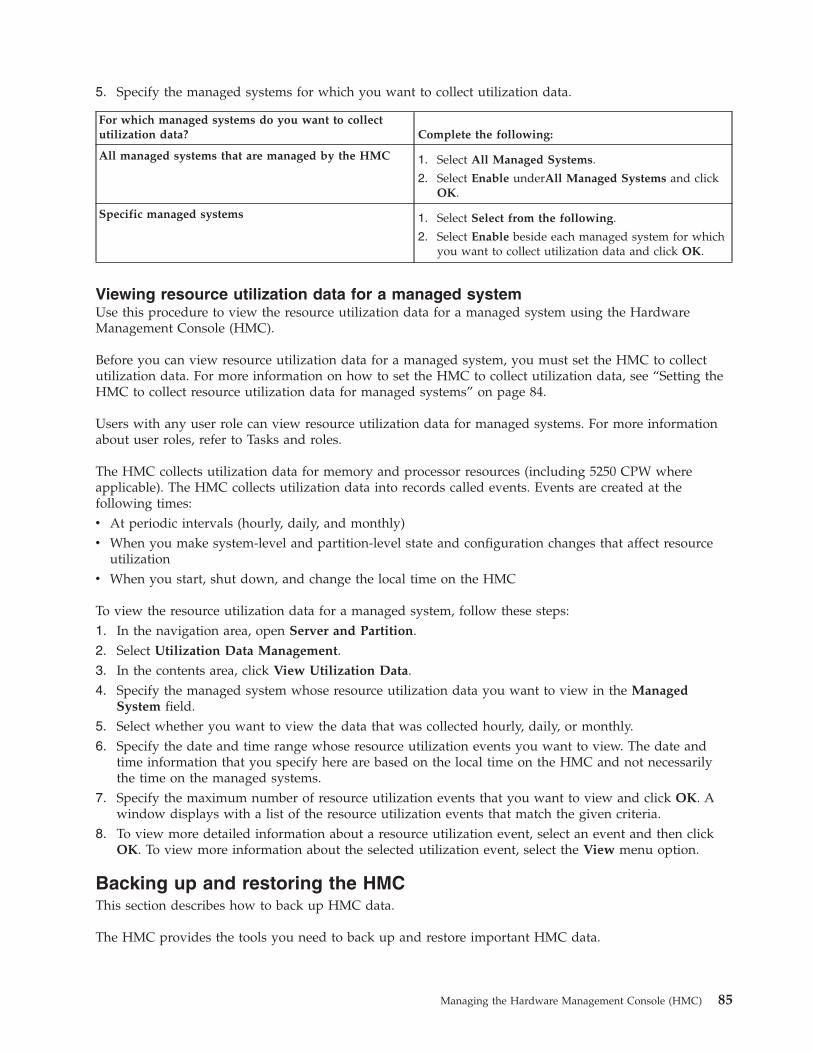
5. Specify the managed systems for which you want to collect utilization data.
For which managed systems do you want to collectutilization data? Complete the following:
All managed systems that are managed by the HMC 1. Select All Managed Systems.
2. Select Enable underAll Managed Systems and clickOK.
Specific managed systems 1. Select Select from the following.
2. Select Enable beside each managed system for whichyou want to collect utilization data and click OK.
Viewing resource utilization data for a managed systemUse this procedure to view the resource utilization data for a managed system using the HardwareManagement Console (HMC).
Before you can view resource utilization data for a managed system, you must set the HMC to collectutilization data. For more information on how to set the HMC to collect utilization data, see “Setting theHMC to collect resource utilization data for managed systems” on page 84.
Users with any user role can view resource utilization data for managed systems. For more informationabout user roles, refer to Tasks and roles.
The HMC collects utilization data for memory and processor resources (including 5250 CPW whereapplicable). The HMC collects utilization data into records called events. Events are created at thefollowing times:v At periodic intervals (hourly, daily, and monthly)v When you make system-level and partition-level state and configuration changes that affect resource
utilizationv When you start, shut down, and change the local time on the HMC
To view the resource utilization data for a managed system, follow these steps:1. In the navigation area, open Server and Partition.2. Select Utilization Data Management.3. In the contents area, click View Utilization Data.4. Specify the managed system whose resource utilization data you want to view in the Managed
System field.5. Select whether you want to view the data that was collected hourly, daily, or monthly.6. Specify the date and time range whose resource utilization events you want to view. The date and
time information that you specify here are based on the local time on the HMC and not necessarilythe time on the managed systems.
7. Specify the maximum number of resource utilization events that you want to view and click OK. Awindow displays with a list of the resource utilization events that match the given criteria.
8. To view more detailed information about a resource utilization event, select an event and then clickOK. To view more information about the selected utilization event, select the View menu option.
Backing up and restoring the HMCThis section describes how to back up HMC data.
The HMC provides the tools you need to back up and restore important HMC data.
Managing the Hardware Management Console (HMC) 85

Backing up the HMC does not back up the data on the server. For more information about backing updata on a logical partition, select the topic that matches your logical partition’s configuration:v Backing up and recovering i5/OS® dataThese topics provide instructions for backing up and restoring
i5/OS installations.v Backing up and recovering AIX logical partitionsThese topics provide instructions for backing up and
restoring AIX installations.v Backing up and recovering Linux installationsThese topics provide instructions for backing up and
restoring Linux installations.
Setting up the network interface as a startup deviceThis section describes how to enable the F12 function key to set up the network interface as a startupdevice.
On some HMC models, the F12 function key is not enabled for use when the HMC is powered on. Thesesteps enable the F12 function key so that you can specify the network interface as a startup device.
To set up the network interface as a startup device, you must be a member of one of the following roles:v super administratorv operatorv service representative
To set up the network interface as a startup device, do the following:1. Shut down and power off the HMC. For more information, see “Shutting down, logging off, and
disconnecting the HMC” on page 80.2. Power on the HMC console.3. Press F1 to start the BIOS Setup utility.4. Find and select Startup or Start Options.5. Select Startup Sequence to view the list of startup devices.6. Depending on the type of HMC (desktop or rack-mounted), use the +/- key or arrow key to make the
network interface an entry in the startup list, after the hard disk.7. If the HMC is a desktop, find and enable the Start up Device Menu prompt. This enables the F12
function key when the HMC powers on, so that you can select the network device in your startup list.For CR2 and CR3 machine types, the Planar Ethernet PXE/DHCP entry should have Planar Ethernet1 and Planar Ethernet 2.On desktop HMC machines, do the following:a. Press Esc.b. Select Devices -> Network Setup.c. Ensure that PXE Boot Agent and PXE Base code are set to Enabled. If these settings are not
enabled, networking will not occur.8. When you have finished, save the settings and exit the BIOS setup utility to restart the boot process.
You can now press F12 to select the network device as the startup device. If a DHCP server can acceptPXE requests from the HMC, and has the required files, the HMC will boot from it, then theBackup/Upgrade/Restore/Install window opens.
Beginning with HMC Version 5 Release 2.0, the chhmc command can be used on some HMC machinetypes to set the network interface as a startup device. To enable network boot on the HMC, use thefollowing command:
chhmc -c netboot -s enable
86 System i and System p: Managing the Hardware Management Console (HMC)
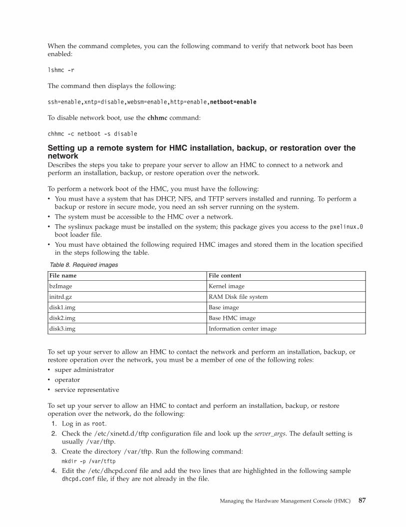
When the command completes, you can the following command to verify that network boot has beenenabled:
lshmc -r
The command then displays the following:
ssh=enable,xntp=disable,websm=enable,http=enable,netboot=enable
To disable network boot, use the chhmc command:
chhmc -c netboot -s disable
Setting up a remote system for HMC installation, backup, or restoration over thenetworkDescribes the steps you take to prepare your server to allow an HMC to connect to a network andperform an installation, backup, or restore operation over the network.
To perform a network boot of the HMC, you must have the following:v You must have a system that has DHCP, NFS, and TFTP servers installed and running. To perform a
backup or restore in secure mode, you need an ssh server running on the system.v The system must be accessible to the HMC over a network.v The syslinux package must be installed on the system; this package gives you access to the pxelinux.0
boot loader file.v You must have obtained the following required HMC images and stored them in the location specified
in the steps following the table.
Table 8. Required images
File name File content
bzImage Kernel image
initrd.gz RAM Disk file system
disk1.img Base image
disk2.img Base HMC image
disk3.img Information center image
To set up your server to allow an HMC to contact the network and perform an installation, backup, orrestore operation over the network, you must be a member of one of the following roles:v super administratorv operatorv service representative
To set up your server to allow an HMC to contact and perform an installation, backup, or restoreoperation over the network, do the following:1. Log in as root.2. Check the /etc/xinetd.d/tftp configuration file and look up the server_args. The default setting is
usually /var/tftp.3. Create the directory /var/tftp. Run the following command:
mkdir -p /var/tftp
4. Edit the /etc/dhcpd.conf file and add the two lines that are highlighted in the following sampledhcpd.conf file, if they are not already in the file.
Managing the Hardware Management Console (HMC) 87

allow bootp;allow booting;ddns-update-style none;default-lease-time 14400;max-lease-time 172800;subnet 192.168.1.0 netmask 255.255.255.0 {
range 192.168.1.100 192.168.1.200;option routers 192.168.1.1;option domain-name “somecompany.com”;option domain-name-servers 192.168.1.1;filename “pxelinux.0”;
}
This sample file specifies the range of IP addresses to be served by the DHCP server. One of the IPaddresses in this range will be assigned to the HMC when it broadcasts a request to obtain an IPaddress. The bootloader that will be used is pxlinux.0 in the /var/tftp directory. This file is part ofthe syslinux package and is usually located in the /usr/lib/syslinux directory.
5. Copy the pxelinux.0 file to the /var/tftp directory. Run the following command:cp /usr/lib/syslinux/pxelinux.0 /var/tftp/
6. Create the /var/tftp/hmc and /var/tftp/pxelinux.cfg directories by running the followingcommands: :mkdir -p /var/tftp/hmcmkdir -p /var/tftp/pxelinux.cfg
7. Copy the bzImage and initrd.gz files that you previously downloaded from your provider to the/var/tftp/hmc directory.
8. Create a directory (for example, /home/hmc) and use NFS to export this directory. If you want to usethis directory to back up the HMC over the network, you must allow write access to it.a. Run the following command to create the directory:
mkdir -p /home/hmc
b. Edit the /etc/exports file, and add the following line:/home/hmc *(ro)
To export the directory with write access, replace *(ro) with *(rw).c. Run the following command to export the directory:
exportfs -va
9. Copy the disk1.img, disk2.img and disk3.img files that you previously downloaded from yourprovider to the /home/hmc directory.
10. Create a file, named default, in the /var/tftp/pxelinux.cfg directory. This file must contain thefollowing data:default hmclabel hmc
kernel hmc/bzimageappend initrd=hmc/initrd.gz media=network
server=192.168.1.1 dir=/home/hmcmode=manual vga=0x317
This default configuration file indicates that the kernel file bzImge will be installed fromthe /var/tftp/hmc directory. The HMC uses file initrd.gz in the /var/tftp/hmc directory as theRAM disk, records the server’s IP address (192.168.1.1), and confirms that the /home/hmc/ directoryon the server contains the necessary images.
The server is now ready to accept requests from the HMC.
Backing up the entire HMC hard drive to a remote systemYou can use your HMC to back up the entire hard disk of your HMC to a remote system.
88 System i and System p: Managing the Hardware Management Console (HMC)
Your remote system must have Network File System (NFS) or Secure Shell (ssh) configured, and thisnetwork must be accessible from the HMC. To complete this task, you must shut down and reboot theHMC. Do not use the remote commands or the remote client to perform these tasks. Use an HMC.
To back up the HMC hard drive to a remote system, you must be a member of one of the following roles:v super administratorv operatorv service representative
To back up the HMC hard drive to a remote system, do the following:1. Shut down and power off the HMC. For more information, see “Shutting down, logging off, and
disconnecting the HMC” on page 80.2. Power on the HMC console with the HMC recovery media (V5R1.0 or later) in the DVD drive. If you
want to start the HMC interface from a configured network boot server, make sure the networkinterface is one of the devices in your startup sequence. To view the list of startup devices, press F12when the HMC powers on, and select the network interface from which you want to boot.
3. Select the backup option and click Next.4. Select the network interface to use for communicating with the remote server. If you are starting the
HMC by contacting a network boot server, and this server is also the remote server to which youwant to back up the data, then select the default settings. Then click Next and go to step 6. If you donot select the default settings, continue with the next step.
5. If you do not select the Default settings, you must select the network protocol to use with the selectedinterface. You can choose to obtain an IP address from a DHCP server in your network or assign astatic IP address to the selected network interface. Make your selection and click Next.
6. If you did not select the default settings, type the IP address or host name of your remote server. Thebackup file will be created using the gzip compression utility and the tar command. Specify a filewith the .tgz extension in the File on remote host field. If you have selected the default networksettings, you must use the directory setup in your network boot configuration. This information isdisplayed in the File on remote host field. After you have completed all the required information,click Next.
7. Select the method you want to use to transfer the data from your HMC to the remote server. If youchoose to encrypt the data, your remote host must have Secure Shell (SSH)server running. If youchoose to transfer the data without encryption, your remote host must have Network File Server(NFS) running, and the directory to which you want to back up data must be exported for writeaccess. Make your selection and click Next.
8. If you select to transfer the data using encryption, you must type the remote server’s user ID andpassword.
9. Verify the information you entered is correct and click Finish. When the backup completes, the HMCinterface is displayed.
If you have modified the startup sequence by pressing F1 when you powered on the HMC, you mustreboot the HMC and change the settings again. When you change the startup sequence, ensure that yourhard disk is listed in the startup sequence before the network interface.
Backing up critical HMC dataYou can back up important console information to DVD, a remote system mounted to the HMC filesystem (such as NFS), or a remote site through FTP.
Using the HMC, you can back up all important data, such as the following:v User-preference filesv User informationv HMC platform-configuration files
Managing the Hardware Management Console (HMC) 89

v HMC log filesv HMC updates through Install Corrective Service
Note: Use the archived data only in conjunction with a reinstallation of the HMC from the product CDs.For information about how to reinstall the HMC, see “Reinstalling the HMC machine code” on page 93.
The Backup function saves the HMC data stored on the HMC hard disk to DVD, a remote systemmounted to the HMC file system (such as NFS), or a remote site through FTP. Back up the HMC afteryou have made changes to the HMC or to the information associated with logical partitions.
Note: Before data can be saved to the DVD, The DVD must be formatted in the DVD-RAM format.
To back up the HMC, you must be a member of one of the following roles:v super administratorv operatorv service representative
To back up the HMC critical data, do the following:1. Choose from the following options:
v If you are using an HMC Version 6 or earlier, continue with step 2.v If you are using a an HMC Version 7 or later, continue with step 3.
2. Perform the following steps:a. In the Navigation area, click Licensed Internal Code Maintenance.b. In the Contents area, click the HMC Code Update icon.c. Continue with step 4.
3. In the Navigation area, click HMC Management.4. Select Back up HMC Data.5. Select an archive option. You can back up to DVD on the local system, back up to a mounted remote
system, or send backup data to a remote site.6. Follow the instructions on the window to back up the data.
Restoring the entire HMC hard drive using the networkDescribes how to use the network to restore the entire HMC hard drive using a previously savednetwork file.
You can use your HMC to restore your HMC hard disk from a remote system. To complete this task, youmust first have a backup copy available on your network. To learn more about backing up the entireHMC hard drive to a remote system, see “Backing up the entire HMC hard drive to a remote system” onpage 88. Your remote system must have Network File System (NFS) or Secure Shell (ssh) configured andthis network must be accessible from the HMC. To complete this task, you must shut down and rebootthe HMC. Do not use the remote commands or the remote client to perform these tasks. Use an HMChardware console.
To restore the HMC hard drive from a remote system, you must be a member of one of the followingroles:v super administratorv operatorv service representative
To restore the HMC hard drive to a remote system, do the following:
90 System i and System p: Managing the Hardware Management Console (HMC)

1. Shut down and power off the HMC. For more information, see “Shutting down, logging off, anddisconnecting the HMC” on page 80.
2. Power on the HMC console with the HMC Recovery media (V5R1.0 or later) in the DVD drive. If youwant to start from a configured network boot server, make sure the network interface is one of thedevices in your startup sequence. To view the list of startup devices, press F12 when the HMCpowers on, and select the network interface from which you want to boot. If the F12 function key isnot enabled, see “Setting up the network interface as a startup device” on page 86 to enable it.
3. Select the restore option and click Next.4. Select the network interface to use for communicating with the remote server. If you are restoring the
HMC by contacting a network boot server, and this server is also the remote server to which youwant to restore the data, then select the default settings. Press Next and go to 7.
5. If you do not select the Default settings, you must select the network protocol to use with the selectedinterface. You can choose to obtain an IP address from a DHCP server in your network, or assign astatic IP address to the selected network interface. Make your selection and click Next.
6. If you did not select the Default setting, enter the IP address or host name of your remote server andtype the backup file name in the File on remote host field. If you have selected the default networksettings, you must use the directory setup in your network boot configuration. This information isdisplayed in the File on remote host field. After you have completed all the required information,click Next.
7. Select the method you want to use to transfer the data from your remote server to your HMC. If youchoose to encrypt the data, your remote host must have secure shell server (SSH) running. If youchoose to transfer the data without encryption, your remote host must have Network File Server(NFS) running, and the directory to which you want to back up data must be exported for writeaccess. Make your selection and click Next.
8. If you want to transfer the data using encryption, type a user ID and password on the remote serverwhen you are prompted for them, and click Next.
9. Verify the information you entered is correct and click Finish. When the restore operation completes,the HMC interface displays.
If you have modified the startup sequence by pressing F1 when you powered on the HMC, you mustreboot the HMC and change the settings again. When you change the startup sequence, ensure that yourhard disk is listed before the network interface in the startup sequence.
Restoring critical HMC dataDescribes how to restore critical HMC data.
Backing up critical console data includes both backup data and corrective service data.
Restore HMC backup data only in conjunction with a reinstallation of the HMC. For information abouthow to reinstall the HMC, see “Reinstalling the HMC machine code” on page 93.
Note: For this operation, you must have one of the following:v The backup DVD mediav Access to the remote server where the archive was created by using the procedure in “Backing up
critical HMC data” on page 89
To restore the HMC data, you must be a member of one of the following roles:v super administratorv operatorv service representative
Select the data-restoration procedure based on the data archiving method used:
Managing the Hardware Management Console (HMC) 91
Restoring from DVD:
Restore data that was archived to DVD.
If the critical console data has been archived on a DVD, do the following:1. Select 1 - Restore Critical Console Data from the menu displayed at the end of the HMC
reinstallation.2. Insert the DVD containing the archived console data. On the first boot of the newly installed HMC,
the data is automatically restored.
Restoring from a remote server:
Restore data that was archived to a remote FTP or NFS sever.
If the critical console data has been archived remotely, do the following:1. Manually reconfigure network settings to enable access to the remote server after the HMC is newly
installed. For information about configuring network settings, see “Configuring the HMC” on page57.
2. In the Navigation area, click the Licensed Internal Code Maintenance icon.3. In the Contents area, click the HMC Code Update icon.4. Select Restore Remote Console Data.5. Select the type of remote restoration.6. Follow the directions on the window to restore the critical console data. The data automatically
restores from the remote server when the system is rebooted.
Scheduling and reviewing HMC backupsExplains how to schedule backups of important console information.
You can schedule a backup to DVD to occur once, or you can set up a repeating schedule. You mustprovide the time and date that you want the operation to occur. If the operation is scheduled to repeat,you must select how often you want this backup to run (hourly, daily, weekly, or monthly).
Note: Only the most-recent backup image is stored at any time on the DVD.
To schedule a backup operation, do the following:1. In the Navigation area, expand the HMC Management folder.2. In the Navigation area, click the HMC Configuration icon.3. In the Contents area, click Schedule Operations.4. From the list, select the HMC you want to back up and click OK.5. Select Options > New.6. In the Add a Scheduled Operation window, select Backup Critical Console Data and click OK.7. In the appropriate fields, enter the time and date that you want this backup to occur.8. If you want this scheduled operation to repeat, click the Repeat tab and select the intervals at which
you want the backup to repeat and press Enter.9. When you have set the backup time and date, click Save. When the Action Completed window opens,
click OK. A description of the operation displays in the Scheduled Operations window.
Saving HMC upgrade dataExplains how to save upgrade data so that you can reinstall it if the HMC must be recovered.
92 System i and System p: Managing the Hardware Management Console (HMC)
You can save the current HMC configuration in a special disk partition on the HMC. Save upgrade databefore you upgrade your HMC software to a new version or release. This action allows you to restoreHMC configuration settings after upgrading.
Note: The special disk partition can hold only one level of backup data. Every time you perform thistask, previous backup data is overwritten by the latest backup. To proceed with the upgrade after savingupgrade data, you can must place the new HMC recovery CD in the DVD drive and immediately rebootthe HMC. Any configuration changes made on the HMC after you saved the upgrade data will not besaved.
To save upgrade data, do the following:1. Expand the Licensed Internal Code Maintenance folder, then select the HMC application in the
Navigation area.2. Select the Save Upgrade Data task in the content area. An information window opens that prompts
you to select the media (hard drive or DVD).3. Select the appropriate media.4. Click Continue.5. Click OK to confirm and close the information window.
Reinstalling the HMC machine codeExplains how to reinstall the HMC machine code prior to restoring critical backup data and it describeshow to reinstall the HMC interface onto the HMC PC and install backup information.
If the HMC is not responding, you can use the recovery CD to reinstall the HMC onto the HMC PC.After you reinstall the HMC machine code, you can restore the backup data that you created to recoveryour critical console information. For information about how to restore the HMC backup data, see“Restoring critical HMC data” on page 91.
To reinstall the HMC machine code, you must be a member of one of the following roles:v super administratorv operatorv service representative
To reinstall the HMC machine code, do the following:1. Shut down and power off the HMC. For more information, see “Shutting down, logging off, and
disconnecting the HMC” on page 80.2. Power on the HMC console and insert the HMC recovery media if you want to install from it. The
HMC powers on from the media and displays the Backup/Upgrade/Restore/Install window. If youwant to install from the network and have a network boot server configured, make sure the networkinterface is one of the devices in your startup sequence. To view the list of startup devices, press F12when the HMC powers on, and select the network interface from which you want to boot. If the F12function key is not enabled, see “Setting up the network interface as a startup device” on page 86 toenable it.
3. Select the Install option, and click Next.4. Select Install from media if you are using media. If you are not installing from media, select Install
from network. Click Next.5. If you install from media, you are prompted to install the next media. Select 1 - Install additional
software from media to install the subsequent media. If you install from a network, you mustcomplete the next step.
6. After the installation is complete, select 1 - Install additional software from media from the menudisplayed to install the subsequent media.
Managing the Hardware Management Console (HMC) 93
7. Select 1 - Restore Critical Console Data from the menu to restore data from a DVD. To restore from aremote server, select 2 - Finish the Installation.
Working with users, roles, and passwordsLearn how to perform HMC user administration tasks.
The following topics provide information about HMC user administration tasks:
Creating an HMC userDescribes how to create HMC users.
You can create various users using the HMC. The hscroot, root, and hscpe user IDs are special, orreserved. The hscpe user is created for use by your service provider when performing problemdetermination.
To create a user, do the following:1. In the Navigation area, expand the HMC Management folder.2. Click the HMC users icon.3. In the Contents area, click Manage HMC Users and Access. The User Profiles window opens.4. Click User > Add. Fill in the appropriate fields and click OK.
Viewing an HMC user descriptionDescribes how to view HMC user definitions.
To view a user description, do the following:1. In the Navigation area, expand the HMC Management folder.2. Click the HMC users icon.3. In the Contents area, click Manage HMC Users and Access. The User Profiles window opens.4. Click User > Modify. The current user description is displayed.
To read about the tasks each HMC user role can perform and the commands associated with each task,see Overview of HMC tasks.
Copying HMC user informationDescribes how to copy existing user information.
To copy HMC user information, do the following:1. In the Navigation area, expand the HMC Management folder.2. Click the HMC users icon.3. In the Contents area, click Manage HMC Users and Access. The User Profiles window opens.4. Click User > Copy. Fill in the appropriate fields and click OK.
Deleting an HMC userDescribes how to delete an HMC user.
To delete a user, do the following:1. In the Navigation area, expand the HMC Management folder.2. Click the HMC users icon.3. In the Contents area, click Manage HMC Users and Access. The User Profiles window opens.4. Select the user that you want to remove.5. Click User > Remove. The Delete Item Verification window opens.
94 System i and System p: Managing the Hardware Management Console (HMC)
6. Click Yes.
Creating a customized HMC roleDescribes how to create a customized HMC role
To create a customized HMC role, do the following:1. In the Navigation area, expand the HMC Management folder.2. Click the HMC users icon.3. In the Contents area, click Manage Access Task Roles and Managed Resource Roles. The
Customized User Controls window opens.4. Click Task Roles.5. Click File > Add. The Add Role window opens.6. Fill in the appropriate fields and click OK.
Editing HMC user information and rolesDescribes how to change HMC user description.
To edit HMC user information and roles, do the following:1. In the Navigation area, expand the HMC Management folder.2. Click the HMC users icon.3. In the Contents area, click Manage HMC Users and Access. The User Profiles window opens.4. Click User > Modify. Fill in the appropriate fields and click OK.
Changing HMC user passwordsLearn how to change an existing HMC user’s password.
To change HMC user passwords, do the following:1. Choose from the following options:
v If you are using an HMC Version 6 or earlier, continue with step 2.v If you are using a an HMC Version 7 or later, continue with step 6.
2. In the Navigation area, expand the HMC Management folder.3. Click the HMC users icon.4. In the Contents area, click Manage HMC Users and Access. The User Profiles window opens.5. Click User > Modify. Type the new password and click OK. This ends the procedure.
6. In the Navigation area, click the HMC Management icon.7. In the Contents area, click Change User Profiles and Access . The User Profile window opens.8. In the User Profile window, select the user whose password you want to modify.9. Click User > Modify. Change the password information and click OK. This ends the procedure.
Using the HMC remote command lineProvides information about using the command-line interface on the HMC.
The command-line interface is useful in the following situations:v When consistent results are required. If you have to administer several managed systems, you can
achieve consistent results by using the command-line interface. The command sequence can be storedin scripts and run remotely.
v When automated operations are required. After you have developed a consistent way to manage themanaged systems, you can automate the operations by invoking the scripts from batch-processingapplications, such as the cron daemon, from other systems.
Managing the Hardware Management Console (HMC) 95
This topic provides information about using the command line interface on the HMC.
For HMC command descriptions, see the HMC commands topic.
Viewing HMC remote command informationDescribes the remote command line.
To view command information, type man and then the command name. For example, to learn more aboutthe ″Create a user for the HMC″ (mkhmcusr) command, type the following at the command line:man mkhmcusr
For HMC command descriptions, see the HMC commands topic.
Setting up secure script execution between SSH clients and the HMCDescribes how to ensure that the script executions between SSH clients and the HMC are secure.
Note: To enable scripts to run unattended between an SSH client and an HMC, the SSH protocol mustalready be installed on the client’s operating system.
HMCs typically are placed inside the machine room where managed systems are located, so you mightnot have physical access to the HMC. In this case, you can remotely access it using either the remoteclient or the remote command-line interface. This topic describes how to ensure that your scriptexecutions between SSH clients and the HMC are secure.
To enable scripts to run unattended between an SSH client and an HMC, do the following:1. In the Navigation area, select HMC Management.2. In the Navigation area, click HMC Configuration.3. In the Contents area, click Enable/Disable Remote Command Execution.4. When the window opens, select the box to enable SSH.5. Create an HMC user with one of the following roles:
v super administratorv service representative
6. On the client’s operating system, run the SSH protocol key generator. To run the SSH protocol keygenerator, do the following:a. To store the keys, create a directory named $HOME/.ssh (either RSA or DSA keys can be used).b. To generate public and private keys, run the following command:
ssh-keygen -t rsa
The following files are created in the $HOME/.ssh directory:private key: id_rsapublic key: id_rsa.pub
The write bits for both group and other are turned off. Ensure that the private key has apermission of 600.
7. On the client’s operating system, use ssh and run the mkauthkeys command to update the HMCuser’s authorized_keys2 file on the HMC by using the following command:
ssh userid@hostname "mkauthkeys --add '<the key string from $HOME/.ssh/id_dsa.pub>'"
Deleting the key from the HMC
To delete the key from the HMC, select one of the following procedures:
96 System i and System p: Managing the Hardware Management Console (HMC)
You can use this procedure to delete the key from the HMC by modifying various files:1. On the logical partition, use the scp command to copy the authorized_keys2 file from the HMC to the
logical partition, as follows:scp userid@host_name :.ssh/authorized_keys2 /tmp/mykeyfile
2. In the /tmp/mykeyfile file, remove the line that contains the key and host name of the system thatyou want to be able to run HMC commands remotely.
3. On a logical partition, use the scp command to copy the new file to the HMC:scp /tmp/mykeyfile userid@host_name ".ssh/authorized_keys2"
4. If you want to enable password prompting for all hosts that access the HMC through ssh, use the sshcommand to remove the key file from the HMC:scp userid@hostname:.ssh/authorized_keys2 authorized_keys2
5. Edit the authorized_keys2 file and remove all lines in this file, then copy it back to the HMC. Forexample:scp authorized_keys joe@somehost:.ssh/authorized_keys2
OR
You can use the command line to delete the key from the HMC by using the mkauthkeys command. Forexample:ssh userid@hostname "mkauthkeys --remove 'joe@somehost'"
Enabling and disabling HMC remote commandsExplains how to enable or disable the remote command-line interface access to the HMC using the SSHfacility.
You can enable or disable the remote command-line interface access to the HMC using the SSH facility.
To enable or disable remote commands, you must be a member of one of the following roles:v super administratorv service representative
To enable or disable remote commands, do the following:1. In the Navigation area, click the HMC Management icon.2. In the Contents area, double-click the HMC Configuration icon.3. In the Contents area, click Enable/Disable Remote Command Execution.4. Select the appropriate check box.5. Click OK.
To disable the firewall that is enabled by default, you must access the network settings on the HMC.
To disable the HMC firewall, see “Changing HMC firewall settings” on page 68.
Troubleshooting HMC setupTroubleshoot common HMC setup problems.
The following topics contain information about common problems that might occur during the setup ofthe Hardware Management Console (HMC). The topics also contain common resolutions to thoseproblems. The first topic applies to the HMC in general. The second topic applies to the remote client.
Setting up the HMC
Managing the Hardware Management Console (HMC) 97

Problem: You configured the HMC as a DHCP server, but the HMC did not automatically discover themanaged system.
Resolution: This usually indicates that the managed system was connected to a power sourcebefore the HMC was configured as the DHCP server. This situation caused the managed systemto initialize to its IP address to the default values (HMC1 as 192.168.2.147 and HMC2 as192.168.3.147) instead of waiting for an address from the HMC.
To correct the configuration on the model 9118-575 server or the 590 or 595 managed servers,contact your service provider.
To correct the configuration for the model 520, 550, and 570 managed servers, complete thefollowing tasks:1. Shut down the managed system by pressing and holding the power button.2. Remove the connection between the managed system and its power source.3. Reconnect the managed system to its power source. The HMC automatically discovers the
managed system.
If you had changed the IP address of the service processor using the ASM interface, use theappropriate procedure for your model:
Model 520
1. Shut down the managed system by pressing and holding the power button.2. Remove the connection between the managed system and its power source.3. Remove the connection between the HMC and its power source.4. Remove the service processor assembly as instructed in the Remove the model 520 service
processor assembly topic. Begin with the step following ″Disconnect the power source...″.When you have removed the service processor, proceed to the next step.
5. To reset the service processor assembly, move both service processor reset toggle switches Afrom their current position to the opposite position. See Figure 26.
6. Reinsert the service processor into the managed system. For instructions, see Replace themodel 520 service processor assembly.
7. Reconnect the HMC to its power source and start the HMC.
Figure 26. Model 520 service processor switch
98 System i and System p: Managing the Hardware Management Console (HMC)
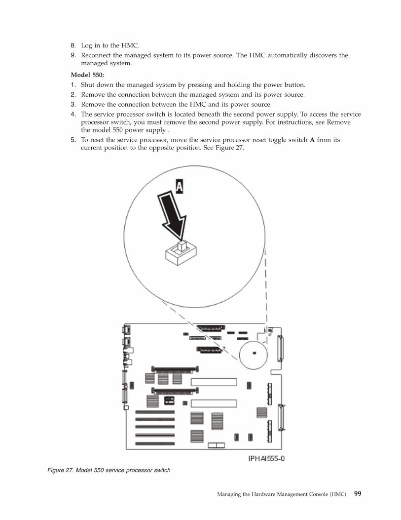
8. Log in to the HMC.9. Reconnect the managed system to its power source. The HMC automatically discovers the
managed system.
Model 550:
1. Shut down the managed system by pressing and holding the power button.2. Remove the connection between the managed system and its power source.3. Remove the connection between the HMC and its power source.4. The service processor switch is located beneath the second power supply. To access the service
processor switch, you must remove the second power supply. For instructions, see Removethe model 550 power supply .
5. To reset the service processor, move the service processor reset toggle switch A from itscurrent position to the opposite position. See Figure 27.
Figure 27. Model 550 service processor switch
Managing the Hardware Management Console (HMC) 99
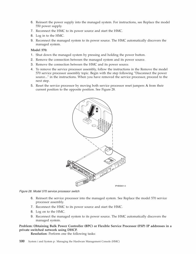
6. Reinsert the power supply into the managed system. For instructions, see Replace the model550 power supply.
7. Reconnect the HMC to its power source and start the HMC.8. Log in to the HMC.9. Reconnect the managed system to its power source. The HMC automatically discovers the
managed system.
Model 570:
1. Shut down the managed system by pressing and holding the power button.2. Remove the connection between the managed system and its power source.3. Remove the connection between the HMC and its power source.4. To remove the service processor assembly, follow the instructions in the Remove the model
570 service processor assembly topic. Begin with the step following ″Disconnect the powersource...″ in the instructions. When you have removed the service processor, proceed to thenext step.
5. Reset the service processor by moving both service processor reset jumpers A from theircurrent position to the opposite position. See Figure 28.
6. Reinsert the service processor into the managed system. See Replace the model 570 serviceprocessor assembly.
7. Reconnect the HMC to its power source and start the HMC.8. Log on to the HMC.9. Reconnect the managed system to its power source. The HMC automatically discovers the
managed system.
Problem: Obtaining Bulk Power Controller (BPC) or Flexible Service Processor (FSP) IP addresses in aprivate switched network using DHCP.
Resolution: Perform one the following tasks:
Figure 28. Model 570 service processor switch
100 System i and System p: Managing the Hardware Management Console (HMC)
v If spanning tree is enabled on the switch and you want it to remain enabled, the portfastoption must also be enabled. This setting will allow the switch to forward all packets from theport onto the LAN immediately and not check the spanning tree first.
v Disable the spanning tree on the switch for the BPC or FSP ports.
Note: Different manufacturers might use different terminology regarding these settings. Theswitch must be modified using portfast or other commands to accommodate connectivity delays.After validating the exact ports on the switch that the FSP or BPC is using, a networkadministrator must log in to the switch to make the changes to the specific ports.
Problem: After setting up the HMC, the managed system’s status is Authentication Failed.Resolution: This usually indicates that the managed system password was set prior to HMCconfiguration. In this situation, the HMC does not recognize the managed system password andcannot access the managed system. To correct this situation, update the password on themanaged system.
Installing the remote client
Problem: The wsmlinuxclient.exe or the setupsec1.exe file does not run.Resolution: Modify the permissions on the file so that you have execute permissions. To modifythe permissions, type the following command at the command prompt:chmod 755 filename
Problem: Changes do not take effect immediately after installing the Web-based System ManagerRemote Client or the remote client security on a Linux system
Resolution: Perform one of the following tasks:v Log off your current session and log in again.v Source your . /etc/profile file.
Problem: You receive an error message that you cannot complete a connectionResolution: You may receive a message that looks similar to the following:Cannot complete connection to hostname myhmc.Possible problems are:1. Host myhmc is not a valid hostname.2. Host myhmc is not currently operating or is not connected to
the network.3. Host myhmc is not running an operating system with a version of
Web-based System Manager that is compatible with your client version of Web-basedSystem Manager.
4. The time to connect could have exceeded the time limit set in the websm.cfg file(remote_timeout).
5. The inetd subsystem on host myhmc may not have been initializedon the 9090 port to start the WServer.
Additional information might be in the file /var/websm/data/wserver.log on host myhmc.
Possible solutions include the following tasks:v The following reasons are most common for this message:
– You might have exceeded the limit of remote connections allowed to the HMC you aretrying to access remotely.
– By default, the HMC uses a connect port of 9090 to handle the initial login communication.If you cannot enter your user ID and password, it means that you cannot connect to the9090 port. Often this is because too many sessions were canceled incorrectly and the 9090port is overloaded. Restart the HMC you are trying to access remotely to cancel remotesessions that were incorrectly disconnected.
v Log on to the HMC you are trying to access remotely and verify that myhmc is the host nameof that HMC.
Managing the Hardware Management Console (HMC) 101
v Locate the HMC that you are trying to access remotely and verify that it is operating andconnected to the network.
v Ensure that the version of the Web-based System Manager of the HMC you are trying to accessremotely is the same version as the Web-based System Manager Remote Client.
v The time it takes for your remote client to connect to the HMC you want to manage remotelyhas exceeded the time limit. To solve this problem, improve your connection speed. To do this,you might have to change the way in which the remote client and the HMC you want tomanage remotely are connected.
Performing a File System Check on HMC Reboot
Problem: Failed file system check (fsck) displays the following error message, ″Enter the rootpassword or hit Control-D to reboot.″
Resolution: Perform the following task:1. Type the root password.2. Run a file-system check by entering fsck file system where file system is the name of the file
system that fails the file system check. When the checking is done, a prompt window opens.3. Type reboot or press Control-D.
Related information for Capacity on DemandProduct manuals, Web sites, and information center topics contain information related to the Capacity onDemand topic. You can view or print any of the PDF files.
Manuals
v System p 650, 670, 690 Planning Guide for Capacity Upgrade on Demand (643 KB) This guideprovides information that is needed when you are planning to purchase an System p 6xx server withCapacity Upgrade on Demand (CUoD) features.
v System i On/Off Capacity on Demand Planning Guide (265 KB) This guide explains in detail allthe aspects of planning for, purchasing, and managing an System i 8xx server with On/Off Capacity onDemand.
v System i Capacity Upgrade on Demand Planning Guide (119 KB) This guide explains in detail allthe aspects of planning for, purchasing, and managing an System i 8xx server with Capacity Upgradeon Demand (CUoD).
v System i V5R1/V5R2 Planning Guide for Capacity Upgrade on Demand (96 KB) This guideexplains in detail all the aspects of planning for, purchasing, and managing an System i 8xx server withCapacity Upgrade on Demand (CUoD).
Web sites
v Resource Link™ Web site at http://www.ibm.com/servers/resourcelink - Provides the entirePOWER6 library.
v Capacity on Demand (www.ibm.com/servers/eserver/iseries/ondemand/cod) - Describes thevarious Capacity on Demand offerings.
v Capacity Upgrade on Demand for System p servers (http://www.ibm.com/servers/eserver/pseries/ondemand/cod/) - Describes Capacity Upgrade on Demand for processors and memory.
102 System i and System p: Managing the Hardware Management Console (HMC)

Other informationv Partitioning the serverv Hardware Management Consolev Electronic Service Agent
Managing the Hardware Management Console (HMC) 103

104 System i and System p: Managing the Hardware Management Console (HMC)
Appendix. Accessibility features
Accessibility features help users who have a physical disability, such as restricted mobility or limitedvision, to use information technology products successfully.
The following list includes the major accessibility features:v Keyboard-only operationv Interfaces that are commonly used by screen readersv Keys that are tactilely discernible and do not activate just by touching themv Industry-standard devices for ports and connectorsv The attachment of alternative input and output devices
IBM and accessibility
See the IBM Accessibility Center at http://www.ibm.com/able/ for more information about thecommitment that IBM has to accessibility.
© Copyright IBM Corp. 2004, 2007 105

106 System i and System p: Managing the Hardware Management Console (HMC)

Notices
This information was developed for products and services offered in the U.S.A.
The manufacturer may not offer the products, services, or features discussed in this document in othercountries. Consult the manufacturer’s representative for information on the products and servicescurrently available in your area. Any reference to the manufacturer’s product, program, or service is notintended to state or imply that only that product, program, or service may be used. Any functionallyequivalent product, program, or service that does not infringe any intellectual property right of themanufacturer may be used instead. However, it is the user’s responsibility to evaluate and verify theoperation of any product, program, or service.
The manufacturer may have patents or pending patent applications covering subject matter described inthis document. The furnishing of this document does not give you any license to these patents. You cansend license inquiries, in writing, to the manufacturer.
The following paragraph does not apply to the United Kingdom or any other country where suchprovisions are inconsistent with local law: THIS INFORMATION IS PROVIDED “AS IS” WITHOUTWARRANTY OF ANY KIND, EITHER EXPRESS OR IMPLIED, INCLUDING, BUT NOT LIMITED TO,THE IMPLIED WARRANTIES OF NON-INFRINGEMENT, MERCHANTABILITY OR FITNESS FOR APARTICULAR PURPOSE. Some states do not allow disclaimer of express or implied warranties in certaintransactions, therefore, this statement may not apply to you.
This information could include technical inaccuracies or typographical errors. Changes are periodicallymade to the information herein; these changes will be incorporated in new editions of the publication.The manufacturer may make improvements and/or changes in the product(s) and/or the program(s)described in this publication at any time without notice.
Any references in this information to Web sites not owned by the manufacturer are provided forconvenience only and do not in any manner serve as an endorsement of those Web sites. The materials atthose Web sites are not part of the materials for this product and use of those Web sites is at your ownrisk.
The manufacturer may use or distribute any of the information you supply in any way it believesappropriate without incurring any obligation to you.
Any performance data contained herein was determined in a controlled environment. Therefore, theresults obtained in other operating environments may vary significantly. Some measurements may havebeen made on development-level systems and there is no guarantee that these measurements will be thesame on generally available systems. Furthermore, some measurements may have been estimated throughextrapolation. Actual results may vary. Users of this document should verify the applicable data for theirspecific environment.
Information concerning products not produced by this manufacturer was obtained from the suppliers ofthose products, their published announcements or other publicly available sources. This manufacturer hasnot tested those products and cannot confirm the accuracy of performance, compatibility or any otherclaims related to products not produced by this manufacturer. Questions on the capabilities of productsnot produced by this manufacturer should be addressed to the suppliers of those products.
All statements regarding the manufacturer’s future direction or intent are subject to change or withdrawalwithout notice, and represent goals and objectives only.
© Copyright IBM Corp. 2004, 2007 107
The manufacturer’s prices shown are the manufacturer’s suggested retail prices, are current and aresubject to change without notice. Dealer prices may vary.
This information is for planning purposes only. The information herein is subject to change before theproducts described become available.
This information contains examples of data and reports used in daily business operations. To illustratethem as completely as possible, the examples include the names of individuals, companies, brands, andproducts. All of these names are fictitious and any similarity to the names and addresses used by anactual business enterprise is entirely coincidental.
If you are viewing this information in softcopy, the photographs and color illustrations may not appear.
The drawings and specifications contained herein shall not be reproduced in whole or in part without thewritten permission of the manufacturer.
The manufacturer has prepared this information for use with the specific machines indicated. Themanufacturer makes no representations that it is suitable for any other purpose.
The manufacturer’s computer systems contain mechanisms designed to reduce the possibility ofundetected data corruption or loss. This risk, however, cannot be eliminated. Users who experienceunplanned outages, system failures, power fluctuations or outages, or component failures must verify theaccuracy of operations performed and data saved or transmitted by the system at or near the time of theoutage or failure. In addition, users must establish procedures to ensure that there is independent dataverification before relying on such data in sensitive or critical operations. Users should periodically checkthe manufacturer’s support websites for updated information and fixes applicable to the system andrelated software.
TrademarksThe following terms are trademarks of International Business Machines Corporation in the United States,other countries, or both:
AIXeServeri5/OSOpenPowerIBMiSeriespSeriesSystem iSystem i5System pSystem p5
Microsoft, Windows, Windows NT®, and the Windows logo are trademarks of Microsoft Corporation inthe United States, other countries, or both.
Java and all Java-based trademarks are trademarks of Sun Microsystems, Inc. in the United States, othercountries, or both.
Linux is a registered trademark of Linus Torvalds in the United States, other countries, or both.
Other company, product or service names may be trademarks or service marks of others.
108 System i and System p: Managing the Hardware Management Console (HMC)

Electronic emission notices
Class A NoticesThe following Class A statements apply to the IBM System i models and IBM System p servers with theexception of those that are specifically identified as Class B.
Federal Communications Commission (FCC) statement
Note: This equipment has been tested and found to comply with the limits for a Class A digital device,pursuant to Part 15 of the FCC Rules. These limits are designed to provide reasonable protection againstharmful interference when the equipment is operated in a commercial environment. This equipmentgenerates, uses, and can radiate radio frequency energy and, if not installed and used in accordance withthe instruction manual, may cause harmful interference to radio communications. Operation of thisequipment in a residential area is likely to cause harmful interference, in which case the user will berequired to correct the interference at his own expense.
Properly shielded and grounded cables and connectors must be used in order to meet FCC emissionlimits. IBM is not responsible for any radio or television interference caused by using other thanrecommended cables and connectors or by unauthorized changes or modifications to this equipment.Unauthorized changes or modifications could void the user’s authority to operate the equipment.
This device complies with Part 15 of the FCC rules. Operation is subject to the following two conditions:(1) this device may not cause harmful interference, and (2) this device must accept any interferencereceived, including interference that may cause undesired operation.
Industry Canada Compliance Statement
This Class A digital apparatus complies with Canadian ICES-003.
Avis de conformité à la réglementation d’Industrie Canada
Cet appareil numérique de la classe A respecte est conforme à la norme NMB-003 du Canada.
European Community Compliance Statement
This product is in conformity with the protection requirements of EU Council Directive 2004/108/EC onthe approximation of the laws of the Member States relating to electromagnetic compatibility. IBM cannotaccept responsibility for any failure to satisfy the protection requirements resulting from anon-recommended modification of the product, including the fitting of non-IBM option cards.
This product has been tested and found to comply with the limits for Class A Information TechnologyEquipment according to European Standard EN 55022. The limits for Class A equipment were derived forcommercial and industrial environments to provide reasonable protection against interference withlicensed communication equipment.
European Community contact:IBM Technical RegulationsPascalstr. 100, Stuttgart, Germany 70569Tele: 0049 (0)711 785 1176Fax: 0049 (0)711 785 1283E-mail: [email protected]
Warning: This is a Class A product. In a domestic environment, this product may cause radiointerference in which case the user may be required to take adequate measures.
Notices 109

VCCI Statement - Japan
The following is a summary of the VCCI Japanese statement in the box above.
This product is a Class A Information Technology Equipment and conforms to the standards set by theVoluntary Control Council for Interference by Information Technology Equipment (VCCI). In a domesticenvironment, this product may cause radio interference, in which case the user may be required to takeadequate measures.
Electromagnetic Interference (EMI) Statement - People’s Republic of China
Declaration: This is a Class A product. In a domestic environment this product may cause radiointerference in which case the user may need to perform practical action.
Electromagnetic Interference (EMI) Statement - Taiwan
The following is a summary of the EMI Taiwan statement above.
Warning: This is a Class A product. In a domestic environment this product may cause radio interferencein which case the user will be required to take adequate measures.
IBM Taiwan Contact Information:
110 System i and System p: Managing the Hardware Management Console (HMC)

Electromagnetic Interference (EMI) Statement - Korea
Please note that this equipment has obtained EMC registration for commercial use. In the event that ithas been mistakenly sold or purchased, please exchange it for equipment certified for home use.
Germany Compliance Statement
Deutschsprachiger EU Hinweis: Hinweis für Geräte der Klasse A EU-Richtlinie zurElektromagnetischen Verträglichkeit
Dieses Produkt entspricht den Schutzanforderungen der EU-Richtlinie 2004/108/EG zur Angleichung derRechtsvorschriften über die elektromagnetische Verträglichkeit in den EU-Mitgliedsstaaten und hält dieGrenzwerte der EN 55022 Klasse A ein.
Um dieses sicherzustellen, sind die Geräte wie in den Handbüchern beschrieben zu installieren und zubetreiben. Des Weiteren dürfen auch nur von der IBM empfohlene Kabel angeschlossen werden. IBMübernimmt keine Verantwortung für die Einhaltung der Schutzanforderungen, wenn das Produkt ohneZustimmung der IBM verändert bzw. wenn Erweiterungskomponenten von Fremdherstellern ohneEmpfehlung der IBM gesteckt/eingebaut werden.
EN 55022 Klasse A Geräte müssen mit folgendem Warnhinweis versehen werden:″Warnung: Dieses ist eine Einrichtung der Klasse A. Diese Einrichtung kann im WohnbereichFunk-Störungen verursachen; in diesem Fall kann vom Betreiber verlangt werden, angemesseneMaßnahmen zu ergreifen und dafür aufzukommen.″
Deutschland: Einhaltung des Gesetzes über die elektromagnetische Verträglichkeit von Geräten
Dieses Produkt entspricht dem “Gesetz über die elektromagnetische Verträglichkeit von Geräten(EMVG)“. Dies ist die Umsetzung der EU-Richtlinie 2004/108/EG in der Bundesrepublik Deutschland.
Zulassungsbescheinigung laut dem Deutschen Gesetz über die elektromagnetische Verträglichkeit vonGeräten (EMVG) (bzw. der EMC EG Richtlinie 2004/108/EG) für Geräte der Klasse A.
Dieses Gerät ist berechtigt, in Übereinstimmung mit dem Deutschen EMVG das EG-Konformitätszeichen- CE - zu führen.
Verantwortlich für die Konformitätserklärung nach des EMVG ist die IBM Deutschland GmbH, 70548Stuttgart.
Notices 111

Generelle Informationen:
Das Gerät erfüllt die Schutzanforderungen nach EN 55024 und EN 55022 Klasse A.
Electromagnetic Interference (EMI) Statement - Russia
Class B NoticesThe following Class B statements apply to model 9111-520 (stand-alone version), 9131-52A (stand-aloneversion), 7047-185 and the 9111-285.
Federal Communications Commission (FCC) statement
Note: This equipment has been tested and found to comply with the limits for a class B digital device,pursuant to Part 15 of the FCC Rules. These limits are designed to provide reasonable protection againstharmful interference in a residential installation. This equipment generates, uses, and can radiate radiofrequency energy and, if not installed and used in accordance with the instructions, may cause harmfulinterference to radio communications. However, there is no guarantee that interference will not occur in aparticular installation. If this equipment does cause harmful interference to radio or television reception,which can be determined by turning the equipment off and on, the user is encouraged to try to correctthe interference by one or more of the following measures:v Reorient or relocate the receiving antenna.v Increase the separation between the equipment and receiver.v Connect the equipment into an outlet on a circuit different from that to which the receiver is
connected.v Consult an IBM authorized dealer or service representative for help.
Properly shielded and grounded cables and connectors must be used in order to meet FCC emissionlimits. Proper cables and connectors are available from IBM authorized dealers. IBM is not responsible forany radio or television interference caused by using other than recommended cables or connectors or byunauthorized changes or modifications to this equipment. Unauthorized changes or modifications couldvoid the user’s authority to operate the equipment.
This device complies with Part 15 of the FCC Rules. Operation is subject to the following two conditions:(1) this device may not cause harmful interferences, and (2) this device must accept any interferencesreceived, including interference that may cause undesired operation.
Industry Canada Compliance Statement
This Class B digital apparatus complies with Canadian ICES-003.
Avis de conformité à la réglementation d’Industrie Canada
Cet appareil numérique de la classe B respecte est conforme à la norme NMB-003 du Canada.
112 System i and System p: Managing the Hardware Management Console (HMC)

European Community Compliance Statement
This product is in conformity with the protection requirements of EC Council Directive 2004/108/EC onthe approximation of the laws of the Member States relating to electromagnetic compatibility. IBM cannotaccept responsibility for any failure to satisfy the protection requirements resulting from anon-recommended modification of the product, including the fitting of non-IBM option cards.
This product has been tested and found to comply with the limits for Class B Information TechnologyEquipment according to CISPR 22 / European Standard EN 55022. The limits for Class B equipment werederived for typical residential environments to provide reasonable protection against interference withlicensed communication devices.
Properly shielded and grounded cables and connectors must be used in order to reduce the potential forcausing interference to radio and TV communications and to other electrical or electronic equipment.Such cables and connectors are available from IBM authorized dealers. IBM cannot accept responsibilityfor an interference caused by using other than recommended cables and connectors.
European Community contact:IBM Technical RegulationsPascalstr. 100, Stuttgart, Germany 70569Tele: 0049 (0)711 785 1176Fax: 0049 (0)711 785 1283E-mail: [email protected]
VCCI Statement - Japan
The following is a summary of the VCCI Japanese statement in the box above.
This is a Class B product based on the standard of the Voluntary Control Council for Interference byInformation Technology Equipment (VCCI). If this equipment is used in a domestic environment, radiodisturbance may arise. When such trouble occurs, the user may be required to take corrective actions.
IBM Taiwan Product Service Contact Information
Notices 113

Electromagnetic Interference (EMI) Statement - Korea
Radio Protection for Germany
Deutschsprachiger EU Hinweis: Hinweis für Geräte der Klasse B EU-Richtlinie zurElektromagnetischen Verträglichkeit
Dieses Produkt entspricht den Schutzanforderungen der EU-Richtlinie 2004/108/EG zur Angleichung derRechtsvorschriften über die elektromagnetische Verträglichkeit in den EU-Mitgliedsstaaten und hält dieGrenzwerte der EN 55022 Klasse B ein.
Um dieses sicherzustellen, sind die Geräte wie in den Handbüchern beschrieben zu installieren und zubetreiben. Des Weiteren dürfen auch nur von der IBM empfohlene Kabel angeschlossen werden. IBMübernimmt keine Verantwortung für die Einhaltung der Schutzanforderungen, wenn das Produkt ohneZustimmung der IBM verändert bzw. wenn Erweiterungskomponenten von Fremdherstellern ohneEmpfehlung der IBM gesteckt/eingebaut werden.
Deutschland: Einhaltung des Gesetzes über die elektromagnetische Verträglichkeit von Geräten
Dieses Produkt entspricht dem “Gesetz über die elektromagnetische Verträglichkeit von Geräten(EMVG)“. Dies ist die Umsetzung der EU-Richtlinie 2004/108/EG in der Bundesrepublik Deutschland.
Zulassungsbescheinigung laut dem Deutschen Gesetz über die elektromagnetische Verträglichkeit vonGeräten (EMVG) (bzw. der EMC EG Richtlinie 2004/108/EG) für Geräte der Klasse B.
Dieses Gerät ist berechtigt, in Übereinstimmung mit dem Deutschen EMVG das EG-Konformitätszeichen- CE - zu führen.
Verantwortlich für die Konformitätserklärung nach des EMVG ist die IBM Deutschland GmbH, 70548Stuttgart.
Generelle Informationen:
Das Gerät erfüllt die Schutzanforderungen nach EN 55024 und EN 55022 Klasse B.
Terms and conditionsPermissions for the use of these publications is granted subject to the following terms and conditions.
Personal Use: You may reproduce these publications for your personal, noncommercial use provided thatall proprietary notices are preserved. You may not distribute, display or make derivative works of thesepublications, or any portion thereof, without the express consent of the manufacturer.
Commercial Use: You may reproduce, distribute and display these publications solely within yourenterprise provided that all proprietary notices are preserved. You may not make derivative works ofthese publications, or reproduce, distribute or display these publications or any portion thereof outsideyour enterprise, without the express consent of the manufacturer.
114 System i and System p: Managing the Hardware Management Console (HMC)

Except as expressly granted in this permission, no other permissions, licenses or rights are granted, eitherexpress or implied, to the publications or any data, software or other intellectual property containedtherein.
The manufacturer reserves the right to withdraw the permissions granted herein whenever, in itsdiscretion, the use of the publications is detrimental to its interest or, as determined by the manufacturer,the above instructions are not being properly followed.
You may not download, export or re-export this information except in full compliance with all applicablelaws and regulations, including all United States export laws and regulations.
THE MANUFACTURER MAKES NO GUARANTEE ABOUT THE CONTENT OF THESEPUBLICATIONS. THESE PUBLICATIONS ARE PROVIDED ″AS-IS″ AND WITHOUT WARRANTY OFANY KIND, EITHER EXPRESSED OR IMPLIED, INCLUDING BUT NOT LIMITED TO IMPLIEDWARRANTIES OF MERCHANTABILITY, NON-INFRINGEMENT, AND FITNESS FOR A PARTICULARPURPOSE.
Notices 115

116 System i and System p: Managing the Hardware Management Console (HMC)


����
Printed in USA