Embed Size (px)
Citation preview

S Y S T E M S E N G I N E E R I N G S E M I N A R C A R O L M O S I E R
C O D E 5 4 5 , T H E R M A L E N G I N E E R I N G B R A N C H N A S A G O D D A R D S P A C E F L I G H T C E N T E R
J U L Y 1 0 T H
System Engineering Considerations for Planning Instrument/Observatory Level
Thermal Vacuum Tests
1
Cassini @ JPL Chamber 238 COBE Dewar
SES Chamber 290

Content 2
Overview Test Levels and Basic Requirements Early Planning
Facility Selection Flight Design Impact Cycling Plan Verification Plan/Risks
Mid-Level Planning Performance Test Development Schedule / Long Lead Time Items
Detailed Planning Thermal Profile Development Test Set-up Emergency Planning Documentation
Examples from Flight Projects Throughout Presentation
TIRS in Chamber 225
MEB/CCE
Ca libration Equ ipment
SU and Thermal GSE

Thermal Vacuum Testing Overview
Most complex and expensive test of the environmental test campaign
Typically last test conducted (i.e. post-vibration & EMI) Requires coordination of all subsystems Flight Design may be effected by testing Detailed planning activities should begin at six-to-
eighteen months prior to testing depending on complexity of test
Planning begins at lower levels of testing to ensure requirements are verified:
3
•Subsystem •Engineering •Performance •Science
•Cycling/Turn-on •Bake-out •Thermal Balance •Operational Time

Levels of Testing
Development Tests
Component Level
Subassembly Level / Special Tests
Observatory Level
Instrument Level
4

Levels of Testing An Example: TIRS Thermal Test Program
5
FPM Series (procedures, cal equipment, focus, science) Cryosubsystem (Thermal Balance) EM Components (heat straps, APG, embedded ethane heat pipes, path finder, heater controller …)
FPA Heat pipes Heat Straps APG bar Telescope Barrel/Lens Mirror Selection Filter Telescope Radiator Cryocooler Radiator Bearing Life Test Isolation Shells Cryocooler Mount Cryocooler and Electronics FPE Structure Earthshield and Strongback SSM MEB
ES Deployment Focus 1 & 2 Focus3/Cal 1
TVAC#1 TVAC#2
PER
Observatory Level
(3 TIRS cycles)
PSR
CDR
Cryocooler Launch Lock System Component Test
(12 cy cles)
Development Tests
FM Component Tests
(> 4 cycles)
Subassembly Instrument Level (6 cycles)
Additional Earthshield Cycling
(Paint)
TRR TRRs

Basic GEVS Requirements 6
Assembly Level
Vacuum Thermal Cycles
Dwell Time
Qualification Level
Observatory <10-5 Torr Four >24 hours + 10o C beyond AFT*
Instrument <10-5 Torr Four > 12 hours + 10o C beyond AFT*
Component <10-5 Torr Four to Eight
>4 hours + 10o C beyond AFT*
* AFT – Allowable flight temperature; Can be reduced to -5oC for heater controlled systems with 70% duty cycle
•There are lots of nuisances in GEVS. Consult with thermal PDL for full understanding of specific systems requirements (Cryogenic, fixed set-point, in-air, etc). •Total of at least twelve cycles. •Two hot/cold turn-on demonstrations per test (A-B side/voltage)
• >100 hrs hot , > 100 hours cold, minimum of 350 hr trouble free in vacuum. •Thermal Predicts versus AFT
•Levels can be reduced based on thermal predicts if the model is correlated •Manufacturer’s component qualification for some COTS may be wider than required for project. Work with thermal PDL to select higher level limits.

Does Everyone Follow GEVS/Gold Rules Testing Requirements?
7
NO! Requirements vary through-out NASA. Philosophy evolved from missions types (interplanetary, Earth
orbiting, manned flight) May require an MOU or detailed ICD to satisfy requirements
across multiple centers. Vendors utilize their internal testing requirements
unless GEVS/Gold Rules are specified in the contract. Schedule and Budget may be effected by testing
requirements.

Early Planning 8
Select Chamber Physical Size/Availability Feed-thrus/ports (electrical, thermal, optical) Contamination Special needs (optical, science) If possible, design for multiple chambers
Determine Design Impact of Test Set-up Develop Cycling Plan
Understand requirements Hardware schedule Restrictions at higher levels of assembly
Build Verification Plan Review requirements Verify at lowest level of testing possible
Understand Risks Early Developmental Testing Schedule-Cost versus Risk
BE FLEXIBLE AND PLAN FOR CONTINGENCIES!

Early Planning Select Chamber: TIRS example
9
Physically fit both the instrument and calibration equipment Provide consistent thermal noise background for FPM/FM tests Optical path for Monochromator Large number of electrical connectors LN2 feed-thrus for both Cal equip, cold plates, cryopanels Test Cryo-Refrigerator installation for tests prior to instrument level Clean tent/Cryopump for contamination control
Ca libration Equ ipment
TIRS Sensor Unit
CCE
MEB
Mon ochromator •Chamber 225 dedicated to TIRS during entire test program due to schedule and background requirements. •Chamber selection influenced Cal equipment design. •Chamber modifications: LN2 feedthrus, optical port cut, test cryo-refrigerator accommodations

Early Planning Impact to Flight Design: TIRS example
10
Heat Source for Low so that Ammonia Transfer Heat Pipes
would work in reflux mode
APG/ Flexible Heat Strap Used instead of Ethane Transport Heat Pipes For Vertical Test operation
Telescope Radiator Cryocooler Radiator Three heat pipe working in Vertical; This was sufficient to reject cryocooler dissipation predicted by Thermal at CDR.
2 Dual-Bore Ethane Spreader Heat Pipes
APG Doubler designed to attach mitigation heat strap during testing to carry the full cryocooler specification power of 180 W
Flight Blanketing designed to accommodate GSE strap
I/F with APG Bar Low so that Ethane Spreader Pipes would work in reflux mode
VERTICAL TEST CONFIGURATION FOR ALIGNMENT WITH CALIBRATION EQUIPMENT
Long Pipe length needed for Vibration
Isolation else i/f with the cc
radiator would have been lower

Early Planning Develop Cycling Plan: TIRS example
11
Originally two LDCM tests; TIRS present only in the second test. Although it was planned to have 4 cycles in TVAC2 there was a contingency of only having 2 cycles since TVAC1 had 2 cycles. Therefore TIRS cycling plan was to have a minimum of 10 cycles prior to delivery.
Vendor versus in-house (Vendors may test to standard wider limits)
TIRS potentiometer -65 to 125 C; system level limitation +50 C qualification; More than sufficient since max flight predicts ~ +10 C.
Types of Components May effect test program location for lower level cycling or set-up
T elescope FPA s Cryo-shells/Shields Filter T elescope Radiator
MEB CCE T MU(Cryocooler) FPE SSM
St ructure/Scone St rongback Ea rthshield Cryocooler Radiator
Da mper Pot entiometer ERMs
Cy cling at component and instrument level over full qualification range
Cy cling at component and instrument lev el over full qualification range; Operational Cycles by environmental stress
Cy cling for optical stabilization (structure) and to demonstrate survival with thermal-mechanical stress
Vendor tests at standard wider limits

Early Planning Build Verification Plan TIRS Example: Requirements, Risks, and Test Program Ensuring Focal Plane < 43 K
12
Requirement: FPA < 43 K (Science Level 4 Spec & TIRS Thermal Design Level 5 Spec) 2 W maximum parasitic load (Cryocooler Design Spec & TIRS Thermal Design Level 5 Spec) 225 W maximum dissipation (Cryocooler Design Spec & LDCM-TIRS ICD) 180 W maximum TMU dissipation (Thermal allocation for cryocooler radiator design)
Identify what will be verified in TVAC testing and components Cryocooler performance: Heat lift capacity Cold Tip Parasitic heat load : FPA power, Thermal coupling to warm areas Gradient from FPA to cold tip: Conductive path Power dissipation of CCE/TMU : Function of parasitic load/gradient and cc performance
Identify Hardware Designs Effected by Requirements TMU/CCE (BATC), CCM, FPA (including mount/filter), Flexible Heat Straps, Cryocooler Radiator
Develop Test Program based on Risk Factors/Schedule Cryocooler component testing late in program due to aggressive schedule Some FPM/EM hardware was not thermally representative but provided
insight and risk reduction Lower level testing (and analysis) provided good confidence that parasitic
heat load was ~half the specification value and that the thermal link exceeded requirements. However schedule risk if the FM cryocooler or CSS thermal performance was different than EM units required that design of cryocooler radiator/CCM be based on the 180 Watt specification.
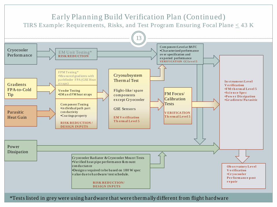
Early Planning Build Verification Plan (Continued) TIRS Example: Requirements, Risks, and Test Program Ensuring Focal Plane < 43 K
13
Cryocooler Performance
Component Level at BATC •Characterized performance ov er specification and ex pected performance VERIFICATION CC Level 5
Gradients FPA-to-Cold Tip
FPM Testing * •Mea sured gradients with pa thfinder FPA (GSE Heat straps)
V endor Testing •EM a n d FM heat straps
Component Testing •in dividual path part con ductivity •Coa tings property
Parasitic Heat Gain
EM Unit Testing*
*Tests listed in grey were using hardware that were thermally different from flight hardware
Cryosubsystem Thermal Test Flight-like/spare components except Cry ocooler GSE Sensors EM V erification T h ermal Level 5
Power Dissipation
Cryocooler Radiator & Cryocooler Mount Tests •Verified heat pipe performance & mount conductance •Designs required to be based on 1 80 W spec v alue due to hardware/test schedule.
RISK REDUCTION / DESIGN INPUTS
RISK REDUCTION/ DESIGN INPUTS
In strument Level V erification •FM t hermal Level 5 •Science Spec •Power Dissipation •Gradients/Parasitic
RISK REDUCTION
FM Focus/ Calibration Tests V ERIFICATION T h ermal Level 5
Observatory Level V erification •Cryocooler Performance post repair
Mid-Stage Planning 14
Review requirements, and engineering/science functions to develop performance tests.
Review requirements, thermal analysis, and higher level qualification plans prior to starting the component qualification program.
Identify components that are not in test (solar arrays, flight battery, etc.)
Review schedule and adjust test plan accordingly For example: originally the TIRS earth shield deployment test was planned to occur after the integration of the
optics/focal plane & cryocooler. However the hardware required for deployment (structure, strong back, earth shield) was available before the cryocooler delivery. The deployment test was shifted forward (prior to full integration) allowing TIRS to run focus/calibration testing concurrently thereby saving a month of schedule.
Identify any long term lead items needed for testing. (simulators, cryopanels, cryorefrigerators, control systems, etc).
For example: on WMAP the heater control racks available in our facility had “bang-bang” thermostatic controllers. Science required high thermal stability; therefore we needed to develop new heater control rack which interfaced with facility operator controls. This took approximately one year to develop/build.
For example: SAM required a specialized chamber simulated mars atmosphere be built, certified, and integrated with building facility this process took several years.

Performance/Science Test Influences
15
When developing the scripts for and the placement of performance/science testing
Environmental Ambient versus at Temperature (i.e. cryogenic, high temp)
Vacuum versus in Atmosphere Transition versus Plateau
Mission Influences Voltage Spacecraft Side

Detailed Planning 16
Establish a Regular Meeting Schedule Action Item List GSE and Flight Hardware Status Documentation Status Personnel Requirements
Develop the Thermal Profile Thermal Qualification (temperature levels, duration, survival) Turn-on/Removal of Power/Turn-off Engineering and Science Performance Tests
Plateaus versus Transitions A/B side Operation Voltage
Hardware Check-out Bake-out
Determine GSE set-up Emergency Planning
Risk Tolerance Flow Chart & Emergency Procedures
Create Documentation

Detailed Planning Typical Thermal Profile (Instrument/Observatory Level Test)
17
Performance Testing Aliveness, Short Form Functional, Long form Functional Pre and Post test at ambient for comparison At each plateau (SFF, LFF, or CPT); testing during transitions Day in the Life Test
Thermal Verification Hot Op, Cold Op, Survival Balances (specific voltage; flight environment simulation) Parametric Studies (Sensitivity) Hardware Checkout – heaters, thermostats, cryocooler, TECs, heat pipes, etc.
Thermal Qualification Four thermal cycles, survival soak, hot turn-on (2x), cold turn-on (2x), power down
Engineering Characterizations Mechanism Operation, Controller Tests, Deployments, Software, Jitter
Science/Calibration Tests Dependent on mission; done at plateaus and/or transitions
Contamination Bake-out; Contamination Certification
Note: specific testing is project dependent use as guideline only.

Detailed Planning Develop the Test Profile Example 1: ST5 Observatory TVAC
•4 cycles •Functional Test Baseline •CPT/Experiment •Voltage combos@ plateaus/transitions •Thermal balances •Bake-out •Survival Soak
Chamber break battery on line
Thermal Balances
Vacuum
18

Detailed Planning Develop the Test Profile Example 2: SAM Instrument Test 1
19
Simulating cruise check-out
Chamber break for loading organic solid samples
Heater & Laser Tuning

Detailed Planning Develop the Test Profile
Example 3: TIRS Instrument TVAC1 Pretest Profile (Voltage and A/B Side)
20
LFT – ambient operation functional TFT - cryogenic operation functional

Detailed Planning Testing during Transitions Example: CIRS Instrument Testing
21
Question: Why do you need to do performance testing during transitions? The extremes should “bound” the environmental conditions.
Answer: Although the plateaus bound the environment they may not be imposing the worst-case gradients; Testing during transitions uncovers workmanship issues.
Example: The first test of the Main Electronics Box on the CIRS instrument uncovered a workmanship issue with soldering of a component. The performance at the extreme temperatures was good; However a repeatable anomaly occurred at an intermediate temperature. The faulty solder joint was repaired and CIRS (Launch in 1997 on the Cassini Mission) has been collecting data on Saturn for the past 8 years… double its mission lifetime!

Detailed Planning Determining GSE Set-up 22
Types: MGSE (Scaffolding, Dollies, Slings, Accelerometers, etc.)
EGSE (Flight System, Simulators, Non-facility controllers, etc.)
CGSE (Scavenger plates, witness mirrors, QCMs, RGA, etc.)
TGSE/Facilities (Heater Control Racks, Test Sensors, TCUs, IR plates, Cryopanels, Cold plates, etc).
Science/Calibration Requirements: Simulates flight environment Drives temperature to qualification levels GSE and personnel can fit around chamber (Floor plan) Facility can support harnesses (Listing of connectors/feedthrus) Facility can support cold plates/cryopanels (listing of plumbing
feedthrus) GSE and flight hardware integration feasible (Storyboard)

Detailed Planning Determining GSE Set-up
Example: WMAP Observatory Level Test TGSE Set-up Thermal Design Environments
23
Cryogenic Instrument Isolated from S/C Bus
~ Room Temperature S/C Bus Shielded from Sun
Solar Arrays, Medium Gain Antenna and Bottom Deck Facing the Sun
Bottom Deck Silver Teflon Tape Pattern For Thruster Areas
PAF
MGA
L2 Orbit
Solar Arrays did not fit in chamber

Detailed Planning Determining GSE Set-up Example: WMAP Observatory Level Test TGSE Set-up Abbreviated
Storyboard
24
Central GSE Assembly
Bottom Deck LN2 Cryopanels
Heater Plates (six plates mounted to the bottom deck cryopanel)
GN2 controlled PAF cryopanel (made in two pieces and attached to the 30” stand)
Central GN2 Cryopanel
30” stand
Central GSE Assembly
Central GSE A ssembly
Bottom Deck LN2 Cryopanels (made in two halves)
Central GSE A ssembly
T hruster 4 /DSS Hea ter Plate
T hruster 2 Heater Plate
Medium Ga in A ntenna Heater Plate
T hruster 3 Heater Plate
T hruster 1 Heater Plate
Not e: Heater Plates are m ounted to the bottom deck cryopanels. There will be MLI closeouts (not shown) to the S/A stubs and bottom deck Solar
Array Stub Panels
Closeout MLI (between solar array stubs and main heater plates)
Web MLI (test article)

Detailed Planning Determining GSE Set-up Example: WMAP Observatory Level Test TGSE Set-up Abbreviated
Storyboard
25
X
Y
Z
Helium Cryopanels
Helium Cryopanel Support Structure
Bottom Deck GSE, Central GSE, & Solar Array Assemblies
Eight Calrods (for warm-up)
Helium Shroud
Bottom Deck GSE, Central GSE, & Solar Array Assemblies
The Instrument is inside the helium shroud. There is closeout MLI between the top deck and helium shroud.
Chamber at LN2

Detailed Planning Emergency Planning – Anything Can Happen!
26
Some Examples: JWST OSIM Test Loss of Facility Power (June 2012) TIRS Instrument Level Test Earthquake, Hurricane, and Fire (all within a couple of
weeks time period) SAM Test Solenoid Issue (Mars Gas Pressure) ST-5 Test Sudden Loss of Chamber Pressure WIRE Test Cryopanel Valve Failure CIRS Mirror Test LN2 Cryogen Leak CIRS Calibration Target Test Ice Plug UARS MMS Test Thermal Conditioning Unit Failure COBE DIRBE Test Loss of Facility Power
Several tests where GSE heater/power supply failed or severe snow storms/hurricanes resulted in using emergency procedures.

Detailed Planning Emergency Planning & Risk Tolerance
27
Establish contingency plan/procedures to ensure the test article’s safety in case of: Loss of Power (UPS; emergency generators) Loss of Vacuum Thermal GSE Failure (cryopanels, heaters, IR plate, TCU) Chamber Control Failure Flight Thermal Control System Failure Flight Article Failure/Loss of Commanding
Personnel safety and action Develop flow charts of actions Determine risk tolerance
Safety of Test Article Schedule Impacts
Implement redundancy based on risk tolerance
Flow Chart Example from
ST-5 plan

Detailed Planning Example: TIRS Instrument TVAC2 Thermal GSE Redundancy
28
Risk Tolerance was very low due to schedule. GSE Failures that needed a chamber break to repair would have resulted in large schedule delays (repairs plus cryogenic warm-up, additional bake-out, and cooldown). Hardware protection as well as providing environment for Science/Performance testing (TVAC levels) and Launch Lock Deployment were fully redundant.
Primary Redund. Redundancy
Type Notes
Cryocooler Radiator Base, Zone 1/Zone 2 1-1 2-1 P Additional protection for CC radiator +warm-up CC rad heat block (GSE on Flight Rad) 1-2 2-2 F Protects TMU / TVAC levels
CC Rad Cryo Panel 3-2 3-12 F Warm-up and LL deploy Earthshield stub Upper 1-4 N/A N* Thermal Balance Earthshield stub Lower 3-10 N/A N* Thermal Balance Hinge panels, Lower 1-5 2-12 F Protects Damper/ TVAC levels Hinge panels, Upper 2-8 3-9 F Protects Potentiometer / TVAC levels Telescope cryopanel 1-6 3-3 F Warm-up and LL deploy
FPE panel 1-9 2-9 F Protects FPE/ TVAC levels Structure enclosure + X 2-3 3-4 F
Protects Structure from LN2 Walls (required for calibration background) and TVAC Levels
Structure enclosure -Y 2-4 3-5 F Structure Enc. + Z Upper 2-5 3-6 F
Structure Encl. + Z Aperture 2-6 3-7 F Structure enclosure - Z 2-7 3-8 F
MEB Heater Plate MEB_HTR 2-10 F Protects MEB /TVAC levels CCE Heater Plate CCE_HTR 2-11 F Protects CCE/ TVAC levels
S/C Deck Simulator 1-7 1-8 F Protects Mounting flexures/Optical Deck Zero Q, SUDP Harness 1 1-10 N/A N Thermal Balance Zero Q, SUDP Harness 2 1-11 N/A N Thermal Balance Zero Q, MechDP Harness 1-12 N/A N Thermal Balance BB Calibrator Heater Plate BBCAL_PRI_HTR BBCAL_RED_HTR F Protects BB Cal + Science Performance
Payload Table 3-10 3-11 P Warm-up Only F- Full P- Partial N- None
*Hinge panels will keep hardware safe

Documentation 29
Test Plan Set-up, Test Profile Elements, Emergency Response, Personnel
Responsibilities, Success Criteria, Limits
Constraints Flight and Test
Procedures Set-up/Integration, Moving/Lifting, Pretest Checks, Thermal Balance,
Thermal Transitions, Functional/Science Testing
WOAs Step-by-Step Instructions/Procedure Identification
Good Documentation is Key to Successfully Conducting a TVAC test and Verifying Requirements!
Summary 30
Start Planning Early! Understand Requirements Develop Verification Matrix Design with Testing in Mind Review/Adjust Test Program Continuously Systems Team Should be Heavily Involved in Test Planning
to Ensure that Requirements will be Verified

Acronyms 31
AFT – Allowable Flight Temperature APG – Annealed Pyrolytic Graphite CCE – Cryocooler Control Electronics CCM- Cryocooler Mount CDR- Critical Design Review CGSE – Contamination Ground Support Equipment CIRS - Composite Infrared Spectrometer COBE – Cosmic Background Explorer CSS – Cryosubsystem EGSE –Electrical Ground Support Equipment EM- Engineering Model FM – Flight Model FPA – Focal Plane Assembly FPE – Focal Plane Electronics FPM – Functional Performance Model GEVS - General Environmental Verification Standard GSE – Ground Support Equipment GSFC - Goddard Space Flight Center ICD- Interface Control Document JWST – James Webb Space Telescope LN2 – Liquid Nitrogen MEB- Main Electronics Box MOU – Memorandum of Understanding MGSE – Mechanical Ground Support Equipment
NASA - National Aeronautics and Space Administration OSIM - Optical Telescope Element Simulator PER – Pre-Environmental Review PDR- Preliminary Design Review PSR – Pre-ship Review SAM – Sample Analysis at Mars SES – Space Environmental Simulator SIRTF - Space Infrared Telescope Facility SMEX - Small Explorers Program SHOOT- Super-fluid Helium On-Orbit Transfer ST5 – Space Technology 5 TEC – Thermal Electric Cooler TGSE – Thermal Ground Support Equipment TRACE - Transition Region and Coronal Explorer TIRS - Thermal Infrared Sensor TMU – Thermal Mechanical Unit TVAC (TV)- Thermal Vacuum TB – Thermal Balance TRR – Test Readiness Review UARS – Upper Atmosphere Research Satellite ULDB - Ultra-Long Duration Balloon WMAP - Wilkinson Microwave Anisotropy Probe WOA- Work Order Authorization XRS – X-Ray Spectrometer

Early Planning Build Verification Plan TIRS Example: Requirements, Risks, and Test Program
Back-up Slide Requirements 32
LEVEL 3 – INSTRUMENT ICD
TIRS-SC-280 The NTE internal power dissipations for the MEB and CCE shall be as shown in Table TIRS-SC-281. (MEB 65 W and CCE 49 W). LEVEL 4 – INSTRUMENT REQUIREMENTS (TIRS-SE-SPEC-0003 )
FS-496 At the nominal operating temperature of 43 K, the FPA shall have a combination of the minimum Conversion Efficiency (CE) and Dark Current (ID) such that the predicted (NEdT) for the 10.8 (10.5-11.5um) micron band and the 12.0 um band (11.3-12.3) with a 300 K target is less than 0.33 K.
FS-1012 The TIRS thermal control system shall meet the operating temperature and temperature stability as defined in table 3-8. The operational temperature of the non-science driven requirements are specified in TEVR. ( partial requirement shown here due to space considerations)
LEVEL 5 – CRYOCOOLER REQUIREMENTS (TIRS-SE-SPEC-0013 ) CC-201 The Cooler shall provide 2 W of cooling power at its Second-Stage Load interface at an operating set-point temperature under 38 K
given the Power Performance specified in Section 3.1.2 of this specification. CC-207 The Cooler shall meet the Cooling Performance specified in Section 3.1.1 of this Specification, at End Of Life (EOL) and a heat rejection
temperature of 273K, while drawing less than 225 W of spacecraft bus power. LEVEL 5 – THERMAL REQUIREMENTS (TIRS-SE-SPEC-007)
THRM-414 The thermal subsystem shall minimize the parasitic heat gains to ensure the cryocooler cold stage can meet cooling performance requirements as specified in CC-201 of cryocooler requirement document.
Sy stems sub-allocation of designing the cryocooler radiator to 180 Watts of dissipation in the TMU

Abstract 33
Thermal vacuum testing is the most complex and expensive of the environmental test campaign. The Instrument/Observatory Level Test is the ultimate verification of the Engineering/Science requirements over the flight environmental range. Early planning is essential to ensure that all mission, project, and NASA Goddard requirements are met. Detailed planning requires the coordination of subsystem, software, science, and facility personnel to have a successful test program and guarantee the safety of the hardware. This presentation will provide an overview of the systems planning process, potential effects on flight design/verification, basic thermal test elements and test profile development. Real life examples from Goddard missions are used to illustrate key points.

About the Presenter 34
Ms. Mosier is senior thermal systems engineer with the NASA Goddard Space Flight Center. Working primarily on in-house projects during her 29 years at NASA, Ms. Mosier has been instrumental in the planning and execution of over 25 instrument/observatory level thermal tests. Ms. Mosier is currently assigned as the thermal systems engineer on the TIRS instrument for the LDCM mission that is scheduled to launch in 2013. During her career at Goddard she has worked on many challenging projects including COBE, UARS, XRS, GRS, SHOOT, CIRS, WIRE, TRACE, SMEX-lite, SIRTF, JWST, ULDB, LISA, WMAP, XRS, ST-5, SAM, and TIRS. This has afforded a wide-range of testing experience from cryogenics to high-temperature systems in addition to the standard spacecraft testing. Ms. Mosier has been an instructor for spacecraft engineering design course at the University of Maryland. She also developed and teaches a thermal design course at NASA for civil servants and support contractors. Ms. Mosier is currently working with the NASA Engineering and Safety Center's (NESC) to develop standard training materials for thermal testing and thermal design/analysis.