Embed Size (px)
Citation preview

Stephen J. MellorProject Technology, Inc.http://www.projtech.com
Stephen J. MellorProject Technology, Inc.http://www.projtech.com
System Design:Architectures and
Archetypes
2
PROJECT TECHNOLOGY, INC.
System Design: Architectures and Archetypes
This tutorial shows you how to:v identify the characteristics that
determine the system design;v engineer the system-wide design
to meet performance constraints;v model the system-wide design—
the software architecture;v build archetypes to produce
efficient code.
3
PROJECT TECHNOLOGY, INC.
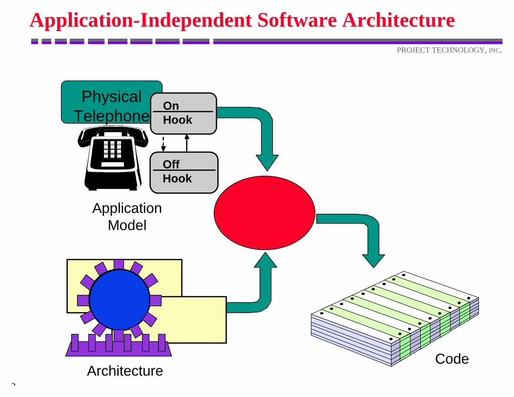
Application-Independent Software Architecture
PhysicalTelephone
OffHook
OnHook
ApplicationModel
ArchitectureCode
4
PROJECT TECHNOLOGY, INC.
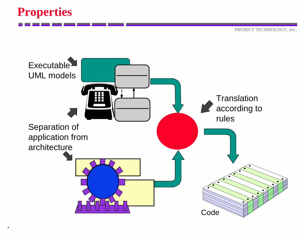
Properties
Separation ofapplication fromarchitecture
ExecutableUML models
Code
Translationaccording torules
5
PROJECT TECHNOLOGY, INC.
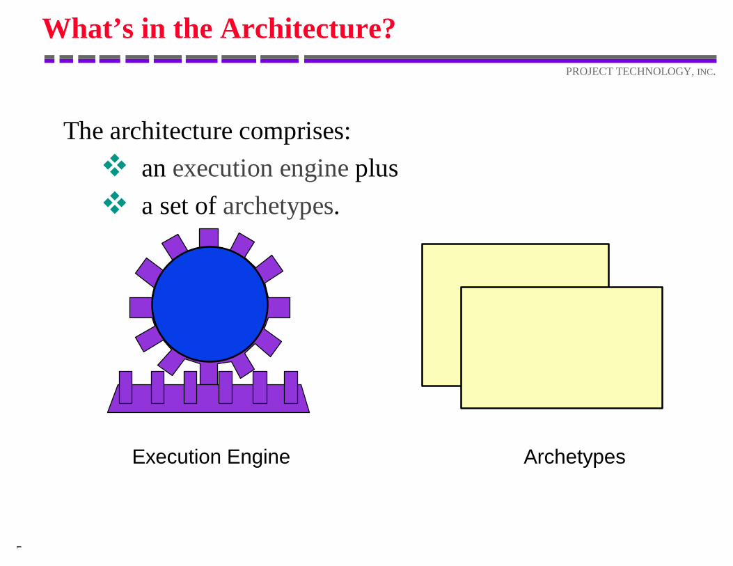
What’s in the Architecture?
The architecture comprises:v an execution engine plusv a set of archetypes.
Execution Engine Archetypes
6
PROJECT TECHNOLOGY, INC.
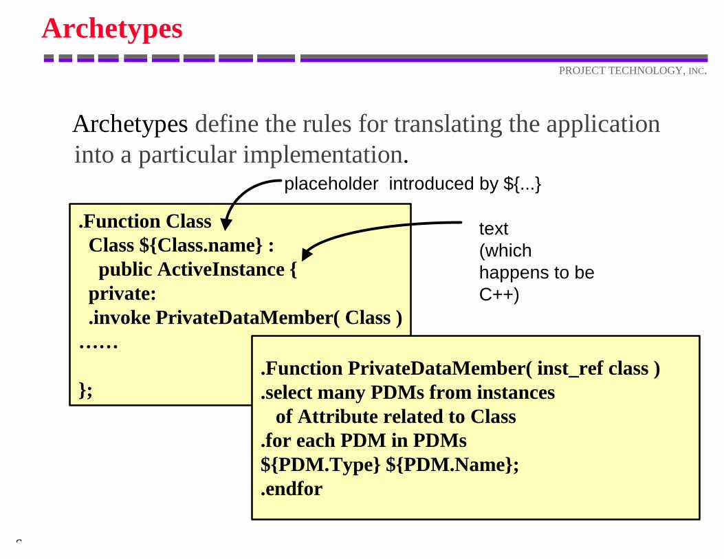
Archetypes
Archetypes define the rules for translating the applicationinto a particular implementation.
.Function Class Class ${Class.name} : public ActiveInstance { private: .invoke PrivateDataMember( Class )… …
};
placeholder introduced by ${...}
text(whichhappens to beC++)
.Function PrivateDataMember( inst_ref class )
.select many PDMs from instances of Attribute related to Class.for each PDM in PDMs${PDM.Type} ${PDM.Name};.endfor
7
PROJECT TECHNOLOGY, INC.
Application-Independent Software Architecture
The software architecture is independent of thesemantics of the application.
This offers:v early error detection through verificationv reuse of the architecturev faster performance tuningv faster integrationv faster, cheaper retargeting
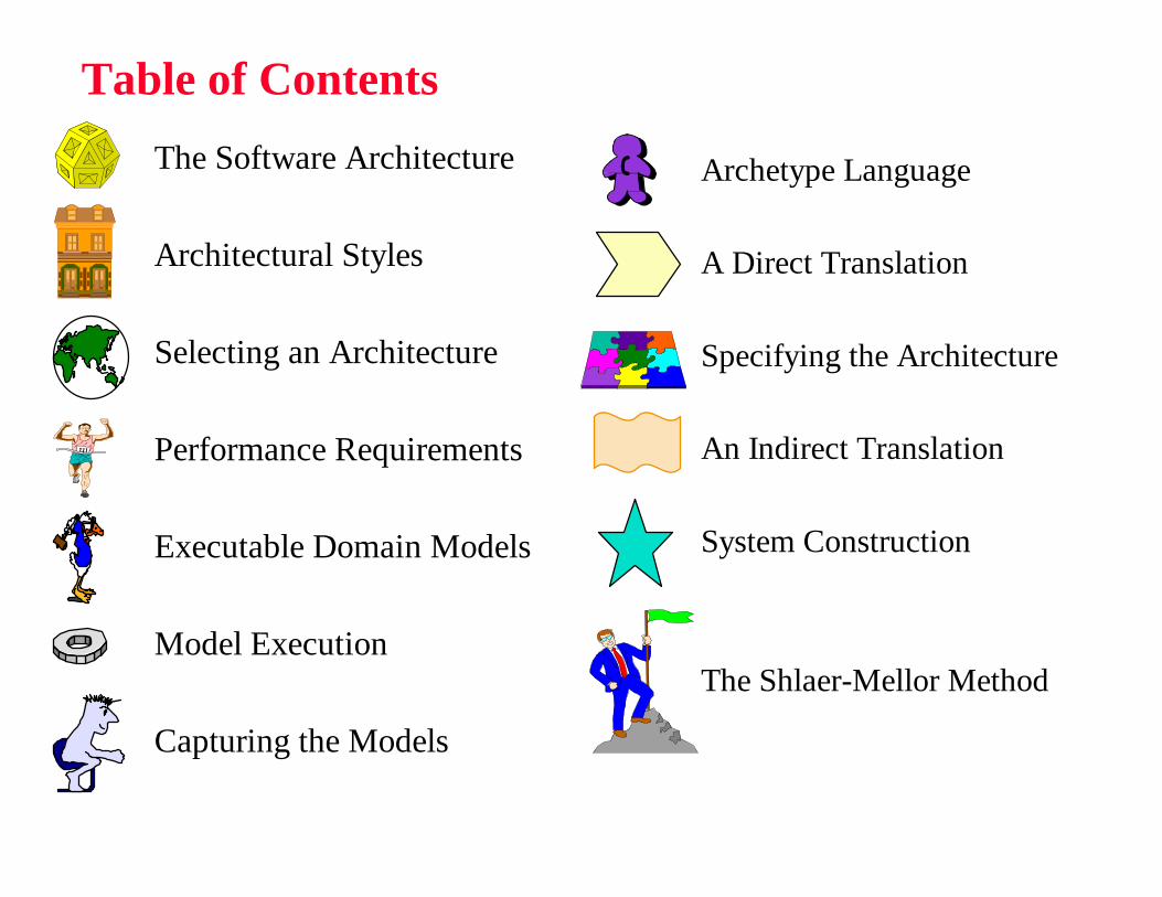
Table of Contents
The Software Architecture
Architectural Styles
Selecting an Architecture
Performance Requirements
Executable Domain Models
Model Execution
Capturing the Models
Archetype Language
A Direct Translation
Specifying the Architecture
An Indirect Translation
System Construction
The Shlaer-Mellor Method

The Software Architecture
10
PROJECT TECHNOLOGY, INC.
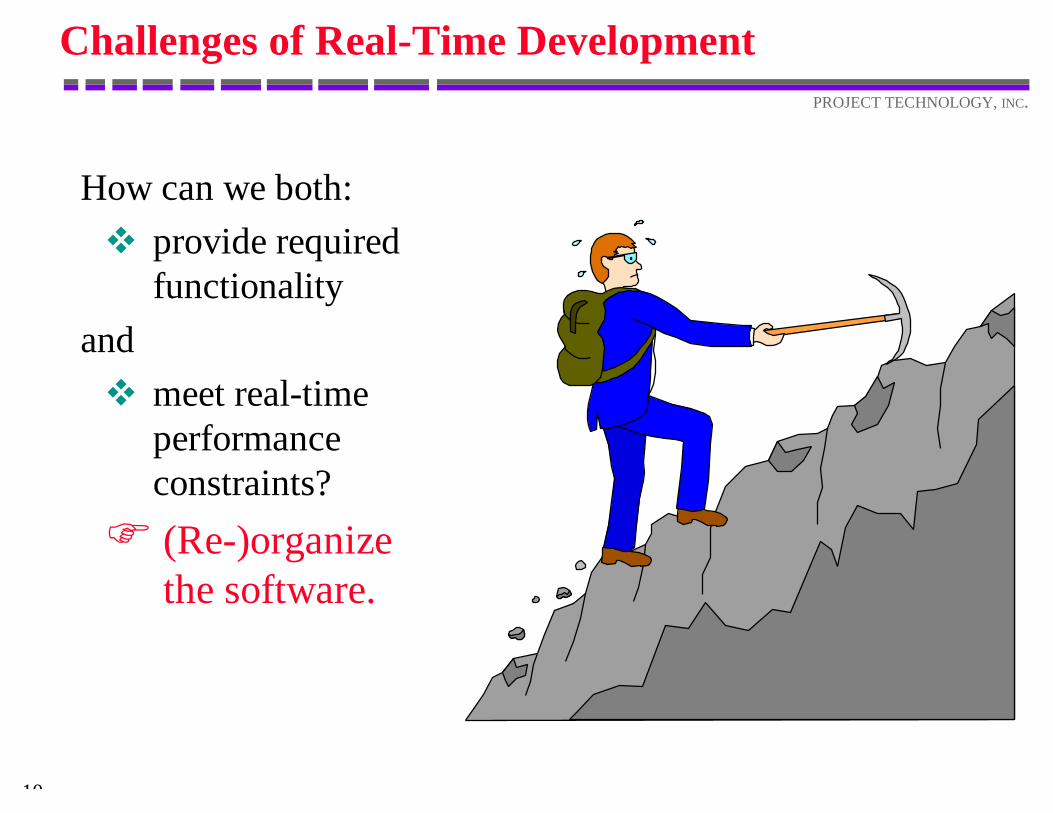
Challenges of Real-Time Development
How can we both:v provide required
functionalityandv meet real-time
performanceconstraints?F (Re-)organize
the software.
11
PROJECT TECHNOLOGY, INC.
Software Architecture
v datav controlv structuresv time
The abstract organization of software is called thesoftware architecture.
It proclaims and enforces system-wide rules forthe organization of:
12
PROJECT TECHNOLOGY, INC.
Data
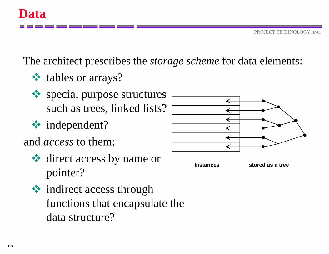
v tables or arrays?v special purpose structures
such as trees, linked lists?v independent?
and access to them:v direct access by name or
pointer?v indirect access through
functions that encapsulate thedata structure?
The architect prescribes the storage scheme for data elements:
Instances stored as a tree
13
PROJECT TECHNOLOGY, INC.
Control
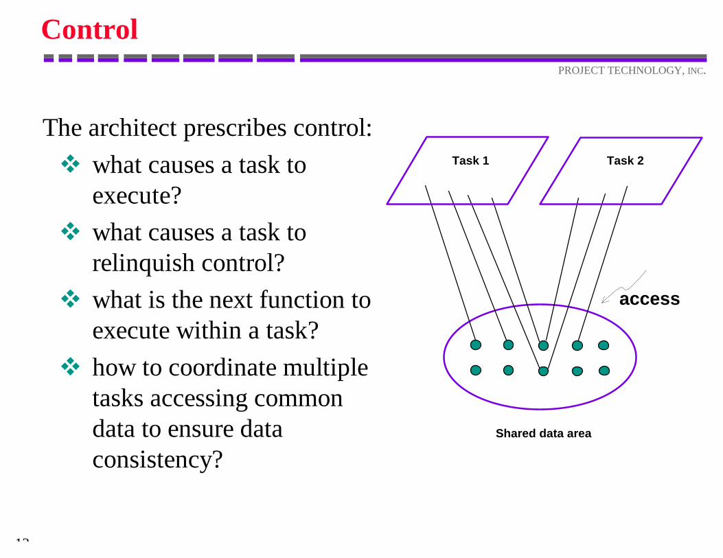
The architect prescribes control:v what causes a task to
execute?v what causes a task to
relinquish control?v what is the next function to
execute within a task?v how to coordinate multiple
tasks accessing commondata to ensure dataconsistency?
Task 1 Task 2
access
Shared data area
14
PROJECT TECHNOLOGY, INC.
Structures
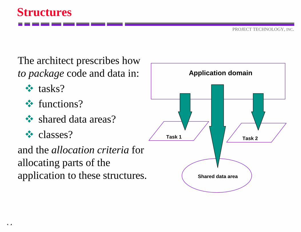
The architect prescribes howto package code and data in:v tasks?v functions?v shared data areas?v classes?
and the allocation criteria forallocating parts of theapplication to these structures.
Application domain
Task 1 Task 2
Shared data area
15
PROJECT TECHNOLOGY, INC.
Time
v absolute timev relative time
The software architect prescribes howto provide time-related services:
16
PROJECT TECHNOLOGY, INC.
Uniformity
v reduces cost ofunderstanding, building,and maintaining thesoftware
v decreases integration effortv leads to smaller, more
robust code
A minimal, uniform set of organization rules:

Architectural Styles
18
PROJECT TECHNOLOGY, INC.
Architectural Styles
v Monitor and controlv Transportersv Transactions
Real-time and embedded systemscommonly employ (parts of) threemajor architectural styles:
19
PROJECT TECHNOLOGY, INC.
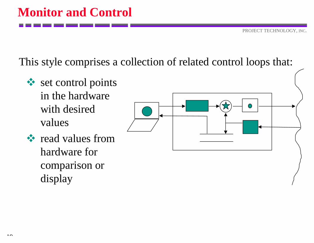
Monitor and Control
v set control pointsin the hardwarewith desiredvalues
v read values fromhardware forcomparison ordisplay
This style comprises a collection of related control loops that:
20
PROJECT TECHNOLOGY, INC.
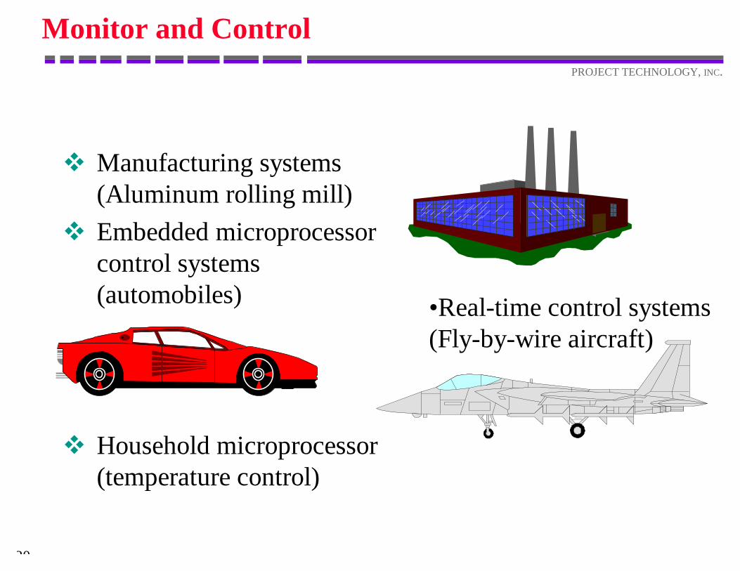
Monitor and Control
v Manufacturing systems(Aluminum rolling mill)
v Embedded microprocessorcontrol systems(automobiles)
v Household microprocessor(temperature control)
•Real-time control systems (Fly-by-wire aircraft)
21
PROJECT TECHNOLOGY, INC.
Monitor and Control
This style tends to have:v hard response deadlinesv data that must have
current valuesv significant computation
on the data
22
PROJECT TECHNOLOGY, INC.
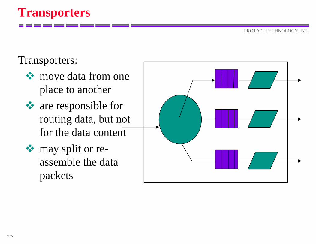
Transporters
Transporters:v move data from one
place to anotherv are responsible for
routing data, but notfor the data content
v may split or re-assemble the datapackets
23
PROJECT TECHNOLOGY, INC.
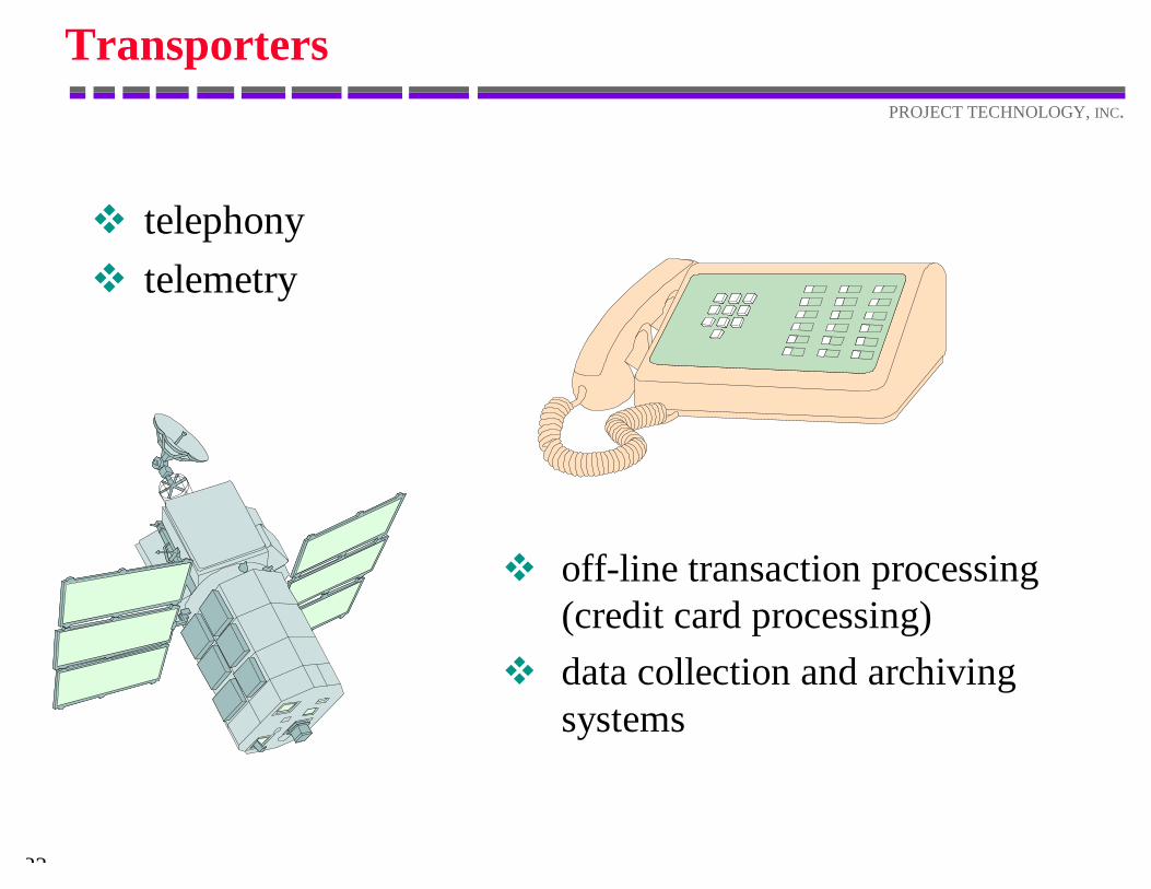
Transporters
v telephonyv telemetry
v off-line transaction processing(credit card processing)
v data collection and archivingsystems
24
PROJECT TECHNOLOGY, INC.
Transporters
Transporters:v must meet throughput
requirementsv may have response time
requirements on somestreams
v have persistent applicationdata describing routing
v must manage bufferscontaining applicationpackets
25
PROJECT TECHNOLOGY, INC.
Transactions
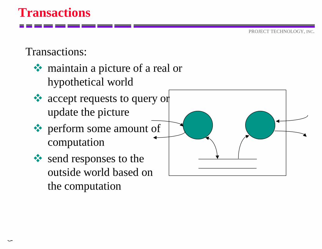
Transactions:v maintain a picture of a real or
hypothetical worldv accept requests to query or
update the picturev perform some amount of
computationv send responses to the
outside world based onthe computation
26
PROJECT TECHNOLOGY, INC.
Transactions
v on-line bankingv reservation systemsv simulatorsv desktop applications
(word processors,spreadsheets)
27
PROJECT TECHNOLOGY, INC.
Transactions
This style tends to have:v considerable persistent
application datav variable response timesv significant throughput
requirements
28
PROJECT TECHNOLOGY, INC.
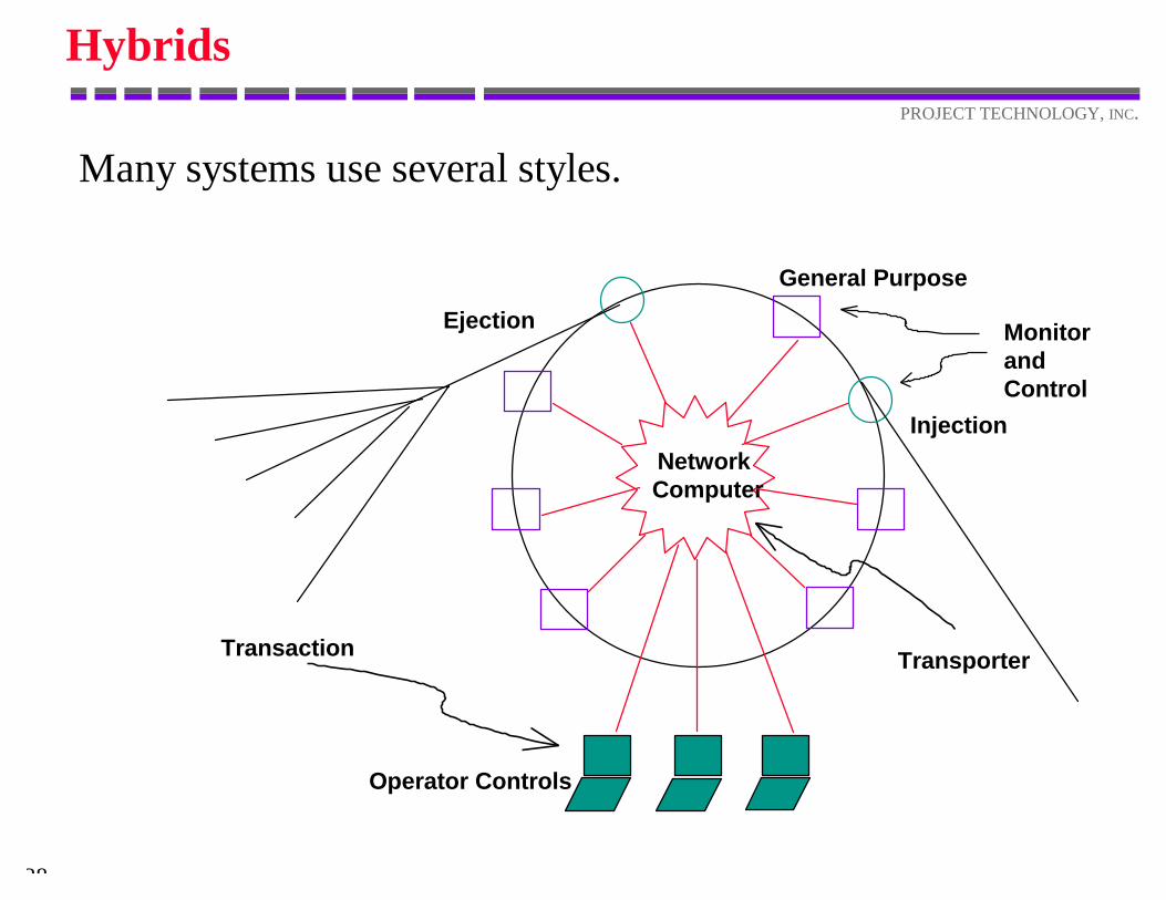
Hybrids
Many systems use several styles.
General Purpose
Ejection
Injection
Operator Controls
NetworkComputer
Transaction
MonitorandControl
Transporter

Selecting an Architecture
30
PROJECT TECHNOLOGY, INC.
Characterize the System
“[E]very design problem begins with an effort toachieve a fitness between two entities: the form inquestion and its context. The form is the solutionto the problem; the context defines the problem.In other words, when we speak of design, the realobject of discussion is not the form alone, but theensemble comprising the form and its context.Good fit is a desired property of this ensemblewhich relates to some particular division of theensemble into form and context.”
Notes on the Synthesis of FormChristopher Alexander
31
PROJECT TECHNOLOGY, INC.
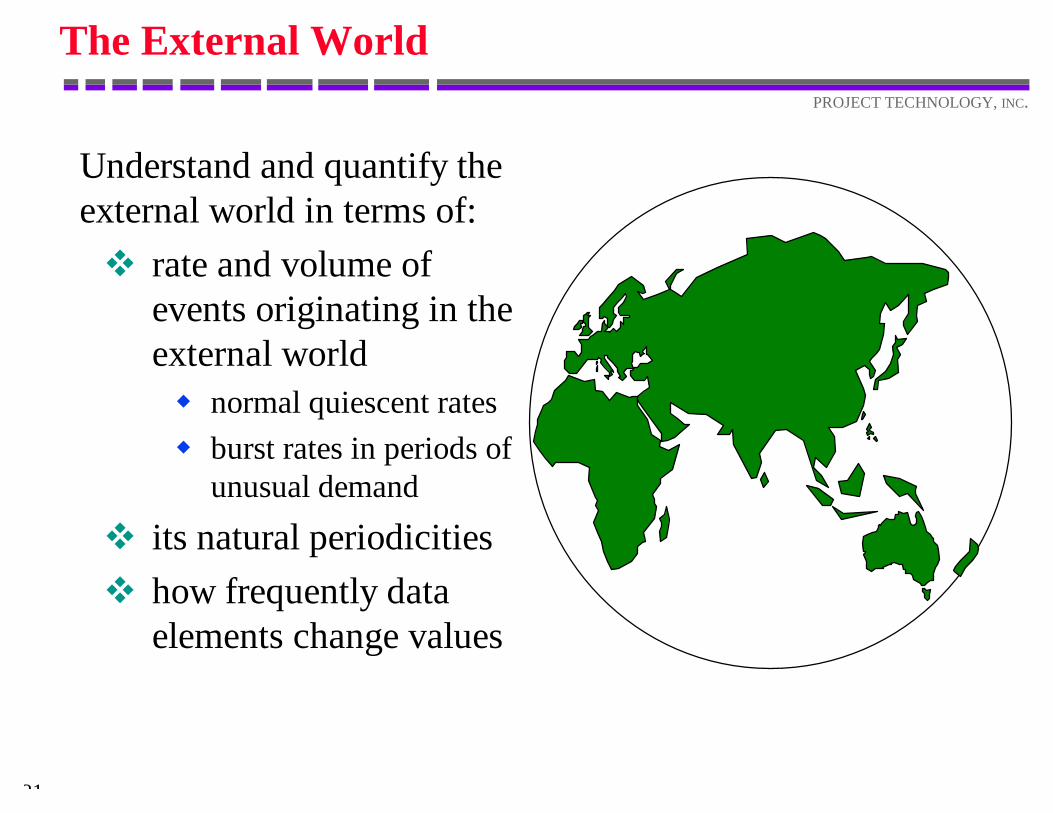
The External World
Understand and quantify theexternal world in terms of:v rate and volume of
events originating in theexternal worldw normal quiescent ratesw burst rates in periods of
unusual demand
v its natural periodicitiesv how frequently data
elements change values
32
PROJECT TECHNOLOGY, INC.
Non-Localized Requirements
Requirements Meetingv continuous 24 x 7 operationv fault tolerance and recoveryv personnel and equipment safety
33
PROJECT TECHNOLOGY, INC.
Business Constraints
Understand andenumerate anyconstraints thebusiness may placeon the architecture.
• number / location of processors• upward compatability• choice of hardware platforms• choice of software platforms
34
PROJECT TECHNOLOGY, INC.
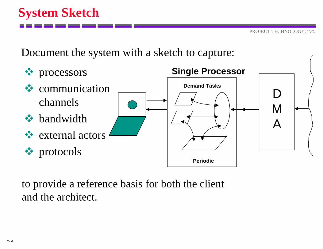
System Sketch
v processorsv communication
channelsv bandwidthv external actorsv protocols
Document the system with a sketch to capture:
to provide a reference basis for both the clientand the architect.
DMA
Single ProcessorDemand Tasks
Periodic
Performance Requirements
36
PROJECT TECHNOLOGY, INC.
The High Spots
“It is common practice in engineering, if we wishto make a metal face perfectly smooth, to fit itagainst the surface of a metal block which islevel within finer limits than we are aiming at, byinking the surface of this standard block andrubbing our metal face against the inked surface.If our metal face is not quite level, ink marksappear on it at those points that are higher thanthe rest. We grind away at these high spots...”
Notes on the Synthesis of FormChristopher Alexander
37
PROJECT TECHNOLOGY, INC.
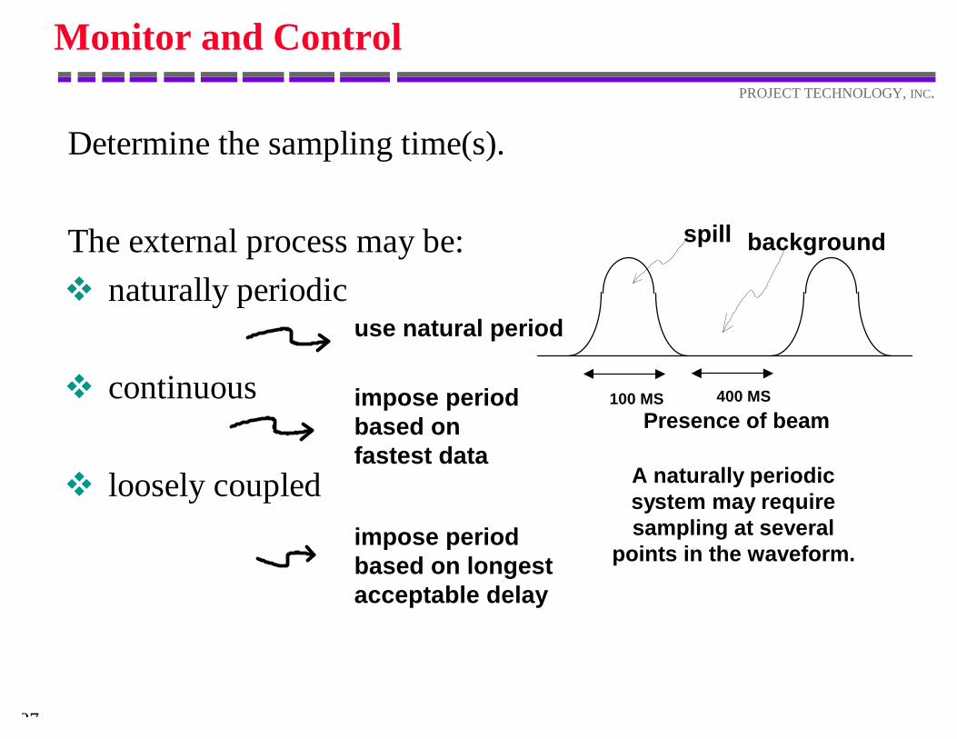
Monitor and Control
Determine the sampling time(s).
The external process may be:v naturally periodic
v continuous
v loosely coupled
impose period based on fastest data
use natural period
impose period based on longest acceptable delay
100 MS 400 MS
spill background
Presence of beam
A naturally periodicsystem may requiresampling at several
points in the waveform.
38
PROJECT TECHNOLOGY, INC.
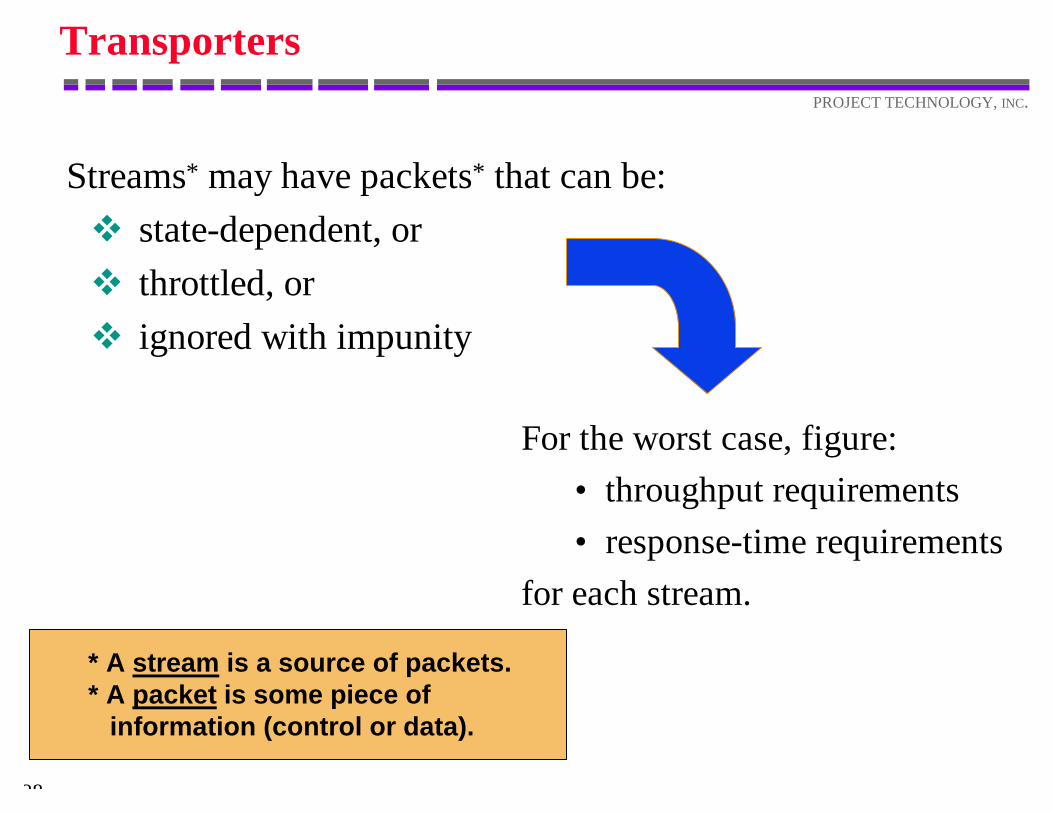
Transporters
Streams* may have packets* that can be:v state-dependent, orv throttled, orv ignored with impunity
For the worst case, figure:• throughput requirements• response-time requirements
for each stream.
* A stream is a source of packets.* A packet is some piece of information (control or data).
39
PROJECT TECHNOLOGY, INC.
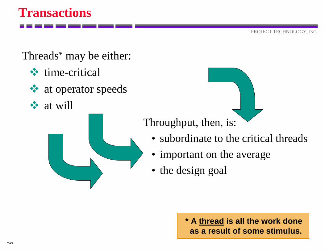
Transactions
Threads* may be either:v time-criticalv at operator speedsv at will
Throughput, then, is:• subordinate to the critical threads• important on the average• the design goal
* A thread is all the work done as a result of some stimulus.
40
PROJECT TECHNOLOGY, INC.
Performance Quantification
To quantify performance requirements in an analysis:v Identify critical threadsv Identify worst burstsv Identify the required processing for each
Only do this for the“high spots!”
Executable DomainModels
42
PROJECT TECHNOLOGY, INC.
Unified Modeling Language
“The Unified Modeling Language is a language forspecifying, constructing, visualizing, anddocumenting the artifacts of a software-intensivesystem.”
The UML Summary
43
PROJECT TECHNOLOGY, INC.
© 1998 Model Integration, LLC
UML Models
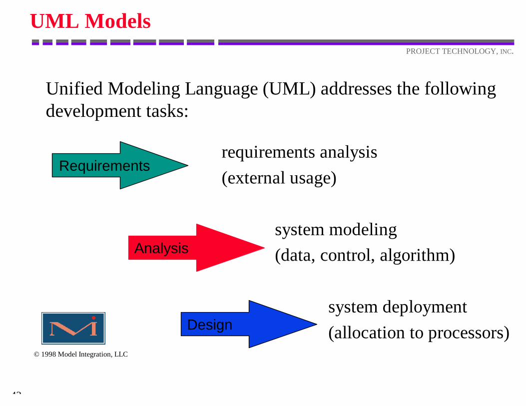
Unified Modeling Language (UML) addresses the followingdevelopment tasks:
Requirements
Analysis
Design
requirements analysis (external usage)
system modeling (data, control, algorithm)
system deployment (allocation to processors)
44
PROJECT TECHNOLOGY, INC.
© 1998 Model Integration, LLC
UML Model Notation
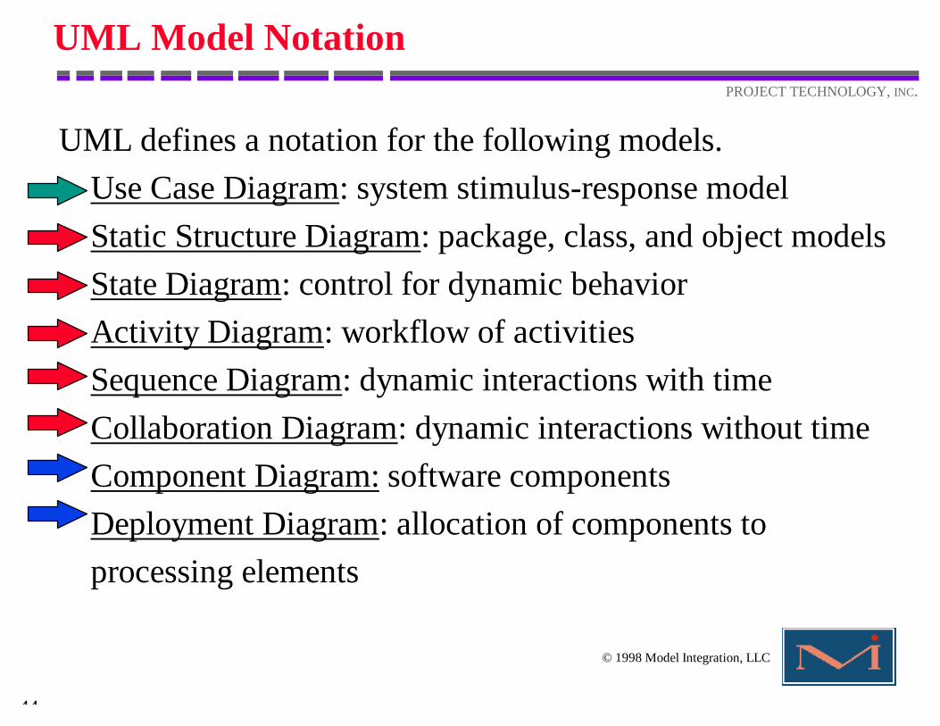
UML defines a notation for the following models.Use Case Diagram: system stimulus-response modelStatic Structure Diagram: package, class, and object modelsState Diagram: control for dynamic behaviorActivity Diagram: workflow of activitiesSequence Diagram: dynamic interactions with timeCollaboration Diagram: dynamic interactions without timeComponent Diagram: software componentsDeployment Diagram: allocation of components toprocessing elements
45
PROJECT TECHNOLOGY, INC.
© 1998 Model Integration, LLC
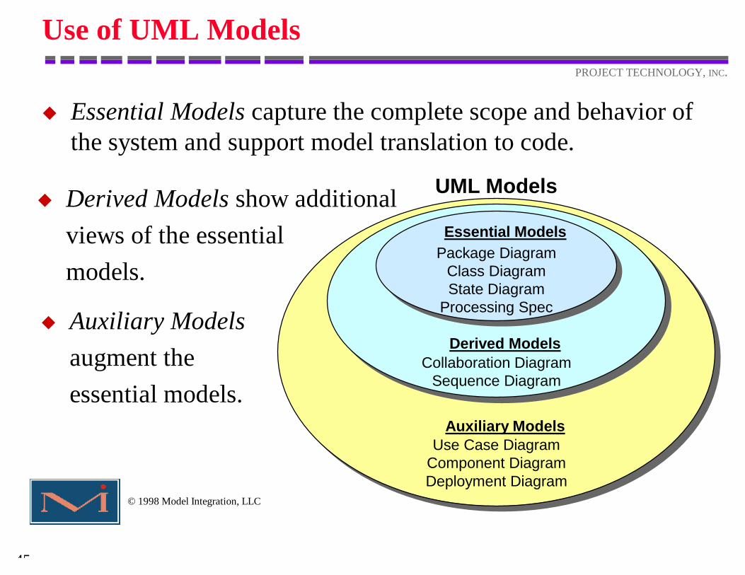
Use of UML Models
u Essential Models capture the complete scope and behavior ofthe system and support model translation to code.
u Auxiliary Modelsaugment theessential models.
u Derived Models show additionalviews of the essentialmodels.
Package DiagramClass DiagramState Diagram
Processing Spec
Essential Models
Collaboration DiagramSequence Diagram
Derived Models
Use Case DiagramComponent DiagramDeployment Diagram
Auxiliary Models
UML Models
46
PROJECT TECHNOLOGY, INC.
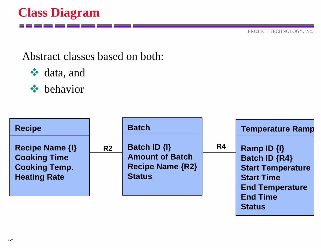
Class Diagram
Abstract classes based on both:v data, andv behavior
Recipe
Recipe Name {I}Cooking TimeCooking Temp.Heating Rate
R2
Batch
Batch ID {I}Amount of BatchRecipe Name {R2}Status
Temperature Ramp
Ramp ID {I}Batch ID {R4}Start TemperatureStart TimeEnd TemperatureEnd TimeStatus
R4
47
PROJECT TECHNOLOGY, INC.
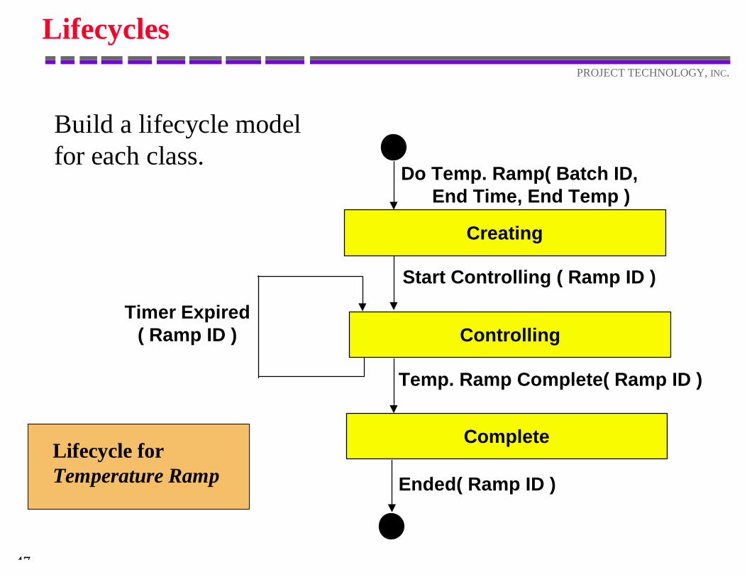
Lifecycles
Build a lifecycle modelfor each class.
Lifecycle for Temperature Ramp
Do Temp. Ramp( Batch ID, End Time, End Temp )
Creating
Controlling
Complete
Start Controlling ( Ramp ID )
Temp. Ramp Complete( Ramp ID )
Ended( Ramp ID )
Timer Expired( Ramp ID )
48
PROJECT TECHNOLOGY, INC.
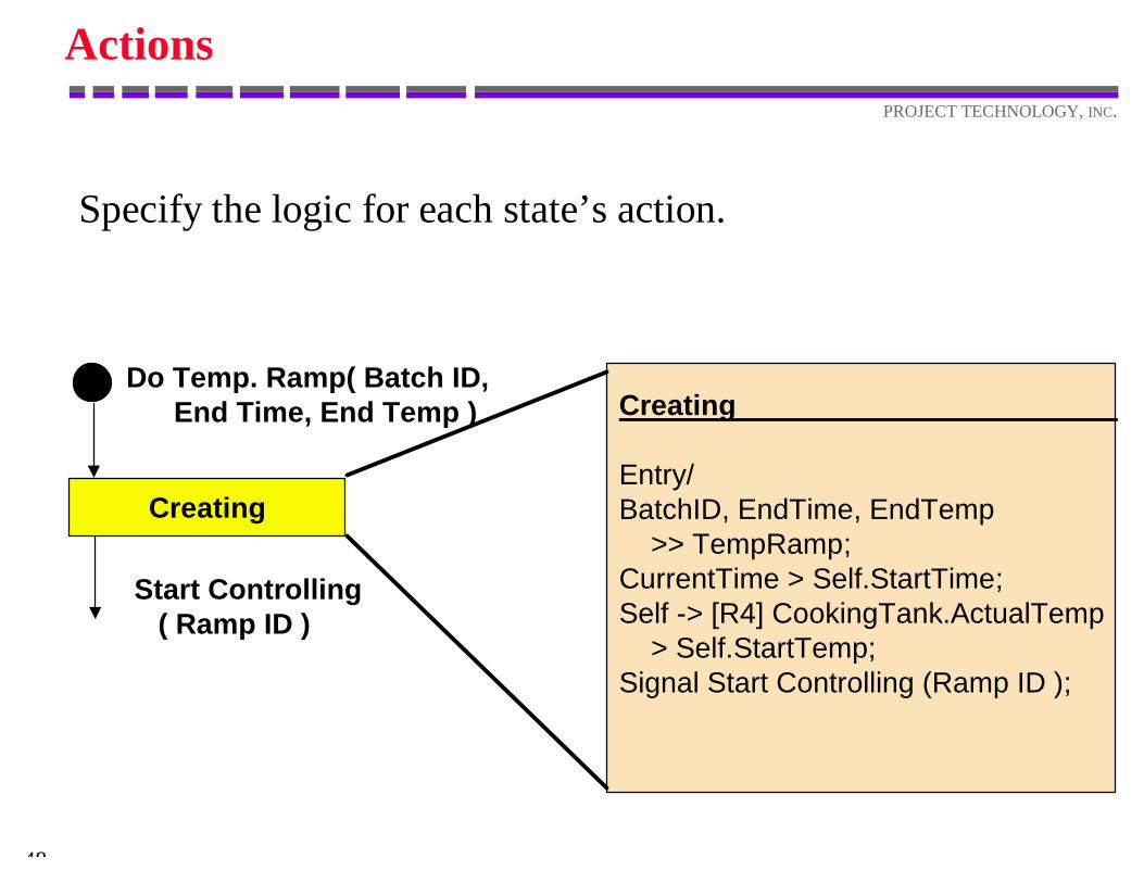
Actions
Specify the logic for each state’s action.
Do Temp. Ramp( Batch ID, End Time, End Temp )
Creating
Start Controlling ( Ramp ID )
Creating
Entry/BatchID, EndTime, EndTemp >> TempRamp;CurrentTime > Self.StartTime;Self -> [R4] CookingTank.ActualTemp > Self.StartTemp;Signal Start Controlling (Ramp ID );
49
PROJECT TECHNOLOGY, INC.
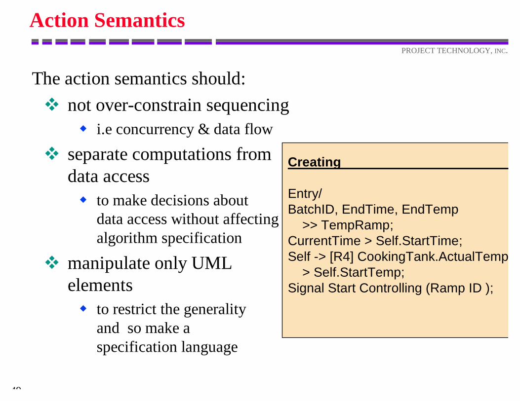
Action Semantics
The action semantics should:v not over-constrain sequencing
w i.e concurrency & data flow
v separate computations fromdata accessw to make decisions about
data access without affectingalgorithm specification
v manipulate only UMLelementsw to restrict the generality
and so make aspecification language
Creating
Entry/BatchID, EndTime, EndTemp >> TempRamp;CurrentTime > Self.StartTime;Self -> [R4] CookingTank.ActualTemp > Self.StartTemp;Signal Start Controlling (Ramp ID );
50
PROJECT TECHNOLOGY, INC.
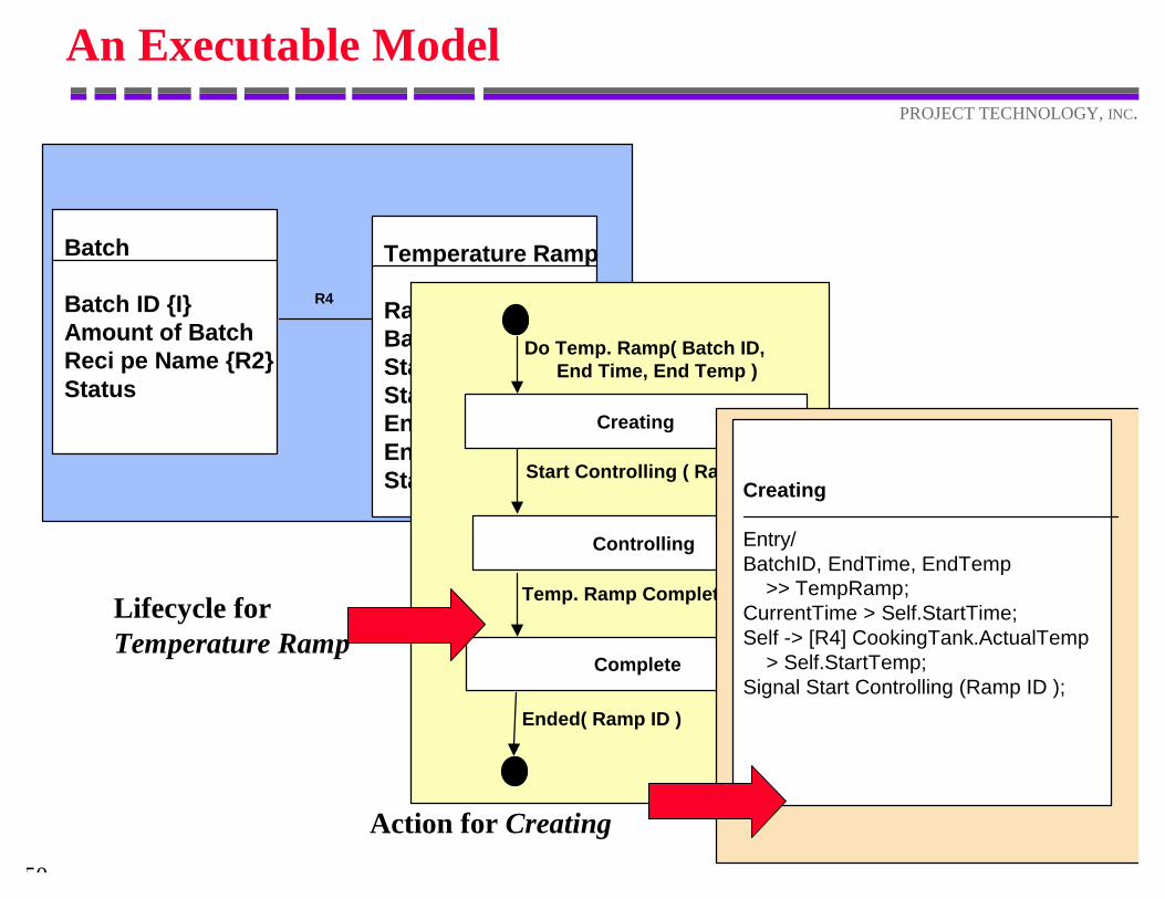
An Executable Model
Batch
Batch ID {I}Amount of BatchReci pe Name {R2}Status
Temperature Ramp
Ramp ID {I}Batch ID {R4}Start TemperatureStart TimeEnd TemperatureEnd TimeStatus
R4
Lifecycle for Temperature Ramp
Action for Creating
Do Temp. Ramp( Batch ID, End Time, End Temp )
Creating
Controlling
Complete
Start Controlling ( Ramp ID )
Temp. Ramp Complete( Ramp ID )
Ended( Ramp ID )
Creating
Entry/BatchID, EndTime, EndTemp >> TempRamp;CurrentTime > Self.StartTime;Self -> [R4] CookingTank.ActualTemp > Self.StartTemp;Signal Start Controlling (Ramp ID );
ModelExecution
52
PROJECT TECHNOLOGY, INC.
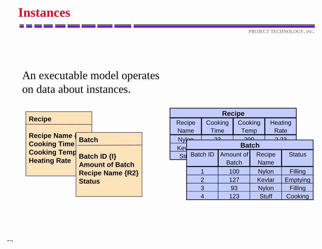
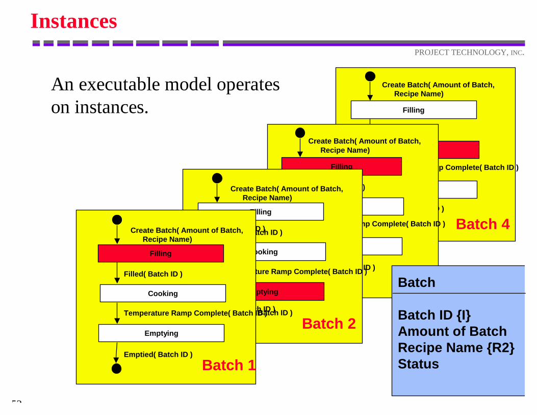
Instances
RecipeRecipe Name
Cooking Time
Cooking Temp
Heating Rate
Nylon 23 200 2.23Kevlar 45 250 4.69Stuff 67 280 1.82
BatchBatch ID Amount of
BatchRecipe Name
Status
1 100 Nylon Filling2 127 Kevlar Emptying3 93 Nylon Filling4 123 Stuff Cooking
Recipe
Recipe Name {I}Cooking TimeCooking TemperatureHeating Rate
Batch
Batch ID {I}Amount of BatchRecipe Name {R2}Status
An executable model operateson data about instances.
53
PROJECT TECHNOLOGY, INC.
Filling
Cooking
Emptying
Create Batch( Amount of Batch, Recipe Name)
Filled( Batch ID )
Temperature Ramp Complete( Batch ID )
Emptied( Batch ID )
Batch 4
Instances
An executable model operateson instances.
Filling
Cooking
Emptying
Create Batch( Amount of Batch, Recipe Name)
Temperature Ramp Complete( Batch ID )
Filled( Batch ID )
Emptied( Batch ID )
Filling
Cooking
Emptying
Create Batch( Amount of Batch, Recipe Name)
Filled( Batch ID )
Temperature Ramp Complete( Batch ID )
Emptied( Batch ID )
Batch 2
Batch
Batch ID {I}Amount of BatchRecipe Name {R2}Status
Filled( Batch ID )
Emptied( Batch ID )
Filling
Cooking
Emptying
Create Batch( Amount of Batch, Recipe Name)
Filled( Batch ID )
Temperature Ramp Complete( Batch ID )
Emptied( Batch ID )
Batch 1
54
PROJECT TECHNOLOGY, INC.
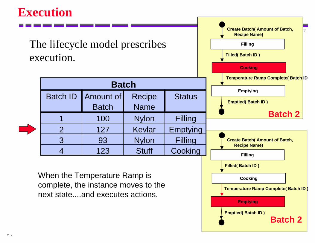
Execution
The lifecycle model prescribesexecution.
Filling
Cooking
Emptying
Create Batch( Amount of Batch, Recipe Name)
Filled( Batch ID )
Emptied( Batch ID )
Batch 2
Filled( Batch ID )
Filling
Cooking
Emptying
Create Batch( Amount of Batch, Recipe Name)
Filled( Batch ID )
Temperature Ramp Complete( Batch ID )
Emptied( Batch ID )
Batch 2
BatchBatch ID Amount of
BatchRecipe Name
Status
1 100 Nylon Filling2 127 Kevlar Emptying3 93 Nylon Filling4 123 Stuff Cooking
Temperature Ramp Complete( Batch ID )
When the Temperature Ramp iscomplete, the instance moves to thenext state....and executes actions.
55
PROJECT TECHNOLOGY, INC.
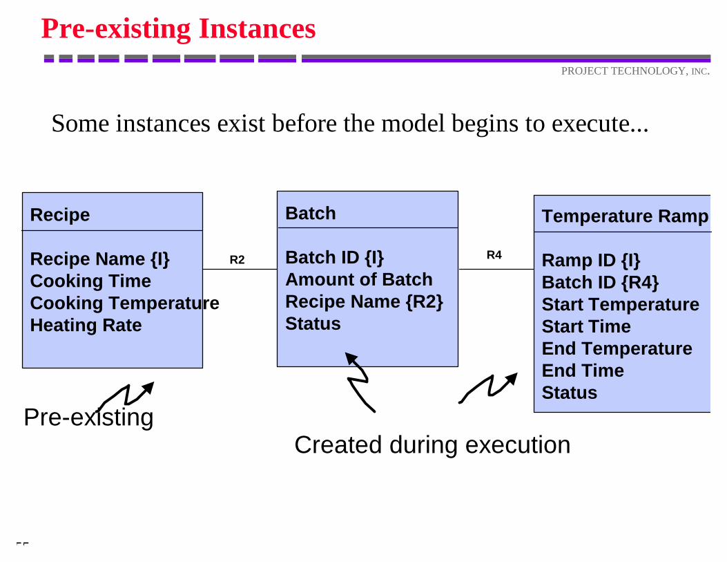
Pre-existing Instances
Some instances exist before the model begins to execute...
Recipe
Recipe Name {I}Cooking TimeCooking TemperatureHeating Rate
R2
Batch
Batch ID {I}Amount of BatchRecipe Name {R2}Status
Temperature Ramp
Ramp ID {I}Batch ID {R4}Start TemperatureStart TimeEnd TemperatureEnd TimeStatus
R4
Created during executionPre-existing
56
PROJECT TECHNOLOGY, INC.
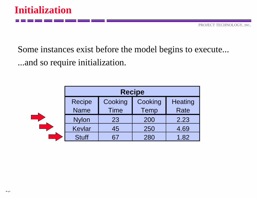
Initialization
RecipeRecipe Name
Cooking Time
Cooking Temp
Heating Rate
Nylon 23 200 2.23Kevlar 45 250 4.69Stuff 67 280 1.82
Some instances exist before the model begins to execute......and so require initialization.
57
PROJECT TECHNOLOGY, INC.
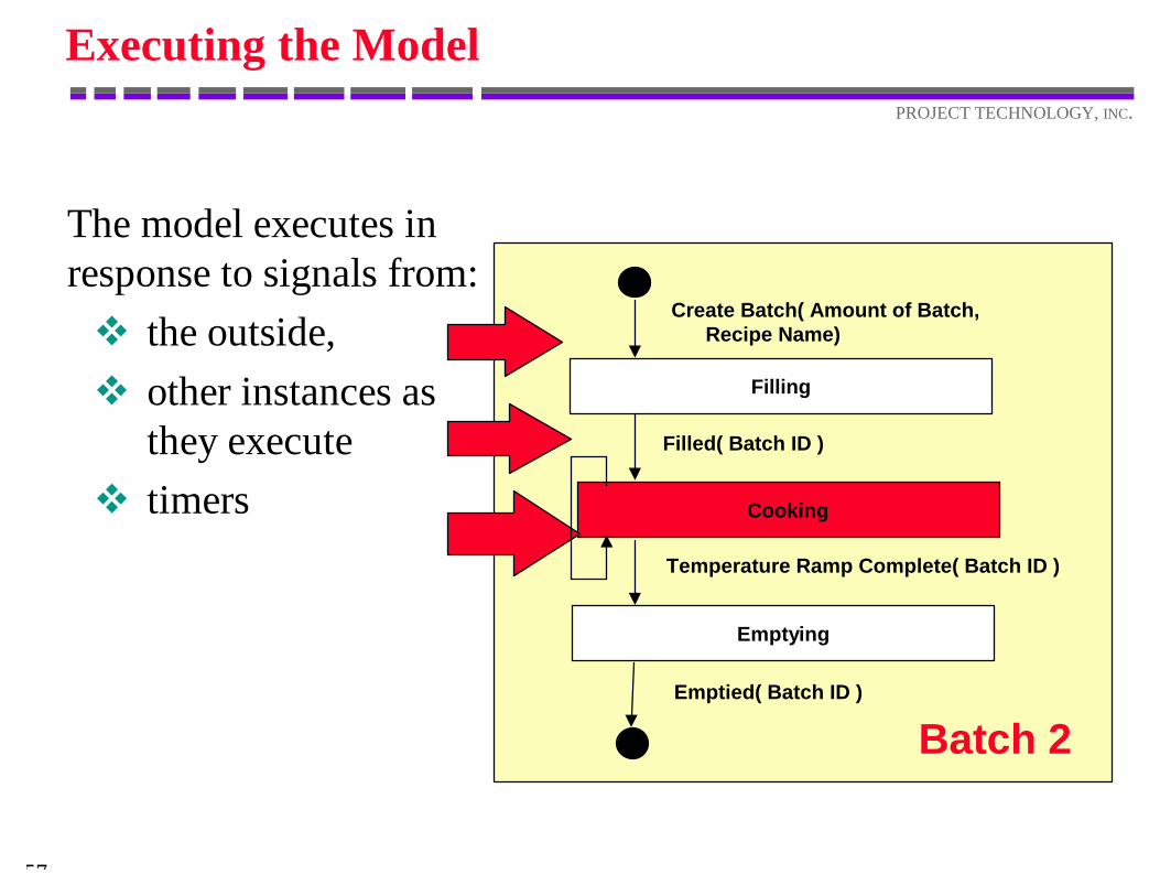
Executing the Model
The model executes inresponse to signals from:v the outside,v other instances as
they executev timers
Filling
Cooking
Emptying
Create Batch( Amount of Batch, Recipe Name)
Filled( Batch ID )
Emptied( Batch ID )
Batch 2
Temperature Ramp Complete( Batch ID )
58
PROJECT TECHNOLOGY, INC.
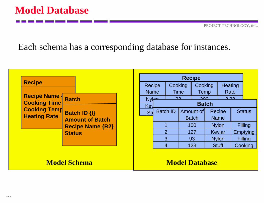
Model Database
Each schema has a corresponding database for instances.
RecipeRecipe Name
Cooking Time
Cooking Temp
Heating Rate
Nylon 23 200 2.23Kevlar 45 250 4.69Stuff 67 280 1.82
BatchBatch ID Amount of
BatchRecipe Name
Status
1 100 Nylon Filling2 127 Kevlar Emptying3 93 Nylon Filling4 123 Stuff Cooking
Recipe
Recipe Name {I}Cooking TimeCooking TemperatureHeating Rate
Batch
Batch ID {I}Amount of BatchRecipe Name {R2}Status
Model Schema Model Database
Capturing The Models
60
PROJECT TECHNOLOGY, INC.
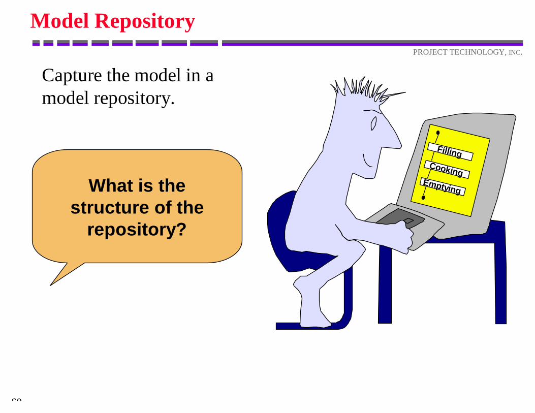
Model Repository
Capture the model in amodel repository.
FillingCooking
EmptyingWhat is thestructure of the
repository?
61
PROJECT TECHNOLOGY, INC.
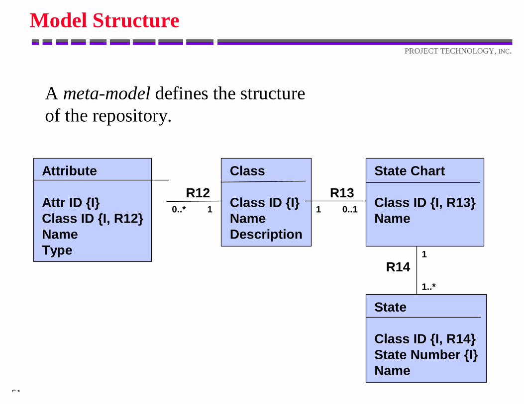
Model Structure
A meta-model defines the structureof the repository.
Attribute
Attr ID {I}Class ID {I, R12}NameType
R120..* 1
State Chart
Class ID {I, R13}Name
Class
Class ID {I}NameDescription
R131 0..1
State
Class ID {I, R14}State Number {I}Name
1
1..*
R14
62
PROJECT TECHNOLOGY, INC.
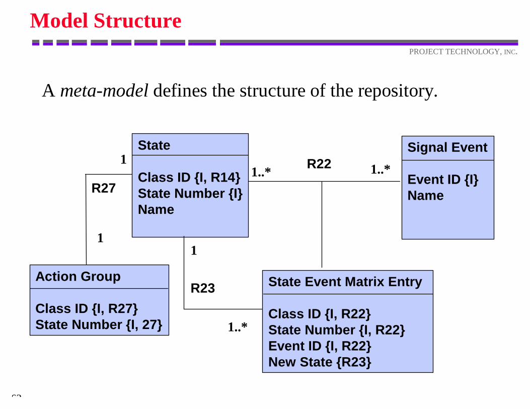
Model Structure
A meta-model defines the structure of the repository.
State Event Matrix Entry
Class ID {I, R22}State Number {I, R22}Event ID {I, R22}New State {R23}
State
Class ID {I, R14}State Number {I}Name
Signal Event
Event ID {I}Name
R22
R23
1..* 1..*
1
1..*
Action Group
Class ID {I, R27}State Number {I, 27}
1
1
R27
63
PROJECT TECHNOLOGY, INC.
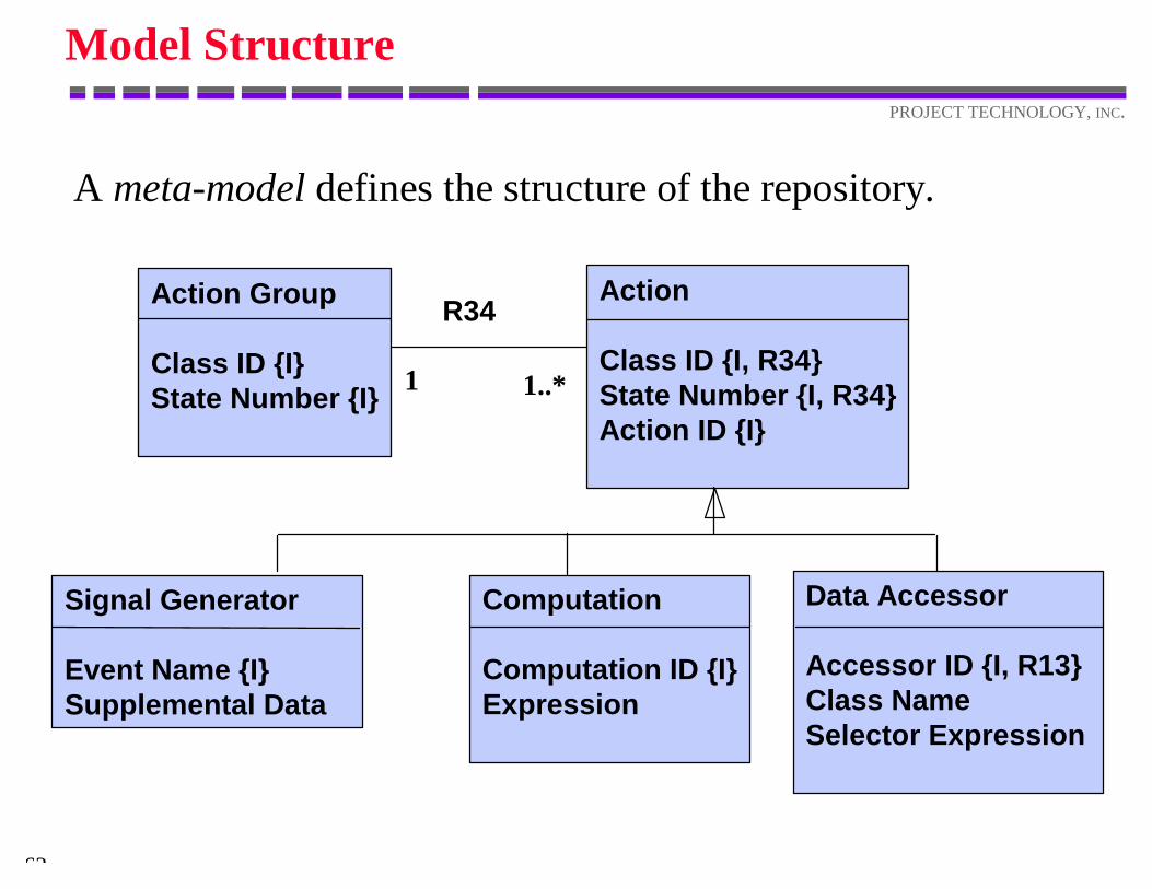
Model Structure
A meta-model defines the structure of the repository.
Signal Generator
Event Name {I}Supplemental Data
Data Accessor
Accessor ID {I, R13}Class NameSelector Expression
Action
Class ID {I, R34}State Number {I, R34}Action ID {I}
R34Action Group
Class ID {I}State Number {I}
Computation
Computation ID {I}Expression
1 1..*
64
PROJECT TECHNOLOGY, INC.
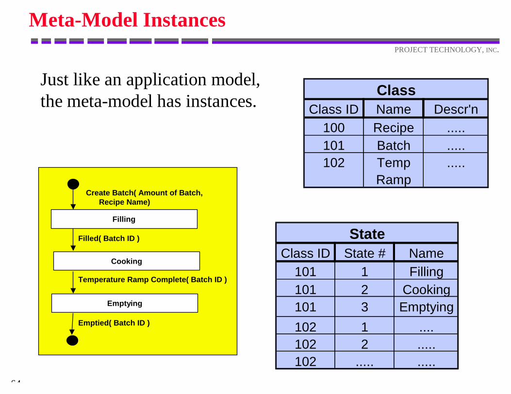
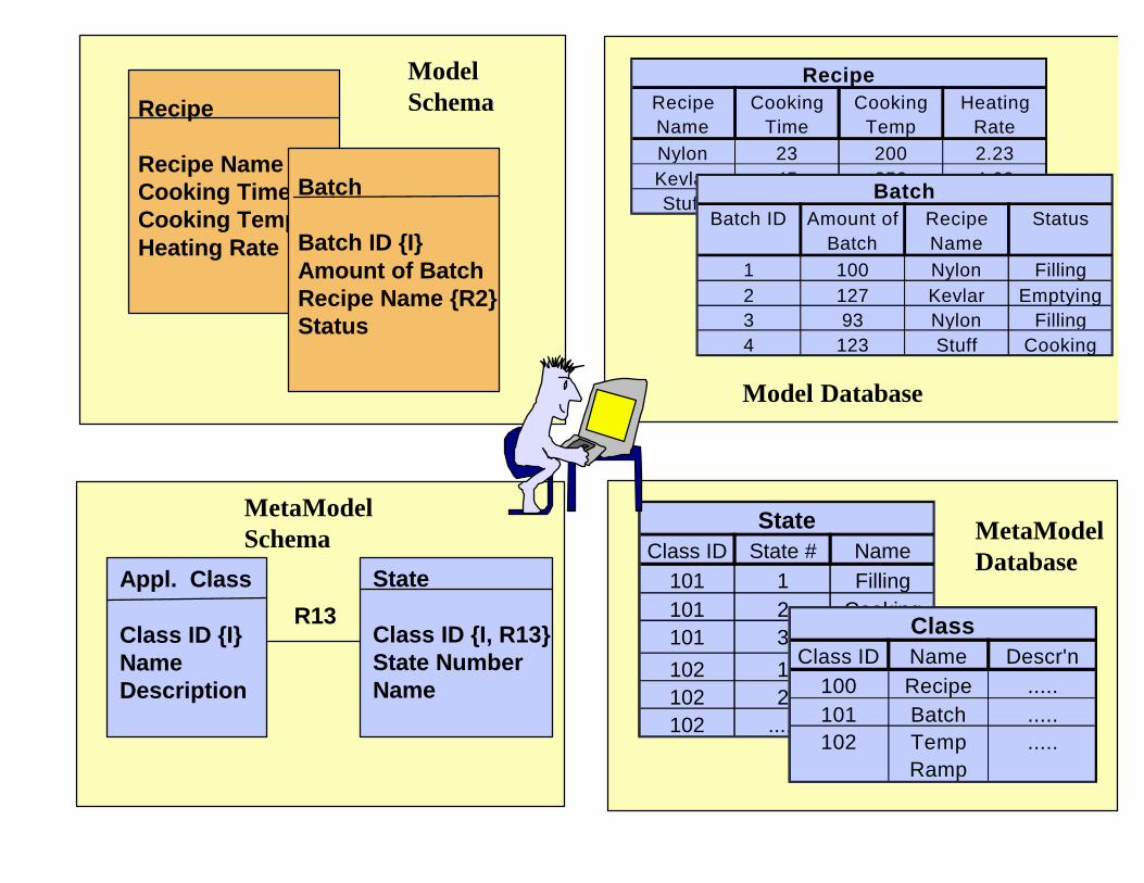
Meta-Model Instances
Just like an application model,the meta-model has instances.
ClassClass ID Name Descr'n
100 Recipe .....101 Batch .....102 Temp
Ramp.....
StateClass ID State # Name
101 1 Filling101 2 Cooking101 3 Emptying102 1 ....102 2 .....102 ..... .....
Filling
Cooking
Emptying
Create Batch( Amount of Batch, Recipe Name)
Filled( Batch ID )
Temperature Ramp Complete( Batch ID )
Emptied( Batch ID )
Recipe
Recipe Name {I}Cooking TimeCooking TemperatureHeating Rate
Batch
Batch ID {I}Amount of BatchRecipe Name {R2}Status
ModelSchema
RecipeRecipe Name
Cooking Time
Cooking Temp
Heating Rate
Nylon 23 200 2.23Kevlar 45 250 4.69Stuff 67 280 1.82Batch
Batch ID Amount of Batch
Recipe Name
Status
1 100 Nylon Filling2 127 Kevlar Emptying3 93 Nylon Filling4 123 Stuff Cooking
Model Database
StateClass ID State # Name
101 1 Filling101 2 Cooking101 3 Emptying102 1 ....102 2 .....102 ..... .....
ClassClass ID Name Descr'n
100 Recipe .....101 Batch .....102 Temp
Ramp.....
MetaModelDatabase
State
Class ID {I, R13}State NumberName
Appl. Class
Class ID {I}NameDescription
R13
MetaModelSchema
PROJECT TECHNOLOGY
Shlaer–Mellor Method n BridgePoint
INC.
ArchetypeLanguage
68
PROJECT TECHNOLOGY, INC.
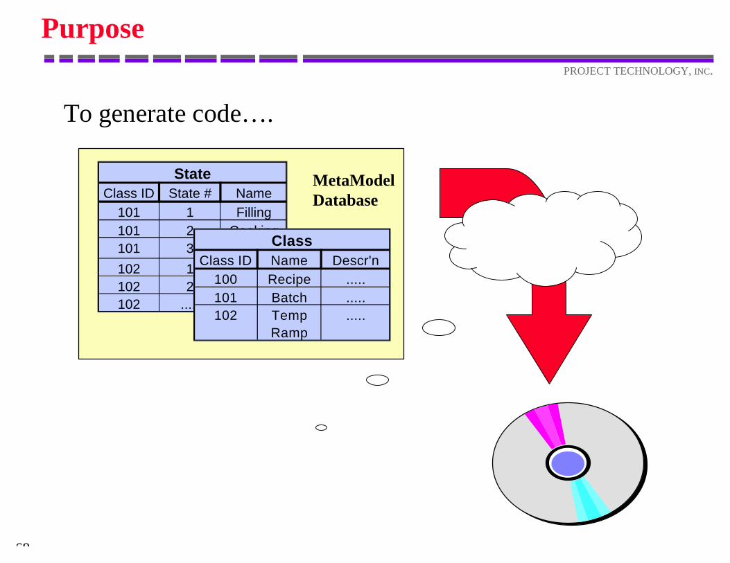
Purpose
To generate code… .
StateClass ID State # Name
101 1 Filling101 2 Cooking101 3 Emptying102 1 ....102 2 .....102 ..... .....
ClassClass ID Name Descr'n
100 Recipe .....101 Batch .....102 Temp
Ramp.....
MetaModelDatabase
69
PROJECT TECHNOLOGY, INC.
Purpose
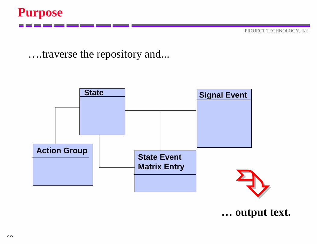
… .traverse the repository and...
Action Group State EventMatrix Entry
State Signal Event
… output text.ÊÊ
70
PROJECT TECHNOLOGY, INC.
Example
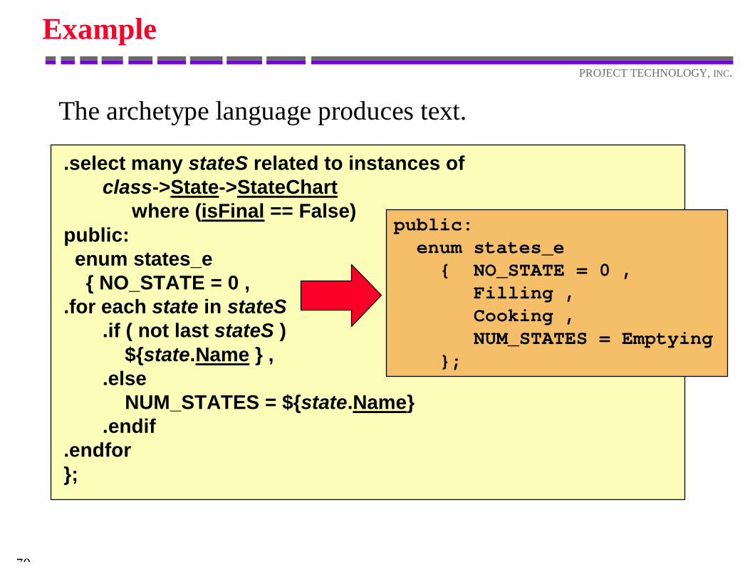
The archetype language produces text.
.select many stateS related to instances of class->State->StateChart
where (isFinal == False)public: enum states_e { NO_STATE = 0 ,.for each state in stateS .if ( not last stateS ) ${state.Name } , .else NUM_STATES = ${state.Name} .endif.endfor};
public: enum states_e { NO_STATE = 0 , Filling , Cooking , NUM_STATES = Emptying };
71
PROJECT TECHNOLOGY, INC.
Text
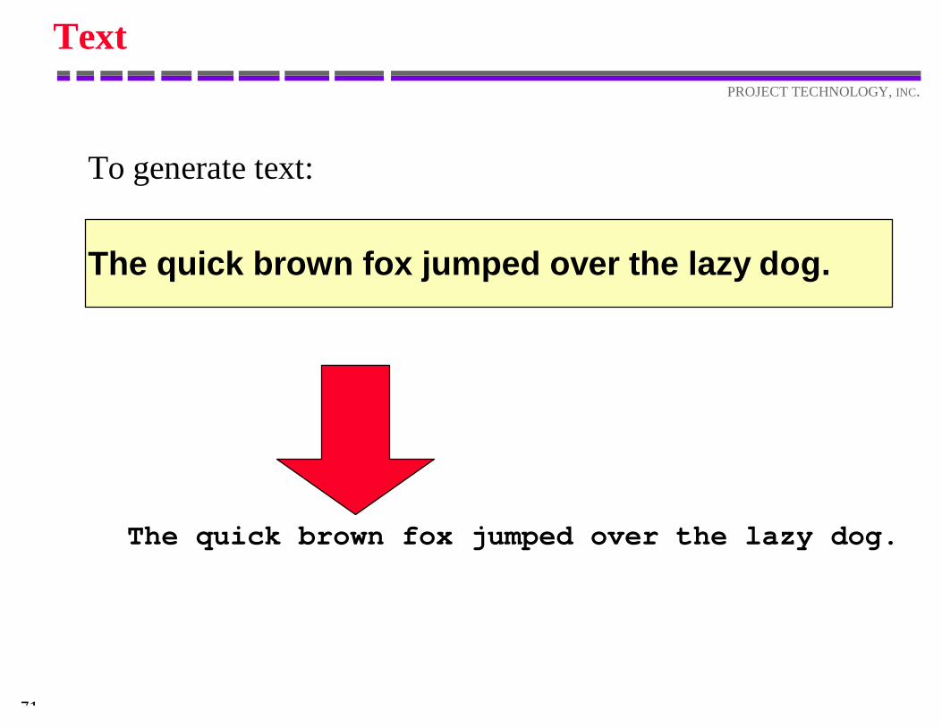
To generate text:
The quick brown fox jumped over the lazy dog.
The quick brown fox jumped over the lazy dog.
72
PROJECT TECHNOLOGY, INC.
Data Access
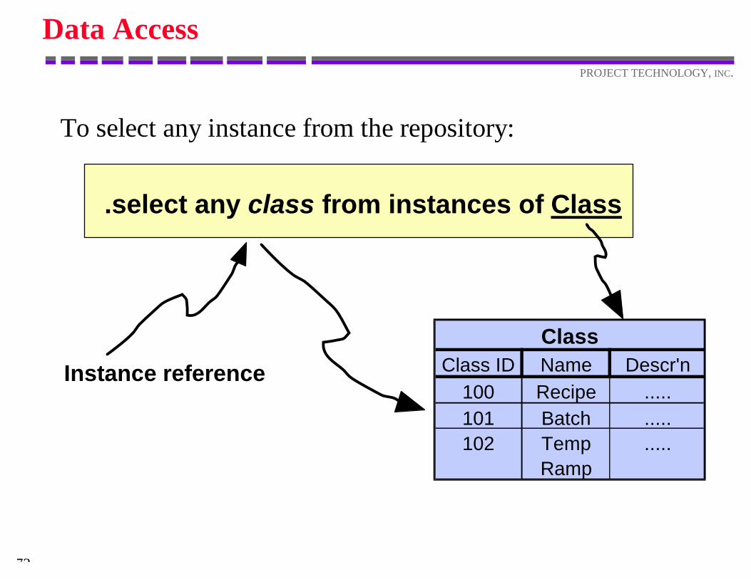
To select any instance from the repository:
.select any class from instances of Class
Instance reference
ClassClass ID Name Descr'n
100 Recipe .....101 Batch .....102 Temp
Ramp.....
73
PROJECT TECHNOLOGY, INC.
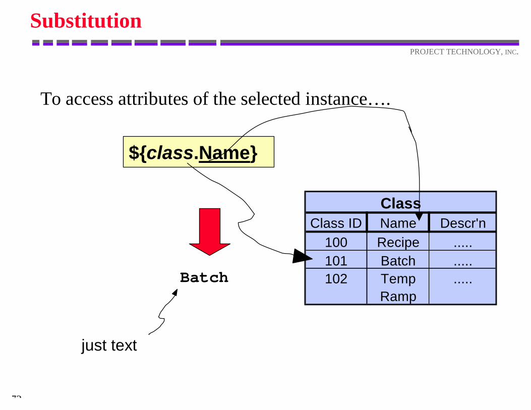
Substitution
To access attributes of the selected instance… .
${class.Name}
ClassClass ID Name Descr'n
100 Recipe .....101 Batch .....102 Temp
Ramp.....Batch
just text
74
PROJECT TECHNOLOGY, INC.
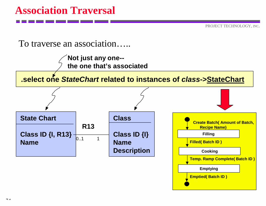
Association Traversal
To traverse an association… ..
.select one StateChart related to instances of class->StateChart
State Chart
Class ID {I, R13}Name
Class
Class ID {I}NameDescription
R13
0..1 1Filling
Cooking
Emptying
Create Batch( Amount of Batch, Recipe Name)
Filled( Batch ID )
Temp. Ramp Complete( Batch ID )
Emptied( Batch ID )
Not just any one--the one that’s associated
75
PROJECT TECHNOLOGY, INC.
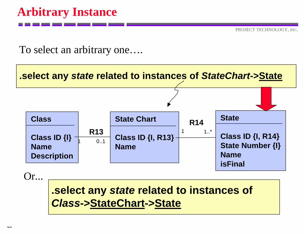
Arbitrary Instance
To select an arbitrary one… .
.select any state related to instances of StateChart->State
State Chart
Class ID {I, R13}Name
Class
Class ID {I}NameDescription
R131 0..1
1 1..*R14 State
Class ID {I, R14}State Number {I}NameisFinal
.select any state related to instances ofClass->StateChart->State
Or...
76
PROJECT TECHNOLOGY, INC.
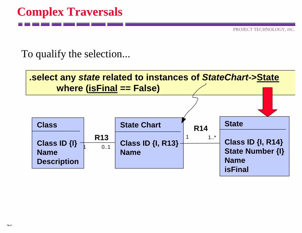
Complex Traversals
To qualify the selection...
State Chart
Class ID {I, R13}Name
Class
Class ID {I}NameDescription
R131 0..1
1 1..*R14 State
Class ID {I, R14}State Number {I}NameisFinal
.select any state related to instances of StateChart->Statewhere (isFinal == False)
77
PROJECT TECHNOLOGY, INC.
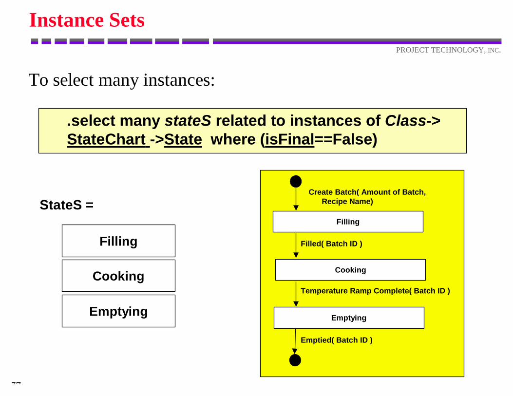
Instance Sets
To select many instances:
.select many stateS related to instances of Class->StateChart ->State where (isFinal==False)
Filling
Cooking
Emptying
Create Batch( Amount of Batch, Recipe Name)
Filled( Batch ID )
Temperature Ramp Complete( Batch ID )
Emptied( Batch ID )
StateS =
Filling
Cooking
Emptying
78
PROJECT TECHNOLOGY, INC.
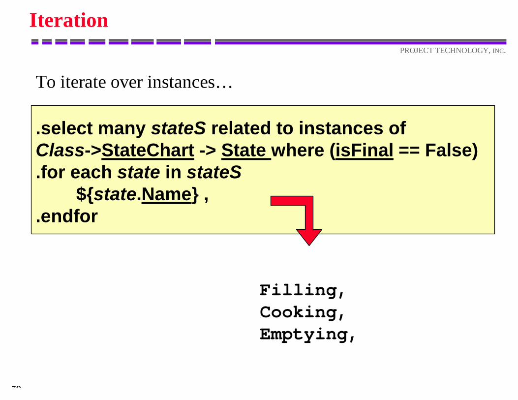
Iteration
To iterate over instances…
.select many stateS related to instances ofClass->StateChart -> State where (isFinal == False).for each state in stateS ${state.Name} ,.endfor
Filling,Cooking,Emptying,
79
PROJECT TECHNOLOGY, INC.
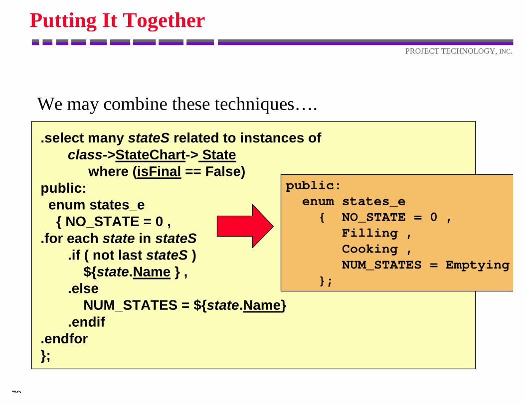
Putting It Together
We may combine these techniques… .
.select many stateS related to instances of class->StateChart-> State
where (isFinal == False)public: enum states_e { NO_STATE = 0 ,.for each state in stateS .if ( not last stateS ) ${state.Name } , .else NUM_STATES = ${state.Name} .endif.endfor};
public: enum states_e { NO_STATE = 0 , Filling , Cooking , NUM_STATES = Emptying };
80
PROJECT TECHNOLOGY, INC.
Application Semantics
An archetype language gives access toF the semantics of the applicationF as stored in the repository.
We may use the archetype language to generate code.
ADirect
Translation
82
PROJECT TECHNOLOGY, INC.
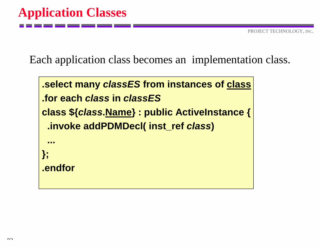
Application Classes
Each application class becomes an implementation class.
.select many classES from instances of class
.for each class in classESclass ${class.Name} : public ActiveInstance { .invoke addPDMDecl( inst_ref class) ...};.endfor
83
PROJECT TECHNOLOGY, INC.
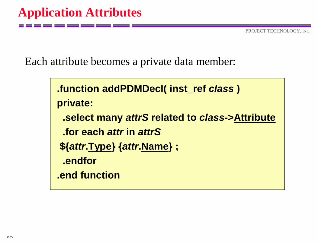
Application Attributes
Each attribute becomes a private data member:
.function addPDMDecl( inst_ref class )private:
.select many attrS related to class->Attribute .for each attr in attrS ${attr.Type} {attr.Name} ; .endfor
.end function
84
PROJECT TECHNOLOGY, INC.
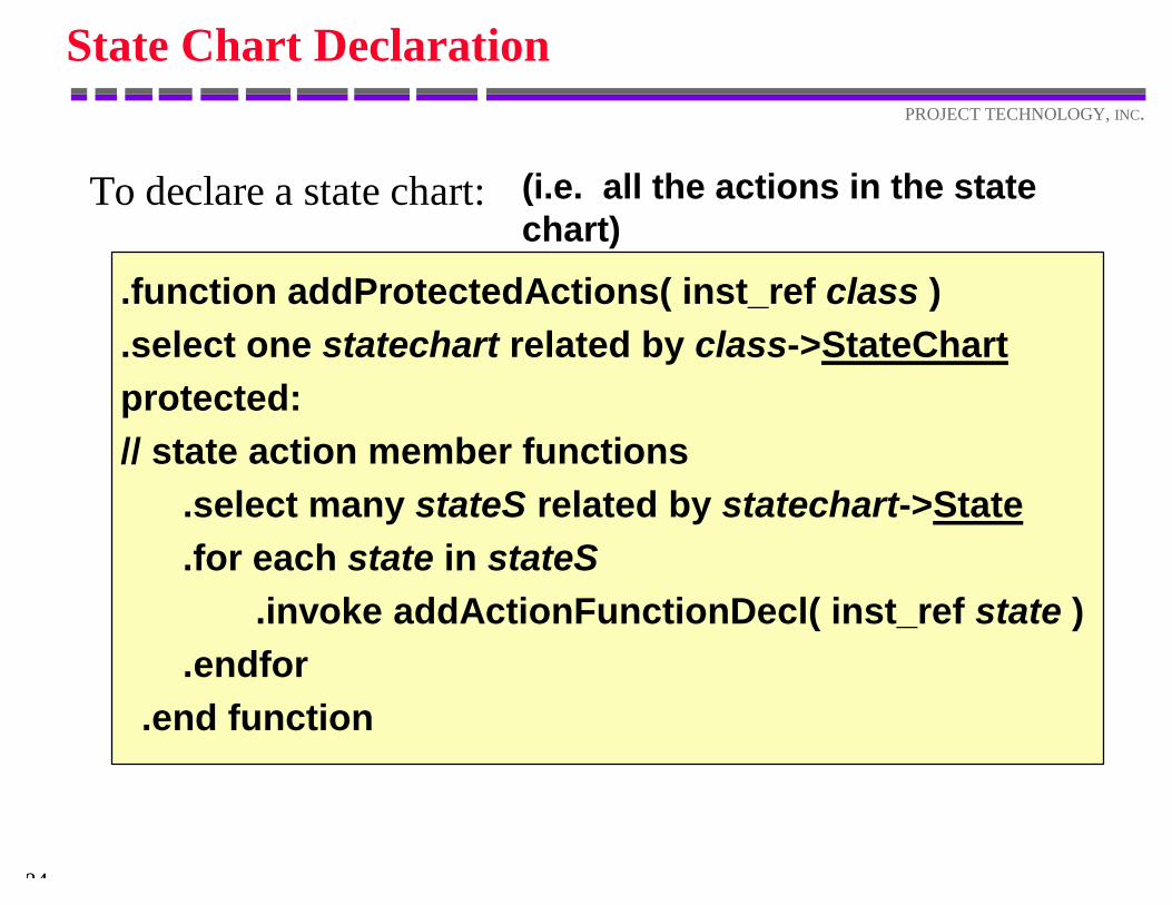
State Chart Declaration
To declare a state chart:
.function addProtectedActions( inst_ref class ) .select one statechart related by class->StateChart protected: // state action member functions .select many stateS related by statechart->State .for each state in stateS .invoke addActionFunctionDecl( inst_ref state ) .endfor .end function
(i.e. all the actions in the statechart)
85
PROJECT TECHNOLOGY, INC.
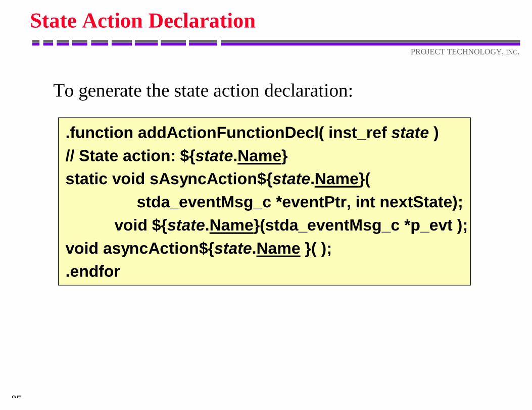
State Action Declaration
.function addActionFunctionDecl( inst_ref state )// State action: ${state.Name}static void sAsyncAction${state.Name}( stda_eventMsg_c *eventPtr, int nextState); void ${state.Name}(stda_eventMsg_c *p_evt );void asyncAction${state.Name }( );.endfor
To generate the state action declaration:
86
PROJECT TECHNOLOGY, INC.
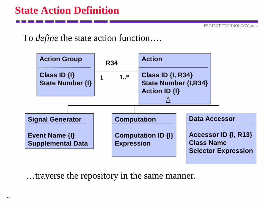
State Action Definition
To define the state action function… .
Signal Generator
Event Name {I}Supplemental Data
Data Accessor
Accessor ID {I, R13}Class NameSelector Expression
Action
Class ID {I, R34}State Number {I,R34}Action ID {I}
R34Action Group
Class ID {I}State Number {I}
Computation
Computation ID {I}Expression
1 1..*
… traverse the repository in the same manner.
Specifying the Architecture
88
PROJECT TECHNOLOGY, INC.
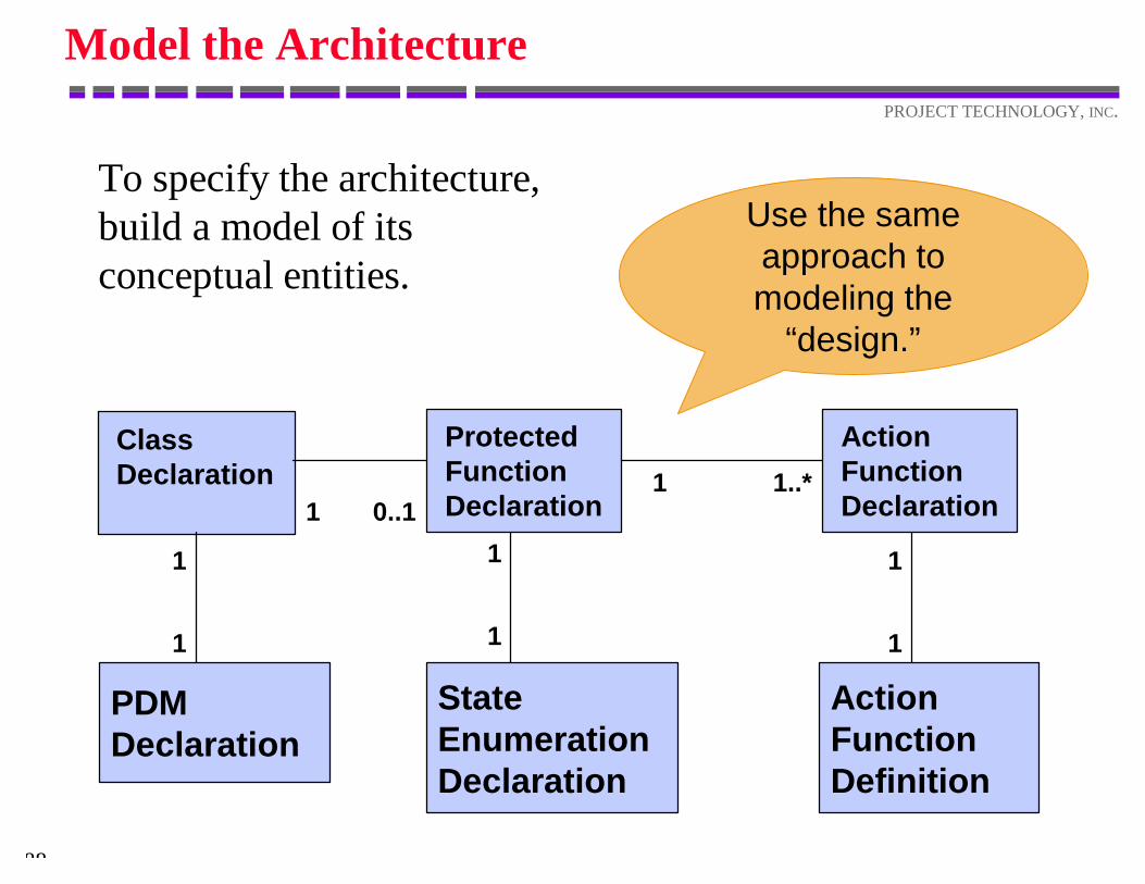
Model the Architecture
To specify the architecture,build a model of itsconceptual entities.
ProtectedFunction Declaration
ClassDeclaration
1 0..11 1..*
ActionFunctionDeclaration
PDMDeclaration
ActionFunctionDefinition
1
1
1
1
State EnumerationDeclaration
1
1
Use the sameapproach tomodeling the
“design.”
89
PROJECT TECHNOLOGY, INC.
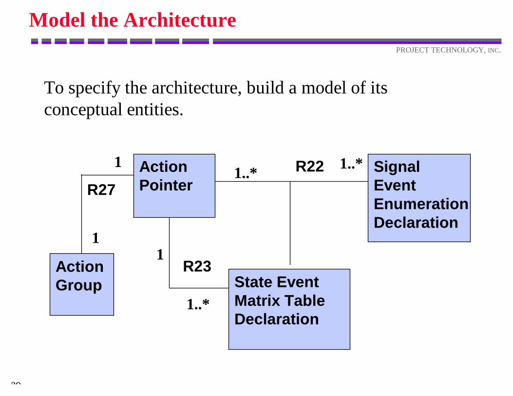
Model the Architecture
To specify the architecture, build a model of itsconceptual entities.
State EventMatrix TableDeclaration
ActionPointer
Signal Event EnumerationDeclaration
R22
R23
1..* 1..*
1
1..*
Action Group
1
1
R27
90
PROJECT TECHNOLOGY, INC.
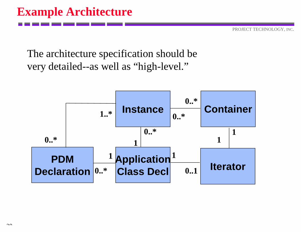
Example Architecture
The architecture specification should bevery detailed--as well as “high-level.”
ApplicationClass Decl
Instance
0..*1
PDMDeclaration
Container
Iterator1
0..* 0..1
1
0..*
0..*
11
1..*
0..*
91
PROJECT TECHNOLOGY, INC.
.Function addClassDeclaration
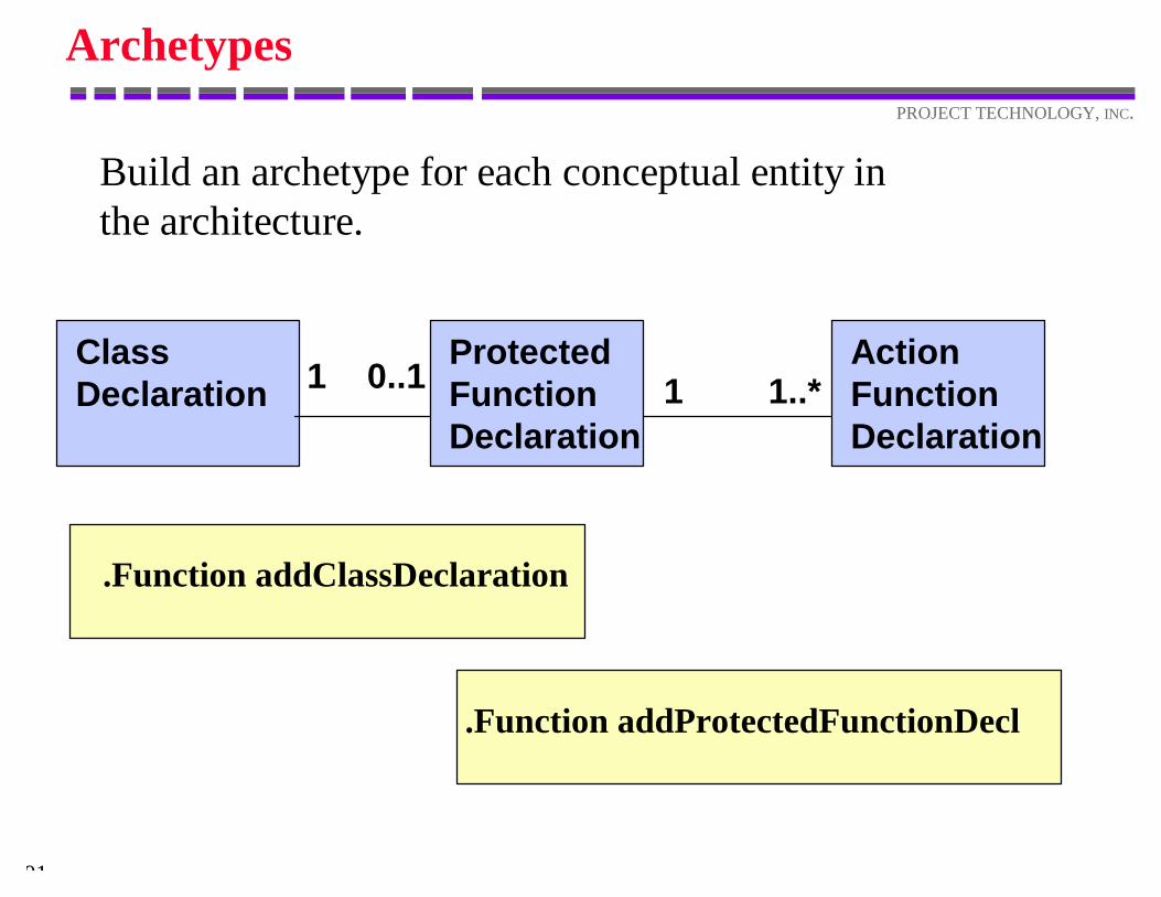
Archetypes
Build an archetype for each conceptual entity inthe architecture.
.Function addProtectedFunctionDecl
ProtectedFunction Declaration
ClassDeclaration 1 0..1 1 1..*
ActionFunctionDeclaration
92
PROJECT TECHNOLOGY, INC.
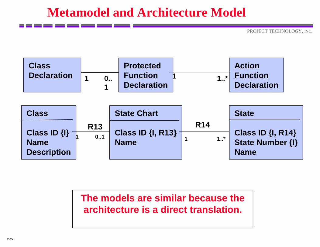
Metamodel and Architecture Model
The models are similar because thearchitecture is a direct translation.
ProtectedFunction Declaration
ClassDeclaration 1 0..
11 1..*
ActionFunctionDeclaration
State Chart
Class ID {I, R13}Name
Class
Class ID {I}NameDescription
R131 0..1
State
Class ID {I, R14}State Number {I}Name
1 1..*
R14
An Indirect Architecture
94
PROJECT TECHNOLOGY, INC.
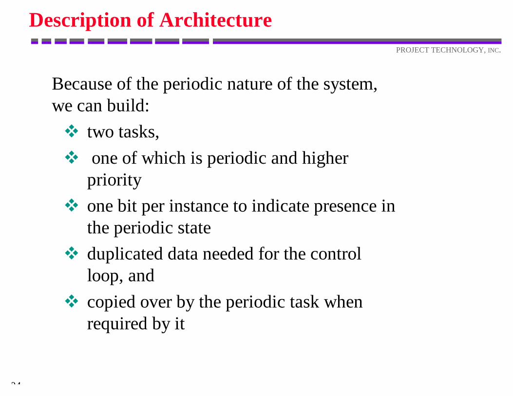
Description of Architecture
Because of the periodic nature of the system,we can build:v two tasks,v one of which is periodic and higher
priorityv one bit per instance to indicate presence in
the periodic statev duplicated data needed for the control
loop, andv copied over by the periodic task when
required by it
95
PROJECT TECHNOLOGY, INC.
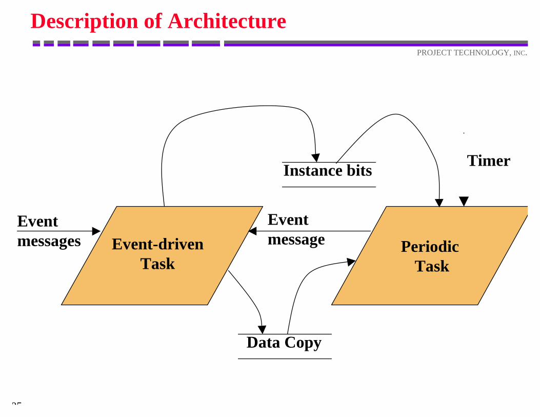
Description of Architecture
Periodic Task
Instance bits
Data Copy
Event-drivenTask
Eventmessage
Timer
Eventmessages
96
PROJECT TECHNOLOGY, INC.
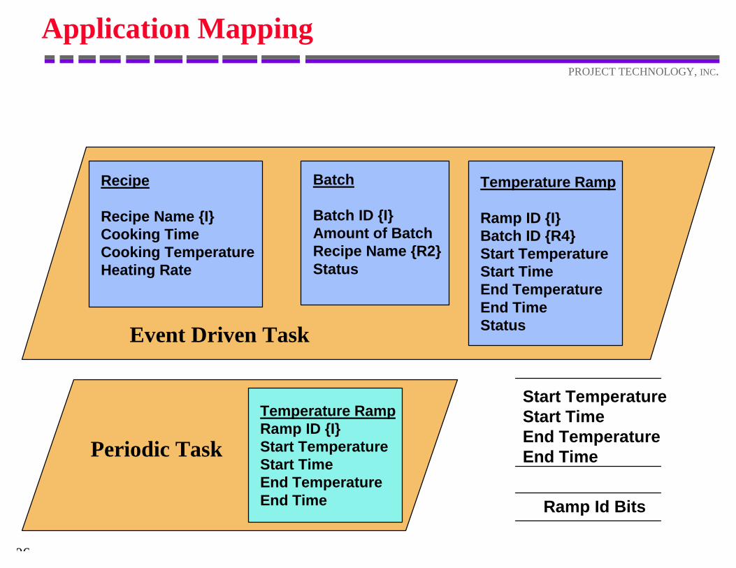
Application Mapping
Recipe
Recipe Name {I}Cooking TimeCooking TemperatureHeating Rate
Batch
Batch ID {I}Amount of BatchRecipe Name {R2}Status
Temperature Ramp
Ramp ID {I}Batch ID {R4}Start TemperatureStart TimeEnd TemperatureEnd TimeStatus
Temperature RampRamp ID {I}Start TemperatureStart TimeEnd TemperatureEnd Time
Start TemperatureStart TimeEnd TemperatureEnd Time
Ramp Id Bits
Event Driven Task
Periodic Task
97
PROJECT TECHNOLOGY, INC.
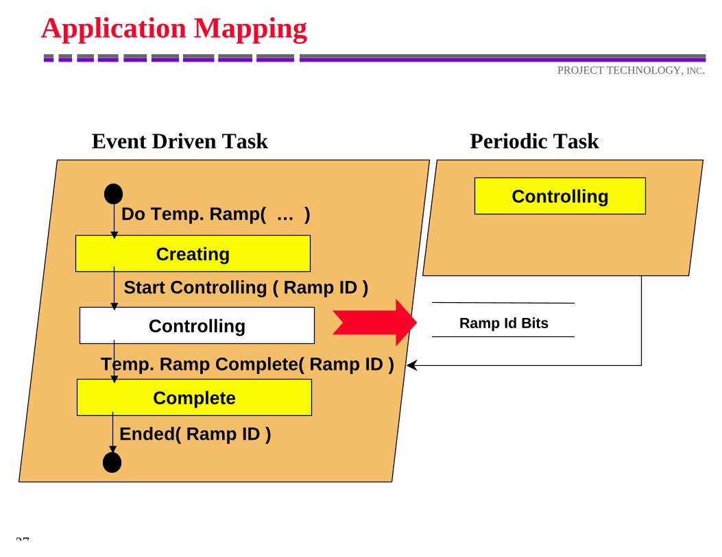
Application Mapping
Ramp Id Bits
Event Driven Task Periodic Task
Temp. Ramp Complete( Ramp ID )
Do Temp. Ramp( … )
Creating
Controlling
Complete
Start Controlling ( Ramp ID )
Ended( Ramp ID )
Controlling
98
PROJECT TECHNOLOGY, INC.
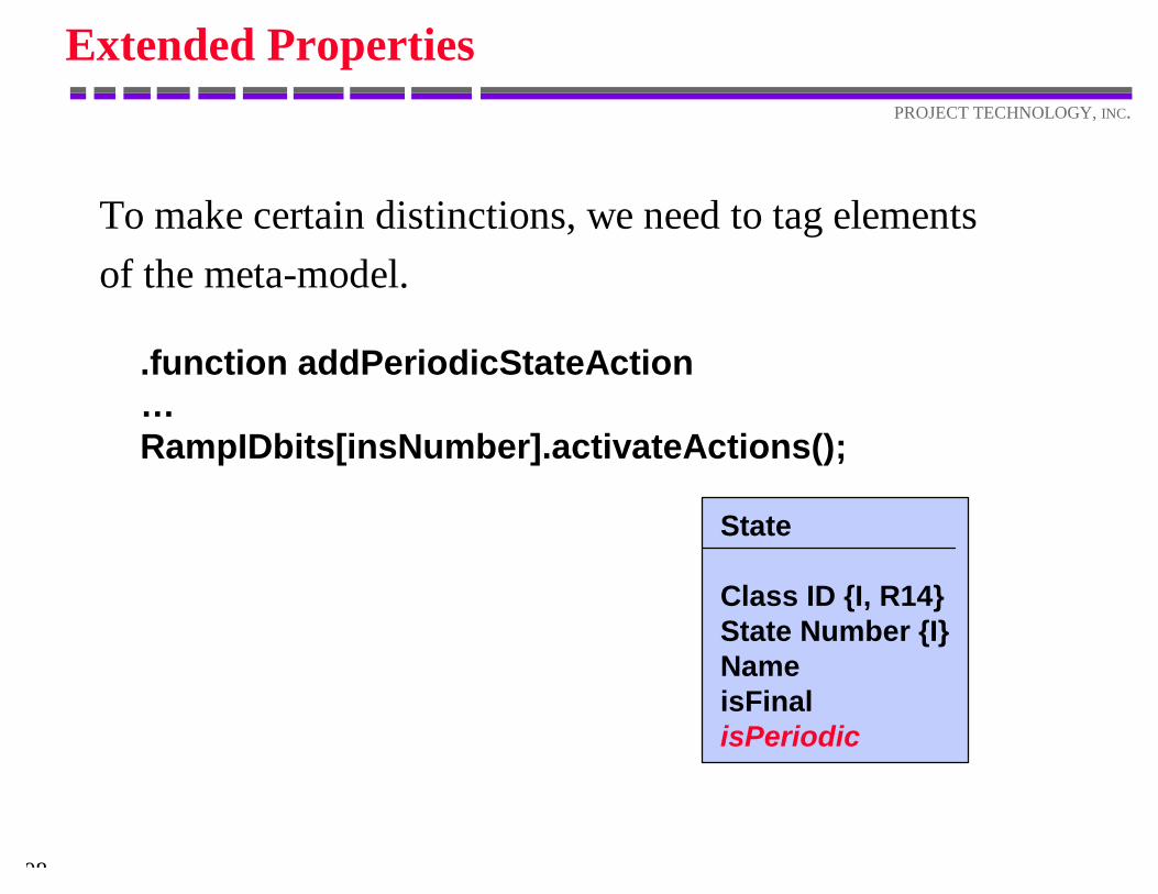
Extended Properties
To make certain distinctions, we need to tag elementsof the meta-model.
State
Class ID {I, R14}State Number {I}NameisFinalisPeriodic
.function addPeriodicStateAction…RampIDbits[insNumber].activateActions();
System Construction
100
PROJECT TECHNOLOGY, INC.
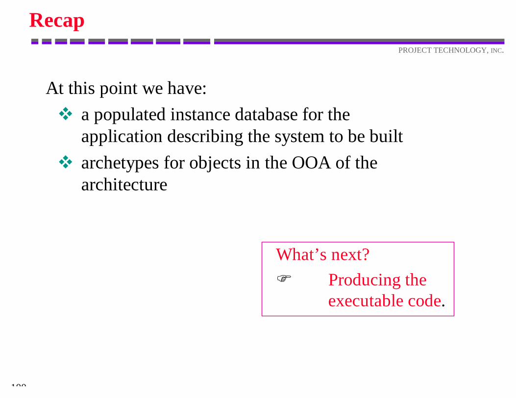
Recap
At this point we have:v a populated instance database for the
application describing the system to be builtv archetypes for objects in the OOA of the
architecture
What’s next?F Producing the
executable code.
101
PROJECT TECHNOLOGY, INC.
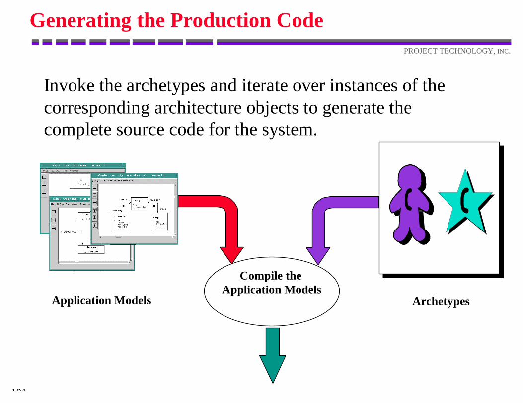
Generating the Production Code
Invoke the archetypes and iterate over instances of thecorresponding architecture objects to generate thecomplete source code for the system.
Compile theApplication Models
Application Models Archetypes
102
PROJECT TECHNOLOGY, INC.
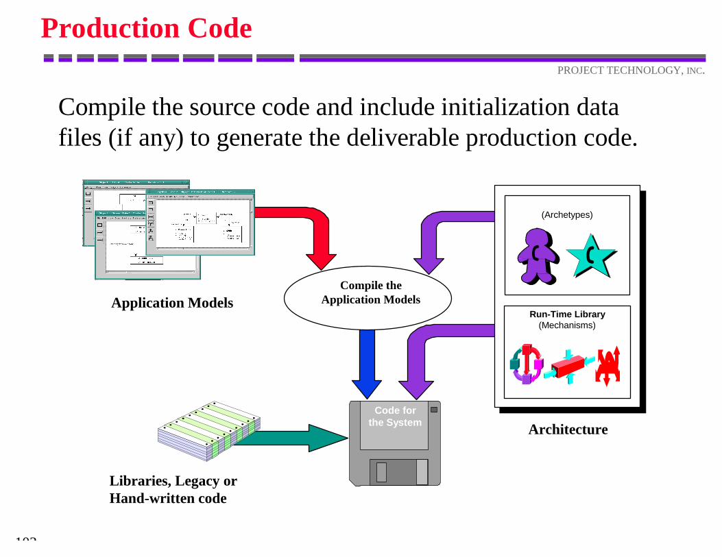
Production Code
Compile the source code and include initialization datafiles (if any) to generate the deliverable production code.
Application Models
Architecture
Compile theApplication Models
Code forthe System
Libraries, Legacy orHand-written code
Run-Time Library(Mechanisms)
(Archetypes)
103
PROJECT TECHNOLOGY, INC.
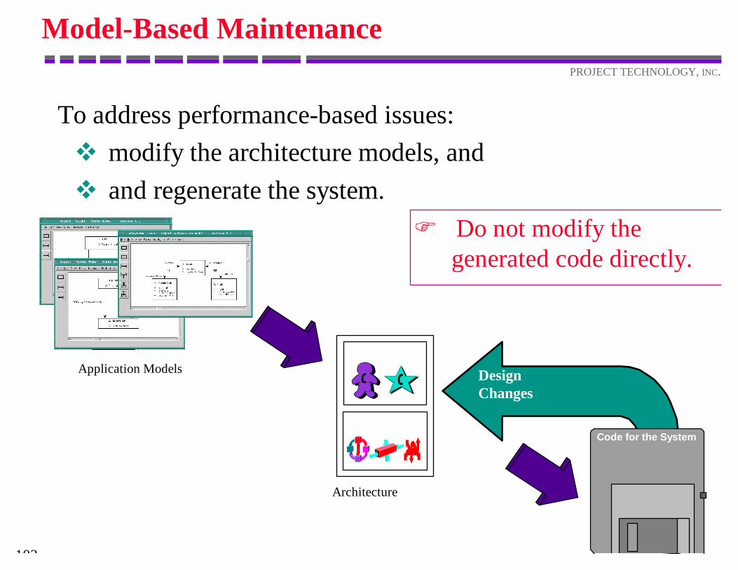
Model-Based Maintenance
To address performance-based issues:v modify the architecture models, andv and regenerate the system.
DesignChanges
Code for the System
Application Models
Architecture
F Do not modify the generated code directly.
104
PROJECT TECHNOLOGY, INC.
Application Changes
DesignChanges
Codefor theSystem
Application Models
Architecture
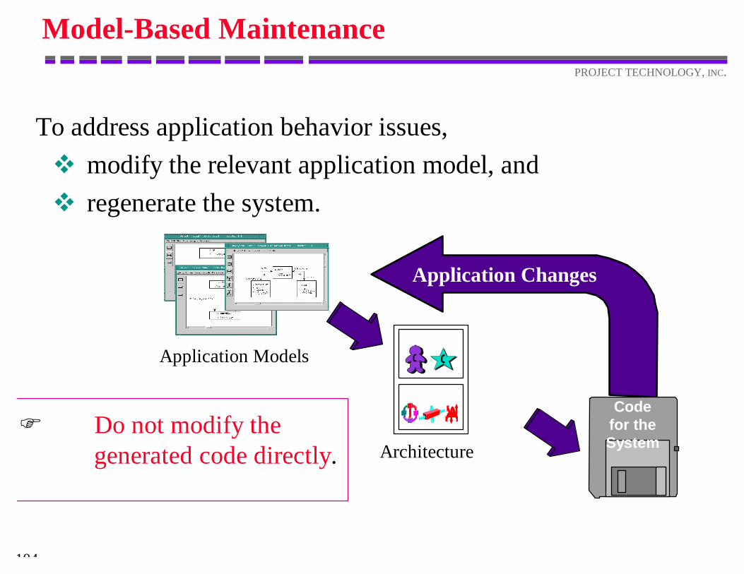
Model-Based Maintenance
To address application behavior issues,v modify the relevant application model, andv regenerate the system.
F Do not modify the generated code directly.
105
PROJECT TECHNOLOGY, INC.
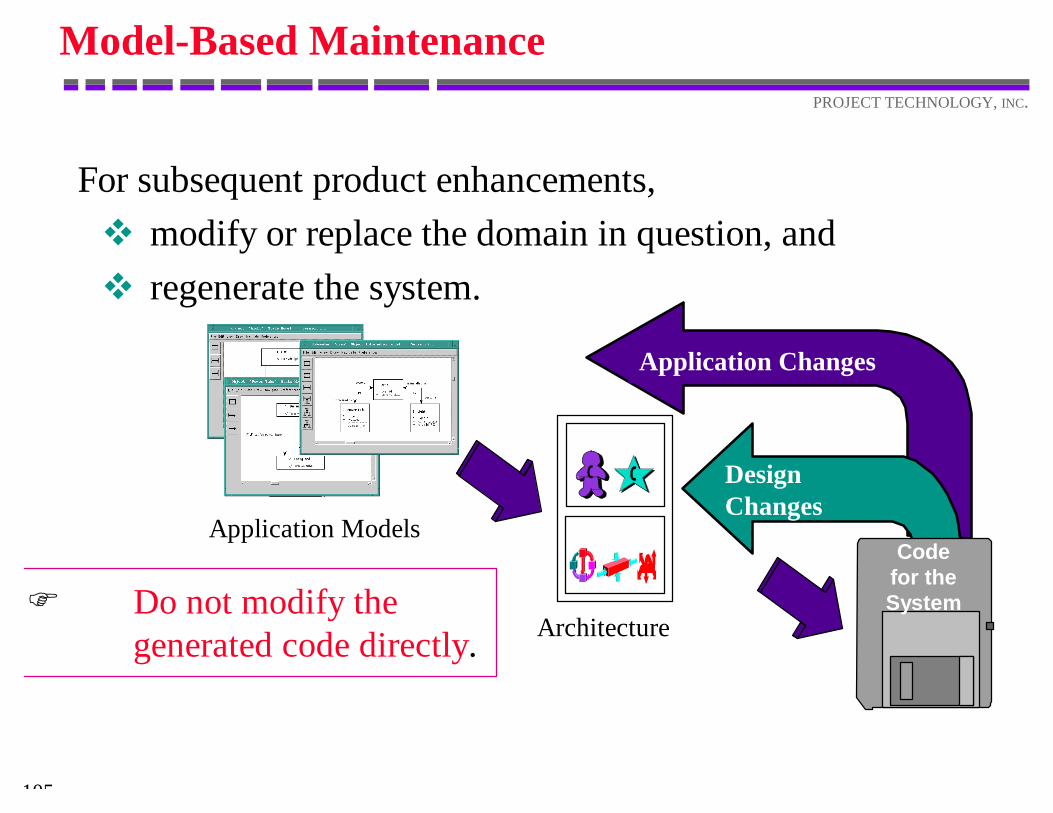
Model-Based Maintenance
For subsequent product enhancements,v modify or replace the domain in question, andv regenerate the system.
F Do not modify the generated code directly.
Application Changes
DesignChanges
Codefor theSystem
Application Models
Architecture
106
PROJECT TECHNOLOGY, INC.
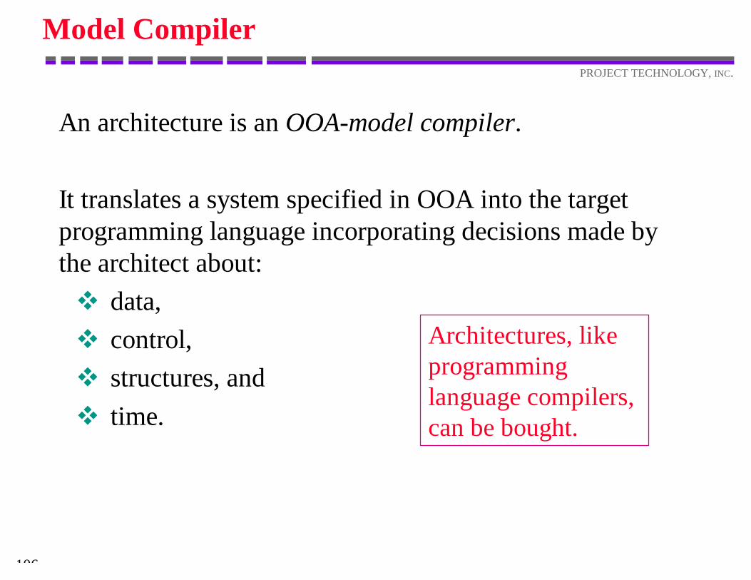
Model Compiler
An architecture is an OOA-model compiler.
It translates a system specified in OOA into the targetprogramming language incorporating decisions made bythe architect about:v data,v control,v structures, andv time.
Architectures, likeprogramminglanguage compilers,can be bought.
The Shlaer-Mellor Method
108
PROJECT TECHNOLOGY, INC.
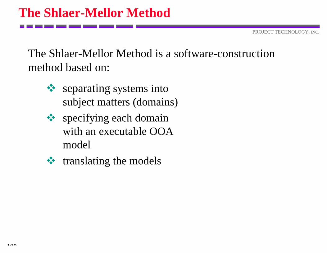
The Shlaer-Mellor Method
The Shlaer-Mellor Method is a software-constructionmethod based on:
v separating systems intosubject matters (domains)
v specifying each domainwith an executable OOAmodel
v translating the models
109
PROJECT TECHNOLOGY, INC.
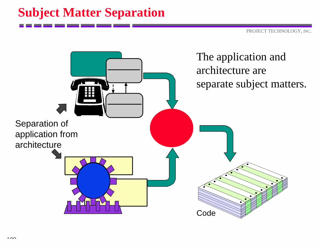
Subject Matter Separation
Separation ofapplication fromarchitecture
Code
The application andarchitecture areseparate subject matters.
110
PROJECT TECHNOLOGY, INC.
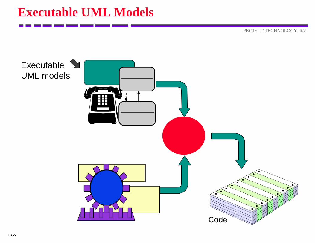
Executable UML Models
ExecutableUML models
Code
111
PROJECT TECHNOLOGY, INC.
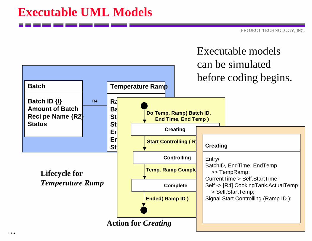
Executable UML Models
Executable modelscan be simulatedbefore coding begins.
Batch
Batch ID {I}Amount of BatchReci pe Name {R2}Status
Temperature Ramp
Ramp ID {I}Batch ID {R4}Start TemperatureStart TimeEnd TemperatureEnd TimeStatus
R4
Lifecycle for Temperature Ramp
Action for Creating
Do Temp. Ramp( Batch ID, End Time, End Temp )
Creating
Controlling
Complete
Start Controlling ( Ramp ID )
Temp. Ramp Complete( Ramp ID )
Ended( Ramp ID )
Creating
Entry/BatchID, EndTime, EndTemp >> TempRamp;CurrentTime > Self.StartTime;Self -> [R4] CookingTank.ActualTemp > Self.StartTemp;Signal Start Controlling (Ramp ID );
112
PROJECT TECHNOLOGY, INC.
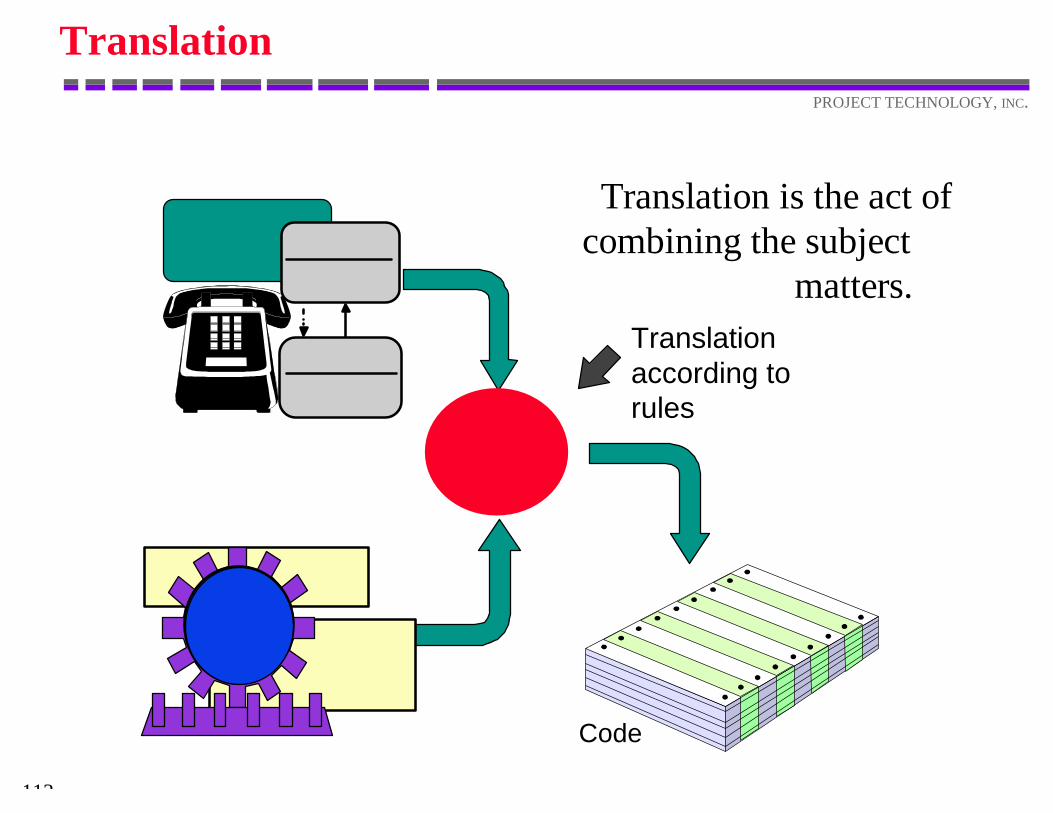
Translation
Translation is the act ofcombining the subject
matters.
Code
Translationaccording torules
113
PROJECT TECHNOLOGY, INC.
Translation
Translating the application domain models generates:v highly systematicv uniformv reproduciblev understandable application code
and minimizes:v coding and code inspection effortv coding errorsv component integration issues
114
PROJECT TECHNOLOGY, INC.
Shlaer-Mellor Method
The Shlaer-Mellor Method meets the challenges ofreal-time software development by:v localizing critical software design issues to
the software architecture domainv ensuring that the design decisions are
incorporated uniformly and systematicallyv providing a framework to modify system
performance without affecting systembehavior
115
PROJECT TECHNOLOGY, INC.
System Design: Architectures and Archetypes
This tutorial showed you how to:v identify the characteristics of the problem that
determine the system design;v engineer the system-wide design to meet
performance constraints;v model the system-wide design— the software
architecture;v build archetypes to produce efficient code.

116
PROJECT TECHNOLOGY, INC.