Embed Size (px)
Citation preview
PRIMERGY
System board D2532 for RX100 S4 Technical ManualDäschleinFujitsu Siemens Computers GmbH München81730 Muniche-mail: email: [email protected].: (089) 61001-155Fax: (++49) 700 / 372 00000D2532 (RX100 S4)Sprachen: En
Edition April 2007

Comments… Suggestions… Corrections…The User Documentation Department would like toknow your opinion of this manual. Your feedback helpsus optimize our documentation to suit your individual needs.
Fax forms for sending us your comments are included inthe back of the manual.
There you will also find the addresses of the relevantUser Documentation Department.
Certified documentation according to DIN EN ISO 9001:2000To ensure a consistently high quality standard anduser-friendliness, this documentation was created tomeet the regulations of a quality management system which complies with the requirements of the standardDIN EN ISO 9001:2000.
cognitas. Gesellschaft für Technik-Dokumentation mbHwww.cognitas.de
Copyright and TrademarksCopyright © 2006 Fujitsu Siemens Computers GmbH.
All rights reserved.Delivery subject to availability; right of technical modifications reserved.
All hardware and software names used are trademarks of their respective manufacturers.

D2532 (RX100 S4)
Contents1 Introduction . . . . . . . . . . . . . . . . . . . . . . . . . . . 5
2 Important notes . . . . . . . . . . . . . . . . . . . . . . . . . 72.1 Notes on safety . . . . . . . . . . . . . . . . . . . . . . . . . . 72.2 CE Certificate . . . . . . . . . . . . . . . . . . . . . . . . . . 102.3 Environment Protection . . . . . . . . . . . . . . . . . . . . . 11
3 Features . . . . . . . . . . . . . . . . . . . . . . . . . . . . 133.1 Overview . . . . . . . . . . . . . . . . . . . . . . . . . . . . 133.2 Main memory . . . . . . . . . . . . . . . . . . . . . . . . . . 153.3 PCI bus . . . . . . . . . . . . . . . . . . . . . . . . . . . . . 153.4 Screen resolution . . . . . . . . . . . . . . . . . . . . . . . . 163.5 Temperature / system monitoring . . . . . . . . . . . . . . . . 163.6 Connectors and jumpers . . . . . . . . . . . . . . . . . . . . 183.6.1 External connectors . . . . . . . . . . . . . . . . . . . . . . . 21
4 SAS/IME configuration program . . . . . . . . . . . . . . . 23
5 Replacing the lithium battery . . . . . . . . . . . . . . . . . 33
Abbreviations . . . . . . . . . . . . . . . . . . . . . . . . . . . . . . . 35


D2532 (RX100 S4) 5
1 IntroductionThis technical manual describes the system board D2532, which can be equipped with one Intel® processor.
You will find further information in the manual "BIOS Setup".
Further information about drivers is provided in the readme files on the supplied ServerView Bundle DVDs or CDs.
Notational conventions
The meanings of the symbols and fonts used in this manual are as follows:
italics indicates commands, menu items, file and path names or software programs
fixed font indicate system output on the monitor
semi-bold fixed font
indicates values to be entered through the keyboard
[Key symbol] indicates keys according to their representation on the keyboard
If capital letters are to be entered explicitly, then the Shift key is shown, e.g. [SHIFT] - [A] for A.
If two keys need to be pressed at the same time, then this is shown by placing a hyphen between the two key symbols.
“quotation marks” indicates names and terms that are being empha-sized.
Ê indicates an operation that to be performed
V CAUTION! indicates warnings, which, if ignored, will endanger your health, destroy the system or lead to the loss of data.
I indicates additional information, notes and tips
Table 1: Notational conventions


D2532 (RX100 S4) 7
2 Important notesIn this chapter you will find essential information regarding safety when handling the system board.
V CAUTION!
With the system board installed you must open the system to access the system board. How to access the system board of your system is described in the appropriate service supplement.
When handling the system board, refer to the specific notes on safety in the operating manual and/or service supplement for the respective server.
2.1 Notes on safety
V CAUTION!
● The actions described in these instructions should only be performed by authorized, qualified personnel. Equipment repairs should only be performed by qualified staff. Any failure to observe the guidelines in this manual, and any unauthorized openings and improper repairs could expose the user to risks (electric shock, fire hazards) and could also damage the equipment. Please note that any unauthorized openings of the device will result in the invalidation of the warranty and exclusion from all liability.
● Transport the device only in the antistatic original packaging or in packaging that protects it from knocks and jolts.
● Only install expansions that are allowed for the system board. If you install other expansions, you may damage the requirements and rules governing safety and electromagnetic compatibility or your system. Information on which system expansions are suitable can be obtained from the customer service centre or your sales outlet.
● The warranty expires if the device is damaged during the installation or replacement of system expansions.

8 D2532 (RX100 S4)
Notes on safety Important notes
V ● Components can become very hot during operation. Ensure you do not touch components when making extensions to the system board. There is a danger of burns!
● Transmission lines to peripheral devices must be adequately shielded.
● To the LAN wiring the requirements apply in accordance with the standards EN 50173 and EN 50174-1/2. As minimum requirement the use of a protected LAN line of category 5 for 10/100 MBps Ethernet, and/or of category 5e for Gigabit Ethernet is considered. The requirements of the specification ISO/IEC 11801 are to be considered.
● Never connect or disconnect data transmission lines during a storm (lightning hazard).
Batteries
V CAUTION!
● Incorrect replacement of lithium battery may lead to a risk of explosion. The batteries may only be replaced with identical batteries or with a type recommended by the manufacturer.
It is essential to observe the instructions in chapter “Replacing the lithium battery”.
D2532 (RX100 S4) 9
Important notes Notes on safety
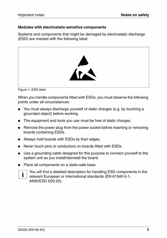
Modules with electrostatic-sensitive components
Systems and components that might be damaged by electrostatic discharge (ESD) are marked with the following label:
Figure 1: ESD label
When you handle components fitted with ESDs, you must observe the following points under all circumstances:
● You must always discharge yourself of static charges (e.g. by touching a grounded object) before working.
● The equipment and tools you use must be free of static charges.
● Remove the power plug from the power socket before inserting or removing boards containing ESDs.
● Always hold boards with ESDs by their edges.
● Never touch pins or conductors on boards fitted with ESDs.
● Use a grounding cable designed for this purpose to connect yourself to the system unit as you install/deinstall the board.
● Place all components on a static-safe base.
I You will find a detailed description for handling ESD components in the relevant European or international standards (EN 61340-5-1, ANSI/ESD S20.20).
10 D2532 (RX100 S4)
CE Certificate Important notes
Notes about boards
● During installation/deinstallation of the system board, observe the specific instructions described in the service manual for the server.
● Remove the plug from the mains outlet so that system and system board are totally disconnected from the mains voltage.
● To prevent damage to the system board, the components and conductors on it, please take great care when you insert or remove boards. Take great care to ensure that extension boards are slotted in straight, without damaging components or conductors on the system board, or any other components, for example EMI spring contacts
● Be careful with the locking mechanisms (catches, centring pins etc.) when you replace the system board or components on it, for example memory modules or processors.
● Never use sharp objects (screwdrivers) for leverage.
2.2 CE Certificate
The shipped version of this board complies with the requirements of the EEC directive 89/336/EEC „Electromagnetic compatibility“.
Compliance was tested in a typical PRIMERGY configuration.

D2532 (RX100 S4) 11
Important notes Environment Protection
2.3 Environment Protection
Environmentally-friendly product design and development
This product has been designed in accordance with the Fujitsu Siemens Computers standard for “environmentally friendly product design and devel-opment”. This means that key factors such as durability, selection and labeling of materials, emissions, packaging, ease of disassembly and recycling have been taken into account.
This saves resources and thus reduces the harm done to the environment.
Notes on saving energy
Devices that do not have to be on permanently should not be switched on until they need to be used and should be switched off during long breaks and on completion of work
Notes on packaging
Please do not throw away the packaging. You may need it later for transporting your system unit. If possible, the device should only be transported in its original packaging.
Notes on dealing with consumables
Please dispose of printer consumables and batteries in accordance with local government regulations.
Do not throw batteries and accumulators into the household waste. They must be disposed of in accordance with local regulations concerning special waste.
All batteries containing pollutants are marked with a symbol (a crossed-out rubbish bin on wheels). In addition, the marking is provided with the chemical symbol of the heavy metal decisive for the classification as a pollutant:
Cd CadmiumHg MercuryPb Lead
12 D2532 (RX100 S4)
Environment Protection Important notes
Notes on labeling plastic housing parts
Please avoid attaching your own labels to plastic housing parts wherever possible, since this makes it difficult to recycle them.
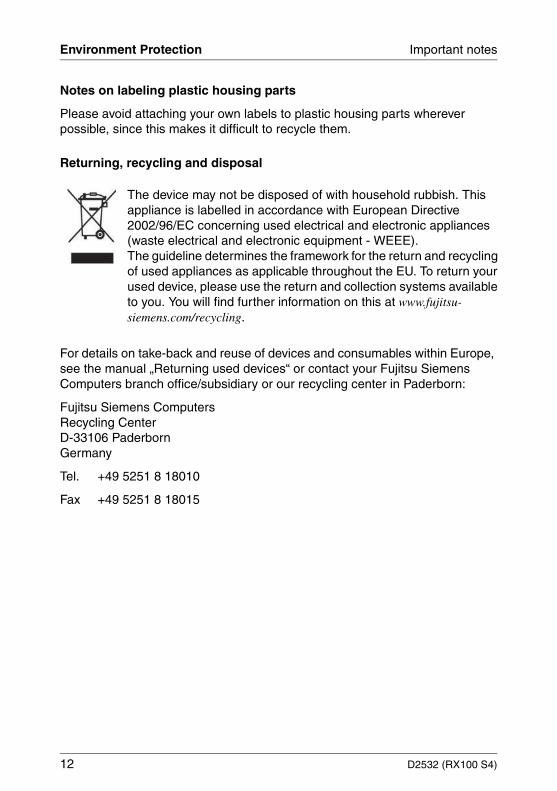
Returning, recycling and disposal
For details on take-back and reuse of devices and consumables within Europe, see the manual „Returning used devices“ or contact your Fujitsu Siemens Computers branch office/subsidiary or our recycling center in Paderborn:
Fujitsu Siemens ComputersRecycling CenterD-33106 Paderborn Germany
Tel. +49 5251 8 18010
Fax +49 5251 8 18015
The device may not be disposed of with household rubbish. This appliance is labelled in accordance with European Directive 2002/96/EC concerning used electrical and electronic appliances (waste electrical and electronic equipment - WEEE).The guideline determines the framework for the return and recycling of used appliances as applicable throughout the EU. To return your used device, please use the return and collection systems available to you. You will find further information on this at www.fujitsu-siemens.com/recycling.

D2532 (RX100 S4) 13
3 Features
3.1 Overview
There are two versions of the system board D2532 with the part numbers S26361-D2532-A10 (SAS version) and S26361-D2532-B10 (SATA version). The two versions differ in the chipset and connectors assembling.
System board
● One Intel® Celeron D, Pentium 4, Pentium D or Xeon processor with 533/800/1066 MHz Front Side Bus, socket 775
● Intel® chipset:– Intel® 3000 chipset.– Southbridge: Intel® ICH7R.– PXH-V.– SAS controller LSI 1068 (only SAS version).
● On optional riser card:– 2 x PCI-X (64 Bit / 133 MHz) slots or– 1 x PCI-Express x8 slot and 1 x PCI-X (64 Bit / 133 MHz) slot
● Dual Gigabit LAN controller: Broadcom 5715
● iRMC onboard Server Management and graphic controller
Main memory
– Up to 4 slots for main memory DDR II 533 (PC2-4200) SDRAM unbuf-fered.
– Memory modules for 512 MB, 1 GB and 2 GB.
– Maximum 8 Gbyte of memory.
– Supports dual-channel DDR2 interface with interleaved mode.
– Supports ECC (Error Correction Code).

14 D2532 (RX100 S4)
Overview Features
External connectors
– Front side (front panel):1x USB 2.0 port
– Rear side (I/O shield):2x USB 2.0 ports1x VGA port (15 pin)1x keyboard port1x mouse port1x RS-232-C interface (serial 9 pin)2x RJ45 LAN ports (onboard LAN)
BIOS features
– Phoenix BIOS
– Power on self-test
– System boot possible from:– CD/DVD-ROM– hard disk– LAN– USB
– CMOS setup parameters
– Shadow RAM BIOS
– Shadow video BIOS
– IPMI V2.0 support
– DMI function support
– System security: Power-on Password and Setup Password
Form factor
260 mm x 305 mm
D2532 (RX100 S4) 15
Features Main memory
3.2 Main memory
The four slots for the main memory are suitable for unbuffered DDR II 533 (PC2-4200) SDRAM memory modules. The organization in two memory banks, 1 and 2, permits rapid memory access with two-way interleaving.
I You will find the descriptions how to install memory modules in the Opttion Guide of your server.
3.3 PCI bus
PCI slots
Two riser cards are available. The following tables show an overview of the PCI slots:
Riser card 1:
Riser card 2:
Assignment of the PCI interrupts
The PCI interrupts are assigned automatically by the BIOS and no further settings are possible.
PCI bus Signal level
Slot no. Length
PCI-E x8 1 1x low profile or standard slot, max. length 175 mm
64 Bit/133 MHz (PCI-X) 3.3 V 2 1x low profile slot, max. length 170 mm
PCI bus Signal level
Slot no. Length
64 Bit/133 MHz (PCI-X) 3.3 V 1 1x low profile or standard slot, max. length 175 mm
64 Bit/133 MHz (PCI-X) 3.3 V 2 1x low profile slot, max. length 170 mm
16 D2532 (RX100 S4)
Screen resolution Features
3.4 Screen resolution
Depending on the operating system used the screen resolutions in the following table refer to the screen controller on the system board. If you are using an external screen controller, you will find details of supported screen resolutions in the operating manual or technical manual supplied with the controller.
3.5 Temperature / system monitoring
Temperature and system monitoring aim to reliably protect the computer hardware against damage caused by overheating. In addition, any unnecessary noise is also prevented by reducing the fan speed, and information is provided about the system status.
The temperature and system monitoring are controlled by an onboard controller.
The following functions are supported:
Temperature monitoring
Measurement of the processor temperature, measurement of the ambient temperature by a temperature sensor.
Fan monitoring
Fans that are blocked or sticky are detected.
Fan control
The fans are regulated according to temperature.
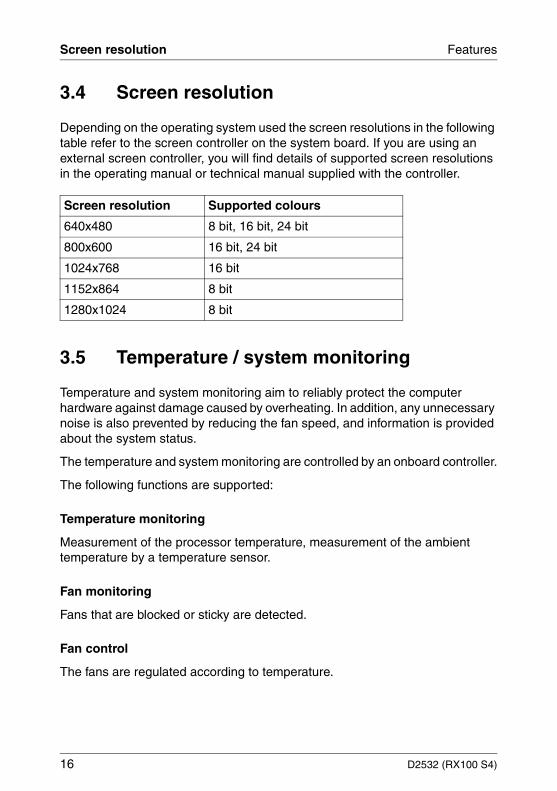
Screen resolution Supported colours
640x480 8 bit, 16 bit, 24 bit
800x600 16 bit, 24 bit
1024x768 16 bit
1152x864 8 bit
1280x1024 8 bit

D2532 (RX100 S4) 17
Features Temperature / system monitoring
Sensor monitoring
A fault in a temperature sensor is detected. Should this happen all fans monitored by this sensor run at maximum speed, to achieve the greatest possible protection of the hardware.
Voltage monitoring
When voltage exceeds warning level high an alert will be generated.
System Event Log (SEL)
All monitored events of the system board are recorded in the System Event Log.
18 D2532 (RX100 S4)
Connectors and jumpers Features
3.6 Connectors and jumpers
There are two versions of the system board D2532 with the part numbers S26361-D2532-A10 (SAS version) and S26361-D2532-B10 (SATA version).
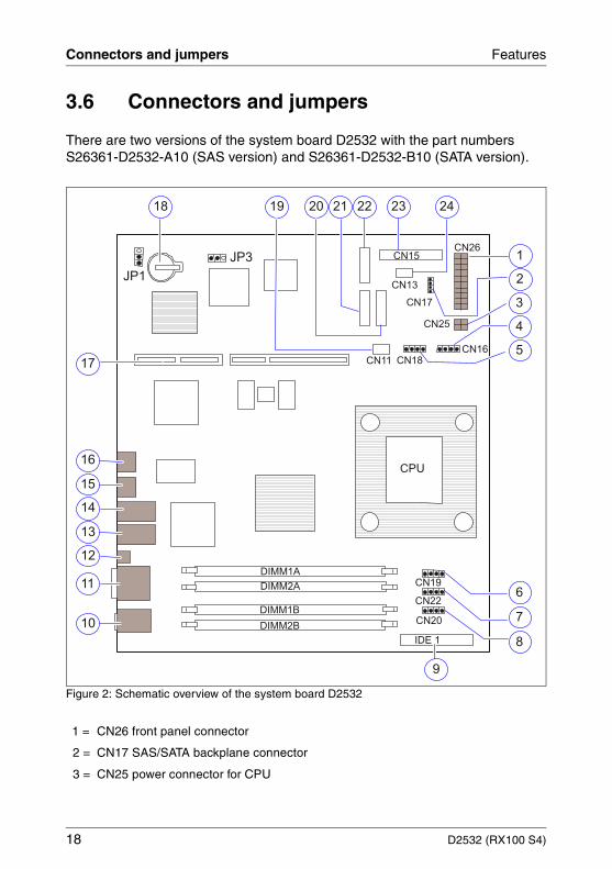
Figure 2: Schematic overview of the system board D2532
1 = CN26 front panel connector
2 = CN17 SAS/SATA backplane connector
3 = CN25 power connector for CPU
1
CPU
DIMM2B
DIMM1B
DIMM2A
DIMM1A
JP3CN26
CN25
IDE 1
CN20
JP1
3
4
5
6
7
8
9
14
13
12
11
10
16
15
17
19 21 22 2320
CN22
CN19
CN18
CN16
CN13
CN17
CN11
CN15
24
2
18

D2532 (RX100 S4) 19
Features Connectors and jumpers
4 = CN16 system fan 5 connector
5 = CN18 system fan 4 connector
6 = CN19 system fan 3 connector
7 = CN22 system fan 2 connector
8 = CN20 system fan 1 connector
9 = IDE 1 connector
10 = Mouse/keyboard connector
11 = VGA/COM1 connector
12 = Global Error LED/Identifications LED
13 = LAN 1 connector (Server Management LAN)
14 = LAN 2 connector
15 = USB connector
16 = USB connector
17 = Slot for riser card
18 = Battery
19 = CN11 SATA BP LED connector
20 = SAS/SATA 2 connector
21 = SAS/SATA 1 connector
22 = SATA 3 connector (only SATA version)
23 = CN12 PSU I2C connector
24 = CN11 PSU ATX connector

20 D2532 (RX100 S4)
Connectors and jumpers Features
Settings with jumpers
The system board is supplied with all jumpers set on the following positions.
Figure 3: Jumper default settings
JP1 - Boot Block
JP3 - Password Skip
1-2 Normal boot (default)
2-3 BIOS recovery
1-2 Disable (default)
2-3 Enable
JP3CN26
CN25
JP1CN13
CN17
CN15
D2532 (RX100 S4) 21
Features Connectors and jumpers
3.6.1 External connectors
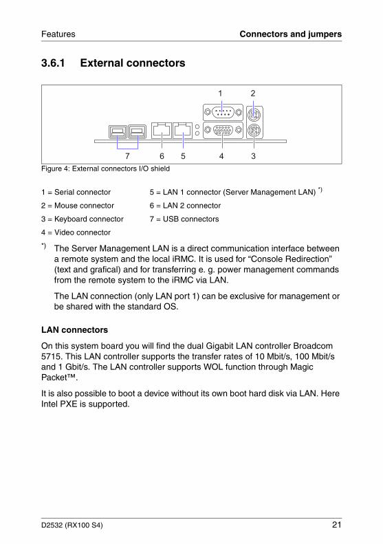
Figure 4: External connectors I/O shield
*) The Server Management LAN is a direct communication interface between a remote system and the local iRMC. It is used for “Console Redirection” (text and grafical) and for transferring e. g. power management commands from the remote system to the iRMC via LAN.
The LAN connection (only LAN port 1) can be exclusive for management or be shared with the standard OS.
LAN connectors
On this system board you will find the dual Gigabit LAN controller Broadcom 5715. This LAN controller supports the transfer rates of 10 Mbit/s, 100 Mbit/s and 1 Gbit/s. The LAN controller supports WOL function through Magic Packet™.
It is also possible to boot a device without its own boot hard disk via LAN. Here Intel PXE is supported.
1 = Serial connector 5 = LAN 1 connector (Server Management LAN) *)
2 = Mouse connector 6 = LAN 2 connector
3 = Keyboard connector 7 = USB connectors
4 = Video connector
2
7 56
1
4 3
22 D2532 (RX100 S4)
Connectors and jumpers Features
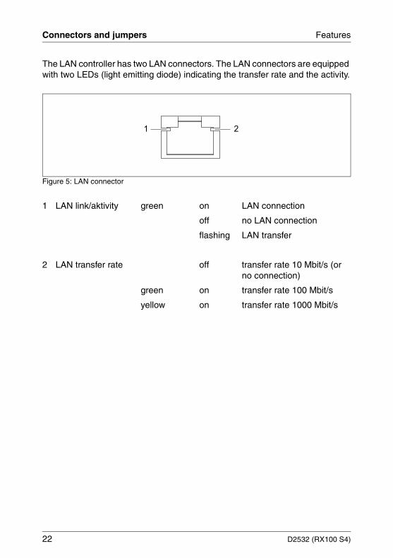
The LAN controller has two LAN connectors. The LAN connectors are equipped with two LEDs (light emitting diode) indicating the transfer rate and the activity.
Figure 5: LAN connector
1 LAN link/aktivity green on LAN connection
off no LAN connection
flashing LAN transfer
2 LAN transfer rate off transfer rate 10 Mbit/s (or no connection)
green on transfer rate 100 Mbit/s
yellow on transfer rate 1000 Mbit/s
1 2

4 SAS/IME configuration program For the SAS version the system board is equipped with an eight channel SAS controller 1068 from LSI Logic. The assignment of the SAS channels to the SAS connectors on the system board is as follows:
– channels 0 are connected to connector SAS/SATA1.
– channels 1 are connected to connector SAS/SATA2.
You will find the exact location of the SAS connector in the schematic view of the system board.
The BIOS of the onboard SAS controller includes a menu-driven SAS/IME (Integrated Mirror Enhanced) configuration program. This program allows you to change almost all of the option settings of the SAS controller.
When you boot the system a SAS-BIOS message listing the SAS devices connected is displayed.
I If a SAS-BIOS error message appears or problems arise with SAS devices, please read the documentation of your SAS device.
If you are unable to trace or rectify the error, please contact your dealer or our customer service centre.
Working with the keyboard
Use the following keys when running the program:
arrow keys to make selections
[+]/[-] to change a selection
[ENTER] to accept a selection
[ESC] to call the previous menu and to terminate the SAS configu-ration program
[F2] to jump into the menu line. This function is not available in all menus
D2532 (RX100 S4) 23

SAS/IME configuration program
Calling the SAS/IME configuration program
You will find more information about IME in the following manuals:– LSI Logic MegaRAID, SAS Software - User’s Guide– LSI Logic MegaRAID, SAS Device Driver - Installation– Integrated SAS for RAID - User’s Guide– Global Array Manager, Client Software - User’s Guide
Ê Start the PC, if the following message appears, press the key combination [CTRL] and [C]:
„Press Ctrl-C to start LSI Logic Configuration Utility“
Following hint appears next:
„Please wait, invoking LSI Logic Configuration Utility...“
In the first menu all available SAS controllers are displayed.
LSI Logic MPT Setup Utility Adapter List Global Properties ____________________________________________________________________________ Adapter PCI PCI PCI PCI FW Revision Status Boot Bus Dev FNC Slot Order SAS1068 02 08 00 00 1.10.01.00-IR Enabled 0 ____________________________________________________________________________ Esc = Exit Menu F1/Shift+1 = Help Alt+M = Global Properties +/- = Alter Boot Order Ins/Del = Alter Boot List
Terminating the SAS/IME configuration program
Depending on the current menu level, you can display the previous menu by pressing the [ESC] key. If you have made changes in the current menu you will be prompted to store them.
Ê To quit the configuration program press the [ESC] key until a corresponding message is displayed.
24 D2532 (RX100 S4)
SAS/IME configuration program
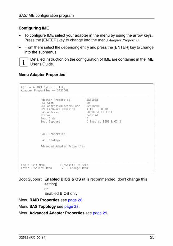
Configuring IME
Ê To configure IME select your adapter in the menu by using the arrow keys. Press the [ENTER] key to change into the menu Adapter Properties.
Ê From there select the depending entry and press the [ENTER] key to change into the submenus.
I Detailed instruction on the configuration of IME are contained in the IME User's Guide.
Menu Adapter Properties
LSI Logic MPT Setup Utility Adapter Properties -- SAS1068 ______________________________________________________________________________ Adapter Properties SAS1068 PCI Slot 00 PCI Address(Bus/dev/Func) 02:08:00 MPT Firmware Revision 1.10.01.00-IR SAS Address 5003005F:FFFFFFF0 Status Enabled Boot Order 0 Boot Support [ Enabled BIOS & OS ] RAID Properties SAS Topology Advanced Adapter Properties ______________________________________________________________________________ Esc = Exit Menu F1/Shift+1 = Help Enter = Select Item +/- = Change Item
Boot Support Enabled BIOS & OS (it is recommended: don’t change this setting) orEnabled BIOS only
Menu RAID Properties see page 26.
Menu SAS Topology see page 28.
Menu Advanced Adapter Properties see page 29.
D2532 (RX100 S4) 25

SAS/IME configuration program
Menu RAID Properties
In this menu you can start the RAID configuration menu.
LSI Logic MPT Setup Utility Select New Array Type -- SAS1068 ______________________________________________________________________________ View Existing Array View the existing configuration. Create IM Volume Create Integrated Mirror Array of 2 disks plus an optional hot spare. Data on the primary disk may be migrated. Create IME Volume Create Integrated Mirrored Enhanced Array of 3 to 8 disks including an optional hot spare. ALL DATA on array disks will be DELETED! Create IS Volume Create Integrated array of 2 to 8 disks. ALL DATA on array disks will be DELETED! ______________________________________________________________________________ Esc = Exit Menu F1/Shift+1 = Help Enter = Choose array type to create Esc = Return to Adapter Properties
26 D2532 (RX100 S4)
SAS/IME configuration program
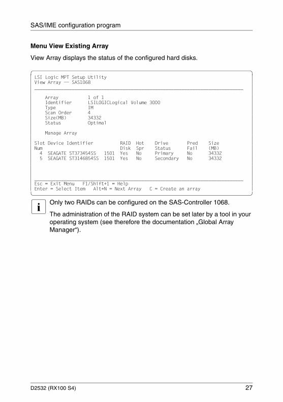
Menu View Existing Array
View Array displays the status of the configured hard disks.
LSI Logic MPT Setup Utility View Array -- SAS1068 ______________________________________________________________________________ Array 1 of 1 Identifier LSILOGICLogical Volume 3000 Type IM Scan Order 4 Size(MB) 34332 Status Optimal Manage Array Slot Device Identifier RAID Hot Drive Pred Size Num Disk Spr Status Fail (MB) 4 SEAGATE ST373454SS 1501 Yes No Primary No 34332 5 SEAGATE ST3146854SS 1501 Yes No Secondary No 34332 ______________________________________________________________________________ Esc = Exit Menu F1/Shift+1 = Help Enter = Select Item Alt+N = Next Array C = Create an array
I Only two RAIDs can be configured on the SAS-Controller 1068.
The administration of the RAID system can be set later by a tool in your operating system (see therefore the documentation „Global Array Manager“).
D2532 (RX100 S4) 27

SAS/IME configuration program
Menu SAS Topology
SAS Topology displays the allocations of the hard disks.
LSI Logic MPT Setup Utility SAS Topology -- SAS1068 ______________________________________________________________________________ Device Identifier Device SAS1068(02:08:00) Info I_ Enclosure Direct Attach Devices Controller I_ Bay 0 SEAGATE ST3146854SS 1501 SAS I_ Bay 1 SEAGATE ST336754SS 1501 SAS I_ Bay 2 SEAGATE ST336754SS 1501 SAS I_ Bay 4 RAID Physical Disk SAS I_ Bay 5 RAID Physical Disk SAS I_ IM VOL LSILOGICLogical Volume 3000 I_ SEAGATE ST373454SS 1501 I_ SEAGATE ST3146854SS 1501 ______________________________________________________________________________ Esc = Exit F1 = Help Alt+D = Device Properties Alt+M = More Keys
28 D2532 (RX100 S4)

SAS/IME configuration program
Menu Advanced Adapter Properties
LSI Logic MPT Setup Utility Advanced Adapter Properties -- SAS1068 ______________________________________________________________________________ IRQ 0B NUM Yes IO Port Address 3000 Chip Revision ID 01 CHS Mapping [SCSI Plug and Play Mapping] Advanced Device Properties Spinup Properties PHY Properties Restore Defaults ______________________________________________________________________________ Esc = Exit Menu F1/Shift+1 = Help Enter = Select Item -/+ = Change Item
CHS Mapping SCSI Plug and Play Mapping (it is recommended: don’t change this setting) orAlternate CHS Mapping
Menu Advanced Device Properties see page 30.
Menu Spinup Properties see page 31.
Menu PHY Properties see page 32.
D2532 (RX100 S4) 29
SAS/IME configuration program
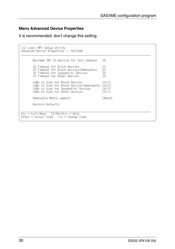
Menu Advanced Device Properties
It is recommended: don’t change this setting.
LSI Logic MPT Setup Utility Advanced Device Properties -- SAS1068 ______________________________________________________________________________ Maximum INT 13 devices for this adapter 24 IO Timeout for Block Devices 10 IO Timeout for Block Devices(Removable) 10 IO Timeout for Sequential Devices 10 IO Timeout for Other Devices 10 LUNs to Scan for Block Devices [All] LUNs to Scan for Block Devices(Removable) [All] LUNs to Scan for Sequential Devices [All] LUNs to Scan for Other Devices [All] Removable Media support [None] Restore Defaults ______________________________________________________________________________ Esc = Exit Menu F1/Shift+1 = Help Enter = Select Item -/+ = Change Item
30 D2532 (RX100 S4)
SAS/IME configuration program
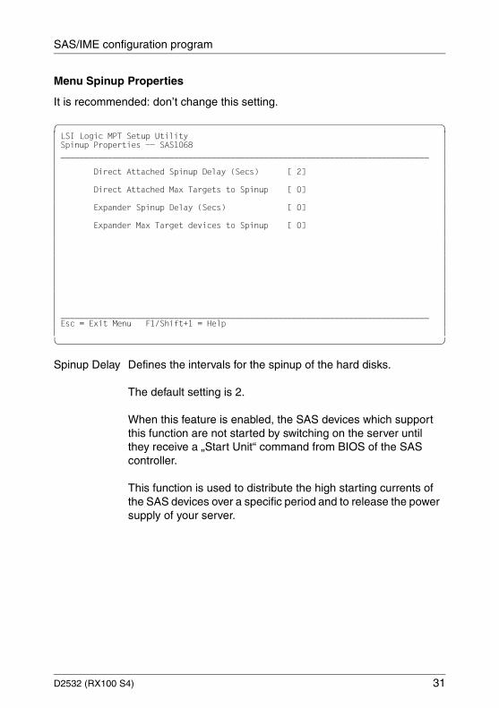
Menu Spinup Properties
It is recommended: don’t change this setting.
LSI Logic MPT Setup Utility Spinup Properties -- SAS1068 ______________________________________________________________________________ Direct Attached Spinup Delay (Secs) [ 2] Direct Attached Max Targets to Spinup [ 0] Expander Spinup Delay (Secs) [ 0] Expander Max Target devices to Spinup [ 0] ______________________________________________________________________________ Esc = Exit Menu F1/Shift+1 = Help
Spinup Delay Defines the intervals for the spinup of the hard disks.
The default setting is 2.
When this feature is enabled, the SAS devices which support this function are not started by switching on the server until they receive a „Start Unit“ command from BIOS of the SAS controller.
This function is used to distribute the high starting currents of the SAS devices over a specific period and to release the power supply of your server.
D2532 (RX100 S4) 31

SAS/IME configuration program
Menu PHY Properties
It is recommended: don’t change this setting.
LSI Logic MPT Setup Utility PHY Properties -- SAS1068 ______________________________________________________________________________ PHY 0 (1st of 8 PHYs) SAS Port 0 Link Status Enabled, 3.0 Gbps Discovery Status 000000 Device Identifier SEAGATE ST3146854SS 1501 Scan Order 0 Device Information SAS SAS Address 5000C500:0000EB39 ______________________________________________________________________________ Esc = Exit Menu F1/Shift+1 = Help Enter = Reset Phy error logs Alt+N = Next Phy Alt+P = Previous Phy
32 D2532 (RX100 S4)

D2532 (RX100 S4) 33
5 Replacing the lithium batteryIn order to save the system information permanently, a lithium battery is installed to provide the CMOS-memory with a current. When the charge is too low or the battery is empty, a corresponding error message is provided. The lithium battery must then be replaced.
V The lithium battery must be replaced with an identical battery or a battery type recommended by the manufacturer (CR2032).
Do not throw lithium batteries into the trashcan. It must be disposed of in accordance with local regulations concerning special waste.
Make sure that you insert the battery the right way round. The plus pole must be on the top!
Figure 6: Replacing the lithium battery (holder is similar)
Ê Press the locking spring into direction of of the arrow (1), so that the lithium- battery jumps out of its socket.
Ê Remove the battery (2).
Ê Insert a new lithium battery of the same type into the socket (3) and (4).
1
2
3
4


D2532 (RX100 S4) 35
AbbreviationsThe technical terms and abbreviations given below represent only a selection of the full list of common technical terms and abbreviations.
Not all technical terms and abbreviations listed here are valid for the described system board.
ACAlternating Current
ACPIAdvanced Configuration and Power management Interface
ANSIAmerican National Standards Institute
ASR&RAutomatic Server Recovery and Restart
ATAAdvanced Technology Attachment
BBUBattery Backup Unit
BIOSBasic Input Output System
BMCBaseboard Management Controller
CMOSComplementary Metal Oxide Semiconductor
COMCOMmunication port
CPUCentral Processing Unit

36 D2532 (RX100 S4)
Abbreviations
DDRDouble Data Rate
DIMMDual In-line Memory Module
DIPDual In-line Package
DMIDesktop Management Interface
DRAMDynamic Random Access Memory
ECCError Correction Code
EEPROMElectrical Erasable Programmable Read Only Memory
EFIExtensible Firmware Interface
EGBElektrostatisch gefährdete Bauteile
EMIElectromagnetic interference
EMRLEmbedded RAID Logic
EMVElektromagnetische Verträglichkeit (electromagnetic compatibility)
EPROMErasable Programmable Read Only Memory
ESDElectroStatic Discharge (elektrostatische Entladung)

D2532 (RX100 S4) 37
Abbreviations
EVRDEnterprise VRD
HPCHotplug Controller
FPCFront Panel Controller
FRUField Replaceable Unit
FSBFront Side Bus
ICEIn Circuit Emulation
IDEIntegrated (intelligent) Drive Electronics
IECInternational Electrotechnical Commission
IMEIntegrated Mirroring Enhanced
IOOPIntelligent Organisation Of PCI
IPMBIntelligent Platform Management Bus
IPMIIntelligent Platform Management Interface
iRMCintegrated Remote Management Controller
ISOInternational Organisation for Standardisation

38 D2532 (RX100 S4)
Abbreviations
LANLocal Area Network
LEDLight Emitting Diode
MPSMulti Processor Specification
NMINon Maskable Interrupt
OEMOriginal Equipment Manufacturer
OHCIOpen Host Controller Interface
OSOperating System
PCIPeripheral Components Interconnect
PDAPrefailure Detection and Analyzing
PIOProgrammed Input Output
PDBPower Distribution Board
PLDProgrammable Logic Device
PS(U)Power Supply (Unit)
PWMPulse Wide Modulation
D2532 (RX100 S4) 39
Abbreviations
PXEPreboot eXecution Environment
RAIDRedundant Array of Inexpensive Disks
RoHSRestriction of the Use of Certain Hazardous Substances (Waste from Electric and Electronic Equipment, EU Directive)
RoMBRAID on Motherboard
RSBRemote Service Board
RSTReSeT
RTCReal Time Clock
SASSerial Attached SCSI
SATASerial ATA
SCSISmall Computer Systems Interface
SDDCSingle Device Data Correction
SDRAMSynchronous Dynamic Random Access Memory
SELSystem Event Log
SHDGServer Hardware Design Guide
40 D2532 (RX100 S4)
Abbreviations
SMBSystem Management Bus
SMMServer Management Mode
SMPSymmetrical Multi Processing
UHCIUnified Host Controller Interface
USBUniversal Serial Bus
VGAVideo Graphics Adapter
VRDVoltage Regulator Down
VRMVoltage Regulator Module
WEEEWaste from Electric and Electronic Equipment (EU Directive)
WfMWired for Management
WOLWake up On LAN

Comments on System board D2532 for RX100 S4Technical manual
D2532 (RX100 S4)
CommentsSuggestionsCorrections
✁
Submitted by
Fujitsu Siemens Computers GmbHUser Documentation81730 MunichGermany
Fax: (++49) 700 / 372 00000
email: [email protected]://manuals.fujitsu-siemens.com


Comments on System board D2532 for RX100 S4Technical manual
D2532 (RX100 S4)
CommentsSuggestionsCorrections
✁
Submitted by
Fujitsu Siemens Computers GmbHUser Documentation81730 MunichGermany
Fax: (++49) 700 / 372 00000
email: [email protected]://manuals.fujitsu-siemens.com


Information on this document On April 1, 2009, Fujitsu became the sole owner of Fujitsu Siemens Compu-ters. This new subsidiary of Fujitsu has been renamed Fujitsu Technology So-lutions.
This document from the document archive refers to a product version which was released a considerable time ago or which is no longer marketed.
Please note that all company references and copyrights in this document have been legally transferred to Fujitsu Technology Solutions.
Contact and support addresses will now be offered by Fujitsu Technology So-lutions and have the format …@ts.fujitsu.com.
The Internet pages of Fujitsu Technology Solutions are available at http://ts.fujitsu.com/... and the user documentation at http://manuals.ts.fujitsu.com.
Copyright Fujitsu Technology Solutions, 2009
Hinweise zum vorliegenden Dokument Zum 1. April 2009 ist Fujitsu Siemens Computers in den alleinigen Besitz von Fujitsu übergegangen. Diese neue Tochtergesellschaft von Fujitsu trägt seit-dem den Namen Fujitsu Technology Solutions.
Das vorliegende Dokument aus dem Dokumentenarchiv bezieht sich auf eine bereits vor längerer Zeit freigegebene oder nicht mehr im Vertrieb befindliche Produktversion.
Bitte beachten Sie, dass alle Firmenbezüge und Copyrights im vorliegenden Dokument rechtlich auf Fujitsu Technology Solutions übergegangen sind.
Kontakt- und Supportadressen werden nun von Fujitsu Technology Solutions angeboten und haben die Form …@ts.fujitsu.com.
Die Internetseiten von Fujitsu Technology Solutions finden Sie unter http://de.ts.fujitsu.com/..., und unter http://manuals.ts.fujitsu.com finden Sie die Benutzerdokumentation.
Copyright Fujitsu Technology Solutions, 2009