Embed Size (px)
Citation preview
PRIMERGY
System Board D2530for Econel 200 S2 Technical ManualSusanne DäschleinFujitsu Siemens Computers GmbH München81730 Münchene-mail: email: [email protected].: (089) 61001-155Fax: (++49) 700 / 372 00000D2530 (Econel 200 S2)Sprachen: En
Edition November 2006

Comments… Suggestions… Corrections…The User Documentation Department would like toknow your opinion of this manual. Your feedback helpsus optimize our documentation to suit your individual needs.
Fax forms for sending us your comments are included inthe back of the manual.
There you will also find the addresses of the relevantUser Documentation Department.
Certified documentation according to DIN EN ISO 9001:2000To ensure a consistently high quality standard anduser-friendliness, this documentation was created tomeet the regulations of a quality management system which complies with the requirements of the standardDIN EN ISO 9001:2000.
cognitas. Gesellschaft für Technik-Dokumentation mbHwww.cognitas.de
Copyright and TrademarksCopyright © 2006 Fujitsu Siemens Computers GmbH.
All rights reserved.Delivery subject to availability; right of technical modifications reserved.
All hardware and software names used are trademarks of their respective manufacturers.
D2530 (Econel 200 S2) Technical Manual
Contents
1 Introduction . . . . . . . . . . . . . . . . . . . . . . . . . . . . 5
2 Important notes . . . . . . . . . . . . . . . . . . . . . . . . . . 7
2.1 Notes on safety . . . . . . . . . . . . . . . . . . . . . . . . . . 7
2.2 CE Certificate . . . . . . . . . . . . . . . . . . . . . . . . . . 10
2.3 Environmental Protection . . . . . . . . . . . . . . . . . . . 11
3 Features . . . . . . . . . . . . . . . . . . . . . . . . . . . . . 13
3.1 Overview . . . . . . . . . . . . . . . . . . . . . . . . . . . . 13
3.2 Main memory . . . . . . . . . . . . . . . . . . . . . . . . . . 15
3.3 PCI bus . . . . . . . . . . . . . . . . . . . . . . . . . . . . . 16
3.4 Screen resolution . . . . . . . . . . . . . . . . . . . . . . . 18
3.5 Temperature / system monitoring . . . . . . . . . . . . . . . 18
3.6 Connectors and jumpers . . . . . . . . . . . . . . . . . . . . 203.6.1 External connectors . . . . . . . . . . . . . . . . . . . . . . . 22
4 Replacing the lithium battery . . . . . . . . . . . . . . . . . 25
Abbreviations . . . . . . . . . . . . . . . . . . . . . . . . . . . . . . . 27

D2530 (Econel 200 S2) Technical Manual 5
1 IntroductionThis technical manual describes the system board D2530, which can be equipped with one or two Intel® processors.
Further information about drivers is provided in the readme files on the hard disk, on the supplied "ServerSupport" or "ServerStart" CDs.
You will find further information in the BIOS description.
Notational conventions
The meanings of the symbols and fonts used in this manual are as follows:
italics indicates commands, menu items, file and path names or software programs
fixed font indicate system output on the monitor
semi-bold fixed font
indicates values to be entered through the keyboard
[Key symbol] indicates keys according to their representation on the keyboard
If capital letters are to be entered explicitly, then the Shift key is shown, e.g. [SHIFT] - [A] for A.
If two keys need to be pressed at the same time, then this is shown by placing a hyphen between the two key symbols.
“quotation marks” indicates names and terms that are being empha-sized.
Ê indicates an operation that to be performed
V CAUTION! indicates warnings, which, if ignored, will endanger your health, destroy the system or lead to the loss of data.
I indicates additional information, notes and tips
Table 1: Notational conventions

D2530 (Econel 200 S2) Technical Manual 7
2 Important notesIn this chapter you will find essential information regarding safety when working with your server.
V CAUTION!
With the system board installed you must open the system to access the system board. How to access the system board of your system is described in the appropriate service supplement.
When handling the system board, refer to the specific notes on safety in the operating manual and/or service supplement for the respective server.
2.1 Notes on safety
V CAUTION!
● The actions described in these instructions should only be performed by authorized, qualified personnel. Equipment repairs should only be performed by qualified staff. Any failure to observe the guidelines in this manual, and any unauthorized openings and improper repairs could expose the user to risks (electric shock, fire hazards) and could also damage the equipment. Please note that any unauthorized openings of the device will result in the invalidation of the warranty and exclusion from all liability.
● Transport the device only in the antistatic original packaging or in packaging that protects it from knocks and jolts.
● Only install expansions that are allowed for the system board. If you install other expansions, you may damage the requirements and rules governing safety and electromagnetic compatibility or your system. Information on which system expansions are suitable can be obtained from the customer service centre or your sales outlet.
● The warranty expires if the device is damaged during the installation or replacement of system expansions.
8 Technical Manual D2530 (Econel 200 S2)
Notes on safety Important notes
V ● Components can become very hot during operation. Ensure you do not touch components when making extensions to the system board. There is a danger of burns!
● Transmisson lines to peripheral devices must be adequately shielded.
● To the LAN wiring the requirements apply in accordance with the standards EN 50173 and EN 50174-1/2. As minimum requirement the use of a protected LAN line of category 5 for 10/100 MBps Ethernet, and/or of category 5e for Gigabit Ethernet is considered. The requirements of the specification ISO/IEC 11801 are to be considered.
● Never connect or disconnect data transmission lines during a storm (lightning hazard).
Batteries
V CAUTION!
● Incorrect replacement of lithium battery may lead to a risk of explosion. The batteries may only be replaced with identical batteries or with a type recommended by the manufacturer.
It is essential to observe the instructions in chapter “Replacing the lithium battery”.
D2530 (Econel 200 S2) Technical Manual 9
Important notes Notes on safety
Modules with electrostatic-sensitive components
Systems and components that might be damaged by electrostatic discharge (ESD) are marked with the following label:
Figure 1: ESD label
When you handle components fitted with ESDs, you must observe the following points under all circumstances:
● You must always discharge yourself of static charges (e.g. by touching a grounded object) before working.
● The equipment and tools you use must be free of static charges.
● Remove the power plug from the power socket before inserting or removing boards containing ESDs.
● Always hold boards with ESDs by their edges.
● Never touch pins or conductors on boards fitted with ESDs.
● Use a grounding cable designed for this purpose to connect yourself to the system unit as you install/deinstall the board.
● Place all components on a static-safe base.
I You will find a detailed description for handling ESD components in the relevant European or international standards (EN 61340-5-1, ANSI/ESD S20.20).
10 Technical Manual D2530 (Econel 200 S2)
CE Certificate Important notes
Notes about boards
● During installation/deinstallation of the system board, observe the specific instructions described in the service manual for the server.
● Remove the plug from the mains outlet so that system and system board are totally disconnected from the mains voltage.
● To prevent damage to the system board, the components and conductors on it, please take great care when you insert or remove boards. Take great care to ensure that extension boards are slotted in straight, without damaging components or conductors on the system board, or any other components, for example EMI spring contacts
● Be careful with the locking mechanisms (catches, centring pins etc.) when you replace the system board or components on it, for example memory modules or processors.
● Never use sharp objects (screwdrivers) for leverage.
2.2 CE Certificate
The shipped version of this board complies with the requirements of the EEC directive 89/336/EEC "Electromagnetic compatibility".
Compliance was tested in a typical PRIMERGY configuration.

D2530 (Econel 200 S2) Technical Manual 11
Important notes Environmental Protection
2.3 Environmental Protection
Environmentally friendly product design and development
This product has been designed in accordance with standards for ”environmen-tally friendly product design and development“. This means that the designers have taken into account important criteria such as durability, selection of materials and coding, emissions, packaging, the ease with which the product can be dismantled and the extent to which it can be recycled.
This saves resources and thus reduces the harm done to the environment.
Notes on saving energy
Devices that do not have to be on permanently should not be switched on until they need to be used and should be switched off during long breaks and on completion of work.
Notes on packaging
Please do not throw away the packaging. We recommend that you do not throw away the original packaging in case you need it later for transporting.
Notes on dealing with consumables
Please dispose batteries in accordance with local government regulations.
Do not throw batteries and accumulators into the household waste. They must be disposed of in accordance with local regulations concerning special waste.
All batteries containing pollutants are marked with a symbol (a crossed-out rubbish bin on wheels). In addition, the marking is provided with the chemical symbol of the heavy metal decisive for the classification as a pollutant:
Cd Cadmium Hg Mercury Pb Lead
Notes on labeling plastic housing parts
Please avoid attaching your own labels to plastic housing parts wherever possible, since this makes it difficult to recycle them.

12 Technical Manual D2530 (Econel 200 S2)
Environmental Protection Important notes
Returning, recycling and disposal
For details on returning and reuse of devices and consumables within Europe, refer to the “Returning used devices” manual, or contact your Fujitsu Siemens Computers branch office/subsidiary or our recycling centre in Paderborn:
Fujitsu Siemens ComputersRecycling CenterD-33106 Paderborn
Tel. +49 5251 8 18010
Fax +49 5251 8 18015
The device may not be disposed of with household rubbish. This appliance is labelled in accordance with European Directive 2002/96/EC concerning used electrical and electronic appliances (waste electrical and electronic equipment - WEEE).The guideline determines the framework for the return and recycling of used appliances as applicable throughout the EU. To return your used device, please use the return and collection systems available to you. You will find further information on this at www.fujitsu-siemens.com/recycling.
D2530 (Econel 200 S2) Technical Manual 13
Features Overview
3 Features
3.1 Overview
Processors
– 2 x Intel® Xeon™ Dual Core processors – 2 processor sockets Dual LGA771 for Intel® Xeon™ Dual Core processor
with 1333/1066/667 MHz front side bus– supports Intel® Extended Memory 64 Technology (EM64T)– supports Intel® Hyper-Threading Technology (H.T.), except: 5100 series
Main memory
– 4 slots for main memory FBD533/PC2-4200F Fully Buffered DIMM memory modules with 512 MB, 1Gbyte and 2Gbyte
– maximum 8 Gbyte of memory– minimum 512 MB– ECC multiple bit error detection and single bit error correction– memory scrubbing function– Single Device Data Correction (SDDC) function (Chipkill™)
Chipsets on the system board
– Intel® 5000V chipset Memory Controller Hub (MCH)– Intel® 6321 I/O Controller Hub (ICH) with integrated GBit LAN– Intel® Single 1 GB PHY 82564EB onboard– VGA controller (ATI® ES1000) onboard with 32 MB RAM memory– 1 MBYTE Flash EPROM für:
– System BIOS– Onboard Video– Onboard LAN– Onboard LSI Software RAID– Onboard SATA
– system management controller (temperature, voltages, fans) W83793G
14 Technical Manual D2530 (Econel 200 S2)
Overview Features
Internal connectors
– floppy disk– 1 IDE primary – 6 SATA connectors– SATA-HDD access (HDLED)– 2 USB connectors– 1 serial port connector (COM2)– PC98 connector– 1 parallel port connector (LPT1)– front panel– main power connector (12V, -12V, 5V, 3.3V and 5V auxiliary)– 12V (CPU) power connector– 2 CPU fans– 1 rear fan– BPSMB connector– BPSMB connector– RAID key
External connectors
– 1 serial port (COM1) – 2 PS/2 interfaces for keyboard and mouse– 2 USB 2.0 ports with 480 Mbits/s (rear)– 1 VGA port– 1 RJ45 LAN port
PCI slots
– 3 x PCI-X (133/100 MHz) – 1 x PCI 33 MHz– 1 x PCI-Express x16 slot (x8 wired)– 1 x PCI-Express x8 slot (x4 wired)
BIOS features
– AMI (American Megatrend BIOS)
Form factor
12“ x 10.5“
D2530 (Econel 200 S2) Technical Manual 15
Features Main memory
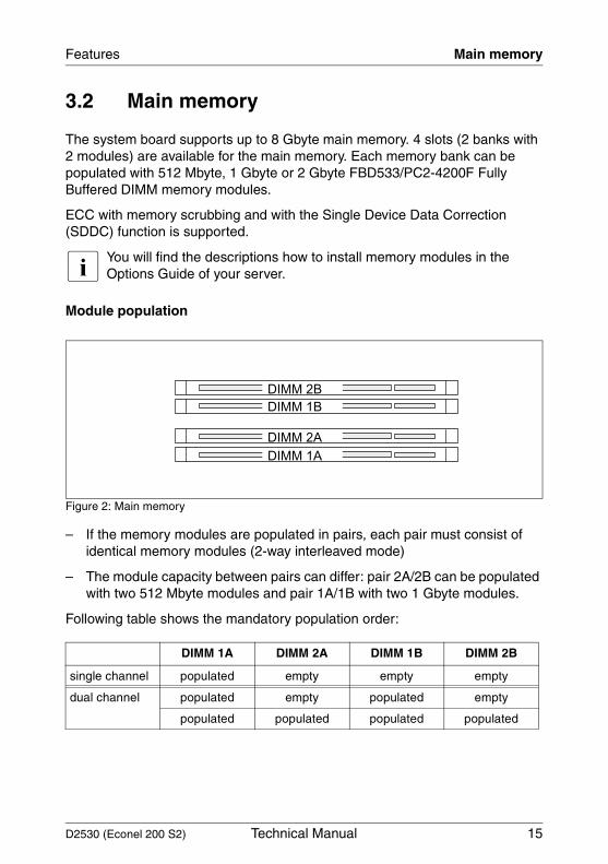
3.2 Main memory
The system board supports up to 8 Gbyte main memory. 4 slots (2 banks with 2 modules) are available for the main memory. Each memory bank can be populated with 512 Mbyte, 1 Gbyte or 2 Gbyte FBD533/PC2-4200F Fully Buffered DIMM memory modules.
ECC with memory scrubbing and with the Single Device Data Correction (SDDC) function is supported.
I You will find the descriptions how to install memory modules in the Options Guide of your server.
Module population
Figure 2: Main memory
– If the memory modules are populated in pairs, each pair must consist of identical memory modules (2-way interleaved mode)
– The module capacity between pairs can differ: pair 2A/2B can be populated with two 512 Mbyte modules and pair 1A/1B with two 1 Gbyte modules.
Following table shows the mandatory population order:
DIMM 1A DIMM 2A DIMM 1B DIMM 2B
single channel populated empty empty empty
dual channel populated empty populated empty
populated populated populated populated
DIMM 2B
DIMM 1B
DIMM 2A
DIMM 1A
16 Technical Manual D2530 (Econel 200 S2)
PCI bus Features
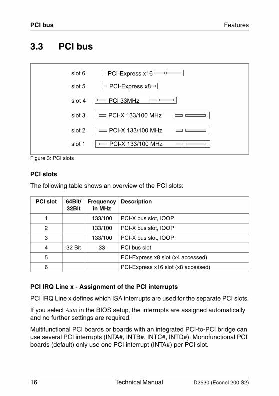
3.3 PCI bus
Figure 3: PCI slots
PCI slots
The following table shows an overview of the PCI slots:
PCI IRQ Line x - Assignment of the PCI interrupts
PCI IRQ Line x defines which ISA interrupts are used for the separate PCI slots.
If you select Auto in the BIOS setup, the interrupts are assigned automatically and no further settings are required.
Multifunctional PCI boards or boards with an integrated PCI-to-PCI bridge can use several PCI interrupts (INTA#, INTB#, INTC#, INTD#). Monofunctional PCI boards (default) only use one PCI interrupt (INTA#) per PCI slot.
PCI slot 64Bit/32Bit
Frequency in MHz
Description
1 133/100 PCI-X bus slot, IOOP
2 133/100 PCI-X bus slot, IOOP
3 133/100 PCI-X bus slot, IOOP
4 32 Bit 33 PCI bus slot
5 PCI-Express x8 slot (x4 accessed)
6 PCI-Express x16 slot (x8 accessed)
slot 6
slot 5
slot 4
slot 3
slot 2
PCI-X 133/100 MHz
PCI-Express x16
PCI-Express x8
PCI 33MHz
PCI-X 133/100 MHz
PCI-X 133/100 MHz
slot 1
D2530 (Econel 200 S2) Technical Manual 17
Features PCI bus
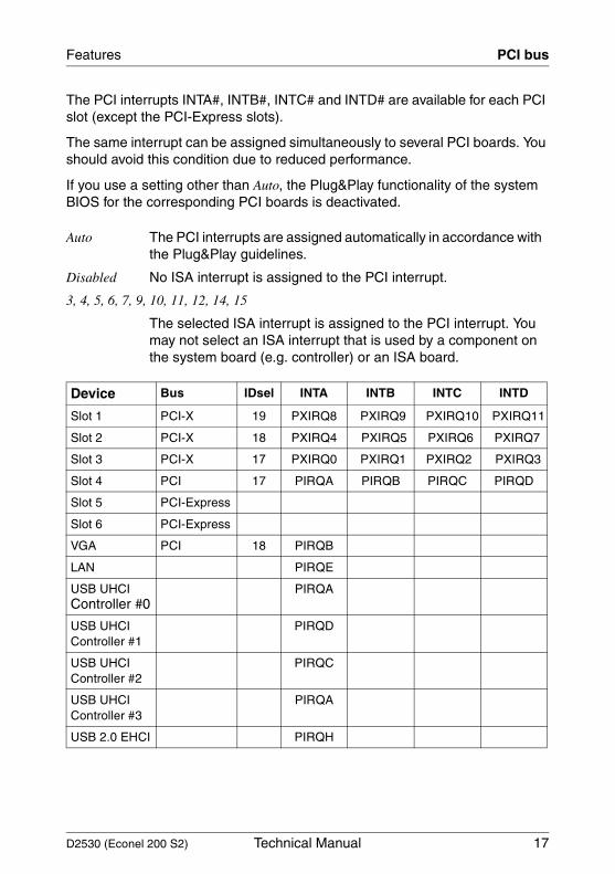
The PCI interrupts INTA#, INTB#, INTC# and INTD# are available for each PCI slot (except the PCI-Express slots).
The same interrupt can be assigned simultaneously to several PCI boards. You should avoid this condition due to reduced performance.
If you use a setting other than Auto, the Plug&Play functionality of the system BIOS for the corresponding PCI boards is deactivated.
Auto The PCI interrupts are assigned automatically in accordance with the Plug&Play guidelines.
Disabled No ISA interrupt is assigned to the PCI interrupt.
3, 4, 5, 6, 7, 9, 10, 11, 12, 14, 15
The selected ISA interrupt is assigned to the PCI interrupt. You may not select an ISA interrupt that is used by a component on the system board (e.g. controller) or an ISA board.
Device Bus IDsel INTA INTB INTC INTD
Slot 1 PCI-X 19 PXIRQ8 PXIRQ9 PXIRQ10 PXIRQ11
Slot 2 PCI-X 18 PXIRQ4 PXIRQ5 PXIRQ6 PXIRQ7
Slot 3 PCI-X 17 PXIRQ0 PXIRQ1 PXIRQ2 PXIRQ3
Slot 4 PCI 17 PIRQA PIRQB PIRQC PIRQD
Slot 5 PCI-Express
Slot 6 PCI-Express
VGA PCI 18 PIRQB
LAN PIRQE
USB UHCIController #0
PIRQA
USB UHCIController #1
PIRQD
USB UHCIController #2
PIRQC
USB UHCIController #3
PIRQA
USB 2.0 EHCI PIRQH
18 Technical Manual D2530 (Econel 200 S2)
Screen resolution Features
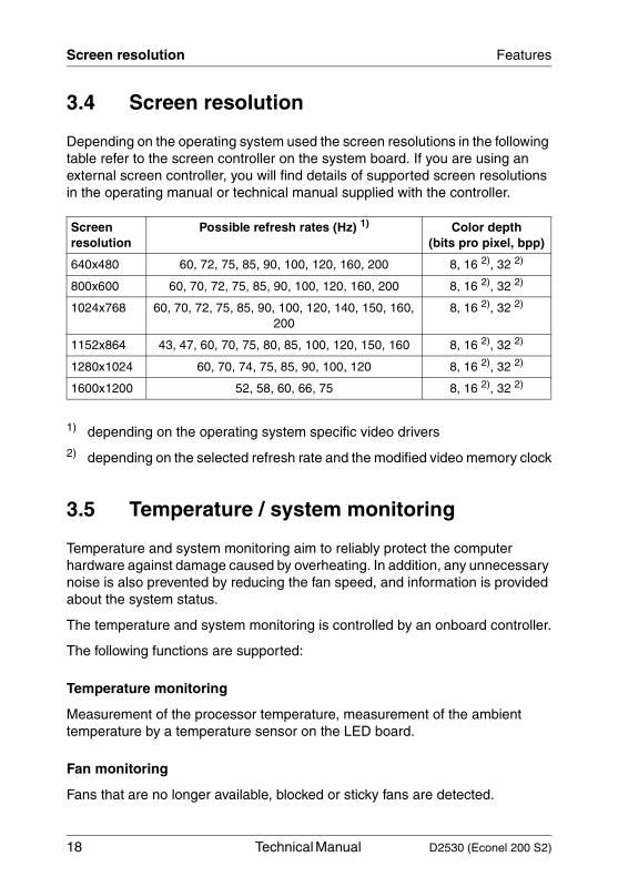
3.4 Screen resolution
Depending on the operating system used the screen resolutions in the following table refer to the screen controller on the system board. If you are using an external screen controller, you will find details of supported screen resolutions in the operating manual or technical manual supplied with the controller.
1) depending on the operating system specific video drivers2) depending on the selected refresh rate and the modified video memory clock
3.5 Temperature / system monitoring
Temperature and system monitoring aim to reliably protect the computer hardware against damage caused by overheating. In addition, any unnecessary noise is also prevented by reducing the fan speed, and information is provided about the system status.
The temperature and system monitoring is controlled by an onboard controller.
The following functions are supported:
Temperature monitoring
Measurement of the processor temperature, measurement of the ambient temperature by a temperature sensor on the LED board.
Fan monitoring
Fans that are no longer available, blocked or sticky fans are detected.
Screen resolution
Possible refresh rates (Hz) 1) Color depth (bits pro pixel, bpp)
640x480 60, 72, 75, 85, 90, 100, 120, 160, 200 8, 16 2), 32 2)
800x600 60, 70, 72, 75, 85, 90, 100, 120, 160, 200 8, 16 2), 32 2)
1024x768 60, 70, 72, 75, 85, 90, 100, 120, 140, 150, 160, 200
8, 16 2), 32 2)
1152x864 43, 47, 60, 70, 75, 80, 85, 100, 120, 150, 160 8, 16 2), 32 2)
1280x1024 60, 70, 74, 75, 85, 90, 100, 120 8, 16 2), 32 2)
1600x1200 52, 58, 60, 66, 75 8, 16 2), 32 2)
D2530 (Econel 200 S2) Technical Manual 19
Features Temperature / system monitoring
Fan control
The fans are controlled according to temperature.
Sensor monitoring
The removal of, or a fault in, a temperature sensor is detected. Should this happen all fans monitored by this sensor run at maximum speed, to achieve the greatest possible protection of the hardware.
Voltage monitoring
The most important voltages are monitored. When a voltage exceeds warning level high or falls below warning level low an alert will be generated. Adequate measurements can be done by running agents.
Cover monitoring
Unauthorised opening of the cover is detected, even when the system is switched off. However, this will only be indicated when the system is switched on again
System Event Log (SEL)
All monitored events of the system board are recorded in the System Event Log. They could be retrieved after a system reboot via ServerView.
20 Technical Manual D2530 (Econel 200 S2)
Connectors and jumpers Features
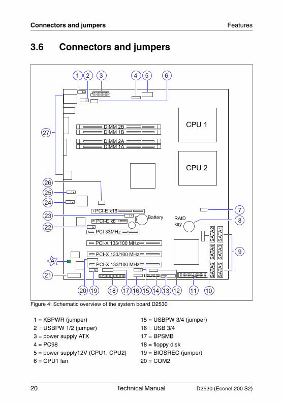
3.6 Connectors and jumpers
Figure 4: Schematic overview of the system board D2530
1 = KBPWR (jumper) 15 = USBPW 3/4 (jumper)
2 = USBPW 1/2 (jumper) 16 = USB 3/4 3 = power supply ATX 17 = BPSMB
4 = PC98 18 = floppy disk
5 = power supply12V (CPU1, CPU2) 19 = BIOSREC (jumper) 6 = CPU1 fan 20 = COM2
3
CPU 1
CPU 2
7
27
14
1 2 4 5 6
DIMM 2BDIMM 1B
DIMM 2ADIMM 1A
9
SA
TA
1S
ATA
3S
ATA
5
SA
TA
2S
ATA
4S
ATA
6
8Battery
11121516171819
21
20
22
23
26
24
25
PCI-X 133/100 MHz
PCI-E x16
PCI-E x8
PCI 33MHz
PCI-X 133/100 MHz
PCI-X 133/100 MHz
RAID
key
13 10
A
D2530 (Econel 200 S2) Technical Manual 21
Features Connectors and jumpers
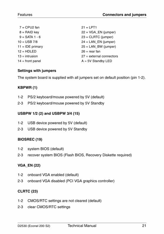
Settings with jumpers
The system board is supplied with all jumpers set on default position (pin 1-2).
KBPWR (1)
USBPW 1/2 (2) and USBPW 3/4 (15)
BIOSREC (19)
VGA_EN (22)
CLRTC (23)
7 = CPU2 fan 21 = LPT1 8 = RAID key 22 = VGA_EN (jumper)
9 = SATA 1 - 6 23 = CLRTC (jumper)
10 = USB 7/8 24 = LAN_EN (jumper)11 = IDE primary 25 = LAN_BW (jumper)
12 = HDLED 26 = rear fan
13 = intrusion 27 = external connectors14 = front panel A = 5V Standby LED
1-2 PS/2 keyboard/mouse powered by 5V (default)
2-3 PS/2 keyboard/mouse powered by 5V Standby
1-2 USB device powered by 5V (default)
2-3 USB device powered by 5V Standby
1-2 system BIOS (default)
2-3 recover system BIOS (Flash BIOS, Recovery Diskette required)
1-2 onboard VGA enabled (default)
2-3 onboard VGA disabled (PCI VGA graphics controller)
1-2 CMOS/RTC settings are not cleared (default)
2-3 clear CMOS/RTC settings
22 Technical Manual D2530 (Econel 200 S2)
Connectors and jumpers Features
LAN_EN (24)
LAN_BW (25)
LED
5V Standby(A)
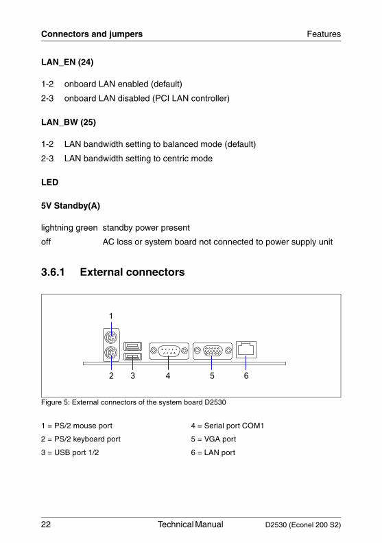
3.6.1 External connectors
Figure 5: External connectors of the system board D2530
1-2 onboard LAN enabled (default)
2-3 onboard LAN disabled (PCI LAN controller)
1-2 LAN bandwidth setting to balanced mode (default)
2-3 LAN bandwidth setting to centric mode
lightning green standby power present
off AC loss or system board not connected to power supply unit
1 = PS/2 mouse port 4 = Serial port COM1
2 = PS/2 keyboard port 5 = VGA port
3 = USB port 1/2 6 = LAN port
3 5 62
1
4
D2530 (Econel 200 S2) Technical Manual 23
Features Connectors and jumpers
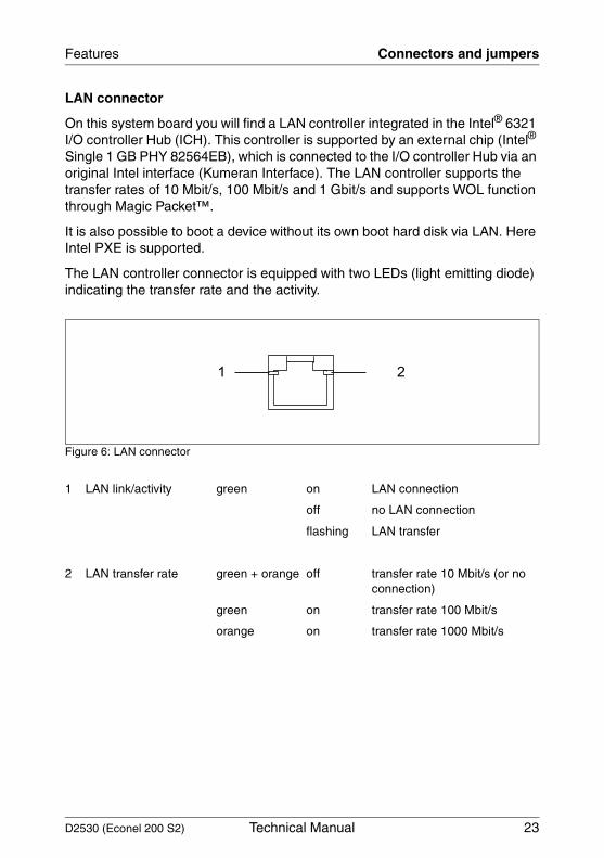
LAN connector
On this system board you will find a LAN controller integrated in the Intel® 6321 I/O controller Hub (ICH). This controller is supported by an external chip (Intel® Single 1 GB PHY 82564EB), which is connected to the I/O controller Hub via an original Intel interface (Kumeran Interface). The LAN controller supports the transfer rates of 10 Mbit/s, 100 Mbit/s and 1 Gbit/s and supports WOL function through Magic Packet™.
It is also possible to boot a device without its own boot hard disk via LAN. Here Intel PXE is supported.
The LAN controller connector is equipped with two LEDs (light emitting diode) indicating the transfer rate and the activity.
Figure 6: LAN connector
1 LAN link/activity green on LAN connection
off no LAN connection
flashing LAN transfer
2 LAN transfer rate green + orange off transfer rate 10 Mbit/s (or no connection)
green on transfer rate 100 Mbit/s
orange on transfer rate 1000 Mbit/s
1 2

D2530 (Econel 200 S2) Technical Manual 25
4 Replacing the lithium batteryIn order to save the system information permanently, a lithium battery is installed to provide the CMOS-memory with a current. When the charge is too low or the battery is empty, a corresponding error message is provided. The lithium battery must then be replaced.
V The lithium battery must be replaced with an identical battery or a battery type recommended by the manufacturer (CR2032).
Do not throw lithium batteries into the trashcan. It must be disposed of in accordance with local regulations concerning special waste.
Make sure that you insert the battery the right way round. The plus pole must be on the top!
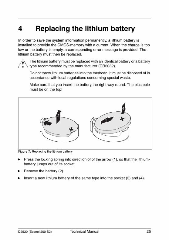
Figure 7: Replacing the lithium battery
Ê Press the locking spring into direction of of the arrow (1), so that the lithium- battery jumps out of its socket.
Ê Remove the battery (2).
Ê Insert a new lithium battery of the same type into the socket (3) and (4).
1
2
3
4

D2530 (Econel 200 S2) Technical Manual 27
AbbreviationsThe technical terms and abbreviations given below represent only a selection of the full list of common technical terms and abbreviations.
Not all technical terms and abbreviations listed here are valid for the described system board.
ACAlternating Current
ACPIAdvanced Configuration and Power management Interface
ANSIAmerican National Standards Institute
ASR&RAutomatic Server Recovery and Restart
ATAAdvanced Technology Attachment
BBUBattery Backup Unit
BIOSBasic Input Output System
BMCBaseboard Management Controller
CMOSComplementary Metal Oxide Semiconductor
COMCOMmunication port
CPUCentral Processing Unit
28 Technical Manual D2530 (Econel 200 S2)
Abbreviations
DDRDouble Data Rate
DIMMDual In-line Memory Module
DIPDual In-line Package
DMIDesktop Management Interface
DRAMDynamic Random Access Memory
ECCError Correction Code
EEPROMElectrical Erasable Programmable Read Only Memory
EFIExtensible Firmware Interface
EGBElektrostatisch gefährdete Bauteile
EHCIEnhanced Host Controller Interface
EMIElectromagnetic interference
EMRLEmbedded RAID Logic
EMVElektromagnetische Verträglichkeit (electromagnetic compatibility)
EPROMErasable Programmable Read Only Memory
D2530 (Econel 200 S2) Technical Manual 29
Abbreviations
ESDElectroStatic Discharge (elektrostatische Entladung)
EVRDEnterprise VRD
HPCHotplug Controller
FPCFront Panel Controller
FRUField Replaceable Unit
FSBFront Side Bus
ICEIn Circuit Emulation
IDEIntegrated (intelligent) Drive Electronics
IECInternational Electrotechnical Commission
IMEIntegrated Mirroring Enhanced
IOOPIntelligent Organisation Of PCI
IPMBIntelligent Platform Management Bus
IPMIIntelligent Platform Management Interface
iRMCintegrated Remote Management Controller
30 Technical Manual D2530 (Econel 200 S2)
Abbreviations
ISOInternational Organisation for Standardisation
LANLocal Area Network
LEDLight Emitting Diode
MPSMulti Processor Specification
NMINon Maskable Interrupt
OEMOriginal Equipment Manufacturer
OHCIOpen Host Controller Interface
OSOperating System
PCIPeripheral Components Interconnect
PDAPrefailure Detection and Analyzing
PIOProgrammed Input Output
PDBPower Distribution Board
PLDProgrammable Logic Device
PS(U)Power Supply (Unit)
D2530 (Econel 200 S2) Technical Manual 31
Abbreviations
PWMPulse Wide Modulation
PXEPreboot eXecution Environment
RAIDRedundant Array of Inexpensive Disks
RoHSRestriction of the Use of Certain Hazardous Substances (Waste from Electric and Electronic Equipment, EU Directive)
RoMBRAID on Motherboard
RSBRemote Service Board
RSTReSeT
RTCReal Time Clock
SASSerial Attached SCSI
SATASerial ATA
SCSISmall Computer Systems Interface
SDDCSingle Device Data Correction
SDRAMSynchronous Dynamic Random Access Memory
SELSystem Event Log
32 Technical Manual D2530 (Econel 200 S2)
Abbreviations
SHDGServer Hardware Design Guide
SMBSystem Management Bus
SMMServer Management Mode
SMPSymmetrical Multi Processing
UHCIUnified Host Controller Interface
USBUniversal Serial Bus
VGAVideo Graphics Adapter
VRDVoltage Regulator Down
VRMVoltage Regulator Module
WEEEWaste from Electric and Electronic Equipment (EU Directive)
WfMWired for Management
WOLWake up On LAN
Comments on System Board D2530for Econel 200 S2
D2530 (Econel 200 S2)
CommentsSuggestionsCorrections
✁
Submitted by
Fujitsu Siemens Computers GmbHUser Documentation81730 MünchenGermany
Fax: (++49) 700 / 372 00000
e-mail: [email protected]://manuals.fujitsu-siemens.com

Information on this document On April 1, 2009, Fujitsu became the sole owner of Fujitsu Siemens Compu-ters. This new subsidiary of Fujitsu has been renamed Fujitsu Technology So-lutions.
This document from the document archive refers to a product version which was released a considerable time ago or which is no longer marketed.
Please note that all company references and copyrights in this document have been legally transferred to Fujitsu Technology Solutions.
Contact and support addresses will now be offered by Fujitsu Technology So-lutions and have the format …@ts.fujitsu.com.
The Internet pages of Fujitsu Technology Solutions are available at http://ts.fujitsu.com/... and the user documentation at http://manuals.ts.fujitsu.com.
Copyright Fujitsu Technology Solutions, 2009
Hinweise zum vorliegenden Dokument Zum 1. April 2009 ist Fujitsu Siemens Computers in den alleinigen Besitz von Fujitsu übergegangen. Diese neue Tochtergesellschaft von Fujitsu trägt seit-dem den Namen Fujitsu Technology Solutions.
Das vorliegende Dokument aus dem Dokumentenarchiv bezieht sich auf eine bereits vor längerer Zeit freigegebene oder nicht mehr im Vertrieb befindliche Produktversion.
Bitte beachten Sie, dass alle Firmenbezüge und Copyrights im vorliegenden Dokument rechtlich auf Fujitsu Technology Solutions übergegangen sind.
Kontakt- und Supportadressen werden nun von Fujitsu Technology Solutions angeboten und haben die Form …@ts.fujitsu.com.
Die Internetseiten von Fujitsu Technology Solutions finden Sie unter http://de.ts.fujitsu.com/..., und unter http://manuals.ts.fujitsu.com finden Sie die Benutzerdokumentation.
Copyright Fujitsu Technology Solutions, 2009