Embed Size (px)
Citation preview


Minutes of the 51st PCSC Meeting held on 25-02-2016 Page 1
SOUTHERN REGIONAL POWER COMMITTEE BENGALURU
Minutes of the 51st Meeting of Protection Coordination Sub-Committee
(PCSC – 51) of SRPC held on 25.02.2016
1. Introduction The 51st meeting of Protection Coordination Sub-Committee (PCSC-51) was held on 25th February, 2016 in the Conference Hall of Southern Regional Power Committee (SRPC), Bangalore. The list of participants is enclosed at Annexure-I.
Sh. S.R. Bhat, Member Secretary (MS), SRPC welcomed the Members and Participants to the meeting and briefed them on the following:
Informed members that Protection Audit Review of Stations (15 in number) under Task-2 by the Consultant was under progress. Audit of 10 Stations has already been completed. The remaining five Stations, viz., 220 kV Kothagudem TPS (14-16 March, 2016), 220 kV Kaiga APS (4-6 April, 2016), 400/ 220 kV Guttur SS, 400/220 kV Raichur TPS, and 220 kV Nagjheri Station, would also be audited shortly. He requested Constituents’ active cooperation in completing Task-2 activities to the satisfaction of all parties involved.
Reminded members of completion of dead-lines of time-extensions given to various SR-Constituents by Hon’ble CERC for completion of their respective Protection Audit Remarks (PAR), and requested them to approach the Commission for obtaining further time-extension. The PAR-Timelines of various SR-Constituents are given at Annexure-II.
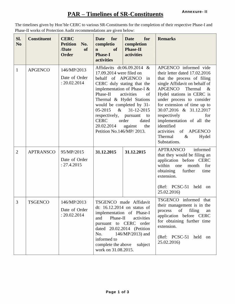
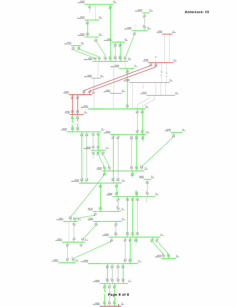
Informed members of the joint study that was conducted on 03.02.2016 with KSEB, SRPC & SRLDC for designing SPS of N-1 & N-2 of 400kV Udumalpet- Palakkad D/C. The minutes of the study are enclosed at Annexure-III.
Apprised members of the special meeting held on 23.02.2016 to discuss the scheduling request of CEPL. The record notes of the meeting are enclosed at Annexure-IV.
22. Confirmation of the Minutes of the 50th PCSC meeting held on 27.01.2016
SE (Protection), SRPC stated that the Minutes of the 50th meeting of the PCSC had been circulated vide SRPC letter No. SRPC/SE-III/ PCSC-49/ 2015/ 1016-48 dated 11.02.2016. As no observations had been received from any of the Constituents, the Minutes of the 50th meeting of PCSC were confirmed.
3. Details of Grid Disturbances (GD’s), Grid Incidents (GI’s), Line Trippings due to Auto-Reclose non-operation and PLCC mal- operation.
The trippings due to GD’s, GI’s, Auto-Reclosure failure/ non-operation, and PLCC mal-operation
that had occurred during the period December, 2015 - January, 2016 were discussed in the Meeting. The deliberations and recommendations of the PCSC-forum are enclosed at Annexure–V.

Minutes of the 51st PCSC Meeting held on 25-02-2016 Page 2
4. Status of pending PCSC recommendations The status of implementation of pending PCSC recommendations was discussed in the meeting.
The Constituents had been requested to kindly submit the status of their compliance latest by 25-03-2016. The updated status of the same as on 15-03-2016 is enclosed at Annexure–VI.
5. Remedial measures/ Action taken for the tripping incidents of the transmission elements
under forced outage The tripping incidents of the transmission elements under forced outage for which the remedial
measures/ actions taken still awaited were discussed in the meeting. The Constituents had been requested to kindly furnish the remedial measures/ action taken in time so as to forward the same to Central Electricity Authority. The updated list of the same as on 15.03.2016 is enclosed at Annexure-VII.
6. Certificate for Healthiness of Batteries
As per the MoP/ CEA direction given in pursuant to recommendations of the Enquiry Committee (NEW grid disturbance on 30th & 31st July, 2012), RPC’s are required to obtain from their respective Constituents the monthly certificate for healthiness of batteries, installed at 220 KV and above voltage level Substations (for power supply to Relays, RTUs and PLCC equipment) and furnish the same to CEA/ MoP. With reference to above, the Constituents have been requested to submit the certificate on healthiness of batteries on monthly basis (i.e. status for a month may be sent by the 7th day of the following month) to SRPC. The sought status for the month of January, 2015 has not been received from the following SR-Constituents:
APTRANSCO, PED, CEPL, TPCIL
7. Review of Islanding Schemes for Southern Region With the addition of new generators & transmission elements in the Southern Region (SR), the
existing islanding schemes of SR have been reviewed, and the modified Islands incorporating these new elements as enclosed at Annexure-VIII were discussed in the meeting.
It was highlighted that as per the current scenario (January, 2016), Load Generation Balance of
Hyderabad and Chennai Islands had not been achieved. In this regard, the Constituents were requested to kindly furnish the details of (i) load relief from df/dt and AUFR relays, (ii) participating generators, and (iii) participating loads to be considered in various Islanding Schemes latest by 25.03.2016 so as to finalize the revised Islanding Schemes in the next PCSC meeting.
8. Load Impedance Encroachment and Over current protection settings.
The issue of model settings to be adopted for Load Impedance Encroachment and Over Current Protection were discussed in the meeting. A presentation showing the guidelines given by the

Minutes of the 51st PCSC Meeting held on 25-02-2016 Page 3
Ramakrishna Committee in this regard is enclosed at Annexure-IX. The IEEE document on “Transmission line Protective Systems loadability” is also enclosed at Annexure-X for kind reference.
All Constituents are requested to ensure Load Impedance Encroachment and Over current
protection settings of their respective systems are generally in line with the above guidelines. 9. Review of implementation of certain Protection Audit Recommendations (PAR) of SR
Constituents In the meeting, change in scope of certain PAR of SR-Constituents had been discussed. The
responsibility of complying with those PAR was discussed and fixed as given at Annexure-XI. 10. Status report on implementation of protection audit recommendations by SR-Constituents In compliance of CERC Order dated 18.08.2015 w.r.t Petition Nos. 86/MP/2014 and
374/MP/2014, SRPC had been directed to submit a bi-annual report regarding implementation of protection audit recommendations by SR-Constituents. In this regard, based on the updates received from SR-Constituents, a status report has been submitted to Hon’ble CERC vide SRPC letter no: SRPC/ PAR/ SE-III/ 2015/ 1375-76 dated 02.03.2016. A copy of the same is enclosed at Annexure-XII for ready reference.
11. Network configuration changes
As per the information furnished by SR-Constituents to the OCC forum in their 116th meeting
(held on 10.02.2015; Minutes circulated on 26.02.2016), the following network configuration changes (additions/ deletions/ modifications of transmission elements) took place in the southern grid during the period December, 2015 - February, 2016.
Hinduja NPCL Unit-1 (520 MW) in AP declared on COD from 11.01.2016. Coastal Energen Unit II (600 MW) declared COD from 0000 hrs of 15.01.2016. 220KV LILO from 220KV Kalkiri – Chinkampalli line to 220KV Thimmapuram SS in Chittoor
District of Ckt km 2.228 was Commissioned on 16.12.2015 by APTRANSCO. 220/132/33kV LIS Substation Thimmapuram of capacity (MVA) 131.5 was commissioned
on 16.12.2015. Consequent to the successful Trial Operation, following assets under “Transmission
System associated with Phase-I, Generation Projects in Odisha, Part-A, Eastern Region” have been put under Commercial Operation w.e.f 0.00 Hrs of 27.01.2016 in terms of clause 4 of CERC (Terms and Conditions of Tariff) Regulations, 2014.
765 KV S/C Angul – Jharsuguda (Sundargarh) line –I along with 765KV Bays i.e. 709L & 709R at Angul pooling Station and 710,711,& 712 at Sundargarh Pooling Station, and 1 no 3x80MVAR Switchable Line Reactor at Angul Pooling Station and associated Bays, under Phase –I, Generation Projects in Odisha, part –A, in Eastern Region.
Consequent to the successful Trial Operation, following assets under “Transmission System associated with Phase-I, Generation Projects in Odisha, Part-A, Eastern Region” have been put under Commercial Operation w.e.f 0.00 Hrs of 25.01.2016 in terms of
Minutes of the 51st PCSC Meeting held on 25-02-2016 Page 4
clause 4 of CERC (Terms and Conditions of Tariff) Regulations, 2014. One set of 765/400 kV, 3x500 MVA Transformer ICT III at Angul Pooling Station and
associated bays(710T, 710,711,413 T,413 & 414) under Transmission System associated with Phase-I, Generation Projects in Odisha, Part-A, Eastern Region”
Narasaraopet 220KV SS in Guttur District of 2x100 MVA Capacity was augmented to 3x100 MVA capacity and was commissioned on 01.01.2016 by APTRANSCO.
220kV LILO line from RSS – Warangal DC line to 220kV /132 SS Manthani of Ckt Km 59 was commissioned on 06.01.2016 by TSTRANSCO.
1x100 MVA Transformer of Manthani 220/132kV SS (2x100 MVA Capacity) in Karimnagar District was commissioned on 06.02.2016 by TSTRANSCO.
KKNPP Unit I which was under outage for Annual Maintenance Work from 11:30 hrs of 24.06.2015 was revived at 07:12 hrs of 30th January 2016.
12. Instances of SPS Operation
Based on the information furnished by SRLDC, it is informed that the following instances of SPS operation took place in SR during the period 27.01.2016 – 24.02.2016.
Sl No
Date Time (hrs)
Reason Load relief obtained (MW)
AP KAR KEL TN Total
1 28-Jan-16 19:52 SPS S3-800 operated 150 84 150 253 637
2 09-Feb-16 7:59 Wardha-Parli SPS operated due
to tripping of Aurangabad-Sholapur line
230 155 120 170 675
3 09-Feb-16 8:34 Wardha-Parli SPS operated 230 140 80 156 606
4 20-Feb-16 18:22 Talcher-Kolar SPS operated as
pole-1 tripped 0 500 0 592 1092
5 21-Feb-16 16:46 Talcher-Kolar SPS operated as
pole-1 tripped 300 450 0 334 1084
6 22-Feb-16 12:25 Suspected Overdrawl by SR
constituents 138 100 0 92 330
13. Compliance of Hon’ble CERC Orders
13.1 Petition No. 146/MP/2013 with I.A. 36/2013: Order dated 20.02.2014
Compliance of Regulations 5.2 I of the Grid Code: Issue regarding non-furnishing of FIR / Trip Analysis Report, EL, DR, etc. was also highlighted. It is pointed out that the above reports are to be submitted / uploaded on SRLDC web application within 24 hours as mandated under IEGC / CEA Regulations.

Minutes of the 51st PCSC Meeting held on 25-02-2016 Page 5
Implementation of Phase-I and Phase-II of Protection Audit Recommendations: All the constituents are requested to submit the updated status of the compliance (those who have not completed recommendations mentioned in the Phase I and Phase II) to SRPC Secretariat at the earliest.
Compliance of Regulations 5.2 (e) & 5.2 (l) of the Grid Code and Regulation 3(1)(e) of CEA Grid Standards: The constituents are requested to strictly comply with these provisions by ensuring standard protections systems having the reliability, selectivity, speed and sensitivity to isolate the faulty equipment and protect all components from any type of faults, within the specified fault clearance time and providing protection coordination
Ensuring proper maintenance of transmission lines and adopting best O&M practices: The constituents are requested to conduct line patrolling regularly as per the SRPC transmission line patrolling guidelines (available under the menu item “All Uploads Operation Miscellaneous Transmission Line Patrolling Protocol / Guidelines for Southern Region” on SRPC website). (http://www.srpc.kar.nic.in/website/2014/operation/patrolling.pdf).
13.2 Petition No. 167/Suo- Motu/2012: Order dated 22.02.2014
The Constituents are requested to follow approved protection philosophy
ISTS licensees are requested to submit details of updated distance protection relay setting of all inter-regional lines to POSOCO & RPCs.
All SLDCs are requested to install/activate sound recording system in their control rooms within three months from the date of issue of this order.
The Constituents are requested to submit the progress of implementation to SRPC and SRLDC as specified in the Hon’ble CERC Order.
13.3 Petition No. 263/MP/2012: Order dated 19.12.2013
Constituents are requested to implement the quantum of relief by AUFR and df/dt relays by identifying additional feeders and keep them functional within one month of issuing this order.
SLDCs are also requested to map these relays on their respective SCADA system within three months of issuance of this order.
The Constituents are requested to submit the progress of implementation to SRPC and SRLDC as specified in the Hon’ble CERC Order.
13.4 APTRANSCO’s Petition No.95/MP/2015: Date of hearing 09-04-2015
It was noted in the Analysis and Decision part of the Order that:
“8. Noting the submissions of the petitioner, SRPC and SRLDC and activities initiated by the petitioner for procurement of materials required for implementation of the remarks of protecting audit, we allow time to the petitioner till 31.12.2015 for completion of our directions in Order dated 19.12.2013 in Petition No. 146/MP/2013.”
“9. SRPC is directed to monitor the status of completion of works relating to protection

Minutes of the 51st PCSC Meeting held on 25-02-2016 Page 6
audit remarks in respect of 7 nos 400 kV sub-stations and 11 nos 220 kV sub-stations of APTRANSCO, protection audit remarks in Protection Coordination Sub-Committee (PCSC) meetings and coordinate the periodic protection audit to be carried out in Southern Region after deliberation in SRPC and submit bi-monthly report to the Commission.”
13.5 TSTRANSCO’s Petition No.83/MP/2015: Order dated 14-05-2015
It was noted in the Order that:
“12. Noting the submission of the petitioner, SRLDC and SRPC and considering the actions already initiated by the petitioner for implementation of works relating to protection audit, we allow time till 31.10.2015 and 31.8.2016 for implementation of Phase-I and Phase -II works respectively. The petitioner is directed to submit affidavit confirming the completion of Phase I of protection audit remarks by 31.10.2015 and Phase-II of protection audit remarks by 31.8.2016.
13. SRPC is directed to monitor the status of completion of remarks in these substations vis-à-vis protection audit remarks in Protection Coordination Sub Committee (PCSC) meetings. SRPC is further directed to coordinate the periodic protection audit to be carried out in Southern Region after deliberation in SRPC.”
13.6 Order in Petition No. 86/MP/2014 and 374/MP/2014: Order dated 18-08-2015
The time-lines given to the various SR-Constituents for completion of Phase-I and Phase-II activities of Protection Audit Recommendations vide above Order are given below:
(A) KSEBL:
18. Noting the submission of KSEBL, SRLDC and SRPC and considering the actions already initiated by KSEBL for implementation of remarks of protection audit, we allow time till 31.12.2015 and 31.3.2016 for implementation of Phase-II works and R&M works at Idduki HEP respectively.
(B) TANTRANSCO:
21. After considering the submissions of TANTRANSCO, SRLDC and SRPC, it is noted that TANTRANSCO`s request for time till 31.5.2015 for implementation of Phase–I activities of providing numerical relays for feeder protection and Auto transformer protection is already over. We allow time till 30.6.2016 for other Phase-I activities such as provision of line VT, 5 core CT, Time synchronizing with GPS, Disturbance recorder & event logger and Phase-II activities. According to SRLDC, total implementation period is 15 to 16 months for items which involve major procurement, design changes with major site modification/civil activities. Accordingly, we allow 16 months time i.e up to 30.11.2016, for Renovation and Modernization of Singarpet, Singaperumalkoil, Salem and Tondiarpet 230 kV sub-stations from the issue of the order.
(C) NLC:
22. NLC has sought time upto 31.12.2014 and 31.3.2015 for completion of Phase-I work of Numerical Relay Retrofitting and for Phase-II works of providing second battery bank of PLCC respectively. It is noted that the completion dates for Phase-I and Phase-II of protection audit remarks as requested by NLC are already over. Therefore, no direction is required in this regard. However, we direct NLC to file a confirmation report regarding completion of protection audit works for Phase-I and Phase-II.

Minutes of the 51st PCSC Meeting held on 25-02-2016 Page 7
(D) KPTCL:
23. …
…
Considering the submission of KPTCL and SRLDC, we allow time to KPTCL time till 15.01.2016 for completion of Phase-I and Phase-II of protection audit remarks. No further extension shall be granted in this regard.
(E) KPCL:
24. …
…
Considering the submission of KPCL and SRLDC, we allow time to KPCL till 31.10.2015 and 31.12.2015 for completion of Phase-I for Phase-II of protection audit remarks respectively. No further extension shall be granted in this regard.
26. We direct SRPC to (a) submit status of protection audit remarks in respect of APGENCO, NTPC (SR), Talcher, Puducherry, PGCIL (SRTS I & II), MAPS and TANGEDCO, (b) monitor the status of completion of remarks of protection audit in respect of all constituents of Southern Region in Protection Coordination Sub-Committee (PCSC) meetings, and (c) to coordinate periodic protection audit to be carried out in Southern Region after deliberation in SRPC. All the constituents of Southern Region are directed to file their status with SRPC on regular basis to facilitate proper monitoring in PCSC meetings. SRPC is directed to submit bi-annually status report to the Commission confirming the completion of Phase-I, Phase-II and R&M works of protection audit remarks of the constituents of Southern Region.
14. Nomenclature for naming various files uploaded in Web based Tripping Monitoring System of
SRLDC Portal
The nomenclature to be followed by the Constituents in naming various files (FIR, DR, EL, TR) corresponding to a tripping incident was brought out in the SRPC letter No. SRPC/ SE-III/ PCSC-45/ 4609 – 649 dated 26.06.2015 and in the minutes of PCSC-45 issued vide SRPC letter No. SRPC/SE-III/ PCSC-45/ 2015/ 5422-455 dated 21.07.2015. As illustrated therein, the format to be followed for the user entered part-name is given below:
Transmission Element File name to be given by the user
Transmission line SSN_DSN_line#_FT
Inter-connecting Transformer SSN_ICT#_FT
Generating Transformer SSN_GT#_FT
Generating Unit SSN_Unit#_FT
Where, SSN = Source Station Name/ From end Station Name/ Sending end Station Name
DSN = Destination Station Name/ To end Station Name/ Receiving end Station Name

Minutes of the 51st PCSC Meeting held on 25-02-2016 Page 8
FT = File Type (FIR/ DR/ EL/ TR)
All SR-Constituents are requested to kindly intimate the above file naming nomenclature to all the concerned and ensure that it is followed at all stations in their control area so that tripping analysis can be done systematically.
15. Date & Venue of the next Meeting
It is informed that the 52nd PCSC meeting will be held on 30.03.2015 (Wednesday) at 10:30 hrs in the Conference Hall of SRPC, Bengaluru.
*****

Annexure-I
Page 1 of 6

Annexure-I
Page 2 of 6

Annexure-I
Page 3 of 6

Annexure-I
Page 4 of 6

Annexure-I
Page 5 of 6

Annexure-I
Page 6 of 6
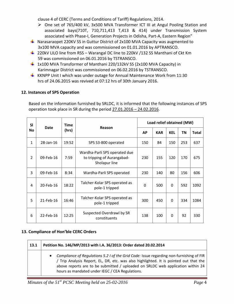
PAR – Timelines of SR-Constituents
The timelines given by Hon’ble CERC to various SR-Constituents for the completion of their respective Phase-I and
Phase-II works of Protection Audit recommendations are given below:
Sl.
No
Constituent CERC
Petition No.
/Date of
Order
Date for
completio
n of
Phase-I
activities
Date for
completion
Phase-II
activities
Remarks
1 APGENCO 146/MP/2013
Date of Order
: 20.02.2014
Affidavits dt:06.09.2014 &
17.09.2014 were filed on
behalf of APGENCO in
CERC duly stating that the
implementation of Phase-l &
Phase-II activities of
Thermal & Hydel Stations
would be completed by 31-
05-2015 & 31-12-2015
respectively, pursuant to
CERC order dated
20.02.2014 against the
Petition No.146/MP/ 2013.
APGENCO informed vide
their letter dated 17.02.2016
that the process of filing
single Affidavit on behalf of
APGENCO Thermal &
Hydel stations in CERC is
under process to consider
for extension of time up to
30.07.2016 & 31.12.2017
respectively for
implementation of all the
identified
activities of APGENCO
Thermal & Hydel
Substations.
2 APTRANSCO 95/MP/2015
Date of Order
: 27.4.2015
31.12.2015 31.12.2015 APTRANSCO informed
that they would be filing an
application before CERC
within one month for
obtaining further time
extension.
(Ref: PCSC-51 held on
25.02.2016)
3 TSGENCO 146/MP/2013
Date of Order
: 20.02.2014
TSGENCO made Affidavit
dt: 16.12.2014 on status of
implementation of Phase-I
and Phase-II activities
pursuant to CERC order
dated 20.02.2014 (Petition
No. 146/MP/2013) and
informed to
complete the above subject
work on 31.08.2015.
TSGENCO informed that
their management is in the
process of filing an
application before CERC
for obtaining further time
extension.
(Ref: PCSC-51 held on
25.02.2016)
Annexure- II
Page 1 of 3

4 TSTRANSCO 83/MP/2015
Date of Order
: 14.5.2015
31.10.2015 31.08.2016 TSTRANSCO informed
that Phase-I activities are
under advanced stage of
completion as Erection &
commissioning of the same
are in progress.
(Ref: PCSC-51 held on
25.02.2016)
5 KPCL 374/MP/2014
Date of Order
: 18.8.2015
31.10.2015 31.12.2015 KPCL informed that they
had filed a Petition (No.
265/MP/2015) dated
29.10.2015 before Hon’ble
CERC praying to grant an
extension of time up to
30.12.2016 for completing
the Phases I and II
activities.
The Commission in its
ROP dated 26.11.2015 for
the Petition No.
265/MP/2015 has directed
the KPCL to file additional
submission, if any, by
22.12.2015.
However, as no additional
submission has been made
by KPCL, order of Hon’ble
CERC for the petition is
awaited.
6 KPTCL 374/MP/2014
Date of Order
: 18.8.2015
15.1.2016 15.1.2016 KPTCL filed a separate
application before CERC on
07.01.2016 seeking time
extension up to 31.05.2017,
and the same is under
consideration by CERC.
7 KSEB 86/MP/2014
Date of Order
: 18.8.2015
31.12.2015
31.12.2015
(excepting
for R&M
works at
Idduki HEP
for which
time
extension is
up to
31.3.2016)
KSEB informed that they
would be filing an
application before CERC
within one month for
obtaining further time
extension up to 31.12.2017.
(Ref: PCSC-51 held on
25.02.2016)
Annexure- II
Page 2 of 3

8 TANTRANSCO 374/MP/2014
Date of Order :
18.8.2015
30.6.2016 30.11.2016
9 NLC 146/MP/2013
Date of Order
: 20.02.2014
374/MP/2014
Date of Order
: 18.8.2015
As per the affidavit
submitted to CERC
regarding completion of
Phase-I & Phase-II audit
works against the CERC
Order dated 20.02.2014 for
the Petition 146/MP/2013,
NLC has sought time up to
31-12-2014 for completion
of Phase-I and up to 31-03-
2015 for completion of
Phase-II activities.
NLC has been directed to file
a confirmation report before
CERC regarding completion
of protection audit works for
Phase-I and Phase-II in
compliance with CERC
Order dated 18.08.2015
against the Petition
374/MP/2014.
NLC informed that their
Phase-I works had been
completed before
31.12.2014. And their
pending Phase-II works (2
no.) had also been
completed by the third week
of February, 2016.
(Ref: PCSC-51 held on
25.02.2016)
10 NPCIL 146/MP/2015
Date of Order
: 20.02.2014
01.05.2014 01.09.2014 As per the status furnished
to SRPC, out of the total 9
recommendations given
covering KAPS and MAPS,
two no. of recommendations
pertaining to MAPS are yet
to be complied with.
Note: PGCIL (SR-I & SR-II) and NTPC (excluding Talcher), and majority of the IPP’s have completed
implementation of their respective Protection Audit Works.
Annexure- II
Page 3 of 3

Annexure- III
Page 1 of 8

Annexure- III
Page 2 of 8

Tnrnelvelr - K6rht doohv OEh EorhmirtlDned, Ttre SPS would he reuieured sfler conrmltsionlnH
of G0 kV Ttrunel,.Ejl-xa+t.llnc which ll under EanstructlorE.
o t,t'ff,iau(5,P lurnrh SftlO[-FoSOCoI i"F
CHIEF ENGINEER FreNC.)System Opcratbn, LD Oenlre&AEBard t5. lbl.nt.lttry
-h- VbIlL.
^1-' qtv
PaB,e I trtl
Annexure- III
Page 3 of 8

452001KANYAMPT
0.9193.3
452034AREACODE-B
0.9199.6
432004KADAKOLA
0.9201.6
116.6
10.5
-113.0
-7.8
452035KNHRD-SPL
0.8184.8
452005AREACODE-A
0.9194.3
452013MADKTARA
0.9208.9
452014MALPRMBA
0.9203.9
452016NALLALAM
0.9194.1
452021SHORNUR
0.9206.2
452023VADAKARA
0.9187.7
94.7
-16.0
-94.1
15.7
94.7
-16.0
-94.1
15.7
143.8
17.9
-140.4
-9.0
94.5
30.3
-93.5
-31.8
133.0
21.4
-132.0
-20.1
99.8
16.5
-98.9
-15.9
452009KANHIROD
0.8182.6
452018PALAKAD
1.0210.5
452025COCHIN2
1.0213.0
452026PALAKD2
1.0210.7
452012LOPERIAR
1.0217.2
-37.3
-7.0
37.5
-2.3
-37.3
-7.0
37.5
-2.3
-39.7
-7.0
40.0
-2.9
65.3
25.1
-64.4
-33.8
65.3
25.1
-64.4
-33.8
-108.5
-0.7
108.6
0.6
-108.5
-0.7
108.6
0.6
-108.5
-0.7
108.6
0.6
105.0
41.0
452002IDUKKI2
1.0220.0
452006BRAHMPRM
1.0212.9
93.1
23.6
-92.6
-25.7
93.1
23.6
-92.6
-25.7
-79.0
-25.3
79.8
21.0
-79.0
-25.3
79.8
21.0
-33.5
-4.8
33.5
4.1
-33.5
-4.8
33.5
4.1
598.0
254.1
452008KLMSSERY
1.0213.1
-70.9
6.0
1
1
71.0
-3.8
-70.9
6.0
1
1
71.0
-3.8
-37.4
8.4
37.4
-10.0
-37.4
8.4
37.4
-10.0
120.3
29.7
-118.5
-29.9
120.3
29.7
-118.5
-29.9
452019PALOM
1.0212.2
452003SABRGRI
1.0216.0
22.6
-2.8
-22.5
-4.7
47.7
-3.8
-47.2
-10.5
110.5
6.5
-109.0
-8.2
1
304.0
106.6
452004EDAMAN2
1.0212.6
39.2
23.9
-39.0
-29.8
40.0
24.5
-39.8
-30.3
40.0
24.5
-39.8
-30.3
22.0
-45.9
-21.6
34.3
1
98.8
28.9
452007EDAPAN
1.0209.7
452011KUNDARA
1.0210.6 452020
POTHNCOD1.0212.3
142.8
18.1
-142.0
-18.2
184.6
19.5
-183.7
-15.8
-21.3
3.8
21.3
-9.7
-21.3
3.8
21.3
-9.7
190.3
8.7
-188.4
-0.4
190.3
8.7
-188.4
-0.4
452017PALMNEW
1.0212.36
9.1
9.4
-69.1
-10.1
184.6
49.8
-181.5
452010KAYMKLM
1.0210.5
-25.4
-1.6
25.4
-4.5
-26.9
-17.2
27.0
11.5
-25.6
25.6
22.1
0.0
0.0
452024TRIVDRM4
1.0212.4
-105.4
-16.0
105.4
13.8
-105.4
-16.0
105.4
13.8
-105.4
-16.0
105.4
13.8
-105.4
-16.0
105.4
13.8
-140.6
-18.4
1
1
141.0
27.0
-140.6
-18.4
1
1
141.0
27.0
-140.6
-18.4
1
1
141.0
27.0
-182.9
0.5
1
1
183.7
14.0
-182.9
0.5
1
1
183.7
14.0
46.7
-93.8
-45.0
91.1
1
0.0
-75.0
-41.1
-25.0
81.7
31.8
-80.3
-36.0
149.8
28.0
-144.2
-11.7
52.6
-20.0
-52.2
14.9
452037KOZHIKODE
0.9199.4
-215.4
-14.4
219.1
29.6
-215.4
-14.4
219.1
29.6
1
0.0
-13.8
454004COCHIN
1.0387.1
454002TRIVNDRM
1.0391.0
454005PALAKD
1.0385.8
444004MYWADI
1.0386.8
454001TRICHUR
1.0385.7
458.6
-30.0
-454.9
25.4
458.6
-30.0
-454.9
25.4
-269.9
7.8
271.2
-39.4
-269.9
7.8
271.2
-39.4
R1
71.0
-57.0
-71.0
3.8
71.0
-57.0
-71.0
3.8
442006THENI2
0.9218.2
442004ABISEK42
1.0225.1
442005UDMLPT2
0.9216.1
1
Annexure- III
Page 4 of 8

452001KANYAMPT
0.9190.8
452034AREACODE-B
0.9197.4
432004KADAKOLA
0.9200.4
121.7
15.5
-117.8
-10.8
452035KNHRD-SPL
0.8181.2
452005AREACODE-A
0.9191.3
452013MADKTARA
0.9206.9
452014MALPRMBA
0.9201.6
452016NALLALAM
0.9191.0
452021SHORNUR
0.9204.0
452023VADAKARA
0.8184.2
100.9
-15.3
-100.315.6
100.9
-15.3
-100.3
15.6
145.6
20.9
-142.0
-10.7
88.7
33.3
-87.8
-35.0
129.9
24.4
-128.9
-23.1
100.2
18.8
-99.3
-17.8
452009KANHIROD
0.8178.7
452018PALAKAD
0.9208.2
452025COCHIN2
1.0212.1
452026PALAKD2
0.9208.4
452012LOPERIAR
1.0216.5
-29.2
-6.8
29.3
-2.7
-29.2
-6.8
29.3
-2.7
-32.0
-6.9
32.2
-3.2
82.3
29.8
-80.9
-35.7
82.3
29.8
-80.9
-35.7
-101.2
-1.7
101.3
1.6
-101.2
-1.7
101.3
1.6
-101.2
-1.7
101.3
1.6
105.0
41.0
452002IDUKKI2
1.0220.0
452006BRAHMPRM
1.0212.0
110.1
31.1
-109.3
-32.0
110.1
31.1
-109.3
-32.0
-78.7
-26.9
79.5
22.8
-78.7
-26.9
79.5
22.8
-10.0
-2.6
10.0
1.9
-10.0
-2.6
10.0
1.9
598.0
298.5
452008KLMSSERY
1.0212.2
-39.4
11.5
1
1
39.5
-10.8
-39.4
11.5
1
1
39.5
-10.8
-29.4
11.7
29.5
-13.4
-29.4
11.7
29.5
-13.4
129.3
34.9
-127.2
-33.6
129.3
34.9
-127.2
-33.6
452019PALOM
1.0212.0
452003SABRGRI
1.0216.0
3.6
-4.2
-3.6
-3.6
63.2
-2.4
-62.3
-9.9
122.8
7.0
-120.9
-7.0
1
304.0
131.2
452004EDAMAN2
1.0212.2
29.2
29.2
-29.0
-35.2
29.8
29.9
-29.6
-35.8
29.8
29.9
-29.6
-35.8
35.1
-49.7
-34.4
39.2
1
98.8
28.9
452007EDAPAN
1.0209.4
452011KUNDARA
1.0210.2 452020
POTHNCOD1.0211.8
154.5
17.5
-153.6
-16.0
195.6
19.1
-194.7
-14.2
-32.1
7.8
32.2
-13.5
-32.1
7.8
32.2
-13.5
206.7
8.1
-204.4
4.3
206.7
8.1
-204.4
4.3
452017PALMNEW
1.0212.07
4.9
11.7
-74.9
-12.5
172.5
54.3
-169.7
452010KAYMKLM
1.0210.2
-36.7
0.5
36.8
-6.3
-14.2
-19.8
14.2
14.1
-15.9
15.9
24.0
0.0
0.0
452024TRIVDRM4
1.0211.9
-111.6
-14.0
111.6
11.8
-111.6
-14.0
111.6
11.8
-111.6
-14.0
111.6
11.8
-111.6
-14.0
111.6
11.8
-148.8
-15.7
1
1
149.3
25.3
-148.8
-15.7
1
1
149.3
25.3
-148.8
-15.7
1
1
149.3
25.3
-168.0
-0.8
1
1
168.6
13.2
-168.0
-0.8
1
1
168.6
13.2
87.7
-102.4
-84.9 10
5.4
1
0.0
-74.5
-47.2
-26.9
81.8
32.4
-80.3
-36.2
151.3
31.9
-145.4
-13.4
57.4
-17.3
-56.8
12.8
452037KOZHIKODE
0.9196.9
-221.0
-17.5
225.0
34.5
-221.0
-17.5
225.0
34.5
1
0.0
-13.2
454004COCHIN
1.0384.1
454002TRIVNDRM
1.0389.8
454005PALAKD
1.0381.5
444004MYWADI
1.0384.9
454001TRICHUR
1.0382.3
801.4
15.1
-789.8
68.8
-225.3
12.8
226.3
-47.6
-225.3
12.8
226.3
-47.6
R1
39.5
-63.5
-39.5
10.8
39.5
-63.5
-39.5
10.8
442006THENI2
0.9217.8
442004ABISEK42
1.0224.6
442005UDMLPT2
0.9215.5
1
Annexure- III
Page 5 of 8

452001KANYAMPT
0.9197.2
452034AREACODE-B
0.9205.1
432004KADAKOLA
0.9203.4
112.4
1.9
-109.2
-1.3
452035KNHRD-SPL
0.9191.2
452005AREACODE-A
0.9199.1
452013MADKTARA
1.0214.1
452014MALPRMBA
1.0209.9
452016NALLALAM
0.9199.2
452021SHORNUR
1.0212.4
452023VADAKARA
0.9193.6
91.2
-20.5
-90.7
19.8
91.2
-20.5
-90.7
19.8
142.3
11.4
-139.2
-4.2
82.8
24.2
-82.1
-27.4
108.6
6.6
-108.0
-7.3
99.3
12.5
-98.5
-12.4
452009KANHIROD
0.9189.2
452018PALAKAD
1.0216.4
452025COCHIN2
1.0214.5
452026PALAKD2
1.0216.4
452012LOPERIAR
1.0218.5
-35.1
-12.8
35.3
2.8
-35.1
-12.8
35.3
2.8
-35.9
-11.5
36.1
0.9
64.5
5.3
-63.7
-15.3
64.5
5.3
-63.7
-15.3
-75.9
13.2
76.0
-13.7
-75.9
13.2
76.0
-13.7
-75.9
13.2
76.0
-13.7
105.0
41.0
452002IDUKKI2
1.0220.0
452006BRAHMPRM
1.0214.3
95.5
2.6
-95.0
-4.7
95.5
2.6
-95.0
-4.7
-82.2
-24.1
83.0
19.9
-82.2
-24.1
83.0
19.9
-20.3
-17.4
20.3
16.6
-20.3
-17.4
20.3
16.6
598.0
185.3
452008KLMSSERY
1.0214.4
-48.9
-16.0
1
1
49.0
17.1
-48.9
-16.0
1
1
49.0
17.1
-28.6
-1.1
28.6
-0.7
-28.6
-1.1
28.6
-0.7
123.2
18.9
-121.3
-19.2
123.2
18.9
-121.3
-19.2
452019PALOM
1.0212.7
452003SABRGRI
1.0216.0
18.2
6.6
-18.2
-14.3
50.5
-10.1
-49.9
-4.1
111.2
3.0
-109.8
-4.7
1
304.0
84.3
452004EDAMAN2
1.0212.8
37.5
22.1
-37.3
-28.1
38.3
22.7
-38.1
-28.6
38.3
22.7
-38.1
-28.6
23.3
-45.0
-22.8
33.4
1
98.8
28.9
452007EDAPAN
1.0210.0
452011KUNDARA
1.0210.8 452020
POTHNCOD1.0212.7
143.9
17.0
-143.1
-17.0
185.5
18.4
-184.6
-14.6
-23.5
2.9
23.6
-8.9
-23.5
2.9
23.6
-8.9
191.5
9.3
-189.6
-0.8
191.5
9.3
-189.6
-0.8
452017PALMNEW
1.0212.77
0.8
4.2
-70.8
-5.0
183.1
45.5
-180.0
452010KAYMKLM
1.0210.8
-26.5
-0.6
26.5
-5.5
-25.3
-18.4
25.4
12.7
-24.6
24.6
23.2
0.0
0.0
452024TRIVDRM4
1.0212.7
-106.7
-16.4
106.7
14.2
-106.7
-16.4
106.7
14.2
-106.7
-16.4
106.7
14.2
-106.7
-16.4
106.7
14.2
-142.2
-18.9
1
1
142.7
27.7
-142.2
-18.9
1
1
142.7
27.7
-142.2
-18.9
1
1
142.7
27.7
-132.0
20.1
1
1
132.4
-12.7
-132.0
20.1
1
1
132.4
-12.7
55.8
-92.3
-54.0
90.0
1
0.0
-76.0
-37.3
-26.0
81.6
30.5
-80.3
-35.7
148.4
20.7
-143.3
-7.3
48.9
-26.2
-48.4
20.6
452037KOZHIKODE
0.9203.3
-212.3
-5.8
215.7
19.2
-212.3
-5.8
215.7
19.2
1
0.0
-14.8
454004COCHIN
1.0393.1
454002TRIVNDRM
1.0391.7
454005PALAKD
1.0391.9
444004MYWADI
1.0388.6
454001TRICHUR
1.0392.8
680.7
-80.1
-672.4
124.9
-203.1
9.9
203.8
-49.7
-203.1
9.9
203.8
-49.7
R1
49.0
-38.4
-49.0
-17.1
49.0
-38.4
-49.0
-17.1
442006THENI2
0.9218.4
442004ABISEK42
1.0225.4
442005UDMLPT2
0.9216.6
1
Annexure- III
Page 6 of 8

452001KANYAMPT
0.9192.3
452034AREACODE-B
1.0209.2
432004KADAKOLA
0.9202.2
114.2
17.5
-110.8
-15.2
452035KNHRD-SPL
0.8181.7
452005AREACODE-A
0.9192.3
452013MADKTARA
1.0217.9
452014MALPRMBA
1.0220.0
452016NALLALAM
0.9191.6
452021SHORNUR
1.0220.0
452023VADAKARA
0.8184.7
88.1
-7.2
-87.6
6.7
88.1
-7.2
-87.6
6.7
143.2
24.0
-139.7
-14.5
99.9
19.1
-99.0
-18.1
452009KANHIROD
0.8179.2
452018PALAKAD
1.0220.0
452025COCHIN2
1.0215.5
452026PALAKD2
1.0220.0
452012LOPERIAR
1.0219.31
02.5
-15.7
-100.7
10.8
102.5
-15.7
-100.7
10.8
105.0
41.0
452002IDUKKI2
1.0220.0
452006BRAHMPRM
1.0215.1
139.8
-16.6
-138.6
17.5
139.8
-16.6
-138.6
17.5
-87.7
-22.5
88.6
18.7
-87.7
-22.5
88.6
18.7
54.8
-43.4
-54.8
42.9
54.8
-43.4
-54.8
42.9
598.0
167.6
452008KLMSSERY
1.0215.1
55.3
-55.4
1
1
-55.2
57.9
55.3
-55.4
1
1
-55.2
57.9
0.5
-14.4
-0.5
12.5
0.5
-14.4
-0.5
12.5
150.8
9.7
-148.1
-5.9
150.8
9.7
-148.1
-5.9
452019PALOM
1.0212.8
452003SABRGRI
1.0216.0
-34.9
23.8
35.1
-30.7
93.4
-18.5
-91.4
11.3
142.9
-2.0
-140.5
5.0
1
304.0
103.7
452004EDAMAN2
1.0212.3
9.9
32.0
-9.8
-38.4
10.1
32.8
-10.0
-39.0
10.1
32.8
-10.0
-39.0
58.1
-52.2
-56.9
44.0
1
98.8
28.9
452007EDAPAN
1.0209.8
452011KUNDARA
1.0210.5 452020
POTHNCOD1.0212.1
174.8
13.6
-173.6
-9.3
214.6
15.3
-213.5
-8.4
-54.3
11.2
54.6
-16.0
-54.3
11.2
54.6
-16.0
234.3
9.5
-231.3
9.9
234.3
9.5
-231.3
9.9
452017PALMNEW
1.0212.88
8.1
-0.9
-88.0
0.1
151.9
48.4
-149.7
452010KAYMKLM
1.0210.8
-56.7
6.8
56.8
-12.1
8.9
-27.4
-8.8
21.7
1.3
-1.3
29.9
0.0
0.0
452024TRIVDRM4
1.0212.1
-124.2
-12.2
124.2
10.0
-124.2
-12.2
124.2
10.0
-124.2
-12.2
124.2
10.0
-124.2
-12.2
124.2
10.0
-165.6
-13.4
1
1
166.2
25.2
-165.6
-13.4
1
1
166.2
25.2
-165.6
-13.4
1
1
166.2
25.2
1
1
1
1
173.3
-105.2
-166.6
126.3
1
0.0
-76.5
-44.4
-32.8
81.6
29.5
-80.3
-35.4
149.3
33.9
-143.6
-16.4
50.4
-12.7
-50.0
7.4
452037KOZHIKODE
0.9198.2
-209.3
-25.5
212.9
40.2
-209.3
-25.5
212.9
40.2
1
0.0
-13.3
454004COCHIN
1.0400.4
454002TRIVNDRM
1.0390.2
454005PALAKD
1.0403.5
444004MYWADI
1.0388.5
454001TRICHUR
1.0401.70
.0
-50.5
0.0
0.0
0.0
-50.5
0.0
0.0
R1
-55.1
0.3
55.2
-57.9
-55.1
0.3
55.2
-57.9
442006THENI2
0.9218.1
442004ABISEK42
1.0224.7
442005UDMLPT2
0.9216.5
1
Annexure- III
Page 7 of 8
452001KANYAMPT
0.9192.6
452034AREACODE-B
1.0211.2
432004KADAKOLA
0.9202.4
114.1
16.9
-110.6
-14.8
452035KNHRD-SPL
0.8182.2
452005AREACODE-A
0.9192.7
452013MADKTARA
1.0219.8
452014MALPRMBA
1.0220.0
452016NALLALAM
0.9192.1
452021SHORNUR
1.0220.0
452023VADAKARA
0.8185.2
88.1
-7.5
-87.6
6.9
88.1
-7.5
-87.6
6.9
143.1
23.5
-139.7
-14.1
99.9
18.7
-99.0
-17.8
452009KANHIROD
0.8179.8
452018PALAKAD
1.0220.0
452025COCHIN2
1.0216.2
452026PALAKD2
1.0220.0
452012LOPERIAR
1.0219.99
2.5
-21.5
-90.9
14.9
92.5
-21.5
-90.9
14.9
105.0
41.0
452002IDUKKI2
1.0220.0
452006BRAHMPRM
1.0215.8
130.7
-24.1
-129.6
24.4
130.7
-24.1
-129.6
24.4
-88.8
-21.4
89.7
17.6
-88.8
-21.4
89.7
17.6
45.7
-46.6
-45.7
46.0
45.7
-46.6
-45.7
46.0
598.0
132.3
452008KLMSSERY
1.0215.7
44.8
-62.3
1
1
-44.6
64.7
44.8
-62.3
1
1
-44.6
64.7
-0.9
-18.1
0.9
16.3
-0.9
-18.1
0.9
16.3
146.4
5.3
-143.8
-2.3
146.4
5.3
-143.8
-2.3
452019PALOM
1.0213.0
452003SABRGRI
1.0216.0
-25.3
25.8
25.5
-32.9
85.2
-20.5
-83.5
11.6
136.1
-2.9
-133.8
4.8
1
304.0
86.8
452004EDAMAN2
1.0212.5
15.2
29.0
-15.1
-35.4
15.5
29.8
-15.4
-36.0
15.5
29.8
-15.4
-36.0
50.8
-50.4
-49.8
41.3
1
98.8
28.9
452007EDAPAN
1.0210.0
452011KUNDARA
1.0210.7 452020
POTHNCOD1.0212.3
168.3
13.5
-167.2
-10.2
208.5
15.1
-207.5
-8.9
-48.6
9.3
48.8
-14.4
-48.6
9.3
48.8
-14.4
225.2
9.4
-222.5
7.5
225.2
9.4
-222.5
7.5
452017PALMNEW
1.0213.08
5.3
-3.1
-85.3
2.4
158.4
45.1
-156.1
452010KAYMKLM
1.0211.0
-50.5
5.9
50.5
-11.4
2.0
-26.3
-2.0
20.4
-4.0
4.0
29.1
0.0
0.0
452024TRIVDRM4
1.0212.4
-120.9
-13.1
120.9
10.9
-120.9
-13.1
120.9
10.9
-120.9
-13.1
120.9
10.9
-120.9
-13.1
120.9
10.9
-161.3
-14.5
1
1
161.8
25.7
-161.3
-14.5
1
1
161.8
25.7
-161.3
-14.5
1
1
161.8
25.7
1
1
1
1
151.5
-103.0
-146.1
118.0
1
0.0
-76.9
-40.4
-32.0
81.5
29.1
-80.3
-35.3
149.3
33.3
-143.6
-16.0
50.3
-13.2
-49.9
7.9
452037KOZHIKODE
0.9198.5
-209.3
-24.8
212.9
39.4
-209.3
-24.8
212.9
39.4
1
0.0
-13.4
454004COCHIN
1.0402.9
454002TRIVNDRM
1.0390.7
454005PALAKD
1.0406.4
444004MYWADI
1.0388.8
454001TRICHUR
1.0404.50
.0
-51.2
0.0
0.0
0.0
-51.2
0.0
0.0
R1
-44.6
6.2
44.6
-64.7
-44.6
6.2
44.6
-64.7
442006THENI2
0.9218.2
442004ABISEK42
1.0225.0
442005UDMLPT2
0.9216.7
1
Annexure- III
Page 8 of 8

Annexure- IV
Page 1 of 10
Record Notes of the Special Meeting on scheduling of Coastal Energen Units I & II Page 1
RECORD NOTES OF THE SPECIAL MEETING HELD ON 23.02.2016 TO DISCUSS
SCHEDULING REQUEST OF COASTAL ENERGEN UNITS I & II.
A Special Meeting on the subject was conducted on 23rd
February 2016 in SRPC Conference
Hall, Bengaluru. The list of participants is enclosed at Annexure- I.
Shri S.R.Bhat, Member Secretary (SRPC) welcomed all the participants to the Meeting. As per
the prevailing grid scenario in SR, the power demand had picked up. The grid had been further
affected on account of the unfortunate fire incident in the control room of Sharavathy Generating
Station of KPCL. Sharavathy was a vital hydro station and as learnt it could take quite some time
before it gets restored. In view of this, the endeavor should be to maximize generation in the
Region to meet demand without compromising grid security.
M/s Coastal Energen (CEPL) had requested to schedule generation of both units (600 MW each)
in the Tuticorin-Pooling Complex. Earlier in the Meeting held on 11.12.2015 in CEA, it had
been decided to limit total generation quantum of NTPL and CEPL to 1,350 MW keeping in
view rating of bus-bar and isolator at NTPL station. CEPL had been asked to limit generation up
to the margin available after allowing full generation at NTPL.
Subsequently, CEPL had proposed a Special Protection Scheme (SPS) in Tuticorin PS -CEPL-
NTPL Complex for running both Units of CEPL till June, 2016, by which time both CEPL and
PGCIL were likely to complete their respective lines. This issue had been discussed in the 50th
Protection Coordination Sub Committee Meeting held on 27.01.2016 at Trivandrum. In that
Meeting, SRLDC had stated the following:
i. With proposed SPS operation, Generation would get reduced but without
commensurate load shedding. In order to achieve LG balance, demand would be met
through higher power flow on 765 kV Raichur-Sholapur lines, which could trigger
operation of inter-regional SPS.
Annexure- IV
Page 2 of 10

Record Notes of the Special Meeting on scheduling of Coastal Energen Units I & II Page 2
ii. In case of non-operation of SPS, there was a chance that end-equipment at NTPL
switchyard would get damaged due to the limitation imposed by its bus-bar rating.
TANTRANSCO had opined that since loads were yet to be identified for the proposed SPS, the
issue be discussed in detail in the forthcoming Meeting of OCC.
In this regard, it was proposed to have three level protection in the event of tripping of 400 kV
Quad Moose D/C CEPL – Tuticorin Pooling Station line.
Scenario of likely power flow that could happen across the Coastal- NTPL Pooling Station
Complex is shown below:
1. With one Unit Operation at CEPL:
Annexure- IV
Page 3 of 10

Record Notes of the Special Meeting on scheduling of Coastal Energen Units I & II Page 3
AND
OR
AND
OR
2. With two Unit Operation at CEPL:
A. Primary protection scheme to be implemented in the Main-1 and Main-2 protection relay of
the 400 kV CEPL- Tuticorin line is shown below:
I. Main – 1:
II. Main - 2:
Annexure- IV
Page 4 of 10

Record Notes of the Special Meeting on scheduling of Coastal Energen Units I & II Page 4
AND
OR
Logic to be implemented is whenever said feeder goes for a 3 phase tripping OR the
power flow on 400 kV CEPL- Tuticorin Pooling Station is less than 15 MW AND both
units are in service; it will trip Unit-2 and bring down Unit-1 generation to 450 MW. The
output contact is taken from the Distance Protection relay and logic is assigned inside the
DCS, such that output will be initiated, in case of 3 phase tripping only. Main I and II
protection relay will have the configuration as said above and hence the chances of
failure are remote. The tripping output is also taken separately from both the relays and
wired up separately for turbine tripping.
B. The secondary protection (as a backup) for the SPS Scheme is given below:
I. Backup -1: The line breaker contacts of 400kV CEPL- Tuticorin line are also wired
up to DCS to execute the scheme as shown below:
Backup – 1:
II. Backup-2: In order to restrict the power flow of 450 MW from CEPL station to NTPL
station, Directional over current relay of 400kV CEPL- NTPL line will also be
configured to protect NTPL system. Setting of the Over current relay is 650 A with
definite time delay of 1.2 sec.
Annexure- IV
Page 5 of 10

Record Notes of the Special Meeting on scheduling of Coastal Energen Units I & II Page 5
Backup – 2:
III. Backup – 3: The Third level of backup protection is envisaged at 400 kV NTPL SS. It
is proposed to have over-current protection on 400 kV NTPL – Tuticorin PS , if the
line current is greater than 2,200 A, then it would trip the 400kV NTPL – Coastal
Energen S/C.
Backup – 3:
Deliberations:
TANTRANSCO:
In order to envisage SPS Scheme with Load shedding, it is difficult to provide
required load specifically for this scheme since numbers of loads had already been
identified for various schemes. Besides, that area had strong renewable injection
which was also to be absorbed.
SRPC:
According to the Backup- 2 SPS scheme, when the line current of 400kV CEPL-
NTPL line is greater than 650 A, one unit would trip while other unit would need to
ramp down to 450 MW within 1.2 sec (as ramping down may take time this could
Annexure- IV
Page 6 of 10

Record Notes of the Special Meeting on scheduling of Coastal Energen Units I & II Page 6
lead to triggering of Backup-3). This could lead to complete station blackout at
Coastal Energen. Thus it would get reflected on flows on Raichur-Sholapur link and
possibly trigger SPS. Since thermal unit takes time to ramp down, as a precautionary
measure maintain one of the Unit at 450 MW and other unit at 550 MW.
NTPL:
NTPL expressed concern regarding the security of bus bar in the event of failure of
SPS operation. They stated that they should be adequately compensated by CEPL in
case any equipment damage occurred at NTPL station on account of non-operation of
SPS and also for any incidental damages. NTPL agreed for Backup-3 SPS. It was
also stated that there should not be any Deviation liability and DC should be protected
during any mal operation of SPS and subsequent complete loss of evacuation.
SRLDC:
SRLDC stated that insulation from deviation liability and DC protection during
maloperation of SPS was not acceptable. SRLDC also pointed out that in case of non
operation of SPS, there could be a loss of both stations (NTPL&CEPL) totaling about
2000MW. This would cause major problems on inter regional Corridor's. Hence the
reliability of operation of SPS should be ensured.
CEPL:
Dedicated line CEPL-Tuticorin PS would come up by June 2016. Tower erection
would start by first week of March 2016. Regarding equivalent load shedding, it
stated that the same was at par with any other generating in SR. Thus, tripping of any
unit would have similar impact on Inter Regional corridor.
Conclusions:
It was decided to proceed with implementation of SPS at CEPL & NTPL.
Total schedule of 450 + 550 MW could be allowed for CEPL. This is subject
to SRLDC approval, keeping in view grid conditions. Unit to be saved should
be maintained at 450 MW ex-bus generation.
Annexure- IV
Page 7 of 10

Record Notes of the Special Meeting on scheduling of Coastal Energen Units I & II Page 7
Compliance report of SPS implemented with inbuilt logic to be furnished to
SRLDC/SRPC.
SRLDC informed that CEPL has to conduct the mock test on SPS and submit
report to them.
Special Protection Scheme implemented at CEPL can be vetted by NTPL
preferably with the help of PGCIL.
CEPL was requested to assist in implementing the SPS at NTPL.
During any prolonged/planned outage at NTPL, NTPL would communicate
the details to SRLDC. Revised set points, if required could be worked out in
consultation with CEPL/NTPL/SRPC. CEPL would not modify the logic by
itself.
Onus would be on CEPL to factor in safety of its equipments before
implementing logic.
SPS can be reviewed/ disabled at any point of time, whenever Grid condition
demand or during non operation of SPS (though logic is getting satisfied)
SPS would be considered as a special case keeping in view the grid condition
(loads picking up & Sharavathy station outage) and would not be cited as
precedence for acceptance of other SPS on similar lines.
***************
Annexure- IV
Page 8 of 10

Annexure- IV
Page 9 of 10

Annexure- IV
Page 10 of 10

Grid Occurrences discussed in 51st PCSC (25-02-2016) 1/ 29
Grid Occurrences - 51
1. Details of Grid Disturbances:
1 Complete outage of 230kV Madurai S/s (Chekanaurani) of TANTRANSCO
(i) Date and Time of Event 19-01-2016 at 11:56 hrs
(ii) Location 230kV Madurai (Chekanaurani) Substation
(iii) Reported Disturbance /
Fault
Fault had occurred in 230kV Madurai-Sembatty line. Trip from
distance relay was not extended to breaker due to protection DC
fail. LBB protection got operated resulting in a busbar trip at
230kV Madurai substation. All elements got tripped as there is a
single bus operation at 230kV Madurai S/s
(iv) Generation Loss Nil
(v) Category GD-1
SLD
Single line diagram of 230 kV Checkanurani SS as provided by TANTRANSCO is attached at the end. 230 kV Madurai – Semabatty S/C line tripping: Madurai (TANTRANSCO) end:
As per FIR/DR/EL/TR, the line tripped at 11:37:43.829 hrs on R-E fault due to operation of DPR, Z1 protection (30.8 km).
From DR, it was seen that only R-ph current became zero (all phase voltages and the other phase currents remained intact). Finally Y & B phase poles got opened after 250 msec due to operation of Relays 1, 4, 7, 10 & 11. It was stated in TR that at 11.56 hrs during line fault in 230KV SEMBATTY #, LBB Initation of R-Phase CMR relay latched resulting the LBB Protection Operation. However, explicit Events relating to LBB operation were not found in the furnished DR and EL.
Time sync between 230 kV side of TANTRANSCO and 400 kV side of PGCIL-SR2 needs to be ensured. Sembatty (TANTRANSCO) end:
DR & EL not furnished. In the Report dated 25.01.2016, it was stated that the line successfully auto-reclosed from Sembatty end. But
this could not be verified as the respective DR & EL were not furnished. ICT- 1&2 tripping:
As per FIR/DR/EL/TR, 230 kV side of ICT- 1&2 tripped at 11:56:51.318 hrs due to BBP operation on 230 kV Bus of Chekanaurani.
As per Report of TANTRANSCO dated 25.01.2016:
Annexure- V

Grid Occurrences discussed in 51st PCSC (25-02-2016) 2/ 29
TANTRANSCO: At Madurai, LBB scheme is being extended through Contact Multiplier Relay (CMR). Also, for 230 kV Madurai –
Sembatty S/C line, A/R has been kept disabled at Madurai end due to Breaker problem. The breaker is a very
old one (of more than 25 years), and has been planned to be replaced.
Now at Madurai end for the above fault on 230 kV Madurai – Sembatty S/C line, 3-ph trip, which should have
occurred, had not occurred due to fuse failure in the A/R lockout relay circuit. Therefore, with current present
in Y & B phases, LBB relay got initiated.
However, due to the welding of R-ph contacts of CMR, LBB initiation persisted, and did not get reset even after
auto-reclosing of the line from Sembatty end.
Due to this, LBB protection acted; and as the station is under single-bus operation, all 230 kV breakers tripped.
SRLDC:
Till the breaker is replaced and A/R put into service at Madurai end, 3-ph trip may be given at both ends for faults on the 230 kV Madurai – Sembatty S/C line.
As the Substation is included under R&M works, TANTRANSCO may provide Re-Trip feature for the LBB protection.
Recommendations:
TANTRANSCO to provide split-bus operation with bus sectionalizer CB for their 230 kV Madurai (Chekanurani) SS.
TANTRANSCO to provide two main-zone operation for the numerical BBP that is being commissioned. TANTRANSCO to examine the feasibility of providing Re-Trip feature for the LBB protection, and accordingly
take steps for implementing the same.
2 Complete outage of 220kV Peenya Substation of KPTCL
(i) Date and Time of Event 20-01-2016 at 16:33hrs
(ii) Location 220kV Peenya Substation of KPTCL
(iii) Reported Disturbance /
Fault
Bus coupler tripped while changing Nelamangala line-3 from south bus
to North bus. This led to the multiple tripping at Peenya S/s.
(iv) Load Loss
(v) Category GD-1
Annexure- V

Grid Occurrences discussed in 51st PCSC (25-02-2016) 3/ 29
SLD: The Single Line Diagram of 220 kV Peenya SS as provided by KPTCL is attached at the end.
As per FIR/ TR of KPTCL:
During scanning of 220 kV Bus at SRS Peenya station, a red hot spot of 125 degree centigrade was observed at South Bus isolator of 220 kV Nelamangala-Peenya line-3.
To reduce the hot-spot temperature at isolator point, TL & SS Peenya Division decided to parallel the south and north bus by closing the North bus selector isolator of above line through 220 kV Bus coupler.
However, during the process one of the isolator blades did not close due to alignment problem. As a result, heavy arc (heavy unbalance current) was drawn into the 220KV Bus, and caused tripping of bus
coupler at Peenya end and also simultaneously tripping of 220 kV Hoody, Peenya-2, Peenya-3 & Peenya-4 lines at 400/220 kV Nelamangala SS in distance relay Zone-2 indication.
Nelamangala (KPTCL) end:
From DR/EL of Peenya line-2, the line tripped at 16:33:10.165 hrs due to DPR, Z2 operation.
From DR/EL of Peenya line-3, the line tripped at 16:33:10.165 hrs due to DPR, Z2 operation.
From DR/EL of Peenya line-4, the line tripped at 16:33:10.165 hrs due to DPR, Z2 operation. From DR/EL of Hoody (Nelamangala-Hebbal-Peenya) line, the line tripped at 16:33:09.850 hrs due to DPR, Z1
operation. KPTCL:
BBP is not present at Peenya. Prefault bus-configuration: South Bus: 220kV lines Nelamangala 1,2 and 3, Hebbal, Subramanyapura and 220kV class Transformers (3x150MVA + 1x 67.5MVA). North Bus: 220kV NRS line. Also, Bus-Coupler (BC) was in charged condition.
On 20-01-2016, while scanning of 220kV south bus for hot spots through thermo vision camera, red hot spot of 125 degree was observed in 220 KV Nelamangala – Peenya 3 line bay in South Bus Isolator point. Hence it was intended to parallel both the buses by closing the North Bus isolator of 220 KV Nelamangala – Peenya line-3. However, due to improper closing of one of the blades (suspected due to alignment problem), Earth fault protection of bus coupler acted to open it.
During bus changeover events such as above, it is a general practice to keep only BC Over current protection in service (Earth fault protection is kept out of service to prevent unwarranted trippings of BC due to unbalance currents). However, in the instant case, by mistake the earth fault protection for bus coupler was not kept out of service during bus changeover.
Subsequently, when the concerned shift personnel tried to open north bus isolator, heavy arc was drawn into it. As a result, the 220 kV feeders (other than Peenya-Hebbal-Nelamangala feeder) tripped from remote end (Nelamangala) due to operation of DPR, Zone-2.
Annexure- V

Grid Occurrences discussed in 51st PCSC (25-02-2016) 4/ 29
Peenya-Hebbal-Nelamangala feeder tripped from Nelamangala end in Zone-1 as the line DPR settings had been kept for the final intended line, 220 kV Nelamangala-Yelahanka line, which would get commissioned in two months.
Following 220kV stations got affected due to this tripping: NRS, A station and EDC (Due to EDC-HAL cable fault, EDC was fed from A station)
Load loss as per the information received from SLDC: 571MW Energy unserved approximated to be 0.133 MU. KSEB:
Instead of keeping the Earth fault protection of Bus-Coupler out of service during bus changeover, it would do well to increase its setting to maximum pick up value.
To this, KPTCL agreed to look into it.
3 Complete outage of 220kV Nagjheri power station and 220kV Ambewadi substation of KPTCL
(i) Date and Time of Event 22-02-2016 at 12:36 hrs
(ii) Location 220kV Nagjheri power station and 220kV Ambewadi substation
(iii) Reported Disturbance /
Fault
220kV lines from Nagjheri power house started tripping from
11:00 hrs due to fault in lines. The sequence of tripping is shown
in SOE list. At 12:33 hrs, 220kV Narendra-Ambewadi lines-1&2
got tripped which resulted in loss of evacuation path to Nagjheri
station resulting in tripping of running Units and complete
outage at Nagjhheri power station. 220kV Ambewadi station also
got de-energized due to tripping of source feeders i.e. 220kV
Narendra-Ambewadi-1&2 and 220kV Nagjheri-Ambewadi-1&2.
(iv) Load Loss 99 MW
(v) Generation Loss 500 MW
(vi) Category GD-1
SLD:
Annexure- V

Grid Occurrences discussed in 51st PCSC (25-02-2016) 5/ 29
As per Tripping Report of KPTCL:
Annexure- V

Grid Occurrences discussed in 51st PCSC (25-02-2016) 6/ 29
Line maintenance issues:
SRLDC stated that as most of the lines tripped on transient single phase to earth fault, regular line patrolling &
clearing the trees/ branches in the ROW of the lines warrants urgent attention by KPCL & KPTCL.
Remedial Action: To this, KPTCL informed that the matter had been taken up with concerned Line Operation
and Maintenance wing to carry out corridor clearance and maintenance as per schedule to avoid frequent line
faults in this corridor.
Provision of A/R on 220 kV lines in Kali Complex:
SRLDC stated that the issue was deliberated in earlier PCSC meetings also. Since most of these faults are
transient single phase to ground faults, the outages such as the current one could be easily avoided by
providing A/R on the 220 kV lines of Kali Complex. KPCL/ KPTCL should take steps to implement the same.
To this, KPTCL informed that there is a need to check the integrity of the Earth mat before a decision to put
A/R into service can be taken, and assured that they would examine and revert on this issue soon.
Review of Nagjheri SPS:
SRLDC informed that the existing SPS at Nagjhari is as given below:
Annexure- V

Grid Occurrences discussed in 51st PCSC (25-02-2016) 7/ 29
If one of evacuation lines at Nagjheri Power house trips and Loading on other out going circuits is more than 620 Amps
Trip one 150 MW unit.
However, as Ambewadi-Narendra lines (the last set of lines to be tripped from NPH), tripped on Over Current
protection without prior tripping of any of the NPH Units implies that the above SPS had not operated. As such,
the healthiness and/ or operation of NPH SPS needs to be reviewed.
Taking 220 kV Nagjheri – Kodasalli D/C lines into service:
KPCL informed they have kept these lines idle-charged from Kodasalli end as per SLDC, Karnataka instructions.
It was reasoned that by doing so, over-loading of various 220 kV lines can be avoided.
On this, SRLDC replied that Over-loading issue will crop up if only generation from Kali complex (Kadra +
Kodasalli+Nagjheri) is very less. However, in view of normal to full generation from Kali Complex (esp. NPH
generation), it would do well to examine the option of taking Nagjheri-Kodasalli D/C lines into service by KPCL/
KPTCL.
It was also decided to conduct a study to examine this issue. Accordingly, the following study had been done:
Nagjheri – Kodasalli lines Study
With closing of Nagjheri-Kodasalli D/C lines, the constraining elements in the network under consideration
(Kali complex including KAPS) can be easily seen as (i) 220 kV Kaiga - Kodasally S/C line [K-K], and (ii) 220 kV
Kodasalli - Nagjheri D/C line [K-N]. Since generations at Kadra, Kodasalli & Nagjheri act as sources of opposing
e.m.f’s to the generation at Kaiga, it is but natural to expect over-loading of these constraining elements as the
generation from Kali complex is reduced. To find out the limiting factors with 220 kV Nagjheri-Kodasalli D/C
lines in service, various scenarios have been considered and the results in each case are tabulated below:
A. All Units in service at Kadra and Kodasalli Stations:
Case No. Element Power flow (MW)
1 NPH Generation: 550 MW
220 kV Kaiga – Kodasalli S/C line 76.3
220 kV Kodasalli - Nagjheri D/C line 113.1 each
2 NPH Generation: 220 MW
220 kV Kaiga – Kodasalli S/C line 136.8
220 kV Kodasalli - Nagjheri D/C line 155 each
3 NPH Generation: 110 MW
220 kV Kaiga – Kodasalli S/C line 157.1
220 kV Kodasalli - Nagjheri D/C line 169.0 each
4 NPH Generation: 50 MW
220 kV Kaiga – Kodasalli S/C line 168.4
220 kV Kodasalli - Nagjheri D/C line 176.6 each
5 NPH Generation: 25 MW
220 kV Kaiga – Kodasalli S/C line 172.9
220 kV Kodasalli - Nagjheri D/C line 179.9 each
6 NPH Generation: 0 MW
220 kV Kaiga – Kodasalli S/C line 177.5
220 kV Kodasalli - Nagjheri D/C line 183.1 each
Annexure- V

Grid Occurrences discussed in 51st PCSC (25-02-2016) 8/ 29
B. One Unit each in service at Kadra and Kodasalli Stations: Case No. Element Power flow MW)
1 NPH Generation: 550 MW
220 kV Kaiga – Kodasalli S/C line 94.5
220 kV Kodasalli - Nagjheri D/C line 80.3 each
2 NPH Generation: 220 MW
220 kV Kaiga – Kodasalli S/C line 155.2
220 kV Kodasalli - Nagjheri D/C line 122.3 each
3 NPH Generation: 110 MW
220 kV Kaiga – Kodasalli S/C line 175.5
220 kV Kodasalli - Nagjheri D/C line 136.3 each
C. No Generation at Kadra and Kodasalli Stations:
Case No. Element Power flow (MW)
1 NPH Generation: 550 MW
220 kV Kaiga – Kodasalli S/C line 104.2
220 kV Kodasalli - Nagjheri D/C line 65.0 each
2 NPH Generation: 220 MW
220 kV Kaiga – Kodasalli S/C line 164.9
220 kV Kodasalli - Nagjheri D/C line 107.0 each
3 NPH Generation: 110 MW
220 kV Kaiga – Kodasalli S/C line 185.2
220 kV Kodasalli - Nagjheri D/C line 121.1 each
From above, it can be seen that as long as reasonable level of generation is maintained at Kadra, Kodasalli,
and Nagjheri, no over-loading occurs on any of these lines. However, as we decrease Kali complex
generation (Kadra+Kodasalli+Nagjheri) to less than 200 MW (with Nagjheri contributing less than 50 MW),
over-loading of the lines K-K or K-N or both occurs as brought out under Cases A.5, A.6, B3 & C.3. It is
therefore concluded that 220 kV Kodasalli - Nagjheri D/C lines can be put into service if at least 200 MW
generation from Kali Complex (with Nagheri Contribution not less than 50 MW) is ensured. However, it may
noted that with closing of 220 kV Kodasalli – Nagjheri D/C lines, ‘ n-1’ may not be there for these lines and
220 kV Kaiga – Kodasalli S/C line, which points to the need for system strengthening of these lines.
SPS Operation:
It was informed by SRLDC that SPS of 765kV Solapur-Raichur got operated at 12:25 hrs due to its flow crossing
2500MW. This SPS operation, which had occurred prior to trippings at Nagjheri station, was due to over drawl
by SR constituents (Telangana, AP), and gave a load relief of 330 MW as given below:
1. AP – 138 MW
2. T.N - 92 MW
3. Karnataka - 100 MW
4. Kerala - 0 MW
Recommendations:
Annexure- V
Grid Occurrences discussed in 51st PCSC (25-02-2016) 9/ 29
To avoid tripping of transmission lines on transient faults, KPCL/ KPTCL is recommended to carry out periodic
patrolling of lines, and ensure their proper maintenance by carrying out jungle/ bushing clearance and
trimming of tree branches within the RoW of transmission lines as per the SRPC transmission line patrolling
guidelines (available under the menu item "All Uploads Operation Miscellaneous Transmission Line
Patrolling Protocol / Guidelines for Southern Region" on SRPC website).
KPCL/ KPTCL to review operation of SPS at NPH for functionality (reduction of generation with tripping of
evacuating lines) and healthiness.
KPCL to put 220 kV Kodasalli - Nagjheri D/C lines into service if more than 200 MW generation from Kali
Complex (with Nagheri Contribution not less than 50 MW) is ensured on sustained basis.
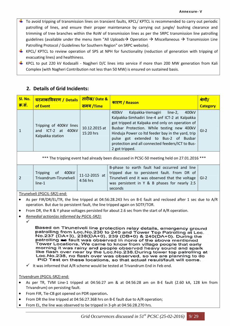
2. Details of Grid Incidents:
Sl. No.
कर.स. घटनाकावििरण / Details
of Event
तारीख/ Date &
समय /Time कारण / Reason
शरणी/
Category
1 Tripping of 400kV lines and ICT-2 at 400kV Kalpakka station
10.12.2015 at 15:20 hrs
400kV Kalpakka-Vemagiri line-2, 400kV Kalpakka-Simhadiri line-4 anf ICT-2 at Kalpakka got tripped at Kalpaka end only on operation of Busbar Protection. While testing new 400kV Hinduja Power co ltd feeder bay in the yard, trip pulse got extended to Bus-2 of Busbar protection and all connected feeders/ICT to Bus-2 got tripped.
GI-2
*** The tripping event had already been discussed in PCSC-50 meeting held on 27.01.2016 ***
2 Tripping of 400kV Trivandrum-Tirunelveli line-1
11-12-2015 at 4:56 hrs
B-phase to earth fault had occurred and line tripped due to persistent fault. From DR of Tirunelveli end it was observed that the voltage was persistent in Y & B phases for nearly 2.5 seconds
GI-2
Tirunelveli (PGCIL-SR2) end:
As per FIR/DR/EL/TR, the line tripped at 04:56:28.243 hrs on B-E fault and reclosed after 1 sec due to A/R operation. But due to persistent fault, the line tripped again on SOTF/TOR.
From DR, the R & Y phase voltages persisted for about 2.6 sec from the start of A/R operation.
Remedial action(as informed by PGCIL-SR2):
It was informed that A/R scheme would be tested at Trivandrum End in Feb end.
Trivendrum (PGCIL-SR2) end:
As per TR, TVM Line-1 tripped at 04:56:27 am & at 04:56:28 am on B-E fault (2.60 kA, 128 km from Trivandrum) on persisting fault.
From FIR, Tie-CB got opened on PDR operation. From DR the line tripped at 04:56:27.368 hrs on B-E fault due to A/R operation; From EL, the line was observed to be tripped in 3-ph at 04:56:28.270 hrs.
Annexure- V

Grid Occurrences discussed in 51st PCSC (25-02-2016) 10/ 29
Events relating to complete A/R operation and further tripping of Tie-CB on PDR operation were not shown either in DR or EL.
PGCIL (SR-II):
400kV Trivandrum- Tirunelveli line-1 tripped on B phase to earth fault. At Tirunelveli end, Line Auto reclosed
successfully. At Trivandrum end, Tie-CB auto-reclosed successfully but Main-CB did not auto reclose. The
reason for its failure was later traced to the problem in CB’s spring mechanism. As a result, the Main CB
opened after a delay of 2.5 seconds due to PDR operation.
Remedial action:
The problem with CB was proposed to be attended during the next approved shutdown on 8th March.
3 Tripping of 400/220 kV, 315 MVA ICT-2 at Chittoor
11-12-2015 at 7:12 hrs
ICT-2 tripped on OLTC oil surge relay trip at 400 kV Chittoor Substation. There was no fault in ICT
GI-2
As per FIR, ICT-2 tripped at 07:26 hrs on OLTC Oil Surge Relay trip.
As per DR, ICT-2 tripped at 07:22:53.995 on OLTC Buccholtz trip.
In EL, the events prior to 07:26:21.651 hrs were not recorded, by which time ICT-2 HV and LV CB’s were observed to be in OPEN condition.
Remedial action: APTRANSCO informed that the ICT tripped due to mal-operation of ABB-make OLTC oil surge relay. The
low-burden relay was replaced with high burden oil surge relay of AREVA make.
On this, SRLDC requested APTRANSCO to check for OLTC oil surge relays of other ICTs also.
4
Tripping of 400kV Alamathy-Tiruvalam line-1 and 400kV Alamathy-Vallur line-2
13-12-2015 at 22:42 hrs
400kV Vallur-Alamathy Line-2 got tripped from Vallur end during failure of Y-phase LA in 400kV Alamathy-Tiruvalam line. Protection at Vallur end tried for an auto-reclose and gave a 3 phase trip.
GI-2
*** At Alamathy SS, Tiruvalam – 1 & 2 are in same dia; Vallur 1 & 2 are in same dia. 400 kV Alamathy – Tiruvalam line-1: Alamathy (TANTRANSCO) end:
As per FIR/DR/EL/TR, the line tripped at 22:45:00.720 hrs on Y-E fault (failure of Y-ph LA), and then auto-reclosed after 1 sec due to A/R operation, but again tripped on SOTF/ TOR due to persistent fault.
Tiruvalam (TANTRANSCO) end:
As per FIR/DR/EL/TR, the line tripped at 22:42:32.496 hrs on Y-E fault due to A/R (CAT) operation. Around the time when the A/R relay PCS921 was about to give closing pulse, DT was received from the remote end causing the line trip in all 3-phases.
Time sync between Alamathy and Tiruvalam needs to be ensured.
400 kV Alamathy – Vallur line-2: Alamathy (TANTRANSCO) end:
As per FIR/DR/EL/TR, the line tripped in 3-ph at 22:39:59.286 hrs due to A/R lock-out and BAR (DR observations).
In TR, it was mentioned that line tripped in 3-ph due to DT receipt from Vallur end. Vallur (NTECL) end:
As per FIR/DR/EL/TR, the line tripped at 22:42:32.509 hrs on Y-E fault due to A/R operation. The line auto-reclosed after 1 sec, but again tripped on TOR due to persistent fault. (But from DR, A/R operation dead-time was observed to be 50 msec)
It was stated in FIR/TR that while Main-1 detected the fault in Zone-2, Main-2 detected the fault in Zone-1. Reasons for this line tripping? Why the other lines did not tripping during the event? SRPC:
It was noted that no representative from NTECL, Vallur came to attend the meeting.
Annexure- V

Grid Occurrences discussed in 51st PCSC (25-02-2016) 11/ 29
Prima facie, it appears that the Vallur end relay on Vallur-Alamathy line-2 over-reached for the fault on Alamathy – Tiruvalam line-1. However, the fact that Vallur end relay on Vallur-Alamathy line-1 had not operated during the tripping event indicates the need to review relay settings at Vallur end for Vallur-Alamathy D/C line.
Recommendations: NTECL, Vallur to furnish a report detailing the reasons for mal-operation of Vallur end relays for a fault on
Alamathy-Tiruvalam line-1, and remedial measures taken to PCSC forum. In the report, their preparedness for implementing line differential protection on Vallur-Alamathy lines may also be indicated.
5 Tripping of 400kV Jeypore-Gajuwaka line-2
24-12-2015 at 13:46 hrs
Y-B phase to earth fault had occurred in line and line auto-reclose successfully from Gazuwaka end. 9 minutes after occurrence of fault, breaker at Gajuwaka end tripped on direct trip receive from Jeypore end
GI-2
Gajuwaka (PGCIL-SR1) end:
As per FIR/TR, the line tripped at 13:46 hrs on Y-B fault, and auto-reclosed successfully. And then again tripped at 13:55 hrs due to DT receipt from Jeypore end.
As per DR/EL, the line tripped in three-phase at 13:46:07.492 hrs on Y-B fault, and auto-reclosed after 0.9 sec due to A/R operation.
DR & EL pertaining to DT receipt event at 13:55 hrs not furnished. Jeypore (PGCIL-ER1) end:
No FIR/DR/EL/TR furnished.
Remedial action: When enquired by SRLDC regarding operation of A/R for L-L-E fault, PGCIL (SR-I) informed that they would
check up the three-phase A/R scheme with the help of the Manufacturer during the next shut down process.
SRPC:
Like WRTS-I, SRLDC may provide User Id and Password to ERTS-I also to enable them to upload various tripping files in SRLDC’s web portal (TMS). PGCIL (SR-I) may also help in this regard.
6 Tripping of 400kV Sattenapalli-Vijayawada line
25-12-2015 at 3:01 hrs
Line tripped due to operation of over voltage protection at Vijayawada end and Direct Trip was received at Sattenapalli end
GI-2
Sattenapalli (APTRANSCO) end: As per FIR/Dr/EL, the line tripped at 03:00:50.848 hrs due to DT receipt from Nunna end.
From DR, it was however observed that only Y-phase voltage dipped to zero, and the remaining phase voltages were healthy. This means that the other end (Vijayawada) opened in single phase only.
Vijayawada (Nunna)(PGCIL-SR1) end:
As per FIR/TR, the line tripped at 3:01 hrs due to OVR, Stage-I operation. It was stated that (i) EL was not in working condition, and (ii) DR had not triggered. PGCIL (SR-I):
There is a problem with CB due to which all poles did not open upon receiving 3-ph trip command. So, PD relay had acted to open the CB ( R & B ph- poles).
Event Logger was defective, and its replacement was in the scope of APTRANSCO. To this, APTRANSCO informed that they would check up and revert soon.
Recommendations: PGCIL (SR-I), in co-ordination with APTRANSCO, to address the problem with CB at the earliest opportune time. APTRANSCO to take steps to replace the faulty Event Logger at Vijayawada (Nunna) SS.
7 Tripping of 400 kV Vemagiri-Gauthami-2
26-12-2015 at 00:01 hrs
Line tripped on operation of over voltage protection at Gauthami end and direct trip was
GI-2
Annexure- V

Grid Occurrences discussed in 51st PCSC (25-02-2016) 12/ 29
received at Vemagiri. FIR, DR and EL of Gouthami end was not available to validate the over voltage tripping.
Vemagiri (APTRANSCO) end:
As per FIR/DR/EL, the line tripped at 23:59:35.544 hrs due to DT receipt from Gautami end. Gautami end:
No FIR/DR/EL/TR furnished. SRPC:
When enquired about this tripping and the reasons for non-uploading of various tripping files, GVK Gautami personnel replied that they were not aware of such obligation.
Since, the same can also be expected to be the state of affairs with other IPP’s in the region, SRLDC may kindly arrange to provide User Id and Password all IPP’s in SR, so that they may directly upload various tripping files in SRLDC web portal in cases of trippings involving their stations.
Subsequently, tripping files (DR & EL) were received from GVK Gautami vide their e-mail dated 25.02.2016.
From DR/EL, the line tripped in 3-ph at 00:08:16.884 hrs. However, no over voltage condition was observed.
Recommendations:
GVK Gautami to adjust drop-off to pick-up ratio to > 98% for the Over Voltage relays at Gautami end on 400 kV Gautami – Vemagiri lines.
GVK Gautami to ensure time-sync of all DR’s & EL’s at Gautami Station with GPS
8 Tripping of HVDC Bhadrawati Pole-1
27-12-2015 at 4:38 hrs
Pole-1 tripped on DC differential protection;
Annexure- V

Grid Occurrences discussed in 51st PCSC (25-02-2016) 13/ 29
Annexure- V

Grid Occurrences discussed in 51st PCSC (25-02-2016) 14/ 29
9
Tripping of HVDC Bhadrawati Pole-1 & Pole-2
28-12-2015 at 4:48 hrs and 28-12-2015at 4:19 hrs
Pole-1 tripped on DC differential protection. Pole-2 tripped on Buchholtz surge trip.
Annexure- V

Grid Occurrences discussed in 51st PCSC (25-02-2016) 15/ 29
Remedial action: PGCIL (SR-I) informed that the Converter transformer was replaced in the first week of January, 2016.
Tripping on 28.12.2015 at 4:19 hrs:
As per FIR/TR, On 28.12.2015, at 04:19hrs, Pole-1 & 2 were carrying 100MW from W-->S direction. Pole-2 tripped on "28-12-2015 04:19:58.140 CWT22K198T T2W.BUCHOLZ SURGE - TRIP" alarm. From the
relay indications, it was found that the Buccholtz Surge - Trip was initiated from P2WY Converter Transformer.
Remedial action: After physical inspection, gas accumulated in the Transformer was released through air vents. Pole-2 was taken into service on 28.12.2015 at 05:10 Hrs.
10
Tripping of 400/220kV ICT-3 at N’Sagar
28-12-2015 at 9:04 hrs
Main CB (42852) of lCT-3 was out of service for Bus-1 shutdown. Tie CB (42952) tripped due to tripping of Bus Reactor at 09:14 Hrs (on Back up Impedance protection) causing isolation of ICT-3
GI-2
*** CB’s -428 (ICT’s Main-CB), 429, 430 (LR’s Main-CB) are in same dia. SLD:
Prior to tripping event, Main-CB (42852) was out of service for Bus-1 S/D.
As per FIR/EL/TR, Tie-CB (42952) tripped due to tripping of Bus Reactor at 09:14:18 hrs (on Back up Impedance protection) causing isolation of ICT-3.
From EL, Main-CBB (43052) LBB operated event was there along with Bus Reactor Impedance protection. From DR, ICT-3 tripped at 09:14:17 hrs due to HV side Tie-CB LBB operation. DR & EL were not configured to show events at msec level. PGCIL (SR-I): After availing Bus-1 shutdown, Bus CVT did not change from Bus-1 to Bus-2 due to problem in Change-over
contact relay. Due to this loss of Bus Voltage, the Backup Impedance protection of the Bus Reactor (BR) acted to trip CB-429
and CB-430.
Remedial action: The faulty Changeover contact relay was replaced with a spare one.
NLC:
Since backup impedance (BuI) protection of BR is supposed to act as back-up protection only in the event of actual fault occurrence, its operation merely on loss of voltage is not desirable. A suitable logic that allows operation of BuI protection only in cases of fault occurrence should be built in back-up impedance protection relay.
KPTCL:
Such a logic can probably check for the presence of negative and zero sequence currents. This will ensure presence of fault and allows the BuI protection to clear the fault.
However, it is important to see whether the relay supports building such extra logic. TANTRANSCO:
Annexure- V

Grid Occurrences discussed in 51st PCSC (25-02-2016) 16/ 29
The blocking logic can make use of 75 A and 75 B NC contacts for its operation.
Finally, it has been suggested to PGCIL (SR-I) to examine the feasibility of incorporating such a logic for Reactor’s backup impedance protection, and verify its efficacy on experimental basis by providing the same to any of its reactors.
SRPC:
When enquired about LBB-operation of Main-CB and Tie-CB events as recorded in EL, PGCIL (SR-I) replied that it was a legend problem, assured that it would be rectified.
11 Tripping of HVDC Gazuwaka Pole-2
31-12-2015 at 9:06 hrs
HVDC pole-2 tripped on operation of ‘High harmonic trip’. All filters of Pole-2 got tripped on ‘resistive thermal overload trip’
As per FIR/DR/EL/TR:
At 09:06 hrs, Pole-2 tripped on operation of "High Harmonic trip". At the same time "Ferro Resonance" was also detected on East side. It was observed that all the filters of Pole-2 tripped on "Resistive thermal overload Trip".
The in-service filters of Pole-I also tripped on 3 can failure trip. However, due to coming into service of the available 01-filter of HVDC Pole-I, it remained in Service.
PGCIL (SR-I):
Remedial action: The pole tripping due to harmonic inrush phenomenon (predominantly 3rd and 5th harmonics) was had
been referred to ALSTOM for suitable action.
12 Tripping of 400/220kV ICT-3 at Sriperambadur
31-12-2015 at 17:18 hrs
ICT tripped due to suspected mal-operation of pressure relief device
GI-2
As per FIR/TR, ICT-3 tripped at 17:18 hrs due to mal-operation of B-phase unit OLTC PRV. Wrong operation was attributed to PRV flag mechanical sluggishness. HV-3(1652) breaker, 1752- TIE breaker and LV-3(1852) breaker go tripped.
Remedial action: ICT-3(400/230KV) put back into service after rectifying the mechanical sluggishness of the B-ph unit of
OLTC PRV flag by charging the HV-3 Breaker (1652) at about 18.49, LV-3 Breaker (1852) 18.50 hrs, and TIE Breaker (1752) at 18.51hrs.
13
Tripping of 220 kV Ambewadi-Ponda line-1
01-01-2016 at 13:30 hrs
line tripped on a transient fault in B-phase and DEFR had operated and cleared the fault. Not much dip in voltage was observed in DR, hence it is suspected that a high resistance fault had occurred in line
GI-1
As per FIR/TR, the line tripped at 13:17 hrs on B-E fault due to DEFR operation. As per DR/EL, the line tripped at 13:17:38.020 hrs due to DEFR operation. From DR, no appreciable dip in any of the phase voltages was noticed. Also R & Y phase currents got
reduced 50 msec after DEFR start before finally tripping of all three poles after 900 msec (from DEFR Start). As this kind of pattern was observed in the past trippings also, this owes explanation from KPTCL.
Remedial action: KPTCL informed that 220kV Ambewadi-Ponda lines are passing through dense forest area and subjected to
very high resistive faults. Resistive reaches in distance relays are revised in order to enable primary protection to clear the faults. Revised settings adopted during January 2016.
14
Tripping of 400kV Vijayawada-Gajuwaka line-1
02-01-2016 at 07:09 hrs
Line tripped on a B-phase to earth fault. Line auto-reclosed at Gajuwaka end and tripped from Vijayawada end. A/R lockout and pole discrepancy trip was observed from EL of
GI-2
Annexure- V

Grid Occurrences discussed in 51st PCSC (25-02-2016) 17/ 29
Vijayawada substation
Gajuwaka (PGCIL-SR1) end:
As per FIR/DR/TR, the line tripped at 07:09:11 hrs on B-E fault due to A/R operation and auto-reclosed successfully after 1 sec.
It was stated that EL had not been triggered for the event. Vijayawada (PGCIL-SR1) end:
As per FIR/TR/DR, the line tripped at 07:09:15.223 hrs on B-E fault due to A/R operation, but failed to auto-reclose successfully.
From EL, the line tripped at 07:10:27.311 hrs on B-E fault due to A/R operation. However, the line failed to reclose, so PD relay acted to open the other two phases at 07:10:29.940 hrs.
Complete A/R operation and PDR operation were not shown in DR.
Time-sync between DR and EL at Vijayawada needs to be ensured. PGCIL (SR-I):
This line was connected through CB-2252 (BHEL-make) and CB-2252 (CGL make). However, only the CB-2352 was in healthy condition.
It was noticed that prior to this tripping event, the line had tripped multiple times with successful A/R operation. This could have brought CB-2352 on to verge of proper operation, and might have resulted in A/R loc-out in the instant case.
Remedial action: PGCIL (SR-I) informed that the line tripped on B-E fault. A/R attempted but un-successful due to persistent
fault. Thorough patrolling of line carried out and no abnormality found. Heavy fog and mist observed on the day of tripping may be the reason for fault.
15
Tripping of Gajuwaka Pole-1
03-01-2016 at 15:51 hrs and at 18:10 hrs
At 15:51 hrs, HVDC Pole-1 tripped due to “line side Ac O/V fault’’ and “valve winding AC O/V fault”. At 18:10 hrs Pole-1 tripped on GUPS redundancy exceeded
Tripping at 15:51 hrs:
Tripping at 18:10 hrs:
Annexure- V

Grid Occurrences discussed in 51st PCSC (25-02-2016) 18/ 29
16
Tripping of 400kV VTPS-Sattenapalli line-1 and 400kV Srisailam-Sattenapalli line
03-01-2016 at 23:58 hrs
400kV Satenapalli-Srisailam line tripped on R-phase to earth fault in zone-1.line did not auto reclose. 400kV VTPS-Satenapalli line-1 tripped on operation of over-voltage protection at Satenapalli end during fault in 400kV Srisailam-Satenapalli line
GI-2
400 kV Srisailam – Sattenapalli line-1: Sattenapalli (APTRANSCO) end:
As per FIR/DR/EL, the line tripped (in 3-ph) at 23:58:00.845 hrs on R-E fault due to DPR, Z1 operation. Srisailam (TSGENCO) end:
As per FIR/DR/EL, the line tripped at 23:57:04.841 hrs on R-E fault due to DPR, Z1 operation. 400 kV VTPS – Sattenapalli line-1: Sattenapalli (APTRANSCO) end: As per FIR/EL, the line tripped at 23:58:10.092 due to OVR operation.
From DR, the line tripped in 3-ph at 23:58:00.890 hrs due to Group-B 3-ph trip. SRLDC suggested APTRNASCO to ensure Drop-off to Pick-up ratio of OV relay above 98%. VTPS (APGENCO) end:
It was noted that no APGENCO representative came to attend the meeting. Also no tripping files (FIR, DR, EL, TR) had been furnished even after elapse of two months, which
constitutes an inexcusable violation of Regulation 5.2 (r) of IEGC. TSGENCO:
As 400 kV Srisailam LB is an underground generating station, a UG Cable of length around 1 km has been laid from Power House to the Switchyard to transmit power. From Switchyard, various transmission lines ensue. As the effective lines are a combination of UG cable and Overhead Transmission line, A/R feature has not been envisaged on any of these lines as it may create problem for the cable in case of permanent fault.
On this, it has been decided to seek the views of NLDC and examine the practices adopted by the Utilities transmitting power from their plants in similar way.
In this context, the general logic to be adopted for providing A/R on the transmission lines (220 kV & above) emanating from a generating station (Hydro/ Thermal/ Nuclear) has been deliberated. And after thorough discussion, PCSC forum has agreed to adopt the master-slave single-phase auto-reclosure logic for implementing A/R on the lines emanating from a generating station as explained below:
“In this, after a line got opened from both ends (generator end & remote end) on A/R operation, the remote end will be auto-reclosed as usual after the elapse of its dead-time (say, 1 sec). However, the generator end relay will check for the line voltage after elapse of an elongated dead time (say 1.3 sec; here the additional 0.3 sec has been included as a safety time margin). If
Annexure- V

Grid Occurrences discussed in 51st PCSC (25-02-2016) 19/ 29
the line voltage so sensed is healthy & normal (which implies that the fault has already been cleared), then generator end will be auto-reclosed; else 3-ph trip will be given at generator end to open the other two phases.”
17 Tripping of HVDC Bhadrawati pole-1
09-01-2016 at 5:08 hrs
Pole tripped on Thyristor redundancy lost and GUPS redundancy exceeded
As per FIR/TR of Gajuwaka (PGCIL-SR1): On 09.01.2016, at 05:08hrs, Pole-1 & 2 were carrying 1000MW,W-->S direction. Pole-1 tripped on
"VBE1W.VALVE POWER SUPPLY UNIT- LOW" & "VBE1W.VBE OPERATING STATE - TRIP". From the MPM, it was found that "Thyristor Redundancy Lost" & "GUPS redundancy Exceeded" alarms were
appearing in P1WB-YDLV valve.
Remedial action: During investigation of TPB alarms, 03 Nos of Thyristors found faulty in P1WB-YDLV valve. The redundancy
lost alarm was attended by replacing Two Nos faulty Thyristors in P1WB-YDLV-T4-L1 & P1WB-YDLV-T4- L8. Pole-1 was taken into service on 09.12.2015 at 11:08 Hrs.
18 Tripping of ICT-2 at Kayathar
09-01-2016 at 15:52 hrs
ICT tripped due to mal-operation of oil surge relay (OSR)
GI-1
As per FIR furnished by Kayathar (TANTRANSCO), ICT-2 tripped at 15:52 hrs due to OSR operation. It was stated that water droplets and consequent formation of Copper Oxide found inside the OSR of R & B phases resulted in shorting of the contacts, and caused OSR operation.
Remedial action: Water droplets entry path to OSR Relay was arrested and properly covered.
19 Tripping of 400/220kV ICT-2 at Gooty substation
12-01-2016 at 16:27 hrs
ICT tripped due to mal-operation of differential protection
GI-2
As per FIR/TR, ICT-2 tripped at due to operation of Differential protection. From DR, the tripping occurred at 16:20:29.639 hrs due to operation of Differential protection. From EL, the tripping occurred at 16:24:05.620 hrs due to operation of Differential protection. Time-sync between DR and EL needs to be ensured.
Remedial action: PGCIL (SR-I) has informed that ICT-2 tripped on mal-operation of differential protection (P643). As it has
got something to do with internal problem of the relay, the issue has been referred to its OEM, M/s Alstom.
20
Tripping of 400kV Gazuwaka pole-1 and 400kV Jeypore-Gazuwaka line-2
12-01-2016 at 21:28 hrs
Pole-1 blocked due to Low DC current during tripping of 400kV Jeypore-Gazuwaka line-2 due to a permanent fault.
GI-2
Tripping of 400 kV Gajuwaka-Jeypore line-2: Gajuwaka (PGCIL-SR1) end:
As per FIR/DR/EL/TR, the line tripped at 21:28:01.918 hrs on B-E fault due to 3-ph A/R operation. The line auto-reclosed successfully after about 1 sec, but tripped again on TOR due to persistent fault.
Remedial action PGCIL (SR-I) informed that the line tripped on Y-N fault. A/R attempted but un-successful due to persistent
fault. Thorough patrolling of line carried out and no abnormality found. Heavy fog and mist observed on the day of tripping may be the reason for fault.
Jeypore (PGCIL-ER1) end:
No Files (FIR/DR/EL/TR) furnished. Tripping of Pole-1:
Annexure- V

Grid Occurrences discussed in 51st PCSC (25-02-2016) 20/ 29
PGCIL (SR-I):
Remedial action: The issue of pole block on low DC current has been taken up with its OEM, M/s Alstom. A thorough maintenance check has been proposed in next shutdown during which various contact
resistances will also be checked for correctness.
21 Multiple tripping at 400kV Guttur sub-station
17-01-2016 at 18:53 hrs
Failure of Lightning Arrestor of Y-phase Line Reactor of 400kV Guttur-Hiriyur line-1 and line tripped on distance protection Zone-1. Bus-bar protection of 400kV Bus-2 at Guttur substation also got operated during the event sensing this through fault. 400/220 kV ICT-1 & 2 at Guttur, 400kV Kaiga-Guttur-2, 400kV Guttur-Narendra-2, 400kV Guttur-Hiriyur-2 and 400kV Guttur-Munirabad which are on 400kV Bus-2 got tripped during the incident. 400kV Guttur-Narendra-1 which was on Bus-1 also tripped at the same time.
GI-2
Bus configuration of 400 kV Guttur Substation of KPTCL is Double Main & Transfer Bus scheme. Kaiga – 1&2, Hiriyur_PG – 1&2, Narendra_PG – 1&2, Munirabad-1, and Jindal-1 are the 400 kV feeders
emanating from 400 kV Guttur SS. SLD:
400 kV Guttur – Hiriyur_PG line-1: Guttur (KPTCL) end:
400 kV Bus -2
JSW
220kV bus
Hiriyur PGCIL 2 X 180MW
390MW
311MW
***Fault was failure of Y phase LA of
Hiriyur line-1 reactor
2 X 315
MVA
Munirabad
41MW
Narendra
2 X 37MW
Kaiga
400kV Bus-1
1
2
1
2
1
2
2X162MW
Annexure- V

Grid Occurrences discussed in 51st PCSC (25-02-2016) 21/ 29
As per FIR/EL/TR, the line tripped at 18:39:28.771 hrs on Y-E fault due to A/R operation. The line tried to auto-reclose after 1 sec but tripped again due to persistent fault. It was stated that the failure of line reactor’s Y-ph lightning arrestor had caused the line tripping.
From the DR furnished, operation of A/R was not clear. Hiriyur (PGCIL-SR1) end:
As per FIR/EL/TR, the line tripped at 18:53:25.354 hrs on Y-E fault due to A/R operation. The line tried to auto-reclose after 1 sec but tripped again due to persistent fault & DT receipt from Guttur end.
400 kV Guttur – Hiriyur_PG line-2: Guttur (KPTCL) end:
As per FIR, the line tripped at 17:39:29 hrs due to BBP operation. DR & EL not furnished. Hiriyur (PGCIL-SR1) end:
As per FIR/DR/EL/TR, the line tripped at 18:53:26.036 hrs due to DT receipt from Guttur end. 400 kV Guttur – Narendra_PG line-1: Guttur (KPTCL) end:
As per FIR, the line tripped at 18:47:54 hrs due to BBP operation. DR & EL not furnished. Narendra (PGCIL-SR1) end:
As per FIR/DR/EL/TR, the line tripped at 18:53:26.812 hrs due to DT receipt from Guttur end. 400 kV Guttur – Narendra_PG line-1: Guttur (KPTCL) end:
As per FIR, the line tripped at 19:16:55 hrs due to BBP operation. DR & EL not furnished. Narendra_PG end:
As per FIR/DR/EL/TR, the line tripped at 18:53:26.812 hrs due to DT receipt from Guttur end. Tripping of ICT-1:
As per FIR, ICT-1 tripped at 19:01:00 hrs due to BBP operation. DR & EL not furnished. Tripping of ICT-2:
As per FIR, ICT-2 tripped at 19:35:36 hrs due to BBP operation. DR & EL not furnished. 400 kV Guttur – Munirabad (Guddadahalli) line: Guttur (KPTCL) end:
As per FIR, the line tripped at 19:01 hrs due to DPR, Z4 operation. Munirabad (PGCIL-SR1) end:
As per FIR/TR, the line tripped at 18:53 hrs on Y-E fault due to DPR operation.
It was stated that DR & EL data were not available. KPTCL:
Bay arrangement prior to fault was as follows: Bus-1: Kaiga-1, JSWEL, Narendra-1
Bus-2: Kaiga-2, Narendra-2, Munirabad, Hiriyur 1 &2, ICT-1 &2
400kV Hiriyur-1 tripped on M-I&II, Zone-1, YN, 148.5meters, 14.24kA. A/R operated but unsuccessful due to persistent fault (fault current of 21.5kA).
Reason: Y phase LA of Hiriyur -1 line reactor failed during the instance.
Annexure- V

Grid Occurrences discussed in 51st PCSC (25-02-2016) 22/ 29
Analysis: Single phase to Earth fault was sensed in Hiriyur -1 line. Y pole was opened and close command issued
after dead time. As per the scheme 3-phase trip would have been issued as the fault is persisting due to line reactor LA failure. However bus bar protection operated and lines and ICTs connected to bus-1 got tripped during the instance.
Tripping of 400kV Guttur-Narendra-1 connected to bus-1 during the instance was analysed due to wrong selection of trip bus (trip bus 2 was selected in CRP).
Remedial action: Several tests were done to analyze the root cause for operation of bus bar protection. But no specific
reason could be identified. Hence it is suspected that momentary arcing in some weak insulator strings in the bus might have
triggered bus differential protection. Action will be taken to test insulators strings in the bus. KSEB:
Here, BBP relay (RADHA) is a high impedance differential relay. Sometimes, the relay may mal-operate due to the presence of magnetizing current. If primary current pick-up, I(op), is set low, then it may so happen that the sum of the magnetizing currents from each core may exceed this value for heavy fault currents, and result in unnecessary BBP operation.
As CT supervision also cannot detect such differential magnetizing currents, it is necessary to check online the currents flowing through the relay terminals during normal operation; and based on that decision to replace the relay or putting additional external resistors may be taken.
NLC:
Generally mal-operation of high-impedance based BBP relays can be avoided by suitably revising voltage threshold (bia) settings.
APTRANSCO:
For fault analysis, first BBP relay indication should be checked to determine for which phase it had picked up. If it is also of Y-ph (same as the faulty phase), then no need to suspect insulator strings integrity; instead revising voltage threshold (bias) settings would do well to prevent such mal-operations.
For this, stabilizing resistor values to be used are to be determined based on maximum through-fault levels. SRPC:
Even though all 400 kV transmission elements (other than Guttur-Hiriyur line-1) have tripped almost at same time at Guttur end due to same cause, viz., BBP operation, the FIR’s submitted for these elements indicate a time-spread of two hours from 17:39 hrs to 19:35 hrs giving an impression that these have tripped at different times due to different causes, which is not correct.
Recommendations:
KPTCL to configure all DR’s and EL’s at 400 kV Guttur SS so that they will also get triggered for BBP operation. KPTCL to ensure time-synchronization of all DR’s and EL’s with GPS at their 400 kV Guttur SS.
22 Tripping of 400/220kV ICT-1 at Munirabad
18-01-2016 at 12:46 hrs
ICT-1 tripped during operation of tie bay breaker
GI-2
As per FIR/DR/EL/TR, ICT-1 tripped at 12:44:55.214 hrs due to 3-ph Group-A trip relay. [Main-CB (41052); Tie-CB (41152).]
From EL, Tie-CB Lock-out happened at 12:19:43 hrs. Then R & Y poles of the Tie-CB were observed to be in OPEN condition at 12:22.46 hrs. Then at 12:44:57 hrs both Tie-CB and Main-CB, “CB Manual OPEN” event was observed. Finally Main-CB got opened at 12:44:57 hrs due to 86A Trip relay operation.
EL was not configured to record events at msec level. PGCIL (SR-I):
It was a case of mal-operation. Around the tripping time, some works were being carried out. While attempting to isolate the DC earth fault, Master trip relay had generated a spurious signal to trip the breakers.
Recommendations:
Annexure- V
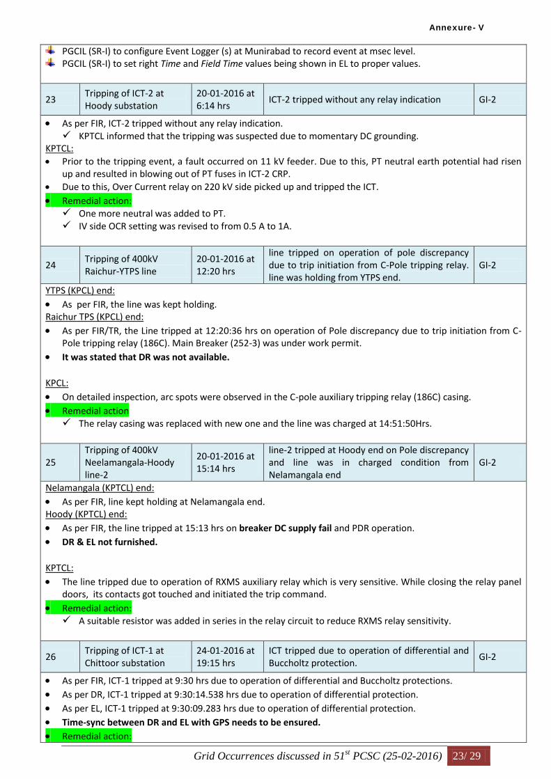
Grid Occurrences discussed in 51st PCSC (25-02-2016) 23/ 29
PGCIL (SR-I) to configure Event Logger (s) at Munirabad to record event at msec level. PGCIL (SR-I) to set right Time and Field Time values being shown in EL to proper values.
23 Tripping of ICT-2 at Hoody substation
20-01-2016 at 6:14 hrs
ICT-2 tripped without any relay indication GI-2
As per FIR, ICT-2 tripped without any relay indication. KPTCL informed that the tripping was suspected due to momentary DC grounding.
KPTCL: Prior to the tripping event, a fault occurred on 11 kV feeder. Due to this, PT neutral earth potential had risen
up and resulted in blowing out of PT fuses in ICT-2 CRP. Due to this, Over Current relay on 220 kV side picked up and tripped the ICT.
Remedial action: One more neutral was added to PT. IV side OCR setting was revised to from 0.5 A to 1A.
24 Tripping of 400kV Raichur-YTPS line
20-01-2016 at 12:20 hrs
line tripped on operation of pole discrepancy due to trip initiation from C-Pole tripping relay. line was holding from YTPS end.
GI-2
YTPS (KPCL) end:
As per FIR, the line was kept holding. Raichur TPS (KPCL) end:
As per FIR/TR, the Line tripped at 12:20:36 hrs on operation of Pole discrepancy due to trip initiation from C-Pole tripping relay (186C). Main Breaker (252-3) was under work permit.
It was stated that DR was not available. KPCL:
On detailed inspection, arc spots were observed in the C-pole auxiliary tripping relay (186C) casing. Remedial action The relay casing was replaced with new one and the line was charged at 14:51:50Hrs.
25 Tripping of 400kV Neelamangala-Hoody line-2
20-01-2016 at 15:14 hrs
line-2 tripped at Hoody end on Pole discrepancy and line was in charged condition from Nelamangala end
GI-2
Nelamangala (KPTCL) end:
As per FIR, line kept holding at Nelamangala end. Hoody (KPTCL) end:
As per FIR, the line tripped at 15:13 hrs on breaker DC supply fail and PDR operation. DR & EL not furnished. KPTCL:
The line tripped due to operation of RXMS auxiliary relay which is very sensitive. While closing the relay panel doors, its contacts got touched and initiated the trip command.
Remedial action: A suitable resistor was added in series in the relay circuit to reduce RXMS relay sensitivity.
26 Tripping of ICT-1 at Chittoor substation
24-01-2016 at 19:15 hrs
ICT tripped due to operation of differential and Buccholtz protection.
GI-2
As per FIR, ICT-1 tripped at 9:30 hrs due to operation of differential and Buccholtz protections. As per DR, ICT-1 tripped at 9:30:14.538 hrs due to operation of differential protection. As per EL, ICT-1 tripped at 9:30:09.283 hrs due to operation of differential protection. Time-sync between DR and EL with GPS needs to be ensured. Remedial action:
Annexure- V

Grid Occurrences discussed in 51st PCSC (25-02-2016) 24/ 29
APTRANSCO informed that ICT-1 tripped on differential protection due to internal problem in it. ICT was kept out of service.
3. Details of trippings due to Auto-Reclosure non-operation
Sl. No.
कर.स. घटनाकावििरण / Details
of Event
तारीख/ Date &
समय /Time कारण / Reason
शरणी/
Category
1
Tripping of 400kV Vijayawada-Nellore line-2
31-12-2015 at 12:02 hrs
Line tripped on Y phase to earth fault. Attempt for auto-reclose / Un-successful auto-reclose could not be established from the furnished DR/ EL.
GI-2
Nellore (PGCIL-SR1) end:
As per FIR/DR/EL/TR, the line tripped in 3-ph at 12:02:57.890 hrs on Y-N fault due to operation of Main-1 & Main-2 protections.
Vijayawada (PGCIL-SR1) end:
As per FIR/DR/TR, the line tripped in 3-ph at 12:03:30.300 hrs on Y-N fault due to DPR, Z1 operation (200 km). As per EL, the line tripped in 3-ph at 11:59:19.772 hrs on Y-N fault due to operation of Main-1 & Main-2
protections. PGCIL:
At Nellore end, A/R blocking command was persisting. This may be due to some problem in A/R relay contacts. Hence, it failed to reclose successfully.
Remedial action PGCIL (SR-I) informed that the line tripped on Y-N fault. Thorough patrolling of line carried out and no
abnormality found. Heavy fog and mist observed on the day of tripping may be the reason for fault. Recommendations:
PGCIL (SR-I) to furnish a report bringing out the reasons for non-operation of A/R during the tripping event, along with remedial taken, to PCSC forum.
2 Tripping of 400kV Vijayawada-Gajuwaka line-1
05-01-2016 at 04:18 hrs
line tripped on a R-phase to earth fault. Line auto-reclosed at Gajuwaka end and tripped from Vijayawada end.
GI-2
Gajuwaka (PGCIL-SR1) end:
As per FIR/DR/TR, the line tripped at 04:17:57 hrs on R-N fault, and successfully auto-reclosed after 1 sec due to A/R operation. (In DR, time-stamp down to msec, was not shown)
It was stated that EL had been not triggered during the event. Vijayawada (PGCIL-SR1) end:
As per FIR/DR/EL/TR, the line tripped at 04:17:59.637 hrs on R-N fault due to A/R operation. But the line failed to auto-reclose.
From EL, it was observed that the line tripped sat 04:19:15.034 hrs on R-N fault due to A/R operation. But Tie-CB (2352) A/R locked-out within 100 msec, and Main-CB (2452) locked-out within 900 msec. Subsequently the other poles of Main-CB got opened at 4:19:17.650 hrs on PDR operation, and that of Tie-CB got opened at 4:19:18.883 hrs on PDR operation.
PGCIL (SR-I):
Remedial action The line tripped on R-N fault. Thorough patrolling of line carried out and no abnormality found. Heavy fog
and mist observed on the day of tripping may be the reason for fault. They were planning to replace the existing insulators with CLR type insulators.
Recommendations:
PGCIL (SR-I) to furnish a report bringing out the reasons for non-operation of A/R during the tripping event,
Annexure- V

Grid Occurrences discussed in 51st PCSC (25-02-2016) 25/ 29
along with remedial taken, to PCSC forum.
3
Tripping of 400kV Jeypore-Gajuwaka line-1
12-01-2016 at 4:24 hrs
Line tripped on a R-phase to earth fault and A/R was under lockout. Line-1 had previously tripped at 3:24 hrs due to persistent fault during which it had attempted for an auto-reclose.
GI-2
Jeypore (PGCIL-ER1) end:
No files (FIR/DR/EL/TR) furnished. (The uploaded files were same as that of Gajuwaka). Gajuwaka (PGCIL-SR1) end:
As per DR, the line tripped at 04:24:55 hrs on R-E fault due to DPR operation. From EL, it was observed that the Main-CB (CWD Q51) A/R was under lock-out since 04:18:28.000 hrs; and
the Tie-CB (CWD Q50) was under lock-out since 04:24:48.397 hrs. As a result, when R-N fault occurred at 04:24:56.137 hrs due to the line did not auto-reclose, instead tripped in 3-ph due to DPR operation.
Time-sync between DR and EL needs to be ensured. PGCIL (SR-I):
Prior to this event, a fault occurred at 3:24 hrs during which time A/R operation occurred multiple times, due to which A/R contacts got stuck.
Remedial action PGCIL (SR-I) informed that the line tripped on R-N fault. The thorough patrolling of line carried out and no
abnormality found. Heavy fog and mist observed on the day of tripping may be the reason for fault. A/R relay has been replaced.
4 Tripping of 400kV IL&FS-Nagapattianam line-1
26-01-2016 at 13:03 hrs
Line tripped on R-phase to earth fault. Line auto-reclosed at IL&FS and failed to auto recloses at Nagapatinam.
GI-2
Is this line-1 or line-2?(Because as per ILFS, this is line-1; as per PGCIL-SR2, this is line-2) ILFS end:
As per FIR/DR/EL/TR, the line tripped at 13:03:49.150 hrs on R-E fault, and successfully reclosed after 1 sec due to A/R operation.
Nagapattinam (PGCIL-SR2) end:
As per FIR/DR/EL/TR, the line tripped in 3-ph at 13:03:49.201 hrs on R-E fault due to DPR, Z1 operation. From EL, “A/R lock-out from BCU” event was observed at 13:03:50.176 hrs. PGCIL (SR-I): A/R momentarily went into non-auto mode during updation of SCADA database. As the fault occurred during
this time, A/R failed to operate from Nagapattinam end.
For all the above cases of A/R non-operation, the time scale for the DR should be properly configured, say two sec, post triggering to capture complete A/R operation.
4. Details of trippings due to PLCC mal-operation
Sl. No.
कर.स.
घटनाकावििरण / Details
of Event
तारीख/ Date &
समय /Time कारण / Reason
शरणी/
Category
1 Tripping of 400kV Gajwel-Hyderabad
29-12-2015 at 6:11 hrs and 7:11 hrs
Line tripped at Gajwel end only due to suspected PLCC mal-operation at Gajwel end
GI-2
Tripping at 6.11 hrs: Hyderabad (PGCIL-SR1) end:
As per FIR, line kept holding from Hyderabad end.
Annexure- V

Grid Occurrences discussed in 51st PCSC (25-02-2016) 26/ 29
Gajwel (TSTRANSCO) end:
As per FIR, line tripped at 6.11 hrs due DT receipt from Hyderabad end. DR & EL not furnished. Tripping at 7.11 hrs: Hyderabad (PGCIL-SR1) end:
As per FIR, line kept holding from Hyderabad end. Gajwel (TSTRANSCO) end:
As per FIR, line tripped at 7.20 hrs due DT receipt from Hyderabad end. DR & EL not furnished. TSTRANSCO
The line tripped at Gajwel end only due to DT receipt. PLCC coupling device might have mal-operated, and they have proposed to carry out PLCC end-to-end
testing in co-ordination with PGCIL (SR-I). To this PGCIL (SR-I) also agreed.
DR and EL had not been triggered due to communication error. SRPC:
DR’s and EL’s of Gajwel SS had also not been submitted for the past trippings dated 02.11.2015. If that was also attributed to communication errors, there is an urgent need to check the integrity of all DR’s & EL’s at Gajwel SS.
Recommendations:
TSTRANSCO to check the integrity of all DR’s and EL’s, and sort out communication related issues at 400 kV Gajwel SS.
2 Tripping of 400kV Thrissur-Palakkad line - 1
04-01-2016 at 18:28 hrs
Line tripped at Thrissur end and was holding from Pallakad due to suspected PLCC mal-operation
GI-2
Palakkad (PGCIL-SR2) end:
As per FIR, line kept holding from Palakkad end. Thrissur (PGCIL-SR2) end:
As per FIR/DR/EL/TR, line tripped at 06:28:20.500 hrs due to DT receipt. Remedial action: PGCIL (SR-II) informed that the line tripped at Thrissur end only due to PLCC mal-operation. The faulty
P4LD Card (ABB make) had been replaced.
3 Tripping of 400kV Ramagundam-N’Sagar line-2
07-01-2016 at 21:07 hrs
Line tripped at Ramagundam end on direct trip receive and was holding from N’sagar end.
GI-2
N’Sagar (PGCIL-SR1) end: As per FIR, the line was kept holding from N’Sagar end. NTPC-Ramagundam end: As per FIR/EL, the line tripped at 21:07:10.980 hrs on receipt of Carrier Lockout Signal. It was observed that
85 L/O relay& Auto Reclose L/O relays operated.
From DR, line tripping occurred at 21:02:02.300 hrs. Time sync of DR & EL needs to be ensured
PGCIL (SR-I) informed that there was no counter increment at Nagarjunasagar.
Remedial action: NTPC-Ramagundam informed that the line tripped due to DT receipt and lockout relay had acted. PLCC
levels were checked and found ok.
It was agreed that NTPC and PGCIL (SR-I) would carry out PLCC end-to –end testing to check signal
Annexure- V

Grid Occurrences discussed in 51st PCSC (25-02-2016) 27/ 29
reception integrity.
4 Tripping of 400kV Neelamangala-Hoody line-2
20-01-2016 at 15:14 hrs
line-2 tripped at Hoody end on Pole discrepancy and line was in charged condition from Nelamangala end
GI-2
Same as 2.25
For all the above cases of PLCC mal-operation, the following shall be carried out by the concerned Constituents in co-ordination.
Healthiness of PLCC system components (hardware and software) at both ends shall be checked and faulty components shall be repaired/ replaced.
End-to-end communication for DT/ permissive & other signals may be ensured by testing at both the ends.
*****
Annexure- V

Grid Occurrences discussed in 51st PCSC (25-02-2016) 28/ 29
SLD of 230 kV CHECKANURANI SS of TANTRANSCO
Annexure- V

Grid Occurrences discussed in 51st PCSC (25-02-2016) 29/ 29
SLD of 220 kV PEENYA SS of KPTCL
Annexure- V

Meet
ing
No /
Index
Details of
Event
Date Reason PCSC Recommendations Utility
Responsible
for
implementa
tion
Status of Recommendations
as on 15-03-2016
Remarks
49/II/1
3
Tripping of
running Units 1
& 3 at
Rayalaseema
TPS of
APGENCO
31-10-2015
at 03:30 hrs
While synchronizing Unit-5 with grid, Bus bar
protection of 220kV Bus-1 operated which
resulted in de-energization of 220kV Bus-1.
This resulted in tripping of running Unit-
1&Unit-3, 220kV lines Pulivedula-1,
Yeralaguntla-1, Chinakampalli-1, Timmapura
In view of the availability of 25AX, APGENCO shall keep
synchronizing facility in auto-mode after getting it’s
operation verified by its OEM, M/s BHEL.
APGENCO Yet to be informed Pending
49/III/
4
Tripping of
400kV
Krishnapatnam-
Chittoor line-1
19-10-2015
at 07:49 hrs
R-phase to earth fault had occurred in line.
Chittoor end tried for auto-reclose. However,
due to persistent fault, breaker at Chittoor end
tripped. Krishnapatnam end relay did not try
for auto-reclose and gave a 3 phase trip as
observed from D.R
• APGENCO to make A/R functional on all lines emanating
from Krishnapatnam TPS by 10th December, 2015.
APGENCO Yet to be informed Pending
44/III/
2
Tripping of
400kV
Ghanapur-
Mamidapalli
line
15-04-2015
at 2:03 hrs
Line tripped at Mamidapalli end only and was
holding at Ghanapur. Overvoltage protection
had operated at Mamidapalli
TSTRANSCO to make DR
functional at Mamidipalli
TSTRANSCO TSTRANSCO informed vide their mail dated 24.06.15 that the existing relays
would be replaced with numerical relays in DPR works.
Pending
During testing of DC earth leakage, DC got
extended to bus bar protection relay. Hence bus
bar protection operated and tripped the 220KV
BUS connected transformers and feeders.
18-11-2015
at 11:20 hrs
Tripping of
220kV
Chittoor-
Tiruvalam
50/II/1
4
Pending Implementation of PCSC Recommendations (30th to 51st)
Andhra Pradesh42/II/3 Outage at
Regulapadu
station of
APTRANSCO
21-02-2015
at
00:49 hrs
Y-Ph Metering PT failed at 220KV
Ragulapadu Substation. Fault got cleared
by tripping of lines from remote ends.
APTRANSCO to furnish the remedial measures taken in
consequent to the tripping
incident along with the status of bus bar protection and bus
coupler at Regulapadu S/s.
A/R feature to be enabled on Regulapadu – Alipuira 220
kV inter-state line.
APTRANSC
O
Mail recieved on 22-08-2015:
APTRANSCOhas planned to commission ABB make ETL-41 type PLCC
terminal along with NSD-50 type protection coupler at Ragulapadu end towards
Alipura. vide our Ltr Dt 23-07-2015, it is requested KPTCL to arrange ABB
make ETL-41 cabinet with NSD-50 type protection coupler for establishing PLC
communication between Alipura- Ragulapadu.
KPTCL Mail recieved on 23-01-2016:
KPTCL is ready with ETL-41 cabinet with NSD-50 type protection coupler at
Alipur end.
APTRANSCO mail received on 24-02-2016:
Protection coupler equipment is ready at Ragulapadu end. Wave trap errection is
pending at Ragulapadu end. To maintain the ground clearenace structural
modification works are going on for errection of wave trap.
Pending
Telangana
PendingAPTRANSCO mail received on 24-02-2016:
220KV chittoor substation is a old 220KV substation with single bus operation.
Bus bar protection has both main & checkzone are in service.
APTRANSC
O
1.APTRANSCO to furnish SLD of 220/132 kV Chittoor
SS,
2. APTRANSCO to confirm whether 220 kV side is on
single-bus operation with only one main-zone. If so,
APTRANSCO shall examine the feasibility of providing
split-bus operation or multiple main-zones for bus bar
protection, and take necessary steps to implement it.
Annexure- VI
Page 1 of 20

48/II/5 Tripping of
400kV
Nagarjunsagar-
Mahboobnagar
line
07-09-2015
at 2:58 hrs
Line tripped on operation of over-voltage
protection at Mahboobnagar and direct trip
received at N’sagar station. DT receive was
observed in DR and EL of N’sagar station.
D.R/EL of Mahboobnagar was not furnished to
validate the overvoltage tripping
TSTRANSCO to furnish a detailed report on the tripping
event along with remedial measures taken to PCSC forum.
TSTRANSCO Yet to be informed Pending
48/III/
4
Tripping of
220kV Gajwel-
Shankarapally
line
20-09-2015
at 2:24 hrs
line tripped at Gajwel end on R-Phase to
ground fault. Reason for non-auto reclose
could be established as DR and EL of both
ends were not furnished
• TSTRANSCO to furnish a detailed report on the tripping
event along with remedial measures taken to PCSC forum.
TSTRANSCO Yet to be informed Pending
51/IV/
1
Tripping of
400kV Gajwel-
Hyderabad
29-12-2015
at 6:11 hrs
and 7:11 hrs
Line tripped at Gajwel end only due to
suspected PLCC mal-operation at Gajwel end
TSTRANSCO to check the integrity of all DR’s and EL’s,
and sort out communication related issues at 400 kV Gajwel
SS.
TSTRANSCO Yet to be informed Pending
Karnataka30/I/A RTPS
Tripping
incidents and
the Spl meeting
held
at RTPS on
13th and 14th
March 2014
Mar-14 Spl meeting held at RTPS on 13th
and 14th
March 2014
The PCSC forum recommended for replacement of
existing electromechanical relays with Numerical relays.
KPCL Mail recieved on 21-10-2015 and 23-11-2015:
1) Replacement of Old electromagnetic relays with Numerical relays has been
completed for RTPS-BTPS line & commissioned on 18.03.2014.
Raichur-PG1 & Raichur-PG2 lines have already retrofitted with numerical
relays.
The retrofitting of electromechanical relays with Numerical version for the
following lines/ICTs have been completed/commissioned as follows:
a) ICT-2 –Commissioned on 01-08-2015
b) ICT-1 ---Commissioned on 08-08-2015
c) Munirabad line--- Commissioned on 16-08-2015.
d) Mehaboobnagar line-- Commissioned on 09-09-2015.
2. Job order placed on 26.06.2015 on M/s Alstom T&D India Ltd. Chennai for
retrofitting of relays for all 220kV lines at RTPS.
3. Retrofit of existing bus bar(CAG-34) with numerical version– Budgetary
offers obtained and is under process.
Pending
47/II/6 Tripping of
400kV
Khammam-
KTPS line-2
30-07-2015
at 6:08 hrs
Y-phase to earth fault had occurred in line.
From Khammam end DR it was
observed that the relay after dead time tried for
auto-reclose. The fault was
persisting and relay gave a single phase trip
instead of a 3 phase trip after 1.25sec. R& B
pole voltage dip after 2 sec
possibly due to operation of pole discrepancy.
Auto-reclose close command observed after
2.5 seconds and all poles got closed.
1. TSGENCO to check the reclaim time of A/R and set it at
25 sec at KTPS.
2. TSGENCO to carry out PLCC end-to-end testing in
coordination with PGCIL (SR-I) for KTPS – Khammam
line-2; retrofitting of Protection Coupler may be carried out
based on the test results.
TSGENCO Yet to be informed Pending
Annexure- VI
Page 2 of 20

38/G
D/3.2
GD-1 at Guttur
Substation of
KPTCL
05-11-2014
at 11:42 hrs
Circuit breaker of 400kV Guttur-Hiriyur
line-1 failed at Guttur end while availing
shutdown for replacement of CVT. The
failure of breaker caused bus fault at Guttur.
KPTCL was requested to expedite the early implementation
of pending recommendations of:
1. Protection Audit (Phase-I & Phase-II)
2. PSAG-4, PSAG-5, and PSAG-8
KPTCL KPTCL mail received on 23-01-2016:
'The following works are attended at 400kV Guttur SS :
1. Replacement of Hiriyur-1 line, Bus Coupler, Tie Bus coupler breakers by new
Alstom make breakers (3 new CBs commissioned) recently.
2. New CVTs provided for 400kV Hiriyur line-1 and commissioned on
21.01.2016
Pending
39/I/5 Tripping of
400/220kV
ICT-2 at
Hoody
substation of
KPTCL
01-12-2014 Suspected mal-operation of 220kV side
Rphase
over current relay
1. PCSC forum recommended KPTCL to replace the relay
with a different make.
2. KPTCL was also requested to train the O&M personnel
adequately before performing any maintenance works to
avoid such unwanted trippings.
KPTCL Mail received on 27-05-2015 & 29-07-2015:
C&R panels of 500MVA ICT 1&2 will be replaced under scheduled R&M
works. O&M personnel are instructed to take sufficient care in order to avoid
unwarrented trippings.
KPTCL mail received on 23-01-2016:
New C&R panels(with numerical relays) erected for 500MVA ICT-1 &2 under
R&M work, which will be commissioned shortly.
Pending
16-07-2014 As reported directional over current relay of
ICT’s operated due to snapping of line
jumper in 220kV Lingapur line.
1. Bus bar protection shall be provided by asset owner (
i.e KPTCL).
2. Settings for main distance protection & Overcurrent
protection shall be examined and reviewed.
3. Time synchronization of the Substation shall be
ensured.
4. Correct DR shall be submitted to the SRLDC for trip
analysis.
KPTCL
38/G
D/3.5
GD-1 at Kadra
and Kodasalli
hydro power
station
13-11-2014
at 19:31hrs
A fault had occurred in 220 kV Kadra and
Kodasalli. As A result, de-energization of
220kV bus occurred at Kadra and
Kodasalli.
1. The PCSC forum requested KPCL to speed up the
installation of Numerical Distance Protection relay in
Kadra –Kaiga and Kodasalli –Kaiga.
2. The PCSC forum requested KPCL to submit the
implementation status of PSAG-10 recommendations within
a week’s time.
KPCL Mail recieved on 21-10-2015:
NIT floated on 5.5.15 through e-portal. Bid evaluation completed. LOA's issued
to M/s Schneider Electric Infrastructure Ltd. on 08.10.2015.
Mail recieved on 23-11-2015:
LOA's issued to M/s Schneider Electric Infrastructure Ltd. on 08.10.2015.
Engineering work is in progress.
Pending
34/III/
1
400kV
Raichur-BTPS
line
26-06-2014 Transient fault in R-phase.
Line did not auto reclose
A/R at BTPS end to be made operational within one
month
KPCL 1. A/R for 220kV lines enabled already.
2. Shut down of lines availed to commission the auto reclosing schme for 400
kV line at BTPS.
Mail recieved on 21-10-2015:
Timer relays have been received at site. A letter has been addressed to M/s
Alstom to complete the work on priority basis.
Mail recieved on 23-11-2015:
Commissioning of Autorecloser planned on 14, 15 & 16th of Dec-2015 subject
to availability of LC.
Pending
Mail recieved on 27-05-2015 (KPTCL):
1. KPTCL has taken action to provide bus bar protection to 220kV buses.
2. Over current relay Settings of ICTs to be reviewed by PGCIL.
Mail received on 29-07-2015 (KPTCL):
Initial Tendering stage
KPTCL Mail recieved on 23-01-2016:
Detailed estimate prepared for taking up the work. CEE, Transmission Zone,
Gulbarga will take up necessary procurement and further execution.
Pending
38/G
D/3.1
GD-1 at
Mahalingapura
Substation of
KPTCL
25-10-2014 Fault had occurred in 220kV
Mahalingapura-Narendra line-2. Due to the
failure of relay operation at Mahalingapura,
breakers at remote end tripped which
resulted in bus dead condition.
1. PCSC forum recommended KPTCL to replace the old
static distance protection relays with numerical relays.
2. PCSC forum also requested KPTCL to provide a broken
conductor alarm indication in Control Room.
3. Standing instruction needed to be given to the all
substation personnel for not changing the relay settings
without approval of RT/MRT wing.
KPTCL Mail received on 27-05-2015 (KPTCL) & 29-07-2015:
1.Existing Back up relays will be replaced by numerical type distance
relays.Procurement is in tendering stage. Remaining observations were
attended.
KPTCL Mail recieved on 23-01-2016:
Existing back up relays will be replaced by Main-2 protection. LOI issued M/s
Alstom for taking up the works.Remaining observations were attended.
Pending
34/I/6 400/220 kV
ICT-1 & 2 at
MUNIRABA
D
Annexure- VI
Page 3 of 20

40/IV/
1
220kV Sedam-
Tandur line
20-12-2014
at 22:20 hrs
Line tripped on Yphase to earth fault from both
the ends
KPTCL was requested to explore the possibility of
providing A/R feature to this line and submit the remedial
measures to the PCSC forum.
KPTCL KPTCL mail recieved on 23-01-2016:
Carrier protection is being restored for 220kV Sedam-Tandoor line at Sedam
end. After restoring the carrier protection , AR will be enabled.
Pending
42/I/1
(GD)
Complete
outage of
220kV Sedam
substation of
KPTCL
15-02-2015
at 14:24 hrs
Fault occurred in 220kV Sedam-Shahpur line 1. KPTCL to provide Bus Bar protection and LBB
protection at Sedam S/s and furnish
the status of their implementation to PCSC forum.
2. KPTCL to implement A/R feature on 220 kV Sedam-
Tandur inter-state line.
KPTCL Mail received on 29-07-2015:
1. Procurement of Bus bar and LBB protection is in the final tendering stage.
2. Action is being taken to restore the carrier protection for 220kV Sedam-
Tandoor line. AR will be enabled after restoration of PLCC.
Pending
42/I/2
(GD)
Complete
outage of
220kV
Ambewadi
substation of
KPTCL
12-03-2015
at 7:51 hrs
Fault in 220kV Ambewadi-Nagjheri line-2 1. KPTCL shall provide A/R feature on Ambewadi – Ponda
220 kV D/C inter-state line.
2. Till the completion of R&M works for bus bar and LBB
protection, KPTCL shall explore
the possibility of having split bus operation at Ambewadi
and submit the details of the
same to PCSC forum.
KPTCL Mail received on 29-07-2015:
1. Procurement of Bus bar and LBB protection is in the final tendering stage.
2. Action is being taken to restore the carrier protection for 220kV Sedam-
Tandoor line. AR will be enabled after restoration of PLCC.
Pending
41/I/1 GD-1 at 220kV
Kadra power
Station of
KPCL
16-02-2015
at 12:56 hrs
Triggering incident was B-phase to earth fault
had occurred in 220kV Kadra-Kodasalli line.
Line tripped from Kodasalli end only. 220kV
Kaiga-Kadra tripped in Zone-3 from Kaiga
end. Tripping of evacuating lines caused bus
shut down at Kadra hydro station.
1. KPCL to make functional the Main2 (EPAC) relay
with the help of KPTCL at the earliest.
2. KPCL to investigate the reason for DC fuse fail
during transient fault in 220kV Kadra-Kodasalli line
including the testing/ checking of DC supply cables, breaker
control cables, and trip coils.
3. KPCL to ensure supply for Main-1& Main-2
protections, Trip Coils (TC1, TC2) from separate battery
banks.
KPCL
40/I/1 GD-1 at 220kV
Ambewadi
Station of
KPTCL
22-12-2014
at 21:22 hrs
Triggering incident was B-phase to earth fault
in 220kV Ambewadi- Nagzari line-1. B-pole
of breaker did not open at Ambewadi end.
LBB protection not available at Ambewadi
end. All elements tripped on Zone-2 from
remote ends.
1. Till the completion of R&M works for bus bar and LBB
protection, KPTCL shall explore the possibility of having
split bus operation at Ambewadi and submit the details of
the same to PCSC forum.
2. KPTCL shall provide the details of the tripping of Supa
hydro station connected downstream from 110 kV bus.
KPTCL Mail recieved on 29-07-2015:
Action is being taken by KPTCL for operating Ambewadi in split bus mode.
Problem in bus coupler breaker is attended.Isolator overhaulling work is
completed.PTs are already provided to 220kV Bus-II. After commissioning of
Bus-II PTs, Ambewadi can be operated in split bus mode. Pending works will
be completed within a months time.
KPTCL mail recieved on 23-01-2016:
Bus-II PTs yet to be commissioned.Planned to complete before end of April-
2016.
Pending
Mail received on 28-05-2015:
1. Main-2 relays already installed and commissioned.
2. DC fuses are intact. Till date no such incidence occurred.
3. Possibility of DC-1 & DC-2 arrangement and splitting of DC will be
reviewed.
Mail received on 07-07-2015 , 21-10-2015 and 23-11-2015:
1. Completed.
2. Completed.
3. Possibility of DC-1 & DC-2 arrangement and splitting of DC will be
reviewed.
Pending
KPTCL mail received on 23-01-2016:
1. Bus bar protection panels pocured and erected at Sedam. Wiring , testing
,commissioning is being taken up.Planned to complete by April 2016.
2. Action is being taken to restore the carrier protection for 220kV Sedam-
Tandoor line. AR will be enabled after restoration of PLCC.
Pending41/I/4 Complete
outage at
220kV Sedam
Substation of
KPTCL (GD-
1)
27-01-2015
at 8.00 hrs
R-Phase to ground fault occurred on 220kV
Sedam-Shahpur line. Fault not cleared from
Sedam end due to stuck-breaker condition.
While the Sedam- Sahapur line tripped from
Shahapur end in Zone-1, the other 220 kv lines
from Sedam tripped at remote ends in Zone-2.
This caused complete outage of 220kV Sedam
substation.
1. KPTCL to provide Bus bar and LBB protections for
220 kV bus at Sedam S/s.
2. KPTCL to implement A/R feature on 220 kV Sedam-
Tandur inter-state line.
KPTCL
Annexure- VI
Page 4 of 20

43/II/1
4
Tripping of
400/220kV
ICT-1 at
BTPS
14-01-2015
at 1:09
hrs
ICT tripped due to operation of Over current
and Earth fault relay
KPCL to check the possibility of providing line differential
protection between RTPS and Yermarus stations.
KPCL Mail received on 07-09-2015 , 21-10-2015 and 23-11-2015:
Revised relay settings are awaited from KPTCL.
Revised relay settings furnished by KPTCL will be incorporated in co-ordination
with KPTCL shortly.
Pending
45/III/
12
Tripping of
400kV Raichur-
BTPS line
01-06-2015
at 01:02 hrs
line tripped on R-phase to earth fault. Line did
not auto-reclose
KPCL to make A/R operational on 400 kV RTPS – BTPS
S/C line at both ends.
KPCL Mail recieved on 23-11-2015:
Completed at RTPS end.
Pending at
BTPS end.
42/II/2 Tripping of
220kV
Chikodi-
Talandage and
220kV Chikodi-
Mudshingi line
20-02-2015
at
06:40 hrs
Lines tripped during test charging 220kV
Chikodi-Belgaum line-2 from Chikodi
end.
1. KPTCL to provide A/R feature on the 220 kV Chikkodi –
Talandage, and 220 kV Chikkodi –Mudashinge inter-state
lines.
2. KPTCL to carry out E/F relay coordination for Chikkodi -
Talandage and Chikkodi –
Mudashinge lines in coordination with Maharashtra.
KPTCL KPTCL mail received on 23-01-2016:
1) Replaced existing VXL by ABB make C&R panel for both interstate lines on
21.04.2015. The ABB Engineer visited 220KV Chikodi on 05.11.2015 for
enabling AR system to existing ABB make REL511 relay for both interstate
line, but AR system not enable due to internal cards faulty. Hence action is being
taken to replace the ABB,REL511 distance relays within a months time.
Pending
46/II/2
1
Trippings at
220kV Raichur
TPS
07-06-2015
at 01:35 hrs
1. KPCL to check the operation of anti-pumping relay on
220 kV side and keep it in healthy condition.
2. KPCL to provide manual reset to the 220 kV side master
trip relay.
3. KPCL to use both the 220 kV buses as main buses under
normal operation, and should go for single bus operation
only during emergencies.
KPCL Mail recieved on 23-11-2015:
1) Completed
2) Completed.
3) Two bus operation for 220kV buses : In place of existing CT switching relays,
High speed manual heavy duty change over switch of sufficient current capacity
will be retrofitted to all feeders at 220kV station and same will be operated
manually during changeover of feeder by one bus to the other and this
arrangement may facilitate to put both buses in service. Time required for this
retrofit is around 90days . However, this work will be taken up only after
retrofitting of electromagnetic relays with numerical relays for Main-2 protection
of all 220kV lines, for which work is in progress.
Pending
44/II/3 Tripping of
220kV
Kaiga-
Kodasalli
and 220kV
Kodasalli-
Nagjheri line- 1
22-04-2015
at
20:28 hrs
220kV Kodasalli-Nagjheri line-1 tripped from
Kodasalli end on operation of
distance protection, zone-2.
220kV Kodasalli-Nagjheri line-1&2 is kept
opened from Nagjheri end, hence fault
could not be cleared with carrier aided
protection. Backup earth fault relay at
Kaiga end got operated during the event and
resulted in tripping of 220kV Kaiga-
Kodasalli line from Kaiga end.
1. KPCL to check the possibility of implementing
Permissive Over Reach (POR) with Echo feature at
Kodasally end.
2. If the above is not possible, KPCL shall check the
possibility of keeping the 220kV
Kodasalli-Nagjheri lines OPEN at Kodasalli end and idle-
charged at Nagjheri end, and
implement the same.
KPCL Mail received on 07.07.2015:
The matter had been discussed with KPTCL. KPTCL recommended to keep
Zone-2 time lever to zero. If this is acceptable, then the same shall be
incorporated immediately.
Mail received on 07-09-2015 , 21-10-2015 and 23-11-2015:
The matter has been discussed with KPTCL. KPTCL recommended to keep
Zone-2 time lever to zero.
If this is acceptable to SRLDC, then the same shall be incorporated
immediately.Reply from SRLDC is awaited.
Pending
Annexure- VI
Page 5 of 20

47/III/
8
Tripping of
220kV
Ambewadi-
Ponda line-2
02-08-2015
at 13:20 hrs
Line tripped on a transient fault in B-phase.
There is no
provision for auto reclose.
47/III/
10
Tripping of
220kV
Ambewadi-
Ponda line-1
08-08-2015
at 10:51
hrs and 09-08-
2015 at
11:15 hrs
Line tripped on a B-phase to earth fault. Line
tripped as there is no provision for auto-reclose
47/III/
12
Tripping of
220kV
Ambewadi-
Ponda line-1
17-08-2015
at 13:20 hrs
Line tripped on a transient fault . There is no
provision for Auto reclose.
Till A/R is put into service on Ambewadi-Ponda line-1,
KPTCL to reduce Zone-2 time setting to zero sec. at
Ambewadi end.
KPTCL Yet to be informed Pending
PendingYet to be informedKPTCL KPTCL to revise distance relay settings at Nelamangala
end for 220 kV Nelamangala – Hebbal - Peenya line – 1 for
the effective line length of 17 km. These new settings can be
appropriately reviewed as and when the tie-arrangement at
Hebbal is done away with.
All connected 220kV lines and transformers
were taken on 220kV North bus as South bus
was under shut down for conversion of strung
bus to rigid bus and isolator replacement under
R&M works. Failure of HV side Y phase CT
of 150MVA Transformer-3 occurred at Peenya
Substation which resulted in operation of
Differential and HV REF protection. The
failure of CT also resulted in a 220kV bus fault
in North Bus.
27-09-2015
at 4:23:17 hrs
Complete
outage of
220kV Peenya
Substation in
Karnataka
48/I/2
(GD)
PendingYet to be informedKPTCLKPTCL to activate non-directional Over Current protection
with a time delay of 600-800 msec for Fuse
failure condition at Lingasugur.
220kV RTPS-Lingasugur line-2 tripped at
TPS end on operation of distance
protection zone-1. 400/220kV ICT-2 got
tripped on operation of earth fault
protection. 220kV RTPS-Lingasugur line-
1&3 tripped on distance protection
zone-2 and zone-3 respectively. Due to
tripping of ICT-2, the running units got
overloaded and it was mentioned that
under frequency occurred as units are
on load control. The Units got tripped
on under frequency.
06-08-2015
at 4:51 hrs
47/II/1
3
Tripping of
Unit-1&2
along with
400/220kV
ICT-2 at
Raichur TPS
Annexure- VI
Page 6 of 20

48/I/3
(GD)
Outage of
220kV
Ambewadi
station in
Karnataka
30-09-2015
at 10:41 hrs
220kV Ambewadi-Nagjheri line-2 tripped on B-
phase to earth fault. This resulted in loss of
supply to 220kV Ambewadi bus. 220kV
Ambewadi-Ponda line-1&2 were hand tripped
after deenergization of bus at Ambewadi.
KPTCL to fast-track providing A/R on all 220 kV lines
emanating from Ambewadi SS to prevent Station shut-down
on temporary faults.
KPTCL KPTCL mail received on 23-01-2016:
Will be complied in a months time.
Pending
48/I/4
(GD)
Complete
outage of 220
kV HSR
substation of
Karnataka
06-10-2015
at 16:32 hrs
All connected 220kV lines at 220kV HSR
substation i.e. Somanahalli, EPIP, Hoody and
Nagnathapura tripped during the incident.
Triggering incident was fault in 220kV HSR-
EPIP line
KPTCL to review distance relay settings at Naganathpura
SS in view of LILO arrangement at HSR Lay-out.
KPTCL KPTCL mail received on 23-01-2016:
ABB make REL 670 type distance relays provided to Somanahalli and hoody
lines. Planned to commission within 10 days.
Pending
49/II/1
5
Trippings at
Raichur TPS
12-11-2015
at 00:30 hrs
Running Unit-4, 5 and Unit-8 and 400kV
RTPS-Yeramaras TPS feeder got tripped due
to de-energization of both 400kV Bus-1&2 at
Raichur TPS
1. KPCL to carry out hot-line washing of RTPS-connected
lines regularly to avoid trippings due to fog and dust.
2. KPCL may see the feasibility of providing breaker
flashover protection at RTPS, and implement the same if
possible.
KPCL Yet to be informed Pending
220kV Nagjheri-Ambewadi line-1 tripped at
13:33 hrs due to B phase to earth fault.
Ambewadi was radially fed from Nagjheri
power station through 220kV Nagjheri-
Ambewadi line-2. Tripping of this line caused
220kV Bus shut down at Ambewadi and
remaining lines and transformers were hand
tripped
49/I/1.
3
(GD)
Complete
outage of
220kV
Ambewadi
Substation of
KPTCL
29.10.2015 at
14:34 hrs
PendingYet to be informedKPTCL1. KPCL to provide A/R on all 220 kV lines emanating from
Nagjheri PH.
2. KPTCL to provide A/R on all 220 kV lines emanating
from Ambewadi SS.
Annexure- VI
Page 7 of 20

17-01-2016
at 18:53 hrs
Multiple
tripping at
400kV Guttur
sub-station
51/II/2
1
PendingYet to be informedKPCL/
KPTCL
1. To avoid tripping of transmission lines on transient faults,
KPCL/ KPTCL is recommended to carry out periodic
patrolling of lines, and ensure their proper maintenance by
carrying out jungle/ bushing clearance and trimming of tree
branches within the RoW of transmission lines as per the
SRPC transmission line patrolling guidelines (available
under the menu item "All Uploads Operation
Miscellaneous Transmission Line Patrolling Protocol /
Guidelines for Southern Region" on SRPC website).
2. KPCL/ KPTCL to review operation of SPS at NPH for
functionality (reduction of generation with tripping of
evacuating lines) and healthiness.
3. KPCL to put 220 kV Kodasalli - Nagjheri D/C lines into
service if more than 200 MW generation from Kali Complex
(with Nagheri Contribution not less than 50 MW) is ensured
on sustained basis.
220kV lines from Nagjheri power house started
tripping from 11:00 hrs due to fault in lines.
The sequence of tripping is shown in SOE list.
At 12:33 hrs, 220kV Narendra-Ambewadi
lines-1&2 got tripped which resulted in loss of
evacuation path to Nagjheri station resulting in
tripping of running Units and complete outage
at Nagjhheri power station. 220kV Ambewadi
station also got de-energized due to tripping of
source feeders i.e. 220kV Narendra-Ambewadi-
1&2 and 220kV Nagjheri-Ambewadi-1&2.
22-02-2016
at 12:36 hrs
Complete
outage of
220kV
Nagjheri power
station and
220kV
Ambewadi
substation of
KPTCL
51/I/3
(GD)
PendingYet to be informedKPTCL 1. KPTCL to configure all DR’s and EL’s at 400 kV Guttur
SS so that they will also get triggered for BBP operation.
2. KPTCL to ensure time-synchronization of all DR’s and
EL’s with GPS at their 400 kV Guttur SS.
Failure of Lightning Arrestor of Y-phase Line
Reactor of 400kV Guttur-Hiriyur line-1 and
line tripped on distance protection Zone-1. Bus-
bar protection of 400kV Bus-2 at Guttur
substation also got operated during the event
sensing this through fault. 400/220 kV ICT-1
& 2 at Guttur, 400kV Kaiga-Guttur-2, 400kV
Guttur-Narendra-2, 400kV Guttur-Hiriyur-2
and 400kV Guttur-Munirabad which are on
400kV Bus-2 got tripped during the incident.
400kV Guttur-Narendra-1 which was on Bus-1
also tripped at the same time.
Annexure- VI
Page 8 of 20

48/I/1
(GD)
Disturbance in
220kV
Tamilnadu
system
05-09-2015
at 14:04 hrs
Complete outage of 230kV Palladam, 230 kV
Othakalmandapam S/s, 230 kV Coimbatore
S/s, 230 kV Thudialur and 230 kV
Sadayapalayam S/s
TANTRANSCO to take suitable measures like installing
more stub-towers along 230 kV OK Mandapam – Myvady
line to avoid excessive sag due to over-loading.
TANTRANS
CO
TANTRANSCO Mail received on 19-02-2016:
230kV Othakalmandapam - Myvadi feeder will be made LILO at Kongal Nagar.
Line restringing will be carried out along with the above proposal.
Pending
43/II/5 Tripping of
400kV
Alamathy-
SVChatram
line-1&2
and 400/230kV
ICT
at S.V.Chatram
29-03-2015
at
15:29 hrs
Tamil NaduLine-2 tripped on R-phase to earth fault.
Line autoreclosed at SVChatram end and failed
to reclose at Alamathy end. Bphase to earth
fault in line-1. Line tried for A/r but due to
permanent fault line did not reclose. ICT
tripped on operation of over flux protection.
PendingTANTRANSCO vide their mail dated 24.06.15 informed that different relays in
Main-I & Main-II would be ensured at the earliest.
Mail recieved on 24-07-2015:
Different relays in Main-I & Main-II will be ensured.
TANTRANS
CO
TANTRANSCO was requested to swap the relays between
two stations, so that
Main-1 and Main-2 will be of different make at each station.
Annexure- VI
Page 9 of 20

50/II/2 Tripping of
400kV
Alamathy-
S.V.Chatram
line-2
08-11-2015
at 10:48 hrs
Line tripped on D.T. receive on CHANNEL-2
at SV.Chatram end when the operator at
ALAMATHY S/S end tried to close Alamathy-
SVChatram-1&2 Feeder Tie Breaker.
Suspected DC earth fault had caused the
initiation of direct trip.
TANTRANSCO to provide A/R for 400 kV bay Tie-CB’s
at Alamathy SS and SV Chatram SS.
TANTRANS
CO
TANTRANSCO Mail received on 19-02-2016:
Instruction has been issued to enable Auto Reclosure feature in 400kV Tie
Breakers. The same will be informed to SRPC after completion.
Pending
49/I/1.
5
(GD)
Complete
outage of
S.P.Koil
station of
TANTRANSC
O and
generation loss
at MAPS
09-11-2015at
09:33 hrs
Fault had occurred in 230kV MAPS-S.P.Koil
feeder-1. LBB protection got operated as
breaker of this feeder was under lockout and
resulted in tripping of 230kV bus at S.P.Koil.
Unit-1&2 at MAPS due to loss of evacuating
feeders i.e. 230kV MAPS-S.P.Koil feeder-1&2
1. TANTRANSCO to ensure correctness of operation of
LBB relays at SP Koil.
2. TANTRANSCO & MAPS to furnish their respective
compliance report of the recommendations of to-be-
conducted PSAG-14 meeting at MAPS, Kalapakkam.
TANTRANS
CO
TANTRANSCO Mail received on 19-02-2016:
LBB scheme will be checked to ensure correctness of operation while availing
Line Clear.
TANTRANSCO and MAPS mail received on 25-01-2016:
Complaince report was submitted with respect to the recommendations given in
the Minutes of PSAG-14 Meeting.
Pending
50/I/3
(GD)
Complete
outage of
230kV
Mywadi station
of
TANTRANSC
O
21-12-2015
at 6:28 hrs
Busbar protection got operated for a fault in
230kV Mywadi-Anaikadavu line
1. TANTRANSCO to examine the feasibility of providing
two main-zone operation for bus bar protection by exploring
various alternatives like replacing existing bus-coupler CB
with a hybrid bus-coupler CB that comes with inbuilt CT,
replacing existing BBP relay with another suitable relay that
supports two main-zone operation, and implement the same.
TANTRANS
CO
TANTRANSCO Mail received on 19-02-2016:
Revision of Bus Bar Protection setting was carried out. The stabilizing voltage
setting was raised from 410 to 450 volts. After completing the necessary test, the
bus bar protection put in to service on 29.12.2015.
Pending
Annexure- VI
Page 10 of 20

50/II/1
7
Tripping of
400/230kV
Myvadi ICT-3
27-11-2015
at 17:26 hrs
400/230kV Myvadi ICT-3 tripped due to the
operation of 230 kV CB LBB protection at 230
KV bus (TNEB) of Myvadi station.
TANTRANSCO to check the LBB scheme for LV-3, and
furnish the remedial measures taken to PCSC forum.
TANTRANS
CO
TANTRANSCO Mail received on 19-02-2016:
LBB scheme will be tested while availing Line Clear.
Pending
PendingYet to be informedTANGEDCO NTECL, Vallur to furnish a report detailing the reasons for
mal-operation of Vallur end relays for a fault on Alamathy-
Tiruvalam line-1, and remedial measures taken to PCSC
forum. In the report, their preparedness for implementing
line differential protection on Vallur-Alamathy lines may
also be indicated.
400kV Vallur-Alamathy Line-2 got tripped
from Vallur end during failure of Y-phase LA
in 400kV Alamathy-Tiruvalam line. Protection
at Vallur end tried for an auto-reclose and gave
a 3 phase trip.
13-12-2015
at 22:42 hrs
Tripping of
400kV
Alamathy-
Tiruvalam line-
1 and 400kV
Alamathy-
Vallur line-2
51/II/4
PendingYet to be informedTANTRANS
CO
1. TANTRANSCO to provide split-bus operation with bus
sectionalizer CB for their 230 kV Madurai (Chekanurani)
SS.
2. TANTRANSCO to provide two main-zone operation for
the numerical BBP that is being commissioned.
3. TANTRANSCO to examine the feasibility of providing
Re-Trip feature for the LBB protection, and accordingly take
steps for implementing the same.
Fault had occurred in 230kV Madurai-
Sembatty line. Trip from distance relay was not
extended to breaker due to protection DC fail.
LBB protection got operated resulting in a
busbar trip at 230kV Madurai substation. All
elements got tripped as there is a single bus
operation at 230kV Madurai S/s
19-01-2016
at 11:56 hrs
Complete
outage of
230kV
Madurai S/s
(Chekanaurani)
of
TANTRANSC
O
51/I/1
(GD)
50/II/1
6
Kerala44/I/1
(GD)
Complete
outage of
Idukki Hydro
Power Station
(GD-1)
28-04-2015
at 12:30 Hrs
220 kV breaker of unit-3 at Idukki Power
house flashed and bus differential protection
acted. All Generators (6Nos.) along with all
220 kV feeders tripped during the incident.
1. KSEB to reduce sensitivity of REF protection
appropriately at Idukki PH.
2. KSEB to replace/ repair the faulty breaker.
3. KSEB to check the PLCC equipment at New Pallam and
inform the remedial measures taken to PCSC forum.
KSEB Mail recieved on 30-10-2015:
1. Purchase procedures is still in progress.
2. Replaced.
3. PLCC equipment Tested and found OK.
Mail recieved on 03-03-2016:
1. Even though repeated plans to have a joint inspection with M/s.ABB who is
the OEM of the relay panel for replacing the relays with numerical ones, the
same could not become successful. Finally, the inspection has been fixed on
15.03.2016. It has been planned to replace existing REF protection with low
impedance ones after retrofitting the numerical ones of OEM.
Pending
(Recomme
ndation
No.1)
PendingTANTRANSCO Mail received on 19-02-2016:
400kV S.V.Chatram - Alamathy -1 feeder 'C' phase jumper cut at Loc.No.178
from Alamathy end and created temporary fault with 400kV S.V.Chatram -
Alamathy -2 feeder 'A' phase jumper. Both feeders runs on the same tower.
PUTT Trip and AR successful at S.V.Chatram end. AR lockout at Alamathy
end. Direct Trip received at S.V.Chatram end due to wrong operation of TNC
switch at Alamathy end.
TANTRANS
CO
TANTRANSCO to check and ensure the healthiness of
A/R scheme at Alamathy end on 400 kV Alamathy – SV
Chatram line – 2.
400KV Aalmathy-S.V.Chatram line-1 tripped
on B-phase to earth fault. Line auto reclosed
and at both end subsequently A/R locked out
due to permanent fault.
400KV Alamathy-S.V.Chatram line-2 Line
tripped on R-phase to earth fault. Line
autoreclosed at S.V.Chatram and failed to auto-
reclose at S.V.Chatram end.
27-11-2015
at 15:35 hrs
Tripping of
400kV
Alamathy-
S.V.Chatram
lines - 1&2
Annexure- VI
Page 11 of 20

42/II/2
3
Tripping of
HVDC
Bhadravathi
Pole-1
18-03-2015
at
13:55 hrs
Pole tripped due to failure of auxiliary supply PGCIL (SR-I) to submit the compliance report on PSAG-11
recommendations to PCSC
forum.
PGCIL Reply received during 46th PCSC meeting:
Tertiary Transformer charged and auxiliary power for HVDC is being availed
from tertiary widings of ICT.
Pending
Yet to be informed Pending42/II/7 Tripping of
400kV
Jeypore-
Gazuwaka line-
1&2 and
tripping of
HVDC back to
back pole-
1&2 at
Gazuwaka
23-02-2015
at
13:34 hrs
HVDC pole-1 got tripped due to failure
of 4 no. power supply card. HVDC
pole-2 tripped on DC low voltage trip.
400kV Jeypore-Gazuwaka line-1&2
tripped due to operation of Over voltage
protection at Gazuwaka end.
PGCIL (SR-II) to submit the report of M/s ABB’s on
preventing supply card failures.
PGCIL
PGCIL34/I/7 HVDC
BHADRAVA
THI POLE 2
18-07-2014 As reported pole-2 tripped due on 5th
harmonic alarm.
1. Complete analysis of the faults and rectification/remedial
action taken to avert similar occurrence in the HVDC Back
to Back station shall be submitted.
2. The PCSC forum recommended PGCIL, SRTS-I take up
the issue with WRTS to submit the report as per IEGC
guidelines.
3. SRLDC is also requested to send a letter to WRLDC to
submit the reports to SR also.
4. Based on the SRTS/SRLDC correspondences, SRPC
would take it up with WR and PGCIL if the issue is not
getting resolved.
PGCIL Reply received during 46th PCSC meeting:
Being pursued with POWERGRID, WR-1
Pending
PGCIL Mail received on 02-09-2015:
The scheme was tested thoroughly found normal.
Pending to
check the
possibility
of re-trip
feature
PendingReply received during 46th PCSC meeting:
Operation is in-order as per OEM manual (ABB HVDC)
PGCILPGCIL (SR-I) to furnish the reasons for Converter
Transformer differential protection
operation for Pole-2 along with the remedial measures taken.
HVDC Pole-1 at Gazuwaka tripped due to
tripping of filter banks and Pole-2 tripped
due to operation of differential protection.
400kV Jeypore-Gazuwaka line-1 tripped
on over-voltage from Gazuwaka end.
14-03-2015
at
17:12 hrs
Tripping of
HVDC pole-
1&2
at Gazuwaka
and
400kV 400kV
Jeypore
Gajuwaka
line -1
42/II/2
2
43/II/2 Multiple
tripping
at 400/230kV
Hosur
substation
of Powergrid
26-03-2015
at 15:40 hrs
230kV Bus-2 at Hosur (PG) got
tripped as spurious initiation got
extended to LBB relay of 230kV
Hosur-Hosur(PG) line at Hosur(PG)
end due to shorting of contacts in
lockout relay. 400/230kV ICT-2, ICT-
3, 230kV Hosur-Vinnamangalam,
230kV Hosur(PG)-Hosur which were
connected to Bus-2 got tripped along
with bus coupler breaker
PGCIL (SR-II) to check the possibility of providing re-trip
feature in LBB relay.
Annexure- VI
Page 12 of 20

44/I/3
(GD)
765 kV
Raichur-
Sholapur line 1
&
2 tripped
24-05-2015
at 19:19 hrs
Tripped on Overload. 1. PGCIL to provide the status of healthiness of SPS contact
logic in SRLDC’s SCADA.
2. PGCIL to furnish the details of the implemented SPS-7
scheme including logic diagram to PCSC forum.
PGCIL Yet to be informed Pending
44/II/4 Tripping of
400kV
Ramagundam-
Hyderabad line-
3,
400kV
Hyderabad-
Malkaram line-
1 and 400kV
Bus-1
at Hyderabad
23-04-2015
at
15:11 hrs
400kV Ramagundam-Hyderabad line-3 at
ramagundam end only due to DT receive.
400kV Hyderabad-Malkaram line-1
tripped at Hyderbad end only and was
holding from Malkaram end. 400kV Bus-1 at
Hyderabad due to operation of bus
bar protection.
PendingYet to be informedPGCILPGCIL (SR-I) to check healthiness of PLCC panels at
Hyderabad SS, and repair/ replace
them, if necessary.
Annexure- VI
Page 13 of 20

44/II/6 Multiple
tripping at
Vemagiri
substation of
APTRANSCO
25-04-2015
at 10:04
hrs
400kV Vemagiri-Vijayawada line-1&3, 400kV
Vemagiri-Goutami line-2, 400kV Vemagiri-
Konaseema line-2 and 400/220kV ICT-2 at
Vemagiri tripped
during the incident. Triggering incident
was failure of B-phase L.A in 400kV
Vijayawada-Vemagiri line-1 at Vemagiri.
1. PGCIL (SR-I) to enable Auto reclosure feature at
Vijayawada end.
2. PGCIL (SR-I) to check distance relay settings for
Vijayawada – Vemagiri line 3, and
furnish a compliance report to PCSC forum.
PGCIL Yet to be informed Pending
44/II/8 Tripping of
400kV
Gooty-NPS
line-2
26-04-2015
at 13:16
hrs
R-phase to earth fault had occurred in
line. Lines auto-reclosed at gooty end
and later tripped due to DT receive from
NPS end.
PGCIL (SR-I) to coordinate STUB protection settings with
the distance protection time
settings at NPS.
PGCIL Yet to be informed Pending
45/II/2
1
Tripping of
400/220kV
ICT-1 at Gooty
Substation
03-06-2015
at 12:30 hrs
ICT tripped due to mal-operation of
differential relay
1. PGCIL to follow IS and CEA regulations while carrying
out maintenance work.
2. PGCIL to furnish a report on what caused the ICT-1
tripping including remedial measures.
PGCIL Yet to be informed Pending
46/II/1 Tripping of
400/220kV
ICT-2 at
Nagarjunsagar
Station
16-06-2015
at 18:12 hrs&
19:18 hrs
ICT-2 tripped due to mal-operation of 86B
relay due to suspected DC earth fault.
PGCIL (SR-I) to furnish a detailed report on ICT-2& Bus II
outage at 19.18 hrs on 16.06.2015 along with the remedial
measures taken.
PGCIL Yet to be informed Pending
46/II/4 Tripping of
400/220kV
ICT-2 at Gooty
substation
22-06-2015
at 13:06 hrs
At 220kV Gooty Switching Station, 220KV
Gooty Receiving Station feeder line side Y-
Phase jumper connected between line isolator
to boom resulting in a 220kV Bus fault. This
resulted in tripping of ICT-2 and 220kV
feeders connected to 220KV BUS-II.
PGCIL (SR-I) to furnish a detailed report as to what caused
LBB operation at 400 kV Gooty SS along with the remedial
measures taken.
PGCIL Yet to be informed Pending
45/II/1
5
Tripping of
765kV Raichur-
Solapur line-
1&2
03-05-2015
at 4:13 hrs
Lines tripped on transient fault. Auto reclose
was un-successful. SR &NEW grid separated
due to tripping of 765kV lines
To avoid tripping of transmission lines on transient faults,
PGCIL is recommended to carry out periodic patrolling of
lines, and ensure their proper maintenance by carrying out
jungle/ bushing clearance and trimming of tree branches
within the RoW of transmission lines as per the SRPC
transmission line patrolling guidelines (available under the
menu item "All Uploads Operation Miscellaneous
Transmission Line Patrolling Protocol / Guidelines for
Southern Region" on SRPC website).
PGCIL Yet to be informed Pending
PendingYet to be informedPGCIL1. PGCIL (SR-I) to submit the action taken report on the
measures suggested by their OEM.
2. PGCIL (SR-I) to check for the availability of Chatter
Disable feature in P141 and
configure it appropriately to block operation of REF
protection on DC fluctuations.
REF protection of Line reactor of
Nellore-1&2 and Tiruvalam line-1 maloperated
due to DC earth fault
25-04-2015
at
18:10 hrs
Tripping of
765kV
Kurnool-
Tiruvalam line-
1
and 765kV
Kurnool-
NPS-1
44/II/7
Annexure- VI
Page 14 of 20

47/II/1
1
Tripping of
HVDC
Bhadrawati
Pole-1
05-08-2015
at 10:53 hrs
Main pump-2 of valve cooling got
tripped during dip in 33kV auxiliary bus
voltage. Valve cooling flow got reduced
due to tripping of pump and resulting in
tripping of pole-1
PGCIL (SR-I) to furnish compliance report on PSAG-11
recommendations without further delay to PCSC
forum.
PGCIL Yet to be informed Pending
765 kV
RAICHUR -
SHOLAPUR 1
and 2
04-09-2015
at
19:25 hrs
Sholapur -1 and 2 Feeder got tripped at
Raichur end on operation of over current
protection in Main-1 distance relay and
holding from Solapur end on 04.09.2015 at
19:24:42 Hrs
765 KV
RAICHUR –
KURNOOL 2
04-09-2015
at
19:25 hrs
Kurnool -II Feeder got tripped on B-N fault
and holding from Kurnool end (successfully
auto-reclosed at Kurnool end) subsequently
tripped at other end on operation of Over
Voltage stg-1 protection at Raichur end on
04.09.2015 at 19:24 Hrs
49/II/4 Tripping of
400kV Gooty-
NPS line-1
13-10-2015at
10:15 hrs
Direct Trip was sent to NPS end of line-1
during opening of Main CB of Gooty-NPS line-
2 at Gooty end. This resulted in tripping of line-
1 at NPS and line was holding from Gooty.
Over voltage protection got operated at NPS
end and resulted in tripping of line
1. PGCIL (SR-I) to configure time scale resolution in Event
Logger to msec. at Nelllore PS (NPS) and furnish DR
corresponding to OVR, Stag-I operation at NPS end during
the tripping event.
2. PGCIL (SR-I) to ensure time-sync of DR’s and EL’s with
GPS at Gooty and NPS.
PGCIL Yet to be informed Pending
1. PGCIL (SR-I) to furnish a report detailing the sequence of
events including the remedial measures taken to PCSC
forum.
2. PGCIL (SR-I) to verify and ensure time-synchronizationof
DR& EL with GPS at both Gooty and NPS.
3. PGCIL (SR-I) to check and resolve,in co-ordination with
APTRANSCO, the professed Phase-Discrepancy that is
found to be occurring between 400 kV Gooty (PG) SS and
the surrounding 220 kV network of APTRANSCO in the
event of a fault.
Breaker at NPS end tripped on Direct Trip
receipt from NPS end. After 4 seconds, over
voltage protection operated at NPS end as
observed from EL, and direct trip was sent to
Gooty.
01-07-2015
at 09:59 hrs
Tripping of
400kV Gooty-
NPS line-1
46/II/1
3
28-07-2015
at 11.52.22
hrs.
Separation of
SR-grid and
NEW-grid
46/II/2
2
47/II/1
8
1. PGCIL (SR-I) to check the A/R scheme implemented
through BCU’s at all its GIS/ SAS substations for correct
operation.
2. PGCIL (SR-I) to ensure time-synchronization of DR &
EL of 765 kV Kurnool SS with GPS.
3. PGCIL (SR-I) to sort out the LEGEND ISSUE related to
tripping of the lines in the Event Logger of Raichur.
4. PGCIL (SR-I) to check & ensure the functionality &
healthiness of synchronization facility at Raichur end at the
earliest opportune time.
PGCIL Yet to be informed Pending
PendingYet to be informedPGCIL
PendingYet to be informedPGCIL1. PGCIL (SR-I) to obtain from PGCIL (WR-l) the reasons
for DT receipt from Sholapur end and furnish thesame along
with the remedial measures taken to PCSC forum.
2. PGClL (SR-I) to verify the logic implemented of SPS-1
and SPS-7 for the 76S kV Raichur - Sholapur link
byavailing the line shutdown at the earliest opportune time.
3. PGCIL (SR-I) to furnishthe details of the implemented
SPS-1 and SPS-7 schemes including their logicdiagrams to
PCSC forum.
Annexure- VI
Page 15 of 20

51/II/2
2
Tripping of
400/220kV
ICT-1 at
Munirabad
18-01-2016
at 12:46 hrs
ICT-1 tripped during operation of tie bay
breaker
1. PGCIL (SR-I) to configure Event Logger (s) at
Munirabad to record event at msec level.
2. PGCIL (SR-I) to set right Time and Field Time values
being shown in EL to proper values.
PGCIL Yet to be informed Pending
51/III/
1
Tripping of
400kV
Vijayawada-
Nellore line-2
31-12-2015
at 12:02 hrs
Line tripped on Y phase to earth fault. Attempt
for auto-reclose / Un-successful auto-reclose
could not be established from the furnished
DR/ EL.
PGCIL (SR-I) to furnish a report bringing out the reasons
for non-operation of A/R during the tripping event, along
with remedial taken, to PCSC forum.
PGCIL Yet to be informed Pending
51/III/
2
Tripping of
400kV
Vijayawada-
Gajuwaka line-
1
05-01-2016
at 04:18 hrs
line tripped on a R-phase to earth fault. Line
auto-reclosed at Gajuwaka end and tripped
from Vijayawada end.
PGCIL (SR-I) to furnish a report bringing out the reasons
for non-operation of A/R during the tripping event, along
with remedial taken, to PCSC forum.
PGCIL Yet to be informed Pending
41/II/1
2
Tripping of
400KV Coastal-
NTPL line
13-02-2015
at 22:54 hrs
Line tripped B-phase to earth fault and later
tripped on R-Y phase fault. From Coastal end
D.R, Y & B poles of breaker opened first and
R-pole appears to be opened on Pole
discrepancy.
CEPL to check A/R scheme at their end. CEPL Yet to be informed Pending
41/IV/
2
400kV
Tuticorin PS-
NTPL line
09-02-2015
at 03:17 hrs
Y-phase to earth fault had occurred in line.
Line auto reclosed at Tuticorin PS end and
failed to reclose at NTPL end.
NTPL to check A/R scheme at their end. NTPL Yet to be informed Pending
44/III/
4
Tripping of
400kV
Coastal
(CEPL)-
Tuticorin
pooling
station
20-04-2015
at 12:35 hrs
Line tripped at Coastal energen end only and
was holding from TTRNPS
CEPL to furnish a detailed report on this trip event to PCSC
forum.
CEPL Yet to be informed Pending
Others
50/I/2
(GD)
Complete
outage of
TPCIL power
station
30-12-2015
at 06:02hrs
Running units at Thermal Powertech power
Station tripped due to tripping of 400kV
Nellore pooling station (NPS)-TPCIL line and
400kV Nellore pooling station (NPS)-ECC line
1.PGCIL (SR-I) to furnish Action Taken Report on the
findings of OEM on relay mal-operation at NPS end on 400
kV NPS – NCCK line to PCSC forum.
2. PGCIL (SR-I) to appropriately configure Station Event
Logger at NPS to record events at msec interval.
3. PGCIL (SR-I) to carry out PLCC end-to-end testing in
coordination with TPCIL for 400 kV NPS –TPCIL line.
4.PGCIL (SR-I), MEPL, SEL, TPCIL & NCC to take steps
to provide line differential protection at their respective ends
on all 400 kV lines (except Gooty line) emanating from
Nellore Pooling Station, and furnish an action plan to
implement the same.
PGCIL Yet to be informed Pending
Annexure- VI
Page 16 of 20

46/II/3 Tripping of
400kV
Ramagundam-
Dichipalli line
21-06-2015
at 03:27 hrs
Line tripped on operation of overvoltage
protection at Ramagundam end and direct trip
was received at Dichipalli. Over-voltage
operation could not be established with D.R &
E.L submitted by Ramagundam station.
1. NTPC, Ramagundam to investigate the reasons for Over
Voltage alongside checking the drop off- to- pick-up ratio of
the OV relay.
2. The tripping is not as per the grading adopted for
Overvoltage, Stage-I protection (Grading is C2: 110% and 6
sec time delay) at Ramagundam. NTPC, Ramagundam to
check up the same.
NTPC Yet to be informed Pending
47/III/
2
Tripping of
400kV
Vemagiri –
GVK (JPD)
line-2
16-07-2015
at 17:02 hrs
R-phase to earth fault had occurred in line.
Line auto reclosed at Vemagiri end and failed
to reclose at GVK end.
GVK to put A/R into service at GVK Jegurupadu end on
400 kV GVK (Jegurupadu) – Vemagiri line-2.
GVK Yet to be informed Pending
48/II/1
6
Tripping of
400 kV Hassan
-Udupi line-1
05-10-2015
at 13:33
Line tripped due to B-E fault in Z2. Main 1
relay tripped in Z2. Three phase trip operated
at Hassan. Auto-reclose successful at other end
and line was charging from other end. Then
OV stage 1 picked up in Main2 relay and
operated in OV after the time delay
UPCL to furnish reasons for delayed operation of distance
relay in Zone-1 at their end, and the remedial measures
taken, if any.
UPCL Mail recieved on 19-11-2015 (UPCL):
The fault was of resistive nature, was sensed from Hassan end in Zone-2 reach.
The DR from UPCL indicates resistive high current prior to operation of Zone-1
in C Phase. This is seen as development of Zero sequence voltage and current
prior to Zone -1 operation.
The operation of single phase Z1 from UPCL end was correct followed by
successful AR operation.
Pending
51/II/7 Tripping of
400 kV
Vemagiri-
Gauthami-2
26-12-2015
at 00:01 hrs
Line tripped on operation of over voltage
protection at Gauthami end and direct trip was
received at Vemagiri. FIR, DR and EL of
Gouthami end was not available to validate the
over voltage tripping.
1. GVK Gautami to adjust drop-off to pick-up ratio to >
98% for the Over Voltage relays at Gautami end on 400 kV
Gautami – Vemagiri lines.
2. GVK Gautami to ensure time-sync of all DR’s & EL’s at
Gautami Station with GPS
GVK
Gautami
Yet to be informed Pending
PendingYet to be informedUPCL 1. UPCL to provide different make relays for Main-1 &
Main-2 at UPCL end on 400 kV UPCL – Hassan lines – 1 &
2.
2. UPCL to make GPS functional at their Station and ensure
time-sync of various DR’s and EL’s with GPS.
400kV Hassan-Udupi line-2 tripped on
Directional earth fault protection with Y-E
fault and direct trip was sent to Udupi end.
Directional Earth fault feature of Main-2 relay
at Hassan gave 3-ph trip after 2.6 seconds and
fault current in Y-phase was 1.1 kA. The
distance as well as DEF protection for 400kV
UPCL-Hassan line-2 at UPCL end did not
sense the fault. The generator transformer
backup earth fault protection (51N) had sensed
the fault and tripped both the running units at
UPCL leading to generation loss at UPCL
power station. Back up directional earth fault
protection at 220kV side of 400/220kV ICT’s
at UPCL did not sense the high resistance fault
in line-2
30-11-2015
at 17:22 hrs
Tripping of
400kV UPCL-
Hassan line-2
and running
Units-1&2 at
Udupi power
station
50/II/1
8
Annexure- VI
Page 17 of 20

36/II/8 400kV
Raichur-
Munirabad line
07-09-2014 B-phase to earth fault had occurred in line.
Line auto reclosed at Munirabad end and failed
to reclose at Raichur end.
KPTCL:
PD (pole discrepancy) time delay would be changed.
PGCIL /
KPTCL
Yet to be informed Pending
38/II/5 400kV
Ramagundam-
Hyderabad line-
4
27-10-2014 Line tripped on Bphase
to earth fault.
Line did not auto
reclose at Hyderabad
end due to
PLCCmal-operation.
Planned to replace the PLCC system within a week's time at
both the ends during the shutdown.
NTPC/
PGCIL
Yet to be informed. Pending
40/II/3 Tripping of
400
kV
TALAGUPPA
– HASSAN
line
01-01-2015
at
13:38 hrs
On account of R-phase to earth fault, line
tripped at Hassan end due to operation of
distance Zone-2 and non-receipt of
carrier. From D.R of Talaguppa end it is
observed that fault had occurred in Yphase.
1. PGCIL and KPTCL to ascertain the reason for the
phase discrepancy in the relay operation and take suitable
remedial measures.
2. KPTCL to check the PLCC operation at Talaguppa
end and submit the report to the PCSC forum.
PGCIL/
KPTCL
Mail received on 27-05-2015 (KPTCL) & 29-07-2015:
End to end testing of PLCC has been done and problem in the PLCC is
atttended. Phase discripancy in the relay operation is to be checked jointly.
Mail recieved on 02-09-2015:
Problem is in identification of phases at Talguppa end. To be rectified by M/s
KPTCL.
Pending
42/II/1 Tripping of
400kV Coastal-
Tuticorin PS
line
19-02-2015
at
16:37 hrs
Line tripped at Coastal end only
due to suspected PLCC maloperation
and was holding from
Tuticorin PS end. Running Unit at
Coastal energen also got tripped
during the event.
PLCC end-to-end testing shall be carried out by CEPL and
Tuticorin PS (PGCIL-SR II) by
06.04.2015.
CEPL/
PGCIL(SR-II)
Mail received on 02-09-2015 and 25-11-2015:
On 11.06.2015 PLCC testing carried out by M/s ABB Engineer. ABB suspects
that the problem is with frequency interference related issue, and suggested to
change to new frequecies.
Pending
with CEPL
Miscellaneous
39/I/2 Tripping of
400Kv
Ghanapur-
Mamidipally
line
22-12-14
at 10:52 hrs,
24-12-14 at
11:32
hrs,
24-12-14 at
16:16 hrs
Due to PLCC Mal-operation at HYD S/S end,
DT received at MMPLY end and line got
tripped.
PGCIL is requested check up with the manufacturer to
resolve the issue and submit remedial measures to PCSC
forum.
PGCIL/
TSTRANSCO
Mail received on 26-05-2015 from TSTRANSCO:
On 27-12-2014 PGCIL requested to arrange services of OEM(Manufacturer)for
identifying the problem. TSTRANSCO arranged the same on 06-01-2015 and
the manufacturer testing and concluded that the problem in not in the newly
erected digital protection coupler at both ends and the issue is related to relay
panel at Ghanapur. [OEM minutes enclosed]
Pending
42/II/1
8
Multiple
tripping at
Raichur
thermal
power station
of
KPCL
09-03-2015
at
06:36 hrs
400kV Raichur TPS-Raichur(PG) line-
1&2, 400kV Raichur-Mahboobnagar,
Unit#7 and ICT-2 at RTPS tripped
during the incident. B phase to earth
fault had occurred in 400kV Raichur
TPS-Raichur line-1
1. KPCL to review REF setting (DMT or IDMTL) for unit-7
by first week of April, 2015 and
inform the same to PCSC forum.
2. TSTRANSCO to furnish Mehaboobnagar’s DR and EL
and the reasons for distance relay
operation at their end within a week’s time.
3. PGCIL (SR-I) to rectify the issues relating to A/R
operation, relay reach (Z2), reverse reach
(Z4) and SOTF auxiliary contacts within a week’s time, and
submit the actions taken to
PCSC forum.
KPCL/TSTR
ANSCO/PGC
IL (SR-I)
Mail received on 26-05-2015 from TSTRANSCO:
It is found that the main-2 ABB make REL316 type distance relay was
defective and same was replaced with MICOM P444 by M/s.PGCIL on 23.04-
2015. After replacement of main-II, DR can be extracted from this relay. For EL
in to service, some field winding is pending which is being taken up in this
month.
Pending
Annexure- VI
Page 18 of 20

43/II/1
2
Multiple
tripping at
400kV
Raichur(PG)
and RTPS of
KPCL
11-04-2015at
18:04 hrs
400kV Raichur(PG)-Gooty line-2,
400kV Raichur TPS-Raichur(PG)
line-1&2, 400kV Raichur-
Mahboobnagar, Unit#5 at RTPS
tripped during the incident
KPCL, KPTCL and PGCIL (SR-I) to furnish the action
taken report on the
recommendations given by PSAG members held at Raichur
on 22-04-2015 and
23-04-2015.
KPCL/KPTC
L/ PGCIL(SR-
I)
Yet to be informed Pending
Tripping of
Unit 1 at
NCTPS
24-05-2015
at 19:13 hrs
ID Fan trip
Tripping of
Unit 1 at
MEPL
24-05-2015
at 19:13 hrs
Coal Mill tripped
Tripping of
Unit 1 at
Krishnapatnam
24-05-2015
at 19:17 hrs
Generator Protection operated
Tripping of
Unit-8 at RTPS
24-05-2015
at 19:19 hrs
Tripped on Overvoltage.
Complete
outage of
MEPL power
station
45/I/2
(GD)
PendingYet to be informedAPGENCO/
PGCIL (SR-I)
1. APGENCO to furnish to PCSC forum (i) A3-size Single
Line Diagram of SDSTPS, and (ii) the sequence of
events with time stamp showing the protection that opened
Tie-CB (405) at SDSTPS.
2. APGENCO to review STUB/TEED protection in all dias
at SDSTPS and ensure that they are configured
for instantaneous operation.
3. APGENCO to properly configure the STATE of the
tripping events so that they get recorded
appropriately like TRIP/ OPERATED in their corresponding
Event Loggers.
4. APGENCO to ensure time sync of all DR’s and EL’s at
SDSTPS.
5. PGCIL (SR-I) to provide line differential protection for
400 kV NPS –Nellore-PG lines 1 & 2.
44/I/3
(GD)
1. All Tripped units, viz., Krishnapatinam, MEPL, Raichur,
NCTPS to submit a detailed report
on this event including the remedial measures taken to PCSC
forum.
2. KPCL to check the excitation system of Unit 8 of RTPS,
and submit the remedial measures
taken to PCSC forum.
KPCL/
MEPL/
APGENCO/
TNEB
TANGEDCO vide their mail dated 07.07.2015 informed that as per the
discussion and recommendation of 44th meeting of PCSC held on 28.05.2015, a
time delay of 2 Sec had been introduced for the above tripping for all the ID
fans at NCTPS-II.
MEPL vide their mail dated 14.09.2015 informed that they have implemented 2
seconds delay for under voltage tripping of all Drag Chain Feeder Conveyors.
And this has been done for both the Units.
Pending
with
KPCL,
APGENC
O
PendingMEPL vide their mail dated 14.09.2015: informed the following
1. Tan Delta Testing of winding and DGA of Insulating Oil for all CTs was
carried out and normal.
2. Could not find any problem during internal checks hence we are in touch with
ABB for rectification work. Will be done by the end of 15th Oct'15
3. End to end testing of Carrier signals was carried out and found them healthy.
MEPL/
PGCIL(SR-I)/
SEL
1. MEPL to ensure healthiness of all CT’s by carrying out
Tan Delta and DGA tests wherever necessary.
2. MEPL to take suitable action to correct the operation of
tie-CB Bay Control Unit that caused LBB/ BBP operation.
3. PGCIL (SR-1) to carry out end-to-end PLCC testing in
coordination with MEPL and ensure that carrier-aided
protection on MEPL – NPS line is in healthy condition.
4. SEL to properly time-coordinate their Over Current
phase and Earth fault relays in consultation with MEPL.
Y phase CT failure at MEPL led to tripping of
400kV NPS-MEPL, 400kV SEPL-MEPL line
and Unit-2 at MEPL. Uni-1 was not in service
at the time of tripping
20-05-2015
at 20:38 hrs
As per FIR submitted, CT damage observed in
Chitoor-Main bay (404). Main breakers
connected to bus-1 (401, 404, 407, 410) got
tripped on operation of bus bar protection. Unit-
1 tripped on operation of MFT. Unit-2 was not
in service
08-09-2015
at 18:20 hrs
Complete
outage of
Krishnapatnam
TPS
47/I/2
(GD)
Annexure- VI
Page 19 of 20

47/II/9 Tripping of
400kV Coastal-
NTPL line and
running units
at NTPL
03-08-2015
at
15:43 hrs
R-phase to earth fault had occurred in 400 kV
Coastal NTPL line. Line autoreclosed at NTPL
end and failed to reclose at Coatal end. Auto
reclose block was persisting due to PLCC
channel fail. Also running Units-1&2 at NTPL
tripped on operation of GT differential
protection.
1. NTPL to ensure (i) proper DATE settings, and (ii) time-
sync with GPS for DR and EL at NTPL.
2. CEPL to furnish remedial measures taken regarding
PLCC channel failure.
NTPL/ CEPL Yet to be informed Pending
50/II/1
1
Tripping of
400kV Neyveli
TS2-Pugalur
line
14-11-2015
at 4:01 hrs
Line tripped on operation of over voltage
protection at Pugalur end. However from DR it
was observed that the voltages were below the
O/v stg-1 threshold limits
NLC to configure DT receipt event from Pugalur for
triggering DR and EL at NLC TPS II.
PGCIL (SR-II) to check drop-off to pick-up ratio of OVR
relay at Pugalur and configure its operation as per SRPC
provided OVR gradings.
NLC / PGCIL
(SR-II)
Yet to be informed Pending
51/II/6 Tripping of
400kV
Sattenapalli-
Vijayawada
line
25-12-2015
at 3:01 hrs
Line tripped due to operation of over voltage
protection at Vijayawada end and Direct Trip
was received at Sattenapalli end
1. PGCIL (SR-I), in co-ordination with APTRANSCO, to
address the problem with CB at the earliest opportune time.
2. APTRANSCO to take steps to replace the faulty Event
Logger at Vijayawada (Nunna) SS.
PGCIL (SR-
I)/
APTRANSC
O
Yet to be informed Pending
PendingYet to be informedKPTCL/
KPCL/
NPCIL
1. KPTCL/ KPCL to see the possibility of implementing
Weak Infeed logic with Echo feature enabled by Under
Voltage (27) element on Kadra-Karwar lines 1 &2, and
implement the same if feasible.
2. NPCIL to time-coordinate Kaiga’s DEFR settings with (i)
Zone-2 settings at Kaiga, and (ii) primary protections of the
lines emanating from Kadra and Kodasalli.
3. KPCL to ensure time-sync of EL’s, and healthiness of the
Fault Locators at Kadra.
220kV KAdra-Karwar lines-1&2 tripped
on earth fault in B-phase in zone-2.
Kaiga-Kadra line tripped at Kaiga end
only on operation of directional eath
fault protection.
31-07-2015
at
11:44 hrs
Tripping of
220kV Kadra-
Karwar line-
1&2 and
220kV
Kaiga-Kadra
line
47/II/7
Yet to be informedPGCIL (SR-I)
/ KPTCL
1. For Gooty –Nelamangala line, PGCIL (SR-I) and
KPTCL to provide 3-ph trip logic at their respective ends
upon detection of PLCC link failure during dead-time of
A/R operation.
2. PGCIL (SR-I) to make GPS functional at Gooty SS, and
ensure time-sync of various DR’s and EL’s with it (GPS).
3. PGCIL (SR-I) /KPTCL to furnish reason for the operation
of Backup impedance protection of the line reactor at
Nelamangala end and the remedial measures taken to PCSC
forum.
R-phase to earth fault had occurred in Line.
Line did not auto-reclose from both ends. It
was mentioned that Y&B pole breakers at
Neelamangala tripped on operation of pole
discrepancy and backup impedence protection
for line reactor got operated.
12-11-2015
at 00:20 hrs
Tripping of
400kV Gooty-
Nelamangala
line
50/II/8 Pending
49/II/1
1
Tripping of
400/220 kV
ICT-2 at
Kurnool
Substation and
400kV
Kurnool-
Srisailam line
26-10-2015
at 14:31 hrs
400kV Kurnool-Srisailam line - distance
protection zone-2 had operated at Srisailam
end. However from DR, R-phase to earth fault
and zone-2 start were observed. Breakers at
Kurnool end tripped on direct trip receive from
Srisailam end.
ICT-2 Main-CB tripped due to operation of
bus bar protection, and Tie-CB tripped due to
DT receipt from Srisailam
1.TSGENCO in coordination with APTRANSCO to carry
out end-to-end testing of PLCC channels by 15.12.2015 on
400 kV Srisailam – Kurnool S/C line and 400 kV Srisailam
– Sattenapalli D/C line.
2. TSGENCO and APTRANSCO to make A/R functional
on 400 kV Srisailam – Kurnool line.
3. TSGENCO to resolve configuration problems with the
newly commissioned relays at Srisailam LB so that
unwarranted DT sending to remote ends is addressed.
TSGENCO/
APTRANSC
O
Yet to be informed Pending
Annexure- VI
Page 20 of 20

Sl.No. Element NameOutage
date/time
Revival
date/time
Reason for
OutageSender/ Receiver Remedial Measures/ Actions taken
1400 Kv GAJWEL -
SHANKARPALLY 1
02-11-
2015/12:22:
00
02-11-
2015/14:40:
00
R - N FAULT TSTRANSCO To-be-discussed
2400 Kv GAJWEL -
SHANKARPALLY 1
02-11-
2015/11:33:
00
02-11-
2015/11:59:
00
R-N FAULT TSTRANSCO To-be-discussed
3765 KV RAICHUR -
SHOLAPUR 2
02-01-
2016/10:46:
00
CONDUCTER
SNAPPING
PGCIL (SR-I) / PGCIL
(WR-I)To-be-discussed
4400 Kv SHANKARPALLY-
MAMIDIPALLY
25-01-
2016/13:56:
00
25-01-
2016/16:00:
00
DT RECEIVED
TRIPPED AT
SKPLY END
TSTRANSCO To-be-discussed
5400 kV MYSORE -
KOZHIKODE 1
28-01-
2016/12:53:
00
28-01-
2016/13:18:
00
B - N FAULT PGCIL (SR-II)
PGCIL(SR-II): Tripped on B-N fault
during liveline OPGW stringing
works.
6220 kV AMBEWADI -
PONDA 2
28-01-
2016/14:01:
00
28-01-
2016/19:20:
00
DISTANCE
PROTECTIONKPTCL / GOA To-be-discussed
7400 Kv VTPS - MALKARAM
2
31-01-
2016/14:23:
00
R-N FAULTAPGENCO /
TSTRANSCOTo-be-discussed
Pending Remedial Measures/ Actions taken
for the Critical Tripping Incidents (as on 15-03-2016)
Annexure- VII
Page 1 of 8

8 400 kV CHITTOOR - SPDR
01-02-
2016/09:55:
00
01-02-
2016/10:40:
00
L/R
PROTECTION
OPERATED
APTRANSCO / PGCIL
(SR-II)
PGCIL (SR-II): Tripped on operation
of L/R Buchholz protection.
APTRANSCO: Tripped at chittoor end
on receipt of direct trip signal from
SPDR. Protection is in order at
APTRANSCO.
9400 kV VIJAYAWADA -
NELLORE 1
01-02-
2016/12:57:
00
01-02-
2016/18:49:
00
TRIPPED ON
Y_N FAULT 257
KM FROM VJA
PGCIL (SR-I) To-be-discussed
10400 kV VIJAYAWADA -
NELLORE 2
01-02-
2016/06:30:
00
01-02-
2016/06:32:
00
TRANSIENT
FAULTPGCIL (SR-I) To-be-discussed
Annexure- VII
Page 2 of 8

11220 kV IDUKKI -
UDUMALPET
03-02-
2016/11:54:
00
03-02-
2016/12:19:
00
TRIPPED ON B-
PH FAULTKSEB / TANTRANSCO
TANTRANSCO: AR successful at
Udumalpet end. Feeder tied at Idukki
end on 03.02.2016 at 12:19 hrs.
KSEB: IDUD feeder tripped on zone 1
at Udumal pet end and carrier was sent
from that end. But the carrier was not
received at Moolamattom end due to
the problems with wiring to the relay.
Therefore, the relay at Moolamattom
end tripped in Zone 2. This happened
when wiring modifications were made
for new numerical relay in place of old
L3WYAS electro mechanical relay.
The rectification work is pending
which will be resolved soon.
12400 kV MYSORE -
KOZHIKODE 2
04-02-
2016/12:24:
00
04-02-
2016/13:07:
00
TRIPPED WHILE
CARRYING
OPGW WORKS
PGCIL (SR-II)
PGCIL(SR-II): Tripped on B-N fault
during liveline OPGW stringing
works. Construction Staff/Gangs has
been adviced to take all precautions
while OPGW stringing.
13400/220 kV ICT-3 AT
RAICHUR
05-02-
2016/03:01:
00
05-02-
2016/05:24:
00
TRIPPED DUE
TO TRIPPING OF
RCR-SEDAM
LINE
KPCL To-be-discussed
Annexure- VII
Page 3 of 8

14 400 Kv NTPL - TTRNPS
05-02-
2016/11:47:
00
05-02-
2016/13:05:
00
HOT SPOT @
NTPL ENDNTPL / PGCIL (SR-II) To-be-discussed
15765 KV KURNOOL -
THIRUVALLM 1
11-02-
2016/14:30:
00
11-02-
2016/19:56:
00
D/T RECIEVED
AT KURNOOL
END
PGCIL (SR-I) / PGCIL
(SR-II)To-be-discussed
16 GOOTY-SOMANAHALLI
18-02-
2016/14:16:
00
18-02-
2016/15:03:
00
BY PASSED DUE
TO FAULT ON
LIE SIDE
KPTCL / PGCIL (SR-II) To-be-discussed
17 400 Kv HASSAN - UPCL 1
18-02-
2016/11:30:
00
18-02-
2016/11:45:
00
B-N FAULT PGCIL (SR-II) / UPCL To-be-discussed
18HVDC TALCHER - KOLAR
POLE
20-02-
2016/18:22:
00
20-02-
2016/19:15:
00
VALVE
COOLING
PROBLEM
PGCIL (SR-II) To-be-discussed
19HVDC TALCHER - KOLAR
POLE
21-02-
2016/16:46:
00
21-02-
2016/21:36:
00
VALVE
COOLING
PROBLEM
PGCIL (SR-II) To-be-discussed
20 400 kV CUDDAPPA - KOLAR
22-02-
2016/08:39:
00
22-02-
2016/10:32:
00
B - N FAULTPGCIL (SR-I) / PGCIL
(SR-II)To-be-discussed
21400 kV HYDERABAD -
KURNOOL
22-02-
2016/06:48:
00
22-02-
2016/07:18:
00
TRIPPED ON R-N
FAULT
PGCIL (SR-I) /
APTRANSCOTo-be-discussed
22400 kV PUGALUR -
KALAIVANTHAPATTU 2
22-02-
2016/13:53:
00
Y PHASE FAULT PGCIL (SR-II) To-be-discussed
23 400 kV CUDDAPPA - KOLAR
25-02-
2016/14:23:
00
25-02-
2016/17:05:
00
B-N FAULTPGCIL (SR-I) / PGCIL
(SR-II)To-be-discussed
24400/220 kV ICT-2 AT
CUDDAPAH
25-02-
2016/14:23:
00
25-02-
2016/14:36:
00
OVERCURRENT
TRIPPGCIL (SR-II) To-be-discussed
Annexure- VII
Page 4 of 8

25220 Kv CHIKKODI -
TALANDGE
25-02-
2016/17:44:
00
25-02-
2016/18:22:
00
OVERCURRENT
TRIPKPTCL To-be-discussed
26220 Kv CHIKKODI -
TALANDGE
26-02-
2016/19:24:
00
26-02-
2016/20:23:
00
TRIPPED AT
TALANDGEKPTCL To-be-discussed
27400/220 kV ICT-3 AT
TALAGUPPA
27-02-
2016/17:33:
00
27-02-
2016/18:11:
00
RELAY
MALOPERATIO
N
KPTCL To-be-discussed
28220 kV IDUKKI -
UDUMALPET
28-02-
2016/13:40:
00
28-02-
2016/14:17:
00
PHASE TO
PHASE FAULTKSEB/ TANTRANSCO
KSEB: On 28.02.2016, IDUD feeder
tripped on zone 1 at both end. At
Idukki end tripped, reclosed and
tripped. The tripping was normal. The
carrier receive at Idukki end was not
functional due to the wiring problem
of the relay. The relay is new, hence
the DR to be fine-tuned for getting
clarity for the wave form. The problem
will be solved as early as possible.
TANTRANSCO: Temporary fault. AR
lock out at Udumalpet end. Feeder
charged from Udumalpet end and tied
at Idukki end on 28.02.2016 at 14:17
hrs.
29 400/220 kV ICT-1 AT HOODY
29-02-
2016/17:43:
00
29-02-
2016/17:49:
00
TRIPPED AT 220
KV SIDEKPTCL To-be-discussed
Annexure- VII
Page 5 of 8

30400 kV NEYVELI TS2-
NEYVELI TS-2
29-02-
2016/12:08:
00
29-02-
2016/12:34:
00
PLCC
MALOPERATIO
N
NLC To-be-discussed
31 220 kV SEDAM - TANDUR
29-02-
2016/18:14:
00
29-02-
2016/22:23:
00
DISTANCE
PROTECTION
OPERATED
KPTCL/ TSTRANSCO To-be-discussed
32400 kV KHAMMAM -
KALPAKKA 1
01-03-
2016/05:35:
00
R-N FAULTPGCIL (SR-I) /
APTRANSCOTo-be-discussed
33400 Kv KUDGI- KOLHAPUR-
2
04-03-
2016/07:18:
00
04-03-
2016/07:38:
00
DT RECEIVED
AT KUDGI END.
PGCIL (SR-II) / PGCIL
(WR-I)To-be-discussed
34400 kV NEYVELI TS 2 -
NEYVELI TS2
04-03-
2016/11:22:
00
04-03-
2016/17:07:
00
TRIPPED AT
NLCTS2 ENDNLC To-be-discussed
35220 kV AMBEWADI -
PONDA 1
05-03-
2016/14:32:
00
05-03-
2016/17:50:
00
DISTANCE
PROTECTIONKPTCL / GOA To-be-discussed
36220 kV KANIAMPET -
KADAKOLA
05-03-
2016/13:29:
00
05-03-
2016/14:02:
00
DISTANCE
PROTECTIONKSEB / KPTCL To-be-discussed
37220 kV IDUKKI -
UDUMALPET
06-03-
2016/04:28:
00
06-03-2016/TRIPPED ON B-N
FAULTKSEB/ TANTRANSCO
TANTRANSCO: Temporary fault. AR
successful at Udumalpet end. Tx
incremented by 1. Feeder tied at
Idukki end on 06.03.2016 at 05:32 hrs.
38400 kV HASSAN -
NEELAMANGALA
07-03-
2016/14:55:
00
07-03-
2016/16:17:
00
B - N FAULT KPTCL To-be-discussed
39400 kV RAMAGUNDAM -
CHANDRAPUR 2
07-03-
2016/19:39:
00
07-03-
2016/20:50:
00
R - B FAULTNTPC / PGCIL (WR-I) /
PGCIL (SR-I)To-be-discussed
40400 kV RAMAGUNDAM -
CHANDRAPUR 2
08-03-
2016/23:55:
00
09-03-
2016/01:01:
00
TRIPPED ON R-B
FAULT
NTPC / PGCIL (WR-I) /
PGCIL (SR-I)To-be-discussed
Annexure- VII
Page 6 of 8
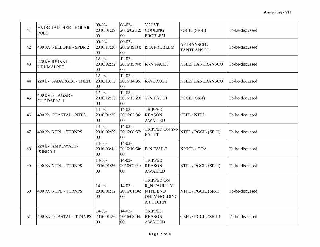
41HVDC TALCHER - KOLAR
POLE
08-03-
2016/01:29:
00
08-03-
2016/02:12:
00
VALVE
COOLING
PROBLEM
PGCIL (SR-II) To-be-discussed
42 400 Kv NELLORE - SPDR 2
09-03-
2016/17:20:
00
09-03-
2016/19:34:
00
ISO. PROBLEMAPTRANSCO /
TANTRANSCOTo-be-discussed
43220 kV IDUKKI -
UDUMALPET
12-03-
2016/02:32:
00
12-03-
2016/15:44:
00
R -N FAULT KSEB/ TANTRANSCO To-be-discussed
44 220 kV SABARGIRI - THENI
12-03-
2016/13:55:
00
12-03-
2016/14:35:
00
R-N FAULT KSEB/ TANTRANSCO To-be-discussed
45400 kV N'SAGAR -
CUDDAPPA 1
12-03-
2016/12:13:
00
12-03-
2016/13:23:
00
Y-N FAULT PGCIL (SR-I) To-be-discussed
46 400 Kv COASTAL - NTPL
14-03-
2016/01:36:
00
14-03-
2016/02:36:
00
TRIPPED
REASON
AWAITED
CEPL / NTPL To-be-discussed
47 400 Kv NTPL - TTRNPS
14-03-
2016/02:59:
00
14-03-
2016/08:57:
00
TRIPPED ON Y-N
FAULTNTPL / PGCIL (SR-II) To-be-discussed
48220 kV AMBEWADI -
PONDA 1
14-03-
2016/03:44:
00
14-03-
2016/10:50:
00
B-N FAULT KPTCL / GOA To-be-discussed
49 400 Kv NTPL - TTRNPS
14-03-
2016/01:36:
00
14-03-
2016/02:21:
00
TRIPPED
REASON
AWAITED
NTPL / PGCIL (SR-II) To-be-discussed
50 400 Kv NTPL - TTRNPS
14-03-
2016/01:12:
00
14-03-
2016/01:36:
00
TRIPPED ON
R_N FAULT AT
NTPL END
ONLY HOLDING
AT TTCRN
NTPL / PGCIL (SR-II) To-be-discussed
51 400 Kv COASTAL - TTRNPS
14-03-
2016/01:36:
00
14-03-
2016/03:04:
00
TRIPPED
REASON
AWAITED
CEPL / PGCIL (SR-II) To-be-discussed
Annexure- VII
Page 7 of 8

52 400 Kv COASTAL - NTPL
14-03-
2016/03:04:
00
14-03-
2016/20:28:
00
TRIPPED
REASON
AWAITED
CEPL / NTPL To-be-discussed
53220 kV AMBEWADI -
PONDA 1
14-03-
2016/03:44:
00
B-N FAULT KPTCL / GOA To-be-discussed
54 400 Kv NTPL - TTRNPS
14-03-
2016/02:59:
00
TRIPPED ON Y-N
FAULTNTPL / PGCIL (SR-II) To-be-discussed
55 400 Kv COASTAL - NTPL
14-03-
2016/03:04:
00
TRIPPED
REASON
AWAITED
CEPL / NTPL To-be-discussed
56 400 Kv NTPL - TTRNPS
14-03-
2016/01:36:
00
14-03-
2016/02:21:
00
TRIPPED
REASON
AWAITED
NTPL / PGCIL (SR-II) To-be-discussed
57 400 Kv NTPL - TTRNPS
14-03-
2016/01:12:
00
14-03-
2016/01:36:
00
TRIPPED ON
R_N FAULT AT
NTPL END
ONLY HOLDING
AT TTCRN
NTPL / PGCIL (SR-II) To-be-discussed
58 400 Kv COASTAL - NTPL
14-03-
2016/01:36:
00
14-03-
2016/02:36:
00
TRIPPED
REASON
AWAITED
CEPL / NTPL To-be-discussed
59 400 Kv COASTAL - TTRNPS
14-03-
2016/01:36:
00
14-03-
2016/03:04:
00
TRIPPED
REASON
AWAITED
CEPL / PGCIL (SR-II) To-be-discussed
60 400 Kv NTPL - TTRNPS
15-03-
2016/02:02:
00
15-03-
2016/03:51:
00
R -N FAULT NTPL / PGCIL (SR-II) To-be-discussed
61220 kV IDUKKI -
UDUMALPET
15-03-
2016/02:09:
00
15-03-
2016/02:51:
00
R-N FAULT KSEB/ TANTRANSCO To-be-discussed
Annexure- VII
Page 8 of 8
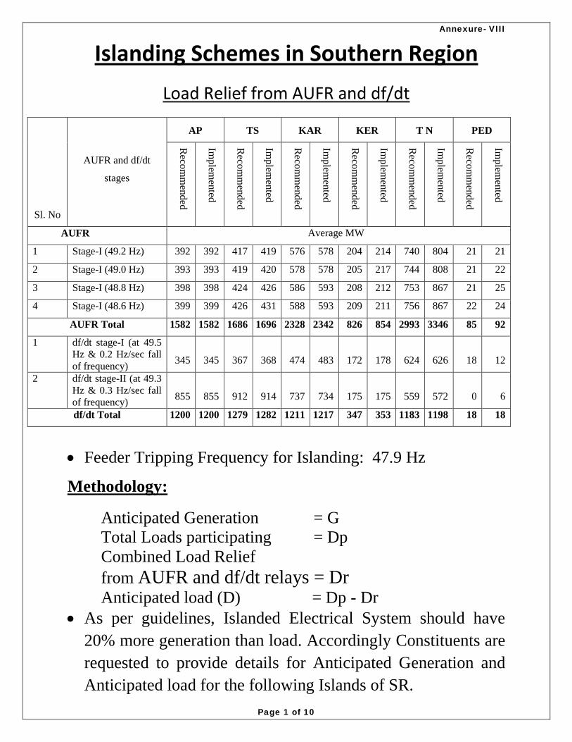
Islanding Schemes in Southern Region
Load Relief from AUFR and df/dt
Sl. No
AUFR and df/dt
stages
AP TS KAR KER T N PED
Reco
mm
end
ed
Implem
ented
Reco
mm
end
ed
Implem
ented
Reco
mm
end
ed
Implem
ented
Reco
mm
end
ed
Implem
ented
Reco
mm
end
ed
Implem
ented
Reco
mm
end
ed
Implem
ented
AUFR Average MW
1 Stage-I (49.2 Hz) 392 392 417 419 576 578 204 214 740 804 21 21
2 Stage-I (49.0 Hz) 393 393 419 420 578 578 205 217 744 808 21 22
3 Stage-I (48.8 Hz) 398 398 424 426 586 593 208 212 753 867 21 25
4 Stage-I (48.6 Hz) 399 399 426 431 588 593 209 211 756 867 22 24
AUFR Total 1582 1582 1686 1696 2328 2342 826 854 2993 3346 85 92
1 df/dt stage-I (at 49.5
Hz & 0.2 Hz/sec fall
of frequency) 345 345 367 368 474 483 172 178 624 626 18 12
2 df/dt stage-II (at 49.3
Hz & 0.3 Hz/sec fall
of frequency) 855 855 912 914 737 734 175 175 559 572 0 6
df/dt Total 1200 1200 1279 1282 1211 1217 347 353 1183 1198 18 18
Feeder Tripping Frequency for Islanding: 47.9 Hz
Methodology:
Anticipated Generation = G
Total Loads participating = Dp
Combined Load Relief
from AUFR and df/dt relays = Dr Anticipated load (D) = Dp - Dr
As per guidelines, Islanded Electrical System should have
20% more generation than load. Accordingly Constituents are
requested to provide details for Anticipated Generation and
Anticipated load for the following Islands of SR.
Annexure- VIII
Page 1 of 10

SRPC Secretariat| As on January, 2016 1
1. Hyderabad Islanding Scheme
Anticipated Generation 2896 MW
Total Loads Participating 3332.245 MW
AUFR+df/dt Load relief 200 MW
Anticipated Load 3132.2 MW
a) Generators Participating
S.No. Generator Entity
Anticipated MW
Supplying
1 ORIENT CEM 220.00 IPP 45
2 RGM-NTPC 400.00 RGM-TPS 187
3 RGM-NTPC 400.00 RGM-TPS 187
4 RGM-NTPC 400.00 RGM-TPS 187
5 RGM-NTPC 400.00 RGM-TPS 466
6 RGM-NTPC 400.00 RGM-TPS 466
7 RGM-NTPC 400.00 RGM-TPS 466
8 RGM-NTPC 400.00 RGM-TPS 471
9 KKTYATPS 400.00 TSGENCO 421
Anticipated Generation Total 2896
b) Loads Participating
Bus Number Load Entity Pload (MW)
422002 CHADRTTA 220.00 TS_STU 403.7675
422017 GACIBWLI 220.00 TS_STU 343.3528
422020 MOULALI 220.00 TS_STU 318.0552
422021 DURSHED 220.00 TS_STU 162.24
422024 MALKARAM 220.00 TS_STU 29.8391
422029 MEDCHAL 220.00 TS_STU 266.5906
422037 HIAL 220.00 TS_STU 54.466
422039 SIVRALLY 220.00 TS_STU 212.3238
422041 GAJWEL 220.00 TS_STU 177.0771
422044 PULKUTHY 220.00 TS_STU 15.1105
422053 SALIVAGU 220.00 TS_STU 6.9313
422055 BLMPLLI 220.00 TS_STU 138.4262
422063 SADASIVPET 220.00 TS_STU 129.8335
424002 RGM-NTPC 400.00 NTPC_SR 387.6287
422011 SHAURGAR 220.00 TS_STU 324.5029
Annexure- VIII
Page 2 of 10

SRPC Secretariat| As on January, 2016 2
422003 GHANAPUR 220.00 PGCIL_CTU 307.6458
422009 MALALLLI 220.00 TS_STU 54.4536
Total Loads participating 3332.245
AUFR Relief 200
df/dt Relief
Anticipated Load 3132.2
c) Feeders Tripping Sl.No Voltage
level
No. of
Circuit
From Bus Name To Bus Name
1 400 kV D/C Ramagundam Nagarjunasagar (Talapalli)
2 400 kV D/C Khammam Mamidapalli
3 400 kV D/C Malkaram VTPS- Stage-IV
4 400 kV D/C Ramagundam Bhadrawati
5 400 kV S/C Ghanapur Nagarjunasagar (Talapalli)
6 400 kV S/C Ghanapur Kurnool
7 400 kV S/C Shankarapalli Srisailam Left Bank
8 400 kV S/C Mamidapalli Srisailam Left Bank
9 400 kV S/C Ramagundam Dichipaly
10 400 kV S/C Khammam Warangal
11 220 kV S/C Kotagudem Shapurnagar
12 220 kV D/C Narketpalli Malkaram
13 220 kV D/C Dindi Chandrayengutta
14 220 kV S/C Malayalapalli Jagtiyal
15 220 kV D/C Malayalapalli Nagaram
16 220 kV D/C Warangal Nagaram
17 220 kV S/C Malayalapalli Bhimgal
18 220 kV S/C Malayalapalli Vemanoor
19 220 kV S/C Malayalapalli Medaram
20 220 kV S/C Shankarapalli Tandur
21 220 kV S/C Mamidapalli Shamshabad
22 220 kV S/C Mamidapalli Shadnagar
23 220 kV D/C Durshed Siddipet
24 220 kV D/C Gajwel Minipur
25 220 kV D/C Gajwel Kamareddy
26 220 kV D/C Yeddumailaram Shankarapalli
Annexure- VIII
Page 3 of 10

SRPC Secretariat| As on January, 2016 3
2. Chennai Islanding Scheme
Anticipated Generation 3484 MW
Total Loads Participating 4234.089 MW
AUFR+df/dt Load relief 620 MW
Anticipated Load 3614.089 MW
a) Generators Participating
S.No. Generator Entity
Anticipated
MW
Supplying
1 ETPS2 230.00 TN 30
2 MAPS2 230.00 MADRAS-APS 304
3 NCTPS-I 230.00 TN 594
4 SDEV 230.00 TN 10
5 OPG_ALM 230.00 TN 0
6 SUZLON 230.00 TN 0
7 KAMACHI 230.00 TN 5
8 KAVERI 230.00 TN 3
9 ARS 230.00 TN 3
10 VALLUR 400.00
NTECL-
VALLUR 1425
11 NCTPS-II 400.00 TN 1110
Anticipated Generation 3484
b) Load Participating
Bus Number Load Entity Pload (MW)
442001 TVALAM2 230.00 TN_STU 155.0332
442002 GUMDIP2 230.00 TN_STU 32.2072
442007 ACHARAP2 230.00 TN_STU 39.3613
442014 ARNI2 230.00 TN_STU 194.2737
442015 BASINBR2 230.00 TN_STU 87.9435
442021 ETPS2 230.00 TN_THERMAL 111.0315
442024 HYNDAI2 230.00 TN_STU 54.457
442027 KADAPEI2 230.00 TN_STU 202.5802
442034 KILPAWW2 230.00 TN_STU 133.2734
442037 KORATUR2 230.00 TN_STU 210.8154
442038 KOYMBDU2 230.00 TN_STU 239.1693
442043 MANALI2 230.00 TN_STU 135.3065
Annexure- VIII
Page 4 of 10
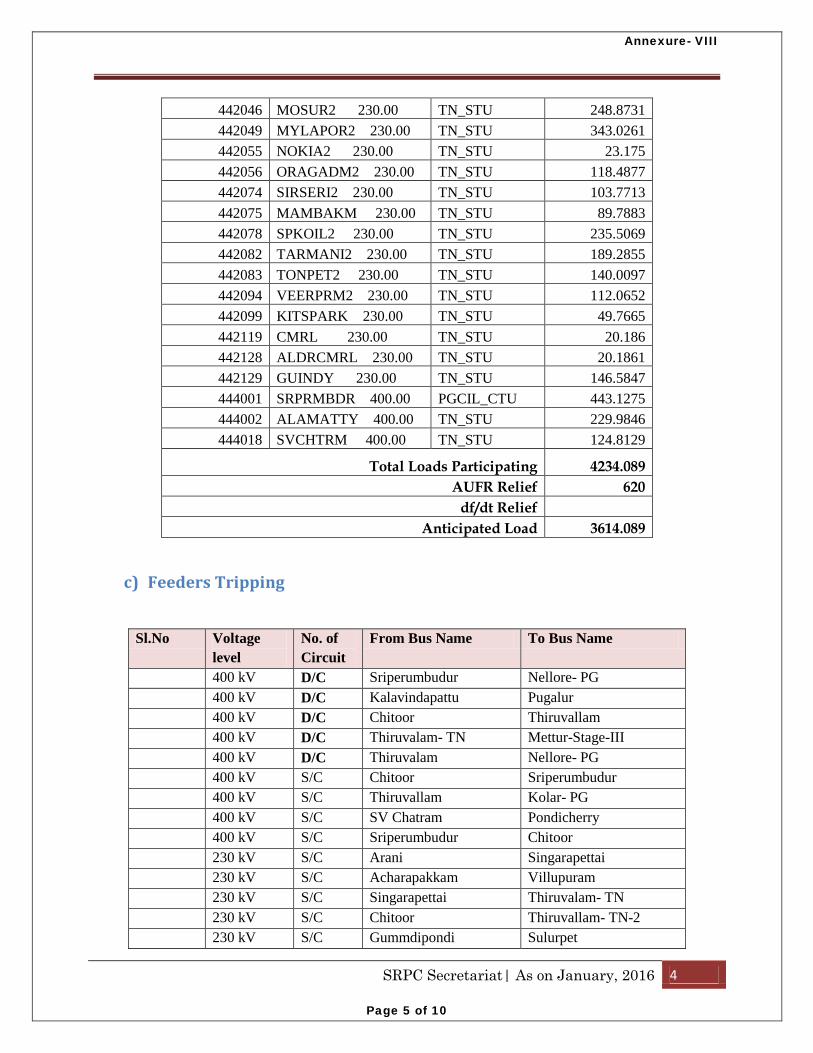
SRPC Secretariat| As on January, 2016 4
442046 MOSUR2 230.00 TN_STU 248.8731
442049 MYLAPOR2 230.00 TN_STU 343.0261
442055 NOKIA2 230.00 TN_STU 23.175
442056 ORAGADM2 230.00 TN_STU 118.4877
442074 SIRSERI2 230.00 TN_STU 103.7713
442075 MAMBAKM 230.00 TN_STU 89.7883
442078 SPKOIL2 230.00 TN_STU 235.5069
442082 TARMANI2 230.00 TN_STU 189.2855
442083 TONPET2 230.00 TN_STU 140.0097
442094 VEERPRM2 230.00 TN_STU 112.0652
442099 KITSPARK 230.00 TN_STU 49.7665
442119 CMRL 230.00 TN_STU 20.186
442128 ALDRCMRL 230.00 TN_STU 20.1861
442129 GUINDY 230.00 TN_STU 146.5847
444001 SRPRMBDR 400.00 PGCIL_CTU 443.1275
444002 ALAMATTY 400.00 TN_STU 229.9846
444018 SVCHTRM 400.00 TN_STU 124.8129
Total Loads Participating 4234.089
AUFR Relief 620
df/dt Relief Anticipated Load 3614.089
c) Feeders Tripping
Sl.No Voltage
level
No. of
Circuit
From Bus Name To Bus Name
400 kV D/C Sriperumbudur Nellore- PG
400 kV D/C Kalavindapattu Pugalur
400 kV D/C Chitoor Thiruvallam
400 kV D/C Thiruvalam- TN Mettur-Stage-III
400 kV D/C Thiruvalam Nellore- PG
400 kV S/C Chitoor Sriperumbudur
400 kV S/C Thiruvallam Kolar- PG
400 kV S/C SV Chatram Pondicherry
400 kV S/C Sriperumbudur Chitoor
230 kV S/C Arani Singarapettai
230 kV S/C Acharapakkam Villupuram
230 kV S/C Singarapettai Thiruvalam- TN
230 kV S/C Chitoor Thiruvallam- TN-2
230 kV S/C Gummdipondi Sulurpet
Annexure- VIII
Page 5 of 10

SRPC Secretariat| As on January, 2016 5
d) ICT Tripping Sl.No High Voltage (HV)
level
HV side- Bus Name Low Voltage (LV)
level
LV side- Bus
Name
1 765 kV Thiruvalam 400 kV Thiruvalam
2 765 kV Thiruvalam 400 kV Thiruvalam
3. Neyveli Islanding Scheme
Anticipated Generation 5285 MW
Total Loads Participating 5994.285 MW
AUFR+df/dt Load relief 2000 MW
Anticipated Load 3994.285MW
a) Generators Participating
S.No. Generator Entity
Anticipated
MW Supplying
1 Kadmparai TN 300
2 Kundah 2 TN 30.4
3 Kundah 3 TN 150
4 Kundah 4 TN 100
5 MTPS Stage-2 TN 792
6 MTRPH TN 0
7 STCMS TN 250
8 NLCTS12 230.00 TN 251.1
9 NLC22 230.00 NEYVELI-ALL 567
10 PP Nalur TN 0
11 PUSHEP TN 150
12 Suzlon TN 0
13 NLC1EXP 400.00 NEYVELI-ALL 384
14 NLC2 400.00 NEYVELI-ALL 756
15 NLC2EXP 400.00 NEYVELI-ALL 450
16 METR-III 400.00 TN 565
17 ILFS 400.00 ILFS 540
Anticipated Generation 5285.5
Annexure- VIII
Page 6 of 10

SRPC Secretariat| As on January, 2016 6
b) Loads Participating
Bus Number Load Entity Pload (MW)
442005 UDMLPT2 230.00 TN_STU 150.1811
442010 ALUNDR42 230.00 PGCIL_CTU 142.6378
442013 ARASUR2 230.00 TN_STU 389.5652
442017 CUDALRE2 230.00 TN_STU 165.7051
442018 DEVKRCY2 230.00 TN_STU 192.4078
442019 EACHNGA2 230.00 TN_STU 56.7152
442022 GOBI2 230.00 TN_STU 321.009
442025 INGUR2 230.00 TN_STU 401.9839
442026 KADALAN2 230.00 TN_STU 34.9428
442042 MTRAUTO 230.00 TN_STU 166.3279
442045 OKMNTPM 230.00 TN_STU 273.1627
442053 NLC22 230.00 TN_STU 125.49
442057 PALADAM2 230.00 TN_STU 260.6523
442060 PERMBLR2 230.00 TN_STU 241.6082
442061 PONPRM2 230.00 TN_STU 356.9801
442069 SALEM2 230.00 TN_STU 393.6232
442071 SAMAYPM2 230.00 TN_STU 129.861
442081 TANJORE2 230.00 TN_STU 180.993
442084 TRICHY2 230.00 TN_STU 280.4979
442088 TUDIYLR2 230.00 TN_STU 65.5438
442089 TVARUR2 230.00 TN_STU 40.98
442090 TVMALAI2 230.00 TN_STU 166.6578
442092 UNJANAI2 230.00 TN_STU 158.9933
442096 VILUPRM2 230.00 TN_STU 69.1459
442102 SDYPLYM 230.00 TN_STU 32.7086
442106 ANIKADVU 230.00 TN_STU 18.69
442107 ALIYAR 230.00 TN_STU 31.203
442126
PALKAPALYAM
230.00 TN_STU 90.8307
442127 ANTHIYUR 230.00 TN_STU 96.6601
444008 SALEM-TN 400.00 TN_STU 284.5355
452018 PALAKAD 220.00 KL_STU 272.6201
462002 VLIYANR2 230.00 PONDY_STU 204.5312
462003 BHAHUR2 230.00 PONDY_STU 196.8412
Total Loads Participating 5994.285
AUF Relief 2000
df/dt Relief Anticipated Load 3994.285
Annexure- VIII
Page 7 of 10

SRPC Secretariat| As on January, 2016 7
c) Feeders Tripping Sl.No Voltage
level
No. of
Circuit
From Bus Name To Bus Name
1 400 kV D/C Pugalur Kalavindapattu
2 400 kV D/C Myvadi Tirunelveli
3 400 kV D/C Salem Hosur
4 400 kV D/C Thiruvalam- TN Mettur-Stage-III
5 400 kV D/C Palakkad Thrissur
6 400 kV S/C Myvadi Checkanurani (Madurai)
7 400 kV S/C Alandur (Trichy) Checkanurani (Madurai)
8 400 kV S/C Alandur (Trichy) Karaikudi New
9 400 kV S/C Pugalur NLC Expansion 2
10 400 kV S/C Pugalur NLC TPS 2
11 400 kV S/C SV Chatram Pondicherry
12 230 kV S/C Acharapakkam Villupuram
13 230 kV S/C Alandur (Trichy) Alagarkoil
14 230 kV S/C Hosur Mettur Auto
15 230 kV S/C Karimangalam Mettur Auto
16 230kV S/C Pudanchandai Deviakurchi
17 230 kV S/C Pugalur Alandur (Trichy)
18 230 kV S/C Alandur (Trichy) Pudukottai
19 230 kV S/C Pugalur Myvadi
20 230 kV S/C Myvadi Sembatti
21 230 kV S/C Mettur TPS- 2 Singarapettai
22 230 kV S/C Singarapettai Salem
23 230 kV S/C Singarapettai TV Malai
24 230kV S/C Unjani Pudanchandai
25 230 kV S/C Thiruvarur Karambayam
26 230 kV S/C Udumalpet Idukki
27 230 kV D/C Palakkad (400 kVside) Madakathara
28 230 kV S/C Palakkad Madakathara
Annexure- VIII
Page 8 of 10

SRPC Secretariat| As on January, 2016 8
4. Koodankulam Islanding Scheme
Anticipated Generation 3620 MW
Total Loads Participating 3824.946 MW
AUFR+df/dt Load relief 800 MW
Anticipated Load 3024.946 MW
a) Generators Participating
S.No. Generators Entity PGen (MW)
1 INDARCPP 230.00 TN 0
2 TTPS2 230.00 TN 990
3 UDAYATR2 230.00 TN 0.4
4 STERLITE2 230.00 TN 6
5 IBPTL 2 230.00 TN 20
6 KKNPP 400.00 KKNPP 950
7 TUTCRNJV 400.00 NTPL 950
8 CENERGY 400.00 COASTL-ENERG 400
9 SABRGRI 220.00 KL 304
10 KAYMKLM 220.00 KL 0
Anticipated Generation 3620.4
b) Loads Participating
Bus Number Load Entity Pload (MW)
442006 THENI2 230.00 TN_STU 143.2453
442008 ALAGARK2 230.00 TN_STU 131.4524
442011 AMADPRM2 230.00 TN_STU 3.7718
442012 ANUPANG2 230.00 TN_STU 273.3405
442032 KARAIKD2 230.00 TN_STU 115.0001
442033 KAYTHAR2 230.00 TN_STU 45.7007
442036 KODIKUR2 230.00 TN_STU 75.8534
442058 PARMKDY2 230.00 TN_STU 96.864
442059 PASUMAL2 230.00 TN_STU 264.121
442063 PUDANS2 230.00 TN_STU 205.5551
442064 PUDUKOT2 230.00 TN_STU 160.8576
442066 PUGALUR2 230.00 TN_STU 249.8756
442068 RENGPRM2 230.00 TN_STU 145.601
442072 SANKNRI2 230.00 TN_STU 13.0247
442073 SEMBATY2 230.00 TN_STU 207.1181
442079 SRPUDUR2 230.00 TN_STU 129.2502
Annexure- VIII
Page 9 of 10

SRPC Secretariat| As on January, 2016 9
442085 TSIPCOT2 230.00 TN_STU 189.6917
442086 TTPAUTO2 230.00 TN_STU 128.5702
442093 VALTHUR2 230.00 TN_STU 75.167
442095 VERANAM2 230.00 TN_STU 3.7374
442108 KRMBYAM 230.00 TN_STU 24.9647
442130 TUTCRNJV 230.00 NTPL 20
444030 KAYATHAR 400.00 TN_STU 63.7883
452003 SABRGRI 220.00 KL_STU 0.382
452004 EDAMAN2 220.00 KL_STU 102.258
452004 EDAMAN2 220.00 KL_STU 114.0903
452007 EDAPAN 220.00 KL_STU 167.1125
452011 KUNDARA 220.00 KL_STU 160.4111
452020 POTHNCOD 220.00 KL_STU 399.0273
452033 PUNPRA 220.00 KL_STU 115.1144
Total Loads Participating 3824.946
AUFR relief 800
df/dt relief Anticipated Load 3024.946
c) Feeders Tripping Sl.No Voltage level No. of
Circuit
From Bus Name To Bus Name
1 400 kV D/C Pugalur Kalavindapattu
2 400 kV S/C Pugalur NLC Expansion 2
3 400 kV S/C Pugalur NLC TPS 2
4 400 kV S/C Alandur (Trichy) Checkanurani (Madurai)
5 400 kV S/C Alandur (Trichy) Karaikudi New
6 400 kV S/C Myvadi Checkanurani (Madurai)
7 400 kV D/C Myvadi Tirunelveli
8 230 kV S/C Pugalur Alandur (Trichy)
9 230 kV S/C Pugalur Myvadi
10 230 kV S/C Myvadi Sembatti
11 230 kV S/C Alandur (Trichy) Alagarkoil
12 230 kV S/C Alandur (Trichy) Pudukottai
13 230 kV S/C Thiruvarur Karambayam
14 230kV S/C Unjani Pudanchandai
15 230kV S/C Pudanchandai Deviakurchi
16 220 kV S/C Idukki New Pallom
17 220 kV S/C Sabarigiri Pallom
18 220 kV S/C Sabarigiri Ambalamugal
19 220 kV S/C Pallom New Pallom
Annexure- VIII
Page 10 of 10

Load Impedance
Encroachment
&
Over Current Protection
Settings
Annexure- IX
Page 1 of 15

2
Power flow on a Transmission line
Annexure- IX
Page 2 of 15

3
Annexure- IX
Page 3 of 15

4
Distance Relay characteristics modified for Load Encroachment
Annexure- IX
Page 4 of 15

5
Ideal solution to tackle load encroachment may
be based on the use of blinders or by suitably
setting the resistive reach of specially shaped
impedance elements or by use of polygon type
impedance elements.
It is recommended that all the distance relays
should have quadrilateral / polygon characteristic.
For relays having Mho characteristics, it is
desirable to have load encroachment prevention
characteristics or a blinder.
Annexure- IX
Page 5 of 15

6
In the absence of credible data regarding minimum voltage and maximum load expected for a feeder during emergency system condition, following criteria may be considered for deciding resistive reach / blinder setting to prevent load point encroachment: Maximum load current (Imax) may be considered as
1.5 times the thermal rating of the line or 1.5 times the associated bay equipment current rating ( the minimum of the bay equipment individual rating) whichever is lower. (Note: The rating considered is approximately 15 minutes rating of the transmission facility). Minimum Voltage (Vmin) to be considered as 0.85pu
(85%). For setting angle for load blinder, a value of 30 degree
may be adequate in most cases.
Annexure- IX
Page 6 of 15

7
For high resistive earth fault where impedance locus
lies in the Blinder zone, fault clearance shall be
provided by the back-up directional earth fault relay.
Load encroachment feature is to be enabled in
distance relays where the zone-3 resistive reach is
more than the load resistance.
Annexure- IX
Page 7 of 15

8
Annexure- IX
Page 8 of 15

9
Directional Phase Over Current Protection (TL):
Directional phase over current relays are still being
used as back-up protection for 220kV transmission
lines by many utilities. However, in view of time
coordination issues and increased fault clearance time
in the event of failure of main distance protection, it
is recommended that for all 220kV lines also main-1
and main-2 protections similar to 400kV lines be
provided.
In these relays, it is desirable to set the pickup value
around ~ 120 % I(base) [based on the Emergency
rating of conductor].
Annexure- IX
Page 9 of 15

10
Directional Ground Over Current Protection (TL) The ground over current threshold should be set to
ensure detection of all ground faults, but above any continuous residual current under normal system operation. Continuous residual current may arise because of following: Unbalanced series impedances of untransposed
transmission circuits
Unbalanced shunt capacitance of transmission circuits.
Third harmonic current circulation.
In these relays, it is desirable to set the pickup value around 20 % I(base).
Annexure- IX
Page 10 of 15

11
Phase Over Current Protection (ICTs):
The phase over current threshold should be set to
ensure detection of all phase faults, but above any
continuous phase current under normal system
operation. The timing should be coordinated with the
phase over current protection of downstream network.
The non-directional Instantaneous high set over
current element shall be set to a value which is 1.3
times the transformer through fault current or transformer inrush current, whichever is higher.
Annexure- IX
Page 11 of 15

12
Model Setting Calculations: • I1>: This parameter is set to 150% of base current.
• k1 (TMS): Model value is 0.26.
• I2>: This parameter is set to 800% of base current.
• t2: This parameter is set to 0.05s.
Over Load Protection:
Overload relay shall be set at 105% of rated current with
delay of 5 seconds. This shall be connected to give only
alarm and not for tripping. The Alarm is used to alert the
operator to take necessary steps to reduce loading.
In the event of sudden increase in load current, the
mechanical protections like Oil temperature high and
Winding temperature high should take care of this.
Annexure- IX
Page 12 of 15

13
Directional Ground Over Current Protection (ICTs):
The ground over current threshold should be set to
ensure detection of all ground faults, but above any
continuous residual current under normal system
operation. The timing should be coordinated with the
downstream backup protection including Zone-3
timing for a remote end 220kV bus fault.
Setting Calculations:
• IN1>: This parameter is set to 20% of base current.
• k1 (TMS): Model value is 0.58.
• IN2>: This parameter is set to 800% of base current.
• t2: This parameter is set to 0.05s.
Annexure- IX
Page 13 of 15

14
Report of the Task Force on Power System under Contingencies (August, 2013)
Model Setting Calculations for Typical IEDs, Line Protection Setting Guidelines, Protection System Audit Check-list, Recommendations for Protection Management. (March, 2014)
CBIP Publication no 274: Manual on Protection of Generators, Generator Transformers and 220kV and 400kV Networks
CBIP Publication no 296: Manual on Reliable Fault Clearance and Back-Up Protection of EHV and UHV Transmission Networks
CIGRE WG B5.10, 411: Protection, Control and Monitoring Of Series Compensated Networks
CIGRE WG 34.04 ; Application Guide on Protection Of Complex Transmission Network Configurations
Annexure- IX
Page 14 of 15

15
Annexure- IX
Page 15 of 15

This is a special report of the IEEE – Power System Relay Committee.
March 2001
TRANSMISSION LINE
PROTECTIVE SYSTEMS LOADABILITY
A report to the
Power System Relay Committee of
the IEEE Power Engineering Society
prepared by working group D6
Abstract
This paper is about the effects of protective relaying on the loadability of transmission lines. The calculation of
relaying load limits for use in comparing to transmission line load limits or other limits is discussed. The identification
of problems associated with the application of relay protection that result in the interference of line loading capabilities
is covered. This is followed by the discussion of methods available that are aimed at increasing the loadability of relay
schemes while also maintaining required levels of relay coverage and security.
Members of the working group
Tony Seegers - chair Ed Krizauskas - vice-chair
Mike Agudo Larry Budler
Doug Dawson Tom Domin
Daniel Hamai Charlie Henville
Bob Holmgren Dave Jamison
Bogdan Kasztenny Peter Kotos
Bill Lowe Bernard Matta
Mike McDonald Dean Miller
George Moskos Brad Nelson
Don Sevcik Tarlochan Sidhu
Skip Williams Karl Zimmerman
John Zipp
Annexure- X
Page 1 of 30

This is a special report of the IEEE – Power System Relay Committee.
Page i March 2001
Contents
1. Introduction …………………………………………………………………………. 1
2. Fundamental Concepts of Loadability …………………………………………….. 1
2.1 Definition of Relay Load Limit …………………………………………….. 1
2.2 Calculation of Load Limits …………………………………………….. 1
2.2.1 Overcurrent Relays …………………………………………….. 1
2.2.2 Distance Relays …………………………………………….. 2
2.2.3 Current Differential Relays …………………………………… 3
2.2.4 Phase Comparison Relays …………………………………… 4
3. Factors Affecting Line Loadability …………………………………………….. 4
3.1 Protective Equipment …………..………………………………………….. 4
3.1.1 Relays ………..…………………………………………….. 4
3.1.2 Pilot Systems ………..…………………………………………….. 7
3.1.3 Current Transformers …………………………………………..… 7
3.2 System Factors ……………………………………………………… 7
3.2.1 Transmission Line Ratings ……………………………………………. 7
3.2.2 Transmission System Power Factor …………………………. 10
3.2.3 Unbalanced Currents …………………………………………….. 11
3.2.4 Multi-Terminal Lines …………………………………………….. 11
3.2.5 Power Swings …………………………………………….. 12
3.2.6 Faults and Fault Angles …………………………………………….. 13
4. Solutions ………………………………………………………………………... 14
4.1 Relay Settings ………..…………………………………………….. 14
4.1.1 Line Coverage …………………………………………….. 14
4.1.2 Backup Coverage …………………………………………….. 15
4.1.3 Breaker Failure …………………………………………..… 16
4.2 Dealing with Transients ……………………………………………. 16
4.2.1 Voltage ………..……………………………………………. 16
4.2.2 Thermal Load ………..……………………………………………. 17
4.2.3 Load Angle ………..……………………………………………. 17
4.2.4 Outages ………..……………………………………………. 18
4.3 Protective Equipment ………..……………………………………………. 18
4.3.1 Distance Relay Characteristic Shape …………………………. 18
4.3.2 Use of blinders ……………………………………………. 18
4.3.3 Power Swing Blocking ……………………………………………. 19
4.3.4 Adaptive techniques ……………………………………………. 20
4.4 Systems ……………………………………………………………. 20
4.4.1 Planning ………..………….……………………………….… 20
4.4.2 Controlled Flows on Lines …………………………………... 20
4.4.3 Load Shedding ……………………………………………. 20
4.4.4 Series-Compensated Lines …………………………………... 20
5. Summary ………………………………………………………………………… 22
6. Appendix ………………………………………………………………………… 23
Appendix A: Overcurrent Relay Loadability Calculation Example. ……… 23
Mho Distance Relay Loadability Calculation Examples ……… 23
Appendix B: Fundamentals of Distance Relays …………………………. 24
7. References ………………………………………………………………………… 29
8. Bibliography ………………………………………………………………………… 29
Annexure- X
Page 2 of 30

This is a special report of the IEEE – Power System Relay Committee
Page 1 March 2001
February 2001
1. Introduction
As transmission lines are loaded to higher and higher levels, and as the concept of open transmission access becomes
a reality, the subject of load-carrying capabilities of transmission lines is becoming increasingly important. Short term
ratings of lines are being applied for system operations, and conflicts with load limitations and the protection system
settings are becoming more prevalent.
Generally, the characteristics of the line itself should determine the limits of line loading. The level to which the
protection system permits a transmission line to be loaded is based on transmission line protection design and setting
philosophies, system characteristics, and protective equipment thermal ratings. A line relay load limit is established
for the purpose of comparing with the line load limit to determine if steps must be taken to prevent undesirable relay
operation.
This paper discusses the various factors to consider concerning relays in the determination of transmission line
loadability; considerations for protection design and relay setting philosophies to prevent limitations on line
loadability; and utility practices for settings, equipment ratings, and methods to mitigate related problems.
2. Fundamental Concepts of Loadability
2.1 Definition of Relay Load Limit
For the purposes of this document, the line relay load limit will be defined to be the loading permitted by the relay
including a security margin. The direction of power flow may or may not be a factor depending on the relay
2.2 Calculation of Load Limits
Protective relay load limits are often conservative, with some room provided for equipment errors and some
fluctuation in the loading. The amount of these margins is dependent upon the amount of risk of load induced
protection trips the user is willing to accept. Therefore when calculating load limits, it is wise to recognize the role that
margins play, and to clearly state whether or not the calculated limits include any margins. The following discussion
on calculation will include consideration of margins.
2.2.1 Overcurrent Relays
These relays respond to a specific value of current which can be converted to a specific load by multiplying by the
operating voltage. However, since current magnitude is sometimes available to operators, it is better to state the load
limit in terms of current. The current load limit is the magnitude of current at which the relay is expected to start
timing towards its trip condition. When considering this limit, it is important to be aware of two factors:
a) The overcurrent relays, line current monitors, and the interposing transducers exhibit finite accuracy.
Therefore it is possible that the relay may operate at a current lower than the set current or the monitored current.
b) The load current may sometimes remain considerably above the steady state level for an amount of time
in excess of the relay operating time. The usual cause of sustained high load currents is cold load pickup, when load
currents may remain at 50% to 100% higher than the steady state value. Overcurrent relays are typically applied on
subtransmission lines that are more susceptible to cold load pickup conditions than transmission lines.
When the above two factors are considered it is clear that the load current limit should include a safety margin. A
margin of 10 to 20 percent is typical if cold load pickup is not a factor. A higher margin is more appropriate if cold
load pickup is a possibility. The trip point load limit (without margin) of an overcurrent relay set to trip at a current I
Annexure- X
Page 3 of 30

This is a special report of the IEEE – Power System Relay Committee
Page 2 March 2001
February 2001
(in amperes), can be expressed in terms of “Trip Point Amps” or as “Trip Point MVA” at a given line to line voltage
VLL (in volts). These values can be calculated by:
Smax = √3 * VLL * I where all values are physical units (1)
Appendix A gives an example of a loadability calculation for a transmission line overcurrent relay.
2.2.2 Distance Relays
These relays respond to an impedance of varying magnitude which depends on the power factor of the load
impedance. Their load limit is normally quoted in MVA, at nominal operating voltage at some specified power factor.
This point is chosen to be conservative enough to exceed expectations of actual line load levels and power factors. The
distance relay definite time delays are usually much faster than those of overcurrent relays; so margins have to allow
for larger transient conditions (with shorter duration) than is the case with overcurrent relays. On the positive side,
since these relays are usually applied on transmission lines which are not exposed to the cold load pickup
phenomenon, such load pickup is not usually a concern.
The most commonly encountered distance characteristic is the mho. Other distance relay characteristics will exhibit
different responses to loading and may be more or less appropriate for use in situations where loading is a problem.
(See Appendix B)
Figure 1 shows the apparent impedance of the load with respect to a distance relay with a forward reaching mho
characteristic.
R
NO TRIP
OUTSIDE
OF CIRCLE
X
q
ZR
ZL
Steady State
Loadability Limit
A pparent steady state
load impedance
in this region
X
f
Figure 1: Loadability calculation for mho characteristic
Annexure- X
Page 4 of 30
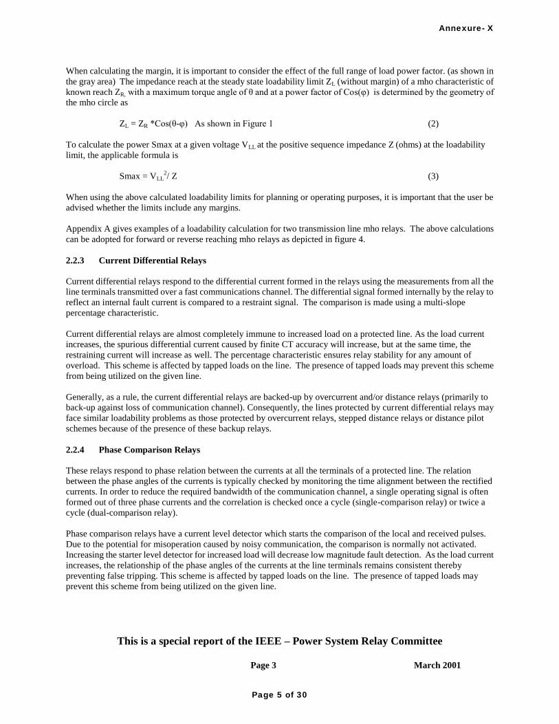
This is a special report of the IEEE – Power System Relay Committee
Page 3 March 2001
February 2001
When calculating the margin, it is important to consider the effect of the full range of load power factor. (as shown in
the gray area) The impedance reach at the steady state loadability limit ZL (without margin) of a mho characteristic of
known reach ZR, with a maximum torque angle of θ and at a power factor of Cos(φ) is determined by the geometry of
the mho circle as
ZL = ZR *Cos(θ-φ) As shown in Figure 1 (2)
To calculate the power Smax at a given voltage VLL at the positive sequence impedance Z (ohms) at the loadability
limit, the applicable formula is
Smax = VLL2/ Z (3)
When using the above calculated loadability limits for planning or operating purposes, it is important that the user be
advised whether the limits include any margins.
Appendix A gives examples of a loadability calculation for two transmission line mho relays. The above calculations
can be adopted for forward or reverse reaching mho relays as depicted in figure 4.
2.2.3 Current Differential Relays
Current differential relays respond to the differential current formed in the relays using the measurements from all the
line terminals transmitted over a fast communications channel. The differential signal formed internally by the relay to
reflect an internal fault current is compared to a restraint signal. The comparison is made using a multi-slope
percentage characteristic.
Current differential relays are almost completely immune to increased load on a protected line. As the load current
increases, the spurious differential current caused by finite CT accuracy will increase, but at the same time, the
restraining current will increase as well. The percentage characteristic ensures relay stability for any amount of
overload. This scheme is affected by tapped loads on the line. The presence of tapped loads may prevent this scheme
from being utilized on the given line.
Generally, as a rule, the current differential relays are backed-up by overcurrent and/or distance relays (primarily to
back-up against loss of communication channel). Consequently, the lines protected by current differential relays may
face similar loadability problems as those protected by overcurrent relays, stepped distance relays or distance pilot
schemes because of the presence of these backup relays.
2.2.4 Phase Comparison Relays
These relays respond to phase relation between the currents at all the terminals of a protected line. The relation
between the phase angles of the currents is typically checked by monitoring the time alignment between the rectified
currents. In order to reduce the required bandwidth of the communication channel, a single operating signal is often
formed out of three phase currents and the correlation is checked once a cycle (single-comparison relay) or twice a
cycle (dual-comparison relay).
Phase comparison relays have a current level detector which starts the comparison of the local and received pulses.
Due to the potential for misoperation caused by noisy communication, the comparison is normally not activated.
Increasing the starter level detector for increased load will decrease low magnitude fault detection. As the load current
increases, the relationship of the phase angles of the currents at the line terminals remains consistent thereby
preventing false tripping. This scheme is affected by tapped loads on the line. The presence of tapped loads may
prevent this scheme from being utilized on the given line.
Annexure- X
Page 5 of 30

This is a special report of the IEEE – Power System Relay Committee
Page 4 March 2001
February 2001
Like the current differential relays, the phase comparison relays are often backed-up by overcurrent and/or distance
relays (to cover loss of communication channel). As a consequence, the lines protected by phase comparison relays
may face certain loadability problems because of the presence of these backup relays.
3. Factors Affecting Line Loadability
3.1 Protective Equipment
When determining the loadability of a transmission line, the limitations due to the protective equipment must be
considered.
3.1.1 Relays
Published relay characteristics are based on the operation of relays within specified limits of environmental conditions
and electrical inputs. The accuracy and sensitivity of relays change (generally decrease) when the relays are operated
outside of the specified limits.
3.1.1.1 Relay Ratings
The ANSI/IEEE C37.90 standard [1] specifies standard service conditions, standard ratings, performance
requirements, and requirements for testing of relays and relay systems used to protect and control power apparatus.
With regard to loadability, the following pertinent ratings should be considered: the standard current and voltage
ratings, maximum design current and voltage at which the relay is designed to be energized continuously, and the total
temperature of relay coils which is the sum of the temperature rise of coils and the ambient temperature.
The effect of higher currents, voltages, and ambient temperature is to increase the total temperature inside the relay.
Higher relay temperatures reduce relay insulation life. Also, the sensitivity and accuracy of the relay most likely will
be decreased. Therefore, from a thermal point of view, if the sensitivity, accuracy, and service life of the relay is to be
preserved, the continuous load current should not exceed the maximum design current at which the relay can be
energized continuously.
If the average ambient temperature in a given installation exceeds the rated ambient temperature, then the continuous
currents and voltages applied to the relay need to be derated to avoid the thermal consequences mentioned above.
3.1.1.2 Overcurrent Relays
The aforementioned standard [1] specifies the standard current ratings, but does not specify the highest current at
which the relay can be energized continuously. Through the years, relays have been designed to meet or exceed the
standard current ratings. Consequently, the margin by which the maximum continuous current exceeds the standard
current rating varies from relay to relay and manufacturer to manufacturer. Typical values of maximum continuous
currents for overcurrent relays are usually 2-3 times nominal tap current. If overcurrent relays are connected to trip,
they usually cannot be subjected to steady state currents greater than their pickup tap setting (because the relay will trip
the circuit shortly after the current exceeds the pickup tap setting). Thus their maximum continuous rating is not
usually a factor in limiting line loadability, unless their tripping function has been disabled to allow more load carrying
capability.
3.1.1.3 Distance Relays
Distance relays are energized by VT voltages and CT currents. The standard voltage ratings, maximum continuous
voltages, and standard current ratings for the relays are specified by the above standard. The maximum continuous
Annexure- X
Page 6 of 30

This is a special report of the IEEE – Power System Relay Committee
Page 5 March 2001
February 2001
current is not specified and it varies from relay to relay. Typical values of maximum continuous currents for distance
relays are usually 2-3 times rated nominal current.
The load limit for distance relays is covered in clause 2 “Fundamental Concepts of Loadability”.
3.1.1.4 Directional Power
Directional power relays can be applied on intertie lines between utilities, or between a utility and non-utility
generation. These relays measure voltage and current and then calculate real power (watts), usually to limit power
transfer due to line thermal limitations or commercial purposes. The basis for the setting of the relay becomes the load
limit for the line.
3.1.1.5 Thermal Replica
Thermal replica relays emulate as closely as possible thermal processes in a protected system element. Practically,
they are implemented exclusively as microprocessor-based relays utilizing currents, a temperature probe input, and a
thermal and physical model of the transmission line aimed at calculating the hottest spot temperature based on
available data in order to cause alarms or to trip. This type of relay uses current magnitude, and may also use other
parameters such as the physical properties of the conductor, the effects of solar heating, the estimated wind speed
across the conductor, geographical location (longitude and latitude), ambient temperature (measured), date, and time
of day. Since the velocity and the direction of the air flow in the proximity of the line has a significant effect on the
temperature of the conductors and due to the potential for variation of these factors along the line; several critically
located sensors would be needed. In the absence of these sensors and the communication system needed to
consolidate that data from the sensors, assumptions must be made and margins used to allow for the errors in those
assumptions.
3.1.1.6 Fault Detectors
Fault detectors refer to instantaneous overcurrent relays (usually non-directional) that supervise the operation of
distance relays. In electromechanical schemes, the pick up of the fault detectors should be set above load to prevent
contact wear due to chatter when the current is near pickup. Fault detectors can be set below load for multifunction
microprocessor relay applications.
Some complex relays use the trip-supervising fault detectors to also serve as the fault detectors for the
switch-onto-fault (SOTF) protection. When closing a breaker into heavy line loads, this can cause false (SOTF) trips
if the fault detectors were set low enough to pick up. In this case, SOTF should be supervised by additional logic, such
as undervoltage, to prevent false operation upon picking up load.
Some fault detectors used in microprocessor-based relays utilize the zero- and negative-sequence currents, sense the
incremental positive sequence current (increase with respect to certain historical values), as well as adjust the
threshold for the absolute current levels using an adaptive slow-acting control loop. Such improved fault detectors
used to supervise the distance elements may prevent some false operations due to heavy loading.
3.1.1.7 Remote Breaker Failure Backup
At times, the protective relays on a line may be set to provide backup protection to lines leaving the remote bus. The
increased relay reach required to provide this coverage will reduce the loading permitted by the relays. The
installation of breaker failure and secondary relaying on those remote line terminals may reduce the need for remote
backup allowing for shortened relay reaches and greater load capability on the line.
3.1.1.8 Local Backup Relaying
Annexure- X
Page 7 of 30
This is a special report of the IEEE – Power System Relay Committee
Page 6 March 2001
February 2001
Local backup may be viewed as a secondary relaying system that provides backup for a failure of the primary relaying
system. This secondary system typically is set identical to the primary so load limits are not affected unless the
secondary relay has a characteristic that is more susceptible to tripping on load. This system does not cover the failure
of a local interrupting device.
Another form of local backup is the protection for a failure of the local breaker or for a failure of the complete relay
system. Also, as mentioned in the previous clause, local breaker failure relaying provides a means to isolate the fault
„locally‟ thereby reducing the need for a long reaching (and possibly load limiting) remote backup relaying settings.
The fault-detecting relay that is used in the local breaker failure scheme is normally not the load limiting device.
3.1.1.9 Overload Protection of Tie Lines
Unscheduled outages can be a problem with major intertie transmission lines. When such a line is removed from
service by fault or otherwise, the power flow through the rest of the system will likely persist. It is at such a time that
overload conditions on other tie lines and internal lines could occur.
Occasionally overcurrent relays are used to protect tie lines from overloading. When power flows increase drastically,
overload relays can help prevent damage to transmission lines and other equipment. The overcurrent relay
characteristics have to be based on both time and current to prevent false tripping due to short term transient load
excursions. The overload relays must carry maximum load during short time or emergency conditions, without
tripping.
It is not always the line on which the overload relays are installed that could be damaged. Shedding tie line load may
prevent overloading of other transmission lines and equipment in the system. Occasionally the overload sensing of a
transmission tie line is used to transfer trip a transmission line or other equipment in some other part of a system, and
vice versa.
3.1.2 Pilot Systems
Line loading can cause a problem for a specific case of blocking carrier. In a directional comparison blocking scheme
on a three-terminal line, outgoing load can pick up the reverse zone relay on one terminal, thereby sending carrier to
block the other two terminals. If that terminal with outgoing load is a weak fault current source, a fault on the
protected line may not drop out the picked-up blocking. In that case, the other two terminals of the line would remain
blocked and will not pilot trip for the fault.
In phase comparison blocking schemes, current-based fault detectors key carrier at one current level and arm the
comparison tripping logic at a higher current level. Sufficient load to key carrier, but not arm tripping, will not present
a tripping risk, but will operate the carrier and may bring in alarms for sustained carrier keying. Load through the line
(appearing like an external fault) above the comparison tripping level presents a risk of false trip if the blocking carrier
function does not perform correctly each half cycle. This applies to two or three-terminal lines.
3.1.3 Current Transformers
3.1.3.1 Thermal Limits
The CT ratio should be selected so that, for maximum primary load current the secondary current produced does not
exceed the continuous thermal current rating of any part of the CT overall secondary circuit. Most CTs have a nominal
continuous current rating of 1- or 5- secondary amperes, but higher ratings can be specified. These ratings are
specified by the standard rating factor. Values of the standard rating factor are 1.0, 1.33, 1.5, 2.0, 3.0 and 4.0 [2].
Cables and wire leads will usually have a greater ampacity than the CT secondary because other considerations
determine cable and wire size.
Annexure- X
Page 8 of 30

This is a special report of the IEEE – Power System Relay Committee
Page 7 March 2001
February 2001
3.1.3.2 Error
Maximum CT ratio error occurs during fault current, not load current, so CT ratio error is not a significant issue in
affecting loadability. However, some low ratio protection CTs may have errors of a few percent even at load currents.
CT accuracy will not be an issue if load limiting relays and meters are connected to the same CTs. However, if the
relays are connected to high accuracy CTs and the meters are connected to low accuracy CTs, the relays may "see"
currents a few percent higher than the meters. In such cases, lines operating close to load limits of relays may actually
be operating somewhat closer to the relay limits than indicated by the meters. The effects of such CT errors along with
other metering errors should be accommodated in the margins discussed in Clause 2.2 of this paper.
3.2 System Factors
3.2.1 Transmission Line Ratings
In the current market environment, utilities are pressured to use the capability of their transmission lines to the fullest
extent by taking advantage of short term ratings, less conservative assumptions, and dynamic ratings. Relays and their
associated settings should be applied with both objectives of protecting the transmission line and making available the
full capacity of the line.
Ratings of overhead transmission lines depend on the maximum temperature which the associated conductors may
reach without exceeding clearance or conductor thermal damage limits. When an increase in current flow occurs on a
conductor, its temperature change follows a time curve determined by the amount of current change, ambient
conditions, and properties of the conductor. Ambient conditions include wind speed, air temperature, amount of cloud
cover, angle of sun in the sky, and various other parameters of the surrounding air.
3.2.1.1 Continuous Rating
In Figure 2, I1 and Temp 1 represent less than critical flow, with a dynamic change to I2 and Temp 2 at critical flow. If
Temp 2 represents the limiting or „critical‟ temperature for which a line is designed, then I2 would represent the
continuous rating of the line and could flow indefinitely. This rating is sometimes referred to as the „normal‟ or „24
hour‟ rating. Line ratings are typically expressed in amperes or MVA.
T ime
Tem
pera
ture
Curr
ent
I1
I2
T ime
Temp 1
Temp 2
Time1
Time2
Time1
Time2
Figure 2: Critical temperature rise for the continuous rating of a line
3.2.1.2 Short Term Rating
Annexure- X
Page 9 of 30

This is a special report of the IEEE – Power System Relay Committee
Page 8 March 2001
February 2001
When the current increases are of short duration, a higher current level can exist without exceeding the critical
temperature limit. A typical „short-term‟ temperature rise characteristic is illustrated in Figure 3. Short term or
„emergency‟ ratings of lines are established to identify the level of overload that can be carried by transmission lines
during short time frames which typically vary from several minutes to several hours.
Time
Te
mp
era
ture
Curr
ent
I1
I2
Time
Temp 1
Temp 2
Time1
Time2
Time1
Time2
Figure 3: Typical temperature rise for determining short term ratings
3.2.1.3 Seasonal Ratings
Since the conductor temperature rise is dependent on ambient temperature, different ratings can be established from a
seasonal standpoint on the basis of expected ambient temperatures using probabilistic historic data. Summer and
winter ratings are typically established. In the same way, day and night ratings can also be developed.
3.2.1.4 Dynamic Ratings
The above rating methods are static in nature and are embedded with conservative assumptions to allow for „worst
case‟ conditions. Dynamic ratings are based on actual prevailing conditions as they exist at a given time and, as such,
are typically higher than related static ratings. Determination of line ratings on a dynamic basis requires real time
continuous monitoring of parameters such as conductor temperature or line tension.
It is possible that static ratings of other equipment connected in series with a line such as circuit breakers, switches and
line traps may be less than that of the line itself. In such cases, the facility with the lowest rating will determine the
maximum load that can be applied to the line.
Annexure- X
Page 10 of 30

This is a special report of the IEEE – Power System Relay Committee
Page 9 March 2001
February 2001
R
high load
low load
X q
f
trip point
POWER FLOWS OUT
POWER FLOWS OUTPOWER FLOWS IN
POWER FLOWS IN
VARS FLOW OUTVARS FLOW OUT
VARS FLOW INVARS FLOW IN
Q-II Q-I
Q-III Q-IV
Figure 4: Load vs. trip point on R-X diagram
3.2.2 Transmission System Power Factor
Load is practically viewed as MW and Mvars, which can be converted to impedance and plotted as a point on an R-X
diagram as shown in Figure 4. The shaded areas show typical load regions. Lines can be operated with the apparent
load impedance in any of the four quadrants of the R-X plane. (e.g. Quadrant I: REAL POWER FLOWS OUT, VARS
FLOW OUT) As load increases, the apparent impedance decreases, thereby moving the load impedance point toward
the origin, and closer to the mho circle trip characteristic.
The angle of the load current (power factor angle) determines the angular location of the load impedance point and at
what angle φ it would contact the mho trip circle. Power factor (PF) angles typically range from zero degrees to +/- 40
degrees, compared to the relay characteristic impedance angle θ which typically ranges from 60 to 80 degrees. As
shown in Figure 4, the power factor angle affects the loadability. For example, in Quadrant I (POWER FLOWS OUT,
VARS FLOW OUT), as the PF angle increases, the load which can be transferred decreases. One must also be aware
of load in the reverse direction (Quadrants II and III).
For long reaching mho settings, some utilities assume the worst case of the load angle equal to the relay angle. Others
take advantage of a more reasonable assumption such as 32°, 30° or 26° lagging load. For example, this can provide as
Annexure- X
Page 11 of 30

This is a special report of the IEEE – Power System Relay Committee
Page 10 March 2001
February 2001
much as 37%, 41% or 52% increased loadability, respectively, compared to using a relay angle of 75 degrees as the
load angle.
3.2.3 Unbalanced Currents
Unbalanced load currents present additional challenges to transmission line protection systems. If one phase is more
heavily loaded than the others, the relay load limit on that phase (due to overcurrent, impedance or mho relay limits)
will result in a lower three phase load than could have been transmitted if all three phases were balanced. Unbalanced
load current also results in zero sequence or negative sequence currents that may appear as faults to sensitive
protection that responds to such quantities. It should be noted that even though the load presented to a transmission
system may be balanced, unbalances in the system impedances may result in unbalanced load currents. Unbalanced
system impedances are most often caused by untransposed transmission lines. The unbalanced currents resulting from
such unbalanced impedances generally become more of a problem as loads become very heavy or if unbalanced
settings are too sensitive.
Most conventional fault study and power flow analysis computer programs usually assume the power system is
completely balanced. Special analytical tools are required to represent the system on a phase by phase basis to
examine the effect of load and system unbalances. Such tools include electromagnetic transients programs (that
perform steady state analysis on a phase by phase basis), and specially written analytical routines on commercial
graphic analysis/mathematical programs. These special tools are not normally used on conventional protective relay
applications. Therefore the first indicator of a load balance problem affecting line loadability is usually undesirable
line tripping during heavy loads. Digital relay event records that include pre-trip recordings will assist in the
identification of such unbalances. Multifunction digital relays may also have spare unbalance current level detectors
that could be used to generate an alarm if sustained unbalanced load current approach the limits of unbalance
protection. These alarms may be used to identify approaching load limits due to unbalance before the limit is found by
line tripping.
One solution to the potential misoperation of neutral and negative-sequence overcurrent relays under overload
unbalanced conditions is to use positive sequence restraint. A portion (from a few percent up to about 15%) of the
positive sequence current magnitude is used to compliment the negative- and zero-sequence operating currents. As the
load increases, the zero- and negative-sequence currents caused by line asymmetry increase, but at the same time, the
positive-sequence current increases as well providing restraint to prevent false tripping.
3.2.4 Multi-Terminal Lines
Transmission line loadability creates additional challenges to adequately protect all terminals of a multi-terminal line
with standard relay reach and time settings. The transmission line protection system must allow maximum load to flow
during short time or emergency conditions without tripping.
The apparent line impedance, as seen by the protective relay can drastically increase due to infeed currents. It is the
effect of the apparent impedance that necessitates the need for high impedance settings, which in turn infringes on
loadability of the multi-terminal line.
Typically Zone 2 elements are set to protect all terminals of a multi-terminal line with the worst infeed conditions.
This means sensing a fault at any terminal and tripping in a definite amount of time. When the load-carrying level has
to be preserved and the distance relay settings cannot be set to protect to the end of each terminal in a reasonable time,
other means must be taken to ensure adequate protection. Sequential tripping or pilot systems can usually solve these
problems. With sequential tripping, tripping speed is sacrificed. This slower tripping has to be weighed against all
other factors. The use of a pilot system can usually solve the problem, but is often the most expensive solution.
3.2.5 Power Swings
Annexure- X
Page 12 of 30

This is a special report of the IEEE – Power System Relay Committee
Page 11 March 2001
February 2001
The apparent power flow of a typical transmission line, whose impedance is predominately inductive, is determined
by its reactance and the magnitude and angle of its terminal voltages.
PVs Vr
X
sin (4)
where,
Vs, Vr are the magnitudes of the sending and receiving end voltages.
X is the line reactance.
is the angle by which Vs leads Vr.
Any disturbance to the power system, such as a fault, a load change, or line switching, causes the relative angular
positions of the power generators to change. Because of the inertia of the generators, these changes are oscillatory; the
angles overshoot and swing around before settling down to their new positions. These generator angle swings cause
changes in the angles of the line terminal voltages and result in power flow swings on the lines.
For lines subject to significant power swings, loadability studies must be concerned not only with the maximum
steady-state power flow, but also with the magnitude and duration of power swings. Protective relays must refrain
from operating during stable swings, otherwise unnecessary tripping of sound lines will aggravate the disturbance.
For example, in Figure 5, the line current swings above the pickup level of an overcurrent protective function three
times before settling to a new operating level below the overcurrent setting. If the integrated time above the pickup
level exceeds the relay setting, an unwanted trip will result.
New line load
disturbance
time
cu
rre
nt
pu
Figure 5: Line current swings
In transmission systems, distance relays are more common than overcurrent types and swings can be plotted on an R-X
diagram to determine their proximity to relay characteristics.
If a line is near the electrical center of the swinging system, the apparent impedance seen by the line‟s distance relays
may enter the relay characteristic during power swings. (Figure 6) If the apparent impedance remains within the
characteristic longer than the time delay setting of the zone, an unwanted trip will occur. A transient stability study of
the system is usually necessary to determine the locus of apparent impedance during such disturbances.
Annexure- X
Page 13 of 30
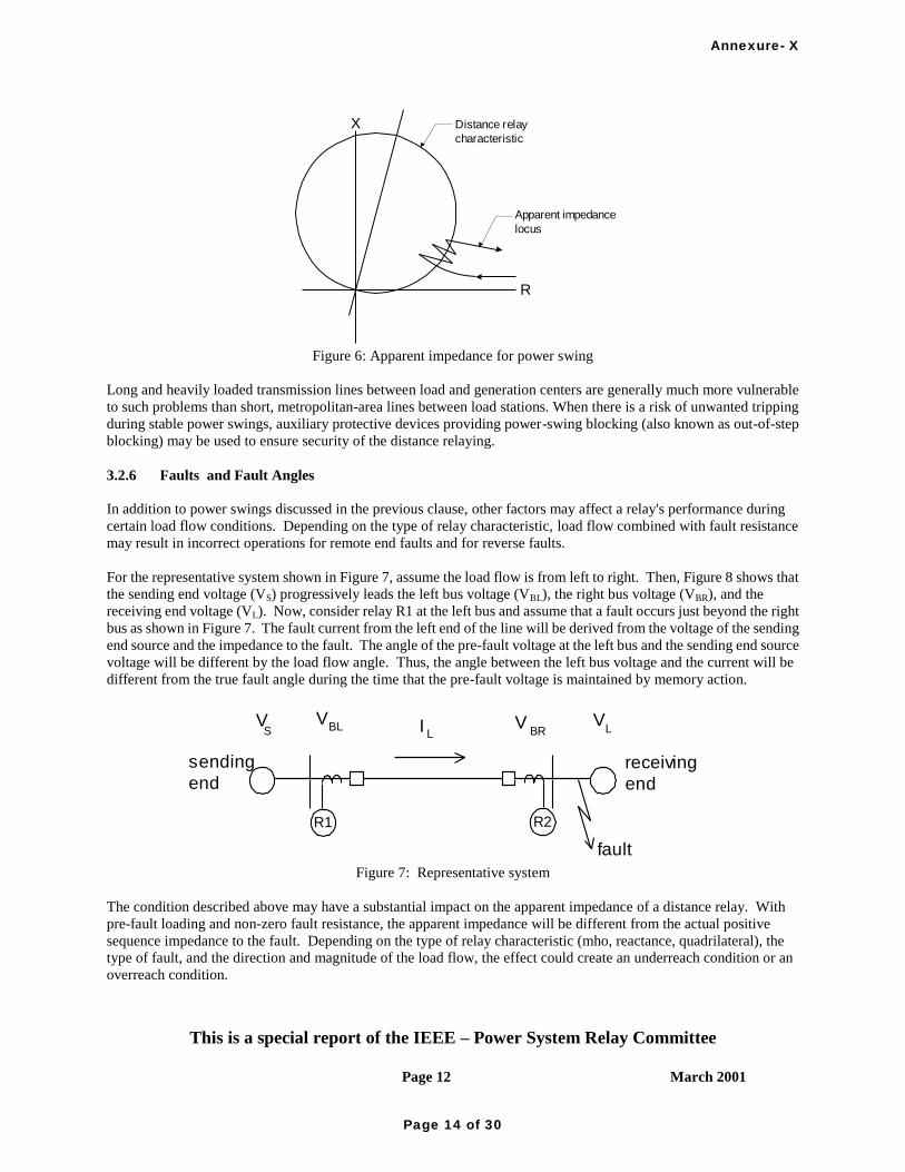
This is a special report of the IEEE – Power System Relay Committee
Page 12 March 2001
February 2001
Distance relay
characteristic
Apparent impedance
locus
X
R
Figure 6: Apparent impedance for power swing
Long and heavily loaded transmission lines between load and generation centers are generally much more vulnerable
to such problems than short, metropolitan-area lines between load stations. When there is a risk of unwanted tripping
during stable power swings, auxiliary protective devices providing power-swing blocking (also known as out-of-step
blocking) may be used to ensure security of the distance relaying.
3.2.6 Faults and Fault Angles
In addition to power swings discussed in the previous clause, other factors may affect a relay's performance during
certain load flow conditions. Depending on the type of relay characteristic, load flow combined with fault resistance
may result in incorrect operations for remote end faults and for reverse faults.
For the representative system shown in Figure 7, assume the load flow is from left to right. Then, Figure 8 shows that
the sending end voltage (VS) progressively leads the left bus voltage (VBL), the right bus voltage (VBR), and the
receiving end voltage (VL). Now, consider relay R1 at the left bus and assume that a fault occurs just beyond the right
bus as shown in Figure 7. The fault current from the left end of the line will be derived from the voltage of the sending
end source and the impedance to the fault. The angle of the pre-fault voltage at the left bus and the sending end source
voltage will be different by the load flow angle. Thus, the angle between the left bus voltage and the current will be
different from the true fault angle during the time that the pre-fault voltage is maintained by memory action.
sending
endreceiving
end
fault
R2R1
IL
VBR
VL
VBLV
S
Figure 7: Representative system
The condition described above may have a substantial impact on the apparent impedance of a distance relay. With
pre-fault loading and non-zero fault resistance, the apparent impedance will be different from the actual positive
sequence impedance to the fault. Depending on the type of relay characteristic (mho, reactance, quadrilateral), the
type of fault, and the direction and magnitude of the load flow, the effect could create an underreach condition or an
overreach condition.
Annexure- X
Page 14 of 30

This is a special report of the IEEE – Power System Relay Committee
Page 13 March 2001
February 2001
Another condition that could create an incorrect operation is a close-in reverse fault. Consider relay R2 at the right bus
and assume a single-line-to-ground fault with fault impedance at the right bus as shown in Figure 7. Figure 8 shows
the resulting pre-fault voltages with the assumed left to right load flow. In this case, the source voltage (VS) driving
the fault current will lead the initial polarizing voltage of the relay. Although the dynamic coincidence angle
calculated by the relay results in a non-trip condition, the steady-state angle between the relay operating voltage and
polarizing voltage will be less than 900. For some relay designs, this polarizing angle error can cause incorrect
operation on reverse faults.
VBL
VBR
VS
VL
Figure 8: Prefault voltages
In any case, the possibility of operating for an external fault during heavy load flow is extremely undesirable. This
operation could remove unfaulted equipment from service when the system is already stressed to its limit. Certain
relay designs have found ways to reduce the undesirable effects of load flow on relay performance. the protection
engineer should look for cautions in the relay manufacturer documentation related to load flow and settings. To
independently determine the amount and extent of the overreaching on particular relay designs, dynamic testing may
be necessary. This testing may be needed to determine if the steady-state margins generally applied to load
encroachment on protective relays are adequate for a particular zone of protection.
4. Solutions
4.1 Relay Settings
One significant solution to relay loadability issues is the selection of relay settings. The pickup of the relay as well as
the characteristic shape of the affected element can, in most cases, be varied by changing the settings of the relay. The
following is a discussion of how the relay settings can be varied to deal with loadability issues.
4.1.1 Line Coverage
Desired line coverage by distance elements is influenced by many factors including the protection scheme being used,
the measuring characteristics of the relay elements and system configuration. The chosen protection schemes using
distance elements can include non-pilot stepped zone schemes as well as any of several underreaching and
overreaching directional comparison pilot schemes. The characteristic of the distance elements in use can be one of
several different types including impedance, mho, offset mho, reactance, quadrilateral and lenticular. Due to the
varying shapes of these elements, a setting to obtain the desired reach at the line impedance angle can result in varying
sensitivities to load encroachment. System configuration has a large effect on the settings required in these schemes to
get effective coverage. Line length, number of line terminals, distribution transformer line taps and infeeds can all
Annexure- X
Page 15 of 30

This is a special report of the IEEE – Power System Relay Committee
Page 14 March 2001
February 2001
require overreaching elements to be set quite long. Obviously, the longer the required relay reach, the more likely a
loading problem can occur.
Using the equation:
Smax = V LL 2 / Z (where Z is the relay reach) (5)
gives a conservative estimate of whether the relay settings will pose a problem or not.
A typical transmission line may employ up to three or more zones of protection for multi-phase faults. These zones
may be employed in a high-speed pilot type protection scheme or in a stand-alone back-up scheme or in portions of
both schemes.
4.1.1.1 Forward Zones
Underreaching elements such as zone 1 rarely encounter a problem from load. If a loading problem were found to
exist for zone 1, the reach can usually be shortened to eliminate it. If zone 1 is used in an underreaching pilot scheme,
an overlap of the opposite zone 1 settings must be maintained. A zone 2 element is always required to reach the
remote bus with a least a 20-30% margin. Setting zone 2 at this minimum reach will not exceed the load limits in most
cases of two terminal lines. Other overreaching zones require much longer settings and are therefore susceptable to
loading problems. They generally exist to provide remote backup protection and tripping sensitivity. These zones
along with multiterminal zone 2 settings must accommodate infeed conditions which cause an increase in the required
reach. If loading is a problem for the overreaching zones they may be eliminated if their role of backup relaying is not
considered crucial. Otherwise, the loading problem must be handled using a selection of relay characteristic shapes,
blinders, load encroachment settings, or other solution.
4.1.1.2 Reverse Blocking Zones
In a directional comparison blocking scheme a reverse looking distance element is used to send block to the remote
terminal. It is set to reach behind its terminal and overreach the remote tripping relay by an adequate margin. Because
of the element‟s reach, it can be susceptible to load encroachment. If this element is only used to send a blocking
signal to the remote terminal it will not directly cause the line to trip due to load. The element could delay or prevent
tripping for internal line faults that would have other adverse consequences. In some schemes the reverse blocking
element also trips through a timer for backup protection. For these schemes, tripping would occur as a result of load
encroachment.
4.1.2 Backup Coverage
For lines with three terminals or lines with taps for distribution transformers, the effects of infeed and apparent
impedance cause overreaching Zone 2 and Zone 3 impedance settings to be increased. This also causes reverse
blocking impedance settings to be increased. As a result, these elements are the most susceptible to load
encroachment.
4.1.3 Breaker Failure
In order for the breaker failure overcurrent fault detection to be sensitive enough to cover at least the protected line, it
is often necessary to operate with the detector picked up constantly at times of heavy load. This is not usually a
problem as long as the breaker failure relay time delay is initiated by protective relay tripping and adequate time is
provided to allow overcurrent fault detector to reset after the breaker interrupts the fault. The specifications for the
Annexure- X
Page 16 of 30

This is a special report of the IEEE – Power System Relay Committee
Page 15 March 2001
February 2001
fault detector relay should be checked to make sure that the level of load current does not exceed the continuous rating
of the relay.
4.2 Dealing with Transients
By definition, transients are short time phenomena. If the transients result in measured parameters that enter the
operating characteristics of an instantaneous relay, it will trip. If the parameters enter the operating characteristic of a
time delayed relay it will trip only if no other protection or control action is taken to move the system conditions
outside the characteristic. The dual approach for line protection dealing with transients is to ensure that:
1. Measured parameters do not enter the operating characteristic of instantaneous protection
2. Time delayed protection is coordinated with other protection and control systems which are intended to
relieve the transient condition to an extent where the measured parameters do not enter the relay‟s operating
characteristics.
The following will consider the various measured parameters that may affect line protection systems.
4.2.1 Voltage
Transient voltage depressions usually have more significant effect on line protection systems than transient
overvoltages. Voltage depressions are often an indicator of a stressed or faulted system. If they are caused by a
faulted system, proper time coordination of the main and backup protection systems will ensure satisfactory operation.
However, if the voltage depression is caused by severe overloads, special protection systems, or operator action will
normally be required to deal with the problem. The line protection system will:
a.) either have to coordinate with special protection systems (if they exist),
b.) or be applied, and set, such that the maximum voltage depression during transient overload conditions will
not cause the measured parameters to enter the operating characteristics of the line protection system.
This second requirement means that protection systems should be applied and set such that the steady state operating
characteristic will not respond to voltage depressions during heavy overloads for which no automatic remedial action
is expected. It should be noted that low voltages on transmission systems are often accompanied by high reactive
power consumption that may cause the power factor of the load impedance to take on an unusually low value. Figure
9 from [6] shows the change in apparent impedance in two different types of load ((a) and (b)) as the voltage is varied
from 1.1 p.u. to 0.8 p.u..
Annexure- X
Page 17 of 30

This is a special report of the IEEE – Power System Relay Committee
Page 16 March 2001
February 2001
(a)
(b)
R
X
0.8
0.8
1.1 1.1
Figure 9 - Change in apparent impedances due to voltage changes.
It can be seen from Figure 9 that the change in apparent impedance is very dependent on the relationship of load
impedance to voltage. One phenomenon that can cause significant voltage depression is that of stalling motor loads.
Motors may stall due to slowly cleared faults [4] or slow voltage recovery following fault clearing. The increased
reactive power drawn by stalled motor loads can depress transmission voltages and cause load impedances to enter the
characteristics of long reaching distance relays.
The use of a lower than normal voltage (1.0 to 0.8 p.u.) to calculate the load limit of the distance relays; Smax =
VLL2/Z, clause 2.2.2; will compensate for the undervoltage condition that could occur with an overload condition.
4.2.2 Thermal Load
Thermal overload conditions may or may not result in voltage depressions, but are the result of unusually high
currents. Transmission lines are often able to withstand moderate overloads for several seconds, or even minutes.
Although short circuit protection is sometimes set to protect a line from overload, it is not the best way to provide such
protection. Short circuit protection (such as Zone 3 elements of distance relays) can never be expected to coordinate
with the thermal overload capability of transmission lines. If lines are expected to be able to sustain temporary
overloads, either adequate operator control should be ensured, or specifically designed thermal overload protection
should be applied (see clause 3.1.1.5). The thermal overload protection should be able to coordinate as much as
possible with the temporary overload capability of the protected line.
4.2.3 Load Angle
Very heavy loads resulting in high load angle across a transmission line may cause certain types of distance relays to
become blind to remote phase to phase short circuits[3]. In this situation, the security of the line protection is not
threatened as much as the dependability to sense all faults in the protected zone. For this reason, transient conditions
that result in a high load angle, without associated voltage depression or thermal overload can usually be tolerated until
operator action can reduce the load angle.
Annexure- X
Page 18 of 30

This is a special report of the IEEE – Power System Relay Committee
Page 17 March 2001
February 2001
4.2.4 Outages – Three Phase and Single Phase
Transmission line outages due to temporary faults are usually restored to normal by automatic reclosing. Tripping
may be single phase or three phase.
In the case of three phase tripping, parallel circuits may be temporarily overloaded, or may be subjected to reduced
voltages or high load angles or swings. In such cases, the comments noted above regarding those transient conditions
become applicable.
In the case of single phase tripping, the faulted line is still able to carry a portion of load, and possibility of problems
due to high (balanced) load in parallel circuits is reduced. However, while the single phase is open, the surrounding
power system is subject to a certain amount of unbalance, and line protection in adjacent or parallel circuits (such as
negative or zero sequence overcurrent protection) may misoperate due to the unbalance resulting from load flow
through the faulted line [5].
In such cases, the sensitive unbalance protection must be time delayed to coordinate with the reclosing and maximum
expected pole discordance time of the line with single phase tripping.
4.3 Protective Equipment
There are several features and options that may be available in protective equipment which can allow a protective
device to be less sensitive to load current while still providing the desired fault protection settings.
4.3.1 Distance Relay Characteristic Shape
A lenticular, rectangular, or even more sophisticated characteristic enables a relay to protect the line, provide
maximum resistive fault coverage, and still avoid overlapping with the load regions on the impedance plane. This
applies to underreaching zone 1, as well as to overreaching zones 2 and 3, and the reverse zone used by distance
blocking pilot schemes and for remote breaker failure. Appendix B discusses the different characteristic shapes in
more detail.
4.3.2 Use of blinders
A blinder is an element of a distance relay that can be used to restrict the operating characteristic of the relay. One
common blinder is a straight line characteristic on the R-X diagram and generally at an angle from 60 to 90 degrees
positive from the R axis. The straight line is positioned to limit the resistive reach of the distance relay. Another type
of blinder has a more complex characteristic that restricts the operation of the distance relay in an area near the R axis.
Both types of blinders are typically used in combination with a mho characteristic. The combination of the mho
characteristic and a blinder is set to protect the line and limit the area of tripping for steady state conditions in the
region of load and therefore reducing the limitation the distance relay would have on line loading. Figure 10 shows
both types of blinders applied with a mho relay. Typically only one type of blinder would be used in a given
application.
Annexure- X
Page 19 of 30

This is a special report of the IEEE – Power System Relay Committee
Page 18 March 2001
February 2001
R
X
Blinder No. 1
Blinder No. 2
Figure 10: Blinder characteristics
If the mho and the blinder characteristics are produced by two different relay functions the combination may have
different reaction times to changing fault and load conditions. The transient reaction of the combination may lead to
greater difficulties with transient overreach for a fault just beyond the length of the line with previous heavy load flow.
Care must also be taken that a stable fault swing after heavy load flow does not activate a mho relay implementing
blinder characteristic. Creating both the mho and blinder characteristics with algorithms in a single microprocessor
relay removes this concern.
4.3.3 Power Swing Blocking
Transmission line distance relays are susceptible to tripping on stable and unstable swings where the apparent
impedance presented to the relay enters the operating characteristic. Where operation of the line protection due to
swings could cause undesirable consequences, the protection may be supplemented by additional protection
(out-of-step protection) to detect the swing condition. The out-of-step protection is usually set to detect the swing
before the short circuit protection would operate. The out-of-step protection may be used to block the distance
protection and/or to trip the line at an optimum line angle. When out-of-step protection blocks a line trip, it should be
ensured that the out-of-step condition will be eliminated by some other means of separating the two asynchronous
sources. Thus out-of-step blocking is often only applied in association with out-of-step tripping at some other
preferable separation point. (see clause 3.2.5)
Transmission line protection systems that depend on a phase comparison or differential protection technique will not
sense swings that are centered in the protected line. Out-of-step tripping protection may be used to supplement
differential or phase comparison protection where line opening on an out-of-step condition is required.
A typical out-of-step blocking scheme uses two separate regions on the impedance plane and monitors the timing of
the apparent impedance entering the two regions (outer and inner). Fast movements indicate a fault, slow transitions
indicate a power swing. The problem is that the two zones must have finite size difference. The outer region may
overlap with the region of increased load. A distance relay with out-of-step blocking will require more room to keep its
out-of-step outer zone between the regions of increased load and inner line impedance.
Annexure- X
Page 20 of 30

This is a special report of the IEEE – Power System Relay Committee
Page 19 March 2001
February 2001
4.3.4 Adaptive techniques
In many microprocessor-based relays, settings can be changed using setting groups to accommodate system
conditions (e.g. load level, generators or lines in/out of service). At the present time, adaptive techniques that
automatically modify settings according to measured system conditions have not been widely used.
4.4 Systems
Loadability must be considered when designing an overall system. All aspects of the design, the operations, the
automatic systems, and the protection system must coexist and work together to fulfill the overall design criteria. The
intent of the transmission planners, the purpose of the operating constraints, and the protection system limits all have
to be considered when trying to satisfy a loadability limit.
4.4.1 Planning
With respect to transmission line loadability, it is prudent for the design of a protection system to be closely
coordinated with the planning of transmission facilities. If additional terminals to the surrounding transmission
network were proposed to be added to a transmission line, the proposed terminals will introduce short circuit current
infeeds to the line. If a transmission line is protected by a directional comparison pilot protection system supervised
by impedance elements, the new terminals will necessitate an extension of the reaches of these impedance elements. If
this extension of impedance relay reach results in an undesirable decrease in line loadability, then another type of
protection system (i.e. phase comparison instead of directional comparison) must be considered.
4.4.2 Controlled Flows on Lines
Reconfiguring the power system can often control load flows to reduce an overload condition on a transmission line.
Phase shifting transformers or other modern flexible ac transmission technology techniques may also be used to
control the load flows on transmission lines.
4.4.3 Load Shedding
When transmission lines become severely overloaded, it may be necessary to shed load in order to maintain integrity
of the power grid. Load shedding can be accomplished by manual load shedding, automatic load shedding (e.g.
undervoltage load shedding), or via SCADA.
4.4.4 Series-Compensated Lines
Series Capacitors (SCs) have become an important element in economical long distance power transmission. The main
purpose for using SCs is to decrease the effective inductive reactance of a power line. The following benefits can be
achieved:
increased power transfer capability (Figure 11).
improved power system stability,
reduced system losses,
improved voltage control,
better power regulation.
Annexure- X
Page 21 of 30

This is a special report of the IEEE – Power System Relay Committee
Page 20 March 2001
February 2001
series compensated line
00 22.50 450 900 112.5 0 1350 1800
POWER ANGLE
P1
XL - line reactance
67.50 157.5 0
PO
WE
R
P2
plain line
XC - capacitor reactance
- power angle
LX
sVrVP max
CXLX
sVrVP
max
Figure 11: Comparison of the loadability of uncompensated and series compensated lines
The cost of increasing line loadability by installing SCs, compared to constructing a new equivalent line, is usually in
the order of 15-30%. The amount of series compensation is typically limited to 60-70% of the line reactance in order to
avoid undesirable subsynchronous oscillations. The series capacitance can be installed entirely in one location, either
in the substation or someplace along the line (typically mid-line). Otherwise, the series capacitance is split between
several (typically two) banks of capacitors installed at both ends of the line.
Series capacitors are normally equipped with both automatic and manually operated bypass facilities to protect the
capacitors from overvoltage during faults and to enable operation of the line while the capacitors are out of service.
Protective relaying for series compensated lines must be capable of accommodating the maximum power transfer with
the capacitors in service, yet also be able to detect faults at the remote end of the line with the capacitors bypassed.
Since series compensated lines are usually long lines, special attention is needed to be sure that the selected line
protection will not limit the load transfer capability of the line.
Annexure- X
Page 22 of 30

This is a special report of the IEEE – Power System Relay Committee
Page 21 March 2001
February 2001
5. Summary
The essential goal of relay system design with respect to loading is to ensure that no unintended relay operations occur
during conditions created by system load. The fundamental definitions of relay load limits are discussed. Calculations
of limits are covered for the most common relay types. Examples of calculations for overcurrent and mho impedance
type relays are provided in Appendix A. These calculations are made to assure that the relays will not trip under
maximum load conditions.
Beyond the fundamental issues, many factors that have the potential to limit loading need to be considered. Some of
these factors are directly related to the relays. These include not only the settings, but also the choices of relays and
relay schemes. Many system factors will also affect the application and performance of relaying systems. Included are
line ratings, loading, power factors, load balance, and multiterminal connections. The effects of swings and faults are
also included.
Once the problems related to loading are outlined and discussed, the next step is to begin to address them. The
solutions discussed are accomplished through relay settings, selection of equipment, and design of schemes applied to
prevent load problems on relaying systems. Many times, careful planning and control of the system operating issues
can help prevent load problems from occurring.
Annexure- X
Page 23 of 30
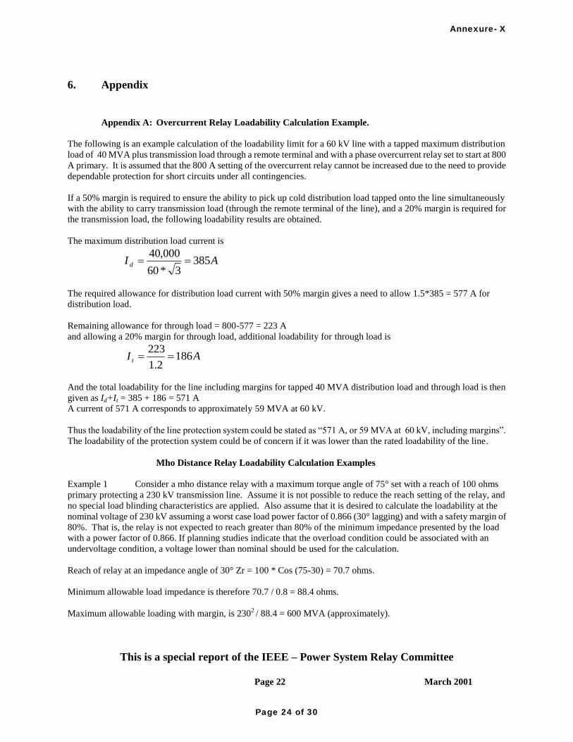
This is a special report of the IEEE – Power System Relay Committee
Page 22 March 2001
February 2001
6. Appendix
Appendix A: Overcurrent Relay Loadability Calculation Example.
The following is an example calculation of the loadability limit for a 60 kV line with a tapped maximum distribution
load of 40 MVA plus transmission load through a remote terminal and with a phase overcurrent relay set to start at 800
A primary. It is assumed that the 800 A setting of the overcurrent relay cannot be increased due to the need to provide
dependable protection for short circuits under all contingencies.
If a 50% margin is required to ensure the ability to pick up cold distribution load tapped onto the line simultaneously
with the ability to carry transmission load (through the remote terminal of the line), and a 20% margin is required for
the transmission load, the following loadability results are obtained.
The maximum distribution load current is
AI d 3853*60
000,40
The required allowance for distribution load current with 50% margin gives a need to allow 1.5*385 = 577 A for
distribution load.
Remaining allowance for through load = 800-577 = 223 A
and allowing a 20% margin for through load, additional loadability for through load is
AI t 1862.1
223
And the total loadability for the line including margins for tapped 40 MVA distribution load and through load is then
given as Id+It = 385 + 186 = 571 A
A current of 571 A corresponds to approximately 59 MVA at 60 kV.
Thus the loadability of the line protection system could be stated as “571 A, or 59 MVA at 60 kV, including margins”.
The loadability of the protection system could be of concern if it was lower than the rated loadability of the line.
Mho Distance Relay Loadability Calculation Examples
Example 1 Consider a mho distance relay with a maximum torque angle of 75° set with a reach of 100 ohms
primary protecting a 230 kV transmission line. Assume it is not possible to reduce the reach setting of the relay, and
no special load blinding characteristics are applied. Also assume that it is desired to calculate the loadability at the
nominal voltage of 230 kV assuming a worst case load power factor of 0.866 (30° lagging) and with a safety margin of
80%. That is, the relay is not expected to reach greater than 80% of the minimum impedance presented by the load
with a power factor of 0.866. If planning studies indicate that the overload condition could be associated with an
undervoltage condition, a voltage lower than nominal should be used for the calculation.
Reach of relay at an impedance angle of 30° Zr = 100 * Cos (75-30) = 70.7 ohms.
Minimum allowable load impedance is therefore 70.7 / 0.8 = 88.4 ohms.
Maximum allowable loading with margin, is 2302 / 88.4 = 600 MVA (approximately).
Annexure- X
Page 24 of 30

This is a special report of the IEEE – Power System Relay Committee
Page 23 March 2001
February 2001
Example 2 A certain 138 kV line has recently been rated for 346 MVA under emergency or peak conditions.
The company requires a 5% margin for relay pickup at 30 degree power factor. One end of the line has a relay with a
forward looking mho setting of 90 ohms at 82 degrees. The setting is checked as follows:
Zr = 90 * COS (82-30) = 55.4 ohms
1382 / 55.4 = 344 MVA (approximately)
This value is below the desired rating of 346 MVA. Working backward using the 5% margin:
346 * 1.05 = 363 MVA
1382 / 363 = 52.46 ohms
Zr = 52.46 * COS(82-30) = 85 ohms
The setting is being used as remote back up. A reduction in the pickup from 90 to 85 ohms can be accommodated
without any serious problems.
Appendix B: Fundamentals of Distance Relays
Distance relays are a family of relays that determine whether or not the impedance from a relay location to a fault is
within the operating characteristic of the relay. The relays accomplish this by using the magnitude of voltage and
current, and the phase angle between the two. The characteristic of this relay type can be described using a
resistance-reactance (R-X) diagram. Some of the distance relays are better at handling heavy line loads than others.
Since the first type of distance relays used were impedance relays, the terms distance relay and impedance relay are
sometimes incorrectly used interchangeably. The basic impedance relay‟s characteristic when plotted on an R-X
diagram is a circle around the origin. The relay is non-directional, so it was most often used with a directional unit.
The combination of the impedance unit and the directional unit produces a tripping area inside the circle of the
impedance unit that occupies all angles within the first quadrant and parts of those within the second and fourth
quadrants. (Figure 12) This type of distance relay is more sensitive to heavy loads than other distance relays. The
relay‟s sensitivity to faults on the protected line and its sensitivity to load in the forward direction are equal. (Note
that the forward direction is here defined by current flowing from the substation where the relay is located.)
Annexure- X
Page 25 of 30
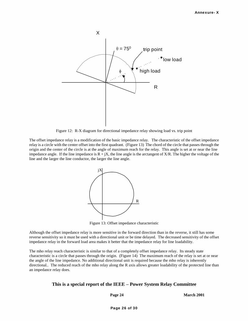
This is a special report of the IEEE – Power System Relay Committee
Page 24 March 2001
February 2001
X
R
low load
high load
trip pointq = 750
f
Figure 12: R-X diagram for directional impedance relay showing load vs. trip point
The offset impedance relay is a modification of the basic impedance relay. The characteristic of the offset impedance
relay is a circle with the center offset into the first quadrant. (Figure 13) The chord of the circle that passes through the
origin and the center of the circle is at the angle of maximum reach for the relay. This angle is set at or near the line
impedance angle. If the line impedance is R + jX, the line angle is the arctangent of X/R. The higher the voltage of the
line and the larger the line conductor, the larger the line angle.
jX
R
Figure 13: Offset impedance characteristic
Although the offset impedance relay is more sensitive in the forward direction than in the reverse, it still has some
reverse sensitivity so it must be used with a directional unit or be time delayed. The decreased sensitivity of the offset
impedance relay in the forward load area makes it better that the impedance relay for line loadability.
The mho relay reach characteristic is similar to that of a completely offset impedance relay. Its steady state
characteristic is a circle that passes through the origin. (Figure 14) The maximum reach of the relay is set at or near
the angle of the line impedance. No additional directional unit is required because the mho relay is inherently
directional.. The reduced reach of the mho relay along the R axis allows greater loadability of the protected line than
an impedance relay does.
Annexure- X
Page 26 of 30

This is a special report of the IEEE – Power System Relay Committee
Page 25 March 2001
February 2001
jX
R
Figure 14: Mho characteristic
A reverse offset mho relay is a mho relay with the center of the circle offset in the direction of the origin. The offset
mho relay, like the offset impedance relay, has a zone of sensitivity to faults in the reverse direction. The offset mho
relay is applied in cases where it is important to include the origin in the trip zone and the unit is time delayed.
A forward offset mho relay is a mho relay with the center of the circle offset away from the origin. A forward offset
mho characteristic can provide good backup protection for remote forward resistive faults, without the load
encroachment problems of a mho element with no forward offset. Figure 15 shows a forward offset mho relay used in
conjunction with a mho element.
R
X
Forward
Offset Mho
Mho
Figure 15: Mho and forward offset mho characteristics
For shorter lines the impedance and the offset impedance relays provide limited fault resistance coverage. For short
line applications the type of distance relay called a reactance relay is used. The characteristic on a R-X diagram is a
line drawn parallel to the R axis in the first and second quadrant. The distance the line is away from the R axis is
determined by the setting reach of the relay. The reactance relay is directional but its reach in the resistive direction is
Annexure- X
Page 27 of 30

This is a special report of the IEEE – Power System Relay Committee
Page 26 March 2001
February 2001
only limited by the energy requirements of the unit. This makes the reactance relay very sensitive to load. To correct
for this limitation, the relay is used in conjunction with a mho or an offset impedance relay to limit the resistive reach.
(Figure 16)
jX
R
ZONE 3
ZONE 2
ZONE 1
Figure 16: Self-polarized Mho and reactance characteristic
A variation to the reactance relay is a quadrilateral relay. With the quadrilateral relay the limit of its reach in the
resistive directions are straight lines on a R-X diagram instead of using a mho element. (Figure 17) The reach in the
area of forward load flow is limited by a discrete setting on the relay.
jX
R
ZONE 1
ZONE 3
ZONE 2
Figure 17: Quadrilateral characteristic
The mho relay characteristic can be described by measuring the angle between the operating phasor of (IZ - V) and the
phasor (Vpol). Where I is the line current, Z is the reach of the relay at the maximum reach angle, V is the voltage at the
relay location, and Vpol is the polarizing voltage. When the characteristic is defined by the angle being 90 degrees,
then the characteristic is a circle. If the characteristic is defined by an angle between the phasors being greater than 90
degrees, the characteristic has a lenticular (lens) shape. (Figure 18) The lenticular characteristic allows increased
loading on the line compared to the true mho relay but also has less sensitivity to faults with fault resistance.
R
jX
Figure 18: Lenticular characteristic
Annexure- X
Page 28 of 30

This is a special report of the IEEE – Power System Relay Committee
Page 27 March 2001
February 2001
7. References
[1] IEEE C37.90-1989 (R1994) IEEE Standard for Relays and Relay Systems Associated with Electric Power
Apparatus
[2] IEEE C57.13-1993 IEEE Standard Requirements for Instrument Transformers
[3] R.J. Marttila, “Effect of Transmission Line Loading on the Performance Characteristics of Polyphase Distance
Relay Elements”, IEEE Trans. on Power Delivery, Vol. 3, No. 4, Oct. 1988, p 1466-74.
[4] B.R. Williams, W.R. Schmus, D.C. Dawson, “Transmission Voltage Recovery Delayed by Stalled Air Conditioner
Compressors,” IEEE Trans. On Power Systems, Vol.7, No.3, Aug. 1992, pp. 1173-78.
[5] Estergalyos, J. –chairman, “Single Phase Tripping and Auto Reclosing of Transmission Lines-- IEEE Committee
Report”, IEEE Trans. on Power Delivery, Vol. 7, No. 1, Jan. 1992 p 182-192.
[6] IEEE Power System Relaying Committee Working Group, "Summary of System Protection and Voltage
Stability," IEEE Transactions on PowerDelivery, Vol 10, No 2, April 1995, p 631-638.
8. Bibliography
M. Mir, “Adaptive vs. Conventional Reach Setting of Digital Distance Relays,” Electric Power Systems Research,
Vol. 43, 1997, p 105-11.
S. Pickering, “Application Benefits of Numerical Distance Protection,” 49th Annual Texas A&M Protective Relay
Conference Apr 15-17, 1996.
J. Roberts, E.O. Schweitzer, R. Arora, E. Poggi, “Limits to the Sensitivity of Ground Directional and Distance
Protection,” 49th Annual Texas A&M Protective Relay Conference Apr 15-17, 1996.
T. Yanagihashi, S. Kumano, T. Nomura, T. Kubo, M. Hatata, E. Ibaragi, I. Mitani, “Improved Protection Relays to
Cope With Changes in Power Transmission Networks and Their Operating Conditions,” CIGRE, Paris, Aug 28-Sep 3,
1994, Paper No. 34-201.
G. Sweezy, G. Swift, R. Coish, “A Delta-Current Admittance Relay For Line Loadability Enhancement,” 21st Annual
Western Protective Relay Conference, Oct 18 - 20, 1994.
G.E. Alexander, J.G. Andrichak, W.Z. Tyska, “Relaying Short Lines,” Texas A&M Protective Relaying Conference,
Apr. 15-17, 1991.
A.T. Giuliante, J. Gosalia, G.K. Clough, “A Multi-Processor Approach to Distance Protection,” Western Protective
Relay Conference, Spokane, WA, Oct. 22-5, 1990.
J. Crockett , W.A. Elmore, “Performance of Phase-to-Phase Distance Units,” Texas A&M Relay Conference, Apr.
1987.
A. T Johns, A. A. El-Alaily, “New Distance Protective Relay With Improved Coverage for High-Resistance Earth
Faults,” Proceedings of the Institution of Electrical Engineers. (Great Britain), Vol. 124, No. 4, April 1977, p 349-55
Annexure- X
Page 29 of 30

This is a special report of the IEEE – Power System Relay Committee
Page 28 March 2001
February 2001
W. D. Humpage, J. Rushton, “Power-System Studies for the Determination of Distance-Protection Performance,”
Proceedings of the Institution of Electrical Engineers (Great Britain), June 1972, Vol. 119, No. 6, pp. 677-688
G.E. Alexander, J.G. Andrichak, W.Z. Tyska, S.B. Wilkinson, “Effects of Load Flow on Relay Performance,” Texas
A&M Relay Conference, April 1986.
Gary C. Bullock, “Cascading Voltage Collapse in West Tennessee – August 22, 1987”, 17th
Annual Western
Protective Relay Conference October 25, 1990
Annexure- X
Page 30 of 30

S.
No
Name of
Substation Details of work Status of Implementation of Protection Audit Recommendations Remarks
S.
N
Name of
Substation Details of work Status of Implementation of Protection Audit Recommendations Remarks
PLCC protection panels for Srisailam and Chalakurthy are not
available. Provision for the same to be done
Shall be provided.
Latest Update vide mail on 01-02-2016:
PLCC Protection panels Erection is under the Scope of TSTRANSCO.
The issue was discussed in PCSC-51 held on 25-02-2016 and it was made clear that the responsibility of complying
with this recommendations lies with TSGENCO.
Pending
PLCC panel is erected but not commissioned
It will be reviewed.
Latest Update vide mail on 01-02-2016:
Procurement is in advance stage (Order is going to be placed by TSTRANSCO)
The issue was discussed in PCSC-51 held on 25-02-2016 and it was made clear that the responsibility of complying
with this recommendations lies with TSGENCO.
Pending
S.
N
Name of
SubstationDetails of work Status of Implementation of Protection Audit Recommendations Remarks
S.
N
Name of
SubstationDetails of work Status of Implementation of Protection Audit Recommendations Remarks
Phase-II
1 220 KV
Srisailam
Project SS
Review of certain Protection Audit Recommendations of SR-Constituents
APGENCO (HYDEL)
PLCC: No carrier protection coupler is available in 220 kV
station feeders
Provided for Tallapally-1&2 feeders and will be procured and commissioned for remaining feeders by 31-08-2015.
APGENCO Mail received on 09-02-2016:
Provided for Tallapally-1&2 feeders and will be procured and commissioned for remaining feeders (under
APTRANSCO scope).
The issue was discussed in PCSC-51 held on 25-02-2016 and it was made clear that the responsibility of complying
with this recommendations lies with APGENCO.
Pending
5 220 kV Jurala
Generating
Station
3 220 kV N'Sagar
TSGENCO
Phase I
Phase I
Phase I & Phase-II
1 400 kV
Srisailam LB
S/S (Gen)
TSTRANSCO
PlCC 48 V DC single battery set is available. No redundant
battery set with charger. Failure may affect carrier protection
and real time data loss to the system operator due to
communication Equipment power loss
Latest Update vide mail on 01-02-2016:
Will be reviewed at site and procurement action will be initiated accordingly.
The issue was discussed in PCSC-51 held on 25-02-2016 and it was made clear that the responsibility of complying
with this recommendations lies with TSGENCO.
Pending
Annexure- XI
Page 1 of 3

10 400kV side of
400/ 220 kV
Gajwel
SubstationReplacement of PLCC panels of 400 kV Ramagundam line to be
done
Latest Update vide mail on 25-01-2016:
Under PGCIL Scope. PGCIL authories have informed that the panels will be replaced soon as their indent for
material is under process.
The issue was discussed in PCSC-51 held on 25-02-2016 and it was made clear that the responsibility of complying
with this recommendations lies with TSTRANSCO.
Pending
S.
No
Name of
Substation Details of work Status of Implementation of Protection Audit Recommendations Remarks
2 400 kV
Palakkad SS
[PGCIL (SR-
II)]
Outsource supply supplied from 11 kV Para feeder is having
low reliability and hence alternate arrangements to be made for
reliable supply.
Latest Update as on 24-08-2015:
The tertiary supply from ICT#2 erection completed. Request for availing aux supply is being processed by KSEB.
The issue was discussed in PCSC-51 held on 25-02-2016 when PGCIL (SR-II) informed that they had started
availing supply from the tertiary of ICT # 2 from 3rd week of Jan, 2016.
Complied
S.
No
Name of
SubstationDetails of work Status of Implementation of Protection Audit Recommendations Remarks
1 400 kV NTPC
Ramagundam
S/S (Gen)
Distrubance Recorders (ABB, INDACTIC) not having GPS
time synchronisation (for 400 kV Warangal Line, 400 kV
Gajwel Line, 400 kV Malkaram Line, 400 kV Hyderabad Line #
3, 400 kV Hyderabad Line # 4), 400 kV Dichipalli Numerical
relay (DR) not having GPS time synchronisatiion.
a) These disturbance recorders are connected to a PC. The PC has now been time synchronized through GPS. The PC
synchronizes the DRs with the batch process (WINCOM) on regular basis. - Complied
b) 400 kV Dichipalli Numerical relay (DR): Time synch problem has been taken up with APTRANSCO, the owner
of the equipment. - Taken up with APTRANSCO : Dec-15
The issue with regard to time synchronisation of Dichipally feeders numerical relay was discussed in PCSC-51 held
on 25-02-2016 and it was made clear that the responsibility of complying with this recommendations lies with
TSTRANSCO. It was also agreed to drop this remark from the scope of NTPC-Ramagundam and include it under
TSTRANSCO scope.
NTPC - Complied;
TSTRANSCO - Pending
S.
No
Name of
SubstationDetails of work Status of Implementation of Protection Audit Recommendations Remarks
The Line CVT in the Y phase of the feeder was not available in
all the feeders except SP koil 2 : To be reviewed
Communicated to TANTRANSCO.
The issue was discussed in PCSC-51 held on 25-02-2016, and it was made clear that the responsibility of complying
with this recommendations lies with MAPS (NPCIL).
Pending
S.
No
Name of
Substation Details of work Status of Implementation of Protection Audit Recommendations Remarks
Phase-II
NTPC
PGCIL
(Phase I & II)
2 230KV MAPS
Kalapakkam
S/S (Gen)
(Phase I & II)
NPCIL
(Phase I & II)
OTHERS
Annexure- XI
Page 2 of 3

a) Distance protection, Zone- 4 timing adopted was: 1.2 sec;
Recommended 0.9 sec
GMR mail received on 09-09-2015:
As per telephonic advice by DE power system the settings retained as same because this was envisage and corrected
during commissioning by AP Transco Officials with concern of DE power System.
GMR mail received on 28-01-2015:
GMR have submitted a letter to APTRANSCO seeking the permission to issue an Approval for setiings
recommended by the protection audit team.
GMR mail received on 08-02-2016:
Settings as per CE-IPC & Power System.
The issue was discussed in PCSC-51 held on 25-02-2016 and the forum had agreed to the settings adopted by GMR
as suggested to them by APTRANSCO. And the item was dropped.
Dropped
f) Synchro check (29) Adopted: ON; Recommended: OFF
GMR mail received on 09-09-2015:
As per telephonic advice by DE power system the settings retained as same because this was envisage and corrected
during commissioning by AP Transco Officials with concern of DE power System.
GMR mail received on 28-01-2015:
GMR have submitted a letter to APTRANSCO seeking the permission to issue an Approval for setiings
recommended by the protection audit team.
GMR mail received on 08-02-2016:
GMR informed that they would adopt the recommedned setting in presence of APTRANSCO officials.
Pending
For 220kV Line #2 Distance protection, Zone-4 timing adopted
was: 1.2 sec; Recommended : 0.9 sec
GMR mail received on 09-09-2015:
As per telephonic advice by DE power system the settings retained as same because this was envisage and corrected
during commissioning by AP Transco Officials with concern of DE power System.
GMR mail received on 28-01-2015:
GMR have submitted a letter to APTRANSCO seeking the permission to issue an Approval for setiings
recommended by the protection audit team.
GMR mail received on 08-02-2016:
Settings as per CE-IPC & Power System.
The issue was discussed in PCSC-51 held on 25-02-2016 and the forum had agreed to the settings adopted by GMR
as suggested to them by APTRANSCO. And the item was dropped.
Dropped
5 220 kV GMR
Barge,
Kakinada S/S
(Gen)
In 220 kV line # 1, main # 1 & 2 protection relay following deviations observed:Annexure- XI
Page 3 of 3

Annexure-XII
Page 1 of 96

S. No Name of
Substation Details of work Status of Implementation of Protection Audit Recommendations Remarks
Distance protection relay settings, power swing
block settings to be reviewed for 220 kV linesImplemented. Complied
Disturbance recorder, Station Event logger and
GPS to be made available
Procurement action is initiated and will be procured by 31-03-2015. Commissioning will be completed by 31-05-
2015.
APGENCO Mail received on 09-02-2016:
Tender Process completed and Placing of Purchase Order was kept on hold for want of clearance from NLDC
regarding grant of funds.
APGENCO mail received on 29-02-2016:
Tender Process completed and Placing of Purchase Order was kept on hold for want of clearance from NLDC
regarding grant of funds. Procurement will be completed by 6 months, and Work will be completed within 6 months
thereafter. Hence total time extension required is upto Dec-2017. (Estimated that funding process will be completed
within one year.
Pending
In Tallapalli feeder-1 (P442) relay configuration
of voltage protection, CB failure are disabled. It
is also noticed that KZ RES component and
angle different from approved settings. Same to
be reviewed
Complied
In N.Sagar line (P442) relay configuration of
voltage protecgtion, CB failure and interval auto
reclose configuration disabled instead of enable
mode. KZ RES component and angle different
from approved setting. Same to be reviewed
Complied
All static relays like distance relay, differential
relay and Bus-Bar relays to be replaced with
latest version numerical relays having inbuilt
D.R
Procurement action is initiated and will be completed by 31-03-2015.Commissioning of the same will be completed
by 31-08-2015 subjected to availability of Line Clear.
APGENCO Mail received on 09-02-2016:
Tender Process completed and Placing of Purchase Order was kept on hold for want of clearance from NLDC
regarding grant of funds.
APGENCO mail received on 29-02-2016:
Tender Process completed and Placing of Purchase Order was kept on hold for want of clearance from NLDC
regarding grant of funds. Procurement will be completed by 6 months, and Work will be completed within 6 months
thereafter. Hence total time extension required is upto Dec-2017.
Pending
STATUS OF IMPLEMENTATION OF PROTECTION AUDIT RECOMMENDATIONS
APGENCO (HYDEL)
Phase-I
1 220 kV Srisailam
Separate LBB is available and hence Breaker failure is not enabled. Over voltage protection is not required as per
APTRANSCO and hence not implemented. KZ resistive component settings are verfied with APRTANSCO and
found correct.
Annexure-XII
Page 2 of 96

Earth resistance measuring instrument to be
procured.Procured. Complied
The Generator differential protection, GT O/C+
E/F protection , GT REF Protection, Overflux
protection , UAT O/C + E/F protection settings
to be duplicated and provided in Main-2 relay
for increasing the reliability.
Procurement action is initiated and will be completed by 31-03-2015.Commissioning of the same will be completed
by 31-08-2015 subjected to availability of Line Clear.
APGENCO Mail received on 09-02-2016:
Tender Process completed and Placing of Purchase Order was kept on hold for want of clearance from NLDC
regarding grant of funds.
APGENCO mail received on 29-02-2016:
Tender Process completed and Placing of Purchase Order was kept on hold for want of clearance from NLDC
regarding grant of funds. Procurement will be completed by 6 months, and Work will be completed within 6 months
thereafter. Hence total time extension required is upto Dec-2017.
Pending
Older version of unit 4 Main-I & II relay (REG
316*4) relay to be replaced with REG 670 or
other similar relay as provided for other units
Already replaced with new ABB make REG-670 type protection relay panel for both Main-I and Main-II in February-
2014 and is in service.Complied
GPS to be provided for time synchronization of
protection system
GPS already procured along with SCADA and will be commissioned with switchyard SCADA latest by 31-03-2015.
APGENCO Mail received on 09-02-2016:
Tender Process completed and Placing of Purchase Order was kept on hold for want of clearance from NLDC
regarding grant of funds.
APGENCO mail received on 29-02-2016:
Tender Process completed and Placing of Purchase Order was kept on hold for want of clearance from NLDC
regarding grant of funds. Procurement will be completed by 6 months, and Work will be completed within 6 months
thereafter. Hence total time extension required is upto Dec-2017.
Pending
1 220 kV Srisailam
2 220 kV Srisailam
power station
(right bank)
Annexure-XII
Page 3 of 96

S. No Name of
SubstationDetails of work Status of Implementation of Protection Audit Recommendations Remarks
Station Battery is recently commissioned. It is a
single source mDCV & charger. No stand by is
available.
Back up supply is arranged from power house by laying a cable.
APGENCO Mail received on 09-02-2016:
Backup supply is arranged from power house battery system by laying a separate cable as a temporary
measure.However proposal is also made for procurement of new battery set with Battery charger in PSDF-DPR and
will be procured and commissioned within 12 months, after getting grants from PSDF.
APGENCO mail received on 29-02-2016:
Backup supply is arranged from power house battery system by laying a separate cable as a temporary measure.
However proposal is also made for procurement of new battery set with Battery charger in PSDF-DPR and the
Procurement will be completed by 6 months, and Work will be completed within 6 months thereafter. Hence total
time extension required is upto Dec-2017.
Pending
Phase-II
1 220 KV Srisailam
Project SS
Pending
All 220 KV CTs were replaced with 0.2 class CTs except for 2 two feeders. For these two feeders CTs replacement
will be taken up shortly.
APGENCO Mail received on 09-02-2016:
1. A total of 10Nos. CBs were replaced with new ones and 4 Nos. were proposed for PSDF funding.
2. A total of 33Nos. CTs were replaced with new ones and 24 Nos. were proposed for PSDF funding.
Balance items will be completed within 12 months from obtaining clearance of grants from PSDF.
APGENCO mail received on 29-02-2016:
1. A total of 10Nos. CBs were replaced with new ones and 4 Nos. were proposed for PSDF funding.
2. A total of 33Nos. CTs were replaced with new ones and 24 Nos. were proposed for PSDF funding.
Procurement of balance items will be completed by 6 months, and Work will be completed within 6 monhts
thereafter. Hence total time extension required is upto Dec-2017.
Station fault level data is not
Displayed/Available in the station. Old
equipment like CT's and CVT's to be upgraded
to new one to suite existing fault.
Annexure-XII
Page 4 of 96

Protection
PLCC: No carrier protection coupler is available
in 220 kV station feeders
Provided for Tallapally-1&2 feeders and will be procured and commissioned for remaining feeders by 31-08-2015.
APGENCO Mail received on 09-02-2016:
Provided for Tallapally-1&2 feeders and will be procured and commissioned for remaining feeders (under
APTRANSCO scope).
The issue was discussed in PCSC-51 held on 25-02-2016 and it was made clear that the responsibility of complying
with this recommendations lies with APGENCO.
Pending
CT accuracy class is 0.5. As per standards the
CT accuracy to be higher than the energy meter
accuracy class.
Will be procured and replaced by 31-08-2015.
APGENCO Mail received on 09-02-2016:
Material already procured for all units. Replacement was completed for Unit-1. Replacement work is in progress for
other units and will be completed by March-2016.
Pending
DG SET: Earlier DG set of 800 KVA was
available. Now no DG set is available due to
submerged in heavy floods in 2009. It is
recommended for 1 MVA DG set to self start
the units during block start facility & quick
restoration.
Will be procured and replaced by 31-12-2015.
APGENCO Mail received on 09-02-2016:
Tender Process completed and Placing of Purchase Order was kept on hold for want of clearance from NLDC
regarding grant of funds. Work will be completed within 12 months from obtaining clearance of grants.
APGENCO mail received on 29-02-2016:
Tender Process completed and Placing of Purchase Order was kept on hold for want of clearance from NLDC
regarding grant of funds. Procurement will be completed by 6 months, and Work will be completed within 6 months
thereafter. Hence total time extension required is upto Dec-2017.
Pending
APGENCO (THERMAL)
Phase-I
1 220 KV Srisailam
Project SS
2 220 kv Srisailam
Right Bank Power
House
(7x110MW)APG
ENCO
All Bus PTs are replaced with 0.2class accuracy CVTs. All old CTs of Units, power transformer and bus coupler are
replaced with 0.2 class SF6 CTs. Old line CVTs for two 220 KV feeders will be replaced with 0.2 class CVTs
available at site and expected to complete by 31-08-2015. For remaining CVTs procurement is in progress.
APGENCO Mail received on 09-02-2016:
1.Complete set of 12Nos. Bus PTs were replaced with new ones of 0.2 class accuracy.
2. A total of 33Nos. CTs were replaced with new ones and 24 Nos. were proposed for PSDF funding.
3. A total of 6 CVTs were replaced and 18Nos. were proposed for PSDF funding.
Balance items mentioned above will be completed within 12 months from obtaining clearance of grants from PSDF.
APGENCO mail received on 29-02-2016:
1.Complete set of 12Nos. Bus PTs were replaced with new ones of 0.2 class accuracy.
2. A total of 33Nos. CTs were replaced with new ones and 24 Nos. were proposed for PSDF funding.
3. A total of 6 CVTs were replaced and 18Nos. were proposed for PSDF funding.
Procurement of balance items will be completed by 6 months, and Work will be completed within 6 months
thereafter. Hence total time extension required is upto Dec-2017.
Accuracy class of Bus PT's line CVT's and CT's
of units and power transformers are of 0.5 class
for metering core. As per Standards the CT-PT
should be on higher accuracy class than energy
metering accuracy class.
Pending
Annexure-XII
Page 5 of 96

S. No Name of
SubstationDetails of work Status of Implementation of Protection Audit Recommendations Remarks
All static relays on feeders to be replaced with
nemerical distance relaysPending
The static Bus Bar Protection to be replaced
with numerical relaysPending
Station Event logger to be madefunctional Pending
GPS time synchronisation of relays shall be
made available.Pending
Earth fault/Strips in 220 KV Switchyard are
rusty, to be bituminous painted.Implemented Complied
DC earth leakage in station DC supply to be
rectified.Rectified Complied
Station Transformer Relays (EE Make, DTH31
Model) to be replaced with Numerical Relays
All the existing Station Transformer EE make, DTH31 model static relays of ST-1 to ST-5 were replaced with
Schneider make Numerical RealysComplied
In stage-I (Units-1&2) Back-up Impedence
Protection, Earth Fault Protection to be
reviewed
Implemented Complied
In stage-3 (Units-5&6) Non directional Earth
Fault Protection, Phase over current protection
settings in UAT to be reviewed.
Implemented Complied
1 220 kV
Rayalaseema TPS
Procurement of material is under progress. Expected time is 31-05-2015.
Latest update as on 14-09-2015:
Procurement of materials are under process. (SAPPO No.4500008292, Dt:ll.08.2015 was placed for Static Relays.
Bus Bar Protection PO will be issued before 30-09-2015) Expected time of Implementation is 31-12-2015.
Latest Update as on 28-11-2015:
Procurement of materials are under process.
1. SAP PO No.4500008292, Dt: l1.08.2015 was placed for Numerical Relays. Expected time of Implementation is
31-12-2015.
2. Bus Bar Protection PO under process. Expected time of Implementation is 31-03-2016.
Latest Update as on 29-02-2016:
Procurement of materials are under process.
1. SAP PO No.4500008292, Dt: l1.08.2015 was placed for Numerical Relays and materials recieved at site.
Expected time of Implementation is 31-03-2016.
2. SAP PO No.4500009417, Dt:10-02-2016 placed for Bus- Bar.
2 220 kV
Vijayawada TPS
Annexure-XII
Page 6 of 96

S. No Name of
SubstationDetails of work Status of Implementation of Protection Audit Recommendations Remarks
1 400 KV- Dr.
NTTPS, Stage-IV,
400 KV Switch
yard. VTSStandby LT AC Supply (DG Set) is not
available for Switchyard Protection System.
Standard LT AC supply is available from EMC Board. Since Dec- 2014.
Latest Status Updated (as on 10-04-2015):
Standby LT AC supply to 400kV switchyard protection system is availed by extending supply from AC Emergency
Board at 8.5 m of main plant, duly laying cable.The work was completed during December-2014
Complied
Standby LT AC Supply (DG Set) is not
available for 220 kV Switchyard Protection
System.
Procurement of one no. DG set of capacity of 320 kVA is under Process. Expected time of completion is 31-03-2015.
Latest Status Updated (as on 10-04-2015):
Standby LT AC supply to 220 kV switchyard protection system is availed by extending supply from Emergency
Board of Stage-II, duly laying cable.The work was completed on 16-02-2015.
Complied
Only 220 V DC Source with one battery set is
available for entire 220 kV SS.It is
recommended to have redundant DC source.
Redundant 220 kV DC supply is available from station Battery Bank. Complied
Sl.
No.
Name of
SubstationObservations/Remarks Status of Implementation of Protection Audit Recommendations Remarks
The static distance protection relays available on
220KV feeders are to be replaced with latest
numerical relays with inbuild DR
Tenders are called for Procurement of Material.
APTRANSCO mail received on 09-02-2016:
4 Nos. 220KV feeder panels allotted on 27-10-2015 and 6 Nos. allotted on 21-01-2016.
4 Nos. feeders panels were replaced. Balance works for 6Nos. are under progress.
Pending
GPS to be provided for time synchronisation of
protection system.
Tenders are called for Procurement of Material.
APTRANSCO mail received on 09-02-2016:
Tenders are called for Procurement of Material. Tender analysis is in progress. Work will be completed soon after
receipt of the material.
Pending
APTRANSCO
Phase-I
1 220KV Bommur
Substation
REF is not used in APTRANSCO for 220KV
Substations
APTRANSCO requested to drop the item in view of clearance problem and constraint of place that would crop up at
Bommur SS for providing REF protection.
The issue was discussed in PCSC-48 held on 29.10.2015, when it was pointed out that REF as main protection for
clearing earth faults is required not only from system security point of view, but also mandated by CEA’s “Technical
Standards for Construction of Electrical Plants & Electric lines” under Regulation 43 (2) (c). Further, as
APTRANSCO was a party to the protection carried out, PCSC forum felt that REF protection should be provided at
Bommur SS.
APTRANSCO mail received on 09-02-2016:
At present differential protection is used as main protection and O/C and E/F protection as a back up protection for
Power Transformers which is in practices of APTRANSCO till now. Further APTRANSCO has requested to drop
this audit item vide lr. No.982r.273 dt.5-5-2015. The problem of implementation is not only with providing of REF
relay it is also needs to replace the Power Transformer.
As it is an old 220/132 KV Substation at Bommur considering the practical difficulties /aspects it is once again
requested to drop this audit item as it is not effected the protection security of the Power Transformer.
Pending
Phase-II
2 220 KV- Dr.
NTTPS, Stage-I,
220 KV Switch
yard. VTS
Annexure-XII
Page 7 of 96

Static distance relays of Main-I&Main-II on
220KV rajampeta feeder to be replaced with
numerical relays.
Tenders are called for Procurement of Material
Latest Status Updated (as on 10-04-2015):
Replaced with new GE make panel with different make Main I and Main II on 08-09-15Complied
Event logger for recording od sequence events is
not available.same shall be made available.
Tenders are called for Procurement of Material.
APTRANSCO mail received on 09-02-2016:
Tenders are called for Procurement of Material. Tender analysis is in progress. Work will be completed soon after
receipt of the material.
Pending
Time synchronisation equipment not
available.same shall be made available.
Tenders are called for Procurement of Material
APTRANSCO mail received on 09-02-2016:
Tenders are called for Procurement of Material. Tender analysis is in progress. Work will be completed soon after
receipt of the material.
Pending
Auto reclosure to be made functional for 220 kV
feeders.
On 220KV feeders Auto recloser function not used in APTRANSCO system.
APTRANSCO mail received on 09-02-2016:
Prior to the protection audit APTRANSCO has not adopted Auto reclosure function at 220KV feeders. However the
recommendations of protection audit will be implemented by providing of the same.
Tenders are called & bid analysis is under progress. Work will be completed soon after receipt of the material.
Pending
Surge monitors to be made available for LA's on
LV side of auto Transformer-1&2.
PTR-II surge monitor replaced. PTR-I under progress.
APTRANSCO mail received on 09-02-2016:
For 100MVA PTR-II surge monitors were replaced. For 100MVA PTR-I LV side surge monitors are provided duly
replacing LAs.
Complied
Carrier aided trip to be made available for
220KV Tiruvalam & Kalikiri feeders.
Chittoor - Tiruvelam protection available, drawn for 220kV Kalikiri and working. Protection equipment diverted
towards Kalikiri direction and to be commissioned.
Latest Update as on 26-08-2015:
Commissioned on 18-11-2014
Complied
Necessary Surge moniters on LA's to be
provided where they are not availble.Provided. Complied
Insulations mats infront of the control panel to
be provided.Provided. Complied
All static distance relays of feeders shall be
replaced with numerical distance relays.
Tenders are called for Procurement of Material.
APTRANSCO mail received on 09-02-2016:
Static relays are available for main - I (ABB Make RAZFEE type) and Main - II (ABB Make RAZOA Type) for 220
KV Dhone - I feeder. 1 No. 220 KV C & R Panel is required. Static relays are available for main - I (ABB Make
REL316), numerical relay is retrofitted and for Main - II (ER make THR4PE1 type) for 220 KV Gooty RS feeder
and 220 KV Gooty RTSS feeder. 2 Nos. C & R panels required. Static relays are available for main - I (ABB Make
REL100) numerical relay and for Main - II (ABB make RAZOA type) for 220 KV Shapuram feeder. 1 No. C & R
panels required.
1 No. 220KV feeder panel already allotted & 3 Nos. 220KV feeder panels allotted on 03-02-2016.
Erection works are under progress. LC is required for completion.
Pending
2 220KV
Chinakanpalli SS
3 220KV Chittor
Substation
4 220kV Gooty
Substation
Annexure-XII
Page 8 of 96

Event logger for recording of sequence events is
not available.Same shall be made available
Tenders are called for Procurement of Material.
APTRANSCO mail received on 09-02-2016:
Tenders are called for Procurement of Material. Tender analysis is in progress. Work will be completed soon after
receipt of the material.
Pending
GPS time synchronisation equipment not
available.Same shall be made available.
Tenders are called for Procurement of Material.
APTRANSCO mail received on 09-02-2016:
Tenders are called for Procurement of Material. Tender analysis is in progress. Work will be completed soon after
receipt of the material.
Pending
Provision of additional 220kV battery charger.
Provided battery charger.
Latest Update as on 26-08-2015:
Provided battery charger on 23-07-2014
Complied
Provision of Air conditioning to the control
Room to be done.
Tenders are called for Procurement of Material
Latest Update as on 26-08-2015:
Estimate sanctioned. Tenders to be called for.
APTRANSCO mail received on 09-02-2016:
Works under progress.Works will be completed shortly.
Pending
GPS time synchronisation of relays shall be
made availble.
Tenders are called for Procurement of Material.
APTRANSCO mail received on 09-02-2016:
Tenders are called for Procurement of Material. Tender analysis is in progress. Work will be completed soon after
receipt of the material.
Pending
The carrier aided tripping not available in
220KV Nagari feeder.
Under procurement.
Latest Status Updated (as on 10-04-2015):
Tenders are called for Procurement of Material.
APTRANSCO mail received on 09-02-2016:
Tenders are called for Procurement of Material. Tender analysis is in progress. Work will be completed soon after
receipt of the material.
Pending
Auto reclosure to be made functional for 220 kV
feeders.
On 220KV feeders Auto recloser function not used in APTRANSCO system.
APTRANSCO mail received on 09-02-2016:
Prior to the protection audit APTRANSCO has not adopted Auto reclosure function at 220KV feeders. However the
recommendations of protection audit will be implemented by providing of the same.
Tenders are called & bid analysis is under progress.
Work will be completed soon after receipt of the material
Pending
Surge monitors for 220KV CK Palli(R-Ph) nad
Nagari(B-ph) to be replaced.Replaced Complied
220V battery charger to be made functional. Replaced & under functional condition since Feb 2013 Complied
deffective surge moniters to be replaced. Replaced Complied
possibility of differential or distance protection
to be provided for 132KV Grindwell Norton
feeder and 132KV railway-I&II feeders.
New C&R panels erected and commissioned. Complied
5 220kV Ongole
Substation
6 220KV Renigunta
sub station
4 220kV Gooty
Substation
Annexure-XII
Page 9 of 96

Eroded flexible copper earthing provided
between CTs and structure of LV1 & LV2 of
220/132kV Transformers to be rectified.
Rectified on 26-03-2013 Complied
Surge monitor in Yph of 132kV srikalahasti
feeder to be rectified/ replaced.Replaced on 18-11-2013 Complied
Oil leak noticed in 100MVA 220/132kV BHEL
MAKE PTR to be rectified.Rectified on 02-09-2013 & arrested oil leakage Complied
PLCC equipment on 220kV Gummidipudi
feeder to be replaced/ retrofitted.
Inter State feeder (to be projected).
Latest Status Updated (as on 10-04-2015):
Procurement of PLCC equipment is under process by Telecom Wing at Head Quarters
Latest Status Updated (as on 26-08-2015):
Material will be drawn and from Gunadala stores commissioned by 30-09-2015.
APTRANSCO mail received on 09-02-2016:
New PLCC link along with Protection coupler was commissioned on 14.10.2015 at Sullurpet end.
Complied
Enabling of Auto recloser in all 220kV feeders.
On 220KV feeders Auto recloser function not used in APTRANSCO system.
Latest Status Updated (as on 10-04-2015):
On 220KV feeders Auto recloser function not used in APTRANSCO system and will be taken as per the instructions
of System Protection Wing.
APTRANSCO mail received on 09-02-2016:
Work completed on 19.12.2015 by duly commissioning GE make new panels.
Complied
8 220kV Tadikonda
Substation Dual earthing for CTs and CVTs 220kV VTS-1
feeder to be done.
Latest Status Updated (as on 10-04-2015):
Completed on 17-06-2015Complied
Carrier aided trip to be made available 220KV
palamaneru feeder.Equipment diverted and commissioned on 19-11-2014. Complied
Auto reclosure to be made functional for 220 kV
feeders.
On 220KV feeders Auto recloser function not used in APTRANSCO system.
APTRANSCO mail received on 09-02-2016:
Prior to the protection audit APTRANSCO has not adopted Auto reclosure function at 220KV feeders. However the
recommendations of protection audit will be implemented by providing of the same.
Tenders are called & bid analysis is under progress.
Work will be completed soon after receipt of the material.
Pending
10 400 kV Kalapaka
Distance protection relays to be replaced with
with numerical relay with inbuild DR facility.
Tenders are called for Procurement of Material.
APTRANSCO mail received on 09-02-2016:
Tenders are called for Procurement of Material. Tender analysis is in progress. Work will be completed soon after
receipt of the material.
Pending
Provision to be made for having different make
distance relays for Main I & Main II protection
for Srisailam 400kV feeders, 220kV AP
Carbides I & II ,220kV Brahmanakottur feeder,
Somayajulapalli I & II .
Tenders are called for Procurement of Material
Latest Status Updated (as on 10-04-2015):
1 No. Main I static relay replaced with 400kV SSLM-replaced on 24-01-2015 numerical relay.
Complied
7 220kV Sullurpet
Substation
9 400KV Chittor
substation
11 400kV Kurnool
(Nannur)
Substation
Annexure-XII
Page 10 of 96

63 MVAR Bus reactor (TEED-I) Seimens make,
Model 7UT613 the actual settings in "Power
System Data 2" is different from approved
setting by APTRANSCO.
Reviewed and recommended relay settings are adopted. Complied
Pole Open Current for S1,S2 and S3 approved
setting is 0.10 and actual is 0.2. This is to be
reviewed.
Reviewed and recommended relay settings are adopted. Complied
All 220kV side LBB relay time setting adopted
is 100ms instead of approved setting (200 ms ).
This is to be reviewed.
Reviewed and recommended relay settings are adopted. Complied
400kV Kurnool (Nannur)-Gooty feeder Main-I
protection on SEL-421, the "Out-of-step
tripping/blocking" settings are different from
approved settings. This is to be reviewed.
APTRANSCO informed that this line pertains to PGCIL (SR-I), and requested for dropping it from the list.
The issue was discussed in PCSC-48 held on 29.10.2015, when PGCIL (SR-I) informed that they had already
reviewed the referred settings, and adopted the adopted settings. As such, the PCSC forum agreed to drop the
item.
Dropped
All static relays are obsolete models which are
recommended for replacement with numerical
relays.
Tenders are called for Procurement of Material.
APTRANSCO mail received on 09-02-2016:
Tenders are called for Procurement of Material. Tender analysis is in progress. Work will be completed soon after
receipt of the material.
Pending
The existing DR's and EL are obsolete models
and it is breakdown condition, which is to be
replaced immediately.
Tenders are called for Procurement of Material.
APTRANSCO mail received on 09-02-2016:
Tenders are called for Procurement of Material. Tender analysis is in progress. Work will be completed soon after
receipt of the material.
Pending
REL 100 ABB Make Distance Relay in 5
feeders (400kV and 220kV APTRANSCO
feeders) are obsolete model needs to be replaced
with new version.
Tenders are called for Procurement of Material.
APTRANSCO mail received on 09-02-2016:
Tenders are called for Procurement of Material. Tender analysis is in progress. Work will be completed soon after
receipt of the material.
Pending
Time synchronising of protection system
through GPS is to be provided unit for 400kV
and 220kV protection system.
Tenders are called for Procurement of Material
APTRANSCO mail received on 09-02-2016:
Tenders are called for Procurement of Material. Work will be completed soon after receipt of the material.
Pending
Proper/balanced load staggering for 48 V DC
Supply to be done.Rectified Complied
11 400kV Kurnool
(Nannur)
Substation
Annexure-XII
Page 11 of 96

12 400KV Vemagiri
Substation
Provision for under frequency and df/dt
protection to be reviewed.
APTRANSCO requested that item be dropped considering that the relays are only provided on the identified feeder
and not for all substations.
The issue was discussed in the special meeting of PCSC held on 19.08.2014, and the forum agreed to drop the
Item.
Dropped
Sl.
No.
Name of
SubstationObservations/Remarks Status of Implementation of Protection Audit Recommendations Remarks
No LAs are available in 132 KV Pakala (3
No.s), 132 KV Irala (1 No.) and 132 KV
Palmner-I (1 No.)
Erection work is under progress.
APTRANSCO mail received on 09-02-2016:
Material allotted.1No. LA for 132KV Palamaneru-I feeder is provided. For 132KV Pakala and Irala will be kept
soon.Delay is due to sheet rock. Erection work will be completed shortly.
Pending
Heavy oil leak noticed in 100 MVA ASGEN
make, B-Phase, 220/132 KV Auto Transformer-
II and 50 MVA, APEX make 132/33 KV Power
Transformer.
Rectified Complied
Most of the Structures of CTs and Breakers are
single earthed only.
Latest Status Updated (as on 10-04-2015):
On 1st phase additional earthing is provided to 33kV yard equipments. Additional earthing will also be arranged for
remaining equipments shortly.
APTRANSCO mail received on 09-02-2016:
Double earthing for all CT's & breaker are completed.
Complied
It is suggested to replace the existing
STANDARD make battery with similar type of
other VRLA HBL battery with change over
switch arrangement. Also it is suggested to
provide Station battery exclusively for 33 KV
feeders
Work is under progress
Latest Status Updated (as on 10-04-2015):
Replaced with new VRLA Battery.
Complied
Possibility of introducing DC I&II source
separately to the 220KV and 132KV system to
be explored.
Under examination and indent for providing second DC source is under prepration.
APTRANSCO mail received on 09-02-2016:
1 Number of battery set is allotted. Commissioning of battery set is under progress.
Pending
Possibility of providing temparature controlled
atmosphere for control room for protecting
numerical relays.
Latest Status Updated (as on 10-04-2015):
Proposal for providing ACs in control rooms under preparation.
APTRANSCO mail received on 09-02-2016:
The following works are involved:
a) Providing of cable duct in the middle of the control room.
b) Difficulty in removal of twisted cables, which needs extra length of cables.
C) Thermal insulation wall panels are required.
Works are under progress
Pending
Phase-II
1 220 KV Chittoor
SS
Annexure-XII
Page 12 of 96

2 220 KV
Renigunta SS Possibility of introducing DC I&II source
separately to the 220KV and 132KV system to
be explored.
Under examination and indent for providing second DC source is under prepration.
APTRANSCO mail received on 09-02-2016:
The Exide battery set with Amararaja Charger is meant for 132 KV system.
The Enersys battery set with Amararaja charger is meant for 220KV system which is provided on 15-10-2015.
Complied
Annexure-XII
Page 13 of 96

PROTECTION
It is noted that in Srisailam 400 kV Line (Main
CB & Tie CB), Future Bay (Tie CB), are having
PIR units removal of sameto be examined
(presence of that may lead to mal operation)
APTRANSCO informed that so far no problem faced with PIR in Tie-CB, and requested to drop the item.
The issue was discussed in the special meeting of PCSC held on 19.08.2014, and the forum agreed to drop the
Item. Dropped
Earth Resistance
Carrier aided protection for 220 KV lines to be
provided as per Grid Code.
Protection equipment diverted and to be commissioned.
Latest Status Updated (as on 10-04-2015):
Commissioned on 29-11-2014 & 18-12-2014
Complied
PLCC Battery
In ULDC equipment, 48 V DC supported
thriugh Single Battery Bank. It needs to be
examined and arrange for redundant battery
bank.
APTRANSCO mail received on 09-02-2016:
Redundant battery bank arranged and work completed.Complied
3 400 kV Kurnool
(Nannur) s/s
Annexure-XII
Page 14 of 96

220 KV feeders are not provided with Protection
Coupler. Provision of Protection Coupler for
(Carrier Inter-Tripping) 220 KV feeders to be
examined.
Procurement of the equipment is under progress.
APTRANSCO mail received on 09-02-2016:
Tenders are called for Procurement of Material. Tender analysis is in progress. Work will be completed soon after
receipt of the material.
Pending
220 KV PODILI – I & NELLORE Feeder
breakers are having provision of only one Trip
Coil (very old breaker-1980). Provision of new
breaker with 2 Trip Coil to be examined.
Replaced with new breaker. Complied
100 MVA Power Transformers OLTC Remote
operations are to be rectified. (Only local
operations available).
Rectified Complied
220 V DC source has only one battery set with
0ne chargers available. Provision of additional
one more battery set with two more battery
chargers to be examined.
Under examination and indent for providing second DC source is under prepration.
Latest Status Updated (as on 10-04-2015):
Separate DC source was provided for 220 kV and 132kV newly commissioned feeders. For OLKD feeder panels and
Circuit Breakers there is no provision for 2 Nos. separate DC source connections. Hence it is provided for new
commissioned feeders only.
APTRANSCO mail received on 09-02-2016:
2nd battery set was commissioned on 14.03.2014 and 2nd battery charger of 200AH capacity was provided on
14.03.2014. 3rd charger was commissioned on 09.02.2015.
Complied
PLCC for 220 KV feeders phase to ground
coupling only available, for reliable data and
communication phase to phase coupling is to be
examined
Under execution.
Latest Status Updated (as on 10-04-2015):
Procurement of the equipment is under progress.
APTRANSCO mail received on 09-02-2016:
1) 1 No. Wave trap commissioned on 26.11.2014 at Narasaraopet towards Podili.
2) 2 Nos. wave traps were commissioned at Podili towards Narasaraopet on 21.11.2015 and Markapur on 23.11.2015
1 No. wave trap was commissioned at Marakapur towards Podili on 02.12.2015.
Complied
220 KV feeders are not provided with Protection
Coupler. Provision of Protection Coupler for
(Carrier Inter-Tripping) 220 KV feeders to be
examined, so that auto re close scheme can be
implemented.
Under procurement
Latest Status Updated (as on 10-04-2015):
Procurement of the equipment is under progress.
APTRANSCO mail received on 09-02-2016:
Carrier aided protection schemes were commissioned to 220KV Parchur - I & II feeders on 27.03.2015.
Procurement of the equipment for other feeders is under process.Tender analysis is under progress.
Works will be completed soon after receipt of material.
Pending
Only one source of station supply is available,
providing one more source for station supply to
be examined.
Under examination and indent for providing second DC source is under prepration.
Latest Status Updated (as on 10-04-2015):
Provided on 26-04-2014. Complied
Mostly Numerical Relays are available for all
feeders. Provision of Air conditioning to the
Control Room to be examined.
Tenders called for Procurement of Material.
APTRANSCO mail received on 09-02-2016:
Work is under progress. Work will be completed shortly.
Pending
4 220 kV Ongole
Substation
5 220kV Podili
Substation
Annexure-XII
Page 15 of 96

220KV Cable duct is not available. all the
cables are seems to burried. Duct to be provided
at the earliest.
Work is under progress.
APTRANSCO mail received on 09-02-2016:
Work is under progress. Work will be completed shortly.
Pending
The dropper jumper between strung bus and the
equipments of the 132kv feeders are seem to be
long. to be provided with support wherever
necessary.
Latest Status Updated (as on 10-04-2015):
Completed. Complied
Carrier aided protection not availble in 220kv
feeders. to be provided.
Latest Status Updated (as on 26-08-2015):
Carrier aided protection providedComplied
20V DC source 2Nos. available. 1no Is
connected to 220kv and 132kv system and
1no.is connected to 33kv system. Possibility of
dc source i&ii seperately for 220kv and 132kv
system to be explored.
Under examination and indent for providing second DC source is under prepration.
Latest Status Updated (as on 10-04-2015):
Separate DC source was provided for 220 kV and 132kV newly commissioned feeders. For OLKD feeder panels and
Circuit Breakers there is no provision for 2 Nos. separate DC source connections. Hence it is provided for new
commissioned feeders only.
APTRANSCO mail received on 09-02-2016:
Separate DC source was provided for 220KV and 132KV newly commissioned feeders. For old feeder panels and
Circuit breakers there is no provision for 2 Nos. separate DC source connections, hence it is provided for new
commissioned feeders only.
Pending
In all the 220KV feeders, only phase to groung
coupling is used. Providing phase to phase
coupling to be examined for reliable of data
transfer and communication.
Under execution
Latest Status Updated (as on 26-08-2015):
Commissioned in Septemper 2014
Complied
All the 220KV feeeders were not provided with
carrier inter-tripping. Providing of the same to
be examined along with auto-reclosure scheme.
Under procurement
Latest Status Updated (as on 10-04-2015):
Procurement of the equipment is under progress.
APTRANSCO mail received on 09-02-2016:
Procurement of the equipment is under process.PQB analysis is under progress. LOI will be issued by 08.03.2016.
Work will be completed soon after receipt of the material.
Pending
In the Yard, cable ducts were filled with sand.
Providing clean cable duct (without sand) and
replacement of broken slabs to be examined.
Rectified. Complied
Only one DC source (220V) available for
220KV feeders and 220/132KV Power
Transformers. Providing additional exclusive
DC source to be examined. Alternate source is
available from DC source -2 meant for 132KV
feeders and 132/33KV PTRs.
Under examination.
Latest Status Updated (as on 10-04-2015):
Separate DC source was provided for 220 kV and 132kV newly commissioned feeders. For OLKD feeder panels and
Circuit Breakers there is no provision for 2 Nos. separate DC source connections. Hence it is provided for new
commissioned feeders only.
APTRANSCO mail received on 09-02-2016:
Separate DC source was provided for 220KV and 132KV newly commissioned feeders. For old feeder panels and
Circuit breakers there is no provision for 2 Nos. separate DC source connections, hence it is provided for new
commissioned feeders only.
Pending
6 220 KV Sullurpet
SS
7 220 kV
Tadikonda
Annexure-XII
Page 16 of 96

Mostly numerical relays were available for
feeders/PTRs. Hence provision of air-
conditioning to the control room to be
examined.
Tenders called for Procurement of Material.
Latest Status Updated (as on 10-04-2015):
Estimate sanctioned at zonal level. Tenders to be called for.
APTRANSCO mail received on 09-02-2016:
Works under progress. Work will be completed shortly.
Pending
S. N Name of
SubstationDetails of work Status of Implementation of Protection Audit Recommendations Remarks
Configuration of SAS to be completed early for
Quick analysis of trippings.
Procurement of material is in progress and the work will be completed by the end of August 2015.
Latest Status Updated (as on 30-07-2015):
Purchase Order was placed on M/s. ABB India Ltd., Bangalore and the work will be completed by the end of August
2015.
Latest Update vide mail on 30-01-2016:
Purchase Order was placed on M/s.ABB India Ltd., Bangalore. As per PO the Material received & erected and
waiting for licensed software from M/s.ABB.work will be completed by the end of 31.03.2016.
Pending
Possibility of separate GPS for 400 KV Switch
yard control room to be provided
Procurement of material is in progress and the work will be completed by the end of August 2015.
Latest Status Updated (as on 30-07-2015):
Requisition is under process towards Procurement of material vide Enq. No.5220282 dtd: 19-02-2015 and the work
will be completed by the end of August 2015.
Latest Update vide mail on 30-01-2016:
The equipment offered by the vendors were not suitable for our requirement. Hence another indent raised on
propriatary basis for Intelliogent Modular System LANTIME M3000-IMS with GPS-DHQ time base. Will be
completed by 30.06.2016.
Pending
Directional Earth Fault settings of Lines may
reviewed on par with GT Back up O/C and
Earth Fault Relay.
Revision of settings under progress and the work will be completed by the end of March 2015.
Latest Status Updated (as on 30-07-2015):
Completed and Settings of lines are reviewedComplied
Station event logger to be made available
As a part of implementing the PhaseI Audit recommnendations all the existing relays are proposed to be replaced
with latest numerical relays in which the event logger facility is available.
Latest Update vide mail on 01-02-2016:
As a part of implementing the Phase-I, Protection Audit recommnendations all the existing relays were replaced with
latest numerical relays in which the event logger facility is available.
Complied
No GPS is available. Time sync facility not
available. Same to be provided
Finalization of purchase order is under progress and will be procured by 30/04/15 and will be commissioned by
31/06/15.
Latest Update vide mail on 01-02-2016:
GPS is already Procured and Installed. For extending GPS Time Sync to existing relys is under process. Tender
Floated and ordering will be completed by 31.03.2016, work to be completed by end of May 2016.
Pending
1 400 kV Kakatiya
TPP
2 400 kV KTPS VI
Switchyard/
Paloncha -
Kothagudem
3 220 kV N'Sagar
7 220 kV
Tadikonda
TSGENCO
Phase I
Annexure-XII
Page 17 of 96
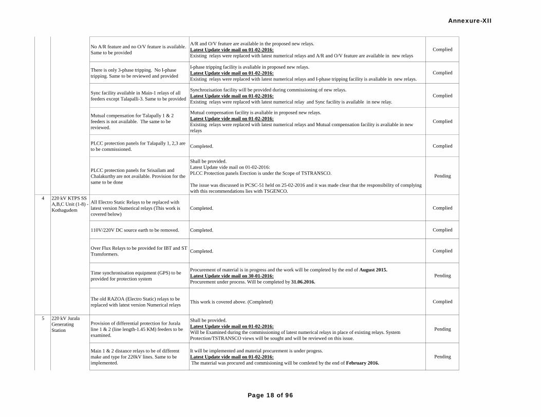
No A/R feature and no O/V feature is available.
Same to be provided
A/R and O/V feature are available in the proposed new relays.
Latest Update vide mail on 01-02-2016:
Existing relays were replaced with latest numerical relays and A/R and O/V feature are available in new relays
Complied
There is only 3-phase tripping. No I-phase
tripping. Same to be reviewed and provided
I-phase tripping facility is avaliable in proposed new relays.
Latest Update vide mail on 01-02-2016:
Existing relays were replaced with latest numerical relays and I-phase tripping facility is avaliable in new relays.
Complied
Sync facility available in Main-1 relays of all
feeders except Talapalli-3. Same to be provided
Synchrozisation facility will be provided during commissioning of new relays.
Latest Update vide mail on 01-02-2016:
Existing relays were replaced with latest numerical relay and Sync facility is available in new relay.
Complied
Mutual compensation for Talapally 1 & 2
feeders is not available. The same to be
reviewed.
Mutual compensation facility is avaliable in proposed new relays.
Latest Update vide mail on 01-02-2016:
Existing relays were replaced with latest numerical relays and Mutual compensation facility is avaliable in new
relays
Complied
PLCC protection panels for Talapally 1, 2,3 are
to be commissioned.Completed. Complied
PLCC protection panels for Srisailam and
Chalakurthy are not available. Provision for the
same to be done
Shall be provided.
Latest Update vide mail on 01-02-2016:
PLCC Protection panels Erection is under the Scope of TSTRANSCO.
The issue was discussed in PCSC-51 held on 25-02-2016 and it was made clear that the responsibility of complying
with this recommendations lies with TSGENCO.
Pending
All Electro Static Relays to be replaced with
latest version Numerical relays (This work is
covered below)
Completed. Complied
110V/220V DC source earth to be removed. Completed. Complied
Over Flux Relays to be provided for IBT and ST
Transformers.Completed. Complied
Time synchronisation equipment (GPS) to be
provided for protection system
Procurement of material is in progress and the work will be completed by the end of August 2015.
Latest Update vide mail on 30-01-2016:
Procurement under process. Will be completed by 31.06.2016.
Pending
The old RAZOA (Electro Static) relays to be
replaced with latest version Numerical relaysThis work is covered above. (Completed) Complied
Provision of differential protection for Jurala
line 1 & 2 (line length-1.45 KM) feeders to be
examined.
Shall be provided.
Latest Update vide mail on 01-02-2016:
Will be Examined during the commissioning of latest numerical relays in place of existing relays. System
Protection/TSTRANSCO views will be sought and will be reviewed on this issue.
Pending
Main 1 & 2 distance relays to be of different
make and type for 220kV lines. Same to be
implemented.
It will be implemented and material procurement is under progess.
Latest Update vide mail on 01-02-2016:
The material was procured and commisioning will be comleted by the end of February 2016.
Pending
3 220 kV N'Sagar
4 220 kV KTPS SS
A,B,C Unit (1-8) -
Kothagudem
5 220 kV Jurala
Generating
Station
Annexure-XII
Page 18 of 96

The inbuilt disturbance recorder available in
numerical relays to be activated
Existing china make relys are going to replacd with indegenius relays in which the Disturbance recorder is available.
Latest Update vide mail on 01-02-2016:
The Material was procured and Existing relays will replace with latest numerical relays, in which the Disturbance
recorder is available. This will be completed by the end of February 2016.
Pending
In adopted distance relay setting for Main 1 &
Main 2 for Jurala Line 1 & 2 one of the settings
of piolet directional protection i.e. PIL -
Dis.resist ROZ is 0.24 ohms whereas
recommended setting is 18.05 hms which is the
major deviation.
It will be corrected.
Latest Update vide mail on 01-02-2016:
It will be corrected. The existing relays are going to replace with latest numerical relays. Latest settings given by
System Protection/TSTRANSCO will be adopted. This will be completed by end of February 2016.
Pending
In bus bar protection settings recommended
setting for charge exit differential is on, whereas
adopted is Off. This is to be reviewed.
It will be reviewed.
Latest Update vide mail on 01-02-2016:
Charge exit Differential is OFF During BUS BAR Testing, and it is made ON.
Complied
Instrument for earth resistance measurement to
be made available
Shall be procured.
Latest Update vide mail on 01-02-2016:
Will be procured.
Pending
DC earth leakage in DC system to be rectified Already rectified Complied
PLCC panel is erected but not commissioned
It will be reviewed.
Latest Update vide mail on 01-02-2016:
Procurement is in advance stage (Order is going to be placed by TSTRANSCO)
The issue was discussed in PCSC-51 held on 25-02-2016 and it was made clear that the responsibility of complying
with this recommendations lies with TSGENCO.
Pending
GPS time synchronisation for 220 kV switch
yard protective relays to be provided
Shall be provided during new relays commissiong.
Latest Update vide mail on 01-02-2016:
GPS is already Procured and Installed. For extending GPS Time Sync to existing relys is under process. Tender
Floated and ordering will be completed by 31.03.2016, work to be completed by end of May 2016.
Pending
S. N Name of
SubstationDetails of work Status of Implementation of Protection Audit Recommendations Remarks
One set of 48 V DC Battery set is available for
PLCC. Another set to be provided.Completed Complied
Separate DG set is not available, but same to be
provided.
Procurement of material is in progress and the work will be completed by the end of August 2015.
Latest Update vide mail on 30-01-2016:
Procurement under process. Will be completed by 30.06.2016.
Pending
Only one set of 48 V DC battery set is available
and another set to be provided. This work is already covered above. (Completed) Complied
2 400 KV KTPP
Switchyard
(Bhupal Pally)
Separate DG set is not available for 400 KV
Switch yard control room. Same to be provided
for reliability.
Procurement of material is in progress and the work will be completed by the end of August 2015.
Latest Update vide mail on 30-01-2016:
Procurement under process. Work will be completed by the end of July 2016.
Pending
5 220 kV Jurala
Generating
Station
Phase II
1 220 KV KTPS SS
A,B,C Unit (1-8) -
Kothagudem
Annexure-XII
Page 19 of 96

1 set of 48 V DC Batteries is only available.
Another set to be provided.
Procurement of material is in progress and the work will be completed by the end of August 2015.
Latest Update vide mail on 30-01-2016:
Battery is under commissioning. Will be completed by the end of Feb-2016.
Pending
Separate DG set is not available for 400 KV
Switch yard control room. Same to be provided
for reliability.
Procurement of material is in progress and the work will be completed by the end of August 2015.
Latest Update vide mail on 30-01-2016:
Procurement under process. Work will be completed by the end of June 2016.
Pending
4 Nagarjunasagar
Main Power
House (220kV)Replacement of Old CB,Las,CTs,CVTs and PTs
etc.
procurment of CTs ,CVTs, CBs and PTs and L A s are under process and shall be replaced with new ones by
29/02/16.
Latest Update vide mail on 01-02-2016:
All old CB's were replaced with new CB's. For LA's PO was Placed. CT's and PT's were procured and available at
site.CT's & PT's will replaced during units shut down period. CVT's were replaced with new CVT's for 2 Feeders and
for remaining 3 Feeders Material were Procured.
Pending
S. N Name of
SubstationDetails of work Status of Implementation of Protection Audit Recommendations Remarks
Power setting is 7.5% instead 20% Pn
(approved) for excess power condenser mode
relay in unit protection. This may be re
examined.
TSGENCO mail received on 14-09-2015:
7.5% EXCESS POWER SETTING IS STILL BEING FOLLOWED.
Latest Update vide mail on 01-02-2016:
The recommended setting of 20% is over 3 Ph rated power, for combined 3 Phases. Where as the settings of 7.5% is
over 3 Ph power, but for single Phase. Hence Combined setting thus would come around 22.5% (7.5 X 3), which is
par with recommendation of 20%.
Pending
It is observed that the time setting knob of Dead
Machine protection Relay is indicating …..
Position instead of 0.5 position. This may be re
examined and rectify same for correction
settings.
TSGENCO mail received on 14-09-2015:
PRESENTLY KNOB POSITION IS CHANGED TO 0.5.Complied
Setting of stub protection function in distance
relay may be re examined as setting varying
from approved and actual.
TSGENCO mail received on 14-09-2015:
ALL APPROVED SETTINGS GIVEN BY SYSTEM PROTECTION DIVSION FOR ALL THE 400KV FEEDER
HAS BEEN ADOPTED FOR BOTH REL670 AND MICOM P442 NUMERICAL RELAYS.
Complied
Timing of Zone-2 Relay setting for Nunnar is
0.5 sec., Mamidapally is 0.6 sec. and VTP-S
earlier it was 0.6 sec. now reconfigured to 0.5
sec. as approved and actual, it may be re
examined
TSGENCO mail received on 14-09-2015:
ALL APPROVED SETTINGS GIVEN BY SYSTEM PROTECTION DIVSION FOR ALL THE 400KV FEEDER
HAS BEEN ADOPTED FOR BOTH REL670 AND MICOM P442 NUMERICAL RELAYS.
Complied
Setting of X IPP. XIPE values of Main-II
Distance relay in phase selection function of
VTPS-1&2 deviation in values from adopted is
observed this may be re examined.
TSGENCO mail received on 14-09-2015:
ALL APPROVED SETTINGS GIVEN BY SYSTEM PROTECTION DIVSION FOR ALL THE 400KV FEEDER
HAS BEEN ADOPTED FOR BOTH REL670 AND MICOM P442 NUMERICAL RELAYS.
Complied
3 400 KV KTPS VI
Switchyard/Palon
cha - Kothagudem
Phase I & Phase-II
1 400 kV Srisailam
LB S/S (Gen)
Annexure-XII
Page 20 of 96

It is observed in all feeders Main-I (REL100)
Relays are available except VTPS-II. This is the
obsolete model and support for taking prints of
settings and Disturbance records etc. It is
recommended for latest version of numerical
relays for better performance and protection
analysis.
Completed Complied
Disturbance recorders (ABB Make Indactic) are
available but not in working condition. These
Disturbance recorders are obsolete model.
Material received at site and Commissioning will be completed by 31/08/15.
TSGENCO mail received on 14-09-2015:
DISTURBANCE RECORDER AND EVENT LOGGER CAN BE TRACED FOR BOTH REL670 (MAIN I) AND
MICOM P442(MAIN II) FOR ALL FEEDERS.
Complied
Event loggers are available but not time
synchronised due to non-availability of GPS
Material received at site and Commissioning will be completed by 31/08/15.
TSGENCO mail received on 14-09-2015:
GPS IS AVAILABLE AND SYNCHRONISED WITH BUSBAR PROTECTION ONLY.
Latest Update vide mail on 01-02-2016:
GPS is Installed and Synchronised with BUS BAR Protection Relays.. For Remaining Relays Tender Floated and
ordering will be completed by 31.03.2016, work to be completed by end of May 2016.
Pending
Bus bar is having static Relay. This may be
examined for numerical graphical representation
with time resolution up to milli sec. related to
the disturbances.
Completed Complied
Generator Protection id displaying only fault
data records, but no graphical representation
with time resolution upto milli sec. related to
the disturbances.
TSGENCO mail received on 14-09-2015:
DR IS NOT AVAILABLE.
Latest Update vide mail on 01-02-2016:
AREVA Make LGPG111 type Relay employed for which
DR IS NOT AVAILABLE. However the same will be taken care during next replacement.
Pending
No relays are synchronised due to non-
availability of GPS.
Material is already available and .Commissioning will be completed by 30/08/15.
TSGENCO mail received on 14-09-2015:
GPS IS AVAILABLE AND SYNCHRONISED WITH BUSBAR PROTECTION ONLY.
Latest Update vide mail on 01-02-2016:
GPS IS AVAILABLE AND SYNCHRONISED WITH BUSBAR PROTECTION. For Remaining Relays Tender
Floated and ordering will be completed by 31.03.2016, work to be completed by end of May 2016.
Pending
Condition monitoring of LA's through
measurement of leakage current may be carried
out.
TSGENCO mail received on 14-09-2015:
Leakage currents are being monitored periodically and are found satisfactory.Complied
1 400 kV Srisailam
LB S/S (Gen)
Annexure-XII
Page 21 of 96
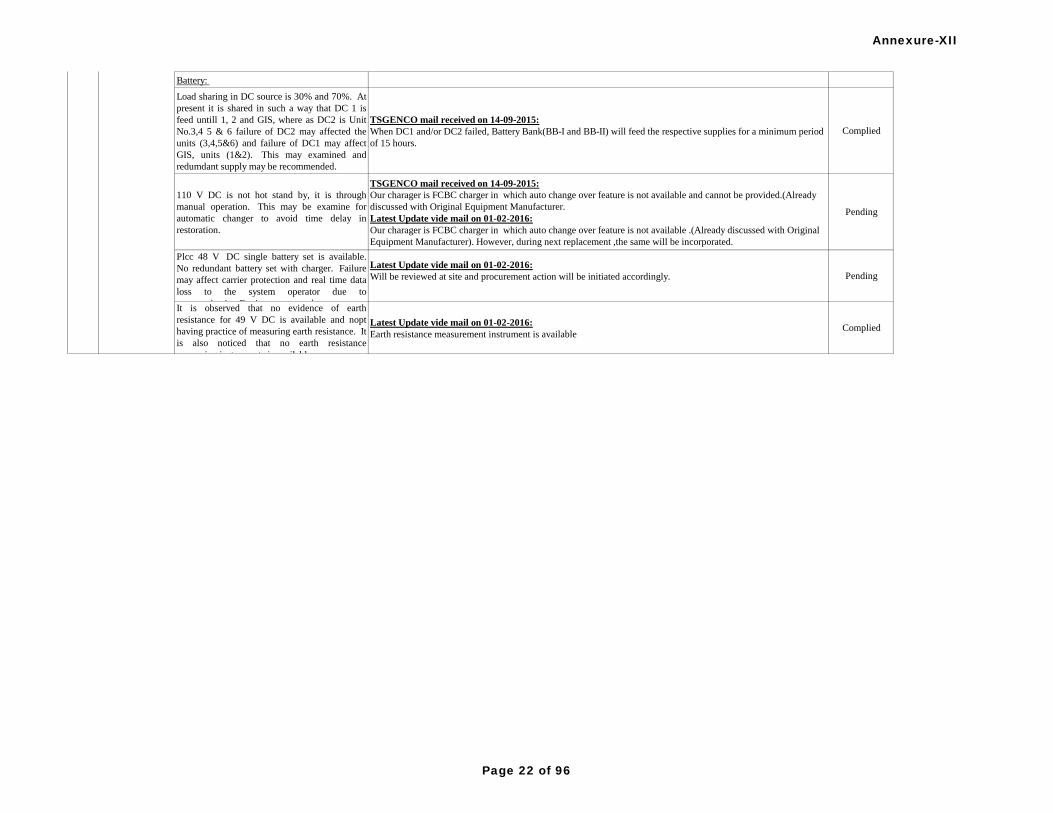
Battery:
Load sharing in DC source is 30% and 70%. At
present it is shared in such a way that DC 1 is
feed untill 1, 2 and GIS, where as DC2 is Unit
No.3,4 5 & 6 failure of DC2 may affected the
units (3,4,5&6) and failure of DC1 may affect
GIS, units (1&2). This may examined and
redumdant supply may be recommended.
TSGENCO mail received on 14-09-2015:
When DC1 and/or DC2 failed, Battery Bank(BB-I and BB-II) will feed the respective supplies for a minimum period
of 15 hours.
Complied
110 V DC is not hot stand by, it is through
manual operation. This may be examine for
automatic changer to avoid time delay in
restoration.
TSGENCO mail received on 14-09-2015:
Our charager is FCBC charger in which auto change over feature is not available and cannot be provided.(Already
discussed with Original Equipment Manufacturer.
Latest Update vide mail on 01-02-2016:
Our charager is FCBC charger in which auto change over feature is not available .(Already discussed with Original
Equipment Manufacturer). However, during next replacement ,the same will be incorporated.
Pending
Plcc 48 V DC single battery set is available.
No redundant battery set with charger. Failure
may affect carrier protection and real time data
loss to the system operator due to
communication Equipment power loss
Latest Update vide mail on 01-02-2016:
Will be reviewed at site and procurement action will be initiated accordingly. Pending
It is observed that no evidence of earth
resistance for 49 V DC is available and nopt
having practice of measuring earth resistance. It
is also noticed that no earth resistance
measuring instruments is available.
Latest Update vide mail on 01-02-2016:
Earth resistance measurement instrument is availableComplied
1 400 kV Srisailam
LB S/S (Gen)
Annexure-XII
Page 22 of 96
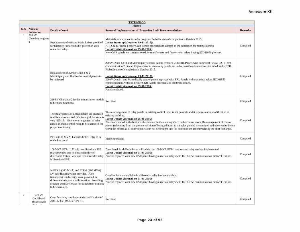
S. N Name of
SubstationDetails of work Status of Implementation of Protection Audit Recommendations Remarks
Replacement of existing Static Relays provided
for Distance Protection, diff protection with
numerical relays
Materials procurement is under progress. Probable date of completion is October 2015.
Latest Status update (as on 09-11-2015):
PTR C& R Panels, Feeder C&R Panels procured and allotted to the substation for commissioning.
Latest Update vide mail on 25-01-2016:
New C&R panels are commissioned for transformers and feeders with relays having IEC 61850 protocol.
Complied
Replacement of 220 kV Dind-1 & 2
Mamidipally and Hial feeder control panels to
be reviewed
220kV Dindi-I & II and Mamidipally control panels replaced with ERL Panels with numerical Relays IEC 61850
communication Protocal. Replacement of remaining panels are under consideration and was included in the DPR.
Probable date of completion is October 2015.
Latest Status update (as on 09-11-2015):
220kV Dindi- I and Mamidipally control panels replaced with ERL Panels with numerical relays IEC 61850
communication Protocol. Feeder C&R Panels procured and allotment issued.
Latest Update vide mail on 25-01-2016:
Panels replaced.
Complied
220 kV Ghanapur-2 feeder annunciation module
to be made functionalRectified Complied
The Relay panels of different bays are scattered
in different rooms and monitoring of the same is
very difficult. Hence re-arrangement of relay
panels in main control room to be examined for
proper monitoring.
The re-arrangement of relay panels in existing control room is not possible and it requires entire modification of
existing building.
Latest Update vide mail on 25-01-2016:
Panels are placed in the best possible manner in the existing space in the control room. Re-arrangement of control
panels (relocating from the present position of being adjacent to the relay panels) is examined and observed to be not
worth the efforts as all control panels can not be brought into the control room accommadating the shift incharges.
Complied
PTR 4 (100 MVA) LV side dir E/F relay to be
made functionalMade functional. Complied
100 MVA PTR-1 LV side non directional E/F
relay provided due to non availability of
directional feature, whereas recommended relay
is directional E/F.
Directional Earth Fault Relay is Provided on 100 MVA PTR-1 and revised relay settings implemented.
Latest Update vide mail on 01-03-2016:
Panel is replaced with new C&R panel having numerical relays with IEC 61850 communication protocol features.Complied
In PTR 1 (100 MVA) and PTR-2 (160 MVA)
LV over flux relays not provided. Also
transformer trouble trips were provided in
differential relay as inbuilt function. Providing
separate auxiliary relays for transformer troubles
to be examined.
Overflux feauters available in differential relay has been enabled.
Latest Update vide mail on 01-03-2016:
Panel is replaced with new C&R panel having numerical relays with IEC 61850 communication protocol features.
Complied
Over flux relay is to be provided on HV side of
220/132 kV, 100MVA PTR-1.Rectified Complied
TSTRANSCO
Phase I
1 220 kV
Chandrayanaghatt
a
2 220 kV
Gachibowli
(hyderabad)
Substation
Annexure-XII
Page 23 of 96

DC earth leakage to be rectified in the 220KV
DC system-I&IIRectified Complied
Replacement of existing Static distance
protection relays for feeders, Differencial relay
of transformers with numerical relays
Materials procurement is under progress. Probable date of completion is October 2015.
Latest Status update (as on 09-11-2015):
PTR panels are procured and allotted. Feeder panels supplies are avaited.
Latest Update vide mail on 25-01-2016:
Panels are procured and alotted to the substation. Commissioning of panels is in progress.
Pending
Different Make and type of distance relays to be
used for Main- & Main-2 protection for Lines.
Same to be implemented
Will be exchanged with new fab city feeder at 400kV SS, Mammidipally.
Latest Update vide mail on 25-01-2016:
Relays of different makes have been procured and retrofitting is in progress.
Pending
220 kV KAMAREDDY line distance relay
settings to be reviewed. As communicated recommended settings are adopted Complied
100MVA PTR-I, O/L Relay settings of HV and
LV side need to be reviewedAs communicated recommended settings are adopted Complied
Replacement of Static type ABB make
Differencial relays (RADSB) provided in, PTR-
1&2 with numerical relays
Materials procurement is under progress.Probable date of completion is October 2015.
Latest Status update (as on 09-11-2015) and vide mail on 25-01-2016:
PTR C & R panels are procured and allotted to the substation for commissioning.
Pending
100MVA PTR-2 OLTC tap position indicator in
RTCC panel to be made functionalRectified Complied
4 220 kV HIAL
Substation Earth leakage to be provided Rectified DC leakage problem Complied
5 220 kV
Malayalapalli S/S-
APTRANSCO Time synchronising system (GPS), Distrubance
Recorder (DR), Event Logger (ER), Synchro
check relay not available in the station.
Materials procurement is under progress.Probable date of completion is October 2015.
Latest Status update (as on 09-11-2015):
PTR panels are procured and allotted. Feeder panels supplies are avaited.
Latest Update vide mail on 25-01-2016:
New C&R panels are procured and allotted. Commissioning is in progress.
Pending
6 220 KV
Shahpurnagar
Substation
Over flux relay is to be provided on HV side of
220/132 kV, 100MVA PTR, 160 MVA PTR 1
& 2.
Rectified. Overflux relays are available on HV side of all 220kV PTRs Complied
2 220 kV
Gachibowli
(hyderabad)
Substation
3 220 kV side of
400/ 220kV
Gajwel Substation
Annexure-XII
Page 24 of 96

Static distance protection relays to be replaced
with numerical relaysAll 220kV feeders are having Numerical relays. Complied
100 MVA PTR-2 remote temperature indicator
to be replacedRemote temperature indicator replaced. Complied
over flux relay to be provided for 100 MVA
PTR-1Overflux relay available in differential relay has been enabled. Complied
DC earth leakage to be rectified in 220KV DC-I
systemRectified Complied
Different Make and type of distance relays to be
used for Main- & Main-2 protection for 220 KV
mamidipally & Gachibowli lines Lines. Same to
be implemented
Rectified
Latest Update vide mail on 25-01-2016:
New panels are procured and allotted. Replacement of PTR panels completed and replacement feeder panels will be
completed as and when relay settings are communicated and shut down on the feeders is avaialble.
Latest Update vide mail on 01-03-2016:
New panels are procured and allotted.
1) Replacement of PTR panels is completed and commissioned.
2) New Feeder C&R panels are available at the Sub-station and will be commissioned shortly.
Pending
Static differential and distance protection relays
to be replaced with numerical relays
Materials procurement is under progress. Probable date of completion is October 2015.
Latest Status update (as on 09-11-2015):
PTR C& R Panels, Feeder C&R Panels procured and allotted to the substation for commissioning.
Latest Update vide mail on 25-01-2016:
New panels are procured and allotted. Replacement of PTR panels completed and replacement feeder panels will be
completed as and when relay settings are communicated and shut down on the feeders is avaialble.
Latest Update vide mail on 01-03-2016:
New panels are procured and allotted.
1) Replacement of PTR panels is completed and commissioned.
2) New Feeder C&R panels are available at the Sub-station and will be commissioned shortly.
Pending
Overflux protection to be provided for
100MVA PTR-I, LV over flux is removed.
Overflux features available in differential relay has been enabled.
Latest Update vide mail on 25-01-2016:
New panels are procured and allotted. Replacement of PTR panels completed and replacement feeder panels will be
completed as and when relay settings are communicated and shut down on the feeders is avaialble.
Latest Update vide mail on 01-03-2016:
New panels are procured and allotted.
1) Replacement of PTR panels is completed and commissioned.
2) New Feeder C&R panels are available at the Sub-station and will be commissioned shortly.
Pending
100MVA PTR-III Existing LV directional earth
fault relay is to be made functional
Made functional.
Latest Update vide mail on 25-01-2016:
New panels are procured and allotted. Replacement of PTR panels completed and replacement feeder panels will be
completed as and when relay settings are communicated and shut down on the feeders is avaialble.
Pending
100MVA PTR-III HV directional earth fault
relay is to be made functional
Made functional.
Latest Update vide mail on 25-01-2016:
New panels are procured and allotted. Replacement of PTR panels completed and replacement feeder panels will be
completed as and when relay settings are communicated and shut down on the feeders is available.
Latest Update vide mail on 01-03-2016:
New panels are procured and allotted.
1) Replacement of PTR panels is completed and commissioned.
2) New Feeder C&R panels are available at the Sub-station and will be commissioned shortly.
Pending
8 220 kV
Shivarampally
Substation
7 220 kV
Shamshabad
Substation
Annexure-XII
Page 25 of 96

LV over flux protection in 100 MVA, PTR-II to
be made available.
Overflux relay available in differential relay has been enabled.
Latest Update vide mail on 25-01-2016:
New panels are procured and allotted. Replacement of PTR panels completed and replacement feeder panels will be
completed as and when relay settings are communicated and shut down on the feeders is available.
Latest Update vide mail on 01-03-2016:
New panels are procured and allotted.
1) Replacement of PTR panels is completed and commissioned.
2) New Feeder C&R panels are available at the Sub-station and will be commissioned shortly.
Pending
DC earth fault in 220V DC system to be
rectifiedRectified Complied
220 kV Bus bar protection relay along with in-
built LBB function to be made functional220KV busbar protection scheme kept in service. Complied
Replacement of static differential protection and
distance protection relays with numerical relay
Materials procurement is under progress.Probable date of completion is October 2015.
Latest Status update (as on 09-11-2015):
PTR C& R Panels, Feeder C&R Panels procured and allotted to the substation for commissioning.
Latest Update vide mail on 25-01-2016:
New C&R panels are procured and allotted. Commissioning is in progress.
Pending
Provision of overflux protection for
transsformersProvided. Complied
100 MVA, PTR-III Earth fault relay Time
setting for HV and LV side to be reviewedAs communicated recommended settings are adopted in the field. Complied
160MVA, PTR-II HV O/L and E/F relays to be
made functional. LV side E/F relay to be made
functional.
HV O/L, E/F relays are replaced with ER make AUGUS-II type relay. Complied
O/L & E/F setting of transformers to be
reviewedAs communicated recommended settings are adopted in the field. Complied
220 kV Gachibowli line Main-II distance relay
is be made functional(At present feeder name
changed as Shankarpally-II)
Defective Main-II relay was replaced with GE make,Type LPS-D relay. Complied
Zone-III setting in Shadnagar feeder to be
reviewedZone-III settings are changed as per the instructions of Power Systems Wing. Complied
Zone-III Timing setting in Shamshabad-II to be
reviewed.Recommended settings are adopted Complied
Replacement of PLCC panels of 400 kV
Ramagundam line to be done
Latest Update vide mail on 25-01-2016:
Under PGCIL Scope. PGCIL authories have informed that the panels will be replaced soon as their indent for
material is under process.
The issue was discussed in PCSC-51 held on 25-02-2016 and it was made clear that the responsibility of complying
with this recommendations lies with TSTRANSCO.
Pending
8 220 kV
Shivarampally
Substation
9 220 kV
Yeddumailaram
Substation
10 400kV side of
400/ 220 kV
Gajwel Substation
Annexure-XII
Page 26 of 96

315 MVA ICT-1 O/L relay setting of HV & LV
side to be reviewedRecommended settings are adopted Complied
Distance protection relay setting to be reviewed Recommended settings are adopted Complied
315 MVA ICT-2 OLTC tap position indicator in
RTCC panel is to be made functionalRectified. Tap Position indication is functioning. Complied
Procurement of testing kit for testing switchyad
equipment Tan delta and universal relay testing kit allotted Complied
Replacement of Static differencial protection
relays provided for ICT-1&2 with numerical
relays.
Materials procurement is under progress.
Latest Status Updated (as on 03-07-2015):
Materials procurement is under progress.Probable date of completion is October'2015.
Latest Status update (as on 09-11-2015) and vide mail on 25-01-2016:
PTR C & R panels are procured and allotted to the substation for commissioning.
Latest Update vide mail on 01-03-2016:
Numerical differential relays procurement is in progress and static relays will be replaced as and when supplies are
received.
Pending
10 400kV side of
400/ 220 kV
Gajwel Substation
Annexure-XII
Page 27 of 96

protection settings for relays to be reviewed Protection settings are reviewed and adopted settings are as per APTRANSCO protection philosophy. Complied
Station Event logger to be made available Station E/L made available Complied
Analog meters & temperature indicators to be
replaced with Digital Meters
Materials procurement is under progress.
Latest Update vide mail on 25-01-2016:
Materials procurement is under progress.
Pending
Review of distance protection setting of
transmission lines
Protection settings are reviewed and adopted settings are as per APTRANSCO protection philosophy.
Latest Update vide mail on 25-01-2016:
Protection settings are reviewed and adopted settings are as per APTRANSCO protection philosophy.
Complied
Replacement of Static Relay like differential
relay (RADSB) of ICT01, Bus bar protection
relay (RADSS) with numerical relay
Materials procurement is under progress.Probable date of completion is October 2015.
Latest Status update (as on 09-11-2015):
PTR C & R panels are procured and allotted to the substation for commissioning.
Latest Update vide mail on 25-01-2016:
Numerical differential relays procurement is in progress and static relays will be replaced as and when supplies are
received.
Latest Update vide mail on 01-03-2016:
400KV Busbar protection relay is replaced with SIEMENS make relay and commissioned.
Numerical differential relays procurement is in progress and static relays will be replaced as and when supplies are
received.
Pending
Adopted relay setting in 400 kV Line distance
relays, differential and O/C & E/F relay in ICT-3
is to be reviewed
Adopted as per approved settings. Complied
DEF function in distance protection is found not
enabled which is to be enabled/ activatedDEF functioning is activated. Complied
Dead time for Raichur Tie CB for A/R function
is set to 2 sec instead of 1 sec. same to be
rectified
Dead Time Setting Changed. Complied
11 400 kV
Mamidipally &
220 kV
Mamidipally
substation
12 400 kV
Mehboobnagar
Substation
Distance protection relays for 400 kV and 220
kV feeders to be replaced with numerical relays
Materials procurement is under progress.Probable date of completion is October 2015.
Latest Status update (as on 09-11-2015):
New relays for replacement of old ones in 400kV feeder C & R Panels are procured for Main-I schemes and allotted
for commissioning.
Latest Update vide mail on 25-01-2016:
Numerical distance relays have been procured and allotted for retrofitting in 400 KV system. New C&R panels
procured for 220 KV system could not be utilised in this substation as their architecture can support only double bus
system and not the double bus with transfer bus system available in this substation. New panels with revised
specification is in progress and will be commissioned as and when supplies are received.
Latest Update vide mail on 01-03-2016:
As the allotted Panels are not as per the requirement of Mamidipally SS. New Panels with Double bus with Transfer
Bus system procurement is in progress and will be commissioned as and when supplies are received.Allottted panels
are diverted to other Substations where they are suitable.
Pending
Annexure-XII
Page 28 of 96

Event logger in Micro SCADA needs to be
properly configured. Also existing ABB make
event logger is learnt to be not communicating
with relay other than ABB make and also with
ABB make REL316 relay. Hence upgrading the
event logger to be done
New Event Logger and SIEMENS SCADA RTU Panels Commissioned Complied
ABB make distance relay of Type REL 316 to
be replaced
Materials procurement is under progress.
Latest Status update (as on 09-11-2015):
New relays for replacement of old ones in 400kV feeder C & R Panels are procured for Main-I schemes and allotted
for commissioning.
Latest Update vide mail on 25-01-2016:
Numerical distance relays have been procured and allotted for retrofitting in 400 KV system
Pending
Overflux relay setting of ICT-1 on HV side to be
reviewedO/F Setting is adopted as per approved settings. Complied
Synchronising panel to be made functional Functioning. Complied
PLCC protection codes to be tested for Raichur-
Veltoor line Carrier protection equipment available and working (PGCIL scope) Complied
S. N Name of
Substation Details of work Status of Implementation of Protection Audit Recommendations Remarks
Providing carrier aided tripping for 220 kV
feeders to be examined.Carrier aided tripping for all 220kV feeders connected to 400kV sub-stations. Complied
Providing of 2 Nos. DC sources as group-1 and
group-2 protections to be examined for reliable
protection.
2nd DC source for group 1 & 2 protection phylosophy will be adopted while commissioning new panels.New C&R
panels are under procurement. Probable date of completion is October 2015.
Latest Status update (as on 09-11-2015):
New C&R panels procured and allotment issued. 2nd DC source for Group-1 & 2 protection philosophy will be
adopted while commissioning new panels.
Latest Update vide mail on 25-01-2016:
Two DC sources are avaialble. New C&R panels are commissioned with Group-1&2 DC source protection
phylosophy.
Complied
Metal spreading in switchyard was not done.
The same to be taken up.Metal spreading work completed. Complied
Carrier aided protection scheme has to be
implemented.Carrier Protection is provided for 220kV feeders Shankarpally-I&II emanating from 400kV Shankarpally. Complied
Utilising the two DC sources available for all
the control and relay panels to be examined.
2nd DC source for group 1 & 2 protection phylosophy will be adopted while commissioning new panels.New C&R
panels are under procurement. Probable date of completion is October 2015.
Latest Status update (as on 09-11-2015) and vide mail on 25-01-2016:
New C&R panels procured and allotment issued. 2nd DC source for Group-1 & 2 protection philosophy will be
adopted while commissioning new panels.
Pending
2 220kV
Gachibowli S/S
12 400 kV
Mehboobnagar
Substation
Phase II
1 220 KV
Chandrayanagutta
Annexure-XII
Page 29 of 96

Metal spreading in switchyard is not available. Estimate is under preparation. Pending
Carrying out overhauling of 160 MVA PTRE-II
(Siemens) HV Breaker (BHEL) to be examined
since overhauling is not done from the date of
commissioning, i.e. on 04.02.1991.
Purchase Order placed for Breaker spares.Yet to be received from BHEL.
Latest Status update (as on 09-11-2015):
Purchase Order placed for Breaker spares.Yet to be received from BHEL.Breaker operations are being checked
periodically and found to be satisfactory.
Latest Update vide mail on 25-01-2016:
Breaker operations are being checked periodically and found to be satisfactory.
Complied
Carried aided protection is not provided for 220
kV Lines. Providing the same to be examined.Implemented. Complied
Providing two DC sources for DC system to be
examined.
Under examination and indent for providing second DC source is under prepration.
Latest Update vide mail on 25-01-2016:
2 Nos. DC sources of 200 AH each are available in the substation. Group-I&2 protection phylosophy is being
adopted while commissioning new panels (work is in progress).
Complied
Bus bar protection is not available and in turn
there is no LBB protection for circuit breakers.
Bus bar panel are under procurement and probable date of completion is October 2015 as they are in DPR for R&U
of Protection in TSTRANSCO for which PSD funding is awaited.
Latest Status update (as on 09-11-2015):
Bus bar panel are under procurement and probable date of completion is December 2015 as they are in DPR for
R&U of Protection in TSTRANSCO for which PSD funding is awaited.
Latest Update vide mail on 25-01-2016:
Bus bar Panal will be commissioned as and when the panels, for which orders are already placed, are recevied.
Pending
Only one set of 220 v battery bank is available.
Under examination and indent for providing second DC source is under prepration.
Latest Update vide mail on 25-01-2016:
2nd DC source will be provided as and when supplies are recevied.
Pending
5 220KV
Shahpurnagar ss -
APTRANSCOCarrier aided protection scheme has to be
implemented.
Projected in DPR, awaiting budget.
Latest Update vide mail on 25-01-2016:
Procurement of communication equipment with PSD Funding is under progress.
Pending
Implementation of carrier aided protection
scheme to be examined.Carrier aided tripping for all 220kV feeders connected to 400kV sub-stations. Complied
Utilising the two DC sources available for all
the control and relay panels to be examined.
2nd DC source for group 1 & 2 protection phylosophy will be adopted while commissioning new panels.New C&R
panels are under procurement. Probable date of completion is October 2015.
Latest Status update (as on 09-11-2015):
2nd DC source for group 1 & 2 protection phylosophy will be adopted while commissioning new panels.New C&R
panels are procured and allotted for commissioning.
Latest Update vide mail on 25-01-2016:
Group-I&2 protection phylosophy is being adopted while commissioning new panels (work is in progress).
Pending
Diesel set has to be commissioned. Commissioned. Complied
3 220 kV Ghanapur
SS
4 220 kV
Shamshabad S/S -
APTRANSCO
6 220kV
Shivarampally S/S
7 220 kV Tandur,
Rangareddy -
APTRANSCO
Annexure-XII
Page 30 of 96

APTRANSCO should have two independent
DC sources to the protection and switchgears
and one source should be for back up.
2nd DC source for group 1 & 2 protection phylosophy will be adopted while commissioning new panels.New C&R
panels are under procurement. Probable date of completion is October 2015.
Latest Status update (as on 09-11-2015):
2nd DC source for group 1 & 2 protection philosophy will be adopted while commissioning new panels.New C&R
panels for PTRs allotted for commissiong and supplies for feeder C&R panels are awaited.
Latest Update vide mail on 25-01-2016 & 01-03-2016:
2nd DC source will be provided as and when supplies are recevied and Group-I&2 protection phylosophy will be
restored as all the new panels are being commissioned keeping this aspect in view.
Pending
Carrier aided protection scheme has to be
implemented.Carrier aided tripping for all 220kV feeders connected to 400kV sub-stations. Complied
7 220 kV Tandur,
Rangareddy -
APTRANSCO
Annexure-XII
Page 31 of 96

Carrier aided protection is not implemented for
some of the 220 kV feeders.
Carrier aided protection is implemented for 220kV Shamshabad, Shadnagar, Sivarampally, Chandrayangutta and
HAIL-I&II feeders.Complied
Closed circuit cameras to be arranged at
strategic points inside the switchyard as well as
along the fencing of the substation to monitor
any critical situation insie and to keep vigilance
on outside elements for taking view of changing
security threat perceptions to substation.
Providing of CCTV Cameras is under consideration.
Latest Update vide mail on 25-01-2016:
Providing of CCTV Cameras is under consideration.
Pending
9 220 kv side of
400/ 220 kV
Gajwel SS
Carrier aided protection scheme implementation
to be examined.Carrier aided protection scheme commisioned. Complied
Implementation of carrier aided protection
scheme to be examined.Carrier protection is provided towards Shankarpally-I & II feeders Pending
providing second DC sources for all the control
and relay panels to be examined for better
reliability.
2nd DC source for group 1 & 2 protection phylosophy will be adopted while commissioning new panels.New C&R
panels are under procurement. Probable date of completion is October 2015.
Latest Status update (as on 09-11-2015) and vide mail on 25-01-2016:
New C&R panels procured and allotment issued. 2nd DC source for Group-1 & 2 protection philosophy will be
adopted while commissioning new panels.
Pending
Metal sprading is not found in 220 kV S/S yard
& 132 kV yard.
Will be considered after completion of phase-I works.
Latest Update vide mail on 25-01-2016:
Is under active consideration as many other substations have been provided with metal spreading in the recent past.
Pending
Cable Trench is not provided in 220 kV
Gachibowli, 100MVA PTR-II and B/C.
Work is under progress.
Latest Update vide mail on 25-01-2016:
Cable trench construction will be carried out along with metal spreading work.
Pending
Providing of dedicated feeder for AC Aux.
Supply to be examined.
Work is under progress
Latest Update vide mail on 25-01-2016:
Work is under progressPending
Carried aided protection is not provided for 220
kV Lines. Carrier aided protection scheme commisioned. Complied
Providing Reactor at 400 kV bus to be
examined.
Estimates are under preparation
Latest Status update (as on 09-11-2015) and vide mail on 25-01-2016:
125 MVAR ,400kV Reactor procurement is under progress. Probable date of completion is June,2016.
Pending
Carrier protection to be provided for 220kV
lines
Protection Couplers procurement is under progress.
Latest Update vide mail on 25-01-2016:
Protection Couplers procurement is under progress.
Pending
10 220kV
Yeddumailaram
S/S
11 400 KV
Mahaboobnagar
12 400kV Dichipalli,
8 400 kV
Mamidipally ss &
220 kV
Mamidipally ss -
APTRANSCO
Annexure-XII
Page 32 of 96

Dedicated supply to be made available
Under examination
Latest Status update (as on 09-11-2015):
At present 2 Nos. 33kV feeders are available for station supply. Dedicated supply is under examination.
Latest Update vide mail on 25-01-2016:
At present 2Nos.33KV feeders are availbale for station supply. Informed TSNPDCL (Distribution Company) to take
up the work immediately.
Pending
Sl.
No.Name of
SubstationDetails of Protection Audit observation Action taken to attend the observation Remarks
1 400kV NTPC
Ramagundam
Station (Gen)Distrubance Recorders (ABB, INDACTIC) not
having GPS time synchronisation (for 400 kV
Warangal Line, 400 kV Gajwel Line, 400 kV
Malkaram Line, 400 kV Hyderabad Line # 3,
400 kV Hyderabad Line # 4), 400 kV Dichipalli
Numerical relay (DR) not having GPS time
synchronisatiion.
Time synch is yet to be provided for 400 kV Dichipalli Numerical relay (DR) Pending
S. No Name of
SubstationDetails of work Status of Implementation of Protection Audit Recommendations Remarks
Dead Earth fault in 220 V DC set 1 & 2. Completed Complied
relays not Synchronised with GPS.
The work will be completed by March 2015.
Latest Update as on 25-08-2015:
GPS received at site. The work will be completed by December 2015.
Latest Update vide mail on 27-01-2016:
Completed.
Complied
A/R Scheme for 220 kV Lines not available for
lines.Completed Complied
2 220 kV Kadra
(Gen) Carrier protection is out of service for Karwar 1
& 2 feedersCompleted Complied
3 220 kV Kodasalli
S/S (Gen) Carrier protection is not in service for all feeders
(the real time testing is pending).Completed Complied
4
220 kV Nagjhari
Power House
The LBB relay time & current are sdet at 1.5 sec
& 0.2 A for all feeders and generating
transformers.
Completed Complied
220 V DC earth fault persisting negative dead
grounded
Latest Update as on 25-08-2015:
Negative dead ground is removed. Partial ground is present. The work will be completed by December 2015.
Latest Update vide mail on 27-01-2016:
Completed
Complied
12 400kV Dichipalli,
5 220 kV Raichur
TPS
KPCL
Phase-I
1 220 kV BTPS
Combined (Phase-I & Phase-II)
Annexure-XII
Page 33 of 96

LBB Relay RAICA RXKL1 setting for ICT-II is
kept at 50 mA.Completed Complied
LBB relay timing is observed to be 0.7 sec
which is high, can be reduced to 250 to 300
m.sec in coordination with pole discrepancy
relay of breaker.
Completed Complied
Feeders with same Make & Type relay as Main-I
& Main-II should be changed with different
Make/Type relays for Main-I & Main-II.
LOA issued to M/s Alstom T&D India Ltd. Bengaluru. The work will be completed by December - 2015.
Latest Update as on 25-08-2015:
LOA dtd. 15.12.2014 issued to M/s Alstom T&D India Ltd. Bengaluru. Review of drawings completed. Materials
received at site. The work will be completed by December - 2015.
Latest Update vide mail on 27-01-2016:
LOA dated: 15.12.2014 issued to M/s Alstom T&D India Ltd. Bengaluru. Erection work completed for all 8 Lines &
2 BCs except for S-2 line, which is in pregress.The erection works involve obtaining prior line clearance from the
State Load Dispatch Centre hence the erection work for remaining line is expected to complete by 31.01.2016.
Pending
Feeders having O/C and E/F relays as Main-II to
be replaced with distance relays for good
protection coordination on 220 kV Grid.
LOA issued to M/s Alstom T&D India Ltd. Bengaluru. The work will be completed by December - 2015.
Latest Update as on 25-08-2015:
LOA dtd. 15.12.2014 issued to M/s Alstom T&D India Ltd. Bengaluru. Review of drawings completed. Materials
received at site. The work will be completed by December - 2015.
Latest Update vide mail on 27-01-2016:
LOA dated: 15.12.2014 issued to M/s Alstom T&D India Ltd. Bengaluru. Erection work completed for all 8 Lines &
2 BCs except for S-2 line, which is in pregress.The erection works involve obtaining prior line clearance from the
State Load Dispatch Centre hence the erection work for remaining line is expected to complete by 31.01.2016.
Pending
Carrier protection should be kept in service for
the feeders having no carrier protection.
The work will be completed by July - 2015.
Latest Update as on 25-08-2015:
Completed
Complied
DC earth leakage should be arrested on top
priority to avoid spurious trippings due to DC
earth leakage.
Completed Complied
Substation GPS to be connected to event logger
and protection relays for correct recording of the
sequence of events.
e-NIT floated on 15.09.2014. The work will be completed by December-2015.
Latest Update as on 25-08-2015:
NIT was issued through e-portal. LOA for Supply & Erection of Disturbance Recorder & GPS issued to M/s Alstom
T&D India Ltd., Chennai on 26.06.2015. Contract agreement executed.
Latest Update vide mail on 27-01-2016:
Letter of Award issued to M/s Alstom T&D India Ltd., Chennai for Supply & Erection of Disturbance Recorder &
GPS on 26.06.2015. The firm has completed site visit for collection of data’s from site and is now preparing
schematic drawings.It is estimated that the work completion period may extend until 30.12.2016.
Pending
5 220 kV Raichur
TPS
6 220 kV
Sharavathi SS
(Gen)
Annexure-XII
Page 34 of 96

High setting for the bus bar differential
protection i.e. 325 V.
The work will be completed by March - 2015.
Latest Update as on 25-08-2015:
Assistance of OEM required. OEM opined that the setting is in line with latest fault levels, considering fault level as
50kA.
Latest Update vide mail on 27-01-2016:
Assistance of OEM required. OEM opined that the setting is in line with latest fault levels, considering fault level as
50kA. This shall be reviewed as per the opinion of OEM and hence may please be removed from the list.
Complied
A/R Selection switch is kept in non auto mode
for all 400 kV lines.
A/R function for 400kV lines shall be completed by May 2015.
Latest Update as on 25-08-2015:
Timers dispatched from supplier. Software programming is completed during previous shut down availed on lines.
One more shut down is required for uploading settings and to modify wiring. A/R function for 400kV lines shall be
completed by December 2015.
Latest Update vide mail on 27-01-2016:
Request sent to State Load Despatch Centre for availing LC for enabling A/R function for 400kV lines.The erection
works involve obtaining prior line clearance from the Sate Load Dispatch Centre hence the work completion period
may extend till 30.03.2016
Pending
Dead 220 V DC Earth fault for both sets i.e.
Positive to Earth 235 V.Completed Complied
GPS time synchronisation for all the relays &
DR not carried.
The work will be completed by May 2015.
Latest Update as on 25-08-2015:
GPS received at site. The work will be completed by December 2015.
Latest Update vide mail on 27-01-2016:
Completed.
Complied
Pole descripency relay setting kept at 0.1 Sec for
all the lines.
The work will be completed by July - 2015.
Latest Update as on 25-08-2015:
Timers dispatched from supplier. The work will be completed by December - 2015.
Latest Update vide mail on 27-01-2016:
Completed.
Complied
220 V DC earth fault persisting with leakage
current of 15 mACompleted Complied
PD settings for Munirabad, BTPS and
Mahboobnagar kept at 0.1 secCompleted Complied
RTPS-Munirabad line Zone-II setting (26.880
Ohm) is more than Zone-III (26.44 Ohm)Completed Complied
7 400 kV BTPS
8 400 kV Raichur
TPS SS (IS)
Annexure-XII
Page 35 of 96

No fault locator working for Munirabad and
Mehboobnagar lines
The order placed on M/s.Siemens to replace relays. The work will be completed by May - 2015.
Latest Update as on 25-08-2015:
Order placed on M/s Siemens for retrofitting of electromechanical relays with Numerical relays for both the lines.
The retrofitting of electromechanical relays with Numerical version for Munirabad line has been completed. The
fault locator is incorporated in numerical Relays. Retrofitting work for Mehaboobnagar line is pending. Awaiting for
line shutdown.
Latest Update vide mail on 27-01-2016:
Completed.
Complied
DR communication is not working for
Munirabad and Mehboobnagar lines
The order placed on M/s.Siemens to replace relays. The work will be completed by May - 2015.
Latest Update as on 25-08-2015:
Order placed on M/s Siemens for retrofitting of electromechanical relays with Numerical relays for both the lines.
Inspection of material completed. The retrofitting of electromechanical relays with Numerical version for Munirabad
line has been completed. The fault locator is incorporated in numerical Relays. Retrofitting work for Mehaboobnagar
line is pending. Awaiting for line shutdown.
Latest Update vide mail on 27-01-2016:
Completed.
Complied
Time Synchronisation for all relays.EL & DR
are done with GPS.The order placed on M/s.Siemens to replace relays. The work will be completed by May - 2015. Pending
Name of
SubstationDetails of work Status of Implementation of Protection Audit Recommendations Remarks
Karwar 1 & 2 fereders have only R Ph CVT
available (Y and B Ph CVTs are not available).
NIT issued vide no. LOT/CEED/EE4/245kV CVT/1285 Dated: 17.07.2014. Tender finalisation will be completed by
March - 2015.The work will be completed by December - 2015.
Latest Update as on 25-08-2015:
Purchase order dtd 27.04.2015 placed on M/s Siemens ltd. Chennai. Review of technical drawings completed and
are approved. Inspection is in progress.
Latest Update vide mail on 27-01-2016:
Purchase order dated: 27.04.2015 placed on M/s Siemens ltd. Chennai. Supply of all Materials after inspection at
firms work completed. Erection work may take 2 weeks after handing over of a line bay. However, the erection work
involves obtaining prior line clearance from the State Load Dispatch Centre and it is estimated that the work
completion period may extend until 30.12.2016.
Pending
8 400 kV Raichur
TPS SS (IS)
Phase-II
220 kV Kadra
(Gen)
1
Annexure-XII
Page 36 of 96

For Kaiga and Kodasalli feeders have only R &
B CVTs available. (Y Ph CVT not available)
NIT issued vide no. LOT/CEED/EE4/245kV CVT/1285 Dated: 17.07.2014. Tender finalisation will be completed by
March - 2015. The work will be completed by December - 2015.
Latest Update as on 25-08-2015:
Purchase order dtd 27.04.2015 placed on M/s Siemens ltd. Chennai. Review of technical drawings completed and
are approved. Inspection is in progress.
Latest Update vide mail on 27-01-2016:
Purchase order dated: 27.04.2015 placed on M/s Siemens ltd. Chennai. Supply of all Materials after inspection at
firms work completed. Erection work may take 2 weeks after handing over of a line bay. However, the erection work
involves obtaining prior line clearance from the State Load Dispatch Centre and it is estimated that the work
completion period may extend until 30.12.2016.
Pending
Double earthing of all the supporting
structures/elements is to be ensured and neutral
of generting transformers and LAs should be
exclusively earthed.
The work will be completed by July 2015.
Latest Update as on 25-08-2015:
Work order issued. Work is under progress. The work will be completed by December 2015.
Latest Update vide mail on 27-01-2016:
Since Kodasalli is a dam based project, double earthing of ODY structures in the existing concrete area of switchyard
could not be assessed. Work Order issued has been cancelled and NIT re-floated. The work will be completed by
30.06.2016.
Pending
2 220 kV Kodasalli
S/S (Gen)
Work order placed for Servicing of all 89T Transfer Bus isolators and Bus Coupler breaker. Wiring Work completed
partly. Letter addressed to OEM for detailed cable schedule and all the connected works.The work will be completed
by August 2015.
Latest Update as on 25-08-2015:
Servicing of all the 89T isolator & Bus coupler breaker carried out and kept ready. Also, action is being taken to
replace the faulty 220kV CT of Y-phase Bus coupler. Work order placed for procurement of CT's and auxiliaries.
The work will be completed by December 2015.
Latest Update vide mail on 27-01-2016:
CT’s required for commission of bus coupler. Purchase order dated: 27.04.2015 placed on M/s Alstom ltd.
Bengaluru for procurement of CTs. Drawings approved and manufacturing clearance issued. Inspection call by Firm
is awaited. Erection work may take 2 weeks after handing over of Line bay. There are 13 Line bays. However, the
erection works involve obtaining prior line clearance from the State Load Dispatch Centre and Expected work
completion date: 30.12.2016.
Pending
Bus coupler and transfer bus are out of service,
bus coupler module on busbar protection panel
is kept out of service.
Work order placed for Servicing of all 89T Transfer Bus isolators and Bus Coupler breaker. Control wiring works
pending due to nonavailability of cable ICS at site. Letter addressed to OEM for detailed cable schedule and all the
connected works. BUS COUPLER module will be put into service during commissioning. The work will be
completed by August 2015.
Latest Update as on 25-08-2015:
Wiring work completed partly. Work order placed for procurement of CT's and auxiliaries. The work will be
completed by December 2015.
Latest Update vide mail on 27-01-2016:
CT’s required for commission of bus coupler. Purchase order dated: 27.04.2015 placed on M/s Alstom ltd.
Bengaluru for procurement of CTs. Drawings approved and manufacturing clearance issued. Inspection call by Firm
is awaited. Erection work may take 2 weeks after handing over of Line bay. There are 13 Line bays. However, the
erection works involve obtaining prior line clearance from the State Load Dispatch Centre and Expected work
completion date: 30.12.2016
Pending
Bus coupler and transfer bus are out of service,
bus coupler module on busbar protection panel
is kept out of service.
220 kV Kadra
(Gen)
1
Annexure-XII
Page 37 of 96
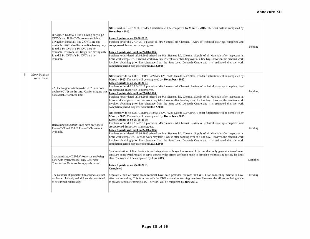
220 kV Nagjhari-Ambewadi 1 & 2 lines does
not have CVTs on the line. Carrier tripping was
not available for these lines.
NIT issued vide no. LOT/CEED/EE4/245kV CVT/1285 Dated: 17.07.2014. Tender finalisation will be completed by
March - 2015. The work will be completed by December - 2015.
Latest Update as on 25-08-2015:
Purchase order dtd 27.04.2015 placed on M/s Siemens ltd. Chennai. Review of technical drawings completed and
are approved. Inspection is in progress.
Latest Update vide mail on 27-01-2016:
Purchase order dated: 27.04.2015 placed on M/s Siemens ltd. Chennai. Supply of all Materials after inspection at
firms work completed. Erection work may take 2 weeks after handing over of a line bay. However, the erection work
involves obtaining prior line clearance from the State Load Dispatch Centre and it is estimated that the work
completion period may extend until 30.12.2016.
Pending
Remaining six 220 kV lines have only one R-
Phase CVT and Y & B Phase CVTs are not
available.
NIT issued vide no. LOT/CEED/EE4/245kV CVT/1285 Dated: 17.07.2014. Tender finalisation will be completed by
March - 2015. The work will be completed by December - 2015.
Latest Update as on 25-08-2015:
Purchase order dtd 27.04.2015 placed on M/s Siemens ltd. Chennai. Review of technical drawings completed and
are approved. Inspection is in progress.
Latest Update vide mail on 27-01-2016:
Purchase order dated: 27.04.2015 placed on M/s Siemens ltd. Chennai. Supply of all Materials after inspection at
firms work completed. Erection work may take 2 weeks after handing over of a line bay. However, the erection work
involves obtaining prior line clearance from the State Load Dispatch Centre and it is estimated that the work
completion period may extend until 30.12.2016.
Pending
Synchronising of 220 kV feeders is not being
done with synchroscope, only Generator
Transformer Units are being synchronised.
Synchronization of line feeders is not being done with synchronoscope. It is true that, only generator transformer
units are being synchronized at NPH. However the efforts are being made to provide synchronising facility for lines
also. The work will be completed by June 2015.
Latest Update as on 25-08-2015:
Completed
Complied
Pending
NIT issued on 17.07.2014. Tender finalisation will be completed by March - 2015. The work will be completed by
December - 2015.
Latest Update as on 25-08-2015:
Purchase order dtd 27.04.2015 placed on M/s Siemens ltd. Chennai. Review of technical drawings completed and
are approved. Inspection is in progress.
Latest Update vide mail on 27-01-2016:
Purchase order dated: 27.04.2015 placed on M/s Siemens ltd. Chennai. Supply of all Materials after inspection at
firms work completed. Erection work may take 2 weeks after handing over of a line bay. However, the erection work
involves obtaining prior line clearance from the State Load Dispatch Centre and it is estimated that the work
completion period may extend until 30.12.2016.
i) Nagjheri Kodasalli line-1 having only R-ph
CVT (Y and B Ph CVTs are not available.
ii)Nagjheri Kodasalli line-2 CVTs are not
available. iii)Kodasalli-Kadra line having only
R and B Ph CVTs (Y Ph CVTs are not
available. iv) Kodasalli-Kaiga line having only
R and B Ph CVTs (Y Ph CVTs are not
available.
2 220 kV Kodasalli
S/S (Gen)
3 220kv Nagjhari
Power House
Separate 2 no's of raisers from earthmat have been provided for each unit & GT for connecting neutral to have
effective grounding. This is in line with the CBIP manual for earthing practices. However the efforts are being made
to provide separate earthing also. The work will be completed by June 2015.
Latest Update as on 25-08-2015 and mail on 27-01-2016:
Separate 2 no's of raisers from earthmat have been provided for each unit & GT for connecting neutral to have
effective grounding. This is in line with the CBIP manual for earthing practices. Hence, this item may please be
removed from list.
PendingThe Neutrals of generator transformers are not
earthed exclusively and all LAs also not found
to be earthed exclusively.
Annexure-XII
Page 38 of 96

The Emulsifier system nozzles are not directed
towards Power Transformer body in the middle.Complied. The mulsifire nozzles are already directed towards power transformer body in the middle. Complied
3 core CTs to be replaced with 5 crore CTs to
keep the Bus Bar protection in full shape with
both Main and Check Zone.
NIT issued vide no. R &M/245kV CTs/1348 Dated: 23.07.2014. Tender finalisation will be completed by March -
2015. The work will be completed by December - 2015.
Latest Update as on 25-08-2015:
Purchase order dtd 27.04.2015 placed on M/s Alstom ltd. Bengaluru for procurement of CTs. Drawings approved
and manufacturing clearance issued.
Latest Update vide mail on 27-01-2016:
Purchase order dated: 27.04.2015 placed on M/s Alstom ltd. Bengaluru for procurement of CTs. Drawings approved
and manufacturing clearance issued. Inspection call by Firm is awaited. Erection work may take 2 weeks after
handing over of Line bay. There are 13 Line bays. However, the erection works involve obtaining prior line clearance
from the State Load Dispatch Centre and Expected work completion date: 30.12.2016.
Pending
3 CVTs to be provided on all 220 kV feeders so
as to keep the Main-II protections on Bus PT or
CVT which increases the reliability of the
protection system.
NIT issued vide no. LOT/CEED/EE4/245kV CVT/1285 Dated: 17.07.2014. Tender finalisation will be completed by
March - 2015. The work will be completed by December - 2015.
Latest Update as on 25-08-2015:
Purchase order dtd 27.04.2015 placed on M/s Siemens ltd. Chennai. Review of technical drawings completed and
are approved. Inspection is in progress.
Latest Update vide mail on 27-01-2016:
Purchase order dated: 27.04.2015 placed on M/s Siemens ltd. Chennai. Supply of all Materials after inspection at
firms work completed.Erection work may take 2 weeks after handing over of a line bay. However, the erection work
involves obtaining prior line clearance from the State Load Dispatch Centre and it is estimated that the work
completion period may extend until 30.12.2016.
Pending
Bus bar protection panels to be replaced with
new panels of numerical relay type to have the
bus bar protection in full shape with all features
(check zone, CT fail, iso fail etc. features) as the
existing scheme is not having check zone
facility. Certain CTs with 3 cores should also be
changed to have 5 cores for bus bar protection.
Complied. Commissioning of new Bus bar protection panel is completed on 16.06.2014 Complied
Feeders having same core for Main-I and Main-
II should be separated to individual cores, i.e.
Main-I and Main-II should be on different CT
cores.
NIT issued vide no. R &M/245kV CTs/1348 Dated: 23.07.2014. Tender finalisation will be completed by March -
2015. The work will be completed by December - 2015.
Latest Update as on 25-08-2015:
Purchase order dtd 27.04.2015 placed on M/s Alstom ltd. Bengaluru for procurement of CTs. Drawings approved
and manufacturing clearance issued.
Latest Update vide mail on 27-01-2016:
Purchase order dated: 27.04.2015 placed on M/s Alstom ltd. Bengaluru for procurement of CTs. Drawings approved
and manufacturing clearance issued. Inspection call by Firm is awaited. Erection work may take 2 weeks after
handing over of Line bay. There are 13 Line bays. However, the erection works involve obtaining prior line clearance
from the State Load Dispatch Centre and Expected work completion date: 30.12.2016.
Pending
3 220kv Nagjhari
Power House
4 220 KV
Sharavathi SS
(Gen)
Separate 2 no's of raisers from earthmat have been provided for each unit & GT for connecting neutral to have
effective grounding. This is in line with the CBIP manual for earthing practices. However the efforts are being made
to provide separate earthing also. The work will be completed by June 2015.
Latest Update as on 25-08-2015 and mail on 27-01-2016:
Separate 2 no's of raisers from earthmat have been provided for each unit & GT for connecting neutral to have
effective grounding. This is in line with the CBIP manual for earthing practices. Hence, this item may please be
removed from list.
PendingThe Neutrals of generator transformers are not
earthed exclusively and all LAs also not found
to be earthed exclusively. Annexure-XII
Page 39 of 96

The battery bank-II to be replaced with VRLA
(maintenance free) type batteries to increase the
reliability of DC system, as the existing both
banks are of lead acid type are under complete
deterioration condition.
Complied. Already solved by replacing with VRLA type 1000Ah batteries on 06.01.2013 & 500Ah batteries on
24.06.2013Complied
All generator transformers OTI & WT1 shall be
brought to control room for better monitoring of
the transformer performance.
The 4-20 mA temperature signals of GT 1,3,5 & 8 have already been provided to control room recorder for
monitoring. Procurement of new guages with temperatures for GT 2, 6 & 7 is in progress. GT 9 & 10 are being
replaced & the monitoring facility will be extended after replacement.The work will be completed by June 2015.
Latest Update as on 25-08-2015:
Completed
Complied
New SF6 type circuit breakers to be replaced
without door type CTs on either side of the
breaker in place of existing old BOCBs, as the
sectionaliser breakers are very vital while
clearing the very high level bus faults.
LOA issued to M/s ABB India Ltd. The work will be completed by December - 2015.
Latest Update as on 25-08-2015:
LOA dtd. 12.12.2014 issued to M/s ABB India Ltd. Review of drawings is in progress.
The work will be completed by December - 2015.
Latest Update vide mail on 27-01-2016:
LOA issued on 12.12.2014. Supply of all Materials after inspection at firms work completed. Erection work may
take 8 weeks after handing over of each bay. There are 2 no. of bays. However, the erection works involve obtaining
prior line clearance from the Load Dispatch Centre. Expected work completion date: 30.12.2016.
Pending
5 220 kV BTPS
220 kV Bus coupler not commissioned.
Letter addressed to EPC contractor M/s. BHEL with a request to take up the work at the earliest. The work will be
completed by December 2015.
Latest Update as on 25-08-2015:
Letter addressed to EPC contractor M/s. BHEL with a request to take up the work at the earliest. The firm has
accepted to take up the work. The work will be completed by December 2015.
Latest Update vide mail on 27-01-2016:
Letter addressed to EPC contractor M/s. BHEL with a request to take up the work at the earliest. The firm has
accepted to take up the work. The work is expected to be completed by 30.06.2016.
Pending
CVT to be provided for each Phase of the
transmission lines.
NIT issued vide no. LOT/CEED/EE4/245kV CVT/1285 Dated: 17.07.2014. Tender finalisation will be completed by
March - 2015. The work will be completed by December - 2015.
Latest Update vide mail on 27-01-2016:
Purchase order dated: 27.04.2015 placed on M/s Siemens ltd. Chennai. Supply of all Materials after inspection at
firms work completed. Erection work may take 2 weeks after handing over of a line bay. However, the erection work
involves obtaining prior line clearance from the State Load Dispatch Centre and it is estimated that the work
completion period may extend until 30.12.2016.
Pending
Pending
e-NIT No. LOT/CEED/EE6/R&M/ Dist.Prot/1416 dtd: 28.07.2014 was floated through e-portal for Supply, Retrofit,
Testing & Commissioning of Numerical Distance protection relays & GPS for Varahi, Gerusoppa, Kadra &
Kodasalli Power Houses of KPCL. Bid evaluation is under progress. The work will be completed by December -
2015.
Latest Update as on 25-08-2015:
NIT issued through e-portal on 05.05.2015. Price evaluation is under progress.
Latest Update vide mail on 27-01-2016:
LOA’s issued on 08.10.2015. Inspection of relays completed. Materials received at site.The erection works involve
obtaining prior line clearance from the State Load Dispatch Centre and it is estimated that the work completion
period may extend until 30.12.2016.
Different Type of Numerical Distance protection
is to be provided as Main-II in place of Static
Over current and earth fault protection.
4 220 KV
Sharavathi SS
(Gen)
220kv Gerusoppa
Dam Power
House
6
Annexure-XII
Page 40 of 96

Main-I Distance protection (SHPM101) is not in
service due to power supply module problem for
Karwar I & II feeders.
e-NIT No. LOT/CEED/EE6/R&M/ Dist.Prot/1416 dtd: 28.07.2014 was floated through e-portal for Supply, Retrofit,
Testing & Commissioning of Numerical Distance protection relays & GPS for Varahi, Gerusoppa, Kadra &
Kodasalli Power Houses of KPCL. Bid evaluation is under progress. The work will be completed by December -
2015.
Latest Update as on 25-08-2015:
NIT issued through e-portal on 05.05.2015. Price evaluation is under progress.
Latest Update vide mail on 27-01-2016:
LOA’s issued on 08.10.2015. Inspection of relays completed. Materials received at site.The erection works involve
obtaining prior line clearance from the State Load Dispatch Centre and it is estimated that the work completion
period may extend until 30.12.2016.
Pending
Double earthing of all the supporting
structures/elements is to be ensured.
Earth mat purchased. The work will be completed by July 2015.
Latest Update as on 25-08-2015:
Work order issued. Work is under progress. The work will be completed by December 2015.
Latest Update vide mail on 27-01-2016:
Completed
Complied
Neutrals of generating transformers and LA's are
to be exclusively earthed.
Earth mat purchased. The work will be completed by July 2015.
Latest Update as on 25-08-2015:
Work order issued. Work is under progress. The work will be completed by December 2015.
Latest Update vide mail on 27-01-2016:
Completed
Complied
Pending
e-NIT No. LOT/CEED/EE6/R&M/ Dist.Prot/1416 dtd: 28.07.2014 was floated through e-portal for Supply, Retrofit,
Testing & Commissioning of Numerical Distance protection relays & GPS for Varahi, Gerusoppa, Kadra &
Kodasalli Power Houses of KPCL. Bid evaluation is under progress. The work will be completed by December -
2015.
Latest Update as on 25-08-2015:
NIT issued through e-portal on 05.05.2015. Price evaluation is under progress.
Latest Update vide mail on 27-01-2016:
LOA’s issued on 08.10.2015. Inspection of relays completed. Materials received at site.The erection works involve
obtaining prior line clearance from the State Load Dispatch Centre and it is estimated that the work completion
period may extend until 30.12.2016.
Different Type of Numerical Distance protection
is to be provided as Main-II in place of Static
Over current and earth fault protection.
220kv Gerusoppa
Dam Power
House
6
7 220 kV Kadra
(Gen)
Pending1. Complied for Distance Protection Scheme(Main 1) already retrofitted with Numerical relays for all lines except
Shahpur line.
2. Budget proposal is made for the year 2014-15 for replacement of old Back up protection relays with Numerical
relays for all lines and main1 & main2 for Shahpur line.
3. Budgetary offer received and under process of issuing NIT.
5. The work will be completed by December- 2015.
Latest Update as on 25-08-2015:
e- NIT floated on 03.02.2015. Job order placed on 26.06.2015 on M/s Alstom T&D India Ltd. Chennai for
retrofitting of relays for all 220kV lines at RTPS.
Latest Update vide mail on 27-01-2016:
Work Order placed on 26.06.2015 for retrofitting of relays for all 220kV lines at RTPS. Materials received at site.
The erection works involve obtaining prior line clearance from the State Load Dispatch Centre and it is estimated
that the work completion period may extend until 30.06.2016.
Old electromagnetic relays can be replaced with
numerical relays.
220 kV Raichur
TPS
8
Annexure-XII
Page 41 of 96

DG set is not extended to 400 kV SS
The work will be completed by May 2015.
Latest Update as on 25-08-2015:
Action is being taken up
Latest Update vide mail on 27-01-2016:
Completed
Complied
Electromechanical directional OCR & EFR
relays are existing as back up protection for
220KV line feeders. Different type of Numerical
distance relays should be replaced in place of
electromechanical relays.
e-NIT No. LOT/CEED/EE6/R&M/ Dist.Prot/1416 dtd: 28.07.2014 was floated through e-portal for Supply, Retrofit,
Testing & Commissioning of Numerical Distance protection relays & GPS for Varahi, Gerusoppa, Kadra &
Kodasalli Power Houses of KPCL. Bid evaluation is under progress. The work will be completed by December -
2015.
Latest Update as on 25-08-2015:
NIT issued through e-portal on 05.05.2015. Price evaluation is under progress.
Latest Update vide mail on 27-01-2016:
LOA’s issued on 08.10.2015. Inspection of relays completed. Materials received at site.The erection works involve
obtaining prior line clearance from the State Load Dispatch Centre and it is estimated that the work completion
period may extend until 30.12.2016.
Pending
There is only one CVT available on all 220KV
lines. CVTs should be provided for all the three
phases of all the 220KV lines.
Latest Update vide mail on 27-01-2016:
Purchase order dated: 27.04.2015 placed on M/s Siemens ltd. Chennai. Supply of all Materials after inspection at
firms work completed. Erection work may take 2 weeks after handing over of a line bay. However, the erection work
involves obtaining prior line clearance from the State Load Dispatch Centre and it is estimated that the work
completion period may extend until 30.12.2016.
Pending
Time synchronisation of the distance relays with
GPS may please be reviewed.
e-NIT No. LOT/CEED/EE6/R&M/ Dist.Prot/1416 dtd: 28.07.2014 was floated through e-portal for Supply, Retrofit,
Testing & Commissioning of Numerical Distance protection relays & GPS for Varahi, Gerusoppa, Kadra &
Kodasalli Power Houses of KPCL. Bid evaluation is under progress. The work will be completed by December -
2015.
Latest Update as on 25-08-2015:
NIT issued through e-portal on 05.05.2015. Price evaluation is under progress.
Latest Update vide mail on 27-01-2016:
LOA’s issued on 08.10.2015. Inspection of relays completed. Materials received at site.The erection works involve
obtaining prior line clearance from the State Load Dispatch Centre and it is estimated that the work completion
period may extend until 30.12.2016.
Pending
10 220kV Varahi
(VUGPH
Hosangadi) (gen)
1) Complied. Replacement of Old Electro-magnetic relays with Numerical has been completed for RTPS-
BTPS line & Commissioned on 17.03.2014.
2)Complied. Raichur-PG1 & Raichur-PG2 lines have already retrofitted with numerical relays.
3) NIT issued for replacement of old Electro-magnetic relays with Numerical version for 400 KV lines of Munirabad,
Mehaboobnagar, ICT-1 & ICT-2. Bid evaluation is under progress. Work will be Completed by May -2015.
Latest Update as on 25-08-2015:
Replacement of Old electromagnetic relays with Numerical relays has been completed for RTPS-BTPS line &
commissioned on 18.03.2014.
Raichur-PG1 & Raichur-PG2 lines have already retrofitted with numerical relays.
The retrofitting of electromechanical relays with Numerical version for ICT-1, ICT-2 and Munirabad line has been
completed.
Retrofitting work for Mehaboobnagar line is pending. Awaiting for line shutdown.
Latest Update vide mail on 27-01-2016:
Completed
Complied
Old electromagnetic relays can be replaced with
numerical relays.
400 kV Raichur
TPS
9
Annexure-XII
Page 42 of 96

Sl.
No. Name of
SubstationDetails of Protection Audit observation Action taken to attend the observation Remarks
All 220 kV line and bus coupler C&R panels
distance relays are retrofitted with ABB REL511
relays & REL670 respctively, but the existing
panels back-up electromechanical relays are
very old and sluggish, most of the TS relays are
not working properly, announciation not
working hence it is suggested to replace the
panels at the earliest.
Included under renovation and upgradation of protection system project.
Latest Update as on 25-08-2015:
The work is included under R&U project for which tender is finalised and LOI will be issued to M/s Alstom before
31.08.2015.
Latest Update vide mail on 03-02-2016:
It is included under R&U project and the work is entrusted to M/s Alstom. LOA issued on 26.12.2015. M/s Alstom
is conducting sub stationwise survey regarding the works to finalise the purchase of materials.
Pending
For 100MVA-I No REF protection available and
over flux relay should be restored.
Latest Update as on 25-08-2015:
The work is included under R&U project for which tender is finalised and LOI will be issued to M/s Alstom before
31.08.2015.
Latest Update vide mail on 03-02-2016:
It is included under R&U project and the work is entrusted to M/s Alstom. LOA issued on 26.12.2015. M/s Alstom
is conducting sub stationwise survey regarding the works to finalise the purchase of materials.
Pending
Main-2 protection is not available for all the 220
kV lines.
220kV control and relay panels with main-1 and main-2 distance protection are being provided under R&M works.
Latest Update as on 25-08-2015:
The work is included under R&U project for which tender is finalised and LOI will be issued to M/s Alstom before
31.08.2015.
Latest Update vide mail on 03-02-2016:
It is included under R&U project and the work is entrusted to M/s Alstom. LOA issued on 26.12.2015.
Pending
The Event Logger and GPS is not available.
Included in R&M works
Latest Update as on 25-08-2015:
The work is included under R&U project for which tender is finalised and LOI will be issued to M/s Alstom before
31.08.2015.
Latest Update vide mail on 03-02-2016:
It is included under R&U project and the work is entrusted to M/s Alstom. LOA issued on 26.12.2015.
Pending
Only one core of CTs is used for both main and
B/U relays for all feeders except Jindal 1 & 2Pending
GPS clock is not available Pending
Synchronisation relay is not working Pending
For all feeders 2 O/C and 1 E/F relay as B/U
protection can be replaced with distance scheme
mostly numerical relay is recommended.
Pending
New CTs and CVTs available at yard needs to
be commissioned at the earliest.Pending
KPTCL
Phase-I
220 kV Allipura
2 220 kV
Ambewadi RS
3 220 kV
Lingapura,
Munirabad
Attending protection audit observations at Lingapura Switching Station is being taken up under R&M works.
Latest Update as on 25-08-2015:
Complete R& M of Lingapur SS is awarded to M/s Alstom T&D India limited vide KPTCL LOI No.
CEE/T&PSEE(E)/EE-T1/T-3/9682-706; 9707-21; 9722-36 dated 4.03.2014 and the work is under execution.
Attending to the protection audit observations pertaining to Lingapura SS is taken care under R&M works.
Latest Update vide mail on 03-02-2016:
Attending protection audit observations at Lingapura Switching Station is inculded under R&M works
1
Annexure-XII
Page 43 of 96

4 220 kV
LingasugurAll 220 kV line and bus coupler C&R panels,
distance relays are retrofitted with ABB REL511
relays & REL670 , but the existing panels back
up electromechanical relays are very old and
sluggish, most of the TS Relays are faulty,
annunciation not working, hence it is suggested
to replace the panels at the earliest.
Included under renovation and upgradation of protection system project
Latest update as on 25-08-2015:
The work is included under R&U projectfor which tender is finalised and LOI will be issued to M/s Alstom before
31.08.2015.
Latest Update vide mail on 03-02-2016:
It is included under R&U project and the work is entrusted to M/s Alstom. LOA issued on 26.12.2015. M/s Alstom
is conducting sub stationwise survey regarding the works to finalise the purchase of materials.
Pending
Annexure-XII
Page 44 of 96
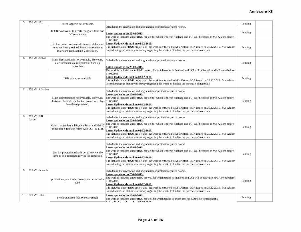
Event logger is not available. Pending
In CB two Nos. of trip coils energised from one
DC source only.Pending
For line protection, main-1, numerical distance
relay has been provided & electromechanical
relays are used as main-2 protection.
Pending
Main-II protection is not available. However,
electromechanical relay used as back up
protection.
Pending
LBB relays not available. Pending
7 220 kV A Station
Main-II protection is not available. However,
electromechanical type backup protection relays
have been provided.
Included in the renovation and upgradation of protection system works
Latest update as on 25-08-2015:
The work is included under R&U project for which tender is finalised and LOI will be issued to M/s Alstom before
31.08.2015.
Latest Update vide mail on 03-02-2016:
It is included under R&U project and the work is entrusted to M/s Alstom. LOA issued on 26.12.2015. M/s Alstom
is conducting sub stationwise survey regarding the works to finalise the purchase of materials.
Pending
Main-1 protection is Distance Relay and Main-2
protection is Back up relays with OCR & EFR.
Included in the renovation and upgradation of protection system works
Latest update as on 25-08-2015:
The work is included under R&U project for which tender is finalised and LOI will be issued to M/s Alstom before
31.08.2015.
Latest Update vide mail on 03-02-2016:
It is included under R&U project and the work is entrusted to M/s Alstom. LOA issued on 26.12.2015. M/s Alstom
is conducting sub stationwise survey regarding the works to finalise the purchase of materials.
Pending
Bus Bar protection relay is out of service, the
same to be put back to service for protection.
Included in the renovation and upgradation of protection system works
Latest update as on 25-08-2015:
The work is included under R&U project for which tender is finalised and LOI will be issued to M/s Alstom before
31.08.2015.
Latest Update vide mail on 03-02-2016:
It is included under R&U project and the work is entrusted to M/s Alstom. LOA issued on 26.12.2015. M/s Alstom
is conducting sub stationwise survey regarding the works to finalise the purchase of materials.
Pending
9 220 kV Kadakola
protection system to be time synchronized with
GPS
Included in the renovation and upgradation of protection system works.
Latest update as on 25-08-2015:
The work is included under R&U project, for which tender is finalised and LOI will be issued to M/s Alstom before
31.08.2015.
Latest Update vide mail on 03-02-2016:
It is included under R&U project and the work is entrusted to M/s Alstom. LOA issued on 26.12.2015. M/s Alstom
is conducting sub stationwise survey regarding the works to finalise the purchase of materials.
Pending
Synchronisation facility not available Pending
6 220 kV HebbalIncluded in the renovation and upgradation of protection system works.
Latest update as on 25-08-2015:
The work is included under R&U project, for which tender is finalised and LOI will be issued to M/s Alstom before
31.08.2015.
Latest Update vide mail on 03-02-2016:
It is included under R&U project and the work is entrusted to M/s Alstom. LOA issued on 26.12.2015. M/s Alstom
is conducting sub stationwise survey regarding the works to finalise the purchase of materials.
8 220 kV HSR
Layout
5 220 kV HAL
Included in the renovation and upgradation of protection system works.
Latest update as on 25-08-2015:
The work is included under R&U project for which tender is finalised and LOI will be issued to M/s Alstom before
31.08.2015.
Latest Update vide mail on 03-02-2016:
It is included under R&U project and the work is entrusted to M/s Alstom. LOA issued on 26.12.2015. M/s Alstom
is conducting sub stationwise survey regarding the works to finalise the purchase of materials.
10 220 kV Kolar Latest update as on 25-08-2015:
The work is included under R&U project, for which tender is under process. LOI to be issued shortly.
Latest Update vide mail on 03-02-2016:
It is included under R&U project and the work is entrusted to M/s Alstom. LOA issued on 26.12.2015. M/s Alstom
is conducting sub stationwise survey regarding the works to finalise the purchase of materials.
Annexure-XII
Page 45 of 96

DR and EL not provided. It is suggested that
DR and EL to be provided with time
synchronisation
Pending
11 220 kV
Naganathapura
R/S
Main-1: Numerical Distance Protection and
Main-2 is Back up protection with OCR & EFR.
Included in the renovation and upgradation of protection system works.
Latest update as on 25-08-2015:
The work is included under R&U project,for which tender is finalised and LOI will be issued to M/s Alstom before
31.08.2015.
Latest Update vide mail on 03-02-2016:
It is included under R&U project and the work is entrusted to M/s Alstom. LOA issued on 26.12.2015. M/s Alstom
is conducting sub stationwise survey regarding the works to finalise the purchase of materials.
Pending
100MVA Transformer 1&2 220 KV LA
counters are not available.Complied
The 220 KV Belgaum lines 1 & 2, Hubli Lines 1
& 2, Ambewadi Line-1 and Haveri Line-2 LA
counters are not available.
Complied
Main 2 protection is not available for all the 220
KV lines.Pending
Separate Event Logger, Disturbance Recorder
and GPS is not available.Pending
Event logger and DRS not available for Peenya
& Vrushabavathi Lines.Pending
Main II Distance protection Relays for all 220
Kv feeders is not available & the Protection
Coupler for Peenya & Vrushabavathi Lines are
not available.
Pending
GPS, Disturbance recorder and event logger are
not available and same to be provided. Control
panel annunciation not in working condition
except transformers
Pending
Main-II Distance protections were not propvided
in all 220 kV feeders and PLCC/Protection
coupler was not provided except 220 kV Hebbal
feeder
Pending
13Included in renovation and upgradation of protection system works.
Latest update as on 25-08-2015:
The work is included under R&U project, for which tender is under process. LOI to be issued shortly.
Latest Update vide mail on 03-02-2016:
It is included under R&U project and the work is entrusted to M/s Alstom. LOA issued on 26.12.2015. M/s Alstom
is conducting sub stationwise survey regarding the works to finalise the purchase of materials.
14 220 kV Peenya,
Bangalore Is being covered under R&M works under Peenya.
Latest update as on 25-08-2015:
Complete R&M of 220kV Peenya Sub station is taken up by KPTCL.The work is awarded to M/s Micron
Electricals,Bangalore and the work is under execution. Attending protection audit observations pertaining to Peenya
SS is taken up under R&M works.
Latest Update vide mail on 03-02-2016:
Attending protection audit observations at SRS Peenya is inculded under R&M works
10 220 kV Kolar Latest update as on 25-08-2015:
The work is included under R&U project, for which tender is under process. LOI to be issued shortly.
Latest Update vide mail on 03-02-2016:
It is included under R&U project and the work is entrusted to M/s Alstom. LOA issued on 26.12.2015. M/s Alstom
is conducting sub stationwise survey regarding the works to finalise the purchase of materials.
12 220 kV Narendra
SS
Latest update as on 25-08-2015 and vide mail on 03-02-2016:
LAs are provided and in working condition.
Included in the renovation and upgradation of protection system works.
Latest update as on 25-08-2015:
The work is included under R&U project, for which tender is under process. LOI to be issued shortly.
Latest Update vide mail on 03-02-2016:
It is included under R&U project and the work is entrusted to M/s Alstom. LOA issued on 26.12.2015. M/s Alstom
is conducting sub stationwise survey regarding the works to finalise the purchase of materials.
220 kV NRS
Rajajinagar
Annexure-XII
Page 46 of 96
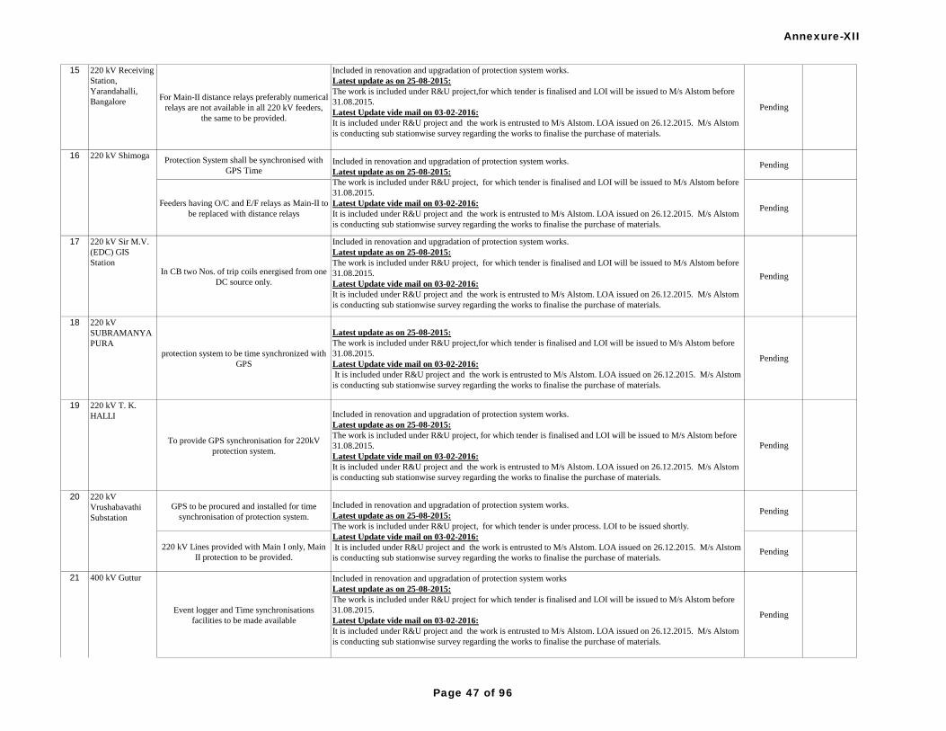
15 220 kV Receiving
Station,
Yarandahalli,
BangaloreFor Main-II distance relays preferably numerical
relays are not available in all 220 kV feeders,
the same to be provided.
Included in renovation and upgradation of protection system works.
Latest update as on 25-08-2015:
The work is included under R&U project,for which tender is finalised and LOI will be issued to M/s Alstom before
31.08.2015.
Latest Update vide mail on 03-02-2016:
It is included under R&U project and the work is entrusted to M/s Alstom. LOA issued on 26.12.2015. M/s Alstom
is conducting sub stationwise survey regarding the works to finalise the purchase of materials.
Pending
Protection System shall be synchronised with
GPS TimePending
Feeders having O/C and E/F relays as Main-II to
be replaced with distance relays Pending
17 220 kV Sir M.V.
(EDC) GIS
Station In CB two Nos. of trip coils energised from one
DC source only.
Included in renovation and upgradation of protection system works.
Latest update as on 25-08-2015:
The work is included under R&U project, for which tender is finalised and LOI will be issued to M/s Alstom before
31.08.2015.
Latest Update vide mail on 03-02-2016:
It is included under R&U project and the work is entrusted to M/s Alstom. LOA issued on 26.12.2015. M/s Alstom
is conducting sub stationwise survey regarding the works to finalise the purchase of materials.
Pending
18 220 kV
SUBRAMANYA
PURA
protection system to be time synchronized with
GPS
Latest update as on 25-08-2015:
The work is included under R&U project,for which tender is finalised and LOI will be issued to M/s Alstom before
31.08.2015.
Latest Update vide mail on 03-02-2016:
It is included under R&U project and the work is entrusted to M/s Alstom. LOA issued on 26.12.2015. M/s Alstom
is conducting sub stationwise survey regarding the works to finalise the purchase of materials.
Pending
19 220 kV T. K.
HALLI
To provide GPS synchronisation for 220kV
protection system.
Included in renovation and upgradation of protection system works.
Latest update as on 25-08-2015:
The work is included under R&U project, for which tender is finalised and LOI will be issued to M/s Alstom before
31.08.2015.
Latest Update vide mail on 03-02-2016:
It is included under R&U project and the work is entrusted to M/s Alstom. LOA issued on 26.12.2015. M/s Alstom
is conducting sub stationwise survey regarding the works to finalise the purchase of materials.
Pending
GPS to be procured and installed for time
synchronisation of protection system.Pending
220 kV Lines provided with Main I only, Main
II protection to be provided.Pending
Event logger and Time synchronisations
facilities to be made available
Included in renovation and upgradation of protection system works
Latest update as on 25-08-2015:
The work is included under R&U project for which tender is finalised and LOI will be issued to M/s Alstom before
31.08.2015.
Latest Update vide mail on 03-02-2016:
It is included under R&U project and the work is entrusted to M/s Alstom. LOA issued on 26.12.2015. M/s Alstom
is conducting sub stationwise survey regarding the works to finalise the purchase of materials.
Pending
400 kV Guttur
16 220 kV ShimogaIncluded in renovation and upgradation of protection system works.
Latest update as on 25-08-2015:
The work is included under R&U project, for which tender is finalised and LOI will be issued to M/s Alstom before
31.08.2015.
Latest Update vide mail on 03-02-2016:
It is included under R&U project and the work is entrusted to M/s Alstom. LOA issued on 26.12.2015. M/s Alstom
is conducting sub stationwise survey regarding the works to finalise the purchase of materials.
20 220 kV
Vrushabavathi
Substation
Included in renovation and upgradation of protection system works.
Latest update as on 25-08-2015:
The work is included under R&U project, for which tender is under process. LOI to be issued shortly.
Latest Update vide mail on 03-02-2016:
It is included under R&U project and the work is entrusted to M/s Alstom. LOA issued on 26.12.2015. M/s Alstom
is conducting sub stationwise survey regarding the works to finalise the purchase of materials.
21
Annexure-XII
Page 47 of 96

ICT-1 differential, bus bar relays and some of
220 kV lines distance relays are static type
relays and are not having the disturbance
recorder facilities. Replacement of the same
with numerical type relays
Included in renovation and upgradation of protection system works
Latest update as on 25-08-2015:
The work is included under R&U project for which tender is finalised and LOI will be issued to M/s Alstom before
31.08.2015.
Latest Update vide mail on 03-02-2016:
It is included under R&U project and the work is entrusted to M/s Alstom. LOA issued on 26.12.2015. M/s Alstom
is conducting sub stationwise survey regarding the works to finalise the purchase of materials.
Pending
400 kV Hoody
Substation
Main-II protection not provided in 220 kV
feeders instead Backup protection are provided.
Included in renovation and upgradation of protection system works
Latest update as on 25-08-2015:
The work is included under R&U projectfor which tender is finalised and LOI will be issued to M/s Alstom before
31.08.2015.
Latest Update vide mail on 03-02-2016:
It is included under R&U project and the work is entrusted to M/s Alstom. LOA issued on 26.12.2015. M/s Alstom
is conducting sub stationwise survey regarding the works to finalise the purchase of materials.
Pending
220 kV Hoody
Substation
Main-II relays not available in all 220 kV
feeders. The same to be provided.
220kV control and relay panels with main-1 and main-2 distance protection are being provided under R&M works.
Latest update as on 25-08-2015:
220kV control and relay panels with main-1 and main-2 distance protection are being provided under ongoing R&M
works.
Latest Update vide mail on 03-02-2016:
220kV control and relay panels with main-1 and main-2 distance protection are being provided under R&M works.
Pending
23
400 kV
Nelamangala &
220 kV
Nelamangala
Main II distance protection were not provided in
all 220 kV lines & PLCC/Protection Coupler
were not provided except Nittur & Dabuspet
lines
PLCC Protection Coupler provided for Nittur and Dabuspet lines.
The Main-II distance protection works for 220kV lines were included in Renovation and upgradation of protection
system project.
Latest update as on 25-08-2015:
The work is included under R&U project, for which tender is finalised and LOI will be issued to M/s Alstom before
31.08.2015.
Latest Update vide mail on 03-02-2016:
It is included under R&U project and the work is entrusted to M/s Alstom. LOA issued on 26.12.2015. M/s Alstom
is conducting sub stationwise survey regarding the works to finalise the purchase of materials.
Pending
Attended Complied
Separate Event Loggers are not available, GPS
are not synchronised with SAS & Distance
Protection Relays.
Event Logger of numerical protection relays are used for analysis. SAS & distance relays are synchronized with GPS. Complied
Main II relays not in service in 400 kV Hassan
line, 400 kV Talaguppa line & 400 kV Hoody
line-1 and the same may be made available in
the above feeders.
Main-2 relays provided to 400 V Hassan, Hoody-1 and Talguppa lines. Complied
It is noticed that the LA is failed in the same
phase (Talaguppa line) for 3 times previously.
Analysis may be done and take remedial action
to avoid reoccurrence.
Failure of LAs at Nelamangala was analysed and it was observed that comparitively more failure in the particular
batch of LAs supplied. LA failure occurred in other bays such as Hassan line., ICT etc also. Hence any site specific
cause could not be arrived with respect this particular observation.
Complied
400 kV Guttur
22
Phase-II
21
Annexure-XII
Page 48 of 96

Sl.
No. Name of
SubstationDetails of Protection Audit observation Action taken for attending the observation Remarks
One DC source is being user for protection.
Included in renovation and upgradation of protection system works
Latest update as on 14-09-2015:
LOI to be issued to the successful bidder.
Latest Update vide mail on 03-02-2016:
It is included under R&U project and the work is entrusted to M/s Alstom. LOA issued on 26.12.2015. M/s Alstom
is conducting sub stationwise survey regarding the works to finalise the purchase of materials.
Pending
DG set is not available.
Included in renovation and upgradation of protection system works
Latest update as on 14-09-2015:
LOI to be issued to the successful bidder.
Latest Update vide mail on 03-02-2016:
It is included under R&U project and the work is entrusted to M/s Alstom. LOA issued on 26.12.2015. M/s Alstom
is conducting sub stationwise survey regarding the works to finalise the purchase of materials.
Pending
2 220 kV A
Station
One DC source is being user for protection.
Included in renovation and upgradation of protection system works.
Latest update as on 25-08-2015:
The work is included under R&U project for which tender is finalised and LOI will be issued to M/s Alstom before
31.08.2015.
Latest Update vide mail on 03-02-2016:
It is included under R&U project and the work is entrusted to M/s Alstom. LOA issued on 26.12.2015. M/s Alstom
is conducting sub stationwise survey regarding the works to finalise the purchase of materials.
Pending
3 220 kV HSR Lay
Out S/S
CVT not provided in all phases of all feeders in
220 kV feeders.
Included in renovation and upgradation of protection system works
Latest update as on 25-08-2015:
The work is included under R&U project for which tender is finalised and LOI will be issued to M/s Alstom before
31.08.2015.
Latest Update vide mail on 03-02-2016:
It is included under R&U project and the work is entrusted to M/s Alstom. LOA issued on 26.12.2015. M/s Alstom
is conducting sub stationwise survey regarding the works to finalise the purchase of materials.
Pending
4 220 kV Kadakola
Recommended to put 220 kV busbar protection
system in service at the earliest possible.
Bus bar protetction scheme is being replaced by numerical bus bar protection scheme.
Latest update as on 25-08-2015:
The work is included under R&U project for which tender is finalised and LOI will be issued to M/s Alstom before
31.08.2015.
Latest Update vide mail on 03-02-2016:
It is included under R&U project and the work is entrusted to M/s Alstom. LOA issued on 26.12.2015. M/s Alstom
is conducting sub stationwise survey regarding the works to finalise the purchase of materials.
Pending
Numerical bus bar protection is being provided under renovation and upgradation of protection system works. Due to
space constraints for providing double bus system, providing bus sectionalizer is envisaged.
The issued was discussed in the special meeting of PCSC held on 19.08.2014, and the forum agrred to send the
modified proposal to Hon'ble CERC.
Latest update as on 25-08-2015:
Numerical bus bar protection is being provided under renovation and upgradation of protection system works. Due to
space constraints for providing double bus system, providing bus sectionalizer is envisaged.The work will be taken
up under proposed R&M works at Kolar.
Latest Update vide mail on 03-02-2016:
Numerical bus bar protection is being provided under renovation and upgradation of protection system works. Due to
space constraints for providing double bus system, providing bus sectionalizer is envisaged.
Dropped220 kV Single Bus System is available and bus
bar protection not provided. It is proposed for
provision of 220 kV double bus system with bus
bar protection.
220 kV Kolar5
220 kV Hebbal1
Annexure-XII
Page 49 of 96
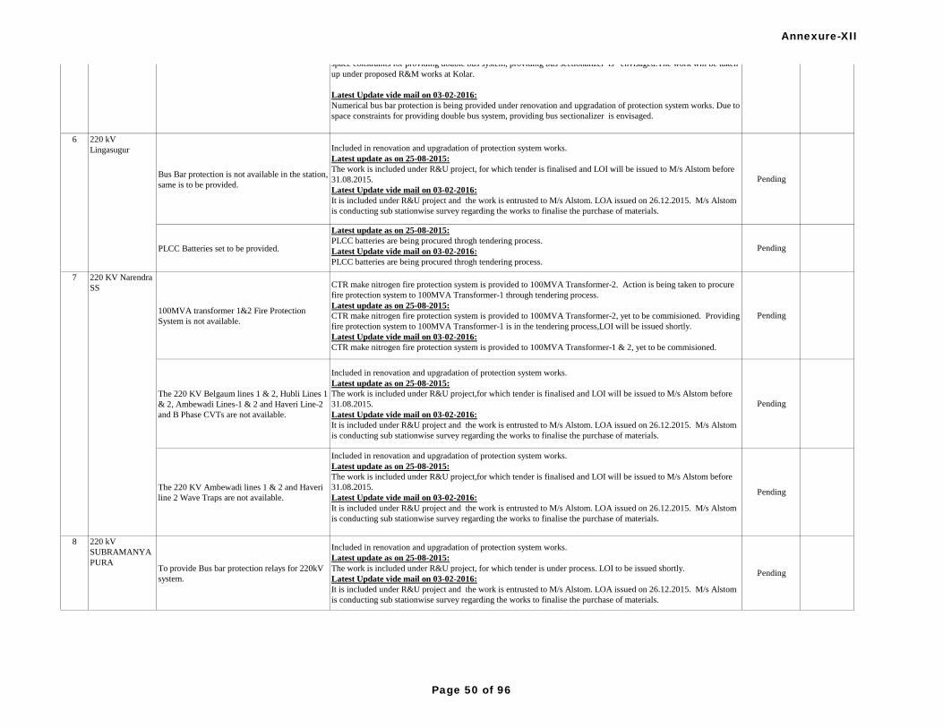
Bus Bar protection is not available in the station,
same is to be provided.
Included in renovation and upgradation of protection system works.
Latest update as on 25-08-2015:
The work is included under R&U project, for which tender is finalised and LOI will be issued to M/s Alstom before
31.08.2015.
Latest Update vide mail on 03-02-2016:
It is included under R&U project and the work is entrusted to M/s Alstom. LOA issued on 26.12.2015. M/s Alstom
is conducting sub stationwise survey regarding the works to finalise the purchase of materials.
Pending
PLCC Batteries set to be provided.
Latest update as on 25-08-2015:
PLCC batteries are being procured throgh tendering process.
Latest Update vide mail on 03-02-2016:
PLCC batteries are being procured throgh tendering process.
Pending
100MVA transformer 1&2 Fire Protection
System is not available.
CTR make nitrogen fire protection system is provided to 100MVA Transformer-2. Action is being taken to procure
fire protection system to 100MVA Transformer-1 through tendering process.
Latest update as on 25-08-2015:
CTR make nitrogen fire protection system is provided to 100MVA Transformer-2, yet to be commisioned. Providing
fire protection system to 100MVA Transformer-1 is in the tendering process,LOI will be issued shortly.
Latest Update vide mail on 03-02-2016:
CTR make nitrogen fire protection system is provided to 100MVA Transformer-1 & 2, yet to be commisioned.
Pending
The 220 KV Belgaum lines 1 & 2, Hubli Lines 1
& 2, Ambewadi Lines-1 & 2 and Haveri Line-2
and B Phase CVTs are not available.
Included in renovation and upgradation of protection system works.
Latest update as on 25-08-2015:
The work is included under R&U project,for which tender is finalised and LOI will be issued to M/s Alstom before
31.08.2015.
Latest Update vide mail on 03-02-2016:
It is included under R&U project and the work is entrusted to M/s Alstom. LOA issued on 26.12.2015. M/s Alstom
is conducting sub stationwise survey regarding the works to finalise the purchase of materials.
Pending
The 220 KV Ambewadi lines 1 & 2 and Haveri
line 2 Wave Traps are not available.
Included in renovation and upgradation of protection system works.
Latest update as on 25-08-2015:
The work is included under R&U project,for which tender is finalised and LOI will be issued to M/s Alstom before
31.08.2015.
Latest Update vide mail on 03-02-2016:
It is included under R&U project and the work is entrusted to M/s Alstom. LOA issued on 26.12.2015. M/s Alstom
is conducting sub stationwise survey regarding the works to finalise the purchase of materials.
Pending
8 220 kV
SUBRAMANYA
PURATo provide Bus bar protection relays for 220kV
system.
Included in renovation and upgradation of protection system works.
Latest update as on 25-08-2015:
The work is included under R&U project, for which tender is under process. LOI to be issued shortly.
Latest Update vide mail on 03-02-2016:
It is included under R&U project and the work is entrusted to M/s Alstom. LOA issued on 26.12.2015. M/s Alstom
is conducting sub stationwise survey regarding the works to finalise the purchase of materials.
Pending
220 kV
Lingasugur
220 KV Narendra
SS
Numerical bus bar protection is being provided under renovation and upgradation of protection system works. Due to
space constraints for providing double bus system, providing bus sectionalizer is envisaged.
The issued was discussed in the special meeting of PCSC held on 19.08.2014, and the forum agrred to send the
modified proposal to Hon'ble CERC.
Latest update as on 25-08-2015:
Numerical bus bar protection is being provided under renovation and upgradation of protection system works. Due to
space constraints for providing double bus system, providing bus sectionalizer is envisaged.The work will be taken
up under proposed R&M works at Kolar.
Latest Update vide mail on 03-02-2016:
Numerical bus bar protection is being provided under renovation and upgradation of protection system works. Due to
space constraints for providing double bus system, providing bus sectionalizer is envisaged.
Dropped220 kV Single Bus System is available and bus
bar protection not provided. It is proposed for
provision of 220 kV double bus system with bus
bar protection.
220 kV Kolar5
6
7
Annexure-XII
Page 50 of 96

9 220 kV T. K.
HALLI - KPTCL
To provide Bus bar protection for 220kV Bus
system at the earliest.
Included in renovation and upgradation of protection system works.
Latest update as on 25-08-2015:
The work is included under R&U project,for which tender is finalised and LOI will be issued to M/s Alstom before
31.08.2015.
Latest Update vide mail on 03-02-2016:
It is included under R&U project and the work is entrusted to M/s Alstom. LOA issued on 26.12.2015. M/s Alstom
is conducting sub stationwise survey regarding the works to finalise the purchase of materials.
Pending
10 220 kV
Yarandahalli,
BangaloreBusbar protection is not provided in the 220 kV
system, the same to be provided.
Included in renovation and upgradation of protection system works.
Latest update as on 25-08-2015:
The work is included under R&U project,for which tender is finalised and LOI will be issued to M/s Alstom before
31.08.2015.
Latest Update vide mail on 03-02-2016:
It is included under R&U project and the work is entrusted to M/s Alstom. LOA issued on 26.12.2015. M/s Alstom
is conducting sub stationwise survey regarding the works to finalise the purchase of materials.
Pending
11 400 kV Guttur
R/S - KPTCLAtmospheric conditions as specified by the
manufaturers of relays to be maintained for
smooth operation of relays like cooling system
which is observed insufficient.
Action is being taken for resotring/enhancing the existing cooling system.
Latest update as on 25-08-2015:
Action is being taken for resotring/enhancing the existing cooling system.Tender under process at CEE,TZ Tumkur.
Latest Update vide mail on 03-02-2016:
Action is being taken for resotring/enhancing the existing cooling system.
Pending
Annexure-XII
Page 51 of 96

Sl.
No.Name of
SubstationDetails of Protection Audit observation Action taken to attend the observation Remarks
Condition monitoring of switch yard equipments
need to be carried out at regular basis.Followed Complied
Synchonising is being used selectively.
Recommended for usage at all Lines.
Complete R&M of 220kV Somanahally SS is taken up by KPTCL, wherein conventional C&R panels are being
replaced by numerical relays and BCU mounted in bay kiosk .Synchroninzing facility is available in each BCU . Complied
Facility for downloading of disturbance records
is to be made available.
Set up for automatic downloading of DR &EL records is being provided under R&U project, for which tender is
finalised and the work is awarded to M/s Alstom.
KPTCL mail received on 14-09-2015:
LOI to be issued to the successful bidder.
Latest Update vide mail on 03-02-2016:
It is included under R&U project and the work is entrusted to M/s Alstom. LOA issued on 26.12.2015. M/s Alstom
is conducting sub stationwise survey regarding the works to finalise the purchase of materials.
Pending
Existing static type 220kV Bus Bar protection
scheme may be replaced by numerical type
scheme to have the bus bar protection in full
shape with all features.
The work is included under R&U project for which tender is finalised and the work is awarded to M/s Alstom.
KPTCL mail received on 14-09-2015:
LOI to be issued to the successful bidder.
Latest Update vide mail on 03-02-2016:
It is included under R&U project and the work is entrusted to M/s Alstom. LOA issued on 26.12.2015. M/s Alstom
is conducting sub stationwise survey regarding the works to finalise the purchase of materials.
Pending
Local SCADA should be kept in service on top
priority for smooth monitoring of the sub station
parameters and events.
Service support is not available for existing SCADA system of ABB. Replacement of main protection relays of lines
and ICTs by IEC 61850 protocol relays is considered under R&U project.Possibility of upgradation of the existing
SCADA by 61850 based SAS is explored by KPTCL.
KPTCL mail received on 14-09-2015:
Possibility of upgradation of the existing SCADA by 61850 based SAS is explored by KPTCL.
Latest Update vide mail on 03-02-2016:
Service support is not available for existing SCADA system of ABB. Replacement of main protection relays of lines
and ICTs by IEC 61850 protocol relays is considered under R&U project.
Pending
220kV feeders having O/C and E/F relays as
Main-II, to be replaced with distance relays
The work is included under R&U project for which tender is finalised and the work is awarded to M/s Alstom.
KPTCL mail received on 14-09-2015:
LOI to be issued to the successful bidder.
Latest Update vide mail on 03-02-2016:
It is included under R&U project and the work is entrusted to M/s Alstom. LOA issued on 26.12.2015. M/s Alstom
is conducting sub stationwise survey regarding the works to finalise the purchase of materials.
Pending
Auto reclosure function should be kept in
service in full shapeAttended Complied
A PT/CVT selector switches may be provided to
both main-1 &2 protections and Main-1 & II
may be kept on PT and CVT respectively or
either way.
Line / Bus CVT selection is available and functional as per the scheme provided. Complied
Combined (Phase-I & Phase-II)
1 220 kV
Somanahalli S/S
400 kV Talaguppa
S/S & 220 kV
Talaguppa S/S
2
Annexure-XII
Page 52 of 96

CTD trippingavailable on ICT-3. The same may
be provided on ICT-1 &2 also.Attended Complied
Earthmat resistance should be measured and
recorded periodically.Attended Complied
400 kV Talaguppa
S/S & 220 kV
Talaguppa S/S
2
Annexure-XII
Page 53 of 96

S. No. Name of
SubstationDetails of work Status of Implementation of Protection Audit Recommendations Remarks
Carrier scheme to be provided for 230kV
Mylapore feeder
Fibre laying is under progress. Time extension requested upto 30.06.2016.
Latest Update vide mail on 03-02-2016:
Fibre laying is under progress. Time extension requested upto 30.06.2016.
Pending
No protection during VT Fail condition. Same to
be reviewedComplied - Inbuilt protection is available during VT fuse fail - 11.01.2014. Complied
No Earth fault protection on HV & LV side of
transformer. Same to be provided
E/F settings for AUTOs not being adopted in TANTRANSCO.
Latest Update vide mail on 03-02-2016:
E/F settings for AUTOs not being adopted in TANTRANSCO.
Pending
O/L settings oauto transformers to be reviewed complied.Uniform setting procedure adopted Complied
Separate earthing for DC system (110 V DC) to
be providedProvided on 01.05.2014. Complied
Only Bus PT supply is available for Main I & II
protection, no line VT supply is available for
protection. Same needs review
PT allotted and will be completed by 31.03.2015.
Latest Update as on 27-08-2015:
PT allotted and to be erected and will be completed by 31.12.2015.
Latest Update vide mail on 03-02-2016:
PT allotted and to be erected and will be completed by 30.06.2016.
Pending
No Capacitor Tripping Devices are kept in
service for Feeders and Transformers. Same
needs review
Capacitor trip device is not in service,since nuisance trippings were observed.
Latest Update vide mail on 03-02-2016:
Capacitor trip device is not in service, since nuisance trippings were observed.
Pending
Relay settings for feeders and transformers need
reviewBeing reviewed whenever needed. Complied
Time synchronising with GPS to be provided
for 230kV protection system
Time sync with GPS provided and is in service.Feasibility study is under progress for GPS, DR and EL.
Latest Update as on 27-08-2015:
Procurement action initiated. Specification approval under progress. Time extension requested up to 30.06.2016.
Latest Update vide mail on 03-02-2016:
Procurement action initiated. Time extension requested up to 30.06.2016.
Pending
Auto reclosure to be enabled for feeders. complied on 11.01.2014. Complied
Power swing block settings to be reviewed. complied.Adopted as recommended by SRPC. Complied
Earth fault relay to be provided on HV & LV
sides of Auto t/p # 1, 2 and TO # 3 t/f. Over
fluxing relayto be provided.
E/F settings for AUTOs not being adopted in Tantransco.
Latest Update vide mail on 03-02-2016:
E/F settings for AUTOs not being adopted in TANTRANSCO.
Pending
OT1 and WT1 indicators suspected for not
working. Same needs to be rectified. Defects rectified on 10.12.2012 and indication available at present. Complied
PRV device to be made available on Auto T/f #
1 and 2.PRV available in Auto 1. Explosion vent available in Auto 2. Complied
2 230 kV Ennore
(ETPS)
TANGEDCO
Phase-I
1 230 kV Basin
Bridge Substation
Annexure-XII
Page 54 of 96
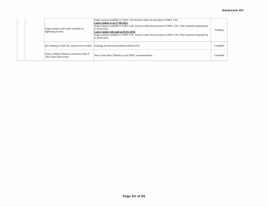
Surge counters to be made available on
lightening arrestor.
Surge counters available in 110kV LAS.Action is taken for provision in 230kV LAS.
Latest Update as on 27-08-2015:
Surge counters available in 110kV LAS. Action is taken for provision in 230kV LAS. Time extension requested up
to 30.06.2016.
Latest Update vide mail on 03-02-2016:
Surge counters available in 110kV LAS. Action is taken for provision in 230kV LAS. Time extension requested up
to 30.06.2016.
Pending
DC earthing in 220V DC system to be rectified Earthing checked and rectified on 08.05.2014 Complied
Zone-2 timing of distance protection relay of
23kV kines need reviewZone 2 time delay 350mSec as per SRPC recommendation. Complied
2 230 kV Ennore
(ETPS)
Annexure-XII
Page 55 of 96

Different type and Make of distance protection
relays to be provided for Main-I & Main-II
protection for 230kV feeders
Realys supplied and are to be commissioned. Time extension requested upto 31.03.2015.
Latest Update as on 27-08-2015:
Relays are being procured in phased manner. Second phase procurement under progress and will be commissioned
by 30.06.2016.
Latest Update vide mail on 03-02-2016:
Relays are being procured in phased manner. Second phase procurement under progress and will be commissioned
by 30.06.2016.
Pending
Remote temperature indicators to be provided
for station transformers.
Will be completed during annual shut down 2014.
Latest Update as on 27-08-2015:
Action taken for procurement. Time extension requested up to 30.06.2016.
Latest Update vide mail on 03-02-2016:
Action taken for procurement. Time extension requested up to 30.06.2016.
Pending
4 230 kV PUSHEP
Switchyard
(Pykara Ultimate
S/S (GEN.) DC leakage in the station to be rectified complied on July 2013 Complied
Main-I and Main-II protection schemes to be fed
from separate DC source. Provision for the same
to be done.
completed during August 2014.
Complied
PLCC protection coupler to be made available
for MTPS-Stage-III and MTPH feeders.
Tender opened.Procurement action in progress. Time extension requested upto 31.03.2015.
Latest Update as on 27-08-2015:
Material supplied. Will be erected and commissioned with in two months.
Latest Update vide mail on 03-02-2016:
PLCC protection coupler provided in MTPS Stage-III. In MTPH feeder, protection coupler will be provided.
Pending
Synchronisation cores of Line VT and Bus VT
are of different voltage ratios and same needs
review
Reviewed. No practical difficulties experienced. Complied
3 230 kV North
Chennai TPS
5 230kV Mettur
Thermal Power
Station
CTD protection to be provided in all 230KV
feeders and Transformers.
It is noted that in case of DC supply failure, the capacitor trip device would trip the circuit breaker. TANTRANSCO
requested the item be dropped as the reliability of DC supply is ensured by two DC sources for the trip coils. The
issue was discussed and the PCSC forum concluded that if provision for two DC sources were there for trip coils in
the Substation, then capacitor trip device could be dispensed with.
The issue was discussed in the special meeting of PCSC held on 19.08.2014, and the forum agreed to drop the
Item.
Dropped
Annexure-XII
Page 56 of 96

Time synchronising with GPS to be provided
for protection relays.
Feasibility study is under progress for GPS, DR and EL.
Latest Update as on 27-08-2015:
Procurement action initiated. Specification approval under progress. Time extension requested up to 30.06.2016.
Latest Update vide mail on 03-02-2016:
Procurement action initiated. Time extension requested up to 30.06.2016.
Pending
Both Main-1& Main-2 distance protection relays
of 230 kV feeders to are be of numerical type.
Static distance relays to be replaced with
numerical relays.
Relays supplied and are to be commissioned. Time extension requested upto 31.03.2015.
Latest Update as on 27-08-2015:
Relays are being procured in phased manner. Second phase procurement under progress and will be commissioned
by 30.06.2016.
Latest Update vide mail on 03-02-2016:
Relays are being procured in phased manner. Second phase procurement under progress and will be commissioned
by 30.06.2016.
Pending
5 230kV Mettur
Thermal Power
Station
Annexure-XII
Page 57 of 96

S. No. Name of
SubstationDetails of work Status of Implementation of Protection Audit Recommendations Remarks
For 230 kV Mylapore Feeder Protection
DC System
For 48V (PLCC) only 1 set of Battery, No back
up is available.
PO placed. Will be commissioned by 31.3.15.
Latest Update as on 27-08-2015:
Procurement action under progress. Time extension requested up to 30.06.2016.
Latest Update vide mail on 03-02-2016:
Procurement action under progress. Time extension requested up to 30.06.2016.
Pending
General
DG set is required for alternate source.
Procurement to be made. Will be provided by 30.06.2015.
Latest Update as on 27-08-2015:
Administrative approval obtained. Procurement action under progress. Time extension requested up to 30.06.2016.
Latest Update vide mail on 03-02-2016:
Administrative approval obtained. Procurement action under progress. Time extension requested up to 30.06.2016.
Pending
Synchronisation relay not available for feeders.
Being done manually by watching indicating
meters
Procurement to be made.Will be completed by 30.09.2015.
Latest Update vide mail on 03-02-2016:
The issue was discussed in the special meeting of PCSC held on 19.08.2014, and the forum agreed to drop the Item.
Pending
Since switchyard is very old, it is advisable to
physically see the rusting status of earth mat.
Switchyard equipment earthing needs to be
improved.
Earth mat is being watched and improved regularly Complied
No LA is available on R-phase LV side of Auto
# 2LAS provided on 05.12.2012 Complied
Dedicated feeder PT/CVT not available for
feeders protection. However, single phase CVT
available for measurement and synchronisation
purpose.
Procurement to be made. Will be completed by 30.06.2016 .
Latest Update as on 27-08-2015:
Administrative approval obtained. Procurement action under progress. Time extension requested up to 30.06.2016.
Latest Update vide mail on 03-02-2016:
Administrative approval obtained. Procurement action under progress. Time extension requested up to 30.06.2016.
Pending
3 230 kV Kundah
PH - II S/S
230 kV GC Breaker to be erected and
commissioned urgently to avoid tripping of tie
feeders in the event of tripping of auto
transformers
CT to be allotted .Work will be taken up on availing LC.Time extension requested upto 30.06.2015.
Latest Update as on 27-08-2015:
Breaker & CT erected. Control cables to be layed. Defective isolator to be replaced. Time extension requested up to
30.06.2016.
Latest Update vide mail on 03-02-2016:
Breaker & CT erected. Control cables to be layed. Defective isolator to be replaced. Time extension requested up to
30.06.2016.
Pending
4 230 kV Kundah
PH - III S/S -
TANTRANSCO2 sets of LA's have been provided at bus only.
Second core of Bus VT has been used for line
protection. Line CVTs are only for
synchronising purpose.
Procurement to be made. Will be completed by 30.06.2016
Latest Update as on 27-08-2015:
Administrative approval obtained. Procurement action under progress. Time extension requested up to 30.06.2016.
Latest Update vide mail on 03-02-2016:
Administrative approval obtained. Procurement action under progress. Time extension requested up to 30.06.2016.
Pending
TANGEDCO
Phase-II
1 230 kV Basin
Bridge SS
2 230 kV Ennore,
Chennai (ETPS) -
TANTRANSCO
Annexure-XII
Page 58 of 96
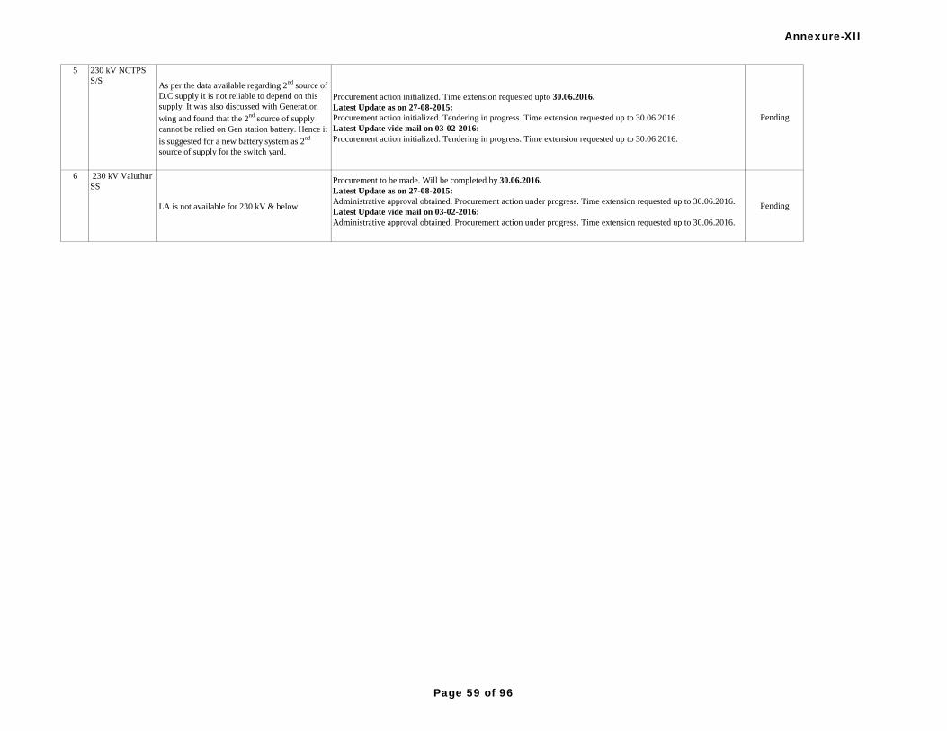
5 230 kV NCTPS
S/SAs per the data available regarding 2
nd source of
D.C supply it is not reliable to depend on this
supply. It was also discussed with Generation
wing and found that the 2nd
source of supply
cannot be relied on Gen station battery. Hence it
is suggested for a new battery system as 2nd
source of supply for the switch yard.
Procurement action initialized. Time extension requested upto 30.06.2016.
Latest Update as on 27-08-2015:
Procurement action initialized. Tendering in progress. Time extension requested up to 30.06.2016.
Latest Update vide mail on 03-02-2016:
Procurement action initialized. Tendering in progress. Time extension requested up to 30.06.2016.
Pending
6 230 kV Valuthur
SS
LA is not available for 230 kV & below
Procurement to be made. Will be completed by 30.06.2016.
Latest Update as on 27-08-2015:
Administrative approval obtained. Procurement action under progress. Time extension requested up to 30.06.2016.
Latest Update vide mail on 03-02-2016:
Administrative approval obtained. Procurement action under progress. Time extension requested up to 30.06.2016.
Pending
Annexure-XII
Page 59 of 96

S. No. Name of
SubstationDetails of work Status of Implementation of Protection Audit Recommendations Remarks
Static relays are to be replaced with numerical
relays
Relays supplied and are to be commissioned. Time extension requested upto 31.03.2015.
Latest Update as on 27-08-2015:
230kV feeder 5 numbers replaced, 110 kV feeder 10 numbers replaced.
Complied
V/F protection for transformers to be made
availableEnabled. Complied
REF protection to be implemented for
Transformers (Capacity below 100 MVA)
Neutral CT is to be provided. Procurement to be done.Time extension requested upto 30.06.2016.
Latest Update vide mail on 03-02-2016:
Neutral CT is to be provided. Procurement to be done.Time extension requested upto 30.06.2016.
Pending
DC leakages are to be complied for DC source I. complied on 16.03.2013 Complied
synchronizing facility to be made available.
TANTRASNCO informed that since synchronizing trolley is available for synchronizing purpose. The
synchronizing facility by synchronizing panel need not to be insisted . TANTRANSCO requested to drop the audit
point.
The issue was discussed in the special meeting of PCSC held on 19.08.2014, and the forum agreed to drop the
Item.
Dropped
REF protection to be made available. REF protection enabled on 25.11.2013 Complied
Time synchronising with GPS to be provided
for protection relays.
Feasibility study is under progress for GPS, DR and EL.
Latest Update as on 27-08-2015:
Procurement action initiated. Specification approval under progress. Time extension requested up to 30.06.2016.
Latest Update vide mail on 03-02-2016:
Procurement action initiated. Specification approval under progress. Time extension requested up to 30.06.2016.
Pending
Static distance relay to be replaced with
numerical relays. Pending
Diiferent type and Make of distance protection
relays to be provided for Main-I & Main-II
protection for 230kV Arasur feeder.
Pending
TANTRANSCO
Phase-I
1 230 kV Arni
Substation
3 230 kV Gobi
Substation
Realys supplied and are to be commissioned. Time extension requested upto 31.03.2015.
Latest Update as on 27-08-2015:
Phase-I Relay procurement completed & commissioned. Second phase procurement under progress. Time extension
requested up to 30.06.2016.
Latest Update vide mail on 03-02-2016:
1. 7 nos. Static Relays replaced with Numerical Relays and 3 more Static Relays are to be replaced.
2. Phase-I Relay procurement completed & commissioned. Second phase procurement under progress. Time
extension requested up to 30.06.2016.
Annexure-XII
Page 60 of 96

Time synchronising with GPS to be provided
for protection relays.
Feasibility study is under progress for GPS, DR and EL.
Latest Update as on 27-08-2015:
Procurement action initiated. Specification approval under progress. Time extension requested up to 30.06.2016.
Latest Update vide mail on 03-02-2016:
Procurement action initiated. Specification approval under progress. Time extension requested up to 30.06.2016.
Pending
Static distance relay to be replaced with
numerical relays. Complied on 08.02.2013. Complied
Diiferent type and Make of distance protection
relays to be provided for Main-I & Main-II
protection for 230kV Arasur and K.R.Thoppur
feeders.
Realys supplied and are to be commissioned. Time extension requested upto 31.03.2015.
Latest Update as on 27-08-2015:
Main-II relay MICOM.P.442 replaced by CG make ZLV relay on 11.6.2015 for 230 kv KR'Thoppur feeder
1.No Relay for Arasur Feeder to be replaced. This will be replaced before 31.10.2015.
Latest Update vide mail on 03-02-2016:
Main-II relay MICOM.P.442 replaced by CG make ZLV relay on 11.6.2015 for 230 kv KR'Thoppur feeder.
1.No Relay for Arasur Feeder to be replaced. This will be replaced before 30.06.2016.
Pending
In Busbar Protection same CT is used for Main
& Check zone relay. Same needs review
UE make Bus bar protection scheme available. The current circuits of Main and Check are in series and hence taken
from same core.CT circuit supervision and metrosil are common for main and check and hence separate CT cores
cannot be used. If BBP panel is replaced with numerical relay also, the low impedance scheme has built in check
zone . However the stability in operation of BBP is ensured in the scheme and hence replacing the existing 4 core CT
with 5 core CT is felt not necessary.
Complied
5 230 kV Kayathar
Substation Earth resistance to be measured and recorded. Earth resistance is measured and recorded on 21.3.14 (0.6Ω). Complied
During VT fail condition no protection is
available (Backup 1> disabled). Same needs
review
complied on 07.08.2014. Complied
No E/L relay protection on ATR 1, 2 & 3 HVs.
Same to be provided
E/F settings for AUTOs not being adopted in Tantransco.
Latest Update vide mail on 03-02-2016:
E/F settings for AUTOs not being adopted in Tantransco.
Pending
V/F protection is not available on ATR-1, 2 & 3.
Same to be provided.Enabled on 03.07.2014. Complied
Different type and Make of distance protection
relays to be provided for Main-I & Main-II
protection for 230kV feeders
Relays supplied and are to be commissioned. Time extension requested upto 31.03.2015.
Latest Update as on 27-08-2015:
Relays are being procured in phased manner. Second phase procurement under progress and will be completed by
30.06.2016.
Latest Update vide mail on 03-02-2016:
Different type relays available for Main I and Main II.
Complied
Only Bus PT supply is available for Main I & II
protection. There is no line VT supply available
for protection. Same to be reviewed and
rectified.
PT to be procured and will be completed by 30.06.2016.
Latest Update as on 27-08-2015:
Administrative approval obtained.Procurement action under progress. Time extension requested up to 30.06.2016.
Latest Update vide mail on 03-02-2016:
Administrative approval obtained.Procurement action under progress. Time extension requested up to 30.06.2016.
Pending
4 230 kV Ingur
Substation
6 230 kV Korattur
Substation
Annexure-XII
Page 61 of 96

No capacitor tripping devices are provided on
230 kV feeders & ATRs. Provision for the same
to be done
It is noted that in case of DC supply failure, the capacitor trip device would trip the circuit breaker. TANTRANSCO
requested the item be dropped as the reliability of DC supply is ensured by two DC sources for the trip coils. The
issue was discussed and the PCSC forum concluded that if provision for two DC sources were there for trip coils in
the Substation, then capacitor trip device could be dispensed with.
The issue was discussed in the special meeting of PCSC held on 19.08.2014, and the forum agreed to drop the
Item.
Dropped
Relay settings for feeders and transformers need
reviewReviewed whenever needed Complied
Time synchronising with GPS to be provided
for 230kV protection system
Feasibility study is under progress for GPS, DR and EL.
Latest Update as on 27-08-2015:
Procurement action initiated. Specification approval under progress. Time extension requested up to 30.06.2016.
Latest Update vide mail on 03-02-2016:
Procurement action initiated. Time extension requested up to 30.06.2016.
Pending
Time synchronising with GPS to be provided
for protection relays.
Feasibility study is under progress for GPS, DR and EL.
Latest Update as on 27-08-2015:
Procurement action initiated. Specification approval under progress. Differential & Busbar Relays will be replaced
before 30.06.2016.
Latest Update vide mail on 03-02-2016:
Procurement action initiated. Specification approval under progress. Time extension requested up to 30.06.2016.
Pending
Static distance protection relays to be replaced
with numerical relays.
Relays supplied and are to be commissioned. Time extension requested upto 31.03.2015.
Latest Update as on 27-08-2015:
Relays are being procured in phased manner. Second phase procurement under progress and will be commissioned
before 30.06.2016.
Latest Update vide mail on 03-02-2016:
In ALUNDUR 230kv ss all the 230kv feeder relays are replaced with numerical relays (Main I MICOM P442, Main
II CG ZIV)
Complied
Station Event loggerto be provided
Feasibility study is under progress for GPS, DR and EL.
Latest Update as on 27-08-2015:
Procurement action initiated. Specification approval under progress. Differential & Busbar Relays will be replaced
before 30.06.2016.
Latest Update vide mail on 03-02-2016:
Procurement action initiated. Specification approval under progress. Time extension requested up to 30.06.2016.
Pending
O/C and E/f relay setting on HV & LV sides of
both auto transformers need review.
Uniform setting adopted for O/C. E/F setting not adopted in TANTRANSCO.
Latest Update vide mail on 03-02-2016:
Uniform setting adopted for O/C. E/F setting not adopted in TANTRANSCO.
Pending
Diiferent type and Make of distance protection
relays for Main-I & Main-II protection to be
provided for 230kV feeders
Relays supplied and are to be commissioned. Time extension requested upto 31.03.2015.
Latest Update as on 27-08-2015:
Relays are being procured in phased manner. Second phase procurement under progress and will be commissioned
by 30.06.2016.
Latest Update vide mail on 03-02-2016:
Relays are being procured in phased manner. Second phase procurement under progress and will be commissioned
by 30.06.2016.
Pending
DC earthing in 220V DC system to be rectified DC earthing rectified on 08.11.2012. Complied
8 230 kV Manali
Substation
6 230 kV Korattur
Substation
7 230 kV Alundur
Substation
Annexure-XII
Page 62 of 96

Earth resistance meaured on 07.02.2009. It is
observed to be violating in more number of
earth pits. The same to be rectified
Combined earth resistance measured.Individual earth resistance will be measured on availing LC by
30.09.14..
Latest Update as on 27-08-2015 and vide mail on 03-02-2016:
Upgradation to 400/230kV GIS SS work has been taken up.
Pending
Carrier scheme to be provided for 230kV Basi
bridge feeder
Fibre laying is under progress.Time extension requested upto 30.06.2016.
Latest Update vide mail on 03-02-2016:
Fibre laying is under progress.Time extension requested upto 30.06.2016.
Pending
No protection during VT Fail condition. Same to
be reviewedComplied Complied
Static Main-2 relay of 230kV Basin bridge
feeder to be replaced with Numerical relaycomplied on 14.4.2013. Complied
No Earth fault protection on HV & LV side.
Same to be reviewed and provided
E/F settings for AUTOs not being adopted in Tantransco.
Latest Update vide mail on 03-02-2016:
E/F settings for AUTOs not being adopted in Tantransco.
Pending
Earth leakage monitoring system to be provided complied Complied
Separate earthing for 220 V & 48V DC system
to be providedProvided on 30.07.14 Complied
Only Bus PT supply is available for Main I & II
protection, no line VT supply is available for
protection. Same needs review
Procurement action in progress. Time extension requested upto 30.06.2016.
Latest Update as on 27-08-2015:
Administrative approval obtained.Procurement action under progress. Time extension requested up to 30.06.2016.
Latest Update vide mail on 03-02-2016:
Administrative approval obtained. Procurement action under progress. Time extension requested up to 30.06.2016.
Pending
Time synchronising with GPS to be provided
for 230kV protection systemPending
Provision for station event logger to be done Pending
8 230 kV Manali
Substation
9 230 kV Mylapore
Substation
Feasibility study is under progress for GPS, DR and EL.
Latest Update as on 27-08-2015:
Procurement action initiated. Specification approval under progress. Time extension requested up to 30.06.2016.
Latest Update vide mail on 03-02-2016:
Procurement action initiated. Specification approval under progress. Time extension requested up to 30.06.2016.
It is noted that in case of DC supply failure, the capacitor trip device would trip the circuit breaker. TANTRANSCO
requested the item be dropped as the reliability of DC supply is ensured by two DC sources for the trip coils. The
issue was discussed and the PCSC forum concluded that if provision for two DC sources were there for trip coils in
the Substation, then capacitor trip device could be dispensed with.
The issue was discussed in the special meeting of PCSC held on 19.08.2014, and the forum agreed to drop the
Item.
No Capacitor Tripping Devices are kept in
service for Feeders and Transformers. Same
needs review
Dropped
Annexure-XII
Page 63 of 96

Time synchronising with GPS to be provided
for protection relays.Pending
Station Event Logger, Disturbance Recorder
with dedicated computer systems, printers to be
provided.
Pending
Trip circuit supervision relay to be provided for
both trip coils for 230 kV Veerapuram, 230 kV
Kalpakkam, 230 kV Kalivanthapattu, 230 kV
Oragadam, 230/110 kV Auto 1 HV side
Time extension reuested upto 30.06.2017 since approval being sought for R&M.
Latest Update as on 27-08-2015:
R&M work for the substation is approved. Total renovation and comply with recommendation will be done. Time
extension requested up to 30.11.2016.
Latest Update vide mail on 03-02-2016:
R&M work for the substation is approved. Total renovation and comply with recommendation will be done. Time
extension requested up to 30.11.2016.
Pending
Provision for supervision of all the trip coils
through the TSR relay to be examined.
Time extension reuested upto 30.06.2017 since approval being sought for R&M.
Latest Update as on 27-08-2015:
R&M work for the substation is approved. Total renovation and comply with recommendation will be done. Time
extension requested up to 30.11.2016.
Latest Update vide mail on 03-02-2016:
R&M work for the substation is approved. Total renovation and comply with recommendation will be done. Time
extension requested up to 30.11.2016.
Pending
High water content in auto transformer oil test
report needs review and suitable actionsOil circulation completed 24.03.2014. Complied
It is found that relays of the same C&R panels
are placed in different locations of other C&R
panels in many bays. It is very difficult for the
SS operator to identify the relays during
emergency condition. Hence relays shall be
placed on the respective feeder panel to be
examined.
Time extension reuested upto 30.06.2017 since approval being sought for R&M.
Latest Update as on 27-08-2015:
R&M work for the substation is approved. Total renovation and comply with recommendation will be done. Time
extension requested up to 30.11.2016.
Latest Update vide mail on 03-02-2016:
R&M work for the substation is approved. Total renovation and comply with recommendation will be done. Time
extension requested up to 30.11.2016.
Pending
TMS of auto transformers for over currrent
relays (HV/LV) to be reviewed and correctedUniform setting adopted Complied
Replacement of all static relays (Differential,
Busbar, Distance etc) to be done with numerical
type relay
Relays supplied and are to be commissioned. Time extension requested upto 31.03.2015.
Latest Update as on 27-08-2015:
4 Nos. Numerical distance protection relays replaced in 230 kV feeders. Complied
Since the length of 230 kV Veerapuram line is
around 650 mts, sensitivity of performance of
distance protection for that shortest line needs to
be examined.
Numerical relay available and performance satisfactory Complied
10 230 kV Pugalur
SubstationFeasibility study is under progress for GPS, DR and EL.
Latest Update as on 27-08-2015:
Procurement action initiated. Specification approval under progress. Time extension requested up to 30.06.2016.
Latest Update vide mail on 03-02-2016:
Procurement action initiated. Specification approval under progress. Time extension requested up to 30.06.2016.
11 230 kV
Singaperumal
Koil Substation
Annexure-XII
Page 64 of 96

Carrier aided protection scheme to be provided
for 230 kV Oragadam feeder
PO issued for end equipments. Will be completed by 31.03.2015.
Latest Update as on 27-08-2015:
Equipment erection work under progress. Will be commissioned within two months.
Latest Update vide mail on 03-02-2016:
Equipment erection work under progress. Will be commissioned by 30.06.2016.
Pending
Provsion for Direct trip transmission signal on
operation of Bus bar/LBB relay for all the lines
to remote end to be provided.
Already adopted Complied
DC earthing in DC system to be rectified
leakage Pending
Labelling to be done for all the relays in panels
to be provided Pending
Cable Duct near Auto transformer 3 needs to br
repairedPending
Over flux protection to be provided for Auto
transformers .
Relays supplied and are to be commissioned. Time extension requested upto 31.03.2015.
Latest Update as on 27-08-2015:
Over flux protection enabled for Auto 4. Relays allotted for other 3 Auto transformers . Will be commissioned
within a month.
Latest Update vide mail on 03-02-2016:
Over flux protection enabled for Auto 4. Relays allotted for other 3 Auto transformers . Will be commissioned by
30.06.2016.
Pending
Battery earth leakage meters provided for DC
source I & II are not in working condition. Same
needs to be rectified.
Earth leakage meters rectified and in service. Complied
Non Directional Over Current relay with 150%
on both sides of all Auto Transformers are
provided. Earth fault relay on both side are not
adopted. Same needs review.
Uniform setting adopted for O/C. E/F settings for AUTOs not being adopted in Tantransco.
Latest Update vide mail on 03-02-2016:
Uniform setting adopted for O/C. E/F settings for AUTOs not being adopted in Tantransco.
Pending
Transmission line earth wire not connected to
SS earth mat at Tondiarpet. Same needs review
and rectification
Work will be takenup. Time extension requested upto 31.03.2015.
Latest Update as on 27-08-2015 and vide mail on 03-02-2016:
Work to be takenup. Time extension requested up to 30.11.2016.Pending
100 MVA, 230/110 kV transformer # 1 &2,
back up O/C relays setting need review. Earth
fault relays to be provided on both HV & LV
side of ICT's
Uniform setting adopted for O/C. E/F settings for AUTOs not being adopted in Tantransco
Latest Update vide mail on 03-02-2016:
Uniform setting adopted for O/C. E/F settings for AUTOs not being adopted in Tantransco.
Pending
11 230 kV
Singaperumal
Koil Substation
Time extension reqested upto 30.06.2017 since approval being sought for R&M.
Latest Update as on 27-08-2015:
R&M work for the substation is approved. Total renovation and comply with recommendation will be done. Time
extension requested up to 30.11.2016.
Latest Update vide mail on 03-02-2016:
R&M work for the substation is approved. Total renovation and comply with recommendation will be done. Time
extension requested up to 30.11.2016.
12 230 kV
Thiruvalam
Substation
13 230 kV
Tondiarpet
Substation
Annexure-XII
Page 65 of 96

REF for transformer # 1, overfluxing relays for
both t/f # 1, 2 to be provided
Neutral CT to be provided for REF protection. Tender opened for procurement of relay. Time extension requested
upto 30.06.2016.
Latest Update as on 27-08-2015 and vide mail on 03-02-2016:
Neutral CT is to be provided. Administrative approval obtained. Procurement action under progress. Time extension
requested up to 30.06.2016.
Pending
DC earthing in 220V DC system to be rectified complied on 3.8.2012. Complied
Separate treated earthpit for DG set to be
provided. Body of DG Set to be earthed with
suitable flat or conductor.
Separate earth pit provided on 21.05.2014. Complied
Zone separation for Bus Bar Protection needs to
be done. .
Time extension reuested upto 30.06.2017 since approval being sought for R&M.
Latest Update as on 27-08-2015:
R&M work for the substation is approved. Total renovation and comply with recommendation will be done. Time
extension requested up to 30.11.2016.
Latest Update vide mail on 03-02-2016:
R&M work for the substation is approved. Total renovation and comply with recommendation will be done. Time
extension requested up to 30.11.2016.
Pending
Staticrelays to be replaced with Numerical
Relays.Pending
V/F Protection to be enabled in autotransformers
upto the level of 230 kVPending
Time synchronising with GPS to be provided
for 400 & 230kV protection system
Feasibility study is under progress for GPS, DR and EL.
Latest Update as on 27-08-2015:
Procurement action initiated. Specification approval under progress. Time extension requested up to 30.06.2016.
Latest Update vide mail on 03-02-2016:
Procurement action initiated. Time extension requested up to 30.06.2016.
Pending
Different type and Make of distance protection
relays to be provided for Main-I & Main-II
protection for 230kV feeders
Relays supplied and are to be commissioned. Time extension requested upto 31.03.2015.
Latest Update as on 27-08-2015:
Relays are being procured in phased manner. Second phase procurement under progress and will be commissioned
by 30.06.2016.
Latest Update vide mail on 03-02-2016:
Relays are being procured in phased manner. Second phase procurement under progress and will be commissioned
by 30.06.2016.
Pending
Earth leakage Relays to be made functional Complied on 17.05.2014. Complied
Possibility of providing time synchronising
system (GPS Unit) for protection relays.
Feasibility study is under progress for GPS, DR and EL.
Latest Update as on 27-08-2015:
Procurement action initiated. Specification approval under progress. Time extension requested up to 30.06.2016.
Complied
14 230kV
Singarapettai
Substation
Relays supplied and are to be commissioned. Time extension requested upto 31.03.2015.
Latest Update as on 27-08-2015:
R&M work for the substation is approved. Total renovation and comply with recommendation will be done. Time
extension requested up to 30.11.2016.
Latest Update vide mail on 03-02-2016:
R&M work for the substation is approved. Total renovation and comply with recommendation will be done. Time
extension requested up to 30.11.2016.
15 400 kV Alamathy
Substation &
230kV Alamathy
Substation
16 400 kV
K.R.Thoppur
Substation
(Salem)
13 230 kV
Tondiarpet
Substation
Annexure-XII
Page 66 of 96

The existing Static Distance Protection Relays
to be replaced with Numerical Relays.
Relays supplied and are to be commissioned. Time extension requested upto 31.03.2015.
Latest Update as on 27-08-2015:
5 nos static Distance relays were (Main I) replaced by numerical relays on April 2015. 9 Nos relays in Main
II yet to be replaced. Time extension requested up to 30.06.2016.
Latest Update vide mail on 03-02-2016:
Out of 12 Static relays, 5 nos. Static relay replacement completed. The balance 7 nos. Static relays have to be
replaced. Time extension requested up to 30.06.2016.
Pending
Dedicated event Logger to be provided for post
tripping analysis.
Feasibility study is under progress for GPS, DR and EL.
Latest Update as on 27-08-2015:
Procurement action initiated. Specification approval under progress. Time extension requested up to 30.06.2016.
Latest Update vide mail on 03-02-2016:
Procurement action initiated. Specification approval under progress. Time extension requested up to 30.06.2016.
Pending
Separate auxiliary relays for transformer
mounted protection.
Provided for ICT 1,3&4. Action taken for provision in ICT 2.Time extension requested upto 31.03.2015.
Latest Update as on 27-08-2015 and vide mail on 03-02-2016:
Provided for ICT 1,3&4. Action taken for provision in ICT 2Pending
Control cable duct to be properly sealed to
avoid entry of rain water.complied on 19.05.2014. Complied
Different type and Make of distance protection
relays to be provided for Main-I & Main-II
protection for 230kV feeders
Relays supplied and are to be commissioned. Time extension requested upto 31.03.2015.
Latest Update as on 27-08-2015:
Relays are being procured in phased manner. Second phase procurement under progress and will be commissioned
by 30.06.2016.
Pending
Tap position indication of some of the 1 phase
ICTs are not showing properly, which is to be
rectified
Refered to OEM. Time extension requested upto 31.03.2015.
Latest Update as on 27-08-2015 and vide mail on 03-02-2016:
Available for ICT 4 . For other ICTs, refered to OEM.
Pending
Enabling of "directional earth fault protection in
main-1 and main-2 distance relayscomplied on 28.12.2013. Complied
The differential protection relay in ICTs has
inbuilt function of differential protection, ref
protection, overflux protection, aux. protection
for transformer mounted relays, breaker failure
protection. So provision for additional
differential protection relay with all the above in
built function as a main-II to be reviewd for
improving reliability
Two relays are available. Required Transformer protections are segregated in two groups and each relay is used for
one group of protection as recommended in CBIP publication 274. Complied
Providing of Trip-Neutral-Close (TNC) switch
for all the bays in C&R panel for emergency
operation
Will be provided. Time extension requested upto 31.03.2015.
Latest Update as on 27-08-2015 and vide mail on 03-02-2016:
TNC switches to be procured. Time extension requested up to 30.06.2016.
Pending
Providing of "Stub protection" for 400 kV lines
Provided for NCTPS #1&2. For SPDR and Pondy feeder STUB protection will be enabled during Annual relay test
before 31.12.2014.
Latest Update as on 27-08-2015:
Stub protection enabled for all feeders.
Complied
16 400 kV
K.R.Thoppur
Substation
(Salem)
17 400 kV
Sunguvarchathira
m & 230 kV
Sunguvarchathira
m Substation
Annexure-XII
Page 67 of 96

Provision to be made for continuous monitoring
of dc earth leakage measurementsEarth leakage being monitored Complied
Enabling "Direction Earth Fault" function in
numerical type main-1 and main-2 distance
relays
Adopted as recommended by SRPC on 02.12.2013. Complied
Replacement of static distance, differential &
busbar protection relays with numerical relays
Relays supplied and are to be commissioned. Time extension requested upto 31.03.2015.
Latest Update as on 27-08-2015:
Out of 11 relays which needs replacement 7 relays commissioned. Others will be commissioned on availing LC.
Differential & Busbar Relays will be replaced before 30.06.2016.
Latest Update vide mail on 03-02-2016:
All Static Distance Relays replaced with Numerical Relays. Differential & Busbar Relays will be replaced before
30.06.2016.
Pending
Different make & type of distance relays to be
used for Main-1 and Main-2 protection
Latest Update as on 27-08-2015 and vide mail on 03-02-2016:
Time extension requested up to 30.06.2016.Pending
Time synchronising of protection system with
GPS to be provided
Feasibility study is under progress for GPS, DR and EL.
Latest Update as on 27-08-2015 and vide mail on 03-02-2016:
Procurement action initiated. Specification approval under progress. Time extension requested up to 30.06.2016.
Pending
Carrier aided protection to be provided for
230kV Sriperumbudur-Nokia, 230kV
Sriperumbudur-Mambakkam (sipcot), 230kV
Sriperumbudur-Oragadam
Battery and charger are to be commissioned at other end substations. Will be completed by 31.03.2015.
Latest Update as on 27-08-2015 and vide mail on 03-02-2016:
OPGW laid for Nokia,Oragadam and Mambakkam. End equipments erected and are to be commissioned. Time
extension requested up to 30.06.2016.
Pending
S. No Name of
SubstationDetails of work Status of Implementation of Protection Audit Recommendations Remarks
Lightning Arrestors are not provided for 230 kV
feededrs.
Procurement to be made. Will be completed by 30.06.2016
Latest Update as on 27-08-2015:
Administrative approval obtained. Procurement action under progress. Time extension requested up to 30.06.2016.
Latest Update vide mail on 03-02-2016:
Procurement action under progress. Time extension requested up to 30.06.2016.
Pending
Second source of DC to be reviewed for
connectivity.
Dual DC source is available in the station. Scheme to be modified for two sources. Time extension requested upto
30.06.2016.
Latest Update vide mail on 03-02-2016:
Dual DC source is available in the station. Scheme to be modified for two sources. Time extension requested upto
30.06.2016.
Pending
DG set is under faulty and enhancement
proposed.
Additional capacity to be procured. Will be provided by 30.06.2015.
Latest Update as on 27-08-2015:
Administrative approval obtained. Procurement action under progress. Time extension requested up to 30.06.2016.
Latest Update vide mail on 03-02-2016:
Procurement action under progress. Time extension requested up to 30.06.2016.
Pending
2 230 KV Gobi SS As neutral bushing CT is not available for Auto
transformer2. Neutral CT provided and REF in service 25.11.2013. Complied
18 400 kV
Sriperumbudur
Phase-II
1 230 kV Arni SS
Annexure-XII
Page 68 of 96

Renovation of control room to be done.
Estimate sent for approval. Time extension requested upto 30.06.2017.
Latest Update as on 27-08-2015 and vide mail on 03-02-2016:
Estimate sent for approval. Time extension requested upto 30.11.2016.
Pending
Proper fire fighting and oil drain pit to be
provided for transformers.
Latest Update as on 27-08-2015:
Time extension requested up to 30.11.2016.
Latest Update vide mail on 03-02-2016:
Estimate sent for approval. Time extension requested upto 30.11.2016.
Pending
Providing LAs at entry and connecting TL
earthwire to SS mat to be looked into.Pending
The existing 25 KVA DG set to be enhanced to
50 KVA.
Procurement to be made. Will be provided by 30.06.2015 .
Latest Update as on 27-08-2015 and vide mail on 03-02-2016:
Administrative approval obtained. Procurement action under progress. Time extension requested up to 30.06.2016.
Pending
An additional 48 V battery set to be provided for
reliable PLCC operation.
PO placed. Will be commissioned by 31.3.15.
Latest Update as on 27-08-2015 and vide mail on 03-02-2016:
Procurement action under progress. Time extension requested up to 30.06.2016.
Pending
For 230 kV Basin Bridge Feeder Protection
Auto Transformers I & II
LAs to be provided for desired protection of
Auto Transformers
Procurement to be made. Will be completed by 30.06.2016.
Latest Update vide mail on 03-02-2016:
Procurement to be made. Will be completed by 30.06.2016. Pending
DC System
For 48V (SCADA/PLCC) only 1 set of Battery
and Charger, No back up is available.
PO placed. Will be commissioned by 31.3.15.
Latest Update as on 27-08-2015 and vide mail on 03-02-2016:
Procurement action under progress. Time extension requested up to 30.06.2016.
Pending
General
To maintain the adequate temperature for GIS
equipments air conditioned to be required.
High ceiling and hence A/C cannot be provided.
Latest Update vide mail on 03-02-2016:
High ceiling and hence A/C cannot be provided.
Pending
3 230 kV Kayathar
SS
4 230 kV Manali,
Chennai
Upgradation of 230kV SS into 400kV GIS SS has been sanctioned. Work to be takenup. Time extension requested
upto 30.06.2017.
Latest Update as on 27-08-2015:
Upgradation of 230kV SS into 400kV GIS SS has been sanctioned. Work to be taken up.
Latest Update vide mail on 03-02-2016:
Upgradation of 230kV SS into 400kV GIS SS has been sanctioned. Work to be taken up.
5 230 kV Alundur
Substation
6 230 kV Mylapore
The condition of 230 kV & 110 kV switchyard
is observed to be execessively deteriorating.
May faults were attributable to conductor
leads/jumpers cut or damage and non operation
of circuit breakers. Heavy rusting on equipment
and its earth flats is observed. It is felt that this
fast deterioration to be due to prevailing
environment conditions. To maintain the
reliability of this substation, suitable alternatives
to be explored to obviate the fast deterioration in
future.
Pending
Annexure-XII
Page 69 of 96
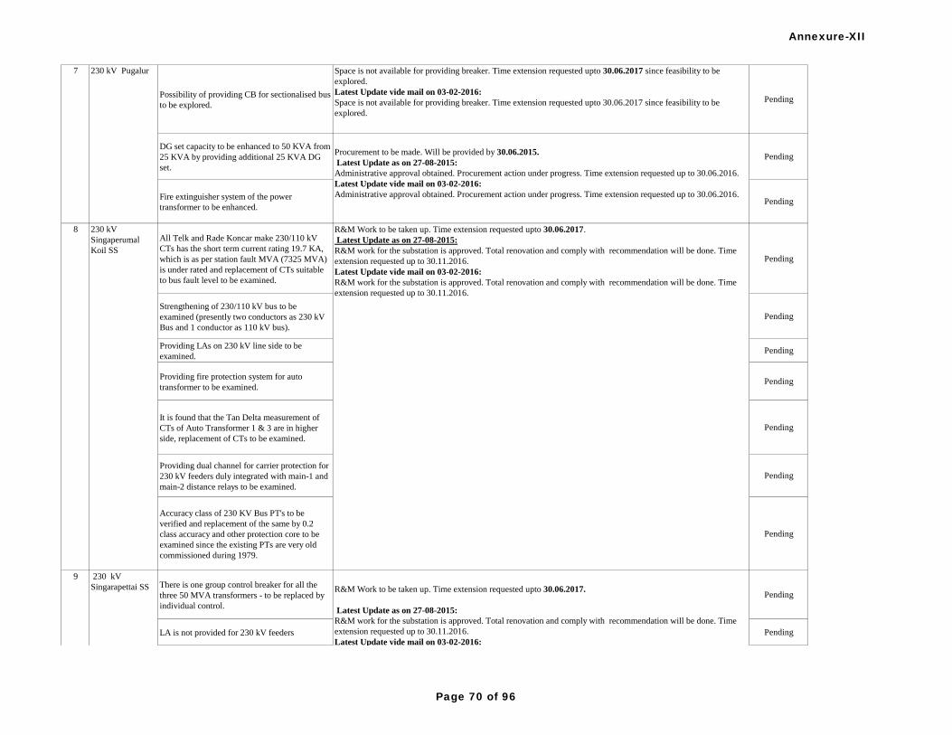
Possibility of providing CB for sectionalised bus
to be explored.
Space is not available for providing breaker. Time extension requested upto 30.06.2017 since feasibility to be
explored.
Latest Update vide mail on 03-02-2016:
Space is not available for providing breaker. Time extension requested upto 30.06.2017 since feasibility to be
explored.
Pending
DG set capacity to be enhanced to 50 KVA from
25 KVA by providing additional 25 KVA DG
set.
Pending
Fire extinguisher system of the power
transformer to be enhanced.Pending
All Telk and Rade Koncar make 230/110 kV
CTs has the short term current rating 19.7 KA,
which is as per station fault MVA (7325 MVA)
is under rated and replacement of CTs suitable
to bus fault level to be examined.
Pending
Strengthening of 230/110 kV bus to be
examined (presently two conductors as 230 kV
Bus and 1 conductor as 110 kV bus).
Pending
Providing LAs on 230 kV line side to be
examined.Pending
Providing fire protection system for auto
transformer to be examined.Pending
It is found that the Tan Delta measurement of
CTs of Auto Transformer 1 & 3 are in higher
side, replacement of CTs to be examined.
Pending
Providing dual channel for carrier protection for
230 kV feeders duly integrated with main-1 and
main-2 distance relays to be examined.
Pending
Accuracy class of 230 KV Bus PT's to be
verified and replacement of the same by 0.2
class accuracy and other protection core to be
examined since the existing PTs are very old
commissioned during 1979.
Pending
There is one group control breaker for all the
three 50 MVA transformers - to be replaced by
individual control.
Pending
LA is not provided for 230 kV feeders Pending
7 230 kV Pugalur
Procurement to be made. Will be provided by 30.06.2015.
Latest Update as on 27-08-2015:
Administrative approval obtained. Procurement action under progress. Time extension requested up to 30.06.2016.
Latest Update vide mail on 03-02-2016:
Administrative approval obtained. Procurement action under progress. Time extension requested up to 30.06.2016.
8 230 kV
Singaperumal
Koil SS
R&M Work to be taken up. Time extension requested upto 30.06.2017.
Latest Update as on 27-08-2015:
R&M work for the substation is approved. Total renovation and comply with recommendation will be done. Time
extension requested up to 30.11.2016.
Latest Update vide mail on 03-02-2016:
R&M work for the substation is approved. Total renovation and comply with recommendation will be done. Time
extension requested up to 30.11.2016.
9 230 kV
Singarapettai SS R&M Work to be taken up. Time extension requested upto 30.06.2017.
Latest Update as on 27-08-2015:
R&M work for the substation is approved. Total renovation and comply with recommendation will be done. Time
extension requested up to 30.11.2016.
Latest Update vide mail on 03-02-2016:
R&M work for the substation is approved. Total renovation and comply with recommendation will be done. Time
extension requested up to 30.11.2016.
Annexure-XII
Page 70 of 96

Single DC source is provided for breaker
operation. Additional source to be provided.Pending
10 230 kV Madurai
SS
LA is not available for the lines (230 kV &
below), Earth Resistance value not available.
Procurement to be made. Will be completed by 30.06.2016 .
Latest Update as on 27-08-2015:
Administrative approval obtained. Procurement action under progress. Time extension requested up to 30.06.2016.
Latest Update vide mail on 03-02-2016:
Administrative approval obtained. Procurement action under progress. Time extension requested up to 30.06.2016.
Pending
11 230 kV
Thiruvalam SS
Lightning Arresters are not provided on all 230
and 110KV feeders.
Procurement to be made. Will be completed by 30.06.2016.
Latest Update as on 27-08-2015:
Administrative approval obtained. Procurement action under progress. Time extension requested up to 30.06.2016.
Latest Update vide mail on 03-02-2016:
Administrative approval obtained. Procurement action under progress. Time extension requested up to 30.06.2016.
Pending
Provision of LAs at line entry for 230 kV
feeders to be considered.
Procurement to be made. Will be completed by 30.06.2016.
Latest Update as on 27-08-2015:
Administrative approval obtained. Procurement action under progress. Time extension requested up to 30.06.2016.
Latest Update vide mail on 03-02-2016:
Administrative approval obtained. Procurement action under progress. Time extension requested up to 30.06.2016.
Pending
Synchronous relay not available. Being done
manually.
Procurement to be made.Will be completed by 30.09.2015
Latest Update vide mail on 03-02-2016:
The issue was discussed in the special meeting of PCSC held on 19.08.2014, and the forum agreed to drop the Item. Pending
Availing tertiary connection to be explored for
auxiliary supply of station.
Already two sources available for station supply. Tertiary connection for auxiliary supply is not used in TN.
Latest Update as on 27-08-2015 and vide mail on 03-02-2016:
Loading of tertiary not in practice in TANTRANSCO. However Station supply from two sources are available.
Pending
In the 400 kV & 230 kV yard the following
observations were made. i) Earth mat was
designed and installed at the time of
commissioning only. There is no provision to
measure earth resistances. The Neutral of each
ICT have individual earth pit but there is no
provision to measure earth resistance and the
earth pits are not maintained at regular periods.
ii) The Mulsifire Systems are found to be not
installed properly. Also since installation, no
maintenance has been carried out.
Mulsifier system restoration will be taken up shortly. Estimate sanctioned for provision of 60 No earth pits
measurement of earth resistance. And work to be taken up. Time extension requested upto 31.03.2015.
Latest Update as on 27-08-2015 and vide mail on 03-02-2016:
Mulsifier system restoration will be taken up shortly. Estimate sanctioned for provision of 60 No earth pits
measurement of earth resistance and work to be taken up. Time extension requested up to 30.06.2016.
Pending
400 kV Alamathy
SS (IS) & 230 kV
Almatty SS
13
9 230 kV
Singarapettai SS R&M Work to be taken up. Time extension requested upto 30.06.2017.
Latest Update as on 27-08-2015:
R&M work for the substation is approved. Total renovation and comply with recommendation will be done. Time
extension requested up to 30.11.2016.
Latest Update vide mail on 03-02-2016:
R&M work for the substation is approved. Total renovation and comply with recommendation will be done. Time
extension requested up to 30.11.2016.
12 230 kV
Tondiarpet,
Chennai
Annexure-XII
Page 71 of 96

The existing 50 KVA DG set to be enhanced to
250 KVA.
Additional capacity to be procured. Will be provided by 31.03.2015.
Latest Update as on 27-08-2015 and vide mail on 03-02-2016:
Administrative approval obtained. Procurement action under progress. Time extension requested up to 30.06.2016.
Pending
Possibility of providing the Fire Protection wall
to 400/230 KV AUTO Transformer 2 to be
explored and AUTO Transformer 3 & 4 to be
heightened.
Fire protection wall will be hightened by 31.03.2015 for Auto 3&4. For Auto 2 space is not available .
Latest Update vide mail on 03-02-2016:
New Fire protection wall constructed for 400/230 KV Auto Transformer – II and heightening of existing Fire
protection wall work for 400/110 KV Auto Transformer – III & Auto Transformer – IV has been completed on
21.01.2016.
Complied
The tie CB of ICT 1 & 2 is kept in open
condition due to isolator mechanical problem
from last 6 months. Early action to be taken to
keep DIA in closed condition.
complied on 28.01.2013. Complied
Incorporating the status of station aux. system
like battery charger, dg set, IT a.c. etc in the
HMI shall be examined.
Feasibility discussed with SAS supplier. Estimate to be prepared for provision. Time extension requested upto
30.06.2016
Latest Update vide mail on 03-02-2016:
Feasibility discussed with SAS supplier. Estimate to be prepared for provision. Time extension requested upto
30.06.2016
Pending
Jelly spreading in the switchyard is insufficient. complied on 21.07.2014. Complied
It is suggested that providing separate dual DC
source to be examined. One set of dual DC
source for 400 kV side and second set of dual
DC source 230 kV and 110 kV side so that fault
in the dc system can be identified from where it
develops.
Dual DC source is available in the station. Separate DC panel available for each souece with MCBs for each circuit.
Hence identification of fault is possible with present arrangement.Complied
Fire protection system is not provided for ICTs.
Estimate sent for approval. Time extension requested upto 30.06.2015.
Latest Update vide mail on 03-02-2016:
Estimate sent for approval. Time extension requested upto 30.06.2016.
Pending
LAs on 230 kV line side is not provided.
Provision of LAs on 230 kV side to be
examined.
Procurement to be made. Will be completed by 30.06.2016
Latest Update vide mail on 03-02-2016:
Procurement to be made. Will be completed by 30.06.2016
Pending
In carrier aided protection, one channel is used.
Provision of dual channels integrated to main-1
& main-2 distance protection relay to be
examined.
Procurement to be made. Time extension requested upto 30.06.2016.
Latest Update as on 27-08-2015:
Administrative approval obtained. Procurement action under progress. Time extension requested up to 30.06.2016.
Latest Update vide mail on 03-02-2016:
Procurement action under progress. Time extension requested up to 30.06.2016.
Pending
The existing emulsifier system (for ICTs) meant
for fire extinction is not in service.
The existing emulsifier system (for ICTs) meant for fire extinction is to be reconditioned.Action being taken. Time
extension requested upto 30.06.2016.
Latest Update as on 27-08-2015:
New system with nitrogen extingusing system proposed and sent for approval. Time extension requested up to
30.06.2016.
Latest Update vide mail on 03-02-2016:
New system with nitrogen extingusing system proposed. Time extension requested up to 30.06.2016.
Pending
15 400 kV
Sunguvarchathira
m SS & 230 kV
Sunguvarachathir
am SS
16 400 kV
Sriperumbudur
14 400 KV K R
Thoppur SS -
Salem (230 KV
SS)
Annexure-XII
Page 72 of 96

It is suggested that providing separate dual DC
source to be examined. One set of dual DC
source for 400 kV side and second set of dual
DC source 230 kV and 110 kV side so that fault
in the dc system can be identified from where it
develops.
Dual DC source is available in the station. Separate DC panel available for each souece with MCBs for each circuit.
Hence identification of fault is possible with present arrangement.Complied
Centralised AC to be expedited for proper
functioning of protection system panels and to
prevent failure of numerical protection system.
Centralised AC made fully functional on 05.03.2014. Complied
LAs on 230 kV line side is not provided.
Provision of LAs on 230 kV side to be
examined.
Pending
Replacement of 25 years old gaped surge
surrestors with new gapless type for auto
transformers to be examined.
Pending
The three phase but fault level on 400 kV side is
21901 MVA and on 230 kV side is 15239
MVA. The fault current based on the above
fault level is 31.6 KA on 400 kV side and 38
KA on 230 KV side. The CTs and CBs which
are in service are having the rated SC capacity
of 40 KA which is almost on the verge.
Exploring the possibility of upgrading the
ratings of CBs and CTs are reducing the fault
level to be reviewed.
18300 MVA on 400kV side and 13398 MVA on 230kV side as on 31.3.2014. Hence upgradation of CBs and CTs
not required.Complied
S. No Name of
Substation Details of work Status of Implementation of Protection Audit Recommendations Remarks
S. No Name of
SubstationDetails of work Status of Implementation of Protection Audit Recommendations Remarks
The existing Main-1 (Electrostatic Quadramho)
Distance Relays should retrofitted with latest
version Numerical Relays for easy and quick
analysis of the faults.
Latest update as on 24-08-2015:
Complied by December 2014Complied
Static THR relay - Main-II Vallur - I & II feeder
has been replaced - retrofitted with REL 670 N
relay. Because of i) Ma-operation of Zone-2 and
Faulty. Ii) Mal-operation of Zone-3 and Zone-2
and Zone-3, tripping time delay might be kept
uniform throughout all feeders at Sriperubudur.
(Other Main Zone-1 other Zone tripping
including the reverse sign is not uniformly
adjusted and to be reviewed.)
Complied Complied230 kV
Sriperumbudur
S/S
1
16 400 kV
Sriperumbudur
Procurement to be made. Will be completed by 30.06.2016.
Latest Update as on 27-08-2015:
Administrative approval obtained. Procurement action under progress.Time extension requested up to 30.06.2016.
Latest Update vide mail on 03-02-2016:
Procurement action under progress. Time extension requested up to 30.06.2016.
Combined (Phase-I & Phase II)
KSEB
Phase-I
1 220 kV Areacode
S/S
Annexure-XII
Page 73 of 96

Over flux protection is not available 220/110
kV, 160 MVA Transformer.
Latest update as on 24-08-2015:
Complied by December 2014Complied
Main-2 relay is not available inall 220 kV
feeders. Only backup protection relays are
provided.
Latest update as on 24-08-2015:
Complied by December 2014.Complied
Protection couplers are not provided in 220 kV
AMBR 1 & 2 and 220 kV BRKL - 1 &2 feeders
AMBR feeders- complied. BRKL (renamed as COBR)- OPGW link to be established by PGCIL.
Latest update as on 24-08-2015:
Protection couplers are provided in BR KL renamed as COBR 1 & 2 feeders . Relay interfacing for COBR 1& 2
will be completed in 1 month.
Latest Update vide mail on 28-01-2016:
Complied by 10.2015
Complied
Ratio test on CTs are done at lower currents
only. Higher capacity not done due to non
availability of kits with sufficient capacity.
Under final stage of Procurement(Will be installed in Jan 2015)
Latest update as on 24-08-2015:
PO placed for new current injection kit of 200A.
Latest Update vide mail on 28-01-2016:
Injection Kit received
Complied
Separate DC ground fault annunciation (+ve to
GND & -ve to GND) to be provided.
Latest update as on 24-08-2015:
Complied by August 2014Complied
GPS & Event logger is not available.
PO issued.Will be issued by Jan 2015
Latest update as on 24-08-2015:
Completed by July 2015.
Complied
Zone 3 setting not common for all feeders.Latest update as on 24-08-2015:
Completed by Dec 2014Complied
Carrier inter tripping not available for SBEM 1,
2 & 3 feeders.
Latest update as on 24-08-2015:
Completed by Dec 2014Complied
Main 2 distance protection for EMPC 1 feeder
not available.
Latest update as on 24-08-2015:
Completed by Dec 2014Complied
LBB not in service for SBEM 2, 3 and EMPC 1Latest update as on 24-08-2015:
Completed by Dec 2014Complied
3 220 kV Edamon
SS
1 220 kV Areacode
S/S
2 220 kV
Brahmapuram
Substation
Annexure-XII
Page 74 of 96

LBB protection for all Circuit Breakers shall be
included.
Latest update as on 24-08-2015:
Completed by Dec 2014Complied
Automatic change over facildity shall be made
available for 110 V Switch Yard Battery system.
Latest update as on 24-08-2015:
Completed by March 2015Complied
Main-II Distance protection shall be propvided
for feeders
Latest update as on 24-08-2015:
Completed by Dec 2014Complied
Distance Relay with Quadrilateral
characteristics shall be provided for high
resistance faults
Latest update as on 24-08-2015:
Completed by Dec 2014Complied
All Electro Mechanical Relays to be replaced
with modern numerical relays.
Latest update as on 24-08-2015:
Completed by Dec 2014Complied
Main-2 relay is not provided on 220 kV BRKL-
1 feeder. Backup relays are provided in all
feeders
Latest update as on 24-08-2015:
Completed by Dec 2014Complied
Protection couplers are not provided in 220 kV
BRKL-1 & 2 feeders
Latest update as on 24-08-2015:
Protection couplers are provided in 220 kV COBR 1 & 2 feeders . Relay interfacing for COBR 1& 2 will be
completed in 1 month.
Latest Update vide mail on 28-01-2016:
Complied by 10.2015
Complied
CT ratio tests are done at lower currents only.
Higher capacity not done due to non-availability
of kits with sufficient capacity.
Under final stage of Procurement(Will be installed in Jan 2015)
Latest update as on 24-08-2015:
New current injection kit PO placed. Will get within 1 month.
Latest Update vide mail on 28-01-2016:
Injection Kit received
Complied
GPS & Event logger is not available.
PO issued.Will be issued by Jan 2015
Latest update as on 24-08-2015:
Completed by Dec 2014
Complied
4 220 kV Idukki
HEP
5 220 kV
Kalamassery
Substation
Remarks: Earth mat of 220 kV, 66kV switchyardsand the power house are interconnected and the total resistance
value is within safe limits.Due to difficult terrain of switchyard independent measurement of earth resistance is not
possible at present. The earth mat is already interconnected with tail race earthing system.The requirement of the
protection audit committee will be considered during renovation period. Would be considered during renovation
period (Recommended by PCSC forum)
Latest update as on 24-08-2015:
Earth mat of 220kV ,66kV switchyards and the power House are interconnected and the total resistance value is
within safe limits.Due to the difficult terrain of switchyard independent measurement of earth resistance is not
possible at present. The earth mat of Idukki HEP is made with Copper conductor and the earth mat is already
interconnected with tail race earthing system.
Latest Update vide mail on 28-01-2016:
The earth mat is already interconnected with tail race earthing system.
Provision for measuring earth resistance to be
explored.
Complied
Annexure-XII
Page 75 of 96

Bus-bar protection is not available. The same to
be provided.
Time extension requested.
Latest update as on 24-08-2015:
PO placed for bus bar protection panel and work scheduled to be completed befored 31.12.2015
Latest Update vide mail on 28-01-2016:
To be completed before 31.12.2016
Latest Update vide mail on 29-02-2016:
Purchase order placed.PO-22/15-16 dt.17.2.16 of Chief Engineer Transmission South to M/s.Danish. Material will
be received in April.So the work may be completed by 31.12.2016. While carrying out work, there are many critical
220kV feeders including interstate and feeders from GSs will have to switched off for long periods. The delay in
obtaining shutdown of these feeders may delays the work. So the time extension required up to 31.12.2016.
Pending
6 220 kV
Kaniyambetta S/SThe 220 kV line's Main I (Electrostatic
QUADRAMHO) Distance Relays should
retrofitted with latest version Numerical Relays
for easy and quick analysis of faults.
Latest update as on 24-08-2015:
Completed by Dec 2014Complied
7 220 kV
Madakkathara1 phase auto reclosing to be provided for 220
kV feeders.Complied Complied
Resistance reaches to be examined for each zone
of protection instead of setting it as a commoin
parameter as in the 220 kV New Pallom-
Kayamkulam 1 & 2.
Latest update as on 24-08-2015:
Completed by Nov 2014Complied
Load encroachment impedance and the
loadability of the relay to be examined
depending upon the line length and loading nof
the feeder.
Latest update as on 24-08-2015:
Completed by Nov 2014Complied
Providing of stub/EFP protection to be
examined for 220 kV lines.
It is informed that at 220 KV level stub protection is not provided. Bus PT is used for distance protection. KSEB
requested the item be dropped. The issue was discussed and the forum accepted the proposal.
The issue was discussed in the special meeting of PCSC held on 19.08.2014, and the forum agreed to drop the
Item.
Latest update as on 24-08-2015:
When line is switched off, line CB and bus isolator are kept open.Hence stub/EFP protection not required
Dropped
For 220 kV Busbar protection check zone to be
reviewed to take it from a separate PS class
core to have additional security to prevent
inadvertent tripping of bus zone protection due
to main core saturation.
Latest update as on 24-08-2015:
Numerical bus bar protection panel PO placed and scheduled to be completed before 31.12. 2015.
Latest Update vide mail on 28-01-2016:
Will be completed before 31.12.2016
Latest Update vide mail on 29-02-2016:
Purchase order placed.PO-21/15-16 dt.31.12.15 of Chief Engineer Transmission North, Kozhikode to M/s. G E
India Industrial Pvt. Limited Material will be received in April. So the work may be completed by
31.12.2016.While carrying out work, there are many critical 220kV feeders including interstate and feeders from GSs
will have to switched off for long periods. The delay in obtaining shutdown of these feeders may delays the work. So
the time extension required for this work is up to 31.12.2016
Pending
The carrier aided trip to be examined to have
different channel for main-1 and main-2
protection as twin channel is available in
protection coupler at different frequencies.
Latest update as on 24-08-2015:
Completed by Nov 2014Complied
8 220 kV New
Pallom Switching
Station
5 220 kV
Kalamassery
Substation
Annexure-XII
Page 76 of 96

Delay in operating time for zone-2 and zone-3 to
be reviewed to be set at 350ms and 800ms
respectivedly as per SRPC & PGCIL direction,
otherwise ensure setting to be identical for both
local and remote end.
Latest update as on 24-08-2015:
Completed by Nov 2014Complied
Enabling functionality for both main-1 and main-
2 relay to be reviewed.
Latest update as on 24-08-2015:
Completed by Nov 2014Complied
220 kV Idukki-New Pallom feeder has main-1
static version relay and main-2 has overcurrent
relay which to be considered to be replaced with
numerical distance protection relay.
Latest update as on 24-08-2015:
Completed by Nov 2014Complied
Relay settings of LBB to be checked and
corrected as per norms.Complied Complied
Back-up relay in service in all 220 kV feeders Complied Complied
Main-2 relay and PLCC are not available in all
220 kV ELPK-1 and ELPK-2 feeders. Complied Complied
CVT ratio is beyond permissible limit in R and
Y phases of ELPK-2 and Bus-1 CVTComplied Complied
Load encroachment impedance and the
loadability of the relay to be examined
depending upon the line length and loading nof
the feeder.
Latest update as on 24-08-2015:
Completed by Nov 2014Complied
Providing of stub/EFP protection to be
examined for 220 kV lines.
It is informed that at 220 KV level stub protection is not provided. Bus PT is used for distance protection. KSEB
requested the item be dropped. The issue was discussed and the forum accepted the proposal.
The issue was discussed in the special meeting of PCSC held on 19.08.2014, and the forum agreed to drop the
Item.
Latest update as on 24-08-2015:
When line is switched off, line CB and bus isolator are kept open.Hence stub/EFP protection not required
Dropped
Possibility of providing different make
distancve protection relay for main-1 and main-2
protection to be explored.
Latest update as on 24-08-2015:
Completed by Nov 2014Complied
The carrier aided trip to be examined to have
different channel for main-1 and main-2
protection as twin channel is available in
protection coupler at different frequencies.
Latest update as on 24-08-2015:
Completed by Nov 2014Complied
Enabling functionality for both main-1 and main-
2 relay to be reviewed.
Latest update as on 24-08-2015:
Completed by Nov 2014Complied
220 kV Sabarigiri-Pallom feeder protection is
proposed to be replaced with numerical relay
protection system may6 be expedited.
Latest update as on 24-08-2015:
Completed by Nov 2014Complied
8 220 kV New
Pallom Switching
Station
9 220 kV Palakkad
S/S
10 220 kV Pallom
Annexure-XII
Page 77 of 96

Constructing of oil sump adjacent to the
transformer at suitable location to be explored
for collecting of oil in the case fire brokes out in
the case of emergencies.
WO issued. Will be done by Jan 2015.
Latest update as on 24-08-2015:
Work in progress and scheduled to be completed before 30.09. 2015.
Latest Update vide mail on 28-01-2016:
Completed by 10-2015
Complied
10 220 kV Pallom
Annexure-XII
Page 78 of 96

UFR setting needs to be changed as per
recommended setting.
Latest update as on 24-08-2015:
Completed by Dec 2014Complied
Galvanizing to be done for the supporting
structures in the 220 kV switchyard.
Latest update as on 24-08-2015:
Completed by April 2014Complied
Some of the CTs error is found above he
recommende value. Retesting is required.
Latest update as on 24-08-2015:
Completed by Dec 2014Complied
Control Panel for transformer 1 & 2 numerical
relay to be provided.
Latest update as on 24-08-2015:
Completed by Feb 2015.Complied
Earth resistance value is found to be on higher
side. Remedial measures shall be taken.
Exploring proper measurement provision.(Time extension recommended by PCSC forum)
Latest update as on 24-08-2015:
Done- Found 0.42ohms
Complied
Even though two 110 V DC sources available,
redundancy for protection system not ensured.
Latest update as on 24-08-2015:
Cable laying & terminal connections pending and scheduled to be completed before 30.09.2015.
Latest Update vide mail on 28-01-2016:
Completed by 10-2015
Complied
48V DC positive earthing not proper in the
carrier communication panel and also
redundancy not ensured.
Latest update as on 24-08-2015:
Completed by Dec 2014Complied
Main-II independent distance relay not available
for all the lines.
Latest update as on 24-08-2015:
Completed by Mar 2015Complied
Line distance relays zone-3 and zone-4 settings
are found to be same but timings are different.
Latest update as on 24-08-2015:
Completed by Dec 2014Complied
Some of the isolators not able to be operated
from SCADA PC.
Latest update as on 24-08-2015:
Completed by Dec 2014Complied
66/11 kV, 4MVA Transformer CB closing voil
taking 50A approximately for operation, hence it
shall be replaced.
New CB to be installed taking care of space constraints. (Time extension recommended by PCSC forum)
Latest update as on 24-08-2015:
Breaker received. Erection will be completed before 31.05.2016.
Latest Update vide mail on 28-01-2016:
Completed by 12-2015
Complied
High resistance fault are frequent in these lines,
so lines tripping on back up E/F protection for
the in zone line fault. It shall be avoided by
providing carrier aided earth fault protection.
Latest update as on 24-08-2015 and vide mail on 28-01-2016:
Resistance coverage of distance relays have been revised. Presently high resistance faults are detected by distance
relays. So immediate implementation of carrier aided earth fault protection for DEF is not required.
Pending
LBB protection pickup current is less so it is to
be compared with line charging current and set
above it and LBB time delay to be reduced.
Latest update as on 24-08-2015:
Completed by Dec 2014Complied
S. No Name of
SubstationDetails of work Status of Implementation of Protection Audit Recommendations Remarks
1 220 kV Areacode
S/SPossibility of using separate DC Sources for
Main-1 & Main-2 to be explored for reiability of
DC supply.
Latest update as on 24-08-2015:
Complied by June 2015Complied
11 220 kV
Pothencode
12 220 kV Sabarigiri
Moozhiyar HEP
Phase-II
Annexure-XII
Page 79 of 96

DG set is not available in the station.
PO issued.Will be issued by Jan 2015
Latest update as on 24-08-2015:
Completed by July 2015.
Complied
The % error in some of the CVTs found to be
high and there is proposal for replacing them.Complied Complied
Substation is under renovation hence earth pits
shall be incorporated.
Latest update as on 24-08-2015:
New earthmat provided in the 220kV yard. Complied
DG set not available.
PO issued.Will be issued by Jan 2015.
Latest update as on 24-08-2015:
DG set erection completed Commissioning will be done before 31-08-15.
Latest Update vide mail on 28-01-2016:
Completed by 12.2015
Complied
48 V dc supply redundancy not available.Latest update as on 24-08-2015:
Complied by Dec 2014.Complied
Only one bus available, transfer bus shall be
provided.
Design and tendering in progress.
Latest update as on 24-08-2015 and vide mail on 28-01-2016:
Administrative Sanction accorded for 25 crores . Tender procedures started and the work scheduled to be
completed before 31.12.2016.
Latest Update vide mail on 29-02-2016:
1.Tender process in progress (Price bid opened awaiting Board sanction for proceeding further) and the completion
date may extent up to 31.12.2016. While carrying out work, the inter state feeders namely Thirunelveli No I & II
feeders will have to switched off for long periods. The delay in obtaining shutdown of these feeders may delays the
work. The time of completion may be extended up to 31.12.2016
Pending
Fire protection operation with electrical sensor
shall be provided for generator transformers.
To be carried out during renovation.(Recommended by PCSC forum)
Latest update as on 24-08-2015:
PO placed for new current injection kit of 200A.
Latest Update vide mail on 28-01-2016:
Included in R&M work
Latest Update vide mail on 29-02-2016:
This work has been scheduled for execution along with the proposed R&M of first stage units of Idukki HEP. The
tender invited for the R&M work has been cancelled and is being retendered. The time of completion may be
extended to 31.3.2017.
Pending
In some of the CTs, the ratio errors are found to
be in higher side. It shall be checked and
corrective measures to be taken.
Latest update as on 24-08-2015:
The CTs were tested with meters and test kit of high accuracy and error found within limits. December 2014Complied
Bus bar protection is not available.
Design and tendering in progress.
Latest update as on 24-08-2015:
Tender invited for bus bar protection panel and scheduled to be completed before 31.05.2016.
Latest Update vide mail on 28-01-2016:
PO placed for new bus bar protection Panel.Will be completed by 30.6.2016.
Latest Update vide mail on 29-02-2016:
PO issued for Busbar protection Panel & 220KV CTs . .PO-13/15-16 dt.16.11.15 of Chief Engineer
Transmission North, Kozhikode to M/s. DANISH Pvt. Limited .Material will be received in March. Work can be
completed wihin one month from the date of receipt of balance materials.
Pending
DG Set is not available.Latest update as on 24-08-2015:
Complied by Nov 2014.Complied
3 220 kV Edamon
SS
4 220 KV Idukki
HEP
5 220 kV
Kaniyambetta S/S
2 220 kV
Brahmapuram
Substation
Annexure-XII
Page 80 of 96

Only one set of Battery charger and battery set is
available.
Latest update as on 24-08-2015:
Complied by Nov 2014.Complied
Transfer breaker scheme to be examined for
substitution of main breaker.
Due to space constraints KSEB requested to drop the item. The PCSC forum discussed the issue and suggested to
have a bus Sectionaliser scheme instead of transfer bus scheme. KSEB agreed for the suggestion.
The PCSC forum (Special Meeting
of Protection Co-Ordination Sub-Committee (PCSC)
held at SRPC, Bangalore on 19.08.2014) agreed to send the proposal to Hon’ble CERC for consideration and
allowing KSEB to implement the bus Sectionaliser scheme.
Latest update as on 24-08-2015:
Not possible due to space constraints
Dropped
DG set is not available for emergency purpose
for LT source and a 250 kVA DG set is
suggested to be installed as a commom external
electrical power source for both New Pallom
and Pallom sub-stations.
Under Progress
Latest update as on 24-08-2015:
Common DG set for Pallom and New Pallom Substations and erection scheduled to be completed before
30.9.2015.
Latest Update vide mail on 28-01-2016:
Complied by 9/2015
Complied
Earth mat to be provided for Pallom 220 kV sub-
station to have effective earthing.
Design and tendering in progress.
Latest update as on 24-08-2015:
Work in progress and scheduled to be completed before 31.12. 2015.
Latest Update vide mail on 28-01-2016:
Will be completed by 5/2016
Pending
220 kV Busbar protection & LBB protection are
not there at Pallom 220 kV sub-station and it is
suggtested to add up 220 kV numerical busbar
protection & LBB protection to prevent severe
damage to equipments and ultimate financial
loss.
Design and tendering in progress.
Latest update as on 24-08-2015:
Numerical bus bar protection panel PO placed and scheduled to be completed before 31.12. 2015.
Latest Update vide mail on 28-01-2016:
Will be completed by 31.12.20016
Latest Update vide mail on 29-02-2016:
PO placed. PO-21/15-16 dt.31.12.15 of Chief Engineer Transmission North, Kozhikode to M/s. G E India
Industrial Pvt. Limited Material will be received in April and scheduled to be completed before 31.12. 2016.
Pending
DG set is not available for emergency purpose
for LT source and a 250 kVA DG set is
suggested to be installed as a commom external
electrical power source for both New Pallom
and Pallom sub-stations.
PO issued.Will be installed in Jan 2015.
Latest update as on 24-08-2015:
Common DG set for Pallom and New Pallom Substations and erection scheduled to be completed before
30.9.2015.
Latest Update vide mail on 28-01-2016:
Complied by 9/2015
Complied
Compact size bus coupler [PASS (PLUG AND
SWITCHED SYUSTEM) - HYBRID
SWITCHGEAR] proposal to be considered for
flexibility of operation and reliability to the 220
kV source for the station.
Design and tendering in progress.
Latest update as on 24-08-2015:
Tendering in progress. Work scheduled to be completed before 31.03 2016.
Latest Update vide mail on 28-01-2016:
Will be completed by 31.12.20016
Latest Update vide mail on 29-02-2016:
PO will be issued soon after getting approval of purchase committee. Work scheduled to be completed before 31.12
2016.
Pending
5 220 kV
Kaniyambetta S/S
6 220 kV New
PallomSwitching
Station
7 220 kV Pallom
S/S
Annexure-XII
Page 81 of 96

8 220 kV
Pothencode
Double Bus arrangement is required for 110 kV
switchyard
Design and tendering in progress.
Latest update as on 24-08-2015:
Lay out finalised.Work to be tendered and scheduled to be completed before 31.07.2017.
Latest Update vide mail on 28-01-2016:
Will be completed by 31.12.2017.
Latest Update vide mail on 29-02-2016:
Due to space constraints in yard , 110 kV CT-CB hybrid unit is being explored for 200 MVA, Transformer bays.
Administrative sanction awaited from Board. The process time of material purchase of the above work will also take
one year. So the over all time to complete the above work may extended up to 31.12.2017.
Pending
9 220 KV Sabarigiri
Moozhiyar HEP
Bus-I & II current carrying capacity is around
1600A, which is not sufficient hence Bus MVA
capacity shall be reviewed by considering the
bus fault level.
Weak portions of the bus conductors replaced during total shutdown of the station during May-June 2014.Extensive
S/D is required for total replacement of conductor.Will be carried out as early as possible.
Latest update as on 24-08-2015 and vide mail on 28-01-2016:
DPR prepared and scheduled to be completed before 31.5.2016.
Latest Update vide mail on 29-02-2016:
DPR prepared will be submitted to NLDC for availing PSDF sanction and scheduled to be completed before
31.12.2017.
Pending
10 400 kV
Madakkathara
substation Fire hydrant system to be provided. Complied Complied
S. No Name of
SubstationDetails of work Status of Implementation of Protection Audit Recommendations Remarks POWERGRI
D SR I / II1 400 KV Arasur
SubstationDistance protection Zone-2 & Zone-3 timing of
230 KV feeders need review complied Complied
POWERGRI
D SR II
2 400 kV Bidadi
Substation Synchronisation check relay setting is to be
reviewed.
Latest Update as on 24-08-2015:
Settings reviewed and implemented.Complied
POWERGRI
D SR II
Enabling of stub protection in Ramagundam-3
& 4, Kurnool feeders Scheme implemented in the new numerical realys during retrofitting. Complied
Replacement of static relays by Numerical Relay
provided for Distance, Differential Bus Bar and
Reactor Protection
All distance relays are retrofitted with Numerical protection relays. Complied
Static differential relays to be replaced with
numerical relays on reactors and ICTsAll distance relays are retrofitted with Numerical protection relays. Complied
Electromagnetic back up directional O/C and
E/F relays to be replaced with numerical relays
on ICT-1.
PGCIL informed that the relay is healthy and not mal operated. PGCIL also informed the existing static relays are
meeting all protection requirements of the bus bar relay as per CBIP guidelines. PGCIL requested that the item be
dropped.
The issue was discussed in the special meeting of PCSC held on 19.08.2014, and the forum agreed to drop the
Item.
Latest Update as on 24-08-2015:
All Differential relays are retrofitted with Numerical protection relays.
Dropped
3 400 kV Ghanapur
(Hyderabad)
SubstationPOWERGRI
D SR I
4 400 kV Gooty
Substation
POWERGRI
D SR I
PGCIL
Phase-I
Annexure-XII
Page 82 of 96

Old PLCC protection couplers to be replaced
with new protection couplers
Action for replacement of Protection coupler initiated and is in process. Schdld by end of Jan'15.
Latest Update as on 24-08-2015:
The PLCC of Nsagar feeder has been replaced with ETL41. For Bangalore feeder the NSD 60 of Channel-I is
replaced with NSD50.
Complied
5 400 kV HassanBased on Setting of distance protection relays to
be reviewed as per the revised line parameters
received from KPTCL.
Latest Update as on 24-08-2015:
Settings based on revised line parameters adopted in both relays.Complied
POWERGRI
D SR II
Static distance relays of 400 kV feeders to be
replaced with numerical relays All the (03 nos.) LZ 96 relays in 400kV lines replaced in Dec-12. Complied
Static bus bar protection relay to be replaced
with numerical relays
Existing busbar protection relay complies to all CBIP guidelines. This matter was discussed in previous PCC
meetings and this point was removed. The Bus Bar protection is healthy and in line with CBIP guidelines/gazette
standards. Hence the same was not replaced.
Dropped
8 400 kV
Kalivanthapattu
S/S
230 kV feeder distance protection Zone-2 and
Zone-3 timings need review
Latest Update as on 24-08-2015:
Changed to 350ms/800ms.Complied
POWERGRI
D SR II
9
230 kV
Kalivanthapattu
S/S
230 kV feeder Zone-2 and Zone-3 trip timings
are 250 m sec and 500 m sec. where as in TNEB
it is 350 m sec and 800 m sec. This may be
looked into.
Complied CompliedPOWERGRI
D SR II
10 400 KV
Khammam
Substation
Old Static line protection (Distance) relays to be
replaced with numerical relays
Latest Update as on 24-08-2015:
All distance relays are retrofitted with Numerical protection relays.Complied
POWERGRI
D SR I
11 400 kV
MadakkatharaTime synchronising of protection system with
GPS to be providedcomplied Complied
POWERGRI
D SR II
Replacement of static relays (THR, CAG,
RADHA etc.) with numerical relays to be
looked into.
Latest update as on 24-08-2015:
Replacement completed in 400kV lines. 220kV lines are carried out by May 13.Complied
4 400 kV Gooty
Substation
POWERGRI
D SR I
6 400 kV Hiriyur
Substation
POWERGRI
D SR II
12 400 kV Mysore
Substation
POWERGRI
D SR II
PGCIL informed that the relay is healthy and not mal operated. PGCIL also informed the existing static relays are
meeting all protection requirements of the bus bar relay as per CBIP guidelines. PGCIL requested that the item be
dropped.
The issue was discussed in the special meeting of PCSC held on 19.08.2014, and the forum agreed to drop the
Item.
Latest Update as on 24-08-2015:
1. All Differential relays are retrofitted with Numerical protection relays.
2. Numerical Busbar protection is not envisaged as per Gazzett notifications.
3. O/V feature is implemented in Ditance protection relays during the retrofitting of the relays.
Electromagnetic and static relays for ICTs,
Reactor, Bus bar,over voltage, distance
protection to be replaced with numerical relays.
400 kV Kadapa
Substation
7
Dropped POWERGRI
D SR I
Annexure-XII
Page 83 of 96

Co-ordination of protection settings for 220 kV
Downstream lines to be done to avoid un
wanted trippings at Mysore SS.
Latest update as on 24-08-2015:
Reviewed and Revised.Complied
Plug setting multiplier setting of back up over
current relays of CTs to be reviewed.
Latest update as on 24-08-2015:
Reviewed and found ok.Complied
Distance protection Zone-2 and Zone-3 timings
of 220 KV lines need review
Latest update as on 24-08-2015:
Reviewed and revised.Complied
Bus sectionaliser direction to be reviewed (both
sides operation).
Latest update as on 24-08-2015:
The direction was kept based on the faulty history and discussed in 18PCSC meeting.Complied
Zone-2 & Zone-3 time settings of distance
protection relays of 230kV feeders need review.
Latest update as on 24-08-2015:
The revised time settings as per approved settings implemented.Complied
LBB & Bus Bar protection are in-built in the
same Siemens SIPROTEC 75552 Relay for both
Main 1 & 2. Same needs review
PGCIL informed that separate LBB and Bus Bar protection schemes are not specified in the CBIP guidelines. Hence
PGCIL requested for dropping the item. The PSCS forum discussed the issue and accepted the request.
The issue was discussed in the special meeting of PCSC held on 19.08.2014, and the forum agreed to drop the
Item.
Dropped
15 400 kV PugalurDistance protection zone-2 and zone-3 time
settings for 230 kV Lines needs review.complied Complied
POWERGRI
D SR II
16 400 kV Salem
Substation Static distance protection relays of 400 kV
feeders to be replaced with numerical relays
Latest update as on 24-08-2015:
All static distance protection relays has been replaced with numerical relays.Complied
POWERGRI
D SR II
Nomenclature of Binary Inputs/Binary Outputs
& function to be done in DR.
Latest update as on 24-08-2015:
In feeder,already ensured. In transformers, will be done during next ICTs S/D.
The issue was discussed in PCSC-51 held on 25-02-2016 held on 25-02-2016, when PGCIL (SR-II) informed that
the Nomenclature of Binary Inputs/Binary Outputs & function had been completed for transformers also.
Complied
The high set setting of HV side DOCR & DEFR
of each 500 MVA Transformer needs review.
Latest update as on 24-08-2015:
All T/F settings have been reviewed and found OK.Complied
18 400 kV Trichy
Substation Old electromagnetic/static relays to be replaced
with numerical relays.
Latest update as on 24-08-2015:
All four (04) distance relays have been replaced with numerical relays in Jan 13.Complied
POWERGRI
D SR II
Old Static line protection (Distance) relays to be
replaced with numerical relays.All distance relays are retrofitted with Numerical protection relays. Complied
Evaluation unit is to be made available for
Disturbance recorder of 400 KV Vemagiri-I & II
feeders.
DR PC installed and configured for collecting data from DR. Complied
13 400 KV Narendra
Substation
POWERGRI
D SR II
14 400 kV
Puducherry
Substation & 230
kV Puducherry
Substation
POWERGRI
D SR II
12 400 kV Mysore
Substation
POWERGRI
D SR II
17 400 kV
Somanahalli
Substation
POWERGRI
D SR II
19 400 KV
Vijayawada
(NUNNA)
Substation
POWERGRI
D SR I
Annexure-XII
Page 84 of 96

The DRs (Indactic65C) and Event Logger
(SER7000) of 400KV VTPS-I & II Feeders are
not healthy and need to rectified.
The DRs ( Indactic65C) and Event Logger ( SER7000) of 400KV VTPS-I&II feeders are not working (Belongs to
APTRANSO & being persued with APTRANSCO).
Latest update as on 24-08-2015:
DR & EL PCs installed and configured for collecting data.
Complied
Monitoring source to be provided for DC earth
leakage to be provided
Latest update as on 24-08-2015:
The faulty cables have been addressed and presently DC Earth fault is not present in the system.Complied
Over voltage protection time setting to be
reviewed complied Complied
Review of zone-3 setting for 220kV Kochi-
Brahmapura and 220kV Kochi-Kalamashery complied Complied
21 400kV Munirabad
Substation Numerical relay to be provided for differential
protection of ICT-1&2complied Complied
POWERGRI
D SR I
Old relays to be replaced with numerical relays
for feeders, ICTs and Reactors.
Latest Update as on 24-08-2015:
All Differential relays are retrofitted with Numerical protection relays.Complied
Mutual compensation to be incorporated in
distance protection settings of 400kV N'Sagar-
Ramagundam ckt-1&2.
Latest Update as on 24-08-2015:
During retorifitting of relays the Mutual compensation is carried out.Complied
S. No Name of
SubstationDetails of work Status of Implementation of Protection Audit Recommendations Remarks
POWERGRI
D SR I / II
1 400 kV Kochi SS
220V Battery bank-1&2 for protection system to
be replaced with lead acid batteries
VRLA batteries are inline with the standard guidelines.
The issue was discussed in PCSC-47 held on 15.09.2015, and the forum agreed to drop the Item.
DroppedPOWERGRI
D SR II
2 400 kV Palakkad
SS Outsource supply supplied from 11 kV Para
feeder is having low reliability and hence
alternate arrangements to be made for reliable
supply.
Latest Update as on 24-08-2015:
The tertiary supply from ICT#2 erection completed. Request for availing aux supply is being processed by KSEB.
The issue was discussed in PCSC-51 held on 25-02-2016 when PGCIL (SR-II) informed that they have started
availing supply from the tertiary of ICT # 2 from 3rd week of Jan, 2016.
CompliedPOWERGRI
D SR II
3 400 kV Trichy SS
Existing 50 V set-1 Batteries to be enhanced to
adequate capacity. Same to be replaced
Latest Update as on 24-08-2015:
The 50 V set 1 commissioning has been completed on 15-01-13.Complied
POWERGRI
D SR II
4 400 KV
Vijayawada
(Nunna) SS
Fire fighting system is out of service for
replacement of old damaged pipe line.
All the works on Fire fighting system at Vijayawada are completed. Presently the Fire Fighting system is functional
and put into service and the same is in Auto mode since 01/03/2014. Communication sent vide letter dtd 28/04/14Complied
POWERGRI
D SR I
S. No Name of
SubstationDetails of work Status of Implementation of Protection Audit Recommendations Remarks
1400 kV Gajuwaka
S/S (IS)
LZ96 and RAZFE relays are being replaced with
numerical relays having DR facility.Complied Complied
20 400kV Kochi
SubstationPOWERGRI
D SR II
22 400kV N'Sagar
(Tallapalli)
SubstationPOWERGRI
D SR I
19 400 KV
Vijayawada
(NUNNA)
Substation
POWERGRI
D SR I
Combined (Phase-I & Phase-II)
Phase-II
Annexure-XII
Page 85 of 96

2
HVDC Kolar S/SArrangements may be made to replace the
battery
electrolyte level indicators wherever not proper
Complied Complied
S. No Name of
SubstationDetails of work Status of Implementation of Protection Audit Recommendations Remarks
Distrubance Recorders (ABB, INDACTIC) not
having GPS time synchronisation (for 400 kV
Warangal Line, 400 kV Gajwel Line, 400 kV
Malkaram Line, 400 kV Hyderabad Line # 3,
400 kV Hyderabad Line # 4), 400 kV Dichipalli
Numerical relay (DR) not having GPS time
synchronisatiion.
a) These disturbance recorders are connected to a PC. The PC has now been time synchronized through GPS. The
PC synchronizes the DRs with the batch process (WINCOM) on regular basis. - Complied
b) 400 kV Dichipalli Numerical relay (DR): Time synch problem has been taken up with TSTRANSCO, the owner
of the equipment.
The issue with regard to time synchronisation of Dichipally feeders numerical relay was discussed in PCSC-51 held
on 25-02-2016 and it was made clear that the responsibility of complying with this recommendations lies with
TSTRANSCO.
Complied
Distrubance recorder of 400 kV Nagarjunasagar-
2 sent for repair. However, built-in DR
available with the relay MICOM442.
The disturbance recorder installed. Complied
DC supply-II: +ve to Earth voltage measured is
158 V, -ve to Earth voltage measured is -80 V.Ongoing routine activity Complied
Over current & earth fault protection enabled in
Chandrapur - 1 & 2 and N'Sagar 1 & 2 as per
instructions of NTPC CC (Mail copy verified)
The Overcurrent protection is active only in case of VT fuse fail condition. This is in line with present protection
philosophy.Complied
CT ratio test results for Dichipalli (Tie & Main),
Auto-5 (Main & Tie), Auto-4 (Main & Tie),
Hyderabad-2 (Main & Tie), Hyderabad-1 (Main
& Tie), Warangal (Main & Tie), Main & Tie Cts
of Gen-1, Gen-3, Tie-1, Tie-2 will be submitted
to SRPC, Bangalore by NTPC Ramagundam
subsequently.
All the data has been sent to SRLDC in the first week of Dec, 2012. Complied
CVT test results for Warangal, Auto-1, 2, 3 & 4
and Hyderabad 3 & 4 will be submitted to
SRPC, Bangalore by NTPC Ramagundam
subsequently.
Submitted to SRLDC in the first week of Dec, 2012 Complied
NTPC Ramagundam has confirmed that copy of
recommended/adopted relay settings for all the
feeders will be submitted to SRPC, Bangalore
subsequently.
Submitted to SRLDC in the first week of Dec, 2012 Complied
2400 kV NTPC
Simhadri S/S
(Gen)
NTPC informed that the existing MICROMHO
relays of Stage-I lines are being replaced with
REL 670 relay of ABB make which will be
integrated to ABB Micro SCADA of Stage-2.
Complied Complied
NTPC
(Phase I & II)
400 kV NTPC
Ramagundam S/S
(Gen)
1
Annexure-XII
Page 86 of 96

3
220 kV NTPC
Kayamkulam S/S
(Gen)
Zone-2 and Zone-3 relays may be considered to
be adopted as 350 ms and 800 ms as per the
SRPC directions, otherwise zone-2 & zone-3
timing may be adopted uniformly at both ends -
local end & remote end.
Complied Complied
PLCC facility for protection is not available for
220 kV lines
OPTCL is the owner of the associated PLCC system of the 220 kV Lines. The scheme for PLCC aided tripping for
220 Kv Lines is in place at Kaniha but non functional due to absence of protection coupler in associated PLCC
system.
OPTCL may be pursued to provide protection coupler in the associated PLCC system.
Pending
Auto reclosing feature is not available in all 220
kV lines
The scheme of Auto reclosing function for 220 Kv lines is in place at Kaniha end. This feature is non-functional due
to absence of protection coupler in the assoclated PLCC system.OPTCL may be pursued to provide protection
coupler in the associated PLCC system.
Pending
Static relays may be replaced with numerical
relaysThe Main- II distance protection Relays of 400 Kv Rourkela D/C have been replaced with numerical relays. Complied
Earth switches are not provided for Talcher-
Rourkela 400 kV line I & II and Talcher-Rengali
400 kV line I & II to facilitate earthling during
maintenance.
The line earthing is achieved through the corresponding Tie bay isolators. Complied
S. No Name of
Substation Details of work Status of Implementation of Protection Audit Recommendations Remarks
The line relays 220 KV side are provided with
01 primary protection ie. Static Relay, and a
back up relay is to electro mechanical relay with
high set. Blocking of High set protection in the
back up relay needs to be reviewed. NPCIL-
Kaiga to review the same
Completed during May 2014 Complied
Instead of Static Relays, Numerical Relays to be
provided with different make for all lines as
Main-I and Main-II. NPCIL-Kaiga to review the
same
Completed Complied
The test reports of CT, CVT & CB are to be
furnished.Complied Complied
The stability test conducted was confirmed
orally however no records could be verifiedComplied Complied
Synchronizing relay details to be furnished. Complied Complied
Latest Tested dates of Line protection Relays
MI, MII, LBB & PLCC are to be furnishedComplied Complied
220 KV Kaiga-
Generating
Station-1&2
NPCIL
(Phase I & II)
230KV MAPS
Kalapakkam S/S
(Gen)
2
400kV Talcher
STPS, NTPC
4
1
Annexure-XII
Page 87 of 96

Line Parameters for Acharpakkam & Bhavini
are yet to be furnished.Yet to be furnished. Pending
Recommended line protection relay settings
with the latest fault levels and the adapted
settings could not be verified. The revised
recommendations & copy of adapted relay
settings to be submitted by MAPS, NPCIL
Complied Complied
The Line CVT in the Y phase of the feeder was
not available in all the feeders except SP koil 2 :
To be reviewed
Communicated to TANTRANSCO.
The issue was discussed in PCSC-51 held on 25-02-2016, and it was made clear that the responsibility of complying
with this recommendations lies with MAPS (NPCIL).
Pending
S. No Name of
SubstationDetails of work Status of Implementation of Phase I Recommndations Remarks
Protection system to be synchronized with
available GPS Complied Completed
Event logger to be rectified and made functional Complied Completed
Disturbance Recorder to be rectified and made
functionalComplied Completed
Existing micro mho distant protection (Main I)
relays to be retrofitted with numerical relay.Complied Completed
2 400 kV NLC TPS-
II Expn.O/V protection for stage-II time setting to be
revised for instantaneous tripComplied Completed
S. No Name of
SubstationDetails of work Status of Implementation of Protection Audit Recommendations Remarks
NLC
Phase-I
1 400 kV NLC TPS-
I Expn.
230KV MAPS
Kalapakkam S/S
(Gen)
2
Phase-II
Battery bank to be provided for OPGW will fulfil the 2nd source requirement.Completed by 31.04.2015
Latest Update as on 08-08-2015:
Expected date of completion is 31-12-2015.
Latest Update as on 24-08-2015:
Order has been placed for second 48V DC source in OPGW package being implemented by PGCIL, which is
expected to complete by 31-Dec-2015.
Latest Update as on 22-09-2015:
Battery bank to be provided for OPGW will fulfil the 2nd source requirement. Supply of battery bank in PGCIL's
scope. PGCIL has informed NLC that the work would be
completed before 31.12.2015. It was informed that the two pending phase-II activities will be completed before
31.12.2015 as prayed in NLC's affidavit dt. 05.09.2015.
Latest Update vide mail on 07-01-2016:
Battery bank to be provided for OPGW by PGCIL will fulfil the 2nd source requirement. Materials are received at
site. Erection works will be taken up shortly. Expected date of completion is Before 30.06.2016.
The issue was discussed in PCSC-51 held on 25-02-2016, when NLC informed that the second source for 48 V
PLCC battery system was commissioned in the 3rd week of February, 2016. It was also informed through an email
dated 26-02-2016.
2nd source for 48 V PLCC battery system to be
considered.
400 kV
Switchyard - NLC
TPS-II Expn.
1
Complied
Annexure-XII
Page 88 of 96

Battery bank to be provided for OPGW will fulfil the 2nd source requirement.Completed by 31.04.2015
Latest Update as on 08-08-2015:
Expected date of completion is 31-12-2015.
Latest Update as on 24-08-2015:
Order has been placed for second 48V DC source in OPGW package being implemented by PGCIL, which is
expected to complete by 31-Dec-2015.
Latest Update as on 22-09-2015:
Battery bank to be provided for OPGW will fulfil the 2nd source requirement. Supply of battery bank in PGCIL's
scope. PGCIL has informed NLC that the work would be
completed before 31.12.2015. It was informed that the two pending phase-II activities will be completed before
31.12.2015 as prayed in NLC's affidavit dt. 05.09.2015.
Latest Update vide mail on 07-01-2016:
Battery bank to be provided for OPGW by PGCIL will fulfil the 2nd source requirement. Materials are received at
site. Erection works will be taken up shortly. Expected date of completion is Before 30.06.2016.
The issue was discussed in PCSC-51 held on 25-02-2016, when NLC informed that the second source for 48 V
PLCC battery system was commissioned in the 3rd week of February, 2016. It was also informed through an email
dated 26-02-2016.
2nd source for 48 V PLCC battery system to be
considered.
400 kV
Switchyard - NLC
TPS-II Expn.
1
Complied
Purchase action in progress. Work will be completed by 31.03.2015.Latest Status is by 30.09.2015.
Latest Update as on 08-08-2015:
Expected date of completion is 31-12-2015.
Latest Update as on 24-08-2015:
Purchase action initiated and expected to be completed before 31.12.2015.
Latest Update as on 22-09-2015:
Purchase action in advanced stage of completion. P.O. likely to be issued in October-2015 and erection and
commissioning will be taken up in Nov-Dec 2015. Work will be completed by 31.12.2015.
It was informed that the two pending phase-II activities will be completed before 31.12.2015 as prayed in NLC's
affidavit dt. 05.09.2015.
Latest Update vide mail on 07-01-2016:
Purchase Order issued to vendor. Expected date of completion is before 30.06.2016.
The issue was discussed in PCSC-51 held on 25-02-2016, when NLC informed that the second source for 48 V
PLCC battery system was commissioned in the 3rd week of February, 2016. It was also informed through an email
dated 26-02-2016.
Only one bank of 48V battery for PLCC is
available. 2nd bank to be provided
400 kV
Switchyard - NLC
TPS-I Expn.
2
Complied
Annexure-XII
Page 89 of 96

S. No Name of
SubstationDetails of work Status of Implementation of Protection Audit Recommendations Remarks
1
400 kV JSWEL
S/S (Gen) The over voltage stage - 2 and stub protection
functions for 400 kV lines may please be
enabled for better protection schemes.
Complied Complied
It is observed that 400 kV BuS voltage is on the
higher side since from the commissioning of
400 kV Hassan-Udipi line 1,2. Action needs to
be taken to reduce the stress on the equipment.
VAR compensation is suproted by the Generator. Complied
The extension of permissive trip to Hassa SS in
the event of O/V trip also at Udipi end needs to
be verified & rectified at Udipi end.
Complied Complied
Based on the revised line parameters received
from KPTCL, new settings adopted in Main-
1&2 relays during October 2012.
Complied Complied
DC Main battery, +ve ground is observed & the
same may be rectified.Attended Complied
The distance protectio-Main-I and Main-II and
busbar protection - periodic testing not
conducted so far from commissioning. The same
may be tested immediately for the healthyness of
the above system.
Attended Complied
PLCC / Protection Coupler not in service. The
same may be put into service.Attended Complied
OTHERS
(Phase I & II)
2
400 kV UPCL S/S
(Gen)
3
220 kV ITPL S/S
220 kV Spectrum
PGL S/S (Gen)
4
Dropped
APTRANSCO requested that item be dropped considering that the relays are only provided on the identified feeder,
and not for all substations. The issue was discussed in the special meeting of PCSC held on 19.08.2014, and the
forum accepted the proposal.
The issue was discussed in the special meeting of PCSC held on 19.08.2014, and the forum agreed to drop the
Item.
Spectrum mail recieved on 15-09-2015:
We plan to replace 220 KV Spectrum-Kakinada line distance
Protection relays with two different make numerical protection relays with lEC 61850 compatibility during our
Renovation &Modemization activity in December 2015. We have received quotes for the said relays of make
Alstom, ABB and siemens. Siemens offered model nos-SIPROTEC 47SA6 and 47SA522. The Technical
specifications of Alston and ABB relays are enclosed here with . Basing on your recommendations and
approvals, we shall proceed further to procure the relays.
Spectrum mail recieved on 19-10-2015:
We plan to replace 220 KV Spectrum-Kakinada line distance
Protection relays with two different make numerical protection relays with lEC 61850 compatibility during our
Renovation &Modemization activity in December 2015. We have received quotes for the said relays of make Alstom
and ABB and we are in the process of procurement of the relays.
It is observed that there is no O/V protection,
df/dt & UFR protection for both the 220 kV
feeders.
Annexure-XII
Page 90 of 96

PLCC inter trip protection is not in service for
both feeders.
Spectrum mail received on 15-09-2015 and 19-10-2015:
Carrier inter tripping scheme of SPGL-Kakinada lines 1 &2 has been tested in co-o rdina tlon with MRT team,
Rajahmundry and kept in service.Complied
GPS is not available.
Spectrum mail received on 15-09-2015 and 19-10-2015:
Disturbance recorder and Event logger are available presently. But the Time Synchronization facility for global
common time reference will be studied and implemented in December 2015 during R&M of our plant.
Spectrum Mail received on 27-01-2016 and 23-02-2016:
We have been evaluating technical specifications of two different make numerical distance relays with IEC 61850
compatibility. We will install these numerical distance relays positively, during our Plant Renovation &
Modernisation in APRIL-2016. These two relays will provide the GPS facility.
Pending
220 kV Spectrum
PGL S/S (Gen)
4
Dropped
APTRANSCO requested that item be dropped considering that the relays are only provided on the identified feeder,
and not for all substations. The issue was discussed in the special meeting of PCSC held on 19.08.2014, and the
forum accepted the proposal.
The issue was discussed in the special meeting of PCSC held on 19.08.2014, and the forum agreed to drop the
Item.
Spectrum mail recieved on 15-09-2015:
We plan to replace 220 KV Spectrum-Kakinada line distance
Protection relays with two different make numerical protection relays with lEC 61850 compatibility during our
Renovation &Modemization activity in December 2015. We have received quotes for the said relays of make
Alstom, ABB and siemens. Siemens offered model nos-SIPROTEC 47SA6 and 47SA522. The Technical
specifications of Alston and ABB relays are enclosed here with . Basing on your recommendations and
approvals, we shall proceed further to procure the relays.
Spectrum mail recieved on 19-10-2015:
We plan to replace 220 KV Spectrum-Kakinada line distance
Protection relays with two different make numerical protection relays with lEC 61850 compatibility during our
Renovation &Modemization activity in December 2015. We have received quotes for the said relays of make Alstom
and ABB and we are in the process of procurement of the relays.
It is observed that there is no O/V protection,
df/dt & UFR protection for both the 220 kV
feeders. Annexure-XII
Page 91 of 96

For 220 kV line # 2 protection relay
recommended settings to be adopted.
GMR mail received on 09-09-2015:
Settings are adopted as per recommendations and relay calibrated. Complied
a) Distance protection Zone: 4 time of operating
t 1 pp adopted: 1.2 sec; Recommended 0.9 sec
GMR mail received on 09-09-2015:
As per telephonic advice by DE power system the settings retained as same because this was envisage and corrected
during commissioning by AP Transco Officials with concern of DE power System.
GMR mail received on 28-01-2015:
GMR have submitted a letter to APTRANSCO seeking the permission to issue an Approval for setiings
recommended by the protection audit team.
GMR mail received on 08-02-2016:
Settings as per CE-IPC & Power System.
The issue was discussed in PCSC-51 held on 25-02-2016 and the forum had agreed to the settings adopted by GMR
as suggested to them by APTRANSCO. And the item was dropped.
Dropped
b) Power swing detection I base current
adopted: 3000 A; Recommended: 800 A
GMR mail received on 09-09-2015:
Base current changed to 800 A.Complied
c) Time delayed phase overcurrent protection
(18) Adopted: ON; Recommended: OFF
GMR mail received on 09-09-2015:
Kept in OFF.Complied
d) Time delayed phase overcurrent protection
(18) Adopted: ON; Recommended: OFF
GMR mail received on 09-09-2015:
Kept in OFF.Complied
e) Time delayed over voltage protection (24)
Adopted: ON; Recommended: OFF
GMR mail received on 09-09-2015:
Kept in OFF.Complied
f) Synchro check (29) Adopted: ON;
Recommended: OFF
GMR mail received on 09-09-2015:
As per telephonic advice by DE power system the settings retained as same because this was envisage and corrected
during commissioning by AP Transco Officials with concern of DE power System.
GMR mail received on 28-01-2015:
GMR have submitted a letter to APTRANSCO seeking the permission to issue an Approval for setiings
recommended by the protection audit team.
GMR mail received on 08-02-2016:
GMR informed that they would adopt the recommended setting in presence of APTRANSCO officials.
Pending
For 220kV Line #2 Distance protection Zone: 4
time of operating t1 pp Adopted: 1.2 sec;
Recommended : 0.9 sec
GMR mail received on 09-09-2015:
As per telephonic advice by DE power system the settings retained as same because this was envisage and corrected
during commissioning by AP Transco Officials with concern of DE power System.
GMR mail received on 28-01-2015:
GMR have submitted a letter to APTRANSCO seeking the permission to issue an Approval for setiings
recommended by the protection audit team.
GMR mail received on 08-02-2016:
Settings as per CE-IPC & Power System.
The issue was discussed in PCSC-51 held on 25-02-2016 and the forum had agreed to the settings adopted by GMR
as suggested to them by APTRANSCO. And the item was dropped.
Dropped
Auto reclose scheme is kept in OFF position for
both 400 kV feeders.
GVK mail received on 16-09-2015:
Auto re-closure scheme was enabled and kept in service at 400KV Gautami SS end as per approved settings of
APTRANSCO, confirmation of the same was communicated to APTRANSCO CE (Power Systems) in Jan 2013.
Complied
In 220 kV line # 1, main # 1 & 2 protection relay following deviations observed:
220 kV GMR
Barge, Kakinada
S/S (Gen)
400 kV GVK
Gautami S/S
(Gen)
6
5
Annexure-XII
Page 92 of 96

Over voltage stage-1 time setting of line-2 is
deviating from recommended setting i.e.
recommended setting is 5 sec & adopted setting
is 4 sec.
GVK mail received on 16-09-2015:
Relay settings for over voltage protection were revised as per the ref. letter #4.Complied
It is observed that there is no under frequency
and df/dt protections for both 400 kV feeders.
APTRANSCO requested that item be dropped considering that the relays are only provided on the identified feeder,
and not for all substations. The issue was discussed in the special meeting of PCSC held on 19.08.2014, and the
forum accepted the proposal.
The issue was discussed in the special meeting of PCSC held on 19.08.2014, and the forum agreed to drop the
Item.
Dropped
Recommended relay settings are not available
with the utility
Reliance mail received on 18-09-2015:
Recommended relay settings were implemented on 02/05/2015, in the presence of MRT Wing, APTRANSCO,
Bommur
Complied
Main-I protection zone settings are deviating
with recommended settings as per record of M/s.
Reliance.
Reliance mail received on 18-09-2015:
Recommended relay settings were implemented on 02/05/2015, in the presence of MRT Wing, APTRANSCO,
Bommur
Complied
PLCC Inter Tripping Scheme was not in service.
Reliance mail received on 18-09-2015:
PLCC Inter tripping was taken into service, on 02/05/2015, in the presence of MRT Wing & Telecom Wing,
APTRANSCO.
Complied
O/V, U/F & df/dt protections are not available
for both the feeders.
APTRANSCO requested that item be dropped considering that the relays are only provided on the identified feeder,
and not for all substations. The issue was discussed in the special meeting of PCSC held on 19.08.2014, and the
forum accepted the proposal.
The issue was discussed in the special meeting of PCSC held on 19.08.2014, and the forum agreed to drop the
Item.
Dropped
Over current relay High. Set value of STGT is
9.5 instead of 7.5
KGPL mail received on 19-09-2015:
The Over current relay High-Set value of STGT has been changed from 9.5 to 7.5.Complied
Over voltage stage-1 time delay setting is 4 sec
instead of 5 sec in 400 kV Line #2.
KGPL mail received on 19-09-2015:
Over voltage stage-1 time delay setting of 400kV line-2 has been changed from 4sec to 5 sec.Complied
Observed Auto reclose selection is in non auto
mode for both the 400 kV feeders
KGPL mail received on 19-09-2015:
To implement Auto-reclosure scheme for 400kV Line 1 and 2 Breakers technical support is required from OEM who
have supplied the line protection relays and communication is in progress with them. After getting support from
OEM, Auto-reclosure scheme implementation period will be informed.
Pending
Observed there is no U/F & df/dt functions for
both the 400 kV feeders
APTRANSCO requested that item be dropped considering that the relays are only provided on the identified feeder,
and not for all substations. The issue was discussed in the special meeting of PCSC held on 19.08.2014, and the
forum accepted the proposal.
The PCSC forum agreed to drop the item.
Dropped
Auto reclosing scheme is in off condition for
both Line-1 and Line-2.
GVK mail received on 15-09-2015:
AttendedComplied
400 kV GVK
Gautami S/S
(Gen)
6
220 kV Reliance,
Samalkot S/S
(Gen)
7
400 kV
Konaseema S/S
(Gen)
8
400 kV GVK
Jegurupadu Extn.
S/S &
220 kV
Jegurupadu Extn.
S/S (Gen)
9
Annexure-XII
Page 93 of 96

O/V Stage-1 protection setting is observed at
115% (73V) instead of recommended 110%
(70V)
GVK mail received on 15-09-2015:
AttendedComplied
Overvoltage stage-1 protection was disabled in
Main-1 protection relays of both the 400 kV
feeders.
GMR mail received on 14-09-2015:
Enabled in Main-I protection relay for both 400kV feeders and complaince was submitted to CE/ Power System vide
letter dated 30th Sept, 2013.
Complied
Over voltage stage-2 was deviating from
recommended setting. (settings: Adopted Valve:
133V, 50 Milli seconds, recommended valve: 77
V, 0 sec.
GMR mail received on 14-09-2015:
Over voltage Stage-2 setting was revised as per CE/Power Systems and same was tested with the help of external
agency for correct operation and complaince submitted vide letter dated 30th Sep,2013.
Complied
Over voltage protection configuration Main 1
protections of both the feeders were deviating
from recommended configuration, i.e.
recommened is phase to neutral, adopted is
phase to phase.
GMR mail received on 14-09-2015:
Over voltage protection configuration Main-1 protections of both feeders were corrected as per initial approved
settings (i.e, Phase to Neutral)
Complied
Auto reclosure scheme was kept in non Auto
mode for both the 400 kV feeders.
GMR mail received on 14-09-2015:
Auto Scheme for both 400kV feeders was kept in Auto mode.Complied
All the Numerical Protection relays are not time
synch as the GPS is not available.Complied
All the Main-1 & Main-2 relays are showing
different timings.Complied
It was observed that over voltage stage 1 in
Main-1 relays of both the feeders are tested at
120.89V, but as per the relay setting it is in
disable condition.
GMR mail received on 14-09-2015:
Over voltage stage-1 in Main-1 relay settings was enabled for both feeders and same was tested as per setting with
the help of external agency for correct operations.
Complied
Power swing detection settings are deviating
from recommended settings (recommended is
1.0 OHM adopted is 0.5 OHM)
GMR mail received on 14-09-2015:
Power swing detection settings were corrected as per approved settings.Complied
GT Generator Transformer over current & high
set values are deviating from recommended
values (over current Recom. Set: 0.6, adopted
set point: 1 and high set recom. Set is 4.5,
adopted set 4)
GMR mail received on 14-09-2015:
GT Gernerator Transformer over current and high set values was corrected as per approved settings.Complied
As the recommended settings for Main 2
Protection relays are not available for both the
400 kV feeder relays, those were not verified.
GMR mail received on 14-09-2015:
Recommended settings for Main-2 Protection relays were available and same checked for correctness, it as per
approved settings.
Complied
All distance static relays should be retrofitted
with latest version Distance Relays for quick
and accurate analysis for the tripping.
APGPCL mail receieved on 14-09-2015:
Procurement is under progress.
APGPCL mail received on 29-01-2016:
Procurement action for numerical distance protection relays(Siemens make Siprotech relays, Type: 7SA522-5CB92-
5HR5/LOR and ABB make REL 670 model relays) with time sync is intiated and got delayed due to chennai fluds.
The same are expected to received & Commissioned by end of May 2016 and complience will be sent.
Pending
11
400 kV GMR
Vemagiri S/S
(Gen)
220 kV
Vijjeswaram
Stage-I S/S (Gen)
GMR mail received on 14-09-2015:
All the numerical relays time was corrected and GPS installation feasebility checks are under progress. The expected
date of installation and commisiioing of the GPS system for protection relays is 31 Oct, 2015.
GMR mail received on 02-02-2016:
Complied by 21st December, 2015
400 kV GVK
Jegurupadu Extn.
S/S &
220 kV
Jegurupadu Extn.
S/S (Gen)
9
10
Annexure-XII
Page 94 of 96
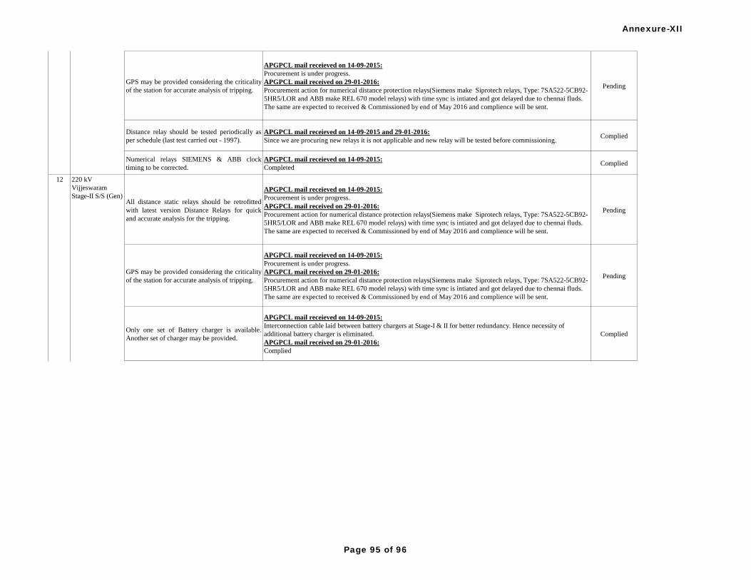
GPS may be provided considering the criticality
of the station for accurate analysis of tripping.
APGPCL mail receieved on 14-09-2015:
Procurement is under progress.
APGPCL mail received on 29-01-2016:
Procurement action for numerical distance protection relays(Siemens make Siprotech relays, Type: 7SA522-5CB92-
5HR5/LOR and ABB make REL 670 model relays) with time sync is intiated and got delayed due to chennai fluds.
The same are expected to received & Commissioned by end of May 2016 and complience will be sent.
Pending
Distance relay should be tested periodically as
per schedule (last test carried out - 1997).
APGPCL mail receieved on 14-09-2015 and 29-01-2016:
Since we are procuring new relays it is not applicable and new relay will be tested before commissioning.Complied
Numerical relays SIEMENS & ABB clock
timing to be corrected.
APGPCL mail receieved on 14-09-2015:
CompletedComplied
All distance static relays should be retrofitted
with latest version Distance Relays for quick
and accurate analysis for the tripping.
APGPCL mail receieved on 14-09-2015:
Procurement is under progress.
APGPCL mail received on 29-01-2016:
Procurement action for numerical distance protection relays(Siemens make Siprotech relays, Type: 7SA522-5CB92-
5HR5/LOR and ABB make REL 670 model relays) with time sync is intiated and got delayed due to chennai fluds.
The same are expected to received & Commissioned by end of May 2016 and complience will be sent.
Pending
GPS may be provided considering the criticality
of the station for accurate analysis of tripping.
APGPCL mail receieved on 14-09-2015:
Procurement is under progress.
APGPCL mail received on 29-01-2016:
Procurement action for numerical distance protection relays(Siemens make Siprotech relays, Type: 7SA522-5CB92-
5HR5/LOR and ABB make REL 670 model relays) with time sync is intiated and got delayed due to chennai fluds.
The same are expected to received & Commissioned by end of May 2016 and complience will be sent.
Pending
Only one set of Battery charger is available.
Another set of charger may be provided.
APGPCL mail receieved on 14-09-2015:
Interconnection cable laid between battery chargers at Stage-I & II for better redundancy. Hence necessity of
additional battery charger is eliminated.
APGPCL mail received on 29-01-2016:
Complied
Complied
11
220 kV
Vijjeswaram
Stage-II S/S (Gen)
12
220 kV
Vijjeswaram
Stage-I S/S (Gen)
Annexure-XII
Page 95 of 96
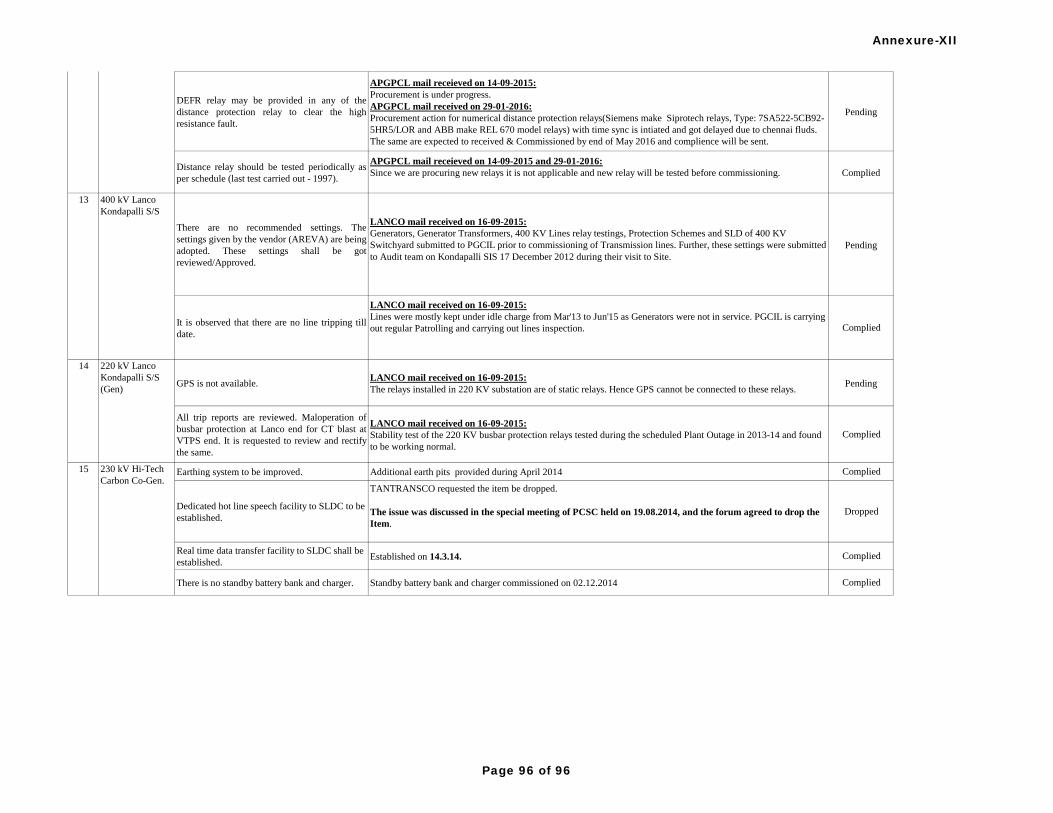
DEFR relay may be provided in any of the
distance protection relay to clear the high
resistance fault.
APGPCL mail receieved on 14-09-2015:
Procurement is under progress.
APGPCL mail received on 29-01-2016:
Procurement action for numerical distance protection relays(Siemens make Siprotech relays, Type: 7SA522-5CB92-
5HR5/LOR and ABB make REL 670 model relays) with time sync is intiated and got delayed due to chennai fluds.
The same are expected to received & Commissioned by end of May 2016 and complience will be sent.
Pending
Distance relay should be tested periodically as
per schedule (last test carried out - 1997).
APGPCL mail receieved on 14-09-2015 and 29-01-2016:
Since we are procuring new relays it is not applicable and new relay will be tested before commissioning. Complied
There are no recommended settings. The
settings given by the vendor (AREVA) are being
adopted. These settings shall be got
reviewed/Approved.
LANCO mail received on 16-09-2015:
Generators, Generator Transformers, 400 KV Lines relay testings, Protection Schemes and SLD of 400 KV
Switchyard submitted to PGCIL prior to commissioning of Transmission lines. Further, these settings were submitted
to Audit team on Kondapalli SIS 17 December 2012 during their visit to Site.
Pending
It is observed that there are no line tripping till
date.
LANCO mail received on 16-09-2015:
Lines were mostly kept under idle charge from Mar'13 to Jun'15 as Generators were not in service. PGCIL is carrying
out regular Patrolling and carrying out lines inspection. Complied
GPS is not available.LANCO mail received on 16-09-2015:
The relays installed in 220 KV substation are of static relays. Hence GPS cannot be connected to these relays.Pending
All trip reports are reviewed. Maloperation of
busbar protection at Lanco end for CT blast at
VTPS end. It is requested to review and rectify
the same.
LANCO mail received on 16-09-2015:
Stability test of the 220 KV busbar protection relays tested during the scheduled Plant Outage in 2013-14 and found
to be working normal.
Complied
Earthing system to be improved. Additional earth pits provided during April 2014 Complied
Dedicated hot line speech facility to SLDC to be
established.
TANTRANSCO requested the item be dropped.
The issue was discussed in the special meeting of PCSC held on 19.08.2014, and the forum agreed to drop the
Item.
Dropped
Real time data transfer facility to SLDC shall be
established.Established on 14.3.14. Complied
There is no standby battery bank and charger. Standby battery bank and charger commissioned on 02.12.2014 Complied
220 kV
Vijjeswaram
Stage-II S/S (Gen)
12
400 kV Lanco
Kondapalli S/S
13
15 230 kV Hi-Tech
Carbon Co-Gen.
14 220 kV Lanco
Kondapalli S/S
(Gen)
Annexure-XII
Page 96 of 96