Embed Size (px)
Citation preview
Refer to the service manual in the GSPN(see the rear cover) for the more information.
AIR CONDITIONER CONTENTS
SYSTEM AIR CONDITIONEROUTDOOR UNIT
AM036FXMDCH
AM048FXMDCH
AM053FXMDCH
AM060MXMDCH
1. Precautions
2. Product Specifications
3. Disassembly and Reassembly
4. Troubleshooting
5. PCB Diagram
6. Wiring Diagram
7. Reference Sheet
Section 0
Samsung Electronics 1
Contents
■. Precautions .............................................................................................................1 1-1 Precautions for the Service...........................................................................................................................................1
1-2 Precautions for the Static Electricity and PL ..........................................................................................................1
1-3 Precautions for the Safety .............................................................................................................................................1
1-4 Precautions for Handling Refrigerant for Air Conditioner ...............................................................................2
1-5 Precautions for Welding the Air Conditioner Pipe .............................................................................................2
1-6 Precautions for Additional Supplement of Air Conditioner Refrigerant ...................................................2
1-7 Other Precautions ............................................................................................................................................................2
■. Product Specifications ...........................................................................................3 1. The Feature of Product .....................................................................................................................................................3
1-1 Feature .......................................................................................................................................................................3
2. Product Specifications ......................................................................................................................................................9
■. Disassembly and Reassembly ............................................................................ 10 1. Necessary Tools ................................................................................................................................................................. 10
2. Disassembly and Reassembly ..................................................................................................................................... 11
2-1. AM036/048/053FXMDCH ............................................................................................................................... 11
2-2. AM060MXMDCH ................................................................................................................................................ 20
■. Troubleshooting ................................................................................................. 30 1. Error Display ....................................................................................................................................................................... 30
2. Error Code............................................................................................................................................................................ 31
3. Appropriate Measures for Different Symptom .................................................................................................... 33
3-1. Error due to repeated address setting (E-108) ....................................................................................... 33
3-2. Communication error between indoor and outdoor unit (E-201) ................................................ 34
3-3. Communication error on all PBA within the outdoor unit C-Box,
communication cable error. (E-205) ............................................................................................................ 36
3-4. Error on outdoor temperature sensor of outdoor unit (Short or open). (E-221) ...................... 37
3-5. Error on COND OUT temperature sensor of main outdoor unit (Short or open). (E-231) .... 38
3-6. Error on discharge temperature sensor of compressor 1 (Short or open). (E-251) ................. 39
3-7. Discharge temperature sensor of compressor 1 is detached from the sensor holder
on the pipe. (E-262) / Top sensor of compressor 1 is detached (E-266) .......................................... 40
3-8. Suction temperature sensor is detached from the sensor holder on the pipe. (E-269) ........ 41
3-9. Refrigerant leakage or error on high pressure sensor (Short or open). (E-291) ........................ 42
3-10. Refrigerant leakage or error on low pressure sensor (Short or open). (E-296) ....................... 43
3-11. Error on suction temperature sensor (Short or open). (E-308) ..................................................... 44
3-12. Error on temperature sensor of double layer pipe/
liquid pipe(sub heat exchanger) (Short or open). (E-311) ................................................................ 45
3-13. Error on EVI (ESC) IN temperature sensor (Short or open). (E-321) ............................................. 46
3-14. Error on EVI (ESC) OUT temperature sensor(Short or open). (E-322).......................................... 47
3-15. Error due to operation failure of Fan1 (E-446) ....................................................................................... 48
3-16. Lock error on Fan1 of outdoor unit. (E-448) ........................................................................................... 50
3-17. Error due to overheated motor of outdoor unit's Fan1. (E-453) ..................................................... 51
3-18. Error due to overheated IPM of Fan1. (E-455) ........................................................................................ 52
3-19. Output current sensor error of inverter PBA 1. (E-468) /
Error due to input current of inverter 1. (E-485) / ................................................................................ 53
3-20. DC voltage sensor error of inverter PBA 1. (E-469) ............................................................................ 54
3-21. Compressor operation stop due to high pressure protection control. (E-407) ..................... 55
Section 0
2 Samsung Electronics
Contents
3-22. Compressor operation stop due to low pressure protection
control or refrigerant leakage. (E-410) ..................................................................................................... 56
3-23. Compressor operation stop due to discharge temperature protection control. (E-416) .. 58
3-24. Phase reversal or phase failure(3Ø outdoor unit wiring, R-S-T-N),
connection error on 3 phase input. (E-425) ........................................................................................... 60
3-25. Phase reversal or phase failure(3Ø outdoor unit wiring, R-S-T-N),
connection error on 3 phase input. (E-428) ........................................................................................... 62
3-26. EVI (ESC) EEV leakage or internal leakage of intercooler or incorrect connector
insertion of EVI (ESC) EEV. (E-438) .............................................................................................................. 64
3-27. Error due to refrigerant leakage. (E-439) /
Operation prohibited due to low pressure. (E-443) ............................................................................ 66
3-28. Heating mode restriction due to high air temperature. (E-440) /
Operation prohibited due to low pressure. (E-441) ............................................................................ 67
3-29. Refrigerant charging restriction in heating mode
when air temperature is over 15°C. (E-442) ........................................................................................... 68
3-30. CCH is detached. (E-445) .............................................................................................................................. 69
3-31. Error due to operation failure of inverter compressor 1. (E-461) ................................................. 70
3-32. Error due to operation failure of inverter compressor 1. (E-464) ................................................. 71
3-33. Error due to over voltage / low voltage of inverter PBA 1. (E-466).............................................. 72
3-34. Error due to overheat caused by contact failure on IPM of inverter PBA 1. (E-500) ............. 73
3-35. Outdoor unit’s option switch setting error. (E-560) .......................................................................... 74
■. PCB Diagram and Parts List ............................................................................... 75 1. Outdoor Unit PCB ............................................................................................................................................................ 75
■. Wiring Diagram ................................................................................................... 83 1 AM036/048/053FXMDCH .................................................................................................................................................. 83
2. AM060MXMDCH .............................................................................................................................................................. 84
■. Reference Sheet................................................................................................... 85 1. Refrigerant cycle diagram ............................................................................................................................................. 85
1-1. AM036/048/053FXMDCH ............................................................................................................................... 85
1-2. AM060MXMDCH ................................................................................................................................................ 86
2. Nomenclatures .................................................................................................................................................................. 87
■. Check Operation & Amount of Refrigerant Automatically Checking ............ 88 1. Check Operation ............................................................................................................................................................... 88
1-1. Check Operation ................................................................................................................................................ 88
1-2. How to troubleshoot of the "Undetermined" ........................................................................................ 90
2. Automatic refrigerant amount detection function (Checking th amount of refrigerant) .................. 97
Samsung Electronics 1
■ Precautions
1. Precautions for the Service
Use the correct parts when changing the electric parts.
– Please check the labels and notices for the model name, proper voltage, and proper current for the electric parts.
Fully repair the connection for the types of harness when repairing the product after breakdown.
– A faulty connection can cause irregular noise and problems.
When disassembling or assembling, make sure that the product is laid down on a work cloth.
– Doing so will prevent scratching to the exterior of the rear side of the product.
Completely remove dust or foreign substances on the housing, connection, and inspection parts when performing repairs.
– This can prevent fire hazards for tracking, short, etc.
Please tighten the service valve of the outdoor unit and the valve cap of the charging valve as securely as possible by using
a monkey spanner.
Check whether the parts are properly and securely assembled after performing repairs.
– These parts should be in the same condition as before the repair.
2. Precautions for the Static Electricity and PL
Please carefully handle the PCB power terminal during repair and measurement when it is turned on since it is vulnerable
to static electricity.
– Please wear insulation gloves before performing PCB repair and measurement.
Check if the place of installation is at least 2m away from electronic appliances such as TV, video players, and stereos.
– This can cause irregular noise or degrade the picture quality.
Please make sure the customer does not directly repair the product.
– Arbitrary dismantling may result in electric shock or fire.
3. Precautions for the Safety
Do not pull or touch the power plug or the subsidiary power switch with wet hands.
– This may result in electric shock or fire.
If the power line or the power plug is damaged, then it must be changed since this is a hazard.
Do not bend the wire too much or position it so that it can be damaged by a heavy object on top.
– This may result in electric shock or fire.
The use of multiple electric outlets should be prohibited.
– This may result in electric shock or fire.
Ground the connection if it is necessary.
– The connection must be grounded if there is any risk of electrical short due to water or moisture.
Unplug the power or turn off the subsidiary power switch when changing or repairing electrical parts.
– Doing so will prevent electric shock.
– Although the power is off, Inverter PBA and Fan PBA are dangerous because they are charged with high DC voltage.
– Changing, checking and touching PBA are dangerous because of high DC voltage. So, please turn off the power and wait for
discharging DC voltage. ( To discharging DC voltage naturally, wait for more than 15 minutes.)
Explain to workers that the battery for the remote control needs to be separated for storage purposes when
the product will not be used for a long time.
– This can cause a problem for the remote control since battery fluid may trickle out.
2 Samsung Electronics
4. Precautions for Handling Refrigerant for Air Conditioner
Environmental Cautions: Air pollution due to gas release
Safety Cautions
If liquid gas is released, then body parts that come into contact with it may experience frostbite/blister/numbness.
If a large amount of gas is released, then suffocation may occur due to lack of oxygen. If the released gas is heated, then noxious
gas may be produced by combustion.
Container Handling Cautions
Do not subject container to physical shock or overheating. (Flowage is possible while moving within the regulated pressure.)
5. Precautions for Welding the Air Conditioner Pipe
Dangerous or flammable objects around the pipe must be removed before the welding.
If the refrigerant is kept inside the product or the pipe, then remove the refrigerant prior to welding.
If the welding is carried out while the refrigerant is kept inside, the welding cannot be properly performed. This will also produce
noxious gas that is a health hazard. This leakage will also explode with the refrigerant and oil due to an increase in the refrigerant
pressure, posing a danger to workers.
Please remove the oxide produced inside the pipe during the welding with nitrogen gas.
Using another gas may cause harm to the product or others.
6. Precautions for Additional Supplement of Air Conditioner Refrigerant
Precisely calculate the refrigerant by using a scale and S-net, and proceed with the test operation.
Excessive supplement can cause harm to the product since it can cause an inflow of the liquid refrigerant into the compressor.
Do not heat the refrigerant container for a forced injection.
This may cause harm to the product or others since the refrigerant container may burst.
Do not operate the product after removing the product safety pressure switch and sensor.
If the product is blocked inside, then this may cause harm to the product or others due to the excess pressure increase of the
refrigerant gas.
7. Other Precautions
There should be no leakage of the pipes after installation. When withdrawing the refrigerant, the compressor should be
stopped before removing the connecting pipe.
If the compressor is operating while the refrigerant pipe is not correctly connected and the service valve is opened, then
air and other substances can enter the pipe. The interior of the refrigerant cycle may then build up excessive high pressure
resulting in explosion and damage.
Samsung Electronics 3
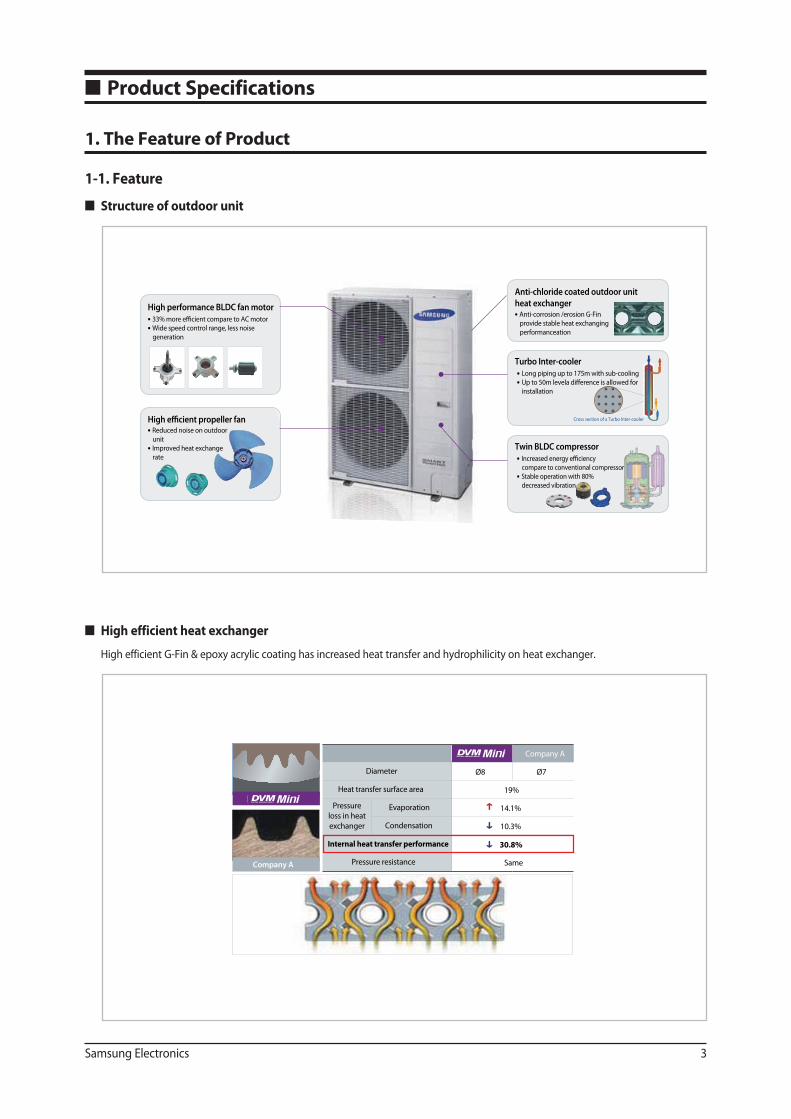
High performance BLDC fan motor
Cross section of a Turbo Inter-cooler
33% more efficient compare to AC motor
Wide speed control range, less noise
generation
Turbo Inter-coolerLong piping up to 175m with sub-cooling
Up to 50m levela difference is allowed for
installation
Twin BLDC compressorIncreased energy efficiency
compare to conventional compressor
Stable operation with 80%
decreased vibration
Anti-chloride coated outdoor unit
heat exchangerAnti-corrosion /erosion G-Fin
provide stable heat exchanging
performanceation
High efficient propeller fanReduced noise on outdoor
unit
Improved heat exchange
rate
Company A
Company A
Diameter Ø8 Ø7
Heat transfer surface area 19%
Evaporation 14.1%
Condensation 10.3%
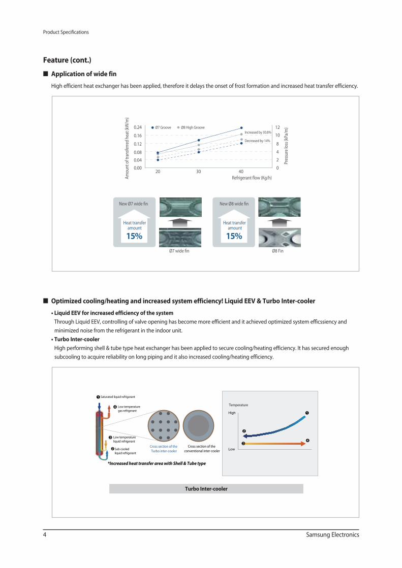
Internal heat transfer performance 30.8%
Pressure resistance Same
Pressure
loss in heat
exchanger
■ Product Specifications
1. The Feature of Product
1-1. Feature
High efficient heat exchanger
High efficient G-Fin & epoxy acrylic coating has increased heat transfer and hydrophilicity on heat exchanger.
Structure of outdoor unit
Product Specifications
4 Samsung Electronics
20 30 400
2
4
8
10
12
0.00
0.08
0.04
0.12
0.24
0.16
Am
ount
of t
rans
ferr
ed h
eat (
kW/m
)
Refrigerant flow (Kg/h)
Increased by 30.8%
Decreased by 14%
Pres
sure
loss
(kPa
/m)Ø7 Groove Ø8 High Groove
New Ø7 wide fin
Ø7 wide fin
Heat transfer amount
15%
New Ø8 wide fin
Ø8 Fin
Heat transfer amount
15%
Feature (cont.)
Optimized cooling/heating and increased system efficiency! Liquid EEV & Turbo Inter-cooler
Through Liquid EEV, controlling of valve opening has become more efficient and it achieved optimized system efficssiency and
minimized noise from the refrigerant in the indoor unit.
High performing shell & tube type heat exchanger has been applied to secure cooling/heating efficiency. It has secured enough
subcooling to acquire reliability on long piping and it also increased cooling/heating efficiency.
Application of wide fin
High efficient heat exchanger has been applied, therefore it delays the onset of frost formation and increased heat transfer efficiency.
Sub-cooled
liquid refrigerant
Low temperature
gas refrigerant
Low temperature
liquid refrigerant
Saturated liquid refrigerant
Cross section of the
Turbo inter-cooler
Cross section of the
conventional inter-cooler
*Increased heat transfer area with Shell & Tube type
온도
Temperature
Turbo Inter-cooler
Product Specifications
Samsung Electronics 5
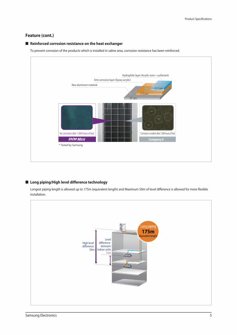
Raw aluminum material
Anti corrosive layer (Epoxy acrylic)
Hydrophilic layer (Acrylic resin + surfactant)
Company A
No corrosion after 1,000 hours of test Corrosion is evident after 1,000 hours of test
92 9m2.0 9m
0.3 9m
* Tested by Samsung
Company A
Leveldifference
betweenindoor units
15m
High level difference
50m
Long piping
175m(Equivalent length)
Feature (cont.)
Reinforced corrosion resistance on the heat exchanger
To prevent corrosion of the products which is installed in saline area, corrosion resistance has been reinforced.
Long piping/High level difference technology
Longest piping length is allowed up to 175m (equivalent length) and Maximum 50m of level difference is allowed for more flexible
installation.
Product Specifications
6 Samsung Electronics
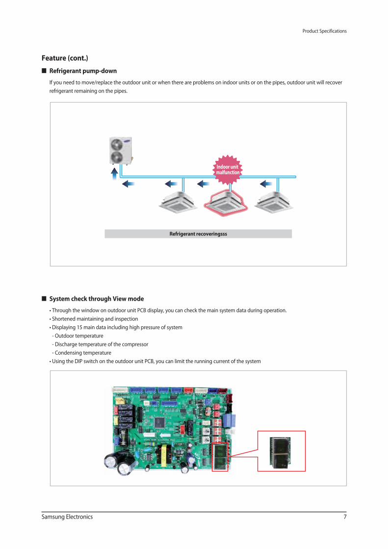
Operation time
12 hours of silent mode6 hours
7 : 00 13 : 30 19 : 00 7 : 00
End
Highest temperature
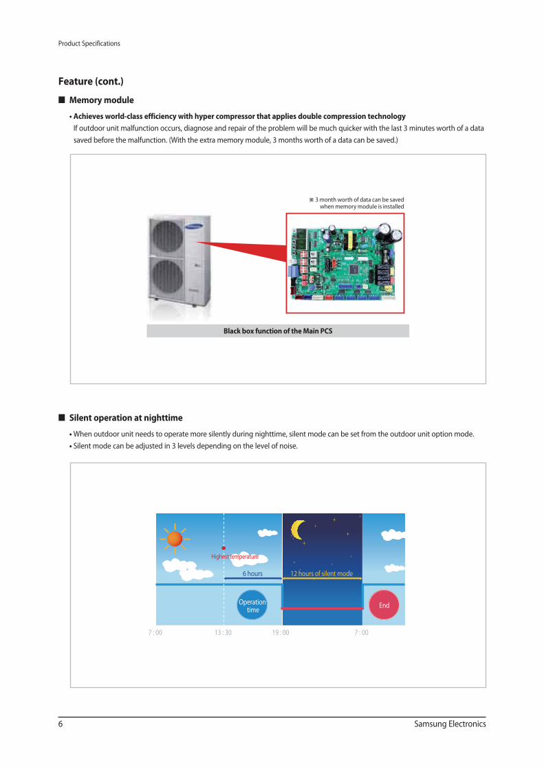
※ 3 month worth of data can be saved when memory module is installed
Black box function of the Main PCS
Feature (cont.)
Memory module
If outdoor unit malfunction occurs, diagnose and repair of the problem will be much quicker with the last 3 minutes worth of a data
saved before the malfunction. (With the extra memory module, 3 months worth of a data can be saved.)
Silent operation at nighttime
When outdoor unit needs to operate more silently during nighttime, silent mode can be set from the outdoor unit option mode.
Silent mode can be adjusted in 3 levels depending on the level of noise.
Product Specifications
Samsung Electronics 7
Refrigerant pump-down
If you need to move/replace the outdoor unit or when there are problems on indoor units or on the pipes, outdoor unit will recover
refrigerant remaining on the pipes.
Indoor unit malfunction
Refrigerant recoveringsss
Feature (cont.)
System check through View mode
Through the window on outdoor unit PCB display, you can check the main system data during operation.
Shortened maintaining and inspection
Displaying 15 main data including high pressure of system
- Outdoor temperature
- Discharge temperature of the compressor
- Condensing temperature
Using the DIP switch on the outdoor unit PCB, you can limit the running current of the system
Product Specifications
8 Samsung Electronics
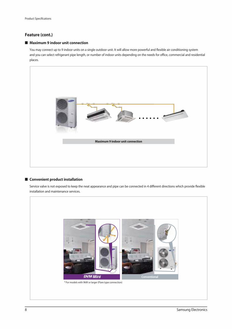
Feature (cont.)
Conventional
* For models with 9kW or larger (Flare type connection)
Convenient product installation
Service valve is not exposed to keep the neat appearance and pipe can be connected in 4 different directions which provide flexible
installation and maintenance services.
Maximum 9 indoor unit connection
Maximum 9 indoor unit connection
You may connect up to 9 indoor units on a single outdoor unit. It will allow more powerful and flexible air conditioning system
and you can select refrigerant pipe length, or number of indoor units depending on the needs for office, commercial and residential
places.
Samsung Electronics 9
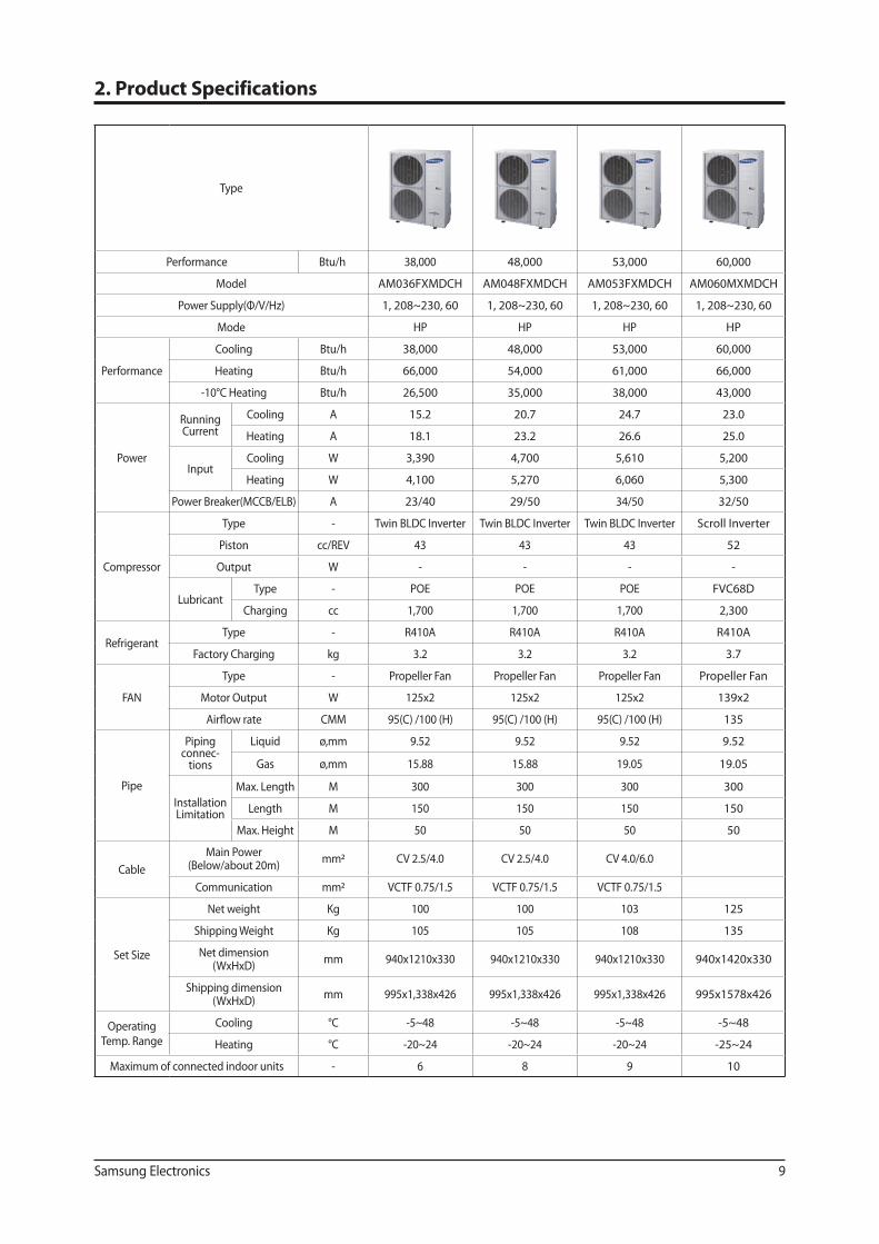
Type
Performance Btu/h 38,000 48,000 53,000 60,000
Model AM036FXMDCH AM048FXMDCH AM053FXMDCH AM060MXMDCH
Power Supply(Φ/V/Hz) 1, 208~230, 60 1, 208~230, 60 1, 208~230, 60 1, 208~230, 60
Mode HP HP HP HP
Performance
Cooling Btu/h 38,000 48,000 53,000 60,000
Heating Btu/h 66,000 54,000 61,000 66,000
-10°C Heating Btu/h 26,500 35,000 38,000 43,000
Power
Running Current
Cooling A 15.2 20.7 24.7 23.0
Heating A 18.1 23.2 26.6 25.0
InputCooling W 3,390 4,700 5,610 5,200
Heating W 4,100 5,270 6,060 5,300
Power Breaker(MCCB/ELB) A 23/40 29/50 34/50 32/50
Compressor
Type - Twin BLDC Inverter Twin BLDC Inverter Twin BLDC Inverter Scroll Inverter
Piston cc/REV 43 43 43 52
Output W - - - -
LubricantType - POE POE POE FVC68D
Charging cc 1,700 1,700 1,700 2,300
RefrigerantType - R410A R410A R410A R410A
Factory Charging kg 3.2 3.2 3.2 3.7
FAN
Type - Propeller Fan Propeller Fan Propeller Fan Propeller Fan
Motor Output W 125x2 125x2 125x2 139x2
Airflow rate CMM 95(C) /100 (H) 95(C) /100 (H) 95(C) /100 (H) 135
Pipe
Piping connec-
tions
Liquid ø,mm 9.52 9.52 9.52 9.52
Gas ø,mm 15.88 15.88 19.05 19.05
Installation Limitation
Max. Length M 300 300 300 300
Length M 150 150 150 150
Max. Height M 50 50 50 50
Cable
Main Power(Below/about 20m)
mm2 CV 2.5/4.0 CV 2.5/4.0 CV 4.0/6.0
Communication mm2 VCTF 0.75/1.5 VCTF 0.75/1.5 VCTF 0.75/1.5
Set Size
Net weight Kg 100 100 103 125
Shipping Weight Kg 105 105 108 135
Net dimension(WxHxD)
mm 940x1210x330 940x1210x330 940x1210x330 940x1420x330
Shipping dimension(WxHxD)
mm 995x1,338x426 995x1,338x426 995x1,338x426 995x1578x426
Operating Temp. Range
Cooling °C -5~48 -5~48 -5~48 -5~48
Heating °C -20~24 -20~24 -20~24 -25~24
Maximum of connected indoor units - 6 8 9 10
2. Product Specifications
10 Samsung Electronics
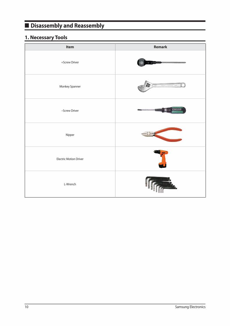
1. Necessary Tools
■ Disassembly and Reassembly
Item Remark
+Screw Driver
Monkey Spanner
–Screw Driver
Nipper
Electric Motion Driver
L-Wrench
Samsung Electronics 11
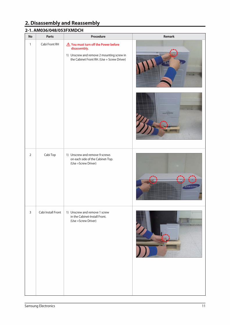
No Parts Procedure Remark
1 Cabi Front RH You must turn off the Power before disassembly.
1) Unscrew and remove 2 mounting screw in
the Cabinet Front RH. (Use + Screw Driver)
2 Cabi Top 1) Unscrew and remove 9 screws
on each side of the Cabinet-Top.
(Use +Screw Driver)
3 Cabi Install Front 1) Unscrew and remove 1 screw
in the Cabinet-Install Front.
(Use +Screw Driver)
2. Disassembly and Reassembly
2-1. AM036/048/053FXMDCH
12 Samsung Electronics
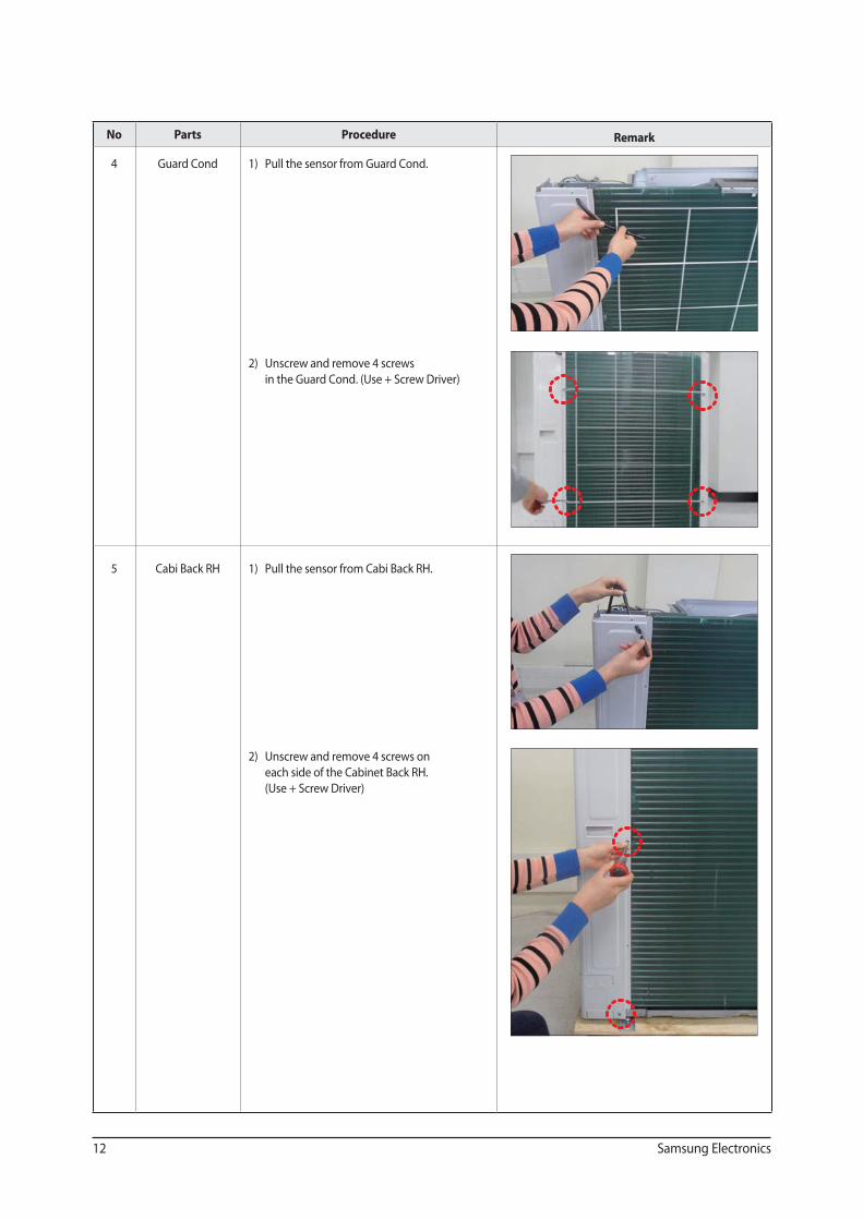
No Parts Procedure Remark
4 Guard Cond 1) Pull the sensor from Guard Cond.
2) Unscrew and remove 4 screws
in the Guard Cond. (Use + Screw Driver)
5 Cabi Back RH 1) Pull the sensor from Cabi Back RH.
2) Unscrew and remove 4 screws on
each side of the Cabinet Back RH.
(Use + Screw Driver)
Samsung Electronics 13
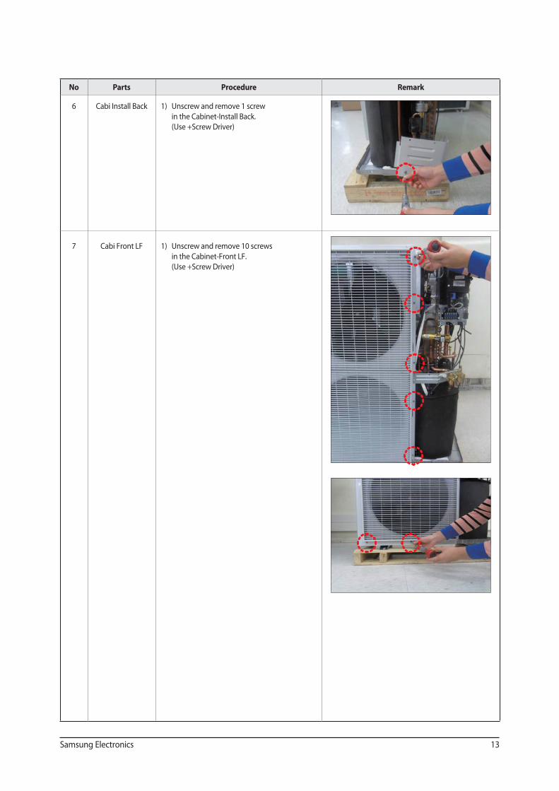
No Parts Procedure Remark
6 Cabi Install Back 1) Unscrew and remove 1 screw
in the Cabinet-Install Back.
(Use +Screw Driver)
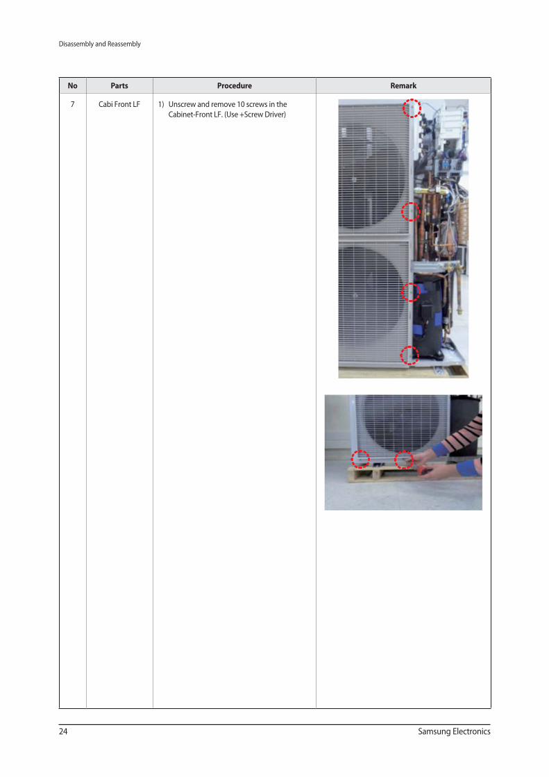
7 Cabi Front LF 1) Unscrew and remove 10 screws
in the Cabinet-Front LF.
(Use +Screw Driver)
14 Samsung Electronics
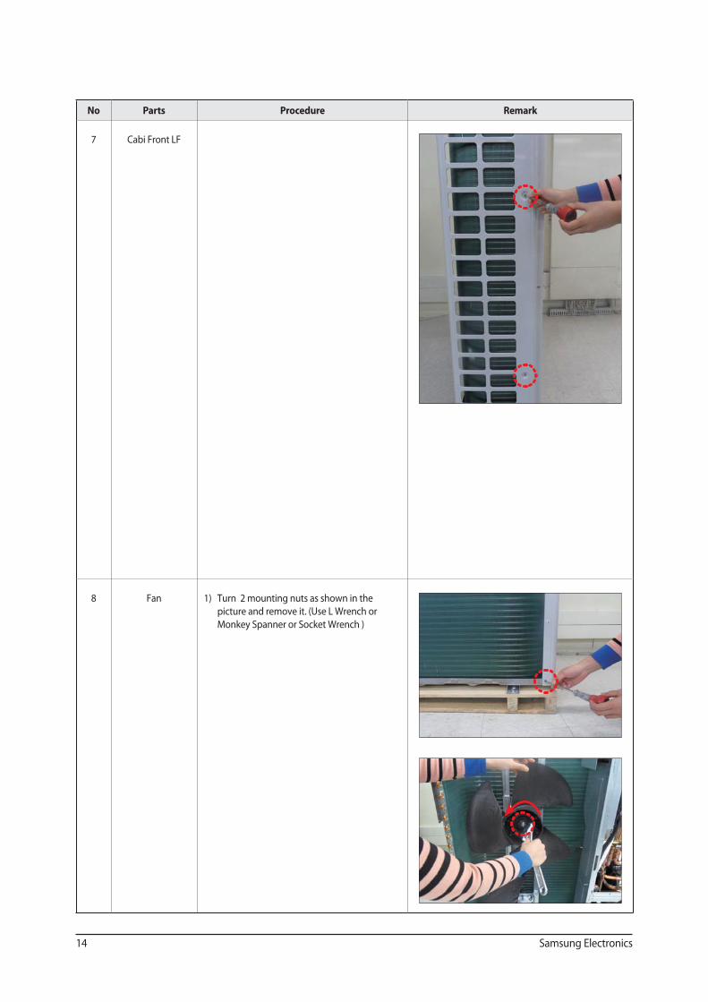
No Parts Procedure Remark
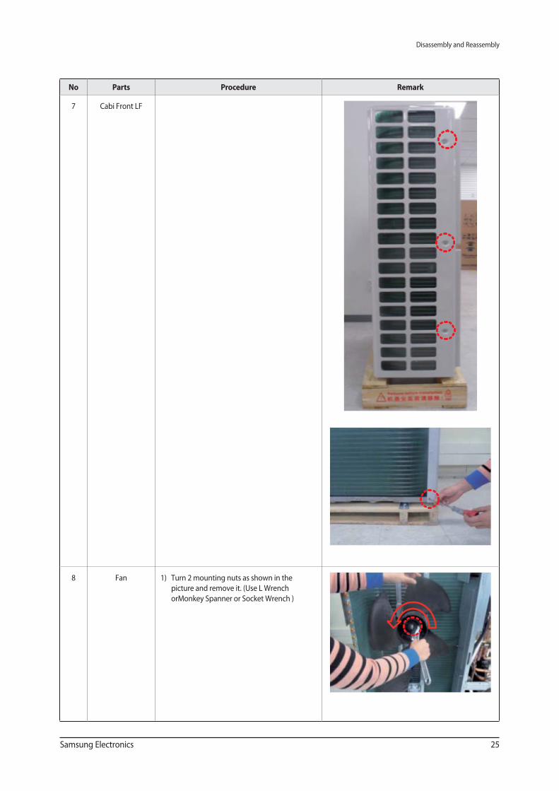
7 Cabi Front LF
8 Fan 1) Turn 2 mounting nuts as shown in the
picture and remove it. (Use L Wrench or
Monkey Spanner or Socket Wrench )
Samsung Electronics 15
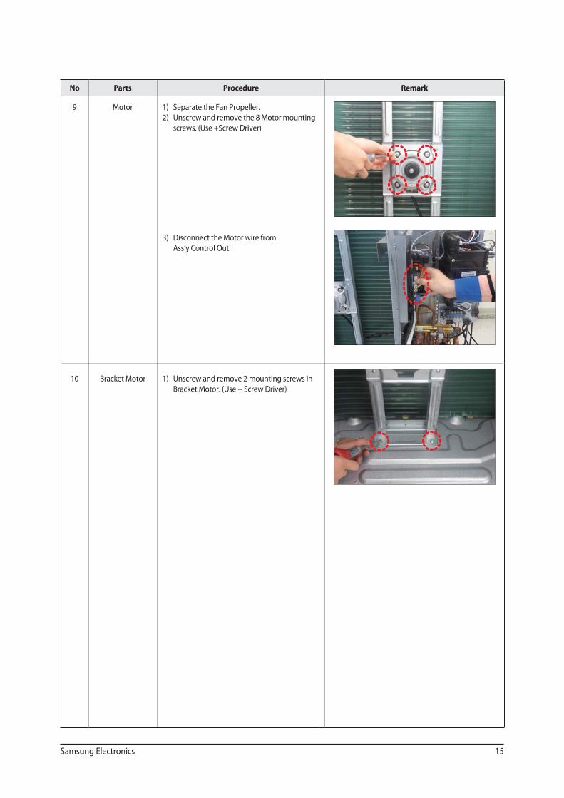
No Parts Procedure Remark
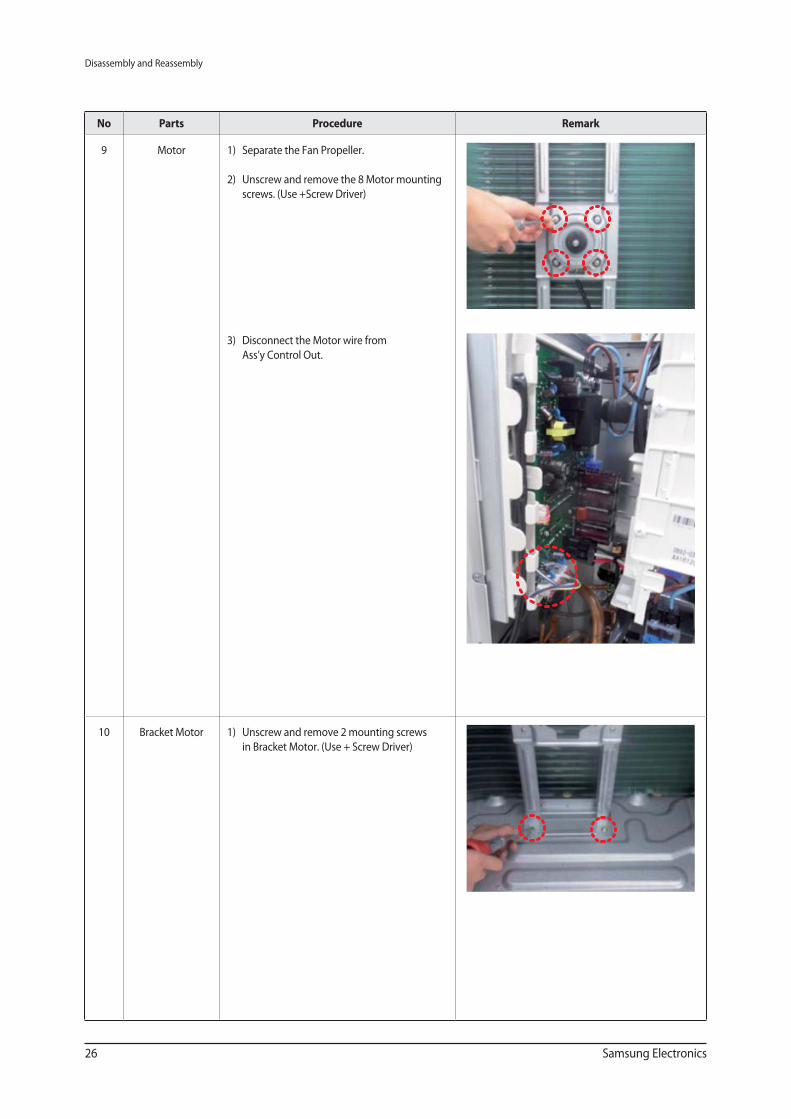
9 Motor 1) Separate the Fan Propeller.
2) Unscrew and remove the 8 Motor mounting
screws. (Use +Screw Driver)
3) Disconnect the Motor wire from
Ass’y Control Out.
10 Bracket Motor 1) Unscrew and remove 2 mounting screws in
Bracket Motor. (Use + Screw Driver)
16 Samsung Electronics
No Parts Procedure Remark
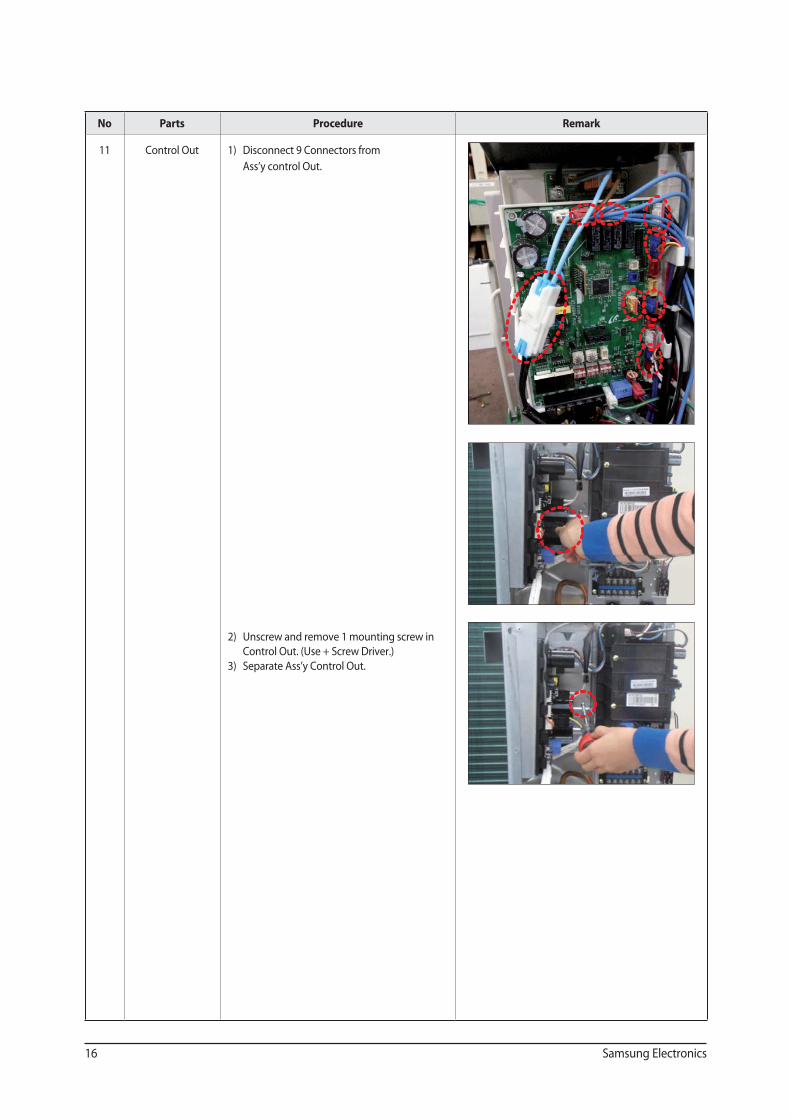
11 Control Out 1) Disconnect 9 Connectors from
Ass’y control Out.
2) Unscrew and remove 1 mounting screw in
Control Out. (Use + Screw Driver.)
3) Separate Ass’y Control Out.
Samsung Electronics 17
No Parts Procedure Remark
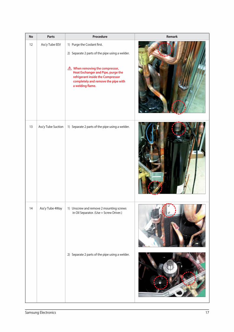
12 Ass'y Tube EEV 1) Purge the Coolant first.
2) Separate 2 parts of the pipe using a welder.
When removing the compressor, Heat Exchanger and Pipe, purge the
refrigerant inside the Compressor
completely and remove the pipe with
a welding flame.
13 Ass'y Tube Suction 1) Separate 2 parts of the pipe using a welder.
14 Ass'y Tube 4Way 1) Unscrew and remove 2 mounting screws
in Oil Separator. (Use + Screw Driver.)
2) Separate 2 parts of the pipe using a welder.
18 Samsung Electronics
No Parts Procedure Remark
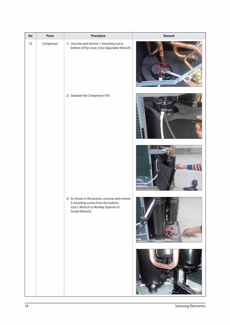
13 Compressor 1) Unscrew and remove 1 mounting nut in
bottom of the cover. (Use Adjustable Wrench)
2) Separate the Compressor Felt.
3) As shown in the picture, unscrew and remove
3 mounting screws from the bottom.
(Use L-Wrench or Monkey Spanner or
Socket Wrench)
Samsung Electronics 19
No Parts Procedure Remark
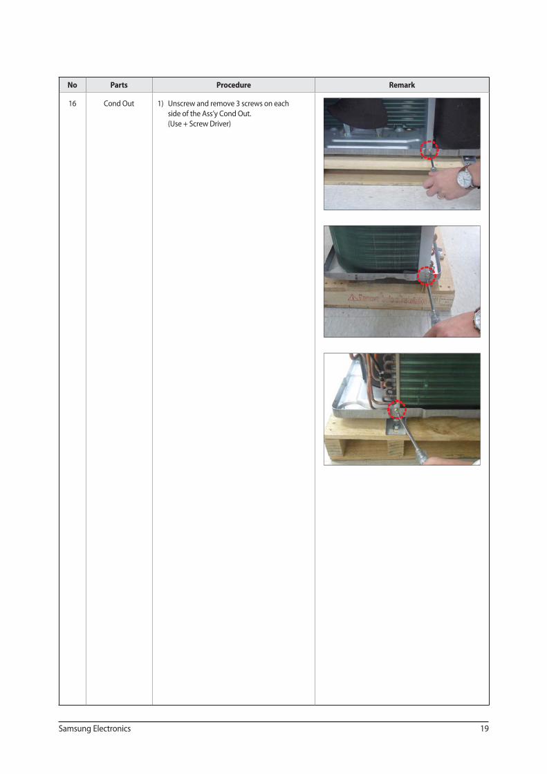
16 Cond Out 1) Unscrew and remove 3 screws on each
side of the Ass’y Cond Out.
(Use + Screw Driver)
Disassembly and Reassembly
20 Samsung Electronics
No Parts Procedure Remark
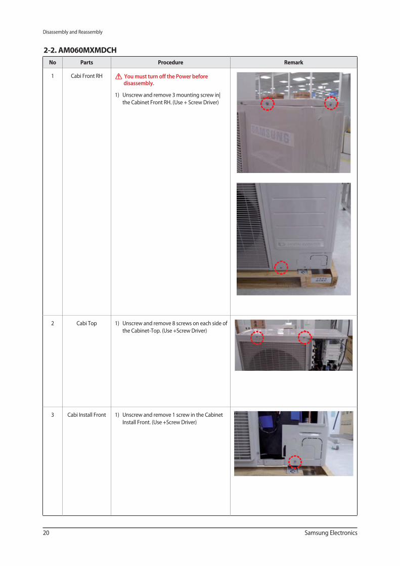
1 Cabi Front RH You must turn off the Power before disassembly.
1) Unscrew and remove 3 mounting screw in|
the Cabinet Front RH. (Use + Screw Driver)
2 Cabi Top 1) Unscrew and remove 8 screws on each side of
the Cabinet-Top. (Use +Screw Driver)
3 Cabi Install Front 1) Unscrew and remove 1 screw in the Cabinet
Install Front. (Use +Screw Driver)
2-2. AM060MXMDCH
Disassembly and Reassembly
Samsung Electronics 21
No Parts Procedure Remark
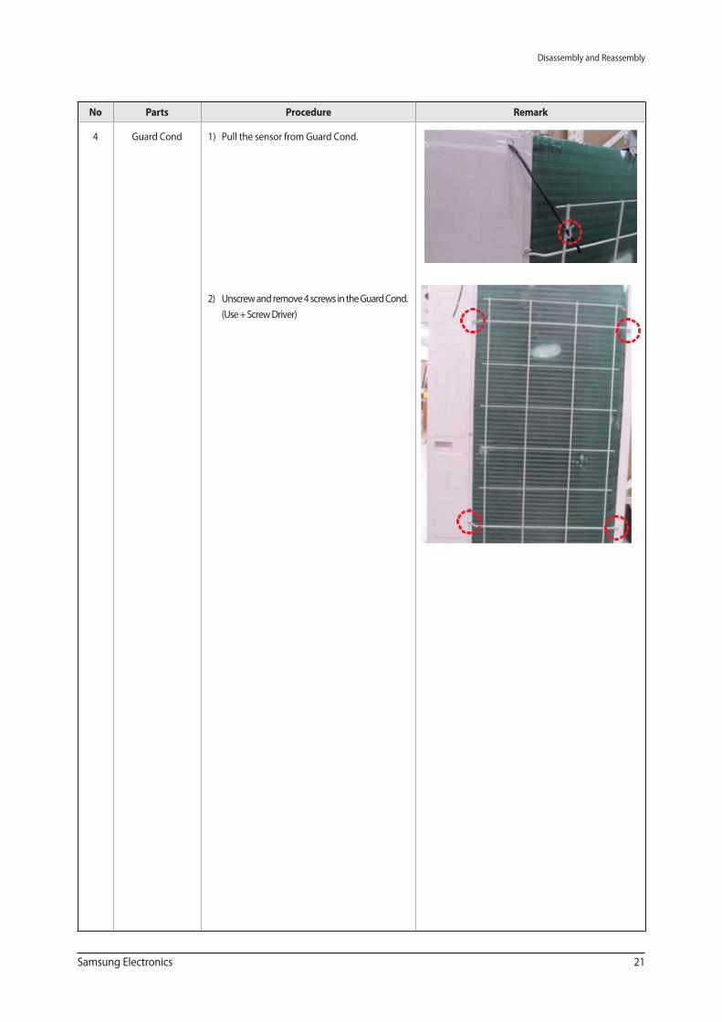
4 Guard Cond 1) Pull the sensor from Guard Cond.
2) Unscrew and remove 4 screws in the Guard Cond.
(Use + Screw Driver)
Disassembly and Reassembly
22 Samsung Electronics
No Parts Procedure Remark
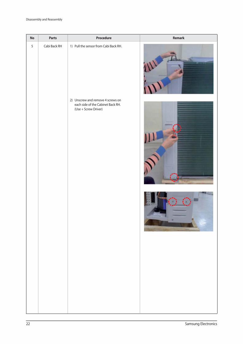
5 Cabi Back RH 1) Pull the sensor from Cabi Back RH.
2) Unscrew and remove 4 screws on
each side of the Cabinet Back RH.
(Use + Screw Driver)
Disassembly and Reassembly
Samsung Electronics 23
No Parts Procedure Remark
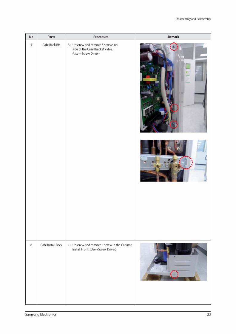
5 Cabi Back RH 3) Unscrew and remove 5 screws on
side of the Case Bracket valve.
(Use + Screw Driver)
6 Cabi Install Back 1) Unscrew and remove 1 screw in the Cabinet
Install Front. (Use +Screw Driver)
Disassembly and Reassembly
24 Samsung Electronics
No Parts Procedure Remark
7 Cabi Front LF 1) Unscrew and remove 10 screws in the
Cabinet-Front LF. (Use +Screw Driver)
Disassembly and Reassembly
Samsung Electronics 25
No Parts Procedure Remark
7 Cabi Front LF
8 Fan 1) Turn 2 mounting nuts as shown in the
picture and remove it. (Use L Wrench
orMonkey Spanner or Socket Wrench )
Disassembly and Reassembly
26 Samsung Electronics
No Parts Procedure Remark
9 Motor 1) Separate the Fan Propeller.
2) Unscrew and remove the 8 Motor mounting
screws. (Use +Screw Driver)
3) Disconnect the Motor wire from
Ass’y Control Out.
10 Bracket Motor 1) Unscrew and remove 2 mounting screws
in Bracket Motor. (Use + Screw Driver)
Disassembly and Reassembly
Samsung Electronics 27
No Parts Procedure Remark
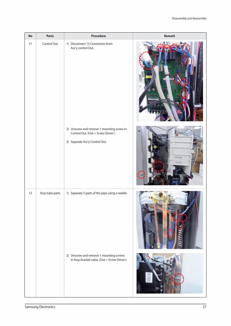
11 Control Out 1) Disconnect 13 Connectors from
Ass’y control Out.
2) Unscrew and remove 1 mounting screw in
Control Out. (Use + Screw Driver.)
3) Separate Ass’y Control Out.
12 Assy tube parts 1) Separate 5 parts of the pipe using a welder.
2) Unscrew and remove 1 mounting screws
in Assy bracket valve. (Use + Screw Driver.)
Disassembly and Reassembly
28 Samsung Electronics
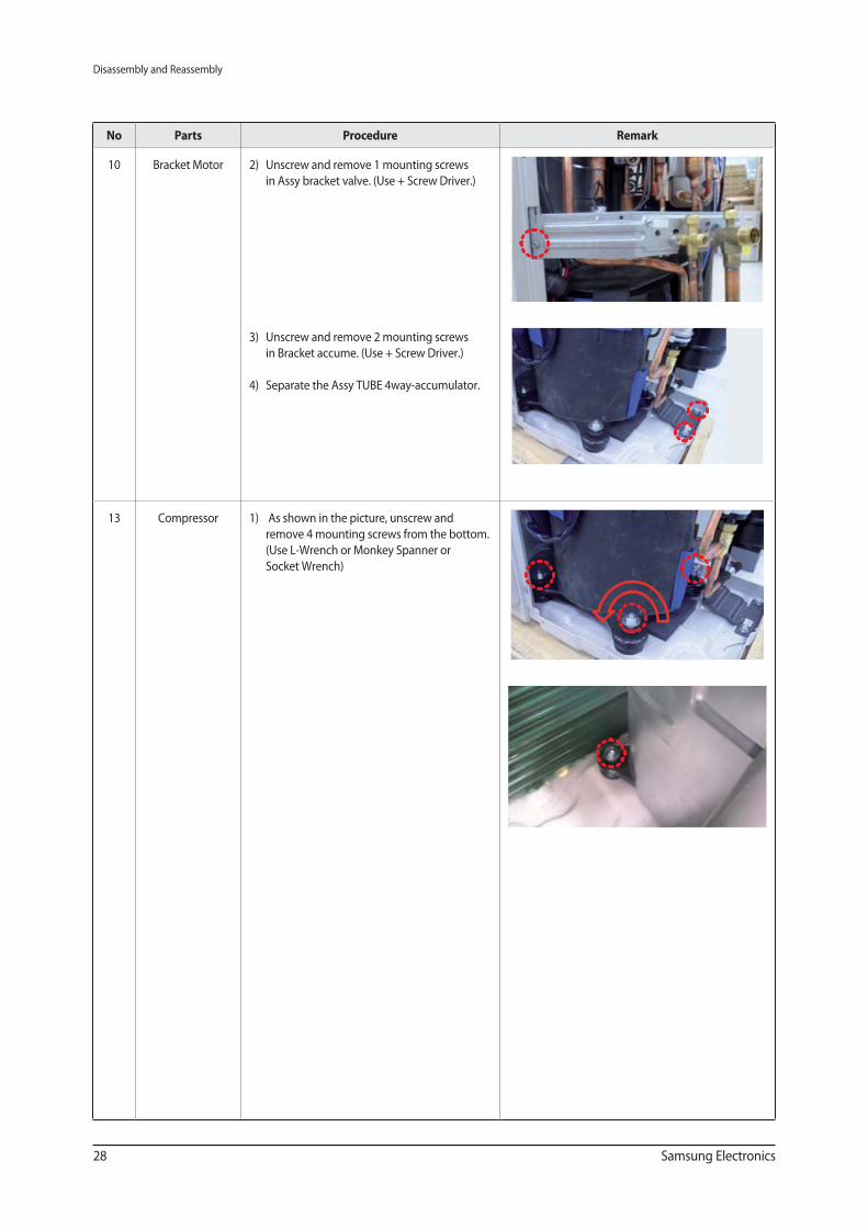
No Parts Procedure Remark
10 Bracket Motor 2) Unscrew and remove 1 mounting screws
in Assy bracket valve. (Use + Screw Driver.)
3) Unscrew and remove 2 mounting screws
in Bracket accume. (Use + Screw Driver.)
4) Separate the Assy TUBE 4way-accumulator.
13 Compressor 1) As shown in the picture, unscrew and
remove 4 mounting screws from the bottom.
(Use L-Wrench or Monkey Spanner or
Socket Wrench)
Disassembly and Reassembly
Samsung Electronics 29
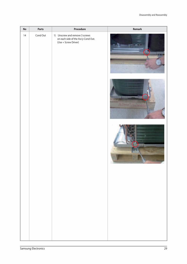
No Parts Procedure Remark
14 Cond Out 1) Unscrew and remove 3 screws
on each side of the Ass’y Cond Out.
(Use + Screw Driver)
30 Samsung Electronics
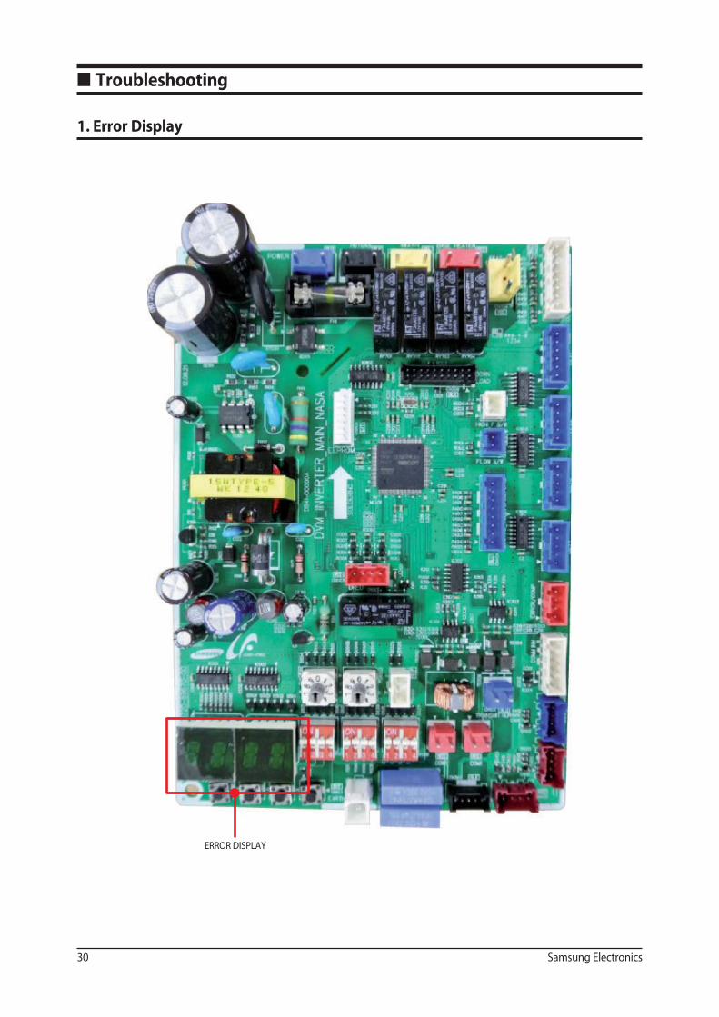
ERROR DISPLAY
■ Troubleshooting
1. Error Display
Samsung Electronics 31
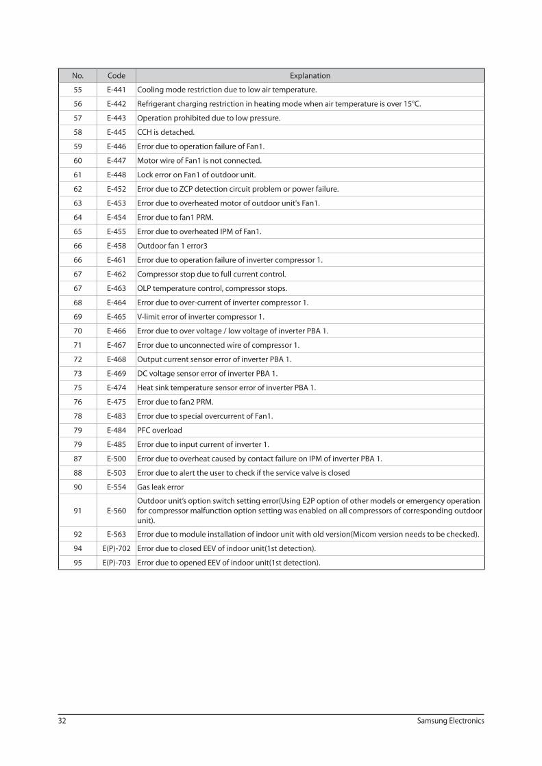
2. Error Code
No. Code Explanation
1 E-108 Error due to repeated address setting(when 2 or more devices has same address within the network).
2 E-121 Error on indoor temperature sensor of indoor unit(Short or Open).
3 E-122 Error on EVA IN sensor of indoor unit(Short or Open).
4 E-123 Error on EVA OUT sensor of indoor unit(Short or Open).
5 E-128 EVA IN temperature sensor of indoor unit is detached from EVA IN pipe.
6 E-129 EVA OUT temperature sensor of indoor unit is detached from EVA OUT pipe.
7 E-149 Error due to AHU MASTER indoor unit sensor setting.
8 E-151 Error due to opened EEV of indoor unit(2nd detection).
9 E-152 Error due to closed EEV of indoor unit(2nd detection).
10 E-153 Error on oat switch of indoor unit(2nd detection).
11 E-154 RPM feedback error of indoor unit.
12 E-162 EEPROM error of MICOM(Physical problem of parts/circuit).
13 E-163 Indoor unit’s remote controller option input is incorrect or missing, Outdoor unit EEPROM data error.
14 E-198 Error due to disconnected thermal fuse of indoor unit (Temperature increase of the terminal block).
15 E-201Communication error between indoor and outdoor unit (Installation number setting error repeated
indoor unit address, indoor unit communication cable error).
16 E-202Communication error between indoor and outdoor unit(Communication error on all indoor unit,
outdoor unit communication cable error).
17 E-203Communication error between main and sub micom or communication error
betten main and sub outdoor units.
17 E-205 Communication error on all PBA within the outdoor unit C-Box, communication cable error.
19 E-221 Error on outdoor temperature sensor of outdoor unit (Short or open).
20 E-231 Error on COND OUT temperature sensor of main outdoor unit (Short or open).
21 E-241 COND OUT sensor in detached.
22 E-251 Error on discharge temperature sensor of compressor 1 (Short or open).
23 E-262 Discharge temperature sensor of compressor 1 is detached from the sensor holder on the pipe.
24 E-266 Top sensor of compressor 1 is detached.
25 E-269 Suction temperature sensor is detached from the sensor holder on the pipe.
26 E-276 Error on Top sensor of compressor 1(Short or open).
27 E-291 Refrigerant leakage or error on high pressure sensor(Short or open).
28 E-296 Refrigerant leakage or error on low pressure sensor(Short or open).
29 E-308 Error on suction temperature sensor(Short or open).
30 E-311 Error on temperature sensor of double layer pipe/liquid pipe(sub heat exchanger)(Short or open).
31 E-321 Error on EVI(ESC) IN temperature sensor(Short or open).
32 E-322 Error on EVI(ESC) OUT temperature sensor(Short or open).
47 E-407 Compressor operation stop due to high pressure protection control.
48 E-410 Compressor operation stop due to low pressure protection control or refrigerant leakage.
49 E-416 Compressor operation stop due to discharge temperature protection control.
50 E-425 Phase reversal or phase failure(3Ø outdoor unit wiring, R-S-T-N),connection error on 3 phase input.
51 E-428 Compressor operation stop due to abnormal compression ratio.
52 E-438EVI(ESC) EEV leakage or internal leakage of intercooler or incorrect connector insertion of EVI(ESC)
EEV.
53 E-439 Error due to refrigerant leakage.
54 E-440 Heating mode restriction due to high air temperature.
32 Samsung Electronics
No. Code Explanation
55 E-441 Cooling mode restriction due to low air temperature.
56 E-442 Refrigerant charging restriction in heating mode when air temperature is over 15°C.
57 E-443 Operation prohibited due to low pressure.
58 E-445 CCH is detached.
59 E-446 Error due to operation failure of Fan1.
60 E-447 Motor wire of Fan1 is not connected.
61 E-448 Lock error on Fan1 of outdoor unit.
62 E-452 Error due to ZCP detection circuit problem or power failure.
63 E-453 Error due to overheated motor of outdoor unit's Fan1.
64 E-454 Error due to fan1 PRM.
65 E-455 Error due to overheated IPM of Fan1.
66 E-458 Outdoor fan 1 error3
66 E-461 Error due to operation failure of inverter compressor 1.
67 E-462 Compressor stop due to full current control.
67 E-463 OLP temperature control, compressor stops.
68 E-464 Error due to over-current of inverter compressor 1.
69 E-465 V-limit error of inverter compressor 1.
70 E-466 Error due to over voltage / low voltage of inverter PBA 1.
71 E-467 Error due to unconnected wire of compressor 1.
72 E-468 Output current sensor error of inverter PBA 1.
73 E-469 DC voltage sensor error of inverter PBA 1.
75 E-474 Heat sink temperature sensor error of inverter PBA 1.
76 E-475 Error due to fan2 PRM.
78 E-483 Error due to special overcurrent of Fan1.
79 E-484 PFC overload
79 E-485 Error due to input current of inverter 1.
87 E-500 Error due to overheat caused by contact failure on IPM of inverter PBA 1.
88 E-503 Error due to alert the user to check if the service valve is closed
90 E-554 Gas leak error
91 E-560
Outdoor unit’s option switch setting error(Using E2P option of other models or emergency operation
for compressor malfunction option setting was enabled on all compressors of corresponding outdoor
unit).
92 E-563 Error due to module installation of indoor unit with old version(Micom version needs to be checked).
94 E(P)-702 Error due to closed EEV of indoor unit(1st detection).
95 E(P)-703 Error due to opened EEV of indoor unit(1st detection).
Samsung Electronics 33
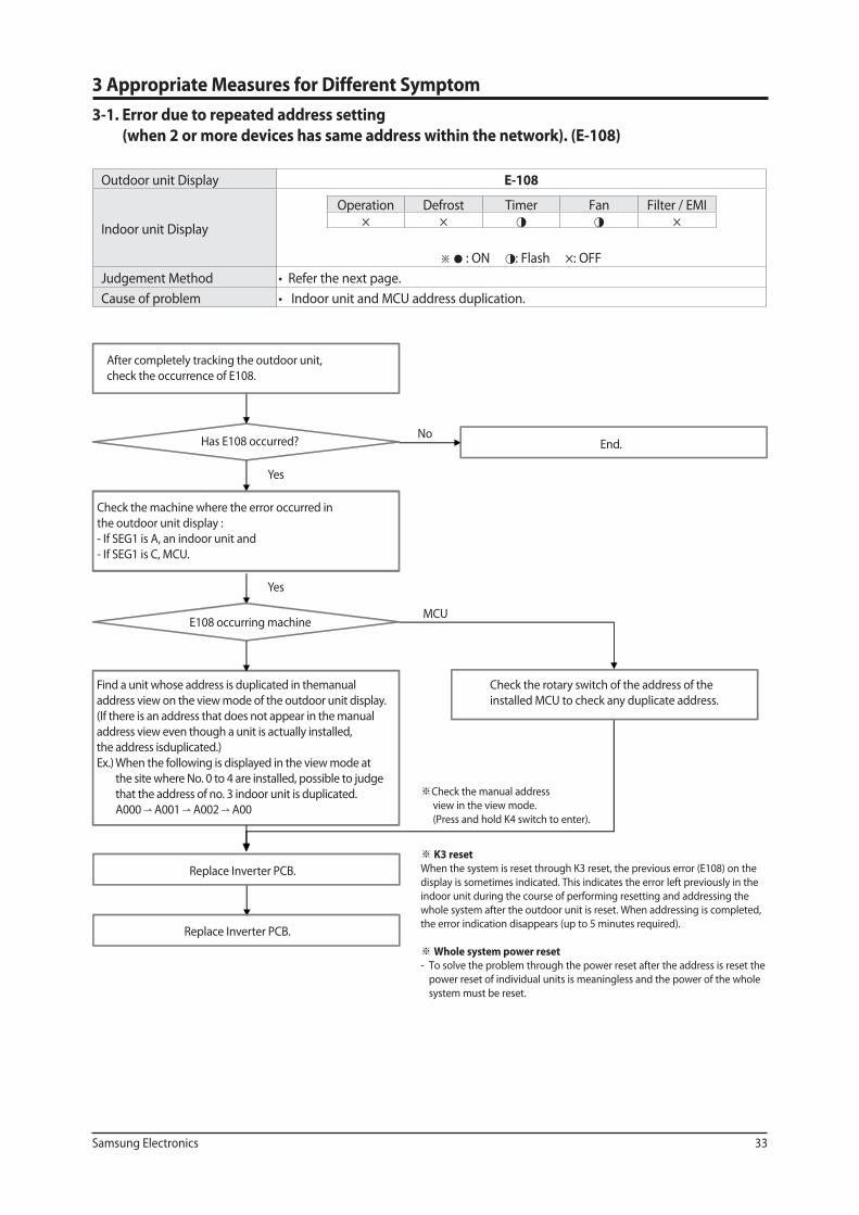
Outdoor unit Display E-108
Indoor unit Display
Operation Defrost Timer Fan Filter / EMI× × ◑ ◑ ×
※ ● : ON ◑: Flash ×: OFF
Judgement Method
Cause of problem
K3 reset
When the system is reset through K3 reset, the previous error (E108) on the
display is sometimes indicated. This indicates the error left previously in the
indoor unit during the course of performing resetting and addressing the
whole system after the outdoor unit is reset. When addressing is completed,
the error indication disappears (up to 5 minutes required).
Whole system power reset
- To solve the problem through the power reset after the address is reset the
power reset of individual units is meaningless and the power of the whole
system must be reset.
After completely tracking the outdoor unit,
check the occurrence of E108.
Has E108 occurred?
Check the machine where the error occurred in
the outdoor unit display :
- If SEG1 is A, an indoor unit and
- If SEG1 is C, MCU.
E108 occurring machine
Find a unit whose address is duplicated in themanual
address view on the view mode of the outdoor unit display.
(If there is an address that does not appear in the manual
address view even though a unit is actually installed,
the address isduplicated.)
Ex.) When the following is displayed in the view mode at
the site where No. 0 to 4 are installed, possible to judge
that the address of no. 3 indoor unit is duplicated.
A000 A001 A002 A00
Replace Inverter PCB.
Replace Inverter PCB.
End.
Check the rotary switch of the address of the
installed MCU to check any duplicate address.
Yes
Yes
No
MCU
Check the manual address
view in the view mode.
(Press and hold K4 switch to enter).
3 Appropriate Measures for Different Symptom
3-1. Error due to repeated address setting
(when 2 or more devices has same address within the network). (E-108)
34 Samsung Electronics
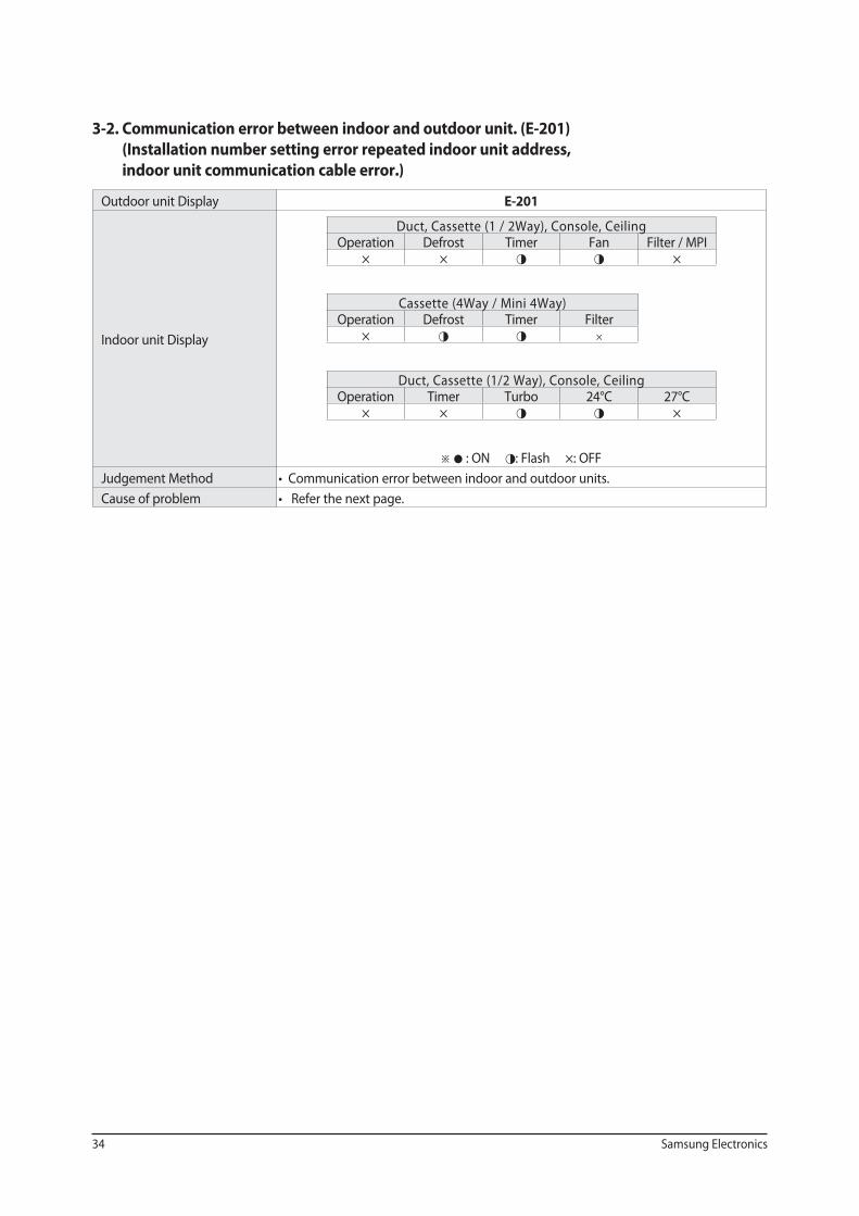
3-2. Communication error between indoor and outdoor unit. (E-201)
(Installation number setting error repeated indoor unit address,
indoor unit communication cable error.)
Outdoor unit Display E-201
Indoor unit Display
Duct, Cassette (1 / 2Way), Console, CeilingOperation Defrost Timer Fan Filter / MPI
× × ◑ ◑ ×
Cassette (4Way / Mini 4Way) Operation Defrost Timer Filter
× ◑ ◑ ×
Duct, Cassette (1/2 Way), Console, Ceiling Operation Timer Turbo 24°C 27°C
× × ◑ ◑ ×
※ ● : ON ◑: Flash ×: OFF
Judgement Method
Cause of problem
Samsung Electronics 35
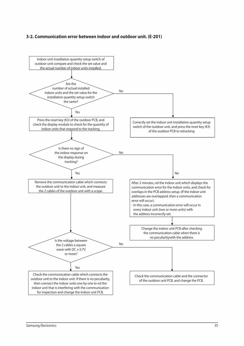
3-2. Communication error between indoor and outdoor unit. (E-201)
Indoor unit installation quantity setup switch of
outdoor unit compare and check the set value and
the actual number of indoor units installed.
Are the
number of actual installed
indoor units and the set value for the
installation quantity setup switch
the same?
Press the reset key (K3) of the outdoor PCB, and
check the display module to check for the quantity of
indoor units that respond to the tracking.
Is there no sign of
the indoor response on
the display during
tracking?
Correctly set the indoor unit installation quantity setup
switch of the outdoor unit, and press the reset key (K3)
of the outdoor PCB to retracking
Remove the communication cable which connects
the outdoor unit to the indoor unit, and measure
the 2 cables of the outdoor unit with a scope.
Is the voltage between
the 2 cables a square
wave with DC ± 0.7V
or more?
After 2 minutes, nd the indoor unit which displays the
communication error for the indoor units, and check for
overlaps in the PCB address setup. (If the indoor unit
addresses are overlapped, then a communication
error will occur).
- In this case, a communication error will occur in
every indoor unit (two or more units) with
the address incorrectly set.
Change the indoor unit PCB after checking
the communication cable when there is
no peculiaritywith the address.
Check the communication cable which connects the
outdoor unit to the indoor unit. If there is no peculiarity,
then connect the indoor units one by one to nd the
indoor unit that is interfering with the communication
for inspection and change the indoor unit PCB.
Check the communication cable and the connector
of the outdoor unit PCB, and change the PCB.
Yes
No
No
No
No
Yes
Yes
36 Samsung Electronics
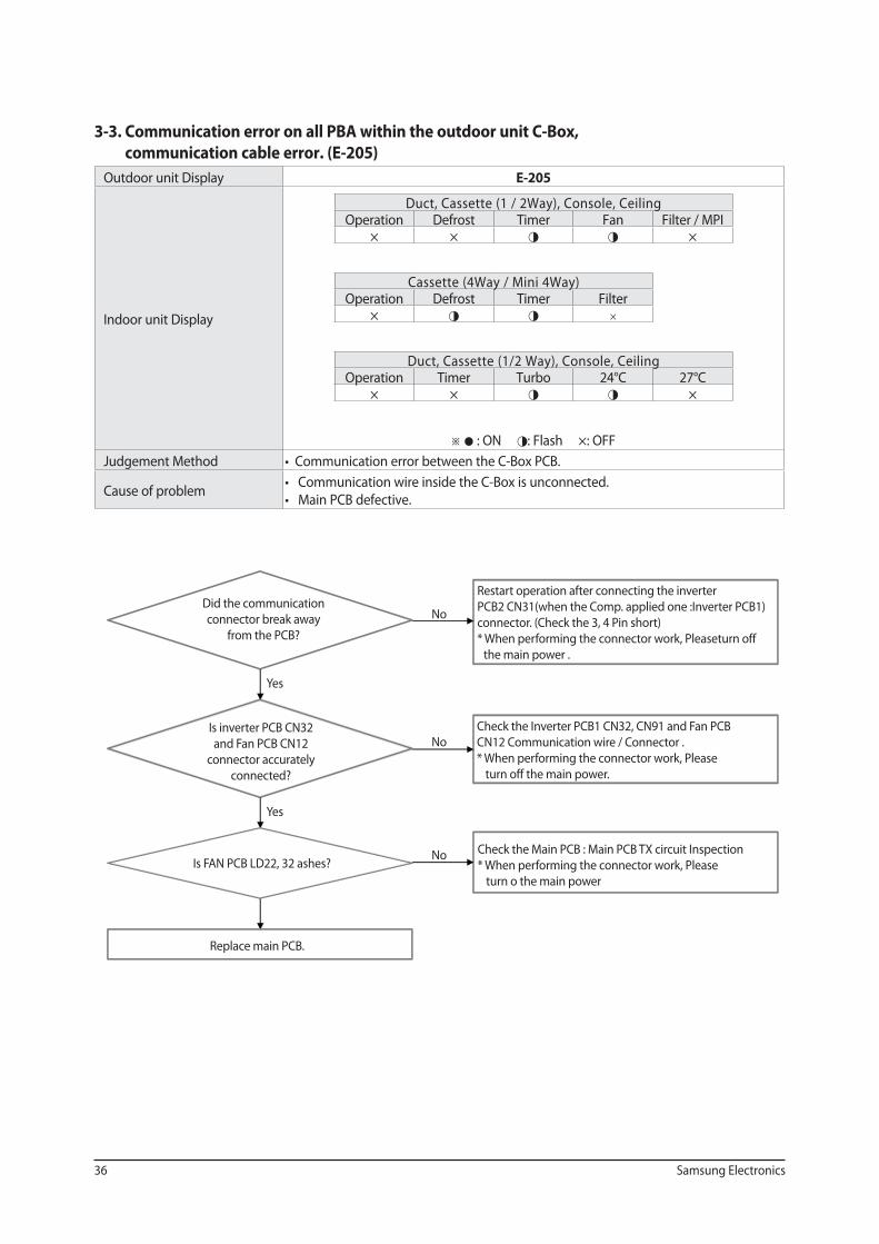
3-3. Communication error on all PBA within the outdoor unit C-Box,
communication cable error. (E-205)
Outdoor unit Display E-205
Indoor unit Display
Duct, Cassette (1 / 2Way), Console, Ceiling Operation Defrost Timer Fan Filter / MPI
× × ◑ ◑ ×
Cassette (4Way / Mini 4Way) Operation Defrost Timer Filter
× ◑ ◑ ×
Duct, Cassette (1/2 Way), Console, Ceiling Operation Timer Turbo 24°C 27°C
× × ◑ ◑ ×
※ ● : ON ◑: Flash ×: OFF
Judgement Method
Cause of problem
Did the communication
connector break away
from the PCB?
Is inverter PCB CN32
and Fan PCB CN12
connector accurately
connected?
Is FAN PCB LD22, 32 ashes?
Replace main PCB.
Restart operation after connecting the inverter
PCB2 CN31(when the Comp. applied one :Inverter PCB1)
connector. (Check the 3, 4 Pin short)
* When performing the connector work, Pleaseturn off
the main power .
Check the Inverter PCB1 CN32, CN91 and Fan PCB
CN12 Communication wire / Connector .
* When performing the connector work, Please
turn off the main power.
Check the Main PCB : Main PCB TX circuit Inspection
* When performing the connector work, Please
turn o the main power
Yes
No
Yes
No
No
Samsung Electronics 37
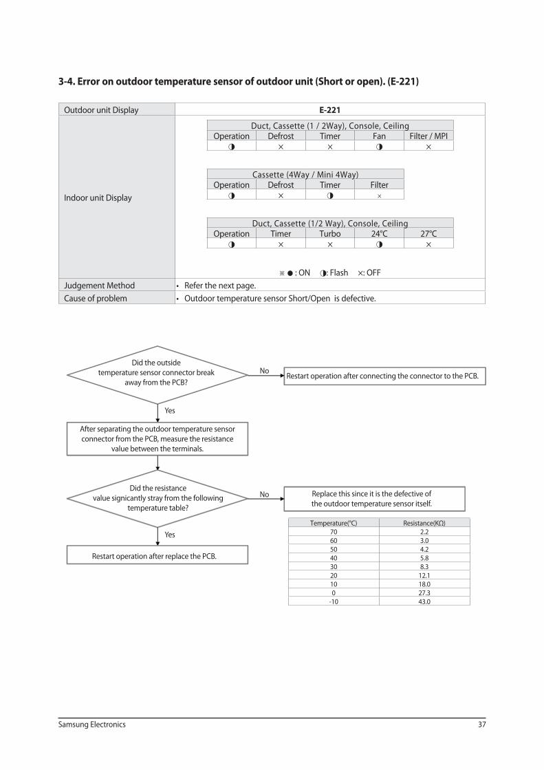
3-4. Error on outdoor temperature sensor of outdoor unit (Short or open). (E-221)
Outdoor unit Display E-221
Indoor unit Display
Duct, Cassette (1 / 2Way), Console, Ceiling Operation Defrost Timer Fan Filter / MPI◑ × × ◑ ×
Cassette (4Way / Mini 4Way) Operation Defrost Timer Filter◑ × ◑ ×
Duct, Cassette (1/2 Way), Console, Ceiling Operation Timer Turbo 24°C 27°C ◑ × × ◑ ×
※ ● : ON ◑: Flash ×: OFF
Judgement Method
Cause of problem
Temperature(°C) Resistance(KΩ)70 2.2 60 3.0 50 4.2 40 5.8 30 8.3 20 12.110 18.0 0 27.3
-10 43.0
Did the outside
temperature sensor connector break
away from the PCB?
After separating the outdoor temperature sensor
connector from the PCB, measure the resistance
value between the terminals.
Did the resistance
value signicantly stray from the following
temperature table?
Restart operation after replace the PCB.
Restart operation after connecting the connector to the PCB.
Replace this since it is the defective of
the outdoor temperature sensor itself.
Yes
Yes
No
No
38 Samsung Electronics
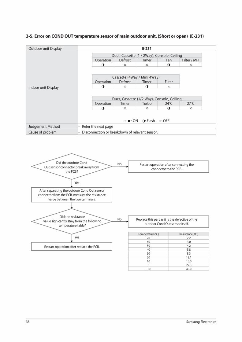
3-5. Error on COND OUT temperature sensor of main outdoor unit. (Short or open) (E-231)
Outdoor unit Display E-231
Indoor unit Display
Duct, Cassette (1 / 2Way), Console, Ceiling Operation Defrost Timer Fan Filter / MPI◑ × × ◑ ×
Cassette (4Way / Mini 4Way) Operation Defrost Timer Filter◑ × ◑ ×
Duct, Cassette (1/2 Way), Console, Ceiling Operation Timer Turbo 24°C 27°C ◑ × × ◑ ×
※ ● : ON ◑: Flash ×: OFF
Judgement Method
Cause of problem
Temperature(°C) Resistance(KΩ)70 2.2 60 3.0 50 4.2 40 5.8 30 8.3 20 12.110 18.0 0 27.3
-10 43.0
Did the outdoor Cond
Out sensor connector break away from
the PCB?
After separating the outdoor Cond Out sensor
connector from the PCB, measure the resistance
value between the two terminals.
Did the resistance
value signicantly stray from the following
temperature table?
Restart operation after replace the PCB.
Restart operation after connecting the
connector to the PCB.
Replace this part as it is the defective of the
outdoor Cond Out sensor itself.
Yes
Yes
No
No

Samsung Electronics 39
3-6. Error on discharge temperature sensor of compressor 1 (Short or open). (E-251)
Outdoor unit Display E-251
Indoor unit Display
Duct, Cassette (1 / 2Way), Console, Ceiling Operation Defrost Timer Fan Filter / MPI
× × ◑ ◑ ◑
Cassette (4Way / Mini 4Way) Operation Defrost Timer Filter
× ◑ ◑ ◑
Duct, Cassette (1/2 Way), Console, Ceiling Operation Timer Turbo 24°C 27°C
× × ◑ ◑ ◑
※ ● : ON ◑: Flash ×: OFF
Judgement Method
Cause of problem
Temperature(°C) Resistance(KΩ)130 8.9 120 11.2100 18.580 32.0 60 59.0 25 20020 24210 3620 553
Did the Compressor
Discharge or top temperature sensor
connector break away
from the PCB?
After separating the Compressor Discharge or
Top Temperature sensor connector from the PCB,
measure the resistance value between the two terminals.
Did the resistance
value signicantly stray from the following
temperature table?
Restart operation after replace the PCB.
Restart operation after connecting
the connector to PCB.
Replace this part as it is the defective of the
compressor discharge or top temperature sensor itself.
Yes
Yes
No
No
40 Samsung Electronics
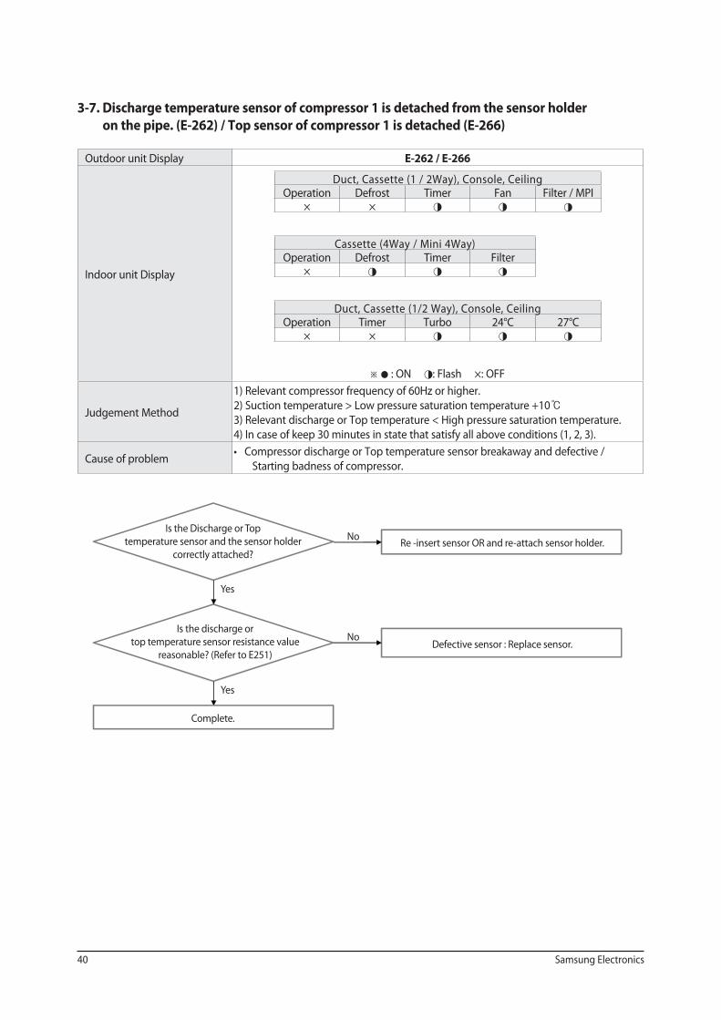
3-7. Discharge temperature sensor of compressor 1 is detached from the sensor holder
on the pipe. (E-262) / Top sensor of compressor 1 is detached (E-266)
Outdoor unit Display E-262 / E-266
Indoor unit Display
Duct, Cassette (1 / 2Way), Console, Ceiling Operation Defrost Timer Fan Filter / MPI
× × ◑ ◑ ◑
Cassette (4Way / Mini 4Way) Operation Defrost Timer Filter
× ◑ ◑ ◑
Duct, Cassette (1/2 Way), Console, Ceiling Operation Timer Turbo 24°C 27°C
× × ◑ ◑ ◑
※ ● : ON ◑: Flash ×: OFF
Judgement Method
1) Relevant compressor frequency of 60Hz or higher.
2) Suction temperature > Low pressure saturation temperature +10
3) Relevant discharge or Top temperature < High pressure saturation temperature.
4) In case of keep 30 minutes in state that satisfy all above conditions (1, 2, 3).
Cause of problem
Starting badness of compressor.
Yes
Is the Discharge or Top
temperature sensor and the sensor holder
correctly attached?
Is the discharge or
top temperature sensor resistance value
reasonable? (Refer to E251)
Complete.
Re -insert sensor OR and re-attach sensor holder.
Defective sensor : Replace sensor.
Yes
No
No
Samsung Electronics 41
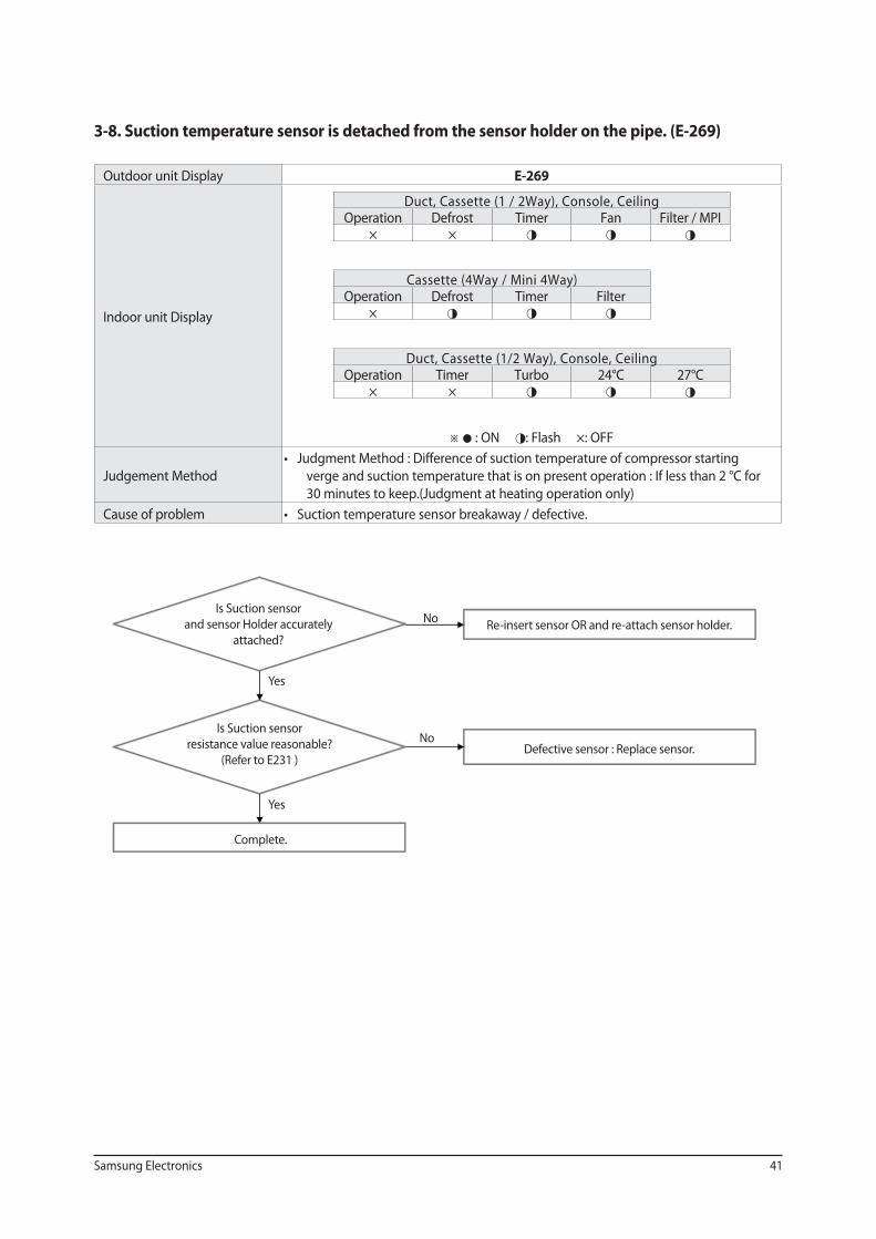
3-8. Suction temperature sensor is detached from the sensor holder on the pipe. (E-269)
Outdoor unit Display E-269
Indoor unit Display
Duct, Cassette (1 / 2Way), Console, Ceiling Operation Defrost Timer Fan Filter / MPI
× × ◑ ◑ ◑
Cassette (4Way / Mini 4Way) Operation Defrost Timer Filter
× ◑ ◑ ◑
Duct, Cassette (1/2 Way), Console, Ceiling Operation Timer Turbo 24°C 27°C
× × ◑ ◑ ◑
※ ● : ON ◑: Flash ×: OFF
Judgement Method
verge and suction temperature that is on present operation : If less than 2 °C for
30 minutes to keep.(Judgment at heating operation only)
Cause of problem
Yes
Is Suction sensor
and sensor Holder accurately
attached?
Is Suction sensor
resistance value reasonable?
(Refer to E231 )
Complete.
Re-insert sensor OR and re-attach sensor holder.
Defective sensor : Replace sensor.
Yes
No
No
42 Samsung Electronics
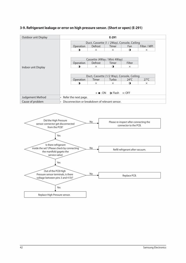
3-9. Refrigerant leakage or error on high pressure sensor. (Short or open) (E-291)
Outdoor unit Display E-291
Indoor unit Display
Duct, Cassette (1 / 2Way), Console, Ceiling Operation Defrost Timer Fan Filter / MPI◑ × × ◑ ×
Cassette (4Way / Mini 4Way) Operation Defrost Timer Filter◑ × ◑ ×
Duct, Cassette (1/2 Way), Console, Ceiling Operation Timer Turbo 24°C 27°C ◑ × × ◑ ×
※ ● : ON ◑: Flash ×: OFF
Judgement Method
Cause of problem
Did the High Pressure
sensor connector get disconnected
from the PCB?
Is there refrigerant
inside the set? (Please check by connecting
the manifold gageto the
service valve)
Out of the PCB High
Pressure sensor terminals, is there
voltage between pins 3 and 4 5V?
Replace High Pressure sensor.
Please re-inspect after connecting the
connector to the PCB.
Refill refrigerant after vacuum.
Replace PCB.
Yes
Yes
No
No
No
Yes
Samsung Electronics 43
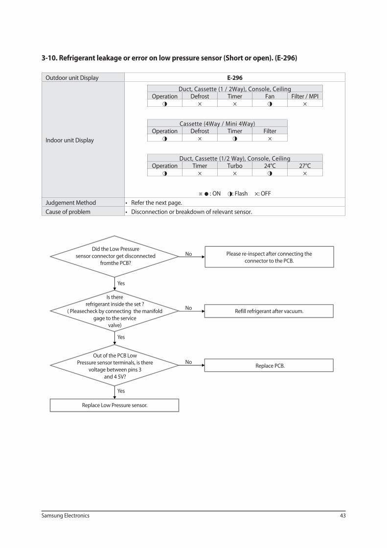
3-10. Refrigerant leakage or error on low pressure sensor (Short or open). (E-296)
Outdoor unit Display E-296
Indoor unit Display
Duct, Cassette (1 / 2Way), Console, Ceiling Operation Defrost Timer Fan Filter / MPI◑ × × ◑ ×
Cassette (4Way / Mini 4Way) Operation Defrost Timer Filter◑ × ◑ ×
Duct, Cassette (1/2 Way), Console, Ceiling Operation Timer Turbo 24°C 27°C ◑ × × ◑ ×
※ ● : ON ◑: Flash ×: OFF
Judgement Method
Cause of problem
Yes
No
Yes
Yes
No
No
Did the Low Pressure
sensor connector get disconnected
fromthe PCB?
Is there
refrigerant inside the set ?
( Pleasecheck by connecting the manifold
gage to the service
valve)
Out of the PCB Low
Pressure sensor terminals, is there
voltage between pins 3
and 4 5V?
Replace Low Pressure sensor.
Please re-inspect after connecting the
connector to the PCB.
Refill refrigerant after vacuum.
Replace PCB.
44 Samsung Electronics
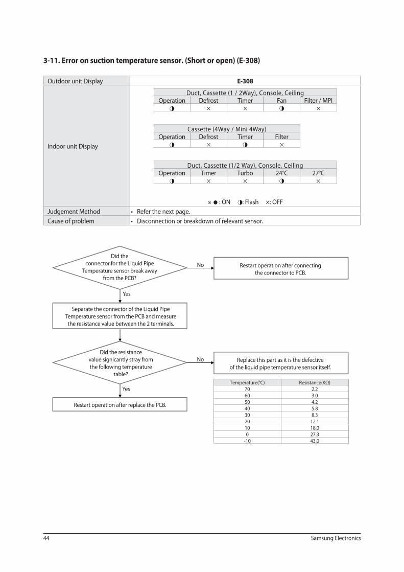
3-11. Error on suction temperature sensor. (Short or open) (E-308)
Outdoor unit Display E-308
Indoor unit Display
Duct, Cassette (1 / 2Way), Console, Ceiling Operation Defrost Timer Fan Filter / MPI◑ × × ◑ ×
Cassette (4Way / Mini 4Way) Operation Defrost Timer Filter◑ × ◑ ×
Duct, Cassette (1/2 Way), Console, Ceiling Operation Timer Turbo 24°C 27°C ◑ × × ◑ ×
※ ● : ON ◑: Flash ×: OFF
Judgement Method
Cause of problem
Temperature(°C) Resistance(KΩ)70 2.2 60 3.0 50 4.2 40 5.8 30 8.3 20 12.110 18.0 0 27.3
-10 43.0
Did the
connector for the Liquid Pipe
Temperature sensor break away
from the PCB?
Separate the connector of the Liquid Pipe
Temperature sensor from the PCB and measure
the resistance value between the 2 terminals.
Did the resistance
value signicantly stray from
the following temperature
table?
Restart operation after replace the PCB.
Restart operation after connecting
the connector to PCB.
Replace this part as it is the defective
of the liquid pipe temperature sensor itself.
Yes
No
Yes
No
Samsung Electronics 45
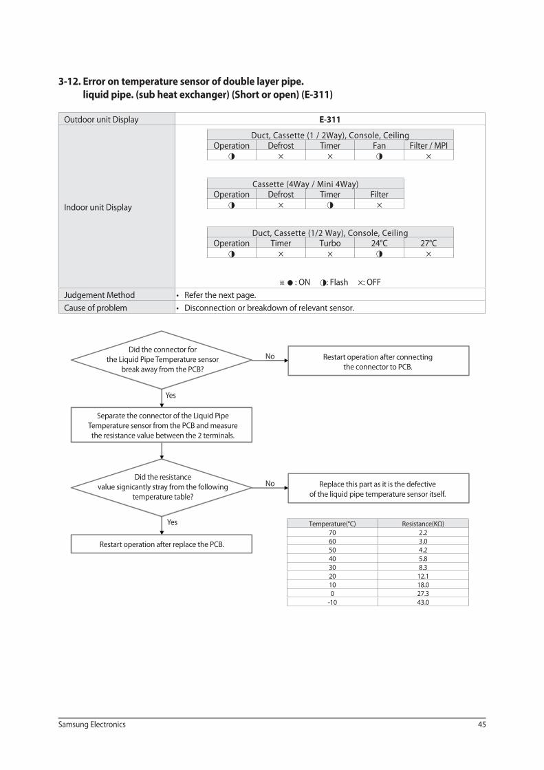
3-12. Error on temperature sensor of double layer pipe.
liquid pipe. (sub heat exchanger) (Short or open) (E-311)
Outdoor unit Display E-311
Indoor unit Display
Duct, Cassette (1 / 2Way), Console, Ceiling Operation Defrost Timer Fan Filter / MPI◑ × × ◑ ×
Cassette (4Way / Mini 4Way) Operation Defrost Timer Filter◑ × ◑ ×
Duct, Cassette (1/2 Way), Console, Ceiling Operation Timer Turbo 24°C 27°C ◑ × × ◑ ×
※ ● : ON ◑: Flash ×: OFF
Judgement Method
Cause of problem
Temperature(°C) Resistance(KΩ)70 2.2 60 3.0 50 4.2 40 5.8 30 8.3 20 12.110 18.0 0 27.3
-10 43.0
Did the connector for
the Liquid Pipe Temperature sensor
break away from the PCB?
Separate the connector of the Liquid Pipe
Temperature sensor from the PCB and measure
the resistance value between the 2 terminals.
Did the resistance
value signicantly stray from the following
temperature table?
Restart operation after replace the PCB.
Restart operation after connecting
the connector to PCB.
Replace this part as it is the defective
of the liquid pipe temperature sensor itself.
Yes
No
Yes
No
46 Samsung Electronics
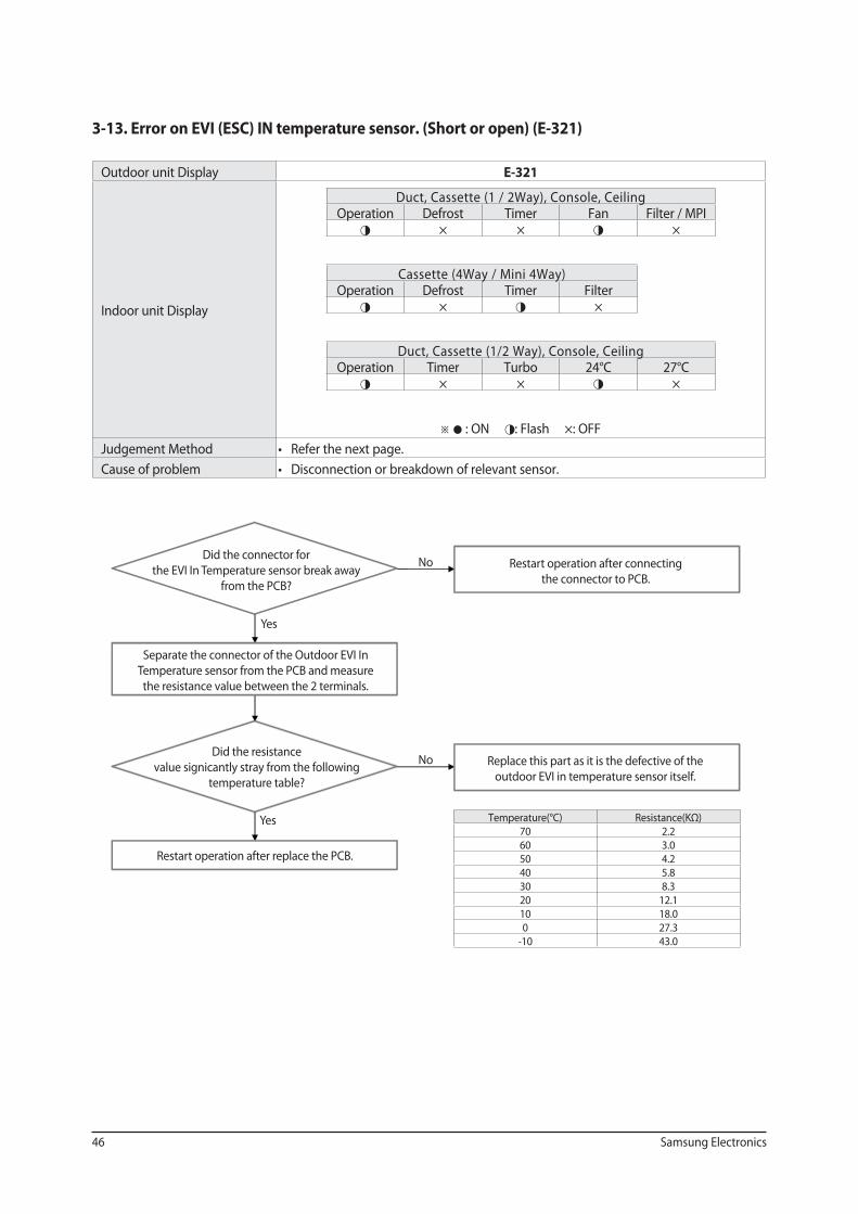
3-13. Error on EVI (ESC) IN temperature sensor. (Short or open) (E-321)
Outdoor unit Display E-321
Indoor unit Display
Duct, Cassette (1 / 2Way), Console, Ceiling Operation Defrost Timer Fan Filter / MPI◑ × × ◑ ×
Cassette (4Way / Mini 4Way) Operation Defrost Timer Filter◑ × ◑ ×
Duct, Cassette (1/2 Way), Console, Ceiling Operation Timer Turbo 24°C 27°C ◑ × × ◑ ×
※ ● : ON ◑: Flash ×: OFF
Judgement Method
Cause of problem
Temperature(°C) Resistance(KΩ)70 2.2 60 3.0 50 4.2 40 5.8 30 8.3 20 12.110 18.0 0 27.3
-10 43.0
Did the connector for
the EVI In Temperature sensor break away
from the PCB?
Separate the connector of the Outdoor EVI In
Temperature sensor from the PCB and measure
the resistance value between the 2 terminals.
Did the resistance
value signicantly stray from the following
temperature table?
Restart operation after replace the PCB.
Restart operation after connecting
the connector to PCB.
Replace this part as it is the defective of the
outdoor EVI in temperature sensor itself.
Yes
No
Yes
No
Samsung Electronics 47
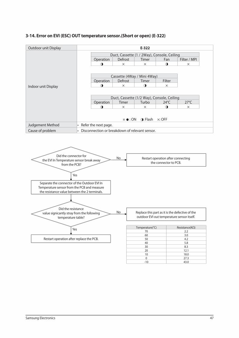
3-14. Error on EVI (ESC) OUT temperature sensor.(Short or open) (E-322)
Outdoor unit Display E-322
Indoor unit Display
Duct, Cassette (1 / 2Way), Console, Ceiling Operation Defrost Timer Fan Filter / MPI◑ × × ◑ ×
Cassette (4Way / Mini 4Way) Operation Defrost Timer Filter◑ × ◑ ×
Duct, Cassette (1/2 Way), Console, Ceiling Operation Timer Turbo 24°C 27°C ◑ × × ◑ ×
※ ● : ON ◑: Flash ×: OFF
Judgement Method
Cause of problem
Temperature(°C) Resistance(KΩ)70 2.2 60 3.0 50 4.2 40 5.8 30 8.3 20 12.110 18.0 0 27.3
-10 43.0
Did the connector for
the EVI In Temperature sensor break away
from the PCB?
Separate the connector of the Outdoor EVI In
Temperature sensor from the PCB and measure
the resistance value between the 2 terminals.
Did the resistance
value signicantly stray from the following
temperature table?
Restart operation after replace the PCB.
Restart operation after connecting
the connector to PCB.
Replace this part as it is the defective of the
outdoor EVI out temperature sensor itself.
Yes
No
Yes
No
48 Samsung Electronics
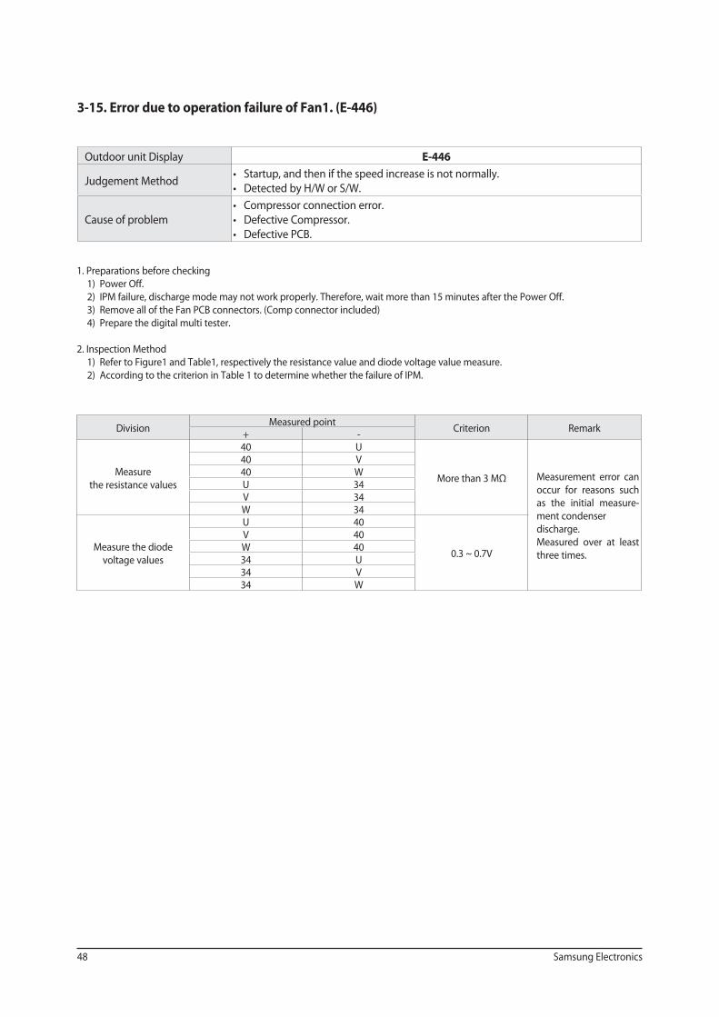
3-15. Error due to operation failure of Fan1. (E-446)
Outdoor unit Display E-446
Judgement Method
Cause of problem
1. Preparations before checking
1) Power Off.
2) IPM failure, discharge mode may not work properly. Therefore, wait more than 15 minutes after the Power Off.
3) Remove all of the Fan PCB connectors. (Comp connector included)
4) Prepare the digital multi tester.
2. Inspection Method
1) Refer to Figure1 and Table1, respectively the resistance value and diode voltage value measure.
2) According to the criterion in Table 1 to determine whether the failure of IPM.
Division Measured point
Criterion Remark + -
Measure
the resistance values
40 U
More than 3 MΩ Measurement error can
occur for reasons such
as the initial measure-
ment condenser
discharge.
Measured over at least
three times.
40 V 40 W U 34 V 34 W 34
Measure the diode
voltage values
U 40
0.3 ~ 0.7V
V 40 W 40 34 U 34 V 34 W
Samsung Electronics 49
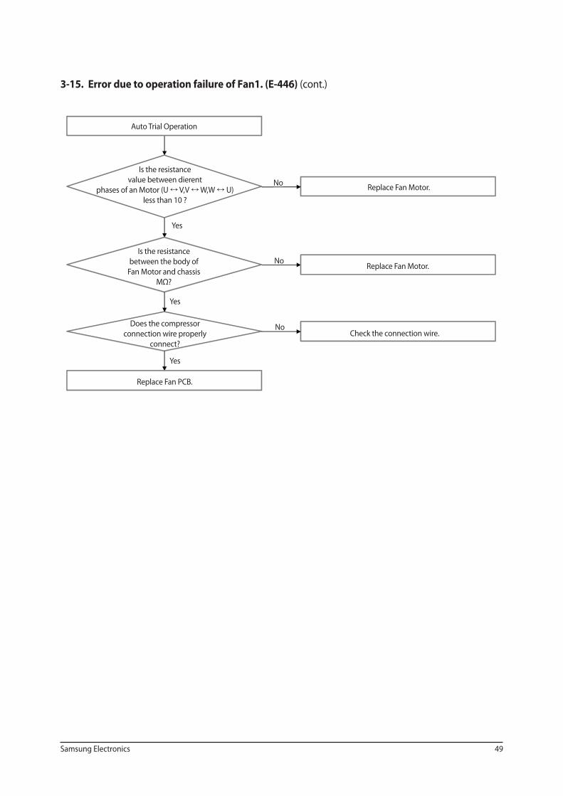
3-15. Error due to operation failure of Fan1. (E-446) (cont.)
Auto Trial Operation
Is the resistance
value between dierent
phases of an Motor (U V,V W,W U)
less than 10 ?
Is the resistance
between the body of
Fan Motor and chassis
MΩ?
Does the compressor
connection wire properly
connect?
Replace Fan PCB.
Replace Fan Motor.
Replace Fan Motor.
Check the connection wire.
Yes
No
Yes
Yes
No
No
50 Samsung Electronics
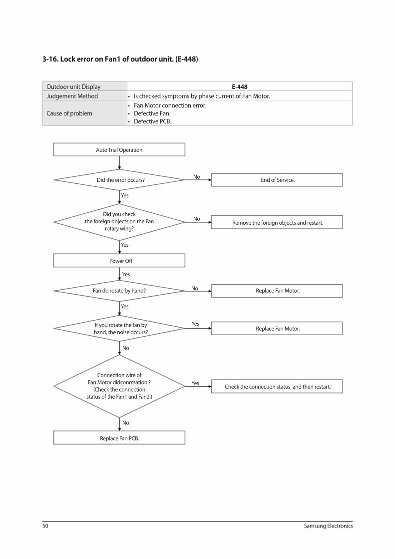
3-16. Lock error on Fan1 of outdoor unit. (E-448)
Outdoor unit Display E-448
Judgement Method
Cause of problem
Auto Trial Operation
Did the error occurs?
Did you check
the foreign objects on the Fan
rotary wing?
Power Off
Fan do rotate by hand?
If you rotate the fan by
hand, the noise occurs?
Connection wire of
Fan Motor didconrmation ?
(Check the connection
status of the Fan1 and Fan2.)
Replace Fan PCB.
End of Service.
Remove the foreign objects and restart.
Replace Fan Motor.
Replace Fan Motor.
Check the connection status, and then restart.
No
Yes
Yes
Yes
Yes
Yes
Yes
No
No
No
No
Samsung Electronics 51
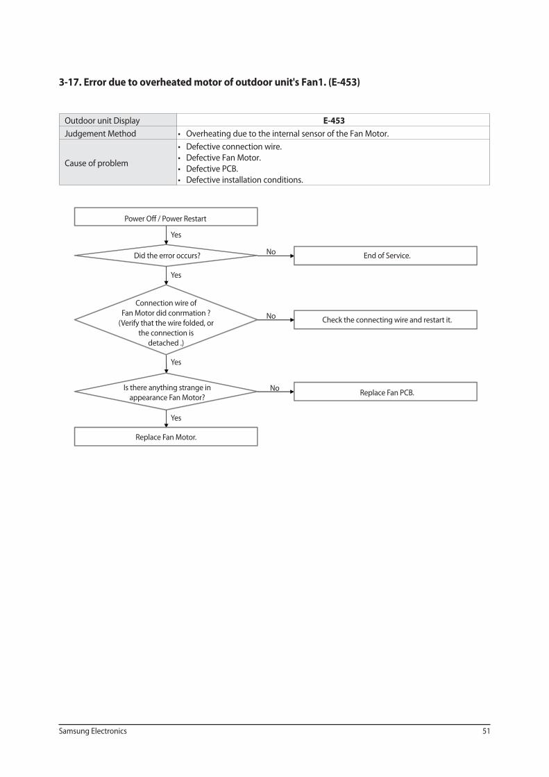
3-17. Error due to overheated motor of outdoor unit's Fan1. (E-453)
Outdoor unit Display E-453
Judgement Method
Cause of problem
Power Off / Power Restart
Did the error occurs?
Connection wire of
Fan Motor did conrmation ?
(Verify that the wire folded, or
the connection is
detached .)
Is there anything strange in
appearance Fan Motor?
Replace Fan Motor.
End of Service.
Check the connecting wire and restart it.
Replace Fan PCB.
Yes
No
Yes
Yes
Yes
No
No
52 Samsung Electronics
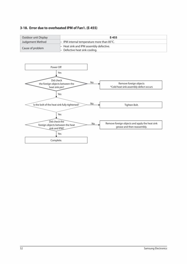
3-18. Error due to overheated IPM of Fan1. (E-455)
Outdoor unit Display E-455
Judgement Method
Cause of problem
Power Off
Did check
the foreign objects between the
heat sink pin?
Is the bolt of the heat sink fully tightened?
Did check the
foreign objects between the heat
sink and IPM?
Complete.
Remove foreign objects
*Cold heat sink assembly defect occurs
Tighten Bolt.
Remove foreign objects and apply the heat sink
grease and then reassembly.
Yes
No
Yes
Yes
Yes
No
No
Samsung Electronics 53
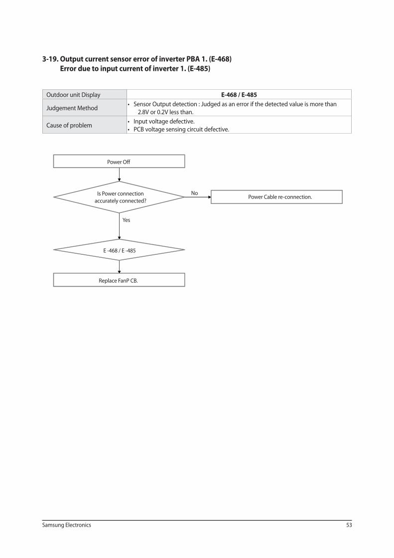
3-19. Output current sensor error of inverter PBA 1. (E-468)
Error due to input current of inverter 1. (E-485)
Outdoor unit Display E-468 / E-485
Judgement Method
2.8V or 0.2V less than.
Cause of problem
Power Off
Is Power connection
accurately connected?
E -468 / E -485
Replace FanP CB.
Power Cable re-connection.
Yes
No
54 Samsung Electronics
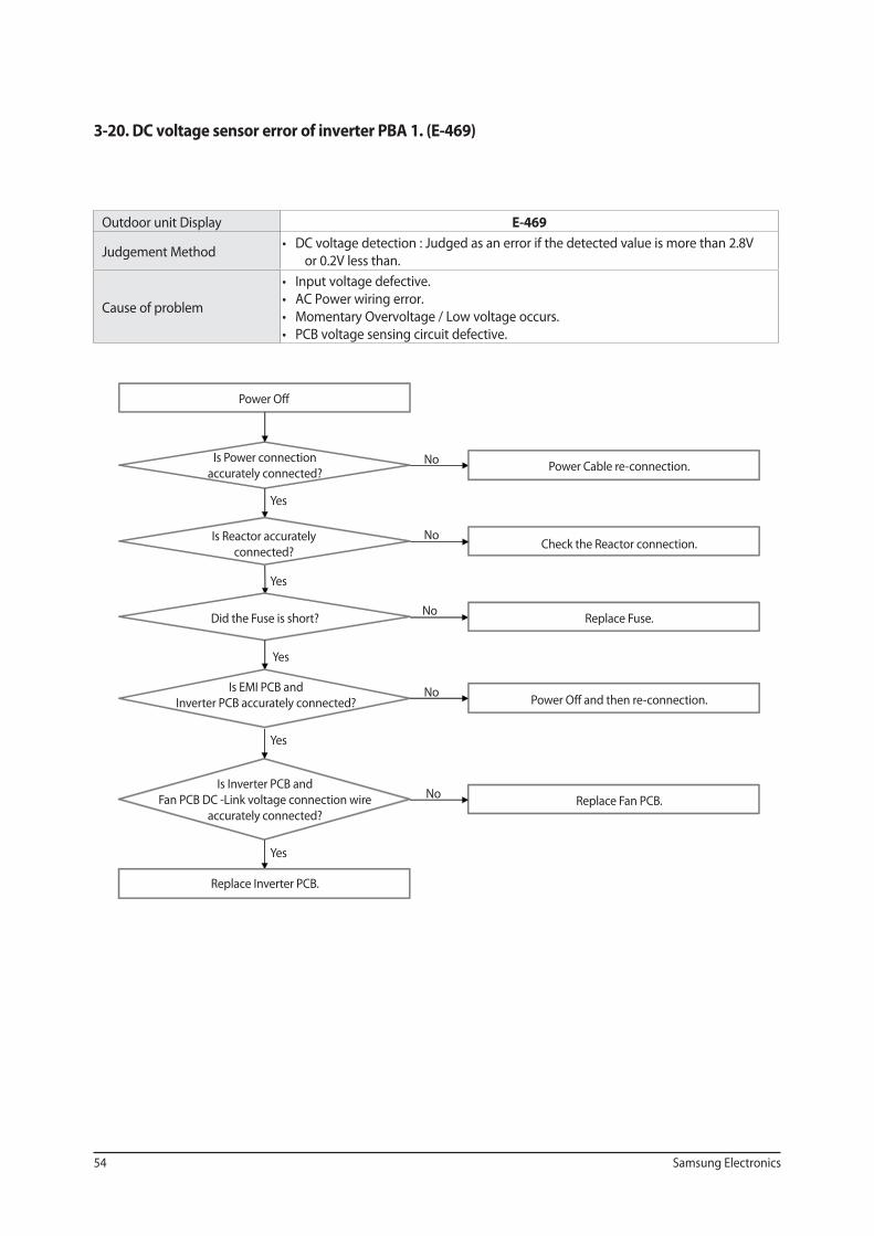
3-20. DC voltage sensor error of inverter PBA 1. (E-469)
Outdoor unit Display E-469
Judgement Method
or 0.2V less than.
Cause of problem
Power Off
Is Power connection
accurately connected?
Is Reactor accurately
connected?
Did the Fuse is short?
Is EMI PCB and
Inverter PCB accurately connected?
Is Inverter PCB and
Fan PCB DC -Link voltage connection wire
accurately connected?
Replace Inverter PCB.
Power Cable re-connection.
Check the Reactor connection.
Replace Fuse.
Power Off and then re-connection.
Replace Fan PCB.
Yes
No
Yes
Yes
Yes
Yes
No
No
No
No
Samsung Electronics 55
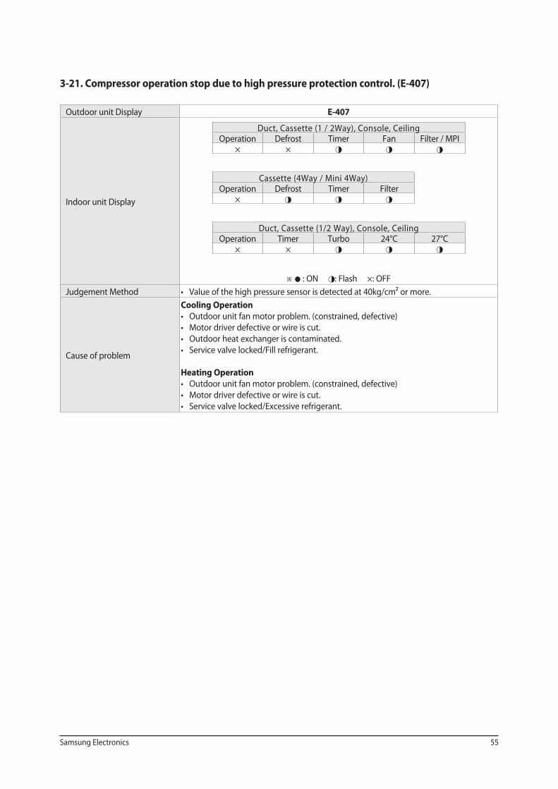
3-21. Compressor operation stop due to high pressure protection control. (E-407)
Outdoor unit Display E-407
Indoor unit Display
Duct, Cassette (1 / 2Way), Console, Ceiling Operation Defrost Timer Fan Filter / MPI
× × ◑ ◑ ◑
Cassette (4Way / Mini 4Way) Operation Defrost Timer Filter
× ◑ ◑ ◑
Duct, Cassette (1/2 Way), Console, Ceiling Operation Timer Turbo 24°C 27°C
× × ◑ ◑ ◑
※ ● : ON ◑: Flash ×: OFF
Judgement Method
Cause of problem
Cooling Operation
Heating Operation
56 Samsung Electronics
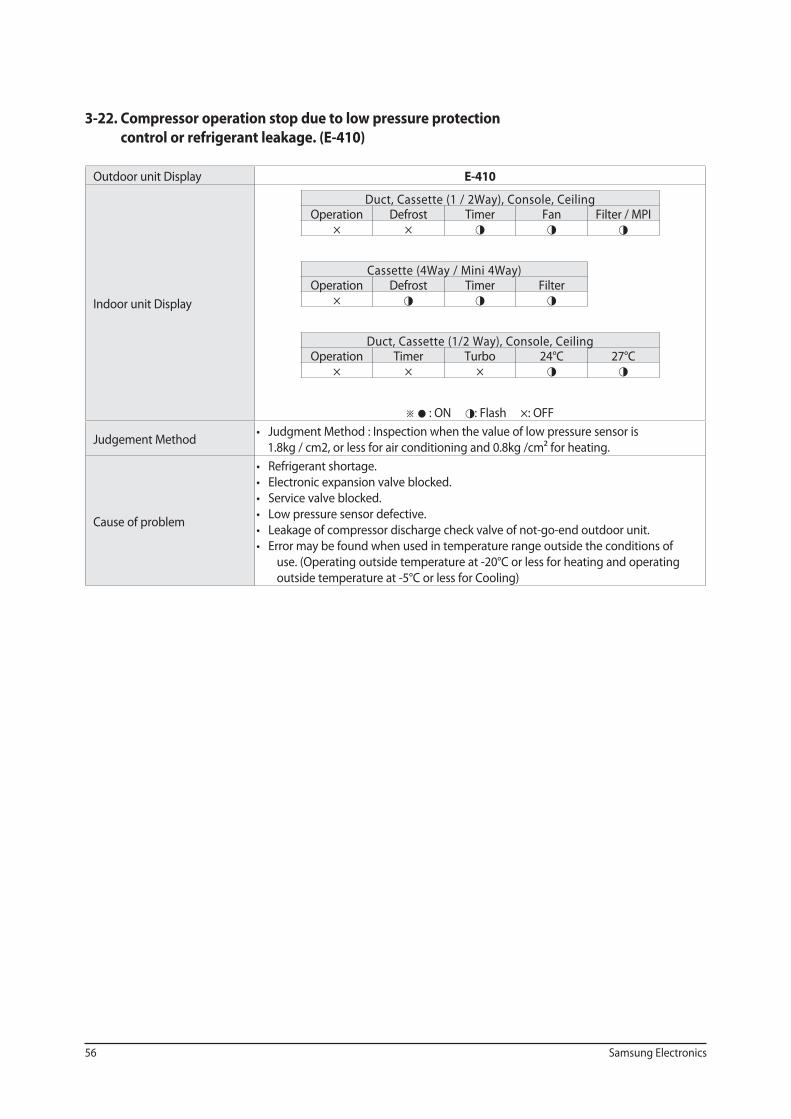
3-22. Compressor operation stop due to low pressure protection
control or refrigerant leakage. (E-410)
Outdoor unit Display E-410
Indoor unit Display
Duct, Cassette (1 / 2Way), Console, Ceiling Operation Defrost Timer Fan Filter / MPI
× × ◑ ◑ ◑
Cassette (4Way / Mini 4Way) Operation Defrost Timer Filter
× ◑ ◑ ◑
Duct, Cassette (1/2 Way), Console, Ceiling Operation Timer Turbo 24°C 27°C
× × × ◑ ◑
※ ● : ON ◑: Flash ×: OFF
Judgement Method
Cause of problem
use. (Operating outside temperature at -20°C or less for heating and operating
outside temperature at -5°C or less for Cooling)
Samsung Electronics 57
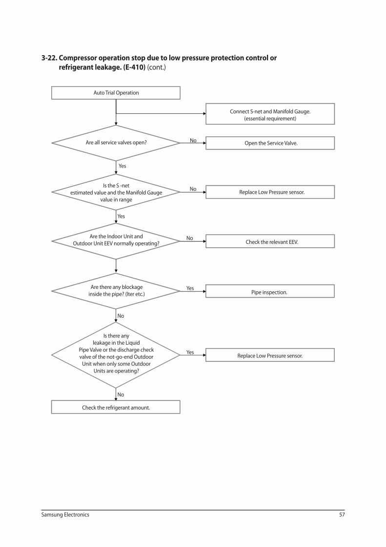
3-22. Compressor operation stop due to low pressure protection control or
refrigerant leakage. (E-410) (cont.)
Auto Trial Operation
Are all service valves open?
Is the S -net
estimated value and the Manifold Gauge
value in range
Are the Indoor Unit and
Outdoor Unit EEV normally operating?
Are there any blockage
inside the pipe? (lter etc.)
Is there any
leakage in the Liquid
Pipe Valve or the discharge check
valve of the not-go-end Outdoor
Unit when only some Outdoor
Units are operating?
Connect S-net and Manifold Gauge.
(essential requirement)
Open the Service Valve.
Replace Low Pressure sensor.
Check the relevant EEV.
Pipe inspection.
Replace Low Pressure sensor.
Yes
No
Yes
Yes
No
No
Yes
No
No
Check the refrigerant amount.
58 Samsung Electronics
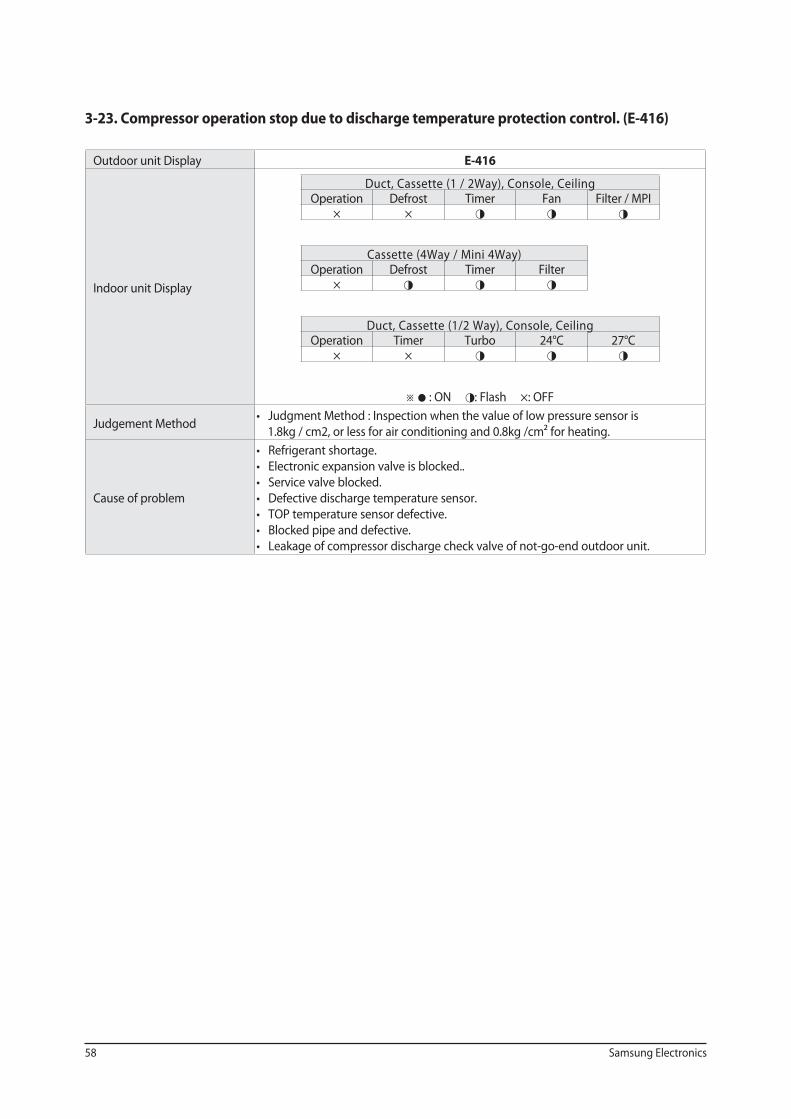
3-23. Compressor operation stop due to discharge temperature protection control. (E-416)
Outdoor unit Display E-416
Indoor unit Display
Duct, Cassette (1 / 2Way), Console, Ceiling Operation Defrost Timer Fan Filter / MPI
× × ◑ ◑ ◑
Cassette (4Way / Mini 4Way) Operation Defrost Timer Filter
× ◑ ◑ ◑
Duct, Cassette (1/2 Way), Console, Ceiling Operation Timer Turbo 24°C 27°C
× × ◑ ◑ ◑
※ ● : ON ◑: Flash ×: OFF
Judgement Method
Cause of problem
Samsung Electronics 59
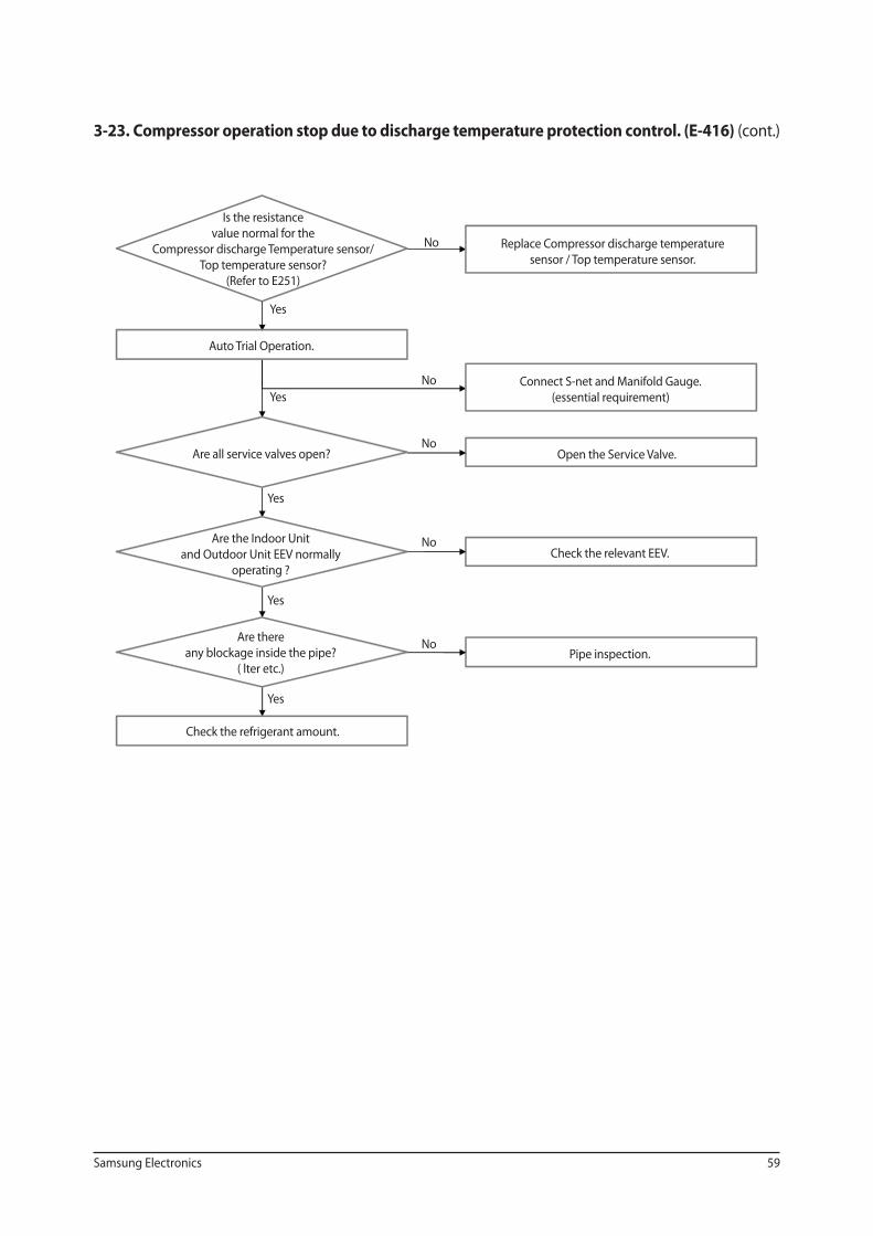
3-23. Compressor operation stop due to discharge temperature protection control. (E-416) (cont.)
Is the resistance
value normal for the
Compressor discharge Temperature sensor/
Top temperature sensor?
(Refer to E251)
Auto Trial Operation.
Are all service valves open?
Are the Indoor Unit
and Outdoor Unit EEV normally
operating ?
Are there
any blockage inside the pipe?
( lter etc.)
Check the refrigerant amount.
Replace Compressor discharge temperature
sensor / Top temperature sensor.
Connect S-net and Manifold Gauge.
(essential requirement)
Open the Service Valve.
Check the relevant EEV.
Pipe inspection.
Yes
No
Yes
Yes
Yes
Yes
No
No
No
No
60 Samsung Electronics
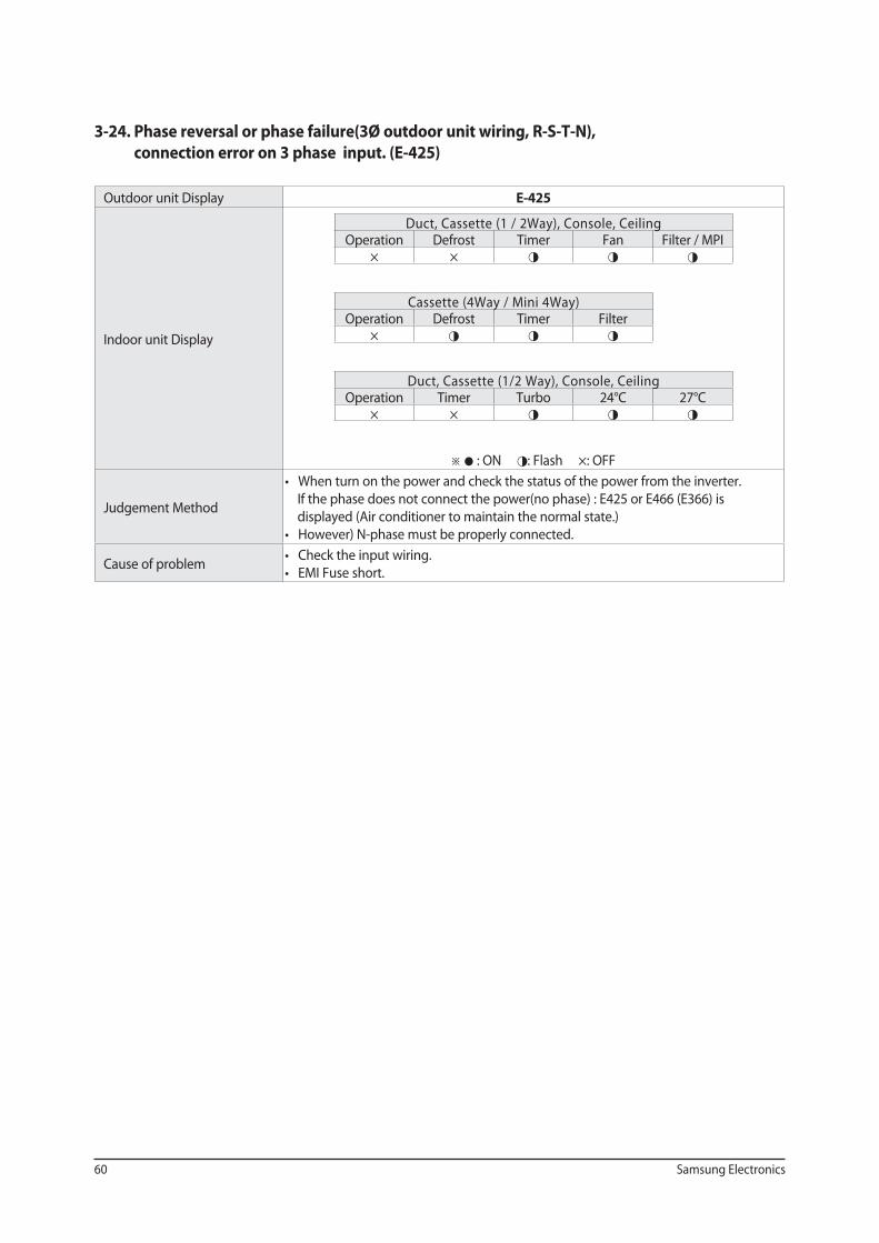
3-24. Phase reversal or phase failure(3Ø outdoor unit wiring, R-S-T-N),
connection error on 3 phase input. (E-425)
Outdoor unit Display E-425
Indoor unit Display
Duct, Cassette (1 / 2Way), Console, Ceiling Operation Defrost Timer Fan Filter / MPI
× × ◑ ◑ ◑
Cassette (4Way / Mini 4Way) Operation Defrost Timer Filter
× ◑ ◑ ◑
Duct, Cassette (1/2 Way), Console, Ceiling Operation Timer Turbo 24°C 27°C
× × ◑ ◑ ◑
※ ● : ON ◑: Flash ×: OFF
Judgement Method If the phase does not connect the power(no phase) : E425 or E466 (E366) is
displayed (Air conditioner to maintain the normal state.)
Cause of problem
Samsung Electronics 61
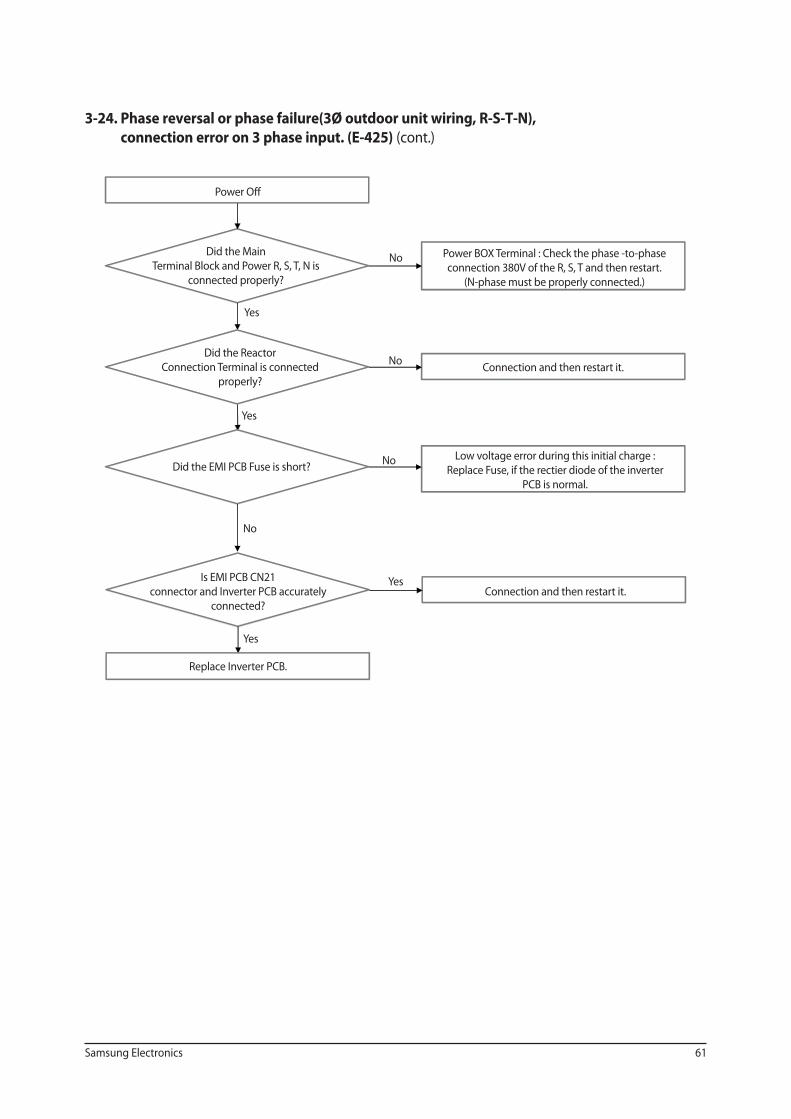
3-24. Phase reversal or phase failure(3Ø outdoor unit wiring, R-S-T-N),
connection error on 3 phase input. (E-425) (cont.)
Power Off
Did the Main
Terminal Block and Power R, S, T, N is
connected properly?
Did the Reactor
Connection Terminal is connected
properly?
Did the EMI PCB Fuse is short?
Is EMI PCB CN21
connector and Inverter PCB accurately
connected?
Replace Inverter PCB.
Power BOX Terminal : Check the phase -to-phase
connection 380V of the R, S, T and then restart.
(N-phase must be properly connected.)
Connection and then restart it.
Low voltage error during this initial charge :
Replace Fuse, if the rectier diode of the inverter
PCB is normal.
Connection and then restart it.
Yes
No
Yes
Yes
Yes
No
No
No
62 Samsung Electronics
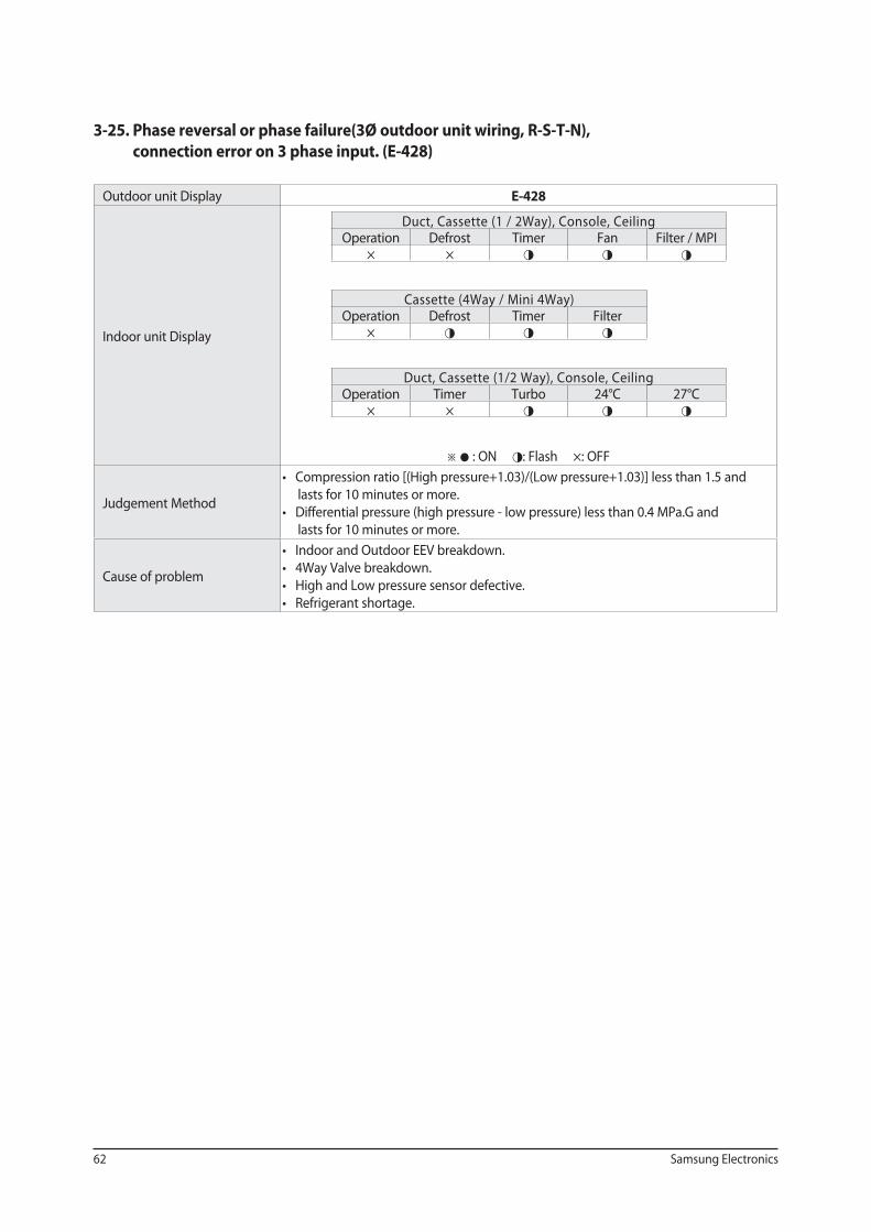
3-25. Phase reversal or phase failure(3Ø outdoor unit wiring, R-S-T-N),
connection error on 3 phase input. (E-428)
Outdoor unit Display E-428
Indoor unit Display
Duct, Cassette (1 / 2Way), Console, Ceiling Operation Defrost Timer Fan Filter / MPI
× × ◑ ◑ ◑
Cassette (4Way / Mini 4Way) Operation Defrost Timer Filter
× ◑ ◑ ◑
Duct, Cassette (1/2 Way), Console, Ceiling Operation Timer Turbo 24°C 27°C
× × ◑ ◑ ◑
※ ● : ON ◑: Flash ×: OFF
Judgement Method
lasts for 10 minutes or more.
lasts for 10 minutes or more.
Cause of problem
Samsung Electronics 63
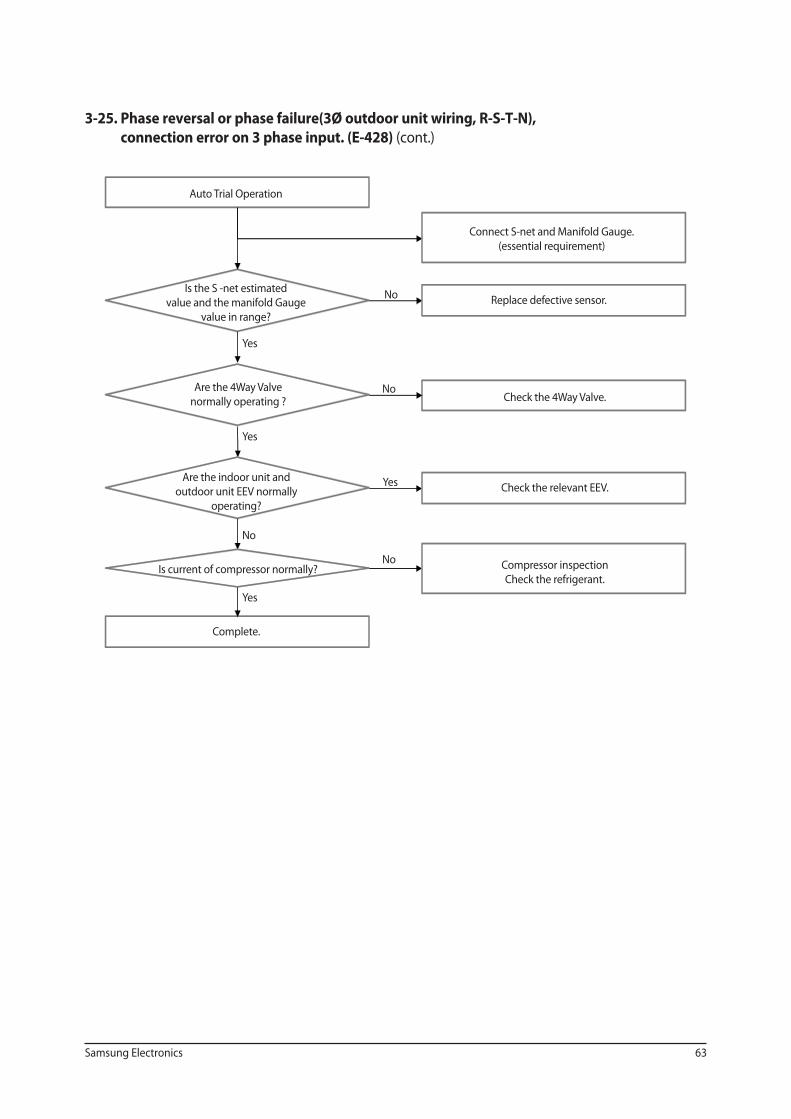
3-25. Phase reversal or phase failure(3Ø outdoor unit wiring, R-S-T-N),
connection error on 3 phase input. (E-428) (cont.)
Auto Trial Operation
Is the S -net estimated
value and the manifold Gauge
value in range?
Are the 4Way Valve
normally operating ?
Are the indoor unit and
outdoor unit EEV normally
operating?
Is current of compressor normally?
Complete.
Connect S-net and Manifold Gauge.
(essential requirement)
Replace defective sensor.
Check the 4Way Valve.
Check the relevant EEV.
Compressor inspection
Check the refrigerant.
Yes
No
Yes
Yes
Yes
No
No
No
64 Samsung Electronics
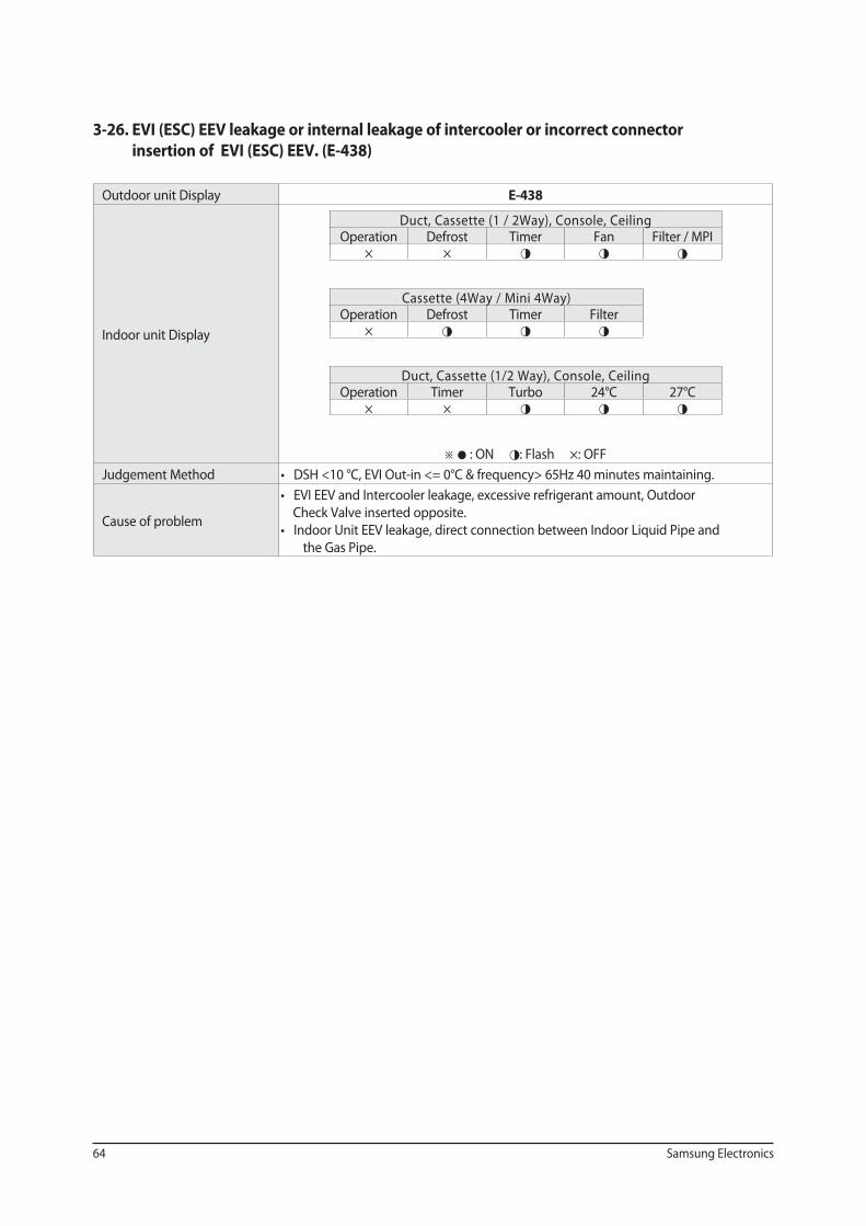
3-26. EVI (ESC) EEV leakage or internal leakage of intercooler or incorrect connector
insertion of EVI (ESC) EEV. (E-438)
Outdoor unit Display E-438
Indoor unit Display
Duct, Cassette (1 / 2Way), Console, Ceiling Operation Defrost Timer Fan Filter / MPI
× × ◑ ◑ ◑
Cassette (4Way / Mini 4Way) Operation Defrost Timer Filter
× ◑ ◑ ◑
Duct, Cassette (1/2 Way), Console, Ceiling Operation Timer Turbo 24°C 27°C
× × ◑ ◑ ◑
※ ● : ON ◑: Flash ×: OFF
Judgement Method
Cause of problem
Check Valve inserted opposite.
the Gas Pipe.
Samsung Electronics 65
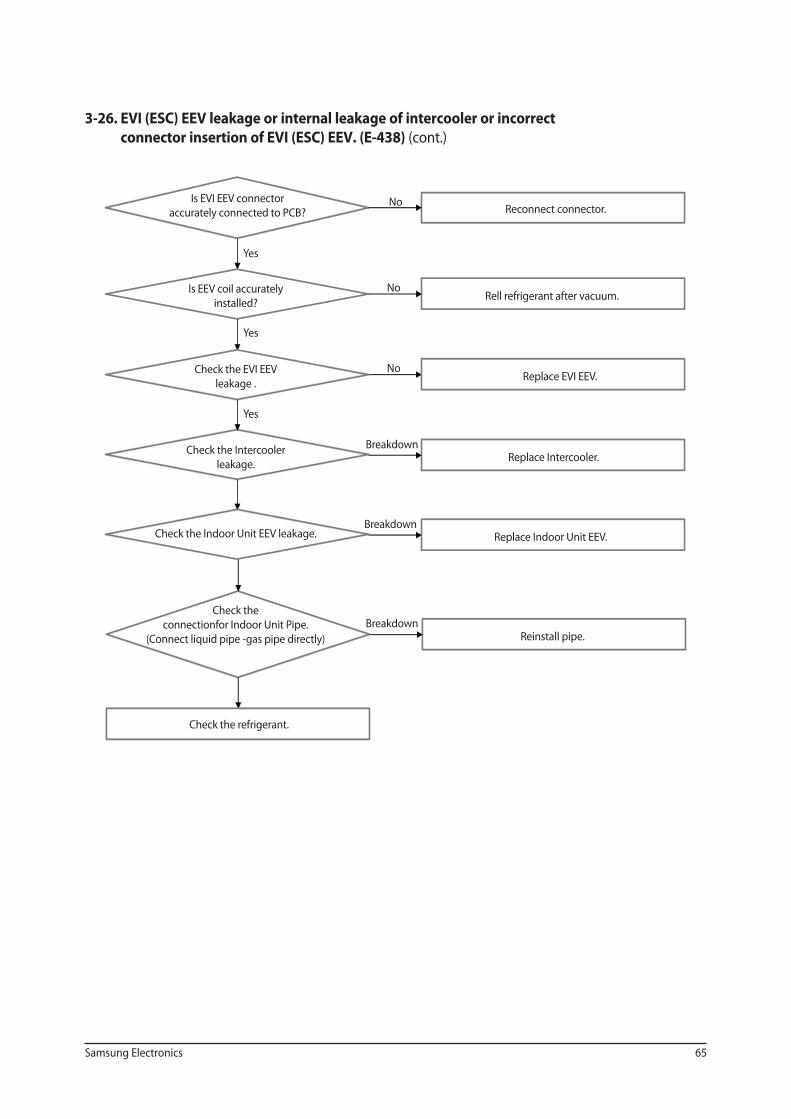
3-26. EVI (ESC) EEV leakage or internal leakage of intercooler or incorrect
connector insertion of EVI (ESC) EEV. (E-438) (cont.)
Is EVI EEV connector
accurately connected to PCB?
Is EEV coil accurately
installed?
Check the EVI EEV
leakage .
Check the Intercooler
leakage.
Check the Indoor Unit EEV leakage.
Check the
connectionfor Indoor Unit Pipe.
(Connect liquid pipe -gas pipe directly)
Check the refrigerant.
Reconnect connector.
Rell refrigerant after vacuum.
Replace EVI EEV.
Replace Intercooler.
Replace Indoor Unit EEV.
Reinstall pipe.
Yes
Yes
Yes
No
No
No
Breakdown
Breakdown
Breakdown
66 Samsung Electronics
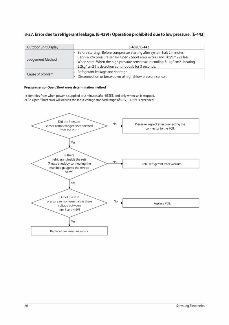
3-27. Error due to refrigerant leakage. (E-439) / Operation prohibited due to low pressure. (E-443)
Outdoor unit Display E-439 / E-443
Judgement Method (High & low pressure sensor Open / Short error occurs and 1kg/cm2 or less)
When start : When the high pressure sensor value(cooling 3.1kg/ cm2 , heating
2.2kg/ cm2 ) is detection continuously for 3 seconds.
Cause of problem
Pressure sensor Open/Short error determination method
1) Identifies from when power is supplied or 2 minutes after RESET, and only when set is stopped.
2) An Open/Short error will occur if the input voltage standard range of 0.5V ~ 4.95V is exceeded.
Did the Pressure
sensor connector get disconnected
from the PCB?
Is there
refrigerant inside the set?
(Please check by connecting the
manifold gauge to the service
valve)
Out of the PCB
pressure sensor terminals, is there
voltage between
pins 3 and 4 5V?
Replace Low Pressure sensor.
Please re inspect after connecting the
connector to the PCB.
Refill refrigerant after vacuum.
Replace PCB.
Yes
No
Yes
Yes
No
No
Samsung Electronics 67
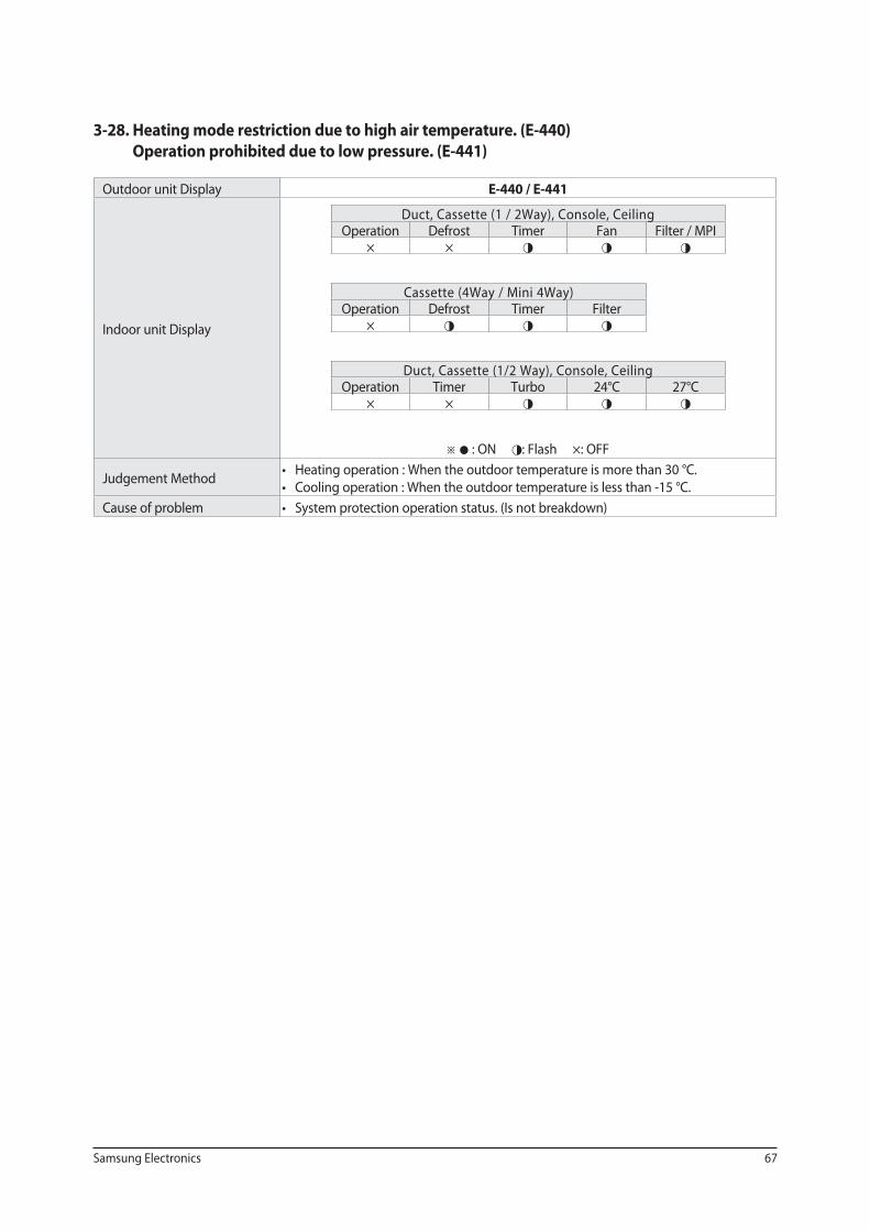
3-28. Heating mode restriction due to high air temperature. (E-440)
Operation prohibited due to low pressure. (E-441)
Outdoor unit Display E-440 / E-441
Indoor unit Display
Duct, Cassette (1 / 2Way), Console, Ceiling Operation Defrost Timer Fan Filter / MPI
× × ◑ ◑ ◑
Cassette (4Way / Mini 4Way) Operation Defrost Timer Filter
× ◑ ◑ ◑
Duct, Cassette (1/2 Way), Console, Ceiling Operation Timer Turbo 24°C 27°C
× × ◑ ◑ ◑
※ ● : ON ◑: Flash ×: OFF
Judgement Method
Cause of problem
68 Samsung Electronics
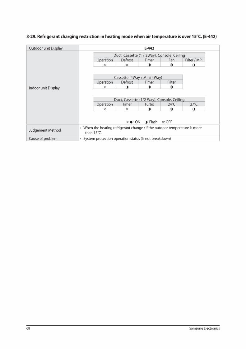
3-29. Refrigerant charging restriction in heating mode when air temperature is over 15°C. (E-442)
Outdoor unit Display E-442
Indoor unit Display
Duct, Cassette (1 / 2Way), Console, Ceiling Operation Defrost Timer Fan Filter / MPI
× × ◑ ◑ ◑
Cassette (4Way / Mini 4Way) Operation Defrost Timer Filter
× ◑ ◑ ◑
Duct, Cassette (1/2 Way), Console, Ceiling Operation Timer Turbo 24°C 27°C
× × ◑ ◑ ◑
※ ● : ON ◑: Flash ×: OFF
Judgement Method
than 15°C.
Cause of problem
Samsung Electronics 69
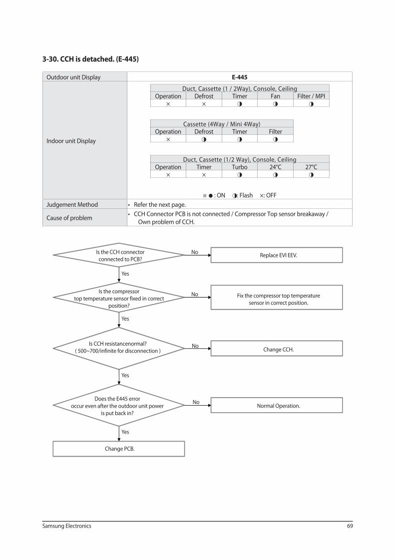
3-30. CCH is detached. (E-445)
Outdoor unit Display E-445
Indoor unit Display
Duct, Cassette (1 / 2Way), Console, Ceiling Operation Defrost Timer Fan Filter / MPI
× × ◑ ◑ ◑
Cassette (4Way / Mini 4Way) Operation Defrost Timer Filter
× ◑ ◑ ◑
Duct, Cassette (1/2 Way), Console, Ceiling Operation Timer Turbo 24°C 27°C
× × ◑ ◑ ◑
※ ● : ON ◑: Flash ×: OFF
Judgement Method
Cause of problem
Own problem of CCH.
Is the CCH connector
connected to PCB?
Is the compressor
top temperature sensor fixed in correct
position?
Is CCH resistancenormal?
( 500~700/infinite for disconnection )
Does the E445 error
occur even after the outdoor unit power
is put back in?
Change PCB.
Replace EVI EEV.
Fix the compressor top temperature
sensor in correct position.
Change CCH.
Normal Operation.
Yes
No
Yes
Yes
Yes
No
No
No
70 Samsung Electronics
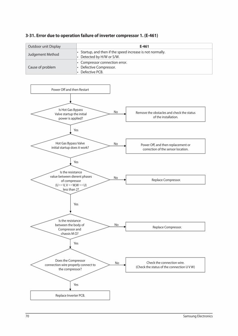
3-31. Error due to operation failure of inverter compressor 1. (E-461)
Outdoor unit Display E-461
Judgement Method
Cause of problem
Power Off and then Restart
Is Hot Gas Bypass
Valve startup the initial
power is applied?
Hot Gas Bypass Valve
initial startup does it work?
Is the resistance
value between dierent phases
of compressor
(U V, V W,W U)
less than 2?
Is the resistance
between the body of
Compressor and
chassis M Ω?
Does the Compressor
connection wire properly connect to
the compressor?
Replace Inverter PCB.
Remove the obstacles and check the status
of the installation.
Power Off, and then replacement or
correction of the sensor location.
Replace Compressor.
Replace Compressor.
Check the connection wire.
(Check the status of the connection U V W)
Yes
No
Yes
Yes
Yes
Yes
No
No
No
No
Samsung Electronics 71
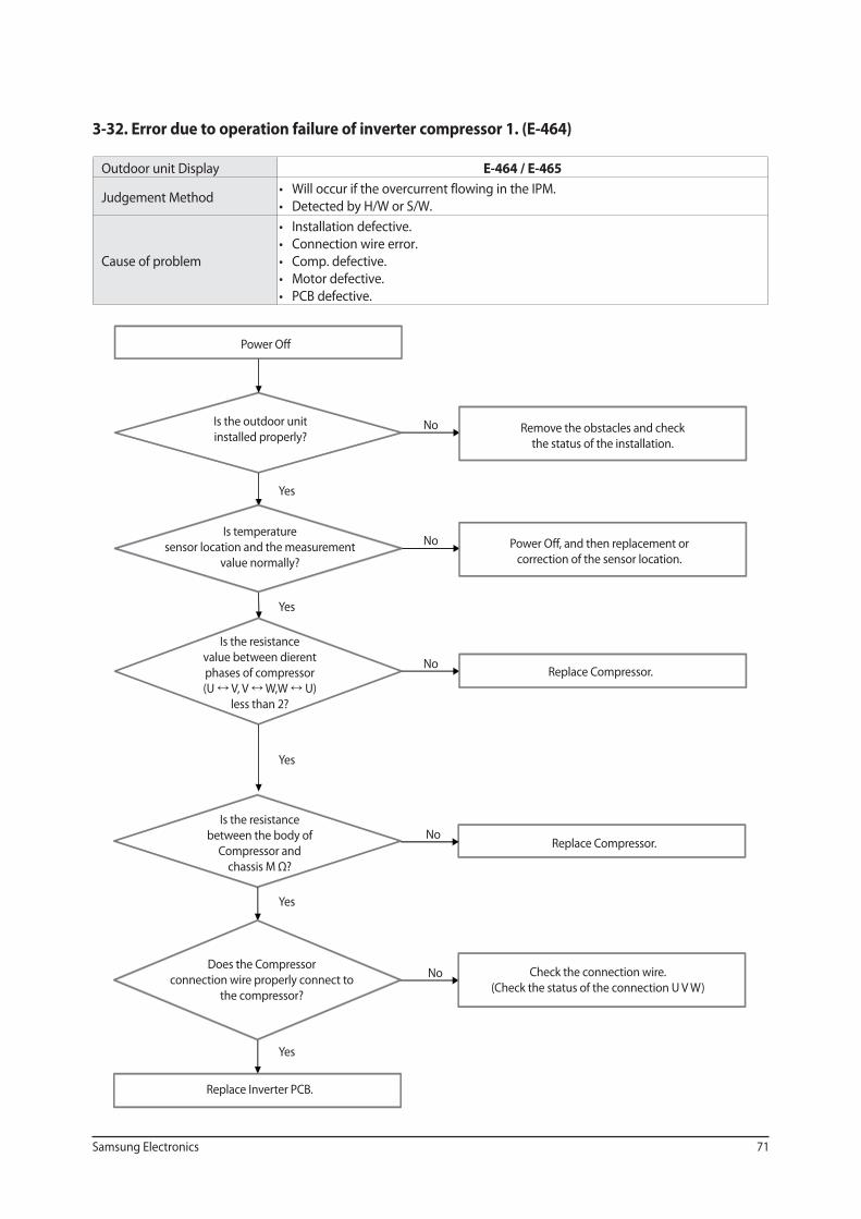
3-32. Error due to operation failure of inverter compressor 1. (E-464)
Outdoor unit Display E-464 / E-465
Judgement Method
Cause of problem
Power Off
Is the outdoor unit
installed properly?
Is temperature
sensor location and the measurement
value normally?
Is the resistance
value between dierent
phases of compressor
(U V, V W,W U)
less than 2?
Is the resistance
between the body of
Compressor and
chassis M Ω?
Does the Compressor
connection wire properly connect to
the compressor?
Replace Inverter PCB.
Remove the obstacles and check
the status of the installation.
Power Off, and then replacement or
correction of the sensor location.
Replace Compressor.
Replace Compressor.
Check the connection wire.
(Check the status of the connection U V W)
Yes
No
Yes
Yes
Yes
Yes
No
No
No
No
72 Samsung Electronics
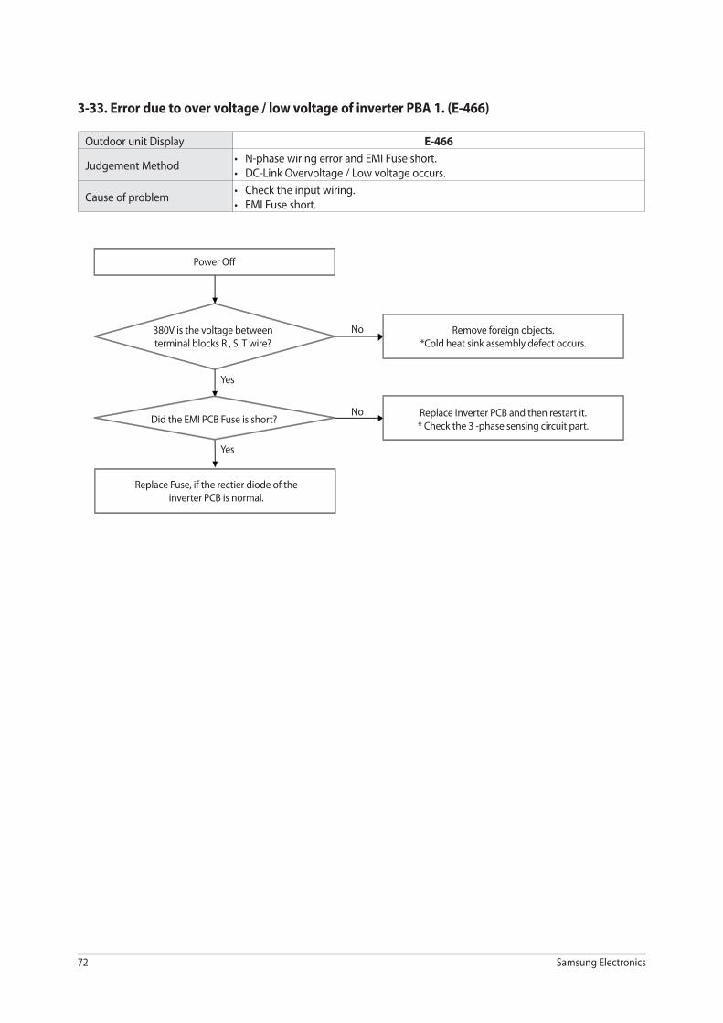
3-33. Error due to over voltage / low voltage of inverter PBA 1. (E-466)
Outdoor unit Display E-466
Judgement Method
Cause of problem
Power Off
380V is the voltage between
terminal blocks R , S, T wire?
Did the EMI PCB Fuse is short?
Replace Fuse, if the rectier diode of the
inverter PCB is normal.
Remove foreign objects.
*Cold heat sink assembly defect occurs.
Replace Inverter PCB and then restart it.
* Check the 3 -phase sensing circuit part.
Yes
No
Yes
No
Samsung Electronics 73
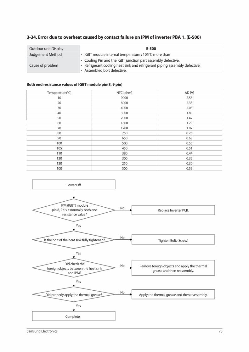
3-34. Error due to overheat caused by contact failure on IPM of inverter PBA 1. (E-500)
Outdoor unit Display E-500
Judgement Method
Cause of problem
Both end resistance values of IGBT module pin(8, 9 pin)
Temperature(°C)
10 9000 2.58
20 6000 2.33
30 4000 2.03
40 3000 1.80
50 2000 1.47
60 1600 1.29
70 1200 1.07
80 750 0.76
90 650 0.68
100 500 0.55
105 450 0.51
110 380 0.44
120 300 0.35
130 250 0.30
100 500 0.55
Power Off
IPM (IGBT) module
pin 8, 9 : Is it normally both end
resistance value?
Did check the
foreign objects between the heat sink
and IPM?
Did properly apply the thermal grease?
Is the bolt of the heat sink fully tightened?
Complete.
Replace Inverter PCB.
Tighten Bolt. (Screw)
Remove foreign objects and apply the thermal
grease and then reassembly.
Apply the thermal grease and then reassembly.
Yes
No
Yes
Yes
Yes
No
No
No
74 Samsung Electronics
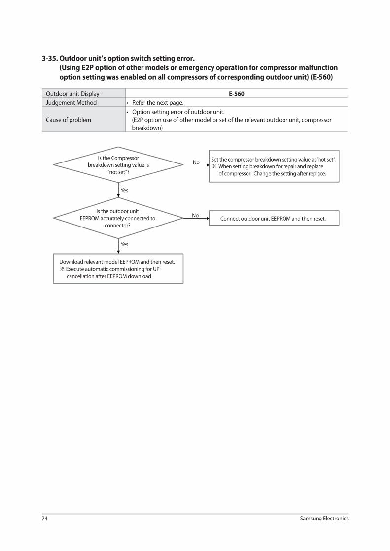
3-35. Outdoor unit’s option switch setting error.
(Using E2P option of other models or emergency operation for compressor malfunction
option setting was enabled on all compressors of corresponding outdoor unit) (E-560)
Outdoor unit Display E-560
Judgement Method
Cause of problem (E2P option use of other model or set of the relevant outdoor unit, compressor
breakdown)
Is the Compressor
breakdown setting value is
“not set”?
Is the outdoor unit
EEPROM accurately connected to
connector?
Download relevant model EEPROM and then reset.
Execute automatic commissioning for UP
cancellation after EEPROM download
Set the compressor breakdown setting value as“not set”.
When setting breakdown for repair and replace
of compressor : Change the setting after replace.
Connect outdoor unit EEPROM and then reset.
Yes
No
Yes
No
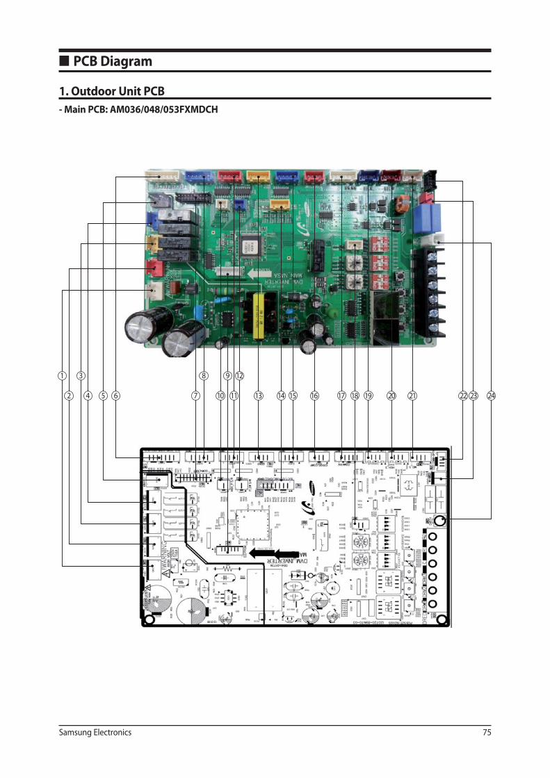
Samsung Electronics 75
■ PCB Diagram
1. Outdoor Unit PCB
- Main PCB: AM036/048/053FXMDCH
2
3
4 5 6 7
8
10
9
11
12
13 14 15 16 17 18 19 20 21 22 23 24
1
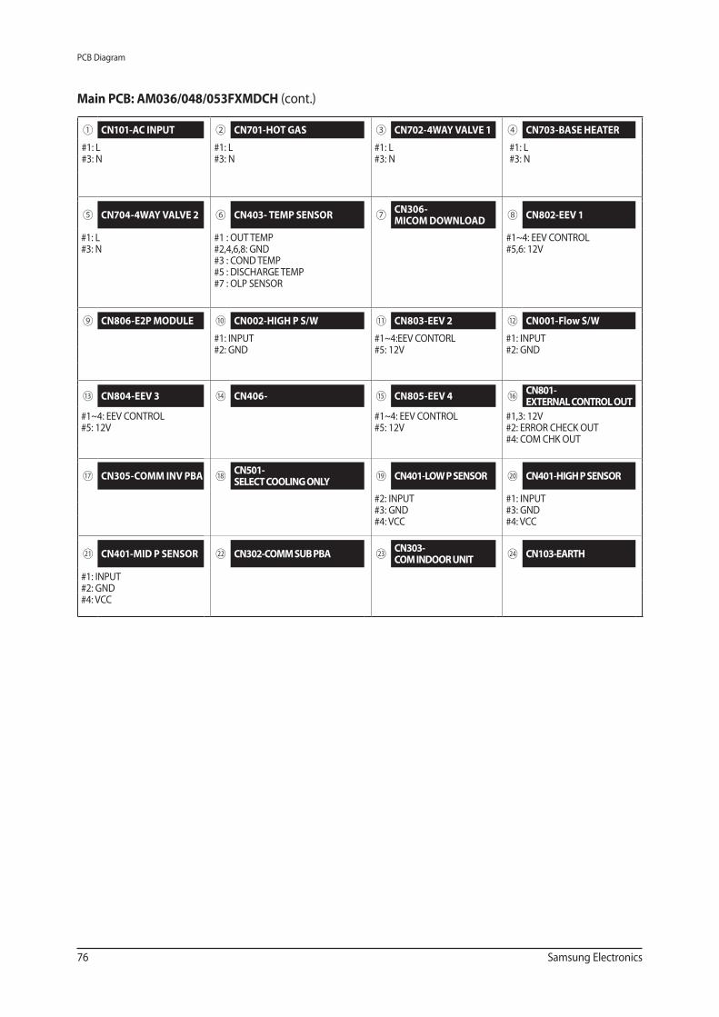
76 Samsung Electronics
PCB Diagram
① CN101-AC INPUT ② CN701-HOT GAS ③ CN702-4WAY VALVE 1 ④ CN703-BASE HEATER
#1: L#3: N
#1: L#3: N
#1: L#3: N
#1: L#3: N
⑤ CN704-4WAY VALVE 2 ⑥ CN403- TEMP SENSOR ⑦ CN306- MICOM DOWNLOAD
⑧ CN802-EEV 1
#1: L#3: N
#1 : OUT TEMP#2,4,6,8: GND#3 : COND TEMP#5 : DISCHARGE TEMP#7 : OLP SENSOR
#1~4: EEV CONTROL#5,6: 12V
⑨ CN806-E2P MODULE ⑩ CN002-HIGH P S/W ⑪ CN803-EEV 2 ⑫ CN001-Flow S/W
#1: INPUT#2: GND
#1~4:EEV CONTORL#5: 12V
#1: INPUT#2: GND
⑬ CN804-EEV 3 ⑭ CN406- ⑮ CN805-EEV 4 ⑯ CN801- EXTERNAL CONTROL OUT
#1~4: EEV CONTROL#5: 12V
#1~4: EEV CONTROL#5: 12V
#1,3: 12V#2: ERROR CHECK OUT#4: COM CHK OUT
⑰ CN305-COMM INV PBA ⑱ CN501- SELECT COOLING ONLY
⑲ CN401-LOW P SENSOR ⑳ CN401-HIGH P SENSOR
#2: INPUT#3: GND#4: VCC
#1: INPUT#3: GND#4: VCC
㉑ CN401-MID P SENSOR ㉒ CN302-COMM SUB PBA ㉓ CN303-COM INDOOR UNIT
㉔ CN103-EARTH
#1: INPUT#2: GND#4: VCC
Main PCB: AM036/048/053FXMDCH (cont.)
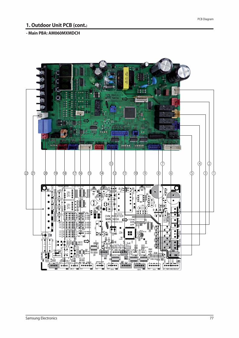
Samsung Electronics 77
PCB Diagram
1. Outdoor Unit PCB (cont.)
- Main PBA: AM060MXMDCH
1
2
3
4
56
7
89101112
13
141516171820 192122
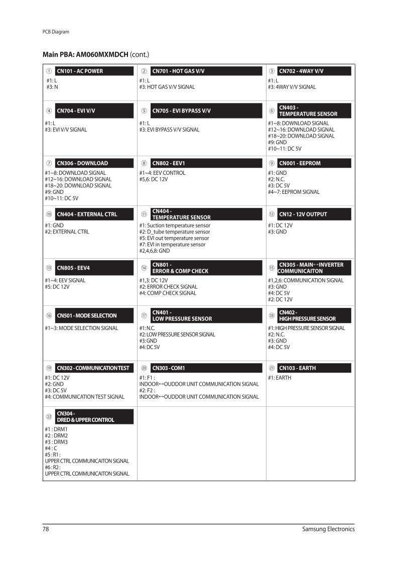
78 Samsung Electronics
PCB Diagram
Main PBA: AM060MXMDCH (cont.)
① CN101 - AC POWER ② CN701 - HOT GAS V/V ③ CN702 - 4WAY V/V
#1: L#3: N
#1: L#3: HOT GAS V/V SIGNAL
#1: L#3: 4WAY V/V SIGNAL
④ CN704 - EVI V/V ⑤ CN705 - EVI BYPASS V/V ⑥ CN403 - TEMPERATURE SENSOR
#1: L#3: EVI V/V SIGNAL
#1: L#3: EVI BYPASS V/V SIGNAL
#1~8: DOWNLOAD SIGNAL#12~16: DOWNLOAD SIGNAL#18~20: DOWNLOAD SIGNAL#9: GND#10~11: DC 5V
⑦ CN306 - DOWNLOAD ⑧ CN802 - EEV1 ⑨ CN001 - EEPROM
#1~8: DOWNLOAD SIGNAL#12~16: DOWNLOAD SIGNAL#18~20: DOWNLOAD SIGNAL#9: GND#10~11: DC 5V
#1~4: EEV CONTROL#5,6: DC 12V
#1: GND#2: N.C.#3: DC 5V#4~7: EEPROM SIGNAL
⑩ CN404 - EXTERNAL CTRL ⑪ CN404 - TEMPERATURE SENSOR
⑫ CN12 - 12V OUTPUT
#1: GND#2: EXTERNAL CTRL
#1: Suction temperature sensor#2: D_tube temperature sensor#5: EVI out temperature sensor#7: EVI in temperature sensor#2,4,6,8: GND
#1: DC 12V#3: GND
⑬ CN805 - EEV4 ⑭ CN801 - ERROR & COMP CHECK
⑮ CN305 - MAIN INVERTER COMMUNICAITON
#1~4: EEV SIGNAL#5: DC 12V
#1,3: DC 12V#2: ERROR CHECK SIGNAL#4: COMP CHECK SIGNAL
#1,2,6: COMMUNICATION SIGNAL#3: GND#4: DC 5V#2: DC 12V
⑯ CN501 - MODE SELECTION ⑰ CN401 - LOW PRESSURE SENSOR
⑱ CN402 - HIGH PRESSURE SENSOR
#1~3: MODE SELECTION SIGNAL #1: N.C.#2: LOW PRESSURE SENSOR SIGNAL#3: GND#4: DC 5V
#1: HIGH PRESSURE SENSOR SIGNAL#2: N.C.#3: GND#4: DC 5V
⑲ CN302 - COMMUNICATION TEST ⑳ CN303 - COM1 ㉑ CN103 - EARTH
#1: DC 12V#2: GND#3: DC 5V#4: COMMUNICATION TEST SIGNAL
#1: F1 : INDOOR OUDDOR UNIT COMMUNICATION SIGNAL#2: F2 : INDOOR OUDDOR UNIT COMMUNICATION SIGNAL
#1: EARTH
㉒ CN304 - DRED & UPPER CONTROL
#1 : DRM1#2 : DRM2#3 : DRM3#4 : C#5 : R1 : UPPER CTRL COMMUNICAITON SIGNAL#6 : R2 : UPPER CTRL COMMUNICAITON SIGNAL
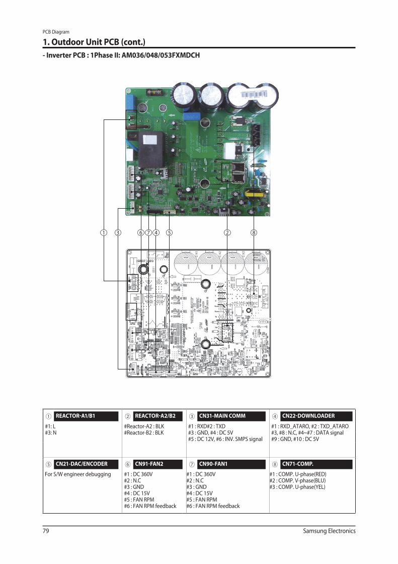
79 Samsung Electronics
PCB Diagram
1. Outdoor Unit PCB (cont.)
- Inverter PCB : 1Phase II: AM036/048/053FXMDCH
1 3 6 7 4 5 2 8
① REACTOR-A1/B1 ② REACTOR-A2/B2 ③ CN31-MAIN COMM ④ CN22-DOWNLOADER
#1: L#3: N
#Reactor-A2 : BLK #Reactor-B2 : BLK
#1 : RXD#2 : TXD #3 : GND, #4 : DC 5V #5 : DC 12V, #6 : INV. SMPS signal
#1 : RXD_ATARO, #2 : TXD_ATARO#3, #8 : N.C, #4~#7 : DATA signal#9 : GND, #10 : DC 5V
⑤ CN21-DAC/ENCODER ⑥ CN91-FAN2 ⑦ CN90-FAN1 ⑧ CN71-COMP.
For S/W engineer debugging #1 : DC 360V #2 : N.C #3 : GND #4 : DC 15V #5 : FAN RPM#6 : FAN RPM feedback
#1 : DC 360V #2 : N.C #3 : GND #4 : DC 15V #5 : FAN RPM #6 : FAN RPM feedback
#1 : COMP. U-phase(RED) #2 : COMP. V-phase(BLU) #3 : COMP. U-phase(YEL)
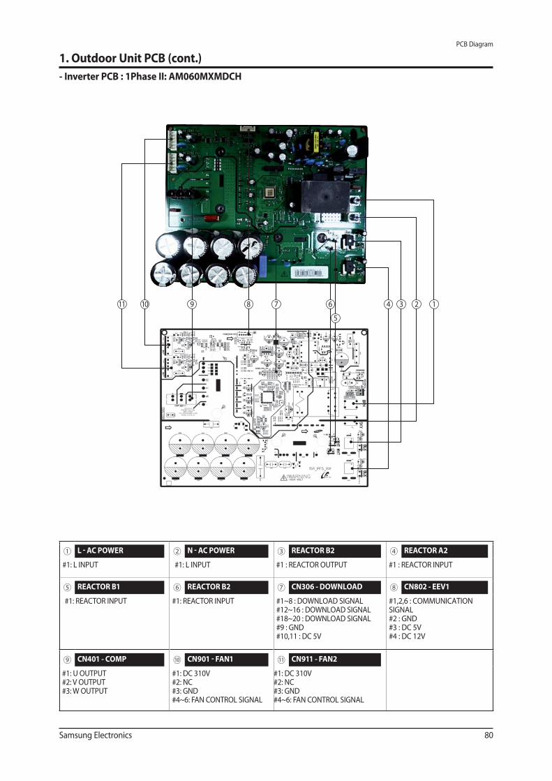
Samsung Electronics 80
PCB Diagram
1. Outdoor Unit PCB (cont.)
- Inverter PCB : 1Phase II: AM060MXMDCH
1234
5
67891011
① L - AC POWER ② N - AC POWER ③ REACTOR B2 ④ REACTOR A2
#1: L INPUT #1: L INPUT #1 : REACTOR OUTPUT #1 : REACTOR INPUT
⑤ REACTOR B1 ⑥ REACTOR B2 ⑦ CN306 - DOWNLOAD ⑧ CN802 - EEV1
#1: REACTOR INPUT #1: REACTOR INPUT #1~8 : DOWNLOAD SIGNAL#12~16 : DOWNLOAD SIGNAL#18~20 : DOWNLOAD SIGNAL#9 : GND#10,11 : DC 5V
#1,2,6 : COMMUNICATION SIGNAL#2 : GND#3 : DC 5V#4 : DC 12V
⑨ CN401 - COMP ⑩ CN901 - FAN1 ⑪ CN911 - FAN2 CN802 - EEV1
#1: U OUTPUT#2: V OUTPUT#3: W OUTPUT
#1: DC 310V#2: NC#3: GND#4~6: FAN CONTROL SIGNAL
#1: DC 310V#2: NC#3: GND#4~6: FAN CONTROL SIGNAL
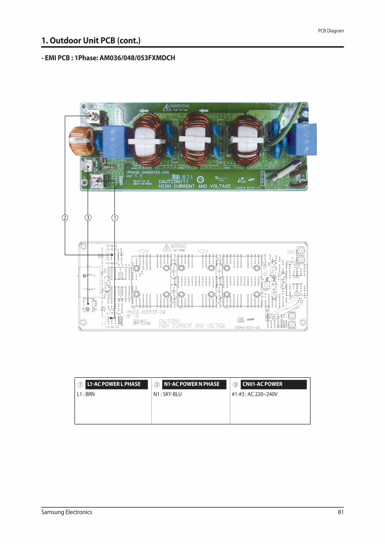
Samsung Electronics 81
PCB Diagram
1. Outdoor Unit PCB (cont.)
- EMI PCB : 1Phase: AM036/048/053FXMDCH
12 3
① L1-AC POWER L PHASE ② N1-AC POWER N PHASE ③ CN01-AC POWER
L1 : BRN N1 : SKY-BLU #1-#3 : AC 220~240V
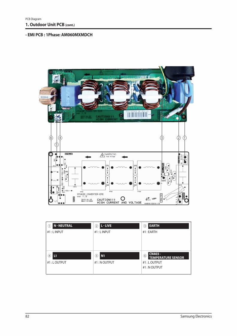
82 Samsung Electronics
PCB Diagram
1. Outdoor Unit PCB (cont.)
- EMI PCB : 1Phase: AM060MXMDCH
1234
5
6
① N - NEUTRAL ② L - LIVE ③ EARTH
#1 : L INPUT #1 : L INPUT #1 : EARTH
④ L1 ⑤ N1 ⑥ CN403 - TEMPERATURE SENSOR
#1 : L OUTPUT #1 : N OUTPUT #1 : L OUTPUT
#1 : N OUTPUT
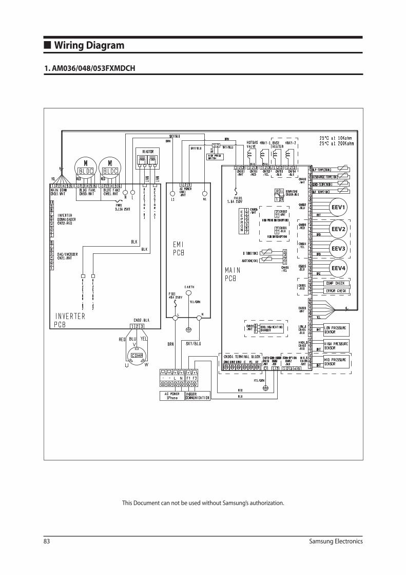
83 Samsung Electronics
■ Wiring Diagram
1. AM036/048/053FXMDCH
This Document can not be used without Samsung’s authorization.
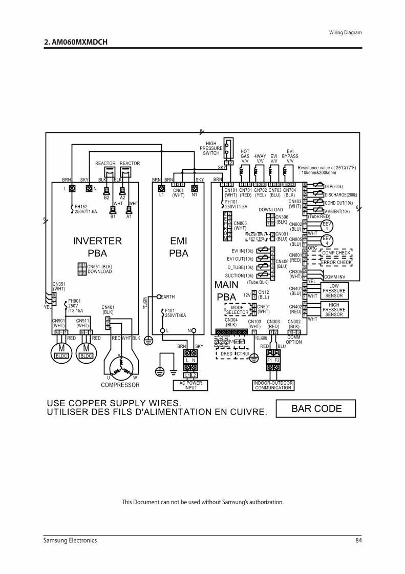
Samsung Electronics 84
Wiring Diagram
2. AM060MXMDCH
This Document can not be used without Samsung’s authorization.
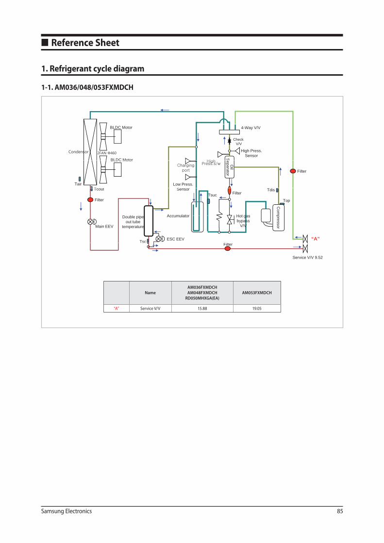
Samsung Electronics 85
1-1. AM036/048/053FXMDCH
■ Reference Sheet
1. Refrigerant cycle diagram
4-Way V/VBLDC Motor
CheckV/V
SHigh Press.
SensorBLDC Motor
Oil
eparator
TairT t
BLDC Motor
Filter
Low Press.S
Com
pHot gas
Tcout Tdis
Filter
Filter
Top
Accumulator
TsucSensor
D bl i
pressor
Hot gasbypass
V/V
ESC EEVTsc
Main EEV
Accumulator
Filt“A”
Double pipeout tube
temperature
Service V/V 9.52
Filter
Name
AM036FXMDCH
AM048FXMDCH
RD050MHXGA(EA)
AM053FXMDCH
“A” Service V/V 15.88 19.05
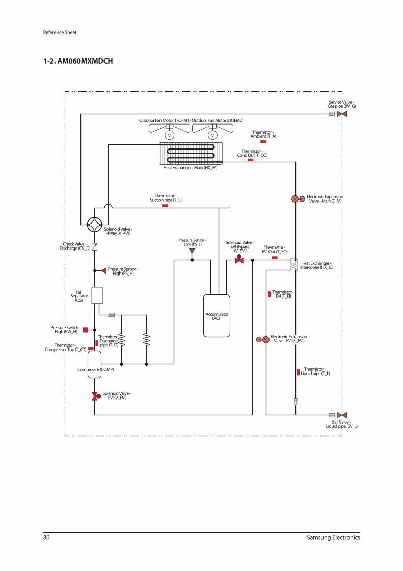
86 Samsung Electronics
Reference Sheet
OilSeparator
(OS)
Accumulator(AC)
Service Valve - Gas pipe (BV_G)
Thermistor - Ambient (T_A)
Outdoor Fan Motor 1 (OFM1) Outdoor Fan Motor 2 (OFM2)
Thermistor - Cond Out (T_CO)
Heat Exchanger - Main (HX_M)
Thermistor - Suction pipe (T_S)
Solenoid Valve - EVI Bypass
(V_EVI)Thermistor -
EVI Out (T_EO)
Heat Exchanger - Intercooler (HX_IC)
Thermistor - Liquid pipe (T_L)
Ball Valve - Liquid pipe (SV_L)
Thermistor - Discharge pipe (T_D)
Solenoid Valve - EVI (V_EVI)
Compressor (COMP)
Thermistor - Compressor Top (T_CT)
Pressure Switch - High (PW_H)
Check Valve - Discharge (CV_D)
Pressure Sensor - High (PS_H)
Solenoid Valve - 4Way (V_4W)
Pressure Sensor - Low (PS_L)
Electronic Expansion Valve - Main (E_M)
Electronic Expansion Valve - EVI (E_EVI)
Thermistor - Evi (T_EI)
1-2. AM060MXMDCH
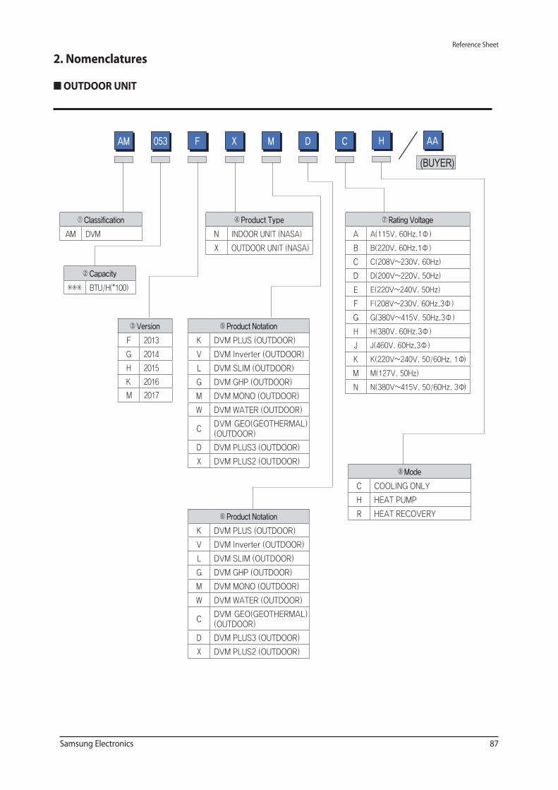
Samsung Electronics 87
Reference Sheet
■ OUTDOOR UNIT
2. Nomenclatures
DM C053AM F X
ClassificationAM DVM
CapacityBTU/H(*100)
VersionF 2013G 2014H 2015
ModeC COOLING ONLYH HEAT PUMPR HEAT RECOVERY
Product TypeN INDOOR UNIT (NASA)X OUTDOOR UNIT (NASA)
Rating VoltageA A(115V, 60Hz,1 Ф )B B(220V, 60Hz,1 Ф )C C(208V~230V, 60Hz)D D(200V~220V, 50Hz)E E(220V~240V, 50Hz)F F(208V~230V, 60Hz,3 Ф )G G(380V~415V, 50Hz,3 Ф )H H(380V, 60Hz,3 Ф )J J(460V, 60Hz,3 Ф )K K(220V~240V, 50/60Hz, 1 Ф)M M(127V, 50Hz)N N(380V~415V, 50/60Hz, 3 Ф)
Product NotationK DVM PLUS (OUTDOOR)V DVM Inverter (OUTDOOR)L DVM SLIM (OUTDOOR)G DVM GHP (OUTDOOR)M DVM MONO (OUTDOOR)W DVM WATER (OUTDOOR)
C DVM GEO(GEOTHERMAL) (OUTDOOR)
D DVM PLUS3 (OUTDOOR)X DVM PLUS2 (OUTDOOR)
H AA
Product NotationK DVM PLUS (OUTDOOR)V DVM Inverter (OUTDOOR)L DVM SLIM (OUTDOOR)G DVM GHP (OUTDOOR)M DVM MONO (OUTDOOR)W DVM WATER (OUTDOOR)
C DVM GEO(GEOTHERMAL) (OUTDOOR)
D DVM PLUS3 (OUTDOOR)X DVM PLUS2 (OUTDOOR)
K 2016M 2017
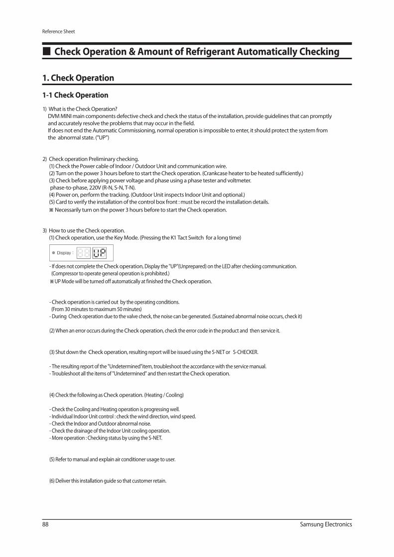
88 Samsung Electronics
Reference Sheet
Check Operation & Amount of Refrigerant Automatically Checking
1. Check Operation
1-1 Check Operation
1) What is the Check Operation?
DVM MINI main components defective check and check the status of the installation, provide guidelines that can promptly
and accurately resolve the problems that may occur in the field.
If does not end the Automatic Commissioning, normal operation is impossible to enter, it should protect the system from
the abnormal state. ("UP")
2) Check operation Preliminary checking.
(1) Check the Power cable of Indoor / Outdoor Unit and communication wire.
(2) Turn on the power 3 hours before to start the Check operation. (Crankcase heater to be heated sufficiently.)
(3) Check before applying power voltage and phase using a phase tester and voltmeter.
phase-to-phase, 220V (R-N, S-N, T-N).
(4) Power on, perform the tracking. (Outdoor Unit inspects Indoor Unit and optional.)
(5) Card to verify the installation of the control box front : must be record the installation details.
※ Necessarily turn on the power 3 hours before to start the Check operation.
3) How to use the Check operation.
(1) Check operation, use the Key Mode. (Pressing the K1 Tact Switch for a long time)
- If does not complete the Check operation, Display the "UP"(Unprepared) on the LED after checking communication.
(Compressor to operate general operation is prohibited.)
※ UP Mode will be turned off automatically at finished the Check operation.
- Check operation is carried out by the operating conditions.
(From 30 minutes to maximum 50 minutes)
- During Check operation due to the valve check, the noise can be generated. (Sustained abnormal noise occurs, check it)
(2) When an error occurs during the Check operation, check the error code in the product and then service it.
(3) Shut down the Check operation, resulting report will be issued using the S-NET or S-CHECKER.
- The resulting report of the "Undetermined"item, troubleshoot the accordance with the service manual.
- Troubleshoot all the items of "Undetermined" and then restart the Check operation.
(4) Check the following as Check operation. (Heating / Cooling)
- Check the Cooling and Heating operation is progressing well.
- Individual Indoor Unit control : check the wind direction, wind speed.
- Check the Indoor and Outdoor abnormal noise.
- Check the drainage of the Indoor Unit cooling operation.
- More operation : Checking status by using the S-NET.
(5) Refer to manual and explain air conditioner usage to user.
(6) Deliver this installation guide so that customer retain.
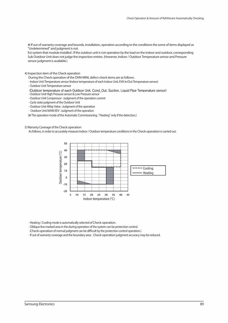
Samsung Electronics 89
Check Operation & Amount of Refriherant Automatically Checking
※ If out of warranty coverage and bounds, installation, operation according to the conditions the some of items displayed as "Undetermined" and judgment is not.
Ex) system that module installed : If the outdoor unit is not operation by the load on the indoor and outdoor, corresponding
Sub Outdoor Unit does not judge the inspection entries. (However, Indoor / Outdoor Temperature sensor and Pressure
sensor judgment is available.)
4) Inspection item of the Check operation
During the Check operation of the DVM MINI, defect check items are as follows.
- Indoor Unit Temperature sensor (Indoor temperature of each Indoor Unit, EVA In/Out Temperature sensor)
- Outdoor Unit Temperature sensor
(Outdoor temperature of each Outdoor Unit, Cond_Out, Suction, Liquid Pipe Temperature sensor) - Outdoor Unit High Pressure sensor & Low Pressure sensor
- Outdoor Unit Compressor : Judgment of the operation current
- Cycle state judgment of the Outdoor Unit
- Outdoor Unit 4Way Valve : Judgment of the operation
- Outdoor Unit MAIN EEV : Judgment of the operation
(※ The operation mode of the Automatic Commissioning : "Heating" only if the detection.)
5) Warranty Coverage of the Check operation
As follows, in order to accurately measure Indoor / Outdoor temperature conditions in the Check operation is carried out.
- Heating / Cooling mode is automatically selected of Check operation.
- Oblique line marked area in the during operation of the system can be protection control.
(Check operation of normal judgment can be difficult by the protection control operation.)
- If out of warranty coverage and the boundary area : Check operation judgment accuracy may be reduced.
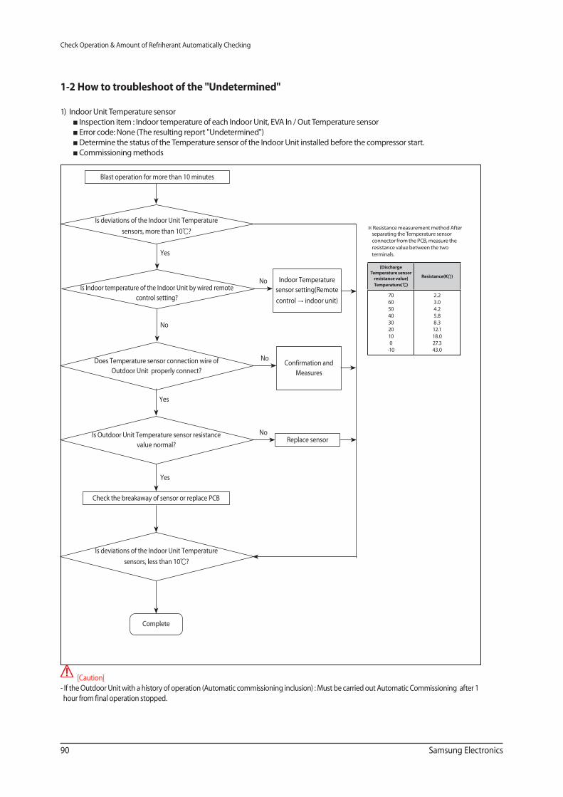
90 Samsung Electronics
Check Operation & Amount of Refriherant Automatically Checking
1-2 How to troubleshoot of the "Undetermined"
1) Indoor Unit Temperature sensor
Inspection item : Indoor temperature of each Indoor Unit, EVA In / Out Temperature sensor
Error code: None (The resulting report "Undetermined")
Determine the status of the Temperature sensor of the Indoor Unit installed before the compressor start.
Commissioning methods
[Caution]
- If the Outdoor Unit with a history of operation (Automatic commissioning inclusion) : Must be carried out Automatic Commissioning after 1
hour from final operation stopped.
Yes
Blast operation for more than 10 minutes
Indoor Temperature
sensor setting(Remote
control → indoor unit)
No
Is deviations of the Indoor Unit Temperature
sensors, more than 10℃?
No
No
Is Indoor temperature of the Indoor Unit by wired remote
control setting?
Check the breakaway of sensor or replace PCB
Does Temperature sensor connection wire of
Outdoor Unit properly connect?
Yes
Is Outdoor Unit Temperature sensor resistance
value normal?
Yes
Is deviations of the Indoor Unit Temperature
sensors, less than 10℃?
Complete
Confirmation and
Measures
NoReplace sensor
※ Resistance measurement method After separating the Temperature sensor
connector from the PCB, measure the
resistance value between the two
terminals.
[Discharge
Temperature sensor
resistance value]
Temperature(℃)Resistance(KΩ)
70
60
50
40
30
20
10
0
-10
2.2
3.0
4.2
5.8
8.3
12.1
18.0
27.3
43.0
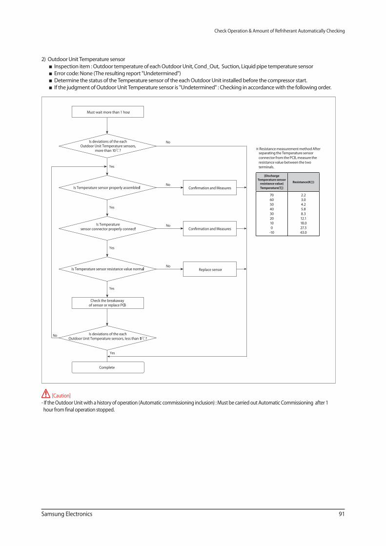
Samsung Electronics 91
Check Operation & Amount of Refriherant Automatically Checking
2) Outdoor Unit Temperature sensor
Inspection item : Outdoor temperature of each Outdoor Unit, Cond_Out, Suction, Liquid pipe temperature sensor
Error code: None (The resulting report "Undetermined")
Determine the status of the Temperature sensor of the each Outdoor Unit installed before the compressor start.
If the judgment of Outdoor Unit Temperature sensor is "Undetermined" : Checking in accordance with the following order.
[Caution]
- If the Outdoor Unit with a history of operation (Automatic commissioning inclusion) : Must be carried out Automatic Commissioning after 1
hour from final operation stopped.
Yes
Yes
NoIs Temperature sensor connector properly connect?
Yes
Replace sensorNo
Is Temperature sensor resistance value normal?
Check the breakaway of sensor or replace PCB
Must wait more than 1 hour
Complete
Is deviations of the each Outdoor Unit Temperature sensors,
more than 10℃?
Is deviations of the each Outdoor Unit Temperature sensors, less than 10℃?
Yes
Yes
No
No
Is Temperature sensor properly assembled?
No
※ Resistance measurement method After separating the Temperature sensor
connector from the PCB, measure the
resistance value between the two
terminals.
[Discharge
Temperature sensor
resistance value]
Temperature(℃)Resistance(KΩ)
70
60
50
40
30
20
10
0
-10
2.2
3.0
4.2
5.8
8.3
12.1
18.0
27.3
43.0
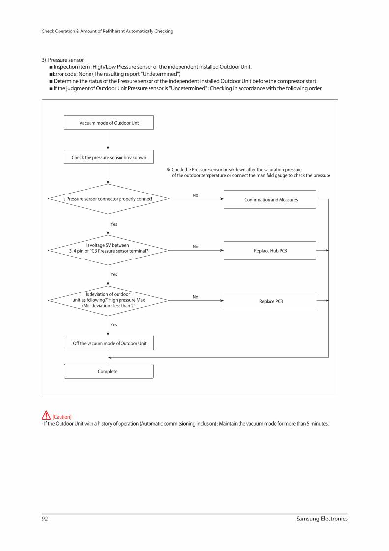
92 Samsung Electronics
Check Operation & Amount of Refriherant Automatically Checking
3) Pressure sensor
Inspection item : High/Low Pressure sensor of the independent installed Outdoor Unit.
Error code: None (The resulting report "Undetermined")
Determine the status of the Pressure sensor of the independent installed Outdoor Unit before the compressor start.
If the judgment of Outdoor Unit Pressure sensor is "Undetermined" : Checking in accordance with the following order.
[Caution]
- If the Outdoor Unit with a history of operation (Automatic commissioning inclusion) : Maintain the vacuum mode for more than 5 minutes.
Yes
NoIs Pressure sensor connector properly connect?
Yes
Replace Hub PCBNoIs voltage 5V between
3, 4 pin of PCB Pressure sensor terminal?
Yes
Replace PCBNo
Is deviation of outdoor unit as following?"High pressure Max
/Min deviation : less than 2"
Check the pressure sensor breakdown
Complete
Vacuum mode of Outdoor Unit
※ Check the Pressure sensor breakdown after the saturation pressure of the outdoor temperature or connect the manifold gauge to check the pressure.
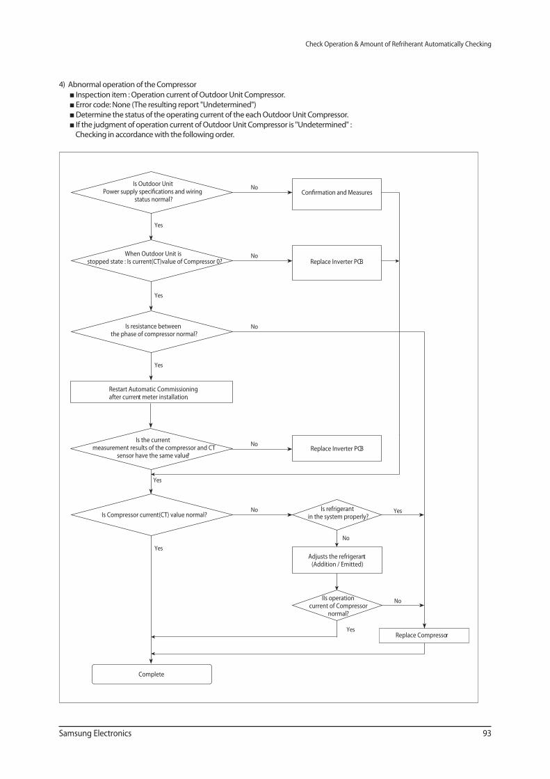
Samsung Electronics 93
Check Operation & Amount of Refriherant Automatically Checking
4) Abnormal operation of the Compressor
Inspection item : Operation current of Outdoor Unit Compressor.
Error code: None (The resulting report "Undetermined")
Determine the status of the operating current of the each Outdoor Unit Compressor.
If the judgment of operation current of Outdoor Unit Compressor is "Undetermined" : Checking in accordance with the following order.
Yes
NoIs Outdoor Unit
status normal?
Yes
Replace Inverter PCBNoWhen Outdoor Unit is
stopped state : Is current(CT)value of Compressor 0?
Yes
NoIs resistance between the phase of compressor normal?
Yes
Is refrigerant in the system properly?
NoIs Compressor current(CT) value normal?
Complete
Replace Inverter PCBNo
Is the current measurement results of the compressor and CT
sensor have the same value?
Yes
Restart Automatic Commissioning after current meter installation.
Yes
No
Yes
No
IIs operation current of Compressor
normal?
Adjusts the refrigerant(Addition / Emitted)
Replace Compressor
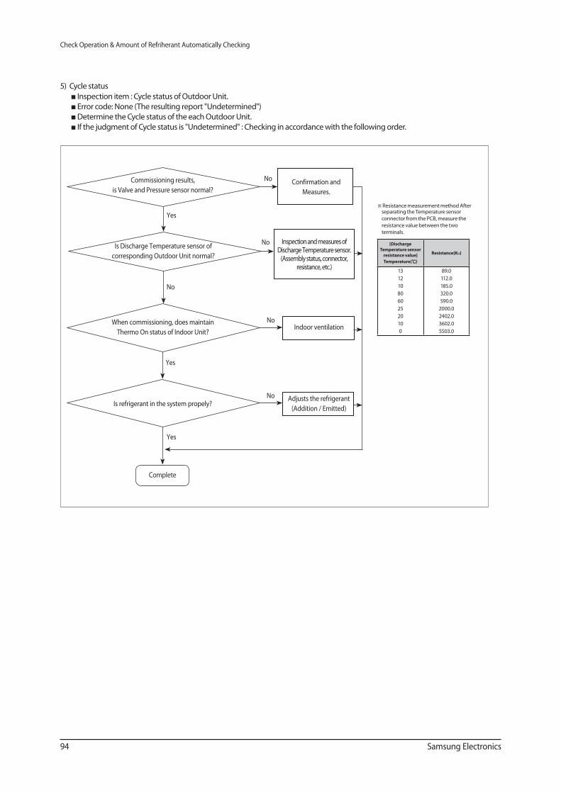
94 Samsung Electronics
Check Operation & Amount of Refriherant Automatically Checking
5) Cycle status
Inspection item : Cycle status of Outdoor Unit.
Error code: None (The resulting report "Undetermined")
Determine the Cycle status of the each Outdoor Unit.
If the judgment of Cycle status is "Undetermined" : Checking in accordance with the following order.
Yes
No
NoCommissioning results,
is Valve and Pressure sensor normal?
No
No
No
Is Discharge Temperature sensor of
corresponding Outdoor Unit normal?
When commissioning, does maintain
Thermo On status of Indoor Unit?
Yes
Is refrigerant in the system propely?
Yes
Complete
[Discharge
Temperature sensor
resistance value]
Temperature(℃)Resistance(Ku)
13
12
10
80
60
25
20
10
0
89.0
112.0
185.0
320.0
590.0
2000.0
2402.0
3602.0
5503.0
※ Resistance measurement method After separating the Temperature sensor
connector from the PCB, measure the
resistance value between the two
terminals.
Inspection and measures of Discharge Temperature sensor.
(Assembly status, connector, resistance, etc.)
Confirmation and
Measures.
Indoor ventilation
Adjusts the refrigerant
(Addition / Emitted)
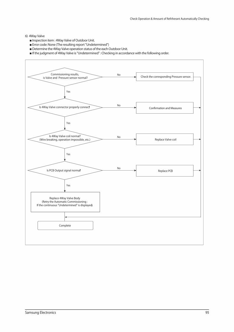
Samsung Electronics 95
Check Operation & Amount of Refriherant Automatically Checking
6) 4Way Valve
Inspection item : 4Way Valve of Outdoor Unit.
Error code: None (The resulting report "Undetermined")
Determine the 4Way Valve operation status of the each Outdoor Unit.
If the judgment of 4Way Valve is "Undetermined" : Checking in accordance with the following order.
Yes
Check the corresponding Pressure sensor.NoCommissioning results,
is Valve and Pressure sensor normal?
Yes
NoIs 4Way Valve connector properly connect?
Yes
Replace Valve coilNoIs 4Way Valve coil normal?
(Wire breaking, operation impossible, etc.)
Yes
Replace PCBNo
Is PCB Output signal normal?
Replace 4Way Valve Body(Retry the Automatic Commissioning :
If the continuous "Undetermined" is displayed.)
Complete
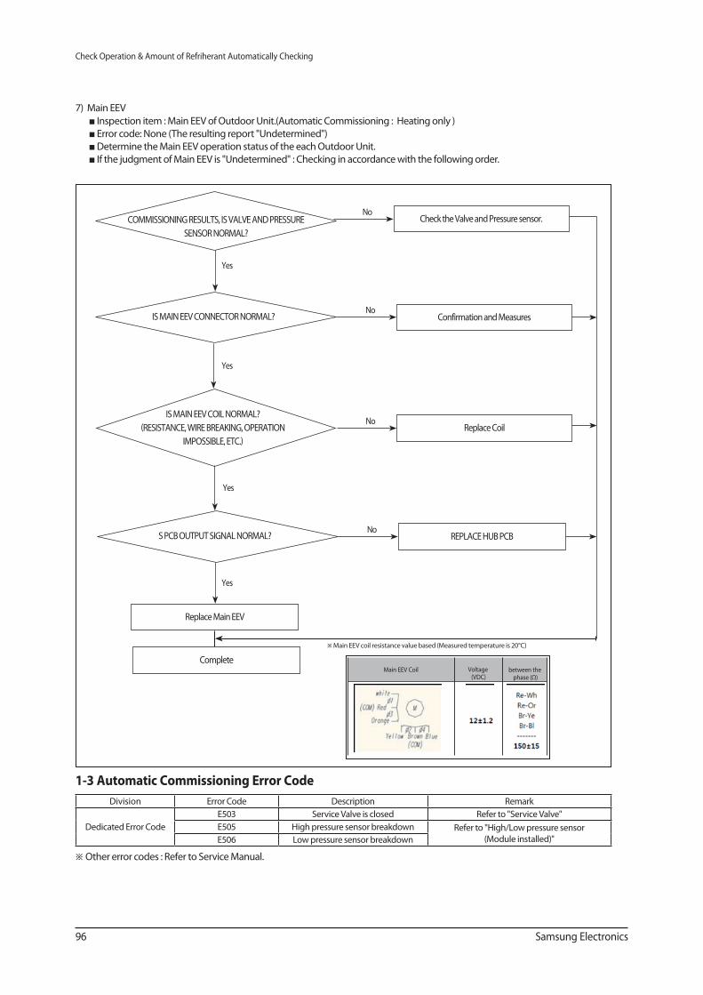
96 Samsung Electronics
Check Operation & Amount of Refriherant Automatically Checking
7) Main EEV
Inspection item : Main EEV of Outdoor Unit.(Automatic Commissioning : Heating only )
Error code: None (The resulting report "Undetermined")
Determine the Main EEV operation status of the each Outdoor Unit.
If the judgment of Main EEV is "Undetermined" : Checking in accordance with the following order.
※ Main EEV coil resistance value based (Measured temperature is 20°C)
Yes
Check the Valve and Pressure sensor.
Yes
NoCOMMISSIONING RESULTS, IS VALVE AND PRESSURE
SENSOR NORMAL?
IS MAIN EEV CONNECTOR NORMAL?
REPLACE HUB PCB
Yes
IS MAIN EEV COIL NORMAL?
(RESISTANCE, WIRE BREAKING, OPERATION
IMPOSSIBLE, ETC.)
S PCB OUTPUT SIGNAL NORMAL?
Replace Main EEV
Complete
Yes
NoConfirmation and Measures
NoReplace Coil
No
Main EEV Coil Voltage (VDC)
between the phase (Ω)
1-3 Automatic Commissioning Error Code
Division Error Code Description Remark
Dedicated Error Code
E503 Service Valve is closed Refer to "Service Valve"
E505 High pressure sensor breakdown Refer to "High/Low pressure sensor
(Module installed)"E506 Low pressure sensor breakdown
※ Other error codes : Refer to Service Manual.
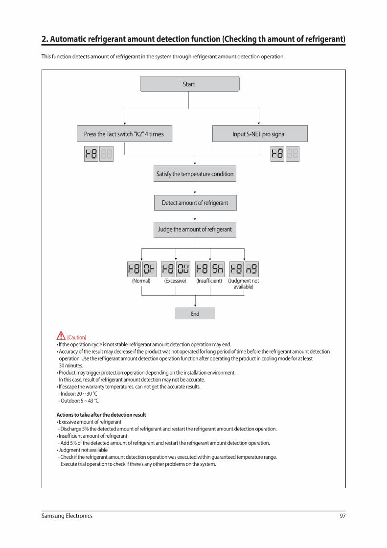
Samsung Electronics 97
2. Automatic refrigerant amount detection function (Checking th amount of refrigerant)
This function detects amount of refrigerant in the system through refrigerant amount detection operation.
[Caution]
operation. Use the refrigerant amount detection operation function after operating the product in cooling mode for at least
30 minutes.
In this case, result of refrigerant amount detection may not be accurate.
- Indoor: 20 ~ 30 °C
- Outdoor: 5 ~ 43 °C
Actions to take after the detection result
- Discharge 5% the detected amount of refrigerant and restart the refrigerant amount detection operation.
- Add 5% of the detected amount of refrigerant and restart the refrigerant amount detection operation.
- Check if the refrigerant amount detection operation was executed within guaranteed temperature range.
Execute trial operation to check if there's any other problems on the system.
Start
Press the Tact switch "K2" 4 times Input S-NET pro signal
Satisfy the temperature condition
Detect amount of refrigerant
Judge the amount of refrigerant
(Judgment notavailable)
(Normal)
End
(Excessive) (Insufficient)
This Service Manual is a property of Samsung Electronics Co., Ltd.
Any unauthorized use of Manual can be punished under applicable
International and/or domestic law.
© Samsung Electronics Co., Ltd. January. 2017.
Printed in Korea. Code No. AC-00013E_2
GSPN (GLOBAL SERVICE PARTNER NETWORK)
Area Web Site
Europe, CIS, Mideast & Africa gspn1.samsungcsportal.com
Asia gspn2.samsungcsportal.com
North & Latin America gspn3.samsungcsportal.com
China china.samsungportal.com