Embed Size (px)
Citation preview

Systec SPhighly dynamic
Technical description

Technical Data Systec SP 160/520
Sumitomo (SHI) Demag Systec SP 160/520
Model description 160/520-430 160/520-600 160/520-840
International size description 1600-430 1600-600 1600-840
Clamp Unit 160/520
Clamp force / Locking force [Ton] 179.81/197.79
Clamp stroke, max. [in] 19.69
Mold height, min. [in] 10.83
Mold height, max. (std./opt.) [in] 23.03/26.97
Open Daylight, max. (std./enl.) [in] 42.72/46.65
Platen size (h x v) [in] 30.31x30.31
Distance between tie bars (h x v) [in] 20.47x20.47
Min. permissible mold diameter (k) [in] 11.81
Max mould weight / mov./ fixed [kg] 2200/1300/1700
Ejection stroke [in] 6.3
Ejection force / Retraction force [Ton] 5.17/2.47
Injection unit 430 600 840
Screw diameter [mm] 35 40 35 40 40 45 40 45 45 50 45 50
Screw geometry standard standard special 1) special 1) standard standard special 1) special 1) standard standard special 1) special 1)
L/D ratio 20 20 25 25 20 20 25 25 20 20 25 25
Spec. injection pressure (up to 400°C) [psi] 38290 29370 38348 29370 35070 27760 35215 27760 34838 28224 34838 28224
Cylinder head volume, max. [in³] 10.8 14.1 10.8 14.1 15.6 19.7 15.6 19.7 21.8 27 21.8 27
Max. shot weight (PS, PE*) [oz] 5.7 7.4 4.5* 6* 8.2 10.4 6.6* 8.3* 11.5 14.2 9.2* 11.4*
Max. rate of injection 2)
> with accumulator [in³/s] 35.8 46.8 35.8 46.8 46.8 59.2 46.8 59.2 53.4 61.1 53.4 61.1
Plastizising rate (PS)
> electric screw drive (PS/PE*) [~oz/s] 1.3/1.13* 1.55/1.34* 1.3/1.13* 1.55/1.34* 1.69/1.48* 1.83/1.66* 1.69/1.48* 1.83/1.66* 1.87/1.69* 2.12/1.76* 1.87/1.69* 2.12/1.76*
Max. screw stroke [in] 7.24 7.99 8.86
Max. distance of nozzle retraction [in] 15.75 15.75 15.75 15.75 15.75 15.75 15.75 15.75 36.02 30
Max. nozzle dipping depth (SVO) [in] 0.79 0.79 0.79 0.79 0.79 0.79 0.79 0.79 0.79 0.79 0.79 0.79
Nozzle contact force [Ton] 8.99 8.99 12.36
Number of heating zones 4 4 4 4 4 4 4 5 5 5 5 5
Hopper capacity, optional [lb] 77 110 154
General data 160/520-430 160/520-600 160/520-840
Oil tank capacity [gal] 106 106 106
Installed electrical rating
> pump [~kW] 36
> electric screw drive [~kW] 27.0 26.7 31.5
> Barrel heating capacity [~kW] 9.4 11.1 13.0 13.9 11.1 11.3 13.9 15.7 13.0 14.8 15.7 22.3
> total capacity [~kW] 72.4 74.1 76.0 76.9 73.8 74.0 76.6 78.4 80.5 82.3 83.2 89.8
Dry cycle time (Euromap 6) [sec-in] 1.3-13.78
Dry cycles with unlocking time [sec-in] 1.5-13.78
Net weight (without oil) 3) [~Ton] 8.27 8.38 8.65
Transport dimensions (l x w x h) [~ft] 18.37x5.25x6.89 18.37x5.25x6.89 18.37x5.25x6.89
Electric drive projection (h) [in] [0]/[0] [0]/[0] [0]/[0] [0]/[0] [0]/[0] 0/0.16 15.98/52.01 22.01/52.01 24.84/52.01 32.52/52.01
The shown specifications reflect the state at the time ofprinting. We reserve the right to modifiy specifications.
Plasticising rate depends on processing conditions andmaterial employed.
Electrical power supply refers to the standard configuration ofthe machine.
These parameters are based on a mains voltage 400 V. Adeviating mains voltage will affect the machine parameters.
1) Shear and mixing unit2) Rate of injection based on the standard plasticizing unit3) The net weight of the machine may vary depending on equipment
2

3
Machine dimensions (l x w x h) Systec SP 160/520
82.2
8
26.5
0
43.3151.18*)
52.9
5
107.87 9.8430.51 min.
a29.53 38.98 35.43 3.94
b
67.8
72.
09-2
.68
c
183.46
27.173.07 30.31 3.07
17.7
2
22.4416.34
26.0
6
12.6
0
57.4
8
212.99
27.1
730
.24
a6.14
34.767.408.746.14IU 600
IU 840
IU 43000
00
65.83
63.9863.98
b gc
78.7
4
option
h see Technical description
Tie Bar Removal
Mould mounting surface (fixed platen)
*) only at enlarged mould height (WA211)
g
1.06
4.0
0 H
8
3.94
6.3
0 H
8
min. 10.83max. 23.03
26.97A B
A B
Z0.79
0.59
optional
15.3
5
13.0
010
.00
7.00
5.00
3.00
5/8"
-11.
UN
C
20.4
723
.62
A - A
23.62
20.47
3.005.00
7.0010.00
13.00
1.57
k
Ø 3
.15
M16 x 32
4.13
1.38
11.0
26.
89
Z Hole pattern for periphery onmovable and fixed platen
)
5.503.50
2.00
30.3
1
B - B28.74 (ZE242)
30.31
20.08
2.003.50
8.00
15 14
38.5825.63
Area reserved for stop bar locationFixed platen
Movable platen
Hole pattern according SPI
k see Technical Descriptionbore diameter ∅ 1.06 through holes
19.69

Technical Data Systec SP 210/580
Sumitomo (SHI) Demag Systec SP 210/580
Model description 210/580-600 210/580-840 210/580-1450
International size description 2100-600 2100-840 2100-1450
Clamp Unit 210/580
Clamp force / Locking force [Ton] 236/259.6
Clamp stroke, max. [in] 22.64
Mold height, min. [in] 13.39
Mold height, max. (std./opt.) [in] 27.17/31.1
Open Daylight, max. (std./enl.) [in] 49.8/53.74
Platen size (h x v) [in] 33.86x33.86
Distance between tie bars (h x v) [in] 22.83x22.83
Min. permissible mold diameter (k) [in] 13.78
Max mould weight / mov./ fixed [kg] 3300/2000/2500
Ejection stroke [in] 7.09
Ejection force / Retraction force [Ton] 8.54/4.16
Injection unit 600 840 1450
Screw diameter [mm] 40 45 40 45 45 50 45 50 50 60 50 60
Screw geometry standard standard special 1) special 1) standard standard special 1) special 1) standard standard special 1) special 1)
L/D ratio 20 20 25 25 20 20 25 25 20 20 25 25
Spec. injection pressure (up to 400°C) [psi] 35070 27760 35215 27760 34838 28224 34838 28224 35186 27630 35172 27630
Cylinder head volume, max. [in³] 15.6 14.2 15.6 19.7 21.8 27 21.8 27 32.3 46.6 32.3 46.6
Max. shot weight (PS, PE*) [oz] 8.2 10.4 6.6* 8.3* 11.5 14.2 9.2* 11.4* 17 24.5 13.6* 19.6*
Max. rate of injection 2)
> with accumulator [in³/s] 46.8 59.2 46.8 59.2 53.4 61.1 53.4 61.1 61.1 77.6 61.1 77.6
Plastizising rate (PS)
> electric screw drive (PS/PE*) [~oz/s] 1.69/1.48* 1.83/1.66* 1.69/1.48* 1.83/1.66* 1.87/1.69* 2.12/1.76* 1.87/1.69* 2.12/1.76* 2.26/1.87* 2.68/2.29* 2.26/1.87* 2.68/2.4*
Max. screw stroke [in] 7.99 7.99 7.99 7.99 8.86 8.86 8.86 8.86 10.63 10.63 10.63 10.63
Max. distance of nozzle retraction [in] 36.02 30 27.17 19.49 36.02 30 27.17 19.49 43.31 31.61 27.17 19.49
Max. nozzle dipping depth (SVO) [in] 0.79 0.79 0.79 0.79 0.79 0.79 0.79 0.79 0.79 0.79 0.79 0.79
Nozzle contact force [Ton] 8.99 12.36 12.36
Number of heating zones 4 4 4 4 5 5 5 5 5 5 5 5
Hopper capacity, optional [lb] 110 154 243
General data 210/580-600 210/580-840 210/580-1450
Oil tank capacity [gal] 106 106 106
Installed electrical rating
> pump [~kW] 51
> electric screw drive [~kW] 26.7 31.5 34.5
> Barrel heating capacity [~kW] 11.1 11.3 13.9 15.7 13.0 14.8 15.7 22.3 14.8 23.1 18.3 27.9
> total capacity [~kW] 88.8 89.0 91.6 93.4 95.5 97.3 98.2 104.8 100.3 108.6 103.8 113.4
Dry cycle time (Euromap 6) [sec-in] 1.4-15.98
Dry cycles with unlocking time [sec-in] 1.6-15.98
Net weight (without oil) 3) [~Ton] 10.14 10.47 10.69
Transport dimensions (l x w x h) [~ft] 19.69x5.58x6.89 19.69x5.58x6.89 19.69x5.58x6.89
Electric drive projection (h) [in] [0]/[0] [0]/[0] 8.11/44.53 14.13/44.53 16.97/44.53 24.61/44.53 21.81/65.12 33.5/65.12 33.5/65.12 45.2/65.12
The shown specifications reflect the state at the time ofprinting. We reserve the right to modifiy specifications.
Plasticising rate depends on processing conditions andmaterial employed.
Electrical power supply refers to the standard configuration ofthe machine.
These parameters are based on a mains voltage 400 V. Adeviating mains voltage will affect the machine parameters.
1) Shear and mixing unit2) Rate of injection based on the standard plasticizing unit3) The net weight of the machine may vary depending on equipment
4

5
Machine dimensions (l x w x h) Systec SP 210/580
82.2
8
26.8
9
43.3151.18*)
54.1
3
124.02 9.8444.02 min.
a35.83 44.88 39.37 3.94
b
g2.
48-3
.07
c
201.18
32.283.07 28.94 3.07
17.1
3
26.3814.96
26.0
6
12.8
0
61.2
6
237.09
28.0
432
.20
78.7
4
67.6
7
79.1
3
a6.14
32.807.4010.126.14IU 840
IU 1450
IU 60000
00
67.01
65.5567.01
b gc
option
h see Technical description
Mould mounting surface (fixed platen)
Tie Bar Removal
*) only at enlarged mould height (WA211)
1.06
4.0
0 H
8
3.94
6.3
0 H
8
min. 13.49max. 27.17
31.100.79
0.59
A B
A B
Z
optional
17.1
3
22.64
15-0
013
.00
10.0
07.
005.
0076
.2
5/8"
- 11
UN
C
22.8
326
.38
A - A
1.57
26.3822.83
3.005.00
7.0010.00
13.0015.00
k
Ø 3
.54
6.89
1.38
13.7
88.
27
Z
M20 X 40
Hole pattern for periphery onmovable and fixed platen
8.00
3.50
3.00
2.00
33.8
6
B - B27.40 30.75(ZE242)
33.86
23.62
2.003.50
8.0014.00
15
40.59
Fixed platenMovable platen
Hole pattern according SPI
k see Technical Description
bore diameter ∅ 1.06 through holesbore diameter ∅ 2.05 through holes+0.04
Area reserved for stop bar location

Technical Data Systec SP 280/630
Sumitomo (SHI) Demag Systec SP 280/630
Model description 280/630-840 280/630-1450 280/630-2300
International size description 2800-840 2800-1450 2800-2300
Clamp Unit 280/630
Clamp force / Locking force [Ton] 314.66/346.13
Clamp stroke, max. [in] 26.57
Mold height, min. [in] 12.99
Mold height, max. (std./opt.) [in] 27.95/32.68
Open Daylight, max. (std./enl.) [in] 54.53/59.25
Platen size (h x v) [in] 36.61x36.61
Distance between tie bars (h x v) [in] 24.8x24.8
Min. permissible mold diameter (k) [in] 15.75
Max mould weight / mov./ fixed [kg] 4300/2500/3300
Ejection stroke [in] 7.87
Ejection force / Retraction force [Ton] 8.54/4.16
Injection unit 840 1450 2300
Screw diameter [mm] 45 50 45 50 50 60 50 60 60 70 60 70
Screw geometry standard standard special 1) special 1) standard standard special 1) special 1) standard standard special 1) special 1)
L/D ratio 20 20 25 25 20 20 25 25 20 20 25 25
Spec. injection pressure (up to 400°C) [psi] 34838 28224 34838 28224 35186 27630 35172 27630 38058 27224 35172 27224
Cylinder head volume, max. [in³] 21.8 27 21.8 27 32.3 46.6 32.3 46.6 54.4 74 54.4 74
Max. shot weight (PS, PE*) [oz] 11.5 14.2 9.2* 11.4* 17 24.5 13.6* 19.6* 28.6 38.9 22.9* 31.2*
Max. rate of injection 2)
> with accumulator [in³/s] 53.4 61.1 53.4 61.1 61.1 77.6 61.1 77.6 77.6 89.2 77.6 89.2
Plastizising rate (PS)
> electric screw drive (PS/PE*) [~oz/s] 1.87/1.69* 2.12/1.76* 1.87/1.69* 2.12/1.76* 2.26/1.87* 2.68/2.29* 2.26/1.87* 2.68/2.4* 2.96/2.54* 3.07/2.61* 2.96/2.65* 3.07/2.79*
Max. screw stroke [in] 8.86 10.63 12.4
Max. nozzle dipping depth (SVO) [in] 0.79 0.79 0.79 0.79 0.79 0.79 0.79 0.79 0.79 0.79 0.79 0.79
Max. distance of nozzle retraction [in] 43.31 31.61 27.17 19.49 43.31 31.61 27.17 19.49 43.31 31.61 27.17 19.49
Nozzle contact force [Ton] 12.36 12.36 12.36
Number of heating zones 5 5 5 5 5 5 5 5 5 5 5 5
Hopper capacity, optional [lb] 154 243 243
General data 280/630-840 280/630-1450 280/630-2300
Oil tank capacity [gal] 145 145 145
Installed electrical rating
> pump [~kW] 51
> electric screw drive [~kW] 31.5 34.5 48.0
> Barrel heating capacity [~kW] 13.0 14.8 15.7 22.3 14.8 23.1 18.3 27.9 23.1 27.0 27.9 32.2
> total capacity [~kW] 95.5 97.3 98.2 104.8 100.3 108.6 103.8 113.4 122.1 126.0 126.9 131.2
Dry cycle time (Euromap 6) [sec-in] 1.65-17.36
Dry cycles with unlocking time [sec-in] 1.95-17.36
Net weight (without oil) 3) [~Ton] 14.55 14.55 15.43
Transport dimensions (l x w x h) [~ft] 21.65x6.23x6.89 21.65x6.23x6.89 22.97x6.23x6.89
Electric drive projection (h) [in] 0/29.57 0/29.57 2.4/29.57 10.08/29.57 7.17/50.55 18.94/49.96 17.64/50.55 30.75/50.55 21.14/66.61 33.11/66.61 32.95/66.61 46.89/66.61
The shown specifications reflect the state at the time ofprinting. We reserve the right to modifiy specifications.
Plasticising rate depends on processing conditions andmaterial employed.
Electrical power supply refers to the standard configuration ofthe machine.
These parameters are based on a mains voltage 400 V. Adeviating mains voltage will affect the machine parameters.
1) Shear and mixing unit2) Rate of injection based on the standard plasticizing unit3) The net weight of the machine may vary depending on equipment
6
7
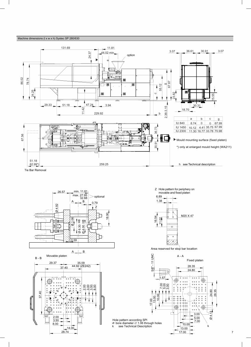
Machine dimensions (l x w x h) Systec SP 280/630
86.0
2
24.2
5
51.1862.99*)
55.1
2
131.69 11.8144.02 min.
a29.33 51.18 47.24 3.94
b
67.8
72.
36-3
.15
c
229.92
30.913.07 36.61 3.07
15.5
5
30.3118.70
23.8
2
11.4
2
67.5
6
259.25
30.9
136
.73
78.7
4
option
h see Technical description
Tie Bar Removal
Mould mounting surface (fixed platen)
*) only at enlarged mould height (WA211)
24.3
7
a8.74
33.7816.7711.3010.12IU 1450
IU 2300
IU 8404.41
035.75
0
70.98
67.9967.99
b gc
g
Z
max. 27.95min. 11.81
0.59
A B
32.680.79A B
Z
optional
18.9
0
Ø 6
.30
H8
Ø 4
.00
H8
Ø 1
.06
Ø 4
.92
16.5
411
.02
6.891.38
M20 X 47
37.4
0
8.00
3.50
3.00
2.00
29.37 35.09B - B
37.40
28.74
2.003.508.00
14.00
44.92 (ZE242)
5/8"
- 11
UN
C17
.00
13.0
010
.00
7.00
5.00
3.00
28.3
524
.80
1.57
A - A
28.3524.80
3.005.00
10.0013.00
7.00
17.00
k
Ø 4
.13
Hole pattern according SPI
k see Technical Descriptionbore diameter ∅ 1.06 through holes
Fixed platenMovable platen
Area reserved for stop bar location
Hole pattern for periphery onmovable and fixed platen26.57

Technical Data Systec SP 350/720
Sumitomo (SHI) Demag Systec SP 350/720-840
Model description 350/720-840 350/720-1450 350/720-2300
International size description 3500-840 3500-1450 3500-2300
Clamp Unit 350/720
Clamp force / Locking force [Ton] 393.33/432.66
Clamp stroke, max. [in] 28.74
Mold height, min. [in] 13.78
Mold height, max. (std./opt.) [in] 29.33/37.4
Open Daylight, max. (std./enl.) [in] 58.07/66.14
Platen size (h x v) [in] 40.94x41.73
Distance between tie bars (h x v) [in] 28.35x28.35
Min. permissible mold diameter (k) [in] 15.75
Max mould weight / mov./ fixed [kg] 4700/2650/3600
Ejection stroke [in] 7.87
Ejection force / Retraction force [Ton] 8.54/4.16
Injection unit 840 1450 2300
Screw diameter [mm] 45 50 45 50 50 60 50 60 60 70 60 70
Screw geometry standard standard special 1) special 1) standard standard special 1) special 1) standard standard special 1) special 1)
L/D ratio 20 20 25 25 20 20 25 25 20 20 25 25
Spec. injection pressure (up to 400°C) [psi] 34838 28224 34838 28224 35186 27630 35172 27630 35186 27224 35172 27224
Cylinder head volume, max. [in³] 21.8 27 21.8 27 32.3 46.6 32.3 46.6 54.4 74 54.4 74
Max. shot weight (PS, PE*) [oz] 11.5 14.2 9.2* 11.4* 17 24.5 13.6* 19.6* 28.6 38.9 22.9* 31.2*
Max. rate of injection 2)
> with accumulator [in³/s] 53.4 61.1 53.4 61.1 61.1 77.6 61.1 77.6 77.6 89.2 77.6 89.2
Plastizising rate (PS)
> electric screw drive (PS/PE*) [~oz/s] 1.87/1.69* 2.12/1.76* 1.87/1.69* 2.12/1.76* 2.26/1.87* 2.68/2.29* 2.26/1.87* 2.68/2.4* 2.96/2.54* 3.07/2.61* 2.96/2.65* 3.07/2.79*
Max. screw stroke [in] 8.86 10.63 12.4
Max. distance of nozzle retraction [in] 36.34 30.28 27.48 19.8 46.65 35 36.18 23.19 45.47 33.5 33.66 19.72
Max. nozzle dipping depth (SVO) [in] 0.79 0.79 0.79 0.79 0.79 0.79 0.79 0.79 0.79 0.79 0.79 0.79
Nozzle contact force [Ton] 12.36 12.36 12.36
Number of heating zones 5 5 5 5 5 5 5 5 5 5 5 5
Hopper capacity, optional [lb] 154 243 243
General data 350/720-840 350/750-1450 350/750-2300
Oil tank capacity [gal] 145 145 145
Installed electrical rating
> pump [~kW] 59
> electric screw drive [~kW] 31.5 34.5 48.0
> Barrel heating capacity [~kW] 13.0 14.8 15.7 22.3 14.8 23.1 18.3 27.9 23.1 27.0 27.9 32.2
> total capacity [~kW] 103.5 105.3 106.2 112.8 108.3 116.6 111.8 121.4 130.1 134.0 134.9 139.2
Dry cycle time (Euromap 6) [sec-in] 1.85-19.84
Dry cycles with unlocking time [sec-in] 2.15-19.84
Net weight (without oil) 3) [~Ton] 17.08 17.64 17.91
Transport dimensions (l x w x h) [~ft] 22.97x6.56x7.55 23.3x6.56x7.55 24.28x6.56x7.55
Electric drive projection (h) [in] 0/29.57 0/29.57 2.4/29.57 10.04/29.57 7.24/53.9 18.94/53.9 17.72/53.9 30.75/53.9 21.14/66.61 33.11/66.61 32.95/66.61 46.89/66.61
The shown specifications reflect the state at the time ofprinting. We reserve the right to modifiy specifications.
Plasticising rate depends on processing conditions andmaterial employed.
Electrical power supply refers to the standard configuration ofthe machine.
These parameters are based on a mains voltage 400 V. Adeviating mains voltage will affect the machine parameters.
1) Shear and mixing unit2) Rate of injection based on the standard plasticizing unit3) The net weight of the machine may vary depending on equipment
8

9
Machine dimensions (l x w x h) Systec SP 350/720
16 15ASSEM 75073265
273.2359.0674.80*)
71.2
6 38.5
032
.68
87.1
3
24.2
578
.74
a
44.02 min.
145.67
26.3
4
14.96
2.36-3.15
g
56.8
9c
b239.76
10.7
1
3.9447.24
21.4
2
59.0633.46
3.0732.683.07 38.98
23.8
2
33.5818.90
15.51
a8.74
35.5517.3211.3010.12IU 1450
IU 2300
IU 8404.880
37.520
72.76
69.7669.76
b gc
67.8
7
option
h see Technical description
Mould mounting surface (fixed platen)
Tie Bar Removal
*) only at enlarged mould height (WA211)
13.7
8
Z
6.891.38
M20 X 40
19.2
9
32.4
8
10.0
07.
005.
00
19.0
05/
8" -
11 U
NC
17.0
013
.00
3.00
28.3
5
A - A
1.57
32.4838.35
3.005.007.00
10.0013.00
17.0019.00
k
Ø 4
.13
41.7
3 8.00
3.50
3.00
2.00
B - B31.14
40.94
31.5014.00
8.00
2.003.50
46.89 (ZE242)
Hole pattern for periphery onmovable and fixed platen
Hole pattern according SPI
k see Technical Descriptionbore diameter ∅ 1.06 through holes
Fixed platenMovable platenArea reserved for stop bar location
1.06
4.00
H8
4.92
6.30
H8
min. 13.78max. 29.33
37.400.79
0.59
A B
A B
Z
optional
20.8
7
28.74
37.05

Technical Data Systec SP 420/820
Sumitomo (SHI) Demag Systec SP 420/820
Model description 420/820-1450 420/820-2300 420/820-3300
International size description 4200-1450 4200-2300 4200-3300
Clamp Unit 420/820
Clamp force / Locking force [Ton] 472/519.2
Clamp stroke, max. [in] 30.31
Mold height, min. [in] 14.96
Mold height, max. (std./opt.) [in] 32.48/41.34
Open Daylight, max. (std./enl.) [in] 62.8/71.65
Platen size (h x v) [in] 47.24x47.24
Distance between tie bars (h x v) [in] 32.28x32.28
Min. permissible mold diameter (k) [in] 16.54
Max mould weight / mov./ fixed [kg] 6600/3800/5100
Ejection stroke [in] 9.06
Ejection force / Retraction force [Ton] 14.38/6.29
Injection unit 1450 2300 3300
Screw diameter [mm] 50 60 50 60 60 70 60 70 70 80 70 80
Screw geometry standard standard special 1) special 1) standard standard special 1) special 1) standard standard special 1) special 1)
L/D ratio 20 20 25 25 20 20 25 25 23 20 25 24
Spec. injection pressure (up to 400°C) [psi] 35186 27630 35172 27630 35186 27224 35172 27224 35143 26905 30458 26905
Cylinder head volume, max. [in³] 32.3 46.6 32.3 46.6 54.4 74 54.4 74 83.1 108.6 83.1 108.6
Max. shot weight (PS, PE*) [oz] 17 24.5 13.6* 19.6* 28.6 38.9 22.9* 31.2* 43.7 57.1 35.1* 45.8*
Max. rate of injection 2)
> with accumulator [in³/s] 61.1 77.6 61.1 77.6 77.6 89.2 77.6 89.2 89.2 98.1 89.2 98.1
Plastizising rate (PS)
> electric screw drive (PS/PE*) [~oz/s] 2.26/1.87* 2.68/2.29* 2.26/1.87* 2.68/2.4* 2.96/2.54* 3.07/2.61* 2.96/2.65* 3.07/2.79* 3.7/3.35* 4.55/4.06* 3.7/3.35* 4.55/4.06*
Max. screw stroke [in] 10.63 12.4 13.94
Max. distance of nozzle retraction [in] 47.44 35.79 36.97 23.98 45.47 33.5 33.66 19.72 38.58 38.58 - -
Max. nozzle dipping depth (SVO) [in] 0.79 0.79 0.79 0.79 0.79 0.79 0.79 0.79 0.79 0.79 0.79 0.79
Nozzle contact force [Ton] 12.36 12.36 12.36
Number of heating zones 5 5 5 5 5 5 5 5 5 5 5 6
General data 420/820-1450 420/820-2300 420/820-3300
Oil tank capacity [gal] 145 145 145
Installed electrical rating
> pump [~kW] 59
> electric screw drive [~kW] 34.5 48.0 76.0
> Barrel heating capacity [~kW] 14.8 23.1 18.3 27.9 23.1 27.0 27.9 32.2 30.6 30.6 32.2 42.6
> total capacity [~kW] 108.3 116.6 111.8 121.4 130.1 134.0 134.9 139.2 165.6 165.6 167.2 177.6
Dry cycle time (Euromap 6) [sec-in] 2.25-22.6
Dry cycles with unlocking time [sec-in] 2.6-22.6
Net weight (without oil) 3) [~Ton] 23.26 23.7 27.45
Transport dimensions (l x w x h) [~ft] 26.25x7.22x7.87 26.25x7.22x7.87 29.86x7.22x7.87
Electric drive projection (h) [in] 0/25.35 0/25.35 0/25.35 1.42/25.35 0/37.28 3.78/37.28 3.62/37.28 17.56/37.28 37.99/76.57 37.64/76.57 51.77/76.57 64.21/76.57
The shown specifications reflect the state at the time ofprinting. We reserve the right to modifiy specifications.
Plasticising rate depends on processing conditions andmaterial employed.
Electrical power supply refers to the standard configuration ofthe machine.
These parameters are based on a mains voltage 400 V. Adeviating mains voltage will affect the machine parameters.
1) Shear and mixing unit2) Rate of injection based on the standard plasticizing unit3) The net weight of the machine may vary depending on equipment
10

11
Machine dimensions (l x w x h) Systec SP 420/820
16 15ASSEM 75073265
a
g
c
b
option
h see Technical description
Mould mounting surface (fixed platen)
Tie Bar Removal
*) only at enlarged mould height (WA211)
2.52-3.8213
.39
19.4
5
29.1
7
85.2
478
.74
22.5
6
15.75179.21
27.95 75.98 47.24 6.30
98.5
4
157.48
286.42
61.4
2
44.02 min.
16.3022.1
3
3.0737.0142.133.07
20.2835.83
42.0
5
79.1
3
37.0
1314.37
74.8094.49*)
a10.12
35.2845.3111.5011.30IU 2300
IU 3300
IU 145000
00
77.2877.28
b g c74.29
1.06
4.0
0 H
8
4.92
6.3
0 H
8
max. 32.4841.34
0.79
0.59
A B
A B
Z
optional
23.8
2
30.31 min. 14.96
13.7
8
Z
6.891.38
M20x40
19.2
9
17.0
013
.00
10.0
07.
005.
00
37.0
132
.28
21.0
0
3.00
3/4"
- 10
UN
C
A - A
1.77
37.0132.28
k
3.005.007.00
10.0013.00
17.0021.00
Ø 4
.72
47.2
4
3.00
3.50
8.00
2.00
5.00
B - B35.67 40.59
47.24
35.04
2.00
20.00
3.508.00
14.00
50.43 (ZE242)
Hole pattern for periphery onmovable and fixed platen
Fixed platenMovable platen Area reserved for stop bar location
Hole pattern according SPI
k see Technical Descriptionbore diameter ∅ 1.06 through holes

Ejector - dimensioned diagram Systec SP
R min = 27.17 N/in²p
2ZY5 r = 0.10 in
+0.02A
-0.0
2
B -0
,5
C -0
.02
D -0.004
E
G
H
M
L
Ejector - connecting dimensions
Machine type Dimensions ( in)
B C HG L MA D E
Coupling zone of ejector rods not hardened
Systec 210/580Systec 160/520
Systec 280/630Systec 350/720Systec 420/820 21.34
19.0917.1314.1711.89
0.35
0.37
0.31 0.791.750.96
1.751.751.75 1.02
1.020.55
1.021.02
1.750.96
1.751.751.75 1.02
1.02
1.021.020.37
0.37
9.06
7.877.096.30
19.4917.5214.5712.20
21.737.87
M16 - 30
M20 - 35M24 - 50
M20 - 35M20 - 35
12

Connection dimensions for material conveyor Systec SP IU 430...600
∅2.76M8-17/22 deep (4x )
1.18
ab
∅ D
dc
A
The injection moulding machine is shown with ZE 320, material hopper
View Y5.51
7.48
Ø 5
.31
Ø 4
.72
A-A
Ø1.77
Systec SP160 - 350
Ddcba
IU 600
IU 430 40
4540
35
6.14
6.14
15.55
15.43
32.56
26.650.790.790.79
0.7934.6838.98
44.0238.98
Injection unit Screwdiameter[mm]
Dimension a [in] with SVO
Dimension[in]
13

Connection dimensions for material conveyor Systec SP IU 840...3300 (up to Systec 420/820)
M8-16 deep (4x )
1.18
a
Detail ”Z”
b
∅ D
Moving platen
Z
View ”A”6.30
∅2.28
∅3.78
60°
60°
6.30
4.72
dc
A
The injection moulding machine is shown with ZE 320, material hopper
IU 84044.02
0.79
48.98 58.62
0.79
IU 145048.98
69.68
0.790.79
58.0781.26
Ddcbaa
IU 3300
IU 2300
70
45
60
50
60
50
80
70
58.07
67.68
77.7677.76
90.83
0.790.790.790.79
10.12
11.50
11.30
8.74 29.21
34.53
35.71
34.33
28.46
32.48
32.48
32.48
Injection unit Screwdiameter[mm]
Dimension a [in] with SVO Dimension [in]Standard barrel
Special barrel
14

Equipment Systec SP 1.600...4.200 kN
15
Clamping unit 160 210 ... 350 420
1 - Short-lengtht units with fully hydraulic clampingsystem with two clamp cylinders and a volumemultipler for fast machine cycles and low energyconsumption - - -2 - Short-lengtht 5-point double toggle clamping unit22 - Ejector coupling to DPG24 - Tie bars of clamping unit chromed27 - Upper tiebar on non-operator side retractable - - -41 - Central ejector with multi-stroke and stroke,pressure/force and speed programmable43 - Short/long stroke ejector47 - Two-stage adjustable clamp force - - -94 - Five-stagedmould clamping- and four-stagedmould-opening sequence204 - Mould mounting dimensions in accordance toEuromap, without side ejector plate205 - Mould mounting dimensions in accordance toEuromap, with side ejector plate207 - Mould mounting dimensions similar to SPI208 - Mould mounting dimensions U (universal; similar to Euromap, additionaly two through-holes) with side ejector plate1) - - -2091 - Mould mounting dimensions similar to JIS210 - Standard mould height211 - Extended mould height215 - Mould and ejector movements only when safetygate closed2171 - Operating when safety gate is open onnon-operator side218 - Ejector pressure and speed programmable forserial operation with mould movement - - -219 - Ejector power and speed programmable forsimultaneous operation with mould movement,including positioning control224ff - 1-2 pneumatik 5/2 directional valves, mountedto moving or fixed platen and freely programmable228 - Central service unit for pneumatic valves229ff - Core puller with 1-4 circuits over proportional oron-/off- valve on mov. platen; Q-independentprogrammable; with unlockable check-valves againstcore-moving; incl. Manual pressure relief forcore-puller 1-4 circuits over one common valve237 - Additional ports for 2 core pullers on fixed mouldplaten 240 - Automatic safety gate on operator side242 - Cover widened on non-operator side243 - Blow through for mould cooling lines; manual249 - Cooling water controller 4 circuits withtemperature gauge250 - Cooling water controller 8 circuits withtemperature gauge244 - Cooling water controller 12 circuits withtemperature gauge252 - Shut-off mould cooling, time programmable282+283 - Pneumatical core puller 1 or 2-circuit viab/w valve on the movable platen including tubing261 - Automatic mould height adjustment18 - Moving platen supported by linear guides onmachine base264 - Manual clamping mechanism for tiebar retraction
Clamping unit 160 210 ... 350 420
265 - Automatic tiebar retraction, upper tiebar onnon-operator side266ff - Hot runner control (number of zones dependingon machine size, max. 32)275 - Hydraulic control for hot runner nozzles280 - Automatic central oil lubrication for toggle290 - Clamp force control with indication293 - ActiveQ: Active mould safety via sensor withmould movement295 - Additional manual adjustable control buttonmould-open-position299 - Central grease lubrication manual
Injection unit 160 210 ... 350 420
Barrel adaptable for 3 injection units - - -92 - Regulated parameter for injection speed,pressure, ram pressure and screw speedprogrammable via profile300 - Injection unit horizontal302ff - Injection unit horizontal or vertical in seperatinglevel or in backpack-position - - -310 - Hydraulic screw motor for high screw speeds(rpm) (motorI) - - -311 - Hydraulic screw motor for high torque (Motor II) - - -313 - Electrical screw motor, frequency-controlled320 - Hopper for setup of an automatic filling system322 - Hopper shutoff with emptying capability (with drillpattern for material conveyor) - - -341 - Temperature of funnel-zone-cooling regulated;maximum temperature 90°C +9°C tolerance350 - Holding pressure switchover depending onhydraulic pressure with maximum value recording andpressure recording 352ff - Holding pressure switchover depending oncavity pressure with pressure recording for 1, 2, 4pressure taker357 - Holding pressure switchover over extern exit355 - Back pressure programmable over screw-backstroke, polygon over 6 stabilisation points361 - fast injection with accumulator; programmable365 - Injection with regular pump, p+v regulated(closed loop) - - -131 - Injection, holding pressure and back pressureregulated over servo valve - - -370 - Melt temperature measuring (only for opennozzles)380 - Nozzle sealing force with closed mould,programmable385 - Nozzle system residual pressure with openmould , programmable386 - Nozzle movement parallel to closing movement388 - Screw position-controlled high speed390 - Full guarding on injection unit operator side - - -
Electronics 160 210 ... 350 420
110 - Supply voltage 400 V+-10 %/ 50 Hz; 3 Ph + N +PE111-117 - Specific national supply voltage
Basic equipment
Additional price
The shown specifications reflect the state at the time ofprinting. We reserve the right to modifiy specifications.
1) valid for CU through 120

16
Electronics 160 210 ... 350 420
120 - Joint power supply for drive and heating - - -121 - Separate power supply for both drive andheating160 - Single-phase 230 V/50 Hz/ 10 A socket inspecific national version, defeatable over main switch1601 - Socket CEE 3Ph/400V/16A, defeatable overmain switch1602 - Socket CEE 3Ph/400V/32A, defeatable overmain switch -161 - Socket combination integrated, country-specific,defeatable over main switch and shut-down program186 - Digital and wearfree stroke measuring systemultrasonic, respectively high-resolution rotary sensorsfor injection and injection unit movement, clamp andejector movement4921 - Integrated mesuring of energy consumption and the costs per piece - - -
Functions 160 210 ... 350 420
420 - Process data entry (PDE) with 100 % monitoringand statistics with graphics for of process parameters421 - Extended intern saving option for PDE-data,mould-records and journal entry422 - Overlay of parameters of consecutive cycles inmultiple graphs on one screen for a convenientevaluation of the process stability424 - Pallet control; uses 2 seperate to orderingprogrammable input/output425 - Storing program for extern storage of statisticdata427 - Temperatur reduction over switchpoint withtiming in manual mode activatable428 - Dry cycle without heat via program switch429 - Preselection part counter forstartup reject partsafter every break of automatic-mode430 - Start up program in 3 stages; including backpressure440 - Switch-on program / switch-off program withpurging442 - switch-on program / switch-off program withoutpurging - - -443 - switch-on program / switch-off program withontime purging - - -445 - Flexible movement sequence for the injectionunit without/with multiple movements from ejector andcore pullers446 - Flexible movement of the injection unit460 - Printer program with automatic printing of errormessage log (alarms, messages and change log)461 - Change reason; on-screen display462 - Event journal471 - factory data capture integrated in machinecontrol480 - Help function; integrated control indication overcontrol481 - Additional operating language485 - Ergostart, integrated basic setting Program - - -486 - Ergosupport: program for faster fault recognitionon basic setting/process optimisation and for extendedmonitoring of process sequence and deviations
Functions 160 210 ... 350 420
488 - Service page489 - Analysis of cycle time493 - Two freely programmable sides494 - Additional two freely programable sides495 - Integration of extern user interfaces in operatorpanel with VNC-client (Active Remote)
Interfaces 160 210 ... 350 420
450 - Inputs / outputs freely programmable; 3 inputsand 3 outputs454 - Inputs / outputs freely programmable; 6 inputsand 6 outputs510 - Socket for second nozzle heater band523 - 50-pin handling device interface conf. toEuromap 67 (VDMA)529 - Interface for handling device, version Asia - - -528 - Adapter cable for Euromap 67 (50-pole) toEuromap 12 (32-pole) and SPI AN-116 (32-pole)532 - Additional controller nozzle 1 circuit540 - Interfaces for ejector limit switch in mould, sideaction with LS and product detection541 - Interface for mould protection (ejector platesafety)542 - Interface for component ejection monitoring544 - Interface for mould safety, side core safetymechanism546 - Interface for screw-back unit555 - Interface for mould temperature indication, 2circuit552 - CAN-Bus interface for temperature controllers (2 or 4 circuits), Demag-specific signal 556 - 20 mA interface (TTY-V24) for up to 6 unitsintegrated temperature controllers562 - Interface machine status563 - Data interface for main computer systems toEuromap 63 and SPI AN-142571 - WC5 - DPG World Connect; Remotemaintenance and control of the machine
General 160 210 ... 350 420
10 - Injection moulding machine with CE-declarationof conformity (without periphery and automation),safety devices according to EN201 USA: machine andsafety devices according to ANSI14 - Oil pre-heating13 - Oil temperatur regulated with temperatur indicator15 - Ports for external oil cleaning17 - Two staged filter control 23 - Clamp force adjustable at Ergocontrol control,including indication of actual valve 50 - Interface for handling device, mechanicalaccording to VDMA 24466/Euromap 1852 - Fault indication: free allocable output - - -67 - DPG-Interface mechanic (drilling pattern) formaterial conveyor71 - USB-Device80 - Interface for extern printer (hardcopy)95 - Machine setup modus (reduced speed)
Basic equipment
Additional price
The shown specifications reflect the state at the time ofprinting. We reserve the right to modifiy specifications.
1) valid for CU through 120

17
General 160 210 ... 350 420
96 - Alarm management (alarms + indications)97 - Setpoint entry switch-over to physical values (bar,cm³, mm/s)98 - Process control105 - Pump driving input I - - -106 - Pump driving input II, increased109 - Pump combination for parallel movement CU - - -122 - Increasement of mashine bed of 100 mm123 - Kill switch on operator side126 - Data display colored135 - Oil cooling (cooling water supply up to 25°C) - - -136 - Oil cooling unit with increased cooling capacity137 - Integrated oil cleaning unit for microfibre bypassfiltration138 - Water supply for mould - and machine-coolingtogether139 - Water supply for mould- and machine-coolingseperated170 - Fault indication by flashing lamp171 - Fault indication by acoustic alarm180 - Anti-vibration mounts705 - QS-switch with control; 2 directions -742 - Connection of the mould cooling up to theclamping plates790 - Integrated printer including driver software802 - ErgoCheck: Dokumentation of machineoperative readiness870 - PC-program for visualisation mould records1092 - Speed-controlled energy saving pump(activeDrive)
Plastification 160 210 ... 350 420
60 - Cylinder change manual61 - Central connector for cylinder heating and thermosensor68 - Operating range of screw cylinder up to 400°C65 - Each temperature control circuit with setpointdeviation control and thermocouple break protection;barrel operating temperatures up to 450°C, withpressure limitation above 400°C (with bi-metal liningbarrel)66 - Fast cylinder change with main plugs für heatingand thermo indicator and with automatic cylinderdetection601 - Energy-saving thermal insulation of theplasticizing610 - Wear and corrosion resistant universalthermoplastic screw, nitrided barrel{\\Operating rangeof screw cylinder up to 400°C}611ff - High-performance plastication unit; customised640 - Flow back barrier (RSP), three-part ring-version642 - Flow back barrier (RSP), ball-version650 - Open nozzle665 - Pneumatic shut off nozzle incl. control
All data and information in this prospectus have been complied with great care. However, we areunable to guarantee its correctness. Furthermore we indicate that individual illustrations andinformation may deviate from the actual delivery condition of the machine.

Notes
18

Notes
19

Practical values of melt correction factor for use in calculation of shot weight for some common plastics.
Material Melt correction factor
HD-PE 0,75
LD-PE 0,73
PP 0,73
PS 0,91
SB 0,91
ABS 0,91
SAN 0,91
PA 0,93
PA 6 +30 % GF 1,14
PC 0,97
PC/ABS 0,94
PMMA 0,97
POM 1,15
PET 1,08
PBT 1,08
CA 1,03
CAB 0,98
PVC-w 1,05
PVC-h 1,15
shot weight = melt correction faktor x swept volume
The melt correction faktor takes into account the change in volume at process tempe-rature and also includes a factor for the flow characteristics of the shut off device on the end of the screw.
Certified according to VDA 6.4
Sumitomo (SHI) Demag Plastics Machinery [email protected]
All data and information provided in this brochure has been compiled and checked with due care and diligence. We believe the contents of this brochure to be accurate, but cannot guarantee its accuracy. The description in this brochure may differ from the machine’s actual condition upon delivery.
Pub
licat
ion
date
: 12/
2013