Embed Size (px)
Citation preview

SysML Workbook – Sparx Enterprise Architect
V1.0.1 – 17 February 2018 Copyright© 2018 i
Twitter: #QAT15SysML
SysML Workbook – Sparx Enterprise Architect
David Hetherington

SysML Workbook – Sparx Enterprise Architect
V1.0.1 – 17 February 2018 Copyright© 2018 ii
Twitter: #QAT15SysML
Table of Contents
Overview of the Space Chessboard System ............................................................. 1
What You Will Need ............................................................................................................ 1
Why is Traceability Important? ................................................ Error! Bookmark not defined.
What is SysML? ........................................................................ Error! Bookmark not defined.
Our Sample System – the Space Chessboard ...................................................................... 2
Step 1 – Creating Your First SysML Model .................................................................. 3
Hello World ........................................................................................................................ 3
Renaming the Model .......................................................................................................... 8
Adding Packages ............................................................................................................... 10
Step 2 – Requirements ............................................................................................... 21
Importing From a CSV File ............................................................................................... 22
Setting Up Your Project File ............................................................................................................22
Understanding CSV files ..................................................................................................................22
Creating a Sparx Import/Export Specification...............................................................................23
Adding Our Requirements to the Template ...................................................................................36
Organize the Requirements ............................................................................................... 40
Making Copies of Requirements ....................................................................................... 41
Creating a Requirements Diagram .................................................................................... 44
Saving a Copy of the Diagram for PowerPoint .................................................................. 49
Clarifying a Single Requirement ........................................................................................ 50
Clarifying Conflicting Requirements ................................................................................. 51
Adding Sub-Requirements ................................................................................................ 52
Step 3 – Modeling the Structure of the System ........................................................ 55
Setting Up Your Project File ............................................................................................................55
System Context .................................................................................................................. 55
Modeling the Basic System - Composition ........................................................................ 59

SysML Workbook – Sparx Enterprise Architect
V1.0.1 – 17 February 2018 Copyright© 2018 iii
Twitter: #QAT15SysML
Aggregation – Game Participants ...................................................................................... 61
Generalization – Types of Pieces and Spaces .................................................................... 62
Step 4 – Elaborating and Allocating Requirements ................................................ 64
Setting Up Your Project File ............................................................................................................65
Chess Pieces and Board – A Closer Look .......................................................................... 66
Finish Up the Initial Clarification ...................................................................................... 66
Clean Up System Structure ................................................................................................ 69
Exporting the Clarified Requirements ............................................................................... 70
Iterative Design and Requirements Allocation .................................................................. 73
The Vodka Detector .........................................................................................................................73
Piece Retention.................................................................................................................................74
Step 5 – Use Cases ..................................................................................................... 78
About Use Cases ................................................................................................................ 78
Make a Use Case Diagram ................................................................................................ 78
Setting Up Your Project File ............................................................................................................78
Create a Use Case Diagram .............................................................................................................79
Allocate Requirements to Use Cases ................................................................................. 81
Step 6 – Interfaces and Sequence Diagrams .......................................................... 83
Interfaces ........................................................................................................................... 83
Setting Up Your Project File ............................................................................................................83
Add an Interface ................................................................................................................ 83
Allocating Requirements to the Interface .......................................................................... 85
Make a Sequence Diagram for the Interface ..................................................................... 86
Step 7 – Test Case ...................................................................................................... 89
Add Test Case to a Requirements Diagram ...................................................................... 89
Setting Up Your Project File ............................................................................................................89
Create a Hierarchical Test Plan for the Piece .................................................................................89
Adding a Child Activity Diagram ...................................................................................... 90

SysML Workbook – Sparx Enterprise Architect
V1.0.1 – 17 February 2018 Copyright© 2018 iv
Twitter: #QAT15SysML

SysML Workbook – Sparx Enterprise Architect
V1.0.1 – 17 February 2018 Copyright© 2018 1
Twitter: #QAT15SysML
Overview of the Space Chessboard System During the next three hours, we are going to do a quick flyover of SysML with a specific tool (Sparx Enterprise Architect in this case) as well as give a brief taste of the idea of a traceable methodology for going from initial requirements all the way to test cases.
Clearly, this short tutorial is NOT going to make you an expert in anything. The goals of this tutorial are simple:
1. Glimpse of Requirements Traceability – for a beginner who is unfamiliar with the topic, this tutorial will provide just enough of an example so that the beginner can imagine the benefits and effort involved.
2. Glimpse of SysML – this tutorial will give beginner a short introduction to Model-Based Systems Engineering (MBSE) and the SysML modeling language.
3. “Start Here” Example for the Tool – SysML is great stuff. Unfortunately, the tools are really complicated. Such tools are usually general-purpose UML tools that have been extended to support dozens of modeling languages. Even though they come with thousands of pages of user documentation, it can be really difficult for even a highly technical user to figure out how to get started and make the “Hello World” SysML model. This tutorial will provide this sort of step-by-step introduction to creating your first model with Sparx Enterprise Architect.
What You Will Need In addition to the tutorial materials, you will need a copy of Sparx Enterprise Architect Systems Engineering Edition. See: http://www.sparxsystems.com/products/ea/systems.html
Note that other less expensive versions of Sparx Enterprise Architect will not include the necessary SysML support to complete this tutorial.

SysML Workbook – Sparx Enterprise Architect
V1.0.1 – 17 February 2018 Copyright© 2018 2
Twitter: #QAT15SysML
Our Sample System – the Space Chessboard
Figure 1 - The Space Chessboard1
Our sample system is the “Space Chessboard” This system is planned for the next long-haul space mission planned to visit the planet Saturn. Since the astronauts will be onboard the spaceship for several years, our space agency has decided that it is important to provide them with some entertainment that will help keep them mentally sharp.
As we dig into the requirements and design of this system, we will find that there are a number of interesting requirements for the system. First of all, we don’t want the pieces to float randomly around the cabin. As such there is a requirement that the chessboard somehow mechanically retain the pieces when the players are not moving them. There is also a design goal that the players be able to play the game while in their bulky spacewalk suits. Finally, the mission psychologist is very interested in monitoring the players as they play to assess stress levels and mental health.
1 Image Source: https://commons.wikimedia.org/wiki/File:Chess_board_with_chess_set_in_opening_position_2012_PD_05.jpg
SysML Workbook – Sparx Enterprise Architect
V1.0.1 – 17 February 2018 Copyright© 2018 3
Twitter: #QAT15SysML
Step 1 – Creating Your First SysML Model
Hello World Start Sparx Enterprise Architect. I usually simply dismiss the start page:
That is, cancel the “Manage Projects” popup and click the “x” to dismiss the start page.

SysML Workbook – Sparx Enterprise Architect
V1.0.1 – 17 February 2018 Copyright© 2018 4
Twitter: #QAT15SysML
Pull down “File” and click “New Project”

SysML Workbook – Sparx Enterprise Architect
V1.0.1 – 17 February 2018 Copyright© 2018 5
Twitter: #QAT15SysML
Navigate to an appropriate directory. Name the project. Click “Save”
The “Model Wizard” Panel should appear. On the “Model Patterns” tab, select “SysML” and “SysML 1.3, Systems Engineering Model” For the purposes of this tutorial, the SysML version is not important. We also will not be working with “Primitive Value Types” or “Quantity Kinds and Units”

SysML Workbook – Sparx Enterprise Architect
V1.0.1 – 17 February 2018 Copyright© 2018 6
Twitter: #QAT15SysML
Your model will now appear. Click the plus sign to expand it.
You will notice that the model has five preinstalled packages. These represent Sparx’s concept of the best way to go about organizing a model. However, actually there is no right or wrong way to organize a model. Highlight the five packages, right click, select “Delete selected items(s)”

SysML Workbook – Sparx Enterprise Architect
V1.0.1 – 17 February 2018 Copyright© 2018 7
Twitter: #QAT15SysML

SysML Workbook – Sparx Enterprise Architect
V1.0.1 – 17 February 2018 Copyright© 2018 8
Twitter: #QAT15SysML
Renaming the Model One of the nice things about SysML is that everything can be named to be easy to understand for your stakeholders. The term “Model” is very generic. Let’s re-name it.
Right click on the word “Model” and select “Rename Model” In the pop-up box, enter “Space Chessboard”
Renaming the Systems Engineering model works a little differently. Right click on it and select “Properties”

SysML Workbook – Sparx Enterprise Architect
V1.0.1 – 17 February 2018 Copyright© 2018 9
Twitter: #QAT15SysML
In the element panel, replace “Systems Engineering Model” with “Requirements and Test Cases Model”
So what is that other thing called “Systems Engineering Model”? That is a pre-configured package diagram that is not going to be helpful for us. Right click on it and delete it.

SysML Workbook – Sparx Enterprise Architect
V1.0.1 – 17 February 2018 Copyright© 2018 10
Twitter: #QAT15SysML
Adding Packages
Now we have an ready-to-go, empty model. Now we can add some packages to it that will actually be useful for us. In doing so, we will demonstrate a few different ways of doing things in the tool.
First lets add an empty diagram.

SysML Workbook – Sparx Enterprise Architect
V1.0.1 – 17 February 2018 Copyright© 2018 11
Twitter: #QAT15SysML
Right click on the model and select “Add Diagram”

SysML Workbook – Sparx Enterprise Architect
V1.0.1 – 17 February 2018 Copyright© 2018 12
Twitter: #QAT15SysML
Select “SysML 1.3” and “Package”
Name the diagram “Model Packages”
Click “OK”
SysML Workbook – Sparx Enterprise Architect
V1.0.1 – 17 February 2018 Copyright© 2018 13
Twitter: #QAT15SysML
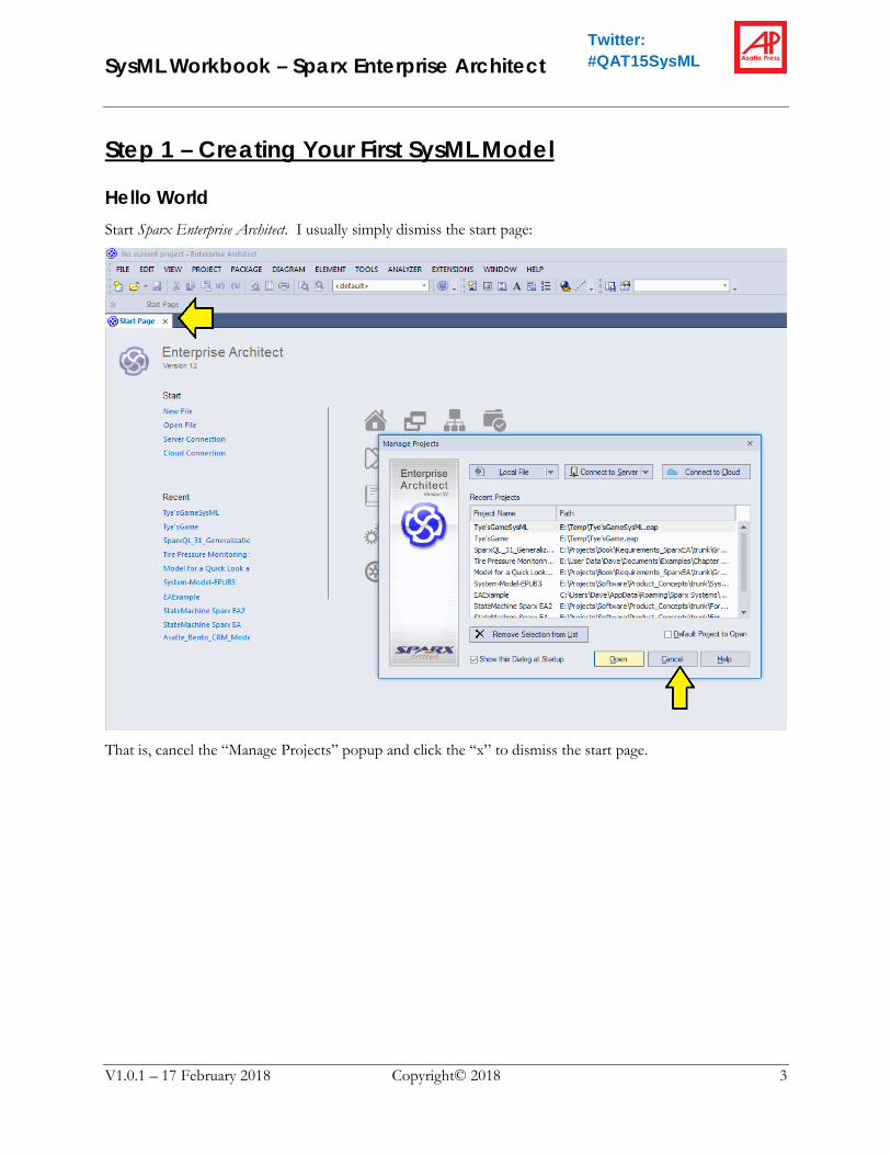
You should now see a new element in the Project Browser called “Model Packages”. You should also see an empty diagram “Model Packages” in the left-hand diagram window. If you do NOT see the diagram, double-click on “Model Packages” in the Project Browser. That should make the empty diagram appear.
Note: unlike some other tools, Sparx Enterprise Architect does NOT display the SysML diagram frame while you are editing. However, it will add the frame once you export the diagram as a graphic file later.
The first thing we will do is drag the top-level model itself (which is also a package) to the diagram. Simply grab the element: “«model» Requirements and Test Cases Model” and drag it onto the diagram. When you let go, a small choice panel will pop up. Choose “Package element”)
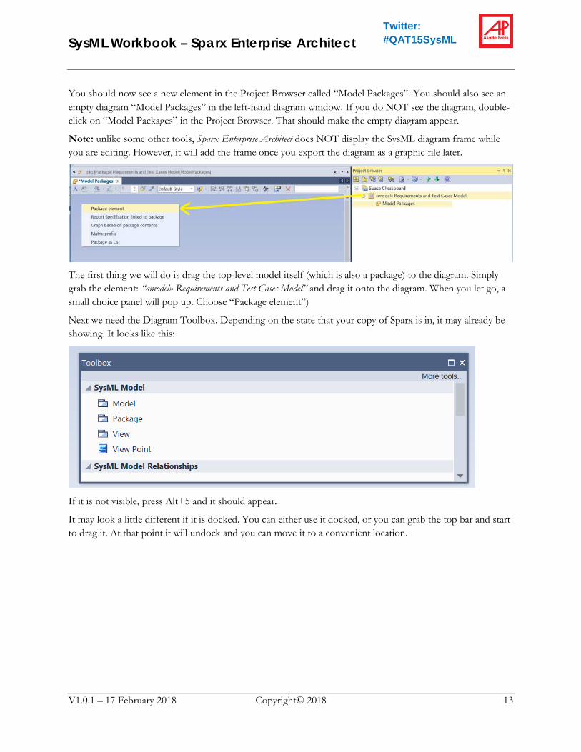
Next we need the Diagram Toolbox. Depending on the state that your copy of Sparx is in, it may already be showing. It looks like this:
If it is not visible, press Alt+5 and it should appear.
It may look a little different if it is docked. You can either use it docked, or you can grab the top bar and start to drag it. At that point it will undock and you can move it to a convenient location.

SysML Workbook – Sparx Enterprise Architect
V1.0.1 – 17 February 2018 Copyright© 2018 14
Twitter: #QAT15SysML
Now we are ready to add a package. Grab the Package element in the Toolbox and drag it onto the diagram as shown. A “New Package” panel will appear.
1. Name the new package “Requirements”
2. Select: “Package Only”
3. Click: OK

SysML Workbook – Sparx Enterprise Architect
V1.0.1 – 17 February 2018 Copyright© 2018 15
Twitter: #QAT15SysML
Next the properties panel will appear. If you like, you can enter a really nice description (complete with fancy fonts) of the Package. Click OK when you are done.
Note: The fancy fonts description is NOT actually part of the SysML standard, but rather a convenient extra feature provided by the tool.
Once we are done, we will see that the “Requirements” Package has ended up in three places:
1. “Requirements” is an element in the diagram
2. In the Project Browser, “Requirements” is shown as part of the model.
3. Back on the diagram, “Requirements” is shown inside the model package, indicating Containment (more on that later)

SysML Workbook – Sparx Enterprise Architect
V1.0.1 – 17 February 2018 Copyright© 2018 16
Twitter: #QAT15SysML
Now we are going to learn something about SysML modeling tools: there are always two ways to add something to the model:
1. Drag something onto a diagram
2. Add it directly from the Project Browser.
Actually, there is a third method and that is to import from a file, but we will get to that a little later on. Next we will practice adding something from the Project Browser.
Right-click on the model and select “Add a Package…” Notice that this menu only appears if you right-click on the model. If you right-click on the “Model Packages” diagram element, you get a different menu.

SysML Workbook – Sparx Enterprise Architect
V1.0.1 – 17 February 2018 Copyright© 2018 17
Twitter: #QAT15SysML
Name the package “Structure”
Notice that the new package shows up in two places (only)
1. In the Project Browser
2. Inside the Model Element in the diagram
A key point is that the new “Structure” package does NOT automatically show up in the diagram. This is a key point of Model-Based Systems Engineering (MBSE):
1. The Model (as shown in the Project Browser) is the “Truth” and contains everything
2. Individual diagrams show only those parts of the model that we think are helpful for one specific stakeholder to understand the model.
Got it. However, we have now decided that our stakeholder for the “Model Packages” diagram does indeed need to see all of the top-level packages in the model when she looks at the “Model Packages” diagram. Go ahead and drag the “Structure” package from the Project Browser into the diagram.

SysML Workbook – Sparx Enterprise Architect
V1.0.1 – 17 February 2018 Copyright© 2018 18
Twitter: #QAT15SysML
Once again, the small panel appears. Select “Package element”
Add three more packages to the model in the same way:
• Use Cases
• Behavior
• Test Cases
Notice that you may have to drag the elements around in the diagram to make them look neat. Just like PowerPoint, the tool has a number of features to align and distribute things.
Now, let’s save a copy of our project.

SysML Workbook – Sparx Enterprise Architect
V1.0.1 – 17 February 2018 Copyright© 2018 19
Twitter: #QAT15SysML
Notice that there is no ordinary “Save” entry. That is because Sparx Enterprise Architect is using the Microsoft JET database engine to manage the file that contains the model data.
Yes. We do want to save the latest information.

SysML Workbook – Sparx Enterprise Architect
V1.0.1 – 17 February 2018 Copyright© 2018 20
Twitter: #QAT15SysML
Now, if you successfully completed Step 1, save the project as shown. This will be the basis for the next step in the tutorial. If you didn’t complete it, no need to worry, there is a copy of “Space Chessboard – Step 1.eap” in the tutorial materials. In this case, you can save your work as “Step 1 – Not Quite Done Yet.eap” or something.
Note: If we actually had a source code control system setup, we would not do all of this file renaming. *.eap files can be managed quite nicely with most source code control systems
SysML Workbook – Sparx Enterprise Architect
V1.0.1 – 17 February 2018 Copyright© 2018 21
Twitter: #QAT15SysML
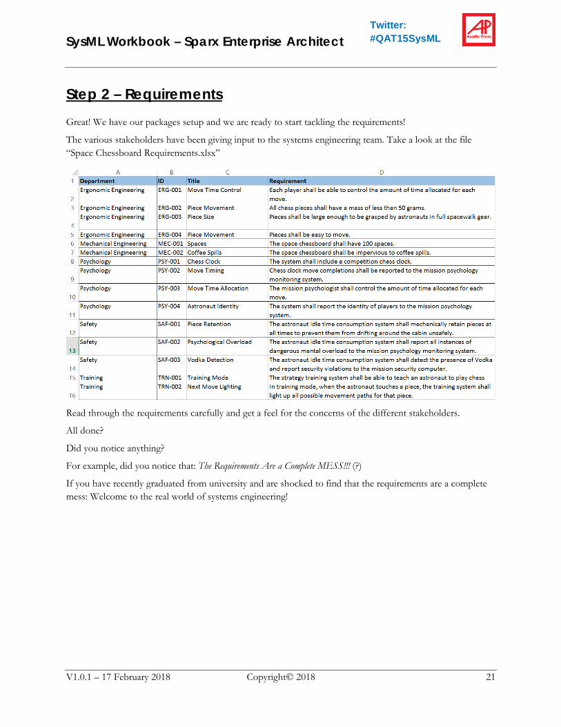
Step 2 – Requirements Great! We have our packages setup and we are ready to start tackling the requirements!
The various stakeholders have been giving input to the systems engineering team. Take a look at the file “Space Chessboard Requirements.xlsx”
Read through the requirements carefully and get a feel for the concerns of the different stakeholders.
All done?
Did you notice anything?
For example, did you notice that: The Requirements Are a Complete MESS!!! (?)
If you have recently graduated from university and are shocked to find that the requirements are a complete mess: Welcome to the real world of systems engineering!

SysML Workbook – Sparx Enterprise Architect
V1.0.1 – 17 February 2018 Copyright© 2018 22
Twitter: #QAT15SysML
Importing From a CSV File OK. The requirements are vague, confusing, contradictory – in short, business as usual for a systems engineering project.
Before we get started, however, I need to comment that getting things in and out of Microsoft Excel is the bane of every SysML tool. On some level, the problem is unsolvable. Spreadsheets are complicated and have random formats. SysML models are also complicated and have a structure that does not really resemble a spreadsheet. The problem is made worse by the fact that SysML is not really a native entity but rather a profile on top of UML, which tends to make the situation even more complicated. Finally, no tool vendor wants to write a dedicated import/export function just for SysML requirements. Instead, they usually write a fully generalized interface for any sort of UML entity to and from any format of spreadsheet…
…and these things are COMPLICATED!!….fasten your seatbelt…
Setting Up Your Project File First, however, let’s make sure you have a clean copy of the results of the Step 1 exercise above.
If you did not fully complete Step 1, copy the file “Space Chessboard - Step 1.eap” from the tutorial materials to your project directory and rename it “Space Chessboard.eap”
Understanding CSV files Sparx Enterprise Architect does not work with standard Excel files, but rather with so-called CSV (comma separated value) files. Above we looked at the file “Space Chessboard Requirements.xlsx” from the tutorial materials. You will notice that there is another file “Space Chessboard Requirements.csv” If you double-click on this file, Microsoft Excel will open it. It will look like the XLSX file except that it will have forgotten all the formatting. The reason there is no formatting is that this is actually a much simpler text format. You can open the CSV file with Notepad or any text editor. It will look like this:
All the information is simple text. Each row is on a separate line. Columns are separated by commas.

SysML Workbook – Sparx Enterprise Architect
V1.0.1 – 17 February 2018 Copyright© 2018 23
Twitter: #QAT15SysML
CSV files are very handy and flexible because they are so simple. However, they do have some vulnerabilities. For example, if your text has commas inside the text, the CSV files will get messy. You can see an example of this problem on the last line of the file above. Even worse are embedded carriage return characters…which can get into your data if you copy–and-paste a block of formatted text into a cell in your Excel spreadsheet.
The easiest way to work with CSV files is usually to keep a master copy of your information in an XLSX file and have Excel export it to CSV just before you need to use it.
Creating a Sparx Import/Export Specification In order to import data from a CSV file, we will need an “Import/Export Specification” The way to make one of these is to add a dummy SysML requirement to our model and export a CSV file containing that one requirement.
Right-click on the “Requirements” package in the Project Browser and select “Add Element”

SysML Workbook – Sparx Enterprise Architect
V1.0.1 – 17 February 2018 Copyright© 2018 24
Twitter: #QAT15SysML
Pull down the “Toolset” selector, scroll down until “SysML 1.3” becomes visible, and select “SysML 1.3 Requirements”
Name the requirement and save.
Now we have a requirement in the system, but it is not really complete yet because the “ID” and “Text” fields have not been set.
(By the way, UML did not really specify a requirements construct. However, the Sparx tools have been around for a long time and Sparx clearly added requirements as a proprietary extension to UML before

SysML Workbook – Sparx Enterprise Architect
V1.0.1 – 17 February 2018 Copyright© 2018 25
Twitter: #QAT15SysML
SysML came into existence. As such, we are going to see a sometimes confusing mix of legacy Sparx-unique requirements functions alongside the SysML requirements functions)
Right-click on the new “Dummy” requirement and select “Properties…”
SysML Workbook – Sparx Enterprise Architect
V1.0.1 – 17 February 2018 Copyright© 2018 26
Twitter: #QAT15SysML
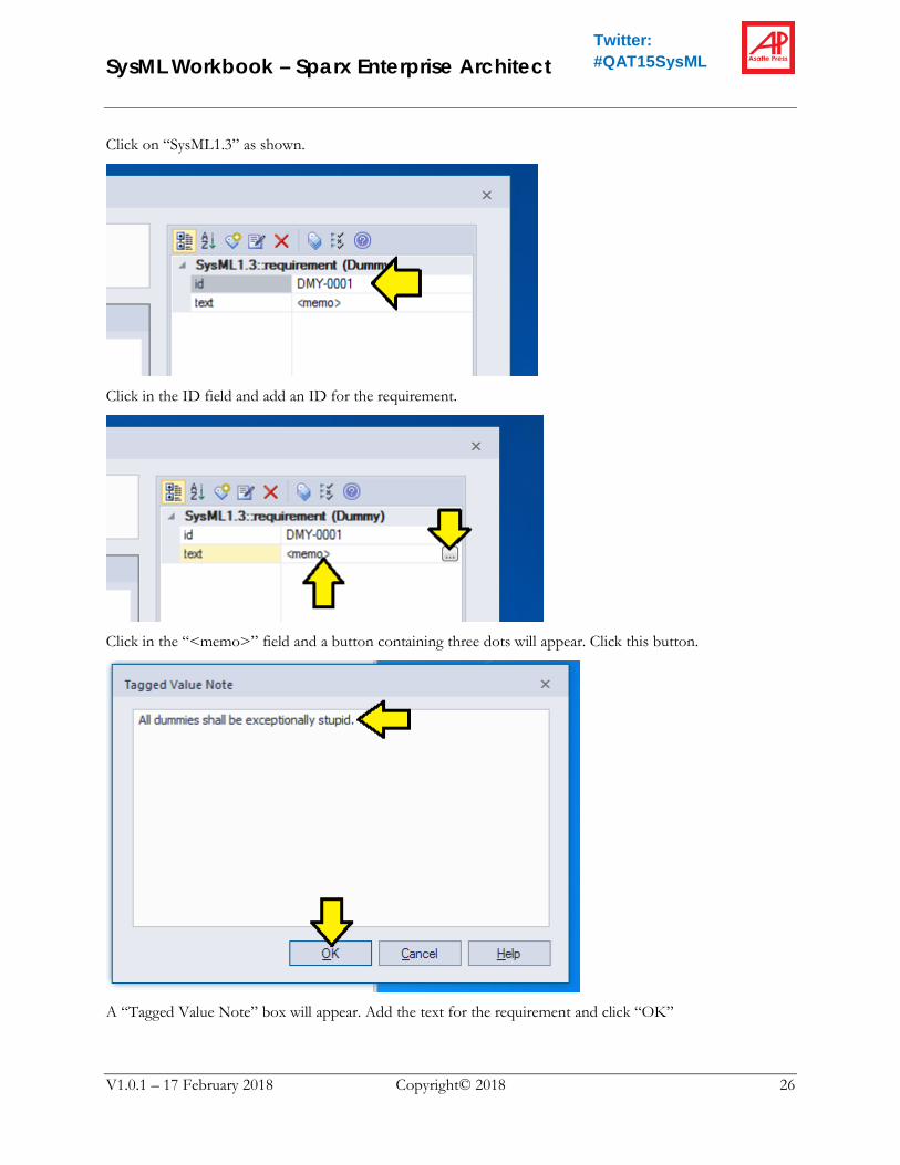
Click on “SysML1.3” as shown.
Click in the ID field and add an ID for the requirement.
Click in the “<memo>” field and a button containing three dots will appear. Click this button.
A “Tagged Value Note” box will appear. Add the text for the requirement and click “OK”

SysML Workbook – Sparx Enterprise Architect
V1.0.1 – 17 February 2018 Copyright© 2018 27
Twitter: #QAT15SysML
Click “OK” to finish defining the requirement.
Great! Now we have a requirement in the model and we have something to export! Now let’s create an export specification.

SysML Workbook – Sparx Enterprise Architect
V1.0.1 – 17 February 2018 Copyright© 2018 28
Twitter: #QAT15SysML
Right click on the “Requirements” package, select “Import/Export” and “CSV Import/Export…”
The first thing we need to do is create a specification for importing and exporting SysML 1.3 requirements. Click “Edit/New…”
Give the specification a sensible name, select comma as the delimiter, and add some Notes.

SysML Workbook – Sparx Enterprise Architect
V1.0.1 – 17 February 2018 Copyright© 2018 29
Twitter: #QAT15SysML
In the “Available Fields” section, select “Name” and click “Add Field” This first field is easy. Every UML element has a “Name” and the SysML 1.3 requirement is no exception. We will certainly need the “names” for all the requirements.
The next one is a little trickier.

SysML Workbook – Sparx Enterprise Architect
V1.0.1 – 17 February 2018 Copyright© 2018 30
Twitter: #QAT15SysML
Pull down the “Add Tagged Value Field” list and select “Value”.
Click “Other Element”

SysML Workbook – Sparx Enterprise Architect
V1.0.1 – 17 February 2018 Copyright© 2018 31
Twitter: #QAT15SysML
Browse down to the Dummy requirement, select it, click “OK”
Select “id” and click OK.

SysML Workbook – Sparx Enterprise Architect
V1.0.1 – 17 February 2018 Copyright© 2018 32
Twitter: #QAT15SysML
Pull down the “Add Tagged Value Field” list and select “Notes”.
Click “Other Element”
SysML Workbook – Sparx Enterprise Architect
V1.0.1 – 17 February 2018 Copyright© 2018 33
Twitter: #QAT15SysML
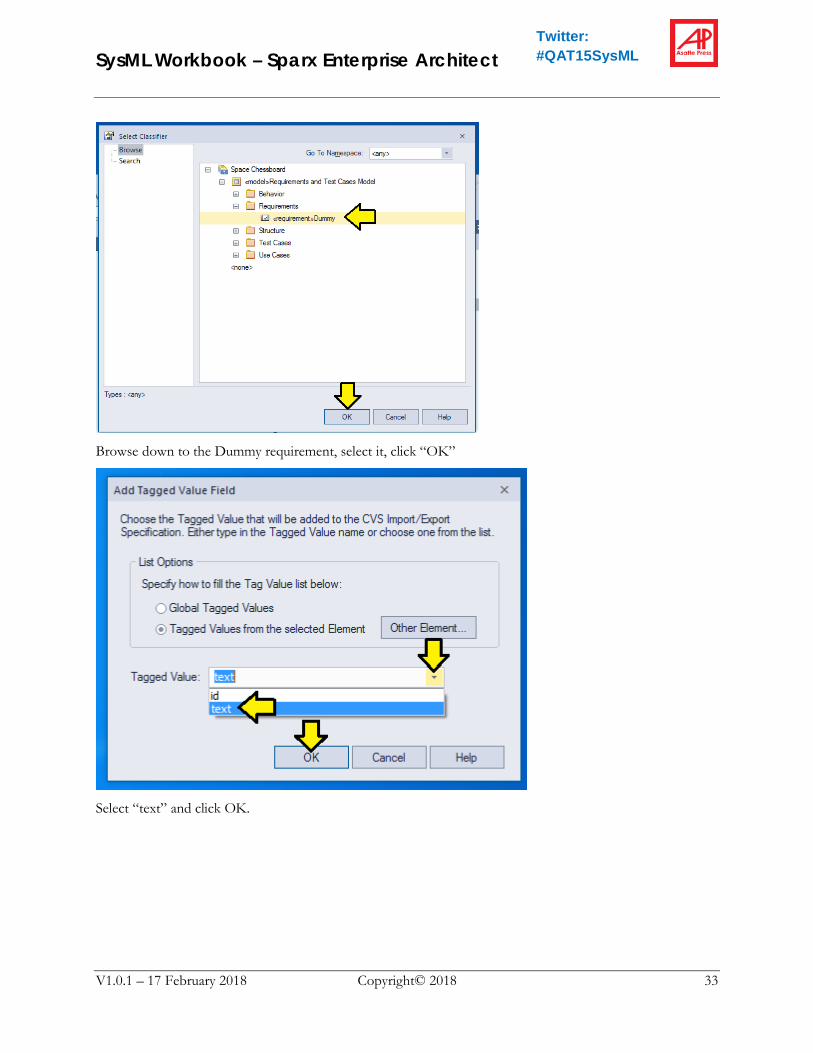
Browse down to the Dummy requirement, select it, click “OK”
Select “text” and click OK.

SysML Workbook – Sparx Enterprise Architect
V1.0.1 – 17 February 2018 Copyright© 2018 34
Twitter: #QAT15SysML
Select “Type” and click “Add Field” We need this field to tell Sparx that we are importing a “requirement” and not some other sort of UML entity.
Scroll down, select “Profile Metatype” and click “Add Field” We need this field to differentiate SysML 1.3 requirements from Sparx proprietary requirements.
Our specification is ready to go. Click “Save” and then “Close”

SysML Workbook – Sparx Enterprise Architect
V1.0.1 – 17 February 2018 Copyright© 2018 35
Twitter: #QAT15SysML
1. Pull down the “Specification” list and select the specification we just created.
2. Click on the three-dots icon and use the file dialog to assign a CSV file name.
3. Click the “Export” radio button
4. Click “Run”
You should get a little status message in the “Results” window. Click “Close” to dismiss the dialog.

SysML Workbook – Sparx Enterprise Architect
V1.0.1 – 17 February 2018 Copyright© 2018 36
Twitter: #QAT15SysML
Adding Our Requirements to the Template In your project directory, you should now have a file “Example_CSV_Export.csv” Double-click on this file to open it in Excel. Adjust the column widths in Excel a little bit and you should have something that looks like this:
What we need to do next is copy our real requirements into this template.
In the tutorial materials, you will find the file “Space Chessboard Requirements.csv” Double-Click to open that file.
1. Copy-and-paste the data from the “ID” column in this spreadsheet to the “TagValue_ID” column in
the export example spreadsheet.
2. Copy-and-paste “Title” to name
3. Copy-and-paste “Requirement” to “TagNotes_text”
4. In the export example spreadsheet, copy the values for the last two columns to all the rows.

SysML Workbook – Sparx Enterprise Architect
V1.0.1 – 17 February 2018 Copyright© 2018 37
Twitter: #QAT15SysML
The finished/merged spreadsheet should look like this.
Save the file as “Requirements_CSV_Import.csv”
Click “Yes” to dismiss the Windows warning.
Exit Excel. This step is important. If you don’t exit Excel, Sparx may think there is a file ownership conflict during the next step.
Now we are ready to import the requirements.

SysML Workbook – Sparx Enterprise Architect
V1.0.1 – 17 February 2018 Copyright© 2018 38
Twitter: #QAT15SysML
Right click on the “Requirements” package, click “Import/Export” and “CSV Import/Export…”

SysML Workbook – Sparx Enterprise Architect
V1.0.1 – 17 February 2018 Copyright© 2018 39
Twitter: #QAT15SysML
1. Pulldown and select the specification.
2. Use the three-dot button to select the file.
3. Click the “Import” radio button.
4. Click “Run”
5. Results will scroll by as each requirement is added.
6. Click “Close” to dismiss the dialog.
Go ahead and clean up the dummy requirement which we will not be needing any more.

SysML Workbook – Sparx Enterprise Architect
V1.0.1 – 17 February 2018 Copyright© 2018 40
Twitter: #QAT15SysML
Organize the Requirements Clearly some of the requirements are going to need to be clarified, extended, and/or rewritten. On the other hand, we don’t want to lose track of the “raw” original requirements as stated by the stakeholders. Let’s separate the requirements into “original” and “clarified” by creating some subpackages.
Right-click on “Requirements” and select “Add a Package…”
Name the package. Also, clicking the “Package Only” radio button will keep the tool from popping up additional confusing menus which we don’t need at this point.
Create an additional subpackage (also in “Requirements”) called “Clarified Requirements”.
SysML Workbook – Sparx Enterprise Architect
V1.0.1 – 17 February 2018 Copyright© 2018 41
Twitter: #QAT15SysML
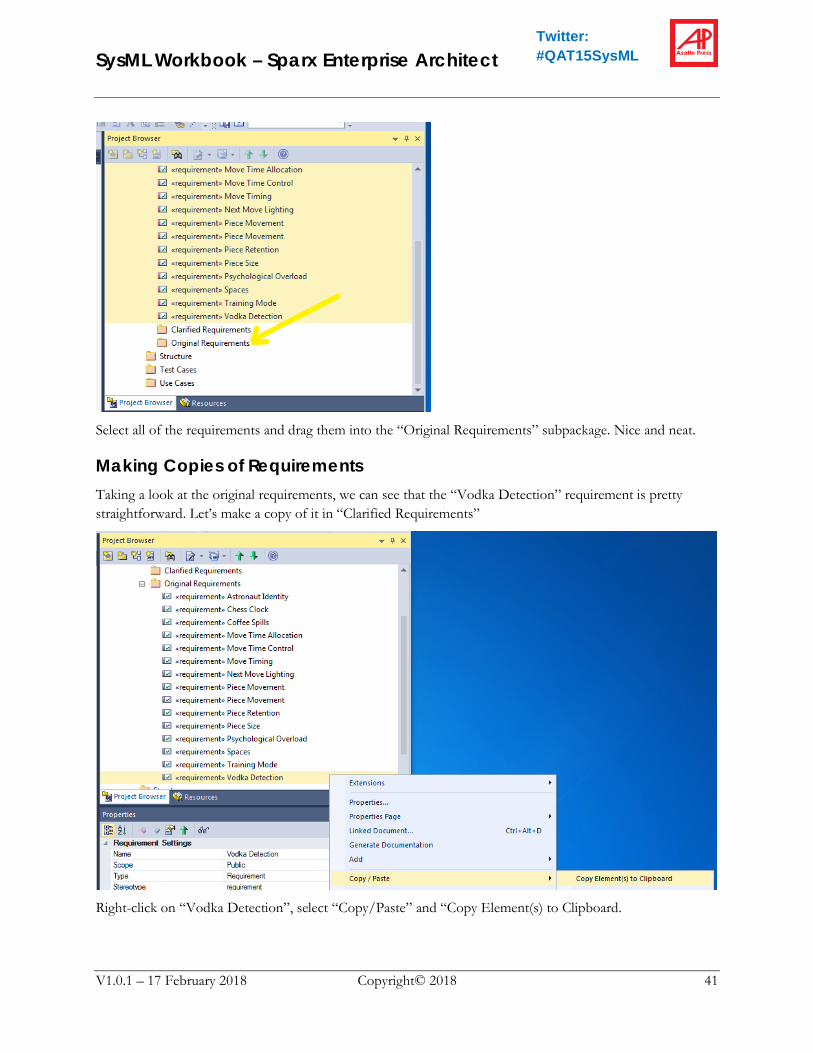
Select all of the requirements and drag them into the “Original Requirements” subpackage. Nice and neat.
Making Copies of Requirements Taking a look at the original requirements, we can see that the “Vodka Detection” requirement is pretty straightforward. Let’s make a copy of it in “Clarified Requirements”
Right-click on “Vodka Detection”, select “Copy/Paste” and “Copy Element(s) to Clipboard.

SysML Workbook – Sparx Enterprise Architect
V1.0.1 – 17 February 2018 Copyright© 2018 42
Twitter: #QAT15SysML
Now, right-click on “Clarified Requirements”, select “Copy/Paste” and “Paste Element(s) from Clipboard”
Voila! Our new requirement is there. However, we will want to clean up two problems with the new requirement:
1. ID – we really do NOT want to who two different requirement elements in the system with the same id. We will need to invent a numbering scheme. Numbering schemes seem like a stupid and trivial problem, but in large organizations they are difficult and critical at the same time! You need to think carefully about your numbering scheme goals (!) Our scheme will work like this:
a. Requirements that are merely copied (like this one) will prepend the number with “CPY-“
b. Requirements that are significantly clarified will prepend the number with “CLR-“
c. Requirements that merge two or more previous will get a new scheme “MRG-00n” where “n” is the number of the merged requirement.
2. Text – our stakeholders have a typical organizational “Tower of Babel” problem. Each team is calling the system something else. We will correct all requirements to call the system “Space Chessboard”
Double-Click on the new copy of “Vodka Detection”
SysML Workbook – Sparx Enterprise Architect
V1.0.1 – 17 February 2018 Copyright© 2018 43
Twitter: #QAT15SysML
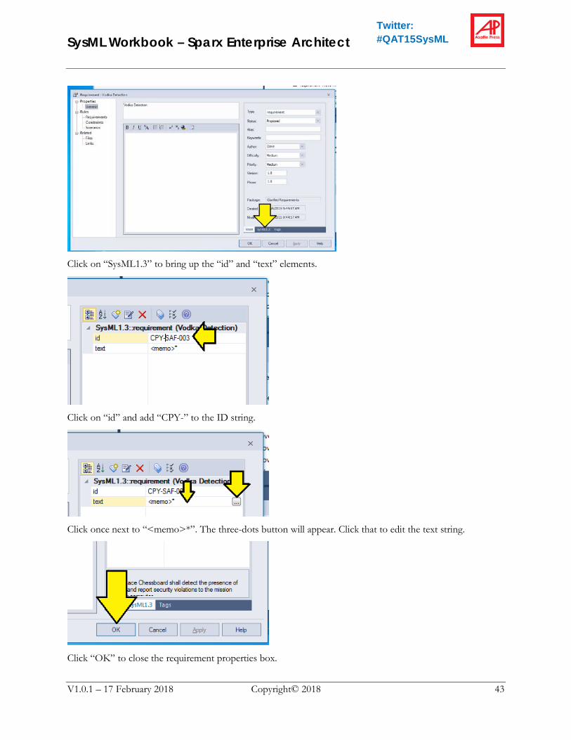
Click on “SysML1.3” to bring up the “id” and “text” elements.
Click on “id” and add “CPY-” to the ID string.
Click once next to “<memo>*”. The three-dots button will appear. Click that to edit the text string.
Click “OK” to close the requirement properties box.

SysML Workbook – Sparx Enterprise Architect
V1.0.1 – 17 February 2018 Copyright© 2018 44
Twitter: #QAT15SysML
Creating a Requirements Diagram OK, we now have a requirement in two versions: an original, and a slightly-corrected (but not substantively changed) version. How are we going to explain that to the Safety department? Those guys can get pretty upset if they think you are ignoring their requirements input! (?)
Model-Based Systems Engineering (MBSE) to the rescue! We can make a diagram, that is coupled to the model just for the Safety department!
Where should we put the diagram? It really doesn’t matter, but I am a “Neat Freak” so I like to make another package just for this purpose. Right-Click on the “Requirements” package and add another subpackage called “Clarification Diagrams”. (See above for the procedure).
Right-click on the new subpackage and select “Add Diagram…”
SysML Workbook – Sparx Enterprise Architect
V1.0.1 – 17 February 2018 Copyright© 2018 45
Twitter: #QAT15SysML
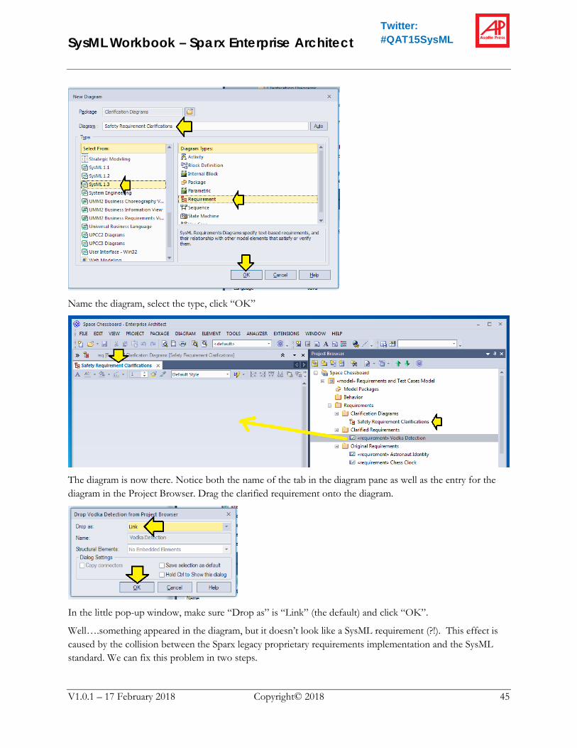
Name the diagram, select the type, click “OK”
The diagram is now there. Notice both the name of the tab in the diagram pane as well as the entry for the diagram in the Project Browser. Drag the clarified requirement onto the diagram.
In the little pop-up window, make sure “Drop as” is “Link” (the default) and click “OK”.
Well….something appeared in the diagram, but it doesn’t look like a SysML requirement (?!). This effect is caused by the collision between the Sparx legacy proprietary requirements implementation and the SysML standard. We can fix this problem in two steps.

SysML Workbook – Sparx Enterprise Architect
V1.0.1 – 17 February 2018 Copyright© 2018 46
Twitter: #QAT15SysML
Select the requirement. Right-Click, select “Advanced”, and select “Use Rectangle Notation”
Next select the requirement again, right-click, select “Features & Properties”, and “Feature and Compartment Visibility…”
Click the radio-button to display “Tags” and click “OK”
Repeat these steps to add the orginal Vodka Detection requirement from the “Original Requirements” subfolder to the diagram.

SysML Workbook – Sparx Enterprise Architect
V1.0.1 – 17 February 2018 Copyright© 2018 47
Twitter: #QAT15SysML
SysML Workbook – Sparx Enterprise Architect
V1.0.1 – 17 February 2018 Copyright© 2018 48
Twitter: #QAT15SysML
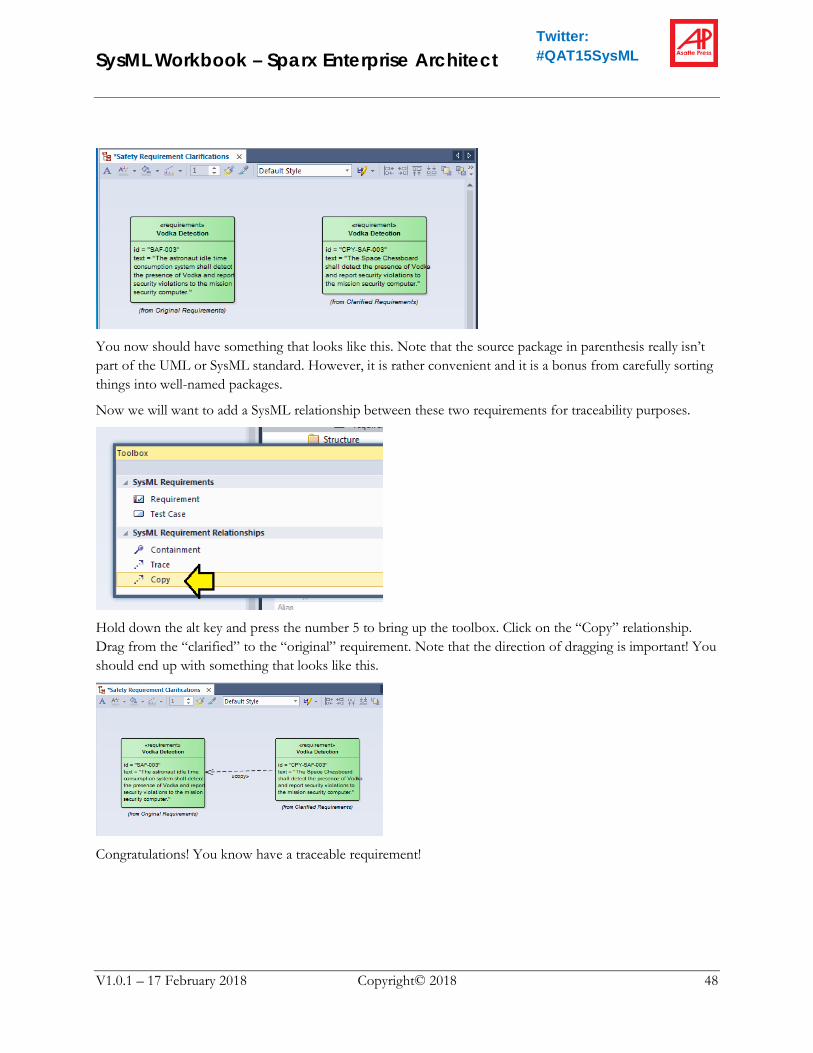
You now should have something that looks like this. Note that the source package in parenthesis really isn’t part of the UML or SysML standard. However, it is rather convenient and it is a bonus from carefully sorting things into well-named packages.
Now we will want to add a SysML relationship between these two requirements for traceability purposes.
Hold down the alt key and press the number 5 to bring up the toolbox. Click on the “Copy” relationship. Drag from the “clarified” to the “original” requirement. Note that the direction of dragging is important! You should end up with something that looks like this.
Congratulations! You know have a traceable requirement!

SysML Workbook – Sparx Enterprise Architect
V1.0.1 – 17 February 2018 Copyright© 2018 49
Twitter: #QAT15SysML
Saving a Copy of the Diagram for PowerPoint Wait! The meeting with the Safety department is in 10 minutes and they are hopping mad because they heard a rumor that you have been ignoring their requirements! Quick, we need to make something for PowerPoint.
The fastest way to do this is to pull down “Diagram” and select “Save Image to Clipboard”. Once you have done that, you can paste the image directly into PowerPoint. The image will look like this:
Notice that the tool has trimmed off the extra whitespace. The tool has also added the diagram frame in compliance with the SysML standard.

SysML Workbook – Sparx Enterprise Architect
V1.0.1 – 17 February 2018 Copyright© 2018 50
Twitter: #QAT15SysML
Clarifying a Single Requirement What if a requirement needs some clarification? The “ERG-004 Piece Movement” requirement is a candidate. What does “easy” mean?! After some discussion with the stakeholders, it is decided that the meaning of easy should be: “Does not require more than 1/20th of a Newton of force to move”.
1. Using the procedure above, copy-and-paste the “ERG-004 Piece Movement” requirement from the “Original Requirements” to the “Clarified Requirements” folder. By the way, notice that the Ergonomics department actually labelled two requirements as “Piece Movement” One of them should really be “Piece Mass”. We should really clean that up by creating a copy as described above. However, for the moment just be sure you copy the right requirement by inspecting the requirement properties in the “Original Requirements” package before you copy it.
2. Edit the properties of the requirement in the “Clarified Requirements” package:
a. Add the “CLR-“ prefix to the ID
b. Change the text of the requirement to “Pieces shall require less than 1/20th of a Newton of force to move.”
3. In the “Clarification Diagrams” package, add a new requirements diagram called: “Ergonomic Requirement Clarifications”
4. Drag original and clarified requirements to the diagram and fixup the format as before.
5. Add a SysML “refine” relationship between them.
While we are at it, let’s deal with that poorly-named second copy of “Piece Movement”. Do the same thing, but rename the clarified requirement “Piece Mass”. In my opinion, renaming the requirement crosses the border between “copy” and “refine” so again use the “refine” relationship. You can add these both to the same diagram.
When you are done, you should have something that looks like this:

SysML Workbook – Sparx Enterprise Architect
V1.0.1 – 17 February 2018 Copyright© 2018 51
Twitter: #QAT15SysML
Clarifying Conflicting Requirements If we look back at the requirements, we can see that ERG-001 and PSY-003 are in direct conflict. The Ergonomics department thinks that the astronauts should be in control of how much time is allocated for each move on the chess clock – after all, what could be less ergonomic than a parameter like that which the user can’t control?! On the other hand, the Mission Psychology department firmly believes that they should be able to control the time – what if the astronauts are slowly losing their marbles? The psychologists definitely feel like they should be able to adjust the move time allocation in order to assess astronaut cognition and stress levels.
After a long debate and some level of management escalation, it is decided that both should be able to control the time-per-move parameter, but that the mission psychologist should have precedence in the event of a conflict.
1. In the “Clarification Diagrams” package, create a new requirements diagram called: “Chess Clock Time-per-Move”
2. Drag both conflicting requirements to the left side of the diagram and fix up the format.
3. From the toolbox, drag a requirement onto the diagram.
4. The properties dialog will pop up. Name the requirement “Move Time Control”
5. In the SysML1.3 tab, set the ID to “MRG-001” and set text to “Mission psychologist and astronaut shall both be able to control the time-per-move with the mission psychologist having precedence.”

SysML Workbook – Sparx Enterprise Architect
V1.0.1 – 17 February 2018 Copyright© 2018 52
Twitter: #QAT15SysML
6. Drag SysML “derive” relationships from the new requirement to both of the original requirements. The result should look like this:
7. Oh…and yes…there is one remaining “Neat Freak” thing to clean up. Since we did not tell it
otherwise, the tool created the new requirement in the diagrams package. Drag the requirement to the clarified requirements package where it belongs.
Adding Sub-Requirements What about requirements that need to contain more detail? We will want to add subrequirements.
Requirement MEC-001 needs some work. First, our mechanical engineers don’t play chess and they have the wrong number of spaces. They also forgot to mention that some spaces are black and some are white.
1. Using the procedure above, copy-and-paste the “MEC-001 Spaces” requirement from the “Original Requirements” to the “Clarified Requirements” folder.
2. Edit the properties of the requirement in the “Clarified Requirements” package:
a. Add the “CLR-“ prefix to the ID
b. Change the text of the requirement to “The space chessboard shall have 64 spaces.”
3. In the “Clarification Diagrams” package, add a new requirements diagram called: “Chessboard Layout”
4. Drag original and clarified requirements to the diagram and fixup the format as before.
5. Add a SysML “refine” relationship between them.

SysML Workbook – Sparx Enterprise Architect
V1.0.1 – 17 February 2018 Copyright© 2018 53
Twitter: #QAT15SysML
6. Drag a requirement to the diagram from the toolbox.
a. Name it “White Spaces”
b. Give it the ID “CLR-MEC-001.a”
c. Give it the text “The Space Chessboard shall have 32 white spaces.”
d. Fix up the SysML format.
7. Add a similar requirement for black spaces with the ID “CLR-MEC-001.b”
8. In the Project Browser, drag the two new requirements from the “Clarification Diagrams” package to the “Clarified Requirements” package.
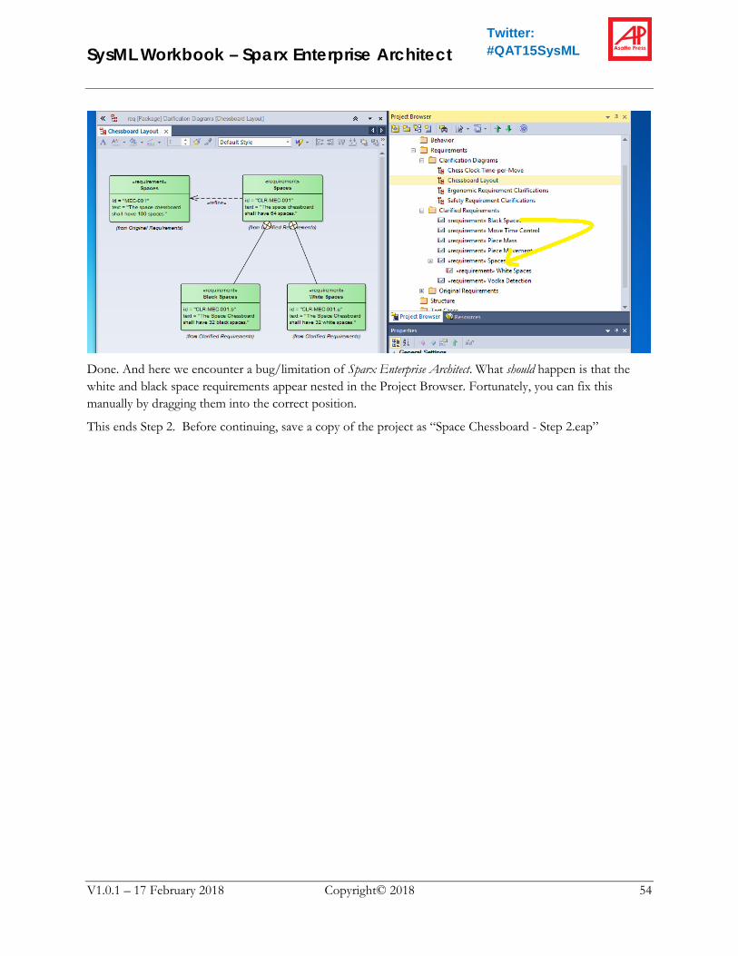
So far, we have something that looks like this. The requirements are there, but they are not coordinated…
1. Press Alt+5 to bring up the toolbox again and select the “containment” relationsip:
2. Drag a containment relationship from the black and white requirements to the “CLR-MEC-001”
requirement.
SysML Workbook – Sparx Enterprise Architect
V1.0.1 – 17 February 2018 Copyright© 2018 54
Twitter: #QAT15SysML
Done. And here we encounter a bug/limitation of Sparx Enterprise Architect. What should happen is that the white and black space requirements appear nested in the Project Browser. Fortunately, you can fix this manually by dragging them into the correct position.
This ends Step 2. Before continuing, save a copy of the project as “Space Chessboard - Step 2.eap”
SysML Workbook – Sparx Enterprise Architect
V1.0.1 – 17 February 2018 Copyright© 2018 55
Twitter: #QAT15SysML
Step 3 – Modeling the Structure of the System In Step 2, we were able to setup some requirements for our system. Next we will start modeling the structure of the system itself.
Setting Up Your Project File Were you able to complete Step 2 above?
If you did not fully complete Step 2, copy the file “Space Chessboard - Step 2.eap” from the tutorial materials to your project directory and rename it “Space Chessboard.eap”
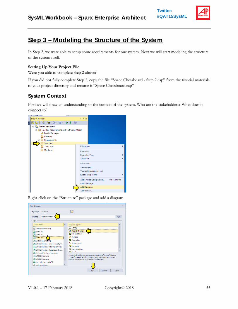
System Context First we will draw an understanding of the context of the system. Who are the stakeholders? What does it connect to?
Right-click on the “Structure” package and add a diagram.

SysML Workbook – Sparx Enterprise Architect
V1.0.1 – 17 February 2018 Copyright© 2018 56
Twitter: #QAT15SysML
Name the diagram “System Context” and make it a Block Definition diagram.
Add an element to the “Structure” package.
1. Name the element “Space Chessboard System”
2. Select the Toolset: “SysML1.3 Block Definition”
3. Select the type: “Block”
4. Click “Save”
5. Drag the new element from the Project Browser to the center of the diagram.
6. Click “OK” to confirm that you want a link.
Next let’s add a boundary around the system. At this point we need to explain that the boundary is not actually part of the SysML specification. However, most system engineers want to add boundaries around elements in this sort of diagram, so most tools (including Sparx Enterprise Architect) provide a feature to do so.
Click on the “New Boundary” icon as shown. Drag to add the boundary.

SysML Workbook – Sparx Enterprise Architect
V1.0.1 – 17 February 2018 Copyright© 2018 57
Twitter: #QAT15SysML
As we can see, a boundary has been added to the diagram. However, nothing in particular has been added to the model in the Project Browser because the boundary is not actually an official SysML element.
Next, add another element to the “Structure” package.
1. Name the element “Astronaut”
2. Toolset is unchanged: “SysML1.3 Block Definition”
3. Select the type: “Actor”
4. Click “Save”
5. Drag the new element from the Project Browser to the upper left part of the diagram.
6. Click “OK” to confirm that you want a link.
Press Alt+5 to make the Toolbox appear. In the SysML Block Relationships area, select the “Reference Association” link type.

SysML Workbook – Sparx Enterprise Architect
V1.0.1 – 17 February 2018 Copyright© 2018 58
Twitter: #QAT15SysML
Drag a reference association from the Astronaut to the Space Chessboard System.
The reference association is the most basic relationship in SysML. It has a flexible and light meaning, but it also serves as the anchor for modeling interfaces later.
Look back at the requirements. Are there any other human stakeholders? Certainly, we can see a mission psychologist. Let’s add the mission psychologist to the model and to the diagram. Hint: copy-paste-rename the Astronaut in the Project Browser and you will save a lot of steps.
How about external systems? Reading the requirements, we can see at least three of these:
1. Mission Psychology System
2. Mission Security System
3. Training System
Let’s add blocks for these and put them on the right side of the diagram.

SysML Workbook – Sparx Enterprise Architect
V1.0.1 – 17 February 2018 Copyright© 2018 59
Twitter: #QAT15SysML
Our System Context diagram is complete for the moment. Why is this diagram important? Experienced systems engineers will always make a diagram like this for two reasons:
1. It identifies things that are NOT part of the system we are trying to design. This point may sound trivial, but in a more complicated system, not having a clear “fence” around your system can lead to big arguments with the stakeholders about what is and what is not in the scope of the project.
2. It identifies interfaces that will need definition.
Modeling the Basic System - Composition Now we are ready to take a closer look at the Space Chessboard System itself. In our first pass of modeling, we discover that the Space Chessboard System consists of:
1. A board
2. A Chess Clock
3. 32 pieces
Let’s model the structure of this.
1. Add another diagram to “Structure” called “Chessboard System Structure”
2. Add blocks to “Structure” for “Board”, “Chess Clock”, and “Piece”
3. Drag the “Space Chessboard System” to the diagram along with these three new blocks.

SysML Workbook – Sparx Enterprise Architect
V1.0.1 – 17 February 2018 Copyright© 2018 60
Twitter: #QAT15SysML
Looks good. Except, why did we use the singular “Piece” when we know that we have 32 “Pieces”? The reason, is we are going to model that relationship explicitly.
If necessary, press Alt+5 to make the Toolbox appear.
Select the Composition relationship…which Sparx Enterprise Architect somewhat confusingly calls “Part Association” Drag the relationship from the “Piece” block to the “Space Chessboard System” block.
1. Double-click on the black diamond relationship.
2. The Aggregation Properties panel will appear.
3. Click on “Role(s)”

SysML Workbook – Sparx Enterprise Architect
V1.0.1 – 17 February 2018 Copyright© 2018 61
Twitter: #QAT15SysML
4. Set the Multiplicity for “Piece” to 32 and the Multiplicity for “Space Chessboard System” to 1.
Add the same composition relationships for the other two blocks and set all multiplicities to 1.
Composition has a meaning along the lines of “consists of” or “is made of”. Here we can see both in the diagram and in the Project Browser that the Space Chessboard System consists of one board, one chess clock, and 32 pieces. This is a strong association. If you instruct your employee to “Discard the Space Chessboard System” you will expect that employee to discard the board, the chess clock, and all 32 pieces.
Aggregation – Game Participants What about the players? They certainly have a role in the system, but discarding the system would not cause the players to cease to exist. This sort of role is “aggregation”.
1. Add an Actor to the Structure called “Player”
2. Drag that actor to the upper left side of the diagram.
3. Select the “aggregation” relationship from the Toolbox (which Sparx Enterprise Architect calls “Shared Association”)
4. Drag an aggregation relationship from the Player to the Space Chessboard System.
5. Set the multiplicity for the Space Chessboard System end to 1 again.
6. Set the multiplicity for the Player end to “0..2” meaning “between 0 and 2 Players”

SysML Workbook – Sparx Enterprise Architect
V1.0.1 – 17 February 2018 Copyright© 2018 62
Twitter: #QAT15SysML
“Aggregation” indicates a sort of reference relationship. Notice that the Player does NOT end up shown as a part inside the Space Chessboard System in the Project Browser.
Generalization – Types of Pieces and Spaces What about pieces? Don’t we want to add more detail? Yes. Generalization will allow us to create more specific types of pieces.
1. Add another Block Definition Diagram to the “Structure” package and name it “Types of Pieces”
2. Drag the “Piece” block onto the diagram.
3. Create blocks for “Pawn”, “Rook”, “Knight”, “Bishop”, “Queen” and “King” and drag them onto the diagram as well.
4. Find the “Generalization” relationship in the Toolbox.
5. Drag a generalization relationship from the Pawn block to the Piece block.
6. Repeat for all the other types of pieces.

SysML Workbook – Sparx Enterprise Architect
V1.0.1 – 17 February 2018 Copyright© 2018 63
Twitter: #QAT15SysML
This relationship is the “is a kind of” relationship. That is: “Knight is a kind of Piece”
(Note that in UML Land, they speak a different sort of language which can be a bit obtuse for normal humans. UMLians will generally say something like: “Piece generalizes Knight”)
Make a similar diagram called “Types of Spaces” to show black and white spaces as the specific spaces of the more general space.
This ends Step 3. Before continuing, save a copy of the project as “Space Chessboard - Step 3.eap”

SysML Workbook – Sparx Enterprise Architect
V1.0.1 – 17 February 2018 Copyright© 2018 64
Twitter: #QAT15SysML
Step 4 – Elaborating and Allocating Requirements One thing missing from most SysML textbooks is a strategy for elaborating and allocating requirements for different levels of the system. Requirements engineering textbooks, on the other hand, recommend something like this: “Keep refining and elaborating until you have requirements that require exactly one thing that can be satisfied by exactly one unique component” These are called “Leaf Requirements”.
Putting those two ideas together, you might imagine something like this:
This is sort of acceptable, but we can see two things from this diagram:
1. Parallel Activity – elaboration of the requirements is going to have to proceed in parallel/coordination with elaboration of the system design. This is definitely going to be a “throw it over the wall” waterfall-style activity.
2. Accountability – Using this sort of approach, you don’t make any formal connection between the requirements and the system until you get to the bottom -> The very end of the process!
3. Overview – What about that “Sandwich Eating Subsystem”? There is no way to get an overview of the requirements that its modules are responsible for.
Well, item (1) is simply a fact. As for (2) and (3) we can solve these problems by using the Hetherington method, which looks like this:

SysML Workbook – Sparx Enterprise Architect
V1.0.1 – 17 February 2018 Copyright© 2018 65
Twitter: #QAT15SysML
“Allocate” is a more flexible relationship than “Satisfy”. In this manner, the requirements team can work in parallel with the system design team, gradually refining both the requirements and design while maintaining continuous synchronization between the two streams.
That is, the deeper you go into the system design, the fewer “allocate” and the more “satisfy” relationships you will encounter.
Setting Up Your Project File Were you able to complete Step 3 above?
If you did not fully complete Step 3, copy the file “Space Chessboard - Step 3.eap” from the tutorial materials to your project directory and rename it “Space Chessboard.eap”

SysML Workbook – Sparx Enterprise Architect
V1.0.1 – 17 February 2018 Copyright© 2018 66
Twitter: #QAT15SysML
Chess Pieces and Board – A Closer Look Let’s take a closer look at the chess pieces and the chess board.
A quick inspection of the original requirements reveals several that are definitely going to affect the design of the board and the pieces. We have already clarified a few of these. Let’s finish up the initial clarification.
Finish Up the Initial Clarification Let’s see, we already clarified ERG-002 and ERG-004. Let’s take care of ERG-003. A simple copy should be sufficient.
1. Copy-and-Paste ERG-003 from “Original Requirements” to “Clarified Requirements”
2. Change the ID of the new requirement to “CPY-ERG-003”
3. Open the diagram: “Ergonomic Requirement Clarifications”
4. Add both the original and the copy to this diagram.
Department ID Title RequirementErgonomic Engineering ERG-002 Piece Movement All chess pieces shall have a mass of less than 50 grams.Ergonomic Engineering ERG-003 Piece Size Pieces shall be large enough to be grasped by astronauts in full spacewalk
gear.Ergonomic Engineering ERG-004 Piece Movement Pieces shall be easy to move.Mechanical Engineering MEC-001 Spaces The space chessboard shall have 100 spaces.Mechanical Engineering MEC-002 Coffee Spills The space chessboard shall be impervious to coffee spills.Safety SAF-001 Piece Retention The astronaut idle time consumption system shall mechanically retain
pieces at all times to prevent them from drifting around the cabin Training TRN-002 Next Move Lighting In training mode, when the astronaut touches a piece, the training system
shall light up all possible movement paths for that piece.

SysML Workbook – Sparx Enterprise Architect
V1.0.1 – 17 February 2018 Copyright© 2018 67
Twitter: #QAT15SysML
5. Add a SysML “Copy” relationship from the clarified to the original requirement.
Let’s see, MEC-001 was already clarified. Let’s make copies of MEC-002 and SAF-001 and add them to the diagram “Safety Requirement Clarifications”

SysML Workbook – Sparx Enterprise Architect
V1.0.1 – 17 February 2018 Copyright© 2018 68
Twitter: #QAT15SysML
Create a new requirements diagram called “Training Clarifications” and make a copy TRN-002.
Great! Now we have a complete set of clarified requirements…at least for the next task…and we can turn our attention to the system structure.

SysML Workbook – Sparx Enterprise Architect
V1.0.1 – 17 February 2018 Copyright© 2018 69
Twitter: #QAT15SysML
Clean Up System Structure If we now look at the “Structure” package in the Project Browser, we can see that it is getting a little messy. Let’s clean it up a little.
1. Create a subpackage called “Top-Level Structure Diagrams”
2. Move the diagrams “System Context” and “Chessboard System Structure” into this subpackage.
3. Create a subpackage called “Actors” and move the three actors into that subpackage.
4. Create a subpackage called “Board” and move the diagram “Chessboard Spaces” as well as the blocks “Board”, “Space”, “Black Space”, and “White Space” into that subpackage.
5. Create a subpackage called “External Systems” and move the three external systems into that subpackage.
6. Create a subpackage called “Clock” and move the block “Chess Clock” into that subpackage
7. Create a subpackage called “Pieces” and move the diagram “Types of Pieces” as well as all the pieces block into that.
8. The cleaned up “Structure” package should look like this:
9. Collapse and expand each subpackage. Does everything seem to be in the right place? If not, move
items around as needed.

SysML Workbook – Sparx Enterprise Architect
V1.0.1 – 17 February 2018 Copyright© 2018 70
Twitter: #QAT15SysML
Exporting the Clarified Requirements At this point, it would be handy to have a fresh copy of the clarified requirements. Fortunately, it is now quite easy to export these to a CSV file and open them in Excel.
Right-click on the “Clarified Requirements” folder, select “Export/Import” and “CSV Import/Export…”
1. Select the same “Specification” that we created before
2. Browse to select/create a filename
3. Select “Export”
4. Click “Run”
SysML Workbook – Sparx Enterprise Architect
V1.0.1 – 17 February 2018 Copyright© 2018 71
Twitter: #QAT15SysML
5. Click “Close”

SysML Workbook – Sparx Enterprise Architect
V1.0.1 – 17 February 2018 Copyright© 2018 72
Twitter: #QAT15SysML
We can now open that file in Excel by clicking on it.
Hmmm… doesn’t look like much. However, if we pretty up the format a little and save it as an Excel file, it will look much better.
Name TagValue_id TagNotes_text Type Profile Metatype
Vodka Detection CPY-SAF-003The Space Chessboard shall detect the presence of Vodka and report security violations to the mission security computer.
Requirement SysML1.3::Requirement
Piece Movement CLR-ERG-004 Pieces shall require less than 1/20th of a Newton of force to move. Requirement SysML1.3::Requirement
Piece Mass CLR-ERG-002 All chess pieces shall have a mass of less than 50 grams. Requirement SysML1.3::Requirement
Move Time Control MRG-001Mission psychologist and astronaut shall both be able to control the time-per-move with the mission psychologist having precedence.
Requirement SysML1.3::Requirement
Spaces CLR-MEC-001 The space chessboard shall have 64 spaces. Requirement SysML1.3::Requirement
White Spaces CLR-MEC-001.a The Space Chessboard shall have 32 white spaces. Requirement SysML1.3::Requirement
Black Spaces CLR-MEC-001.b The Space Chessboard shall have 32 black spaces. Requirement SysML1.3::Requirement
Piece Size CPY-ERG-003 Pieces shall be large enough to be grasped by astronauts in full spacewalk gear. Requirement SysML1.3::Requirement
Coffee Spills CPY-MEC-002 The Space Chessboard shall be impervious to coffee spills. Requirement SysML1.3::Requirement
Piece Retention CPY-SAF-001The Space Chessboard shall mechanically retain pieces at all times to prevent them from drifting around the cabin unsafely.
Requirement SysML1.3::Requirement
Training Mode CPY-TRN-001 The strategy training system shall be able to teach an astronaut to play chess Requirement SysML1.3::Requirement

SysML Workbook – Sparx Enterprise Architect
V1.0.1 – 17 February 2018 Copyright© 2018 73
Twitter: #QAT15SysML
Iterative Design and Requirements Allocation
The Vodka Detector Let’s start with the “Vodka Detection” requirement. Clearly the chessboard will need a Vodka Detector.
1. In the package “Board” create a new Block Definition Diagram called “Vodka Detector”
2. Create a new block called “Vodka Detector”
3. Drag “Board” and “Vodka Detector” to the diagram.
4. Add the composition relationship between the detector and the board as shown.
5. From “Clarified Requirements” drag “CPY-SAF-003” to the diagram as shown.
6. Allocate the requirement to “Board”
7. Add “Satisfy” requirement between the detector and the requirement.
Note that to find the different relationships, you may need to flip back and forth between the “Block” and “Requirements” toolsets in the Toolbox:
Now, a few remarks:

SysML Workbook – Sparx Enterprise Architect
V1.0.1 – 17 February 2018 Copyright© 2018 74
Twitter: #QAT15SysML
1. We are Cheating – Requirements professionals will immediately notice that CPY-SAF-003 is not really a “Leaf” requirement. Correct. Actually, we need to model a lot more about the Vodka Detector and break this into more detailed requirements.
2. MBSE – The nice thing about Model-Based Systems Engineering is that it is easy to keep refining. If this is all we understand at the moment, it may be OK to go with this “Cheating” use of satisfy and come back later and continue to fill in the details. Or not. The difference depends on the size and formality of your organization/project. On a very large project, you would NOT want to add the “satisfy” relationships until everyone on the team was comfortable that the requirements were down to “Leaf” level. The reason for the difference is that on large projects (usually with some additional programming support) management can create “dashboard” progress indicators from the model showing how many requirements have been defined, how many allocated, how many “satisfied” and so on.
3. What About the Space Chessboard System? – Didn’t we forget to allocate the requirement at the top? That depends on your organization’s policy and requirements management strategy. On one level, every requirement will end up allocated to the system. That may or may not add much value. It depends on the “dashboard” strategy mentioned in (2) above.
Piece Retention Let’s do one more with a bit more complexity to it. Let’s handle the piece retention problem. That is, the spaceship may be rotating or accelerating. You don’t want the chess pieces to float all over the place in the cabin. On the other hand, you want the astronauts to be able to move them around easily. Clearly, this problem is going to require capabilities in both the chessboard and in the pieces.
1. Create a new Block Definition Diagram called “Piece Retention”. Since this will span both “Board” and “Pieces”, let’s put it in the package “Top-Level Structure Diagrams”
2. Drag “Space”, and “Piece” to the diagram.
3. Notice the funny notation. This is how Sparx Enterprise Architect lets us know that the blocks are from
a different package than the package that contains the diagram.
4. Let’s also drag CLR-ERG-004, CLR-ERG-002, and CPY-SAF-001 to the diagram.
5. Great… Our design team looks at this picture and proposes that each space will have an embedded electromagnet that can hold a steel retention ring built into the base of each piece.
6. Let’s add those items to the diagram.

SysML Workbook – Sparx Enterprise Architect
V1.0.1 – 17 February 2018 Copyright© 2018 75
Twitter: #QAT15SysML
Oh dear. This diagram is going to get really complicated! MBSE to the rescue! Just make several simpler diagrams. Let’s handle the Board::Space side first.
1. Create another Block Definition Diagram in the package “Board” that has the name “Retention Magnet Capabilities”
2. Drag “Space” and “Magnet” to the diagram.
3. Notice that Sparx Enterprise Architect automatically adds the composition relationship.
4. Drag CLR-ERG-002 and CPY-SAF-001 to the diagram.
5. That looks much better.
6. Go ahead and allocate CPY-SAF-001 to “Space”

SysML Workbook – Sparx Enterprise Architect
V1.0.1 – 17 February 2018 Copyright© 2018 76
Twitter: #QAT15SysML
7. In the package “Clarified Requirements” add a new requirement.
8. Name the new requirement “Retention Magnet”
9. Give it the ID “CPY-SAF-001-a”
10. Add the text “Each space on the chessboard shall have a magnet for retaining pieces.”
11. Drag this requirement to the diagram and fix up the format.
12. Add a “Derive” relationship to CPY-SAF-001
13. Add a “Satisfy” relationship from the block “Magnet”
14. Add another requirement to “Clarified Requirements”
15. Give it the name “Magnet Strength”
16. Give it the ID “MRG-002”
17. Give it the text “The magnet shall have sufficient strength to retain a piece of mass up to 50 grams”
18. Drag it to the diagram and fix up the format.
19. Add “Derive” relationships to “Piece Mass” and “Retention Magnet”

SysML Workbook – Sparx Enterprise Architect
V1.0.1 – 17 February 2018 Copyright© 2018 77
Twitter: #QAT15SysML
20. Add “Satisfy” relationship from “Magnet”
Very nice. However, it is easy to imagine that if we were building this thing in real life, there would be a lot more detail to add. What is the mass of the retention ring? What is the distance from the magnet to the ring? What is the power budget? How about the separate communications interface between the piece and the chessboard space? Clearly the chessboard piece will need to detect the astronaut’s hand…which might be inside of a spacewalk suit.
Notice also, that there is no “Right Answer” on how to do this sort of modeling. There are many possible opinions about requirement numbering. Perhaps the “Magnet Strength” requirement should be a subrequirement of “Retention Magnet”. The SysML standard and tools like Sparx Enterprise Architect merely support your organization’s efforts to make clear models. SysML and the tools do NOT make these decisions for you.
This ends Step 4. Before continuing, save a copy of the project as “Space Chessboard - Step 4.eap”

SysML Workbook – Sparx Enterprise Architect
V1.0.1 – 17 February 2018 Copyright© 2018 78
Twitter: #QAT15SysML
Step 5 – Use Cases
About Use Cases Use cases are an important part of systems and software engineering. However, a lot of organizations get very frustrated with this activity. However, I can pass along two tips from other experts on how to make the use case activity more productive:
1. Flip the Order – Most organizations think of the use cases as the starting point. That is, their understanding of use cases is something like laying on the psychologist’s couch. Just start talking and requirements will magically pop out of the meandering. Needless to say, this sort of rambling narrative approach can get very frustrating very quickly. A better approach is to start with the known requirements and develop a story for each known requirement. The context of the single known requirement helps put some fences around the pasture and keep the cows from wandering away into the woods. Meanwhile, this type of focused use case can be very helpful for flushing out additional detail in elaborating the requirement. Insight from Lenny Deligatti http://delligattiassociates.com/about-us/
2. Who-What-Why – Focus the use case on these three questions. For example: “As the mission psychologist, I want to detect high stress levels in the astronauts so I can take action to provide support for any that are drifting into the danger zone.” Start with the role. Continue to what that role wants to do. Conclude with why that role wants to do it. Be careful to keep the discussion away from the “How”. Insight from David Hawks http://www.agilevelocity.com/team/david-hawks/
Before we dive in, we should also note that SysML does not provide specific modeling constructs for the content of use case. Rather, SysML provides modeling constructs to track the relationship of use cases to each other and to actors as well as to other elements of the system.
Make a Use Case Diagram
Setting Up Your Project File Were you able to complete Step 4 above?
If you did not fully complete Step 4, copy the file “Space Chessboard - Step 4.eap” from the tutorial materials to your project directory and rename it “Space Chessboard.eap”

SysML Workbook – Sparx Enterprise Architect
V1.0.1 – 17 February 2018 Copyright© 2018 79
Twitter: #QAT15SysML
Create a Use Case Diagram
In the package “Use Cases” create a Use Case diagram called “Piece Movement”
From the package “Structure::Actors” drag “Player” onto the diagram, selecting “Link” rather than “Instance”
The rest of the drawing aspect of the use case diagram is pretty simple. The problem of moving the chess piece is actually a little complicated. The player may place his hand on a piece and think for awhile. While the player is in this position, you want to reduce the retention force so it is easy for the player to move the piece. On the other hand, you don’t want to totally let go of the piece in a zero-gravity environment. That is, if the player lets go of the piece again, you want to pull it back tightly to the chessboard.
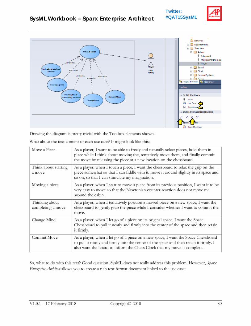
Overall, the use case and sub uses cases might look like this:
SysML Workbook – Sparx Enterprise Architect
V1.0.1 – 17 February 2018 Copyright© 2018 80
Twitter: #QAT15SysML
Drawing the diagram is pretty trivial with the Toolbox elements shown.
What about the text content of each use case? It might look like this:
Move a Piece As a player, I want to be able to freely and naturally select pieces, hold them in place while I think about moving the, tentatively move them, and finally commit the move by releasing the piece at a new location on the chessboard.
Think about starting a move
As a player, when I touch a piece, I want the chessboard to relax the grip on the piece somewhat so that I can fiddle with it, move it around slightly in its space and so on, so that I can stimulate my imagination.
Moving a piece As a player, when I start to move a piece from its previous position, I want it to be very easy to move so that the Newtonian counter-reaction does not move me around the cabin.
Thinking about completing a move
As a player, when I tentatively position a moved piece on a new space, I want the chessboard to gently grab the piece while I consider whether I want to commit the move.
Change Mind As a player, when I let go of a piece on its original space, I want the Space Chessboard to pull it neatly and firmly into the center of the space and then retain it firmly.
Commit Move As a player, when I let go of a piece on a new space, I want the Space Chessboard to pull it neatly and firmly into the center of the space and then retain it firmly. I also want the board to inform the Chess Clock that my move is complete.
So, what to do with this text? Good question. SysML does not really address this problem. However, Sparx Enterprise Architect allows you to create a rich text format document linked to the use case:

SysML Workbook – Sparx Enterprise Architect
V1.0.1 – 17 February 2018 Copyright© 2018 81
Twitter: #QAT15SysML
It is also possible to model it as a SysML Note linked to each Use Case. It depends on the level of effort your organization wants to put into use cases. Writing Effective Use Cases by Alistair Cockburn is widely regarded as the go-to reference for doing really serious use case work. If your organization wants to invest at that level, then you will probably want to develop a formal use case template and link the completed templates for each use case to corresponding SysML element in the model.
Allocate Requirements to Use Cases As mentioned in the tips above, we can also proceed directly from requirements to use cases. Naturally, we would want to allocate requirements to use cases to track this sort of relationship. For this purpose, requirements can be added directly to Use Case diagrams.
Here I have created a simpler Use Case diagram called: “Requirement to Use Case Allocation Example” to demonstrate the point.
Note: when you drag elements onto the diagram, always select “link” not “instance.”
This ends Step 5. Before continuing, save a copy of the project as “Space Chessboard - Step 5.eap”

SysML Workbook – Sparx Enterprise Architect
V1.0.1 – 17 February 2018 Copyright© 2018 82
Twitter: #QAT15SysML

SysML Workbook – Sparx Enterprise Architect
V1.0.1 – 17 February 2018 Copyright© 2018 83
Twitter: #QAT15SysML
Step 6 – Interfaces and Sequence Diagrams
Interfaces SysML has very rich constructs for modeling very complicated interfaces. In fact, interfaces are one of the key areas of interest for the SysML community and substantial changes were made between SysML 1.2 and SysML 1.3.
For the purposes of this tutorial, however, we are just going to do a very simple example using the least complicated approach possible just to give a impression of what sorts of modeling are possible.
Setting Up Your Project File Were you able to complete Step 5 above?
If you did not fully complete Step 5, copy the file “Space Chessboard - Step 5.eap” from the tutorial materials to your project directory and rename it “Space Chessboard.eap”
Add an Interface In Step 5, we looked briefly at the mechanical aspects of the interaction between each chess piece and the chessboard. Here we will look at the control aspect. Clearly the chess piece has to detect the player’s hand as it touches, grabs, moves, and releases the piece. These gestures have to be communicated to the chessboard so that it can control the electromagnet that secures the piece to the board. Obviously, there is an interface between a “Piece” and a “Space” on the chessboard. How is this interface implemented? We don’t know yet. The design team is off looking at options. Some members are lobbying for an optical link. Others think that near field communication (NFC) shows more promise. In any event, we don’t need to know precisely which sort of link will be selected in order to begin modeling what we want the link to do.
1. Add a new top-level package to the model called “Interfaces”
2. Right-click on this package and add a Block Definition Diagram called “Piece to Space Communication”
3. From the “Board” package, drag “Space” onto the diagram.
4. If you get a popup like the one above, just close it.

SysML Workbook – Sparx Enterprise Architect
V1.0.1 – 17 February 2018 Copyright© 2018 84
Twitter: #QAT15SysML
5. From the package “Pieces” drag “Piece” onto the diagram, again closing any popups.
6. From the toolbox, select the “Association Block” link. This is a very important and useful element that was added in SysML 1.3. That is, this element is a relationship that has an attached “block”. This combination thing is very useful because unlike other relationships, this sort of link is a fully featured modeling element in its own right. That means, that we can allocate things to it, make it satisfy requirements, and so on – just what you want from an interface!
7. Drag the link from “Space” to “Piece” in the diagram.
8. At this point a link and a sort of floating block will appear. A panel will open. Name the link “Piece
Control Interface” and click “OK”

SysML Workbook – Sparx Enterprise Architect
V1.0.1 – 17 February 2018 Copyright© 2018 85
Twitter: #QAT15SysML
9. You can move the block around a little to make it look nice.
10. As we can see, we now have a full SysML element for the interface.
Allocating Requirements to the Interface 1. In the package “Requirements” add a new subpackage called “Elaborated Requirements”
2. In “Elaborated Requirements” add a new Requirements diagram called “Piece Control Interface Requirements”
3. From “Clarified Requirements” drag CLR-ERG-004 “Piece Movement” onto the diagram. Fix up the format.
4. Press Alt+5 to make the Toolbox appear.
5. From the Toolbox, drag a requirement to the diagram.
a. Fix up the format
b. Set the name to “Hand Force Sensing”
c. Set the ID to CLR-ERG-004-a
d. Set the text to “Each piece shall sense hand force in excess of 0.02 Newton and report it to the chessboard”
e. Drag a “Derive” relationship from this new requirement to CLR-ERG-004
6. From the Toolbox, drag a requirement to the diagram.
a. Fix up the format
b. Set the name to “Hand Force Sense Data”
c. Set the ID to CLR-ERG-004-a.1
d. Set the text to “The Piece Control Interface shall have a command to support reporting of hand force in units of 0.001 Newtons”
e. Drag a “Derive” relationship from this new requirement to CLR-ERG-004

SysML Workbook – Sparx Enterprise Architect
V1.0.1 – 17 February 2018 Copyright© 2018 86
Twitter: #QAT15SysML
Make a Sequence Diagram for the Interface On the current diagram, select the Interface block and right-click:
Select “New Child Diagram”, “Interaction”, “Sequence Diagram”.

SysML Workbook – Sparx Enterprise Architect
V1.0.1 – 17 February 2018 Copyright© 2018 87
Twitter: #QAT15SysML
Name the diagram “Hand Force Reporting”
Drag elements onto the diagram as shown below:
You will notice that the tool draws the dashed lines and positions the elements vertically automatically. All you can really control is the horizontal spacing. These are referred to by systems engineers as “Swim Lanes”
1. Add an interaction by clicking the interaction icon and then dragging from one swim lane to another
as shown.
2. Double click on the arrow that was added and name it “Push piece to move”.
3. Clicking underneath the arrowhead on the “Piece” swim lane, draw an interaction to the “Space” swim lane.
4. Name that one: “Hand force sensed”
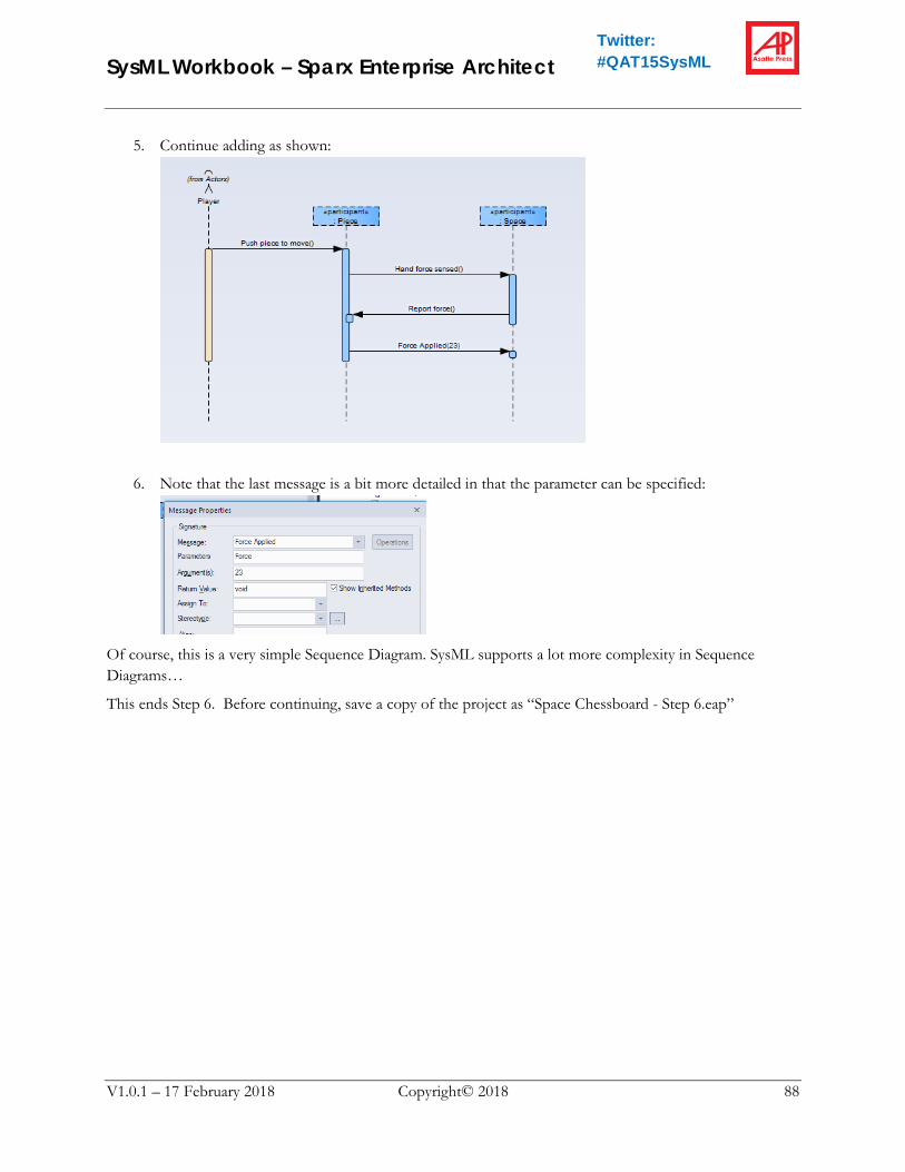
SysML Workbook – Sparx Enterprise Architect
V1.0.1 – 17 February 2018 Copyright© 2018 88
Twitter: #QAT15SysML
5. Continue adding as shown:
6. Note that the last message is a bit more detailed in that the parameter can be specified:
Of course, this is a very simple Sequence Diagram. SysML supports a lot more complexity in Sequence Diagrams…
This ends Step 6. Before continuing, save a copy of the project as “Space Chessboard - Step 6.eap”

SysML Workbook – Sparx Enterprise Architect
V1.0.1 – 17 February 2018 Copyright© 2018 89
Twitter: #QAT15SysML
Step 7 – Test Case So, we are finally at the goal – Test Cases!
The punchline here is that Test Cases in SysML are similar to Use Cases. There really isn’t all that much unique support for them. However, we can use all the other SysML constructs to do a decent job of modeling them.
Add Test Case to a Requirements Diagram
Setting Up Your Project File Were you able to complete Step 6 above?
If you did not fully complete Step 6, copy the file “Space Chessboard - Step 6.eap” from the tutorial materials to your project directory and rename it “Space Chessboard.eap”
Create a Hierarchical Test Plan for the Piece There is no such thing as a “Test Case Diagram”. However, SysML considers test cases to be part of the requirements tool set, so working with a Requirements Diagram is easiest.
1. Right-click on the “Test Cases” package and add a Requirements Diagram called “Piece Test Strategy”
2. Press Alt+5 to make the Toolbar appear if needed.
3. Drag a Test Case onto the diagram and name it “Piece Master Test Plan”
4. From the folder “Clarified Requirements” drag CPY-ERG-003 “Piece Size” to the diagram.
5. Drag another Test Case onto the diagram and name it “Space Walk Glove Movement Test”
6. Drag a “Verify” relationship from this test case to the requirement.
7. From the package “Structure::Pieces” drag “Pawn” onto the diagram.
8. Drag a “Satisfy” relationship from “Pawn” to the requirement.
9. Select the “Containment” relationship and drag it from the Glove Test to the Master Test Plan.
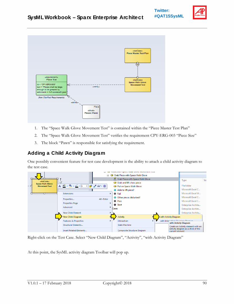
SysML Workbook – Sparx Enterprise Architect
V1.0.1 – 17 February 2018 Copyright© 2018 90
Twitter: #QAT15SysML
1. The “Space Walk Glove Movement Test” is contained within the “Piece Master Test Plan”
2. The “Space Walk Glove Movement Test” verifies the requirement CPY-ERG-003 “Piece Size”
3. The block “Pawn” is responsible for satisfying the requirement.
Adding a Child Activity Diagram One possibly convenient feature for test case development is the ability to attach a child activity diagram to the test case.
Right-click on the Test Case. Select “New Child Diagram”, “Activity”, “with Activity Diagram”
At this point, the SysML activity diagram Toolbar will pop up.

SysML Workbook – Sparx Enterprise Architect
V1.0.1 – 17 February 2018 Copyright© 2018 91
Twitter: #QAT15SysML
…and you can draw something like this pretty easily.
In its basic form, the SysML Activity Diagram is simply what used to be called a “Flow Chart”. Of course, it does have some fancier features which are beyond the scope of this tutorial.
In one final remark, if we right-click on “Grab and lift chess piece”…
We can see that further nesting of diagrams is quite possible. This sort of “Drill-Down” function provides a very nice facility for modeling very complicated test plans at different levels of complexity.
This concludes this tutorial. For your reference, the completed model is available in the file “Space Chessboard – Step 7.eap”.