Embed Size (px)
Citation preview

Cat. No. W141-E1-4
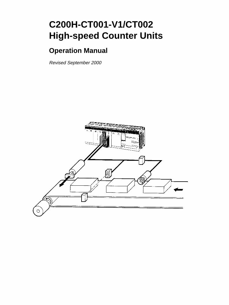
High-speed Counter Units
SYSMAC
C200H-CT001-V1/CT002
C200H-CT001-V1/CT002High-speed Counter Units
Operation Manual
Revised September 2000

iv

!
!
!
v
Notice:OMRON products are manufactured for use according to proper procedures by a qualified operatorand only for the purposes described in this manual.
The following conventions are used to indicate and classify precautions in this manual. Always heedthe information provided with them. Failure to heed precautions can result in injury to people or dam-age to property.
DANGER Indicates an imminently hazardous situation which, if not avoided, will result in death orserious injury.
WARNING Indicates a potentially hazardous situation which, if not avoided, could result in death orserious injury.
Caution Indicates a potentially hazardous situation which, if not avoided, may result in minor ormoderate injury, or property damage.
OMRON Product ReferencesAll OMRON products are capitalized in this manual. The word “Unit” is also capitalized when it refersto an OMRON product, regardless of whether or not it appears in the proper name of the product.
The abbreviation “Ch,” which appears in some displays and on some OMRON products, often means“word” and is abbreviated “Wd” in documentation in this sense.
The abbreviation “PC” means Programmable Controller and is not used as an abbreviation for any-thing else.
Visual AidsThe following headings appear in the left column of the manual to help you locate different types ofinformation.
Note Indicates information of particular interest for efficient and convenient operationof the product.
1, 2, 3... 1. Indicates lists of one sort or another, such as procedures, checklists, etc.
OMRON, 1990All rights reserved. No part of this publication may be reproduced, stored in a retrieval system, or transmitted, in anyform, or by any means, mechanical, electronic, photocopying, recording, or otherwise, without the prior written permis-sion of OMRON.
No patent liability is assumed with respect to the use of the information contained herein. Moreover, because OMRON isconstantly striving to improve its high-quality products, the information contained in this manual is subject to changewithout notice. Every precaution has been taken in the preparation of this manual. Nevertheless, OMRON assumes noresponsibility for errors or omissions. Neither is any liability assumed for damages resulting from the use of the informa-tion contained in this publication.

vi

TABLE OF CONTENTS
vii
PRECAUTIONS . . . . . . . . . . . . . . . . . . . . . . . . . . . . . . . . . 1 Intended Audience . . . . . . . . . . . . . . . . . . . . . . . . . . . . . . . . . . . . . . . . . . . . . . . . . . . . . . . . . . . 2 General Precautions . . . . . . . . . . . . . . . . . . . . . . . . . . . . . . . . . . . . . . . . . . . . . . . . . . . . . . . . . . 3 Safety Precautions . . . . . . . . . . . . . . . . . . . . . . . . . . . . . . . . . . . . . . . . . . . . . . . . . . . . . . . . . . . 4 Operating Environment Precautions . . . . . . . . . . . . . . . . . . . . . . . . . . . . . . . . . . . . . . . . . . . . . 5 Application Precautions . . . . . . . . . . . . . . . . . . . . . . . . . . . . . . . . . . . . . . . . . . . . . . . . . . . . . .
SECTION 1Introduction . . . . . . . . . . . . . . . . . . . . . . . . . . . . . . . . . . . .
1-1 Introduction . . . . . . . . . . . . . . . . . . . . . . . . . . . . . . . . . . . . . . . . . . . . . . . . . . . . . . . . . . . . 1-2 Nomenclature . . . . . . . . . . . . . . . . . . . . . . . . . . . . . . . . . . . . . . . . . . . . . . . . . . . . . . . . . . . 1-3 System Configuration . . . . . . . . . . . . . . . . . . . . . . . . . . . . . . . . . . . . . . . . . . . . . . . . . . . . . 1-4 Operating Modes . . . . . . . . . . . . . . . . . . . . . . . . . . . . . . . . . . . . . . . . . . . . . . . . . . . . . . . .
SECTION 2Switch Settings and Wiring . . . . . . . . . . . . . . . . . . . . . . . .
2-1 Switch Settings . . . . . . . . . . . . . . . . . . . . . . . . . . . . . . . . . . . . . . . . . . . . . . . . . . . . . . . . . . 2-2 Wiring . . . . . . . . . . . . . . . . . . . . . . . . . . . . . . . . . . . . . . . . . . . . . . . . . . . . . . . . . . . . . . . . . 2-3 Input Circuit Wiring Examples . . . . . . . . . . . . . . . . . . . . . . . . . . . . . . . . . . . . . . . . . . . . . 2-4 Dimensions . . . . . . . . . . . . . . . . . . . . . . . . . . . . . . . . . . . . . . . . . . . . . . . . . . . . . . . . . . . . .
SECTION 3Operation . . . . . . . . . . . . . . . . . . . . . . . . . . . . . . . . . . . . . .
3-1 Operational Flow . . . . . . . . . . . . . . . . . . . . . . . . . . . . . . . . . . . . . . . . . . . . . . . . . . . . . . . . 3-2 Input Selection . . . . . . . . . . . . . . . . . . . . . . . . . . . . . . . . . . . . . . . . . . . . . . . . . . . . . . . . . . 3-3 Counter Reset Conditions . . . . . . . . . . . . . . . . . . . . . . . . . . . . . . . . . . . . . . . . . . . . . . . . . 3-4 Data Transfer Timing . . . . . . . . . . . . . . . . . . . . . . . . . . . . . . . . . . . . . . . . . . . . . . . . . . . . .
SECTION 4Data Allocation and Operating Modes . . . . . . . . . . . . . . .
4-1 Data Configuration and Allocation . . . . . . . . . . . . . . . . . . . . . . . . . . . . . . . . . . . . . . . . . . 4-2 Linear and Circular Modes . . . . . . . . . . . . . . . . . . . . . . . . . . . . . . . . . . . . . . . . . . . . . . . . 4-3 Preset Mode . . . . . . . . . . . . . . . . . . . . . . . . . . . . . . . . . . . . . . . . . . . . . . . . . . . . . . . . . . . . 4-4 Gate, Latch, and Sampling Modes . . . . . . . . . . . . . . . . . . . . . . . . . . . . . . . . . . . . . . . . . . .
SECTION 5Error Processing . . . . . . . . . . . . . . . . . . . . . . . . . . . . . . . .
5-1 Error Indications . . . . . . . . . . . . . . . . . . . . . . . . . . . . . . . . . . . . . . . . . . . . . . . . . . . . . . . . . 5-2 Troubleshooting from the PC . . . . . . . . . . . . . . . . . . . . . . . . . . . . . . . . . . . . . . . . . . . . . . .
AppendicesA Error Codes . . . . . . . . . . . . . . . . . . . . . . . . . . . . . . . . . . . . . . . . . . . . . . . . . . . . . . . . . . . . . . . B Specifications . . . . . . . . . . . . . . . . . . . . . . . . . . . . . . . . . . . . . . . . . . . . . . . . . . . . . . . . . . . . . . C IR Area Allocations . . . . . . . . . . . . . . . . . . . . . . . . . . . . . . . . . . . . . . . . . . . . . . . . . . . . . . . . . D DM Area Coding Sheets . . . . . . . . . . . . . . . . . . . . . . . . . . . . . . . . . . . . . . . . . . . . . . . . . . . . .
Index . . . . . . . . . . . . . . . . . . . . . . . . . . . . . . . . . . . . . . . . . .
Revision History . . . . . . . . . . . . . . . . . . . . . . . . . . . . . . . . .

ix
About this Manual:
This manual covers specifications and procedures necessary for the installation and operation of theC200H-CT001-V1 and C200H-CT002 High-speed Counter Units. It includes example system configu-rations to ease the implementation cycle. The C200H-CT001-V1 and C200H-CT002 are Special I/OUnits for C200H PCs. The C200H-CT001-V1 is a high-speed, reversible counter capable of countingat a maximum of 50 kcps. The C200H-CT002 is a high-speed, reversible counter capable of countingat a maximum of 75 kcps.
Please read this manual carefully and be sure you understand the information provided before attemptingto install and operate the C200H-CT001-V1 and C200H-CT002 High-speed Counter Units.
Section 1 contains a brief description of the Units and how they can be used. The Units are displayedand their indicators are explained. An example system configuration is included to demonstrate Unitapplication. The operating modes and their associated ranges of operation are also described.
Section 2 shows the Unit settings and connector cable pin specifications. Instructions for the con-struction of input and output connectors are provided. Electrical schematics and examples are pres-ented to further explain Unit operation.
Section 3 describes the operational flow of the counting system. The input types are identified alongwith instructions for their use. Data transfer timing is described in relation to the PC cycle time.
Section 4 describes the various operating modes in detail. Each mode is described by data alloca-tion, timing charts, commands, flags, and examples. Data formats are explained.
Section 5 presents possible errors and solutions and describes how to handle errors from the PC.The AR area Error and Restart Flags are described.
The following Appendices are also provided: Error Codes, Specifications, IR Area Allocations, andDM Area Coding Sheets.
WARNING Failure to read and understand the information provided in this manual may result inpersonal injury or death, damage to the product, or product failure. Please read eachsection in its entirety and be sure you understand the information provided in the sectionand related sections before attempting any of the procedures or operations given.
!

xi
PRECAUTIONS
This section provides general precautions for using C200H-CT001-V1/CT002 High-speed Counter Units and relateddevices.
The information contained in this section is important for the safe and reliable application of the C200H-CT001-V1/CT002 High-speed Counter Units. You must read this section and understand the information containedbefore attempting to set up or operate a C200H-CT001-V1/CT002 High-speed Counter Unit.
1 Intended Audience . . . . . . . . . . . . . . . . . . . . . . . . . . . . . . . . . . . . . . . . . . . . . . . . . . . . . . . . . . . . 2 General Precautions . . . . . . . . . . . . . . . . . . . . . . . . . . . . . . . . . . . . . . . . . . . . . . . . . . . . . . . . . . . 3 Safety Precautions . . . . . . . . . . . . . . . . . . . . . . . . . . . . . . . . . . . . . . . . . . . . . . . . . . . . . . . . . . . . 4 Operating Environment Precautions . . . . . . . . . . . . . . . . . . . . . . . . . . . . . . . . . . . . . . . . . . . . . . 5 Application Precautions . . . . . . . . . . . . . . . . . . . . . . . . . . . . . . . . . . . . . . . . . . . . . . . . . . . . . . . .
!
!
!
!
3Safety Precautions
xii
1 Intended AudienceThis manual is intended for the following personnel, who must also have knowl-edge of electrical systems (an electrical engineer or the equivalent).
• Personnel in charge of installing FA systems.
• Personnel in charge of designing FA systems.
• Personnel in charge of managing FA systems and facilities.
2 General PrecautionsThe user must operate the product according to the performance specificationsdescribed in the relevant manuals.
Before using the product under conditions which are not described in the manualor applying the product to nuclear control systems, railroad systems, aviationsystems, vehicles, combustion systems, medical equipment, amusement ma-chines, safety equipment, and other systems, machines, and equipment thatmay have a serious influence on lives and property if used improperly, consultyour OMRON representative.
Make sure that the ratings and performance characteristics of the product aresufficient for the systems, machines, and equipment, and be sure to provide thesystems, machines, and equipment with double safety mechanisms.
This manual provides information for programming and operating the Unit. Besure to read this manual before attempting to use the Unit and keep this manualclose at hand for reference during operation.
WARNING It is extremely important that a PC and all PC Units be used for the specifiedpurpose and under the specified conditions, especially in applications that candirectly or indirectly affect human life. You must consult with your OMRONrepresentative before applying a PC system to the above-mentionedapplications.
3 Safety Precautions
WARNING Do not attempt to take any Unit apart while the power is being supplied. Doing somay result in electric shock.
WARNING Do not touch any of the terminals or terminal blocks while the power is beingsupplied. Doing so may result in electric shock.
WARNING Do not attempt to disassemble, repair, or modify any Units. Any attempt to do somay result in malfunction, fire, or electric shock.

!
!
!
!
!
5Application Precautions
xiii
4 Operating Environment Precautions
Caution Do not operate the control system in the following locations:
• Locations subject to direct sunlight.
• Locations subject to temperatures or humidity outside the range specified inthe specifications.
• Locations subject to condensation as the result of severe changes in tempera-ture.
• Locations subject to corrosive or flammable gases.
• Locations subject to dust (especially iron dust) or salts.
• Locations subject to exposure to water, oil, or chemicals.
• Locations subject to shock or vibration.
Caution Take appropriate and sufficient countermeasures when installing systems in thefollowing locations:
• Locations subject to static electricity or other forms of noise.
• Locations subject to strong electromagnetic fields.
• Locations subject to possible exposure to radioactivity.
• Locations close to power supplies.
Caution The operating environment of the PC system can have a large effect on the lon-gevity and reliability of the system. Improper operating environments can lead tomalfunction, failure, and other unforeseeable problems with the PC system. Besure that the operating environment is within the specified conditions at installa-tion and remains within the specified conditions during the life of the system.
5 Application PrecautionsObserve the following precautions when using the PC system.
WARNING Always heed these precautions. Failure to abide by the following precautionscould lead to serious or possibly fatal injury.
• Always ground the system to 100 Ω or less when installing the Units. Not con-necting to a ground of 100 Ω or less may result in electric shock.
• Always turn OFF the power supply to the PC before attempting any of the fol-lowing. Not turning OFF the power supply may result in malfunction or electricshock.
• Mounting or dismounting Power Supply Units, I/O Units, CPU Units,Memory Units, or any other Units.
• Assembling the Units.
• Setting DIP switches or rotary switches.
• Connecting cables or wiring the system.
• Connecting or disconnecting the connectors.
Caution Failure to abide by the following precautions could lead to faulty operation of thePC or the system, or could damage the PC or PC Units. Always heed these pre-cautions.
• Fail-safe measures must be taken by the customer to ensure safety in theevent of incorrect, missing, or abnormal signals caused by broken signal lines,momentary power interruptions, or other causes.

5Application Precautions
xiv
• Interlock circuits, limit circuits, and similar safety measures in external circuits(i.e., not in the Programmable Controller) must be provided by the customer.
• Always use the power supply voltages specified in this manual. An incorrectvoltage may result in malfunction or burning.
• Take appropriate measures to ensure that the specified power with the ratedvoltage and frequency is supplied. Be particularly careful in places where thepower supply is unstable. An incorrect power supply may result in malfunction.
• Install external breakers and take other safety measures against short-circuit-ing in external wiring. Insufficient safety measures against short-circuiting mayresult in burning.
• Do not apply voltages to the Input Units in excess of the rated input voltage.Excess voltages may result in burning.
• Do not apply voltages or connect loads to the Output Units in excess of themaximum switching capacity. Excess voltage or loads may result in burning.
• Disconnect the functional ground terminal when performing withstand voltagetests. Not disconnecting the functional ground terminal may result in burning.
• Be sure that all the mounting screws, terminal screws, and cable connectorscrews are tightened to the torque specified in this manual. Incorrect tighten-ing torque may result in malfunction.
• Leave the label attached to the Unit when wiring. Removing the label may re-sult in malfunction if foreign matter enters the Unit.
• Remove the label after the completion of wiring to ensure proper heat dissipa-tion. Leaving the label attached may result in malfunction.
• Double-check all wiring and switch settings before turning ON the power sup-ply. Incorrect wiring may result in burning.
• Wire correctly. Incorrect wiring may result in burning.
• Mount Units only after checking terminal blocks and connectors completely.
• Be sure that the terminal blocks, Memory Units, expansion cables, and otheritems with locking devices are properly locked into place. Improper lockingmay result in malfunction.
• Check the user program for proper execution before actually running it on theUnit. Not checking the program may result in an unexpected operation.
• Confirm that no adverse effect will occur in the system before attempting any ofthe following. Not doing so may result in an unexpected operation.
• Changing the operating mode of the PC.
• Force-setting/force-resetting any bit in memory.
• Changing the present value of any word or any set value in memory.
• Resume operation only after transferring to the new CPU Unit the contents ofthe DM Area, HR Area, and other data required for resuming operation. Notdoing so may result in an unexpected operation.
• Do not pull on the cables or bend the cables beyond their natural limit. Doingeither of these may break the cables.
• Do not place objects on top of the cables or other wiring lines. Doing so maybreak the cables.
• Use crimp terminals for wiring. Do not connect bare stranded wires directly toterminals. Connection of bare stranded wires may result in burning.
• When replacing parts, be sure to confirm that the rating of a new part is correct.Not doing so may result in malfunction or burning.
• Before touching a Unit, be sure to first touch a grounded metallic object in orderto discharge any static built-up. Not doing so may result in malfunction or dam-age.

1
SECTION 1Introduction
This section introduces the High-speed Counter Unit. It starts by describing Unit nomenclature and then describes thetype of system the Units are generally incorporated it. This section ends with an introduction to the six operating modes,which are described in more detail in Section 4.
1-1 Introduction . . . . . . . . . . . . . . . . . . . . . . . . . . . . . . . . . . . . . . . . . . . . . . . . . . . . . . . . . . . . . 1-2 Nomenclature . . . . . . . . . . . . . . . . . . . . . . . . . . . . . . . . . . . . . . . . . . . . . . . . . . . . . . . . . . . . 1-3 System Configuration . . . . . . . . . . . . . . . . . . . . . . . . . . . . . . . . . . . . . . . . . . . . . . . . . . . . . . 1-4 Operating Modes . . . . . . . . . . . . . . . . . . . . . . . . . . . . . . . . . . . . . . . . . . . . . . . . . . . . . . . . .
2
1-1 IntroductionThe C200H-CT001-V1 and C200H-CT002 are Special I/O Units for C200H PCs.The C200H-CT001-V1 can be connected directly to an incremental encoderwith an open-collector output or source output to function as a high-speed, re-versible counter capable of counting at a maximum of 50 kcps.The C200H-CT002 can be connected directly to an incremental encoder with anRS-422 line driver output or through an Encoder Adapter to an incremental en-coder with a open-collector output to function as a high-speed, reversible count-er capable of counting at a maximum of 75 kcps.The C200H-CT002 is more resistive to noise than the C200H-CT001-V1 andshould be used wherever excessive cable length or a noise-prone environmentis anticipated. Unless otherwise specified, all information presented applies toboth High-Speed Counter Units. Both the High-Speed Counter Units are re-ferred to generically as the Counter Unit.
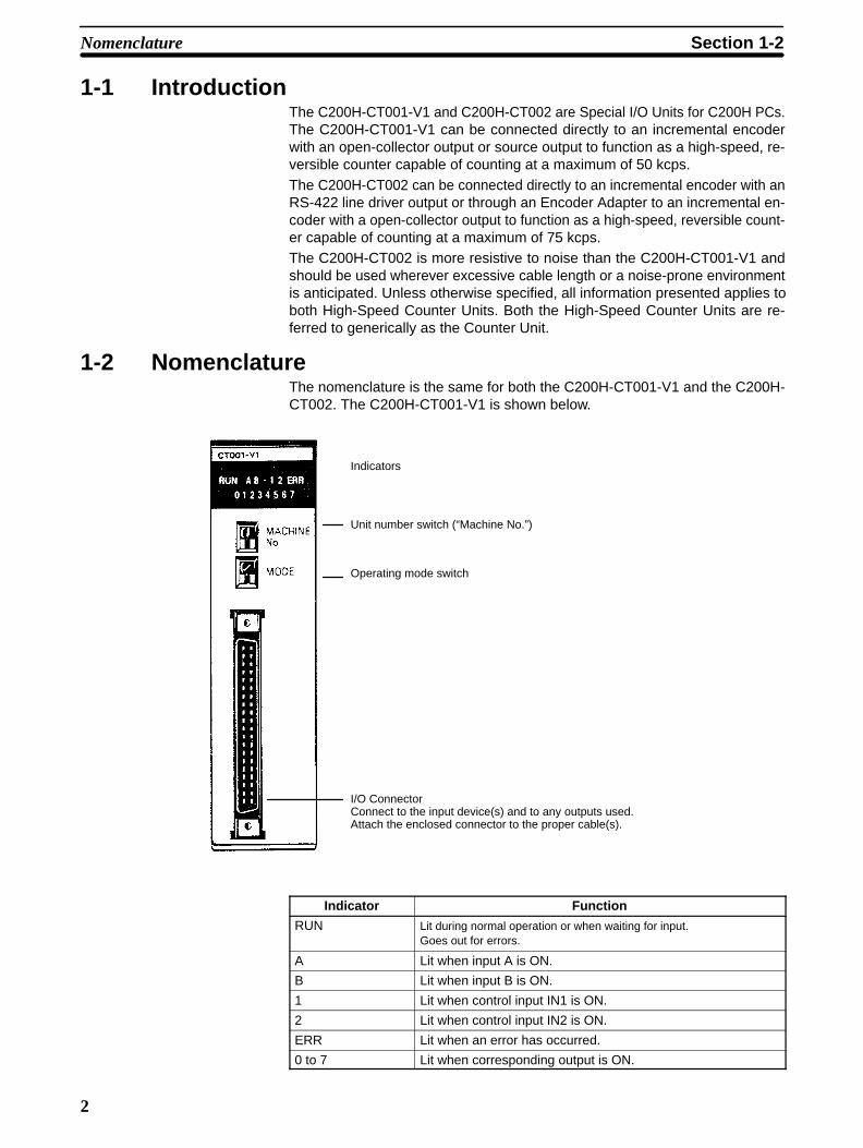
1-2 NomenclatureThe nomenclature is the same for both the C200H-CT001-V1 and the C200H-CT002. The C200H-CT001-V1 is shown below.
Indicators
Unit number switch (“Machine No.”)
Operating mode switch
I/O ConnectorConnect to the input device(s) and to any outputs used.Attach the enclosed connector to the proper cable(s).
Indicator Function
RUN Lit during normal operation or when waiting for input.Goes out for errors.
A Lit when input A is ON.
B Lit when input B is ON.
1 Lit when control input IN1 is ON.
2 Lit when control input IN2 is ON.
ERR Lit when an error has occurred.
0 to 7 Lit when corresponding output is ON.
Nomenclature Section 1-2
3
1-3 System Configuration
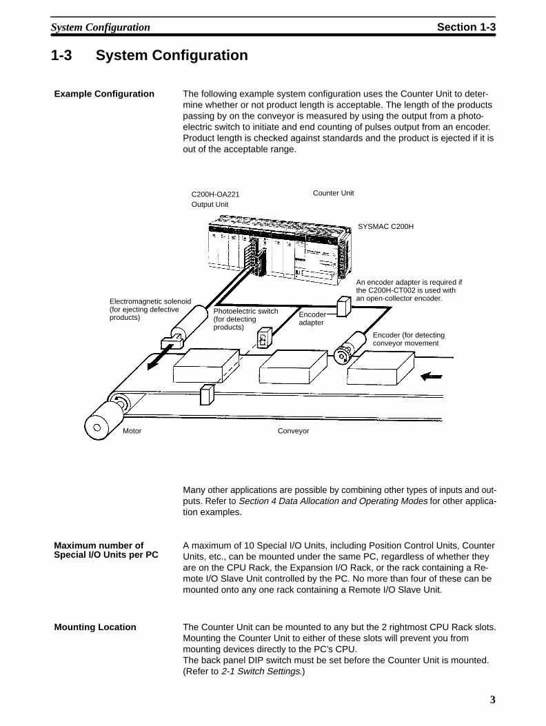
Example Configuration The following example system configuration uses the Counter Unit to deter-mine whether or not product length is acceptable. The length of the productspassing by on the conveyor is measured by using the output from a photo-electric switch to initiate and end counting of pulses output from an encoder.Product length is checked against standards and the product is ejected if it isout of the acceptable range.
C200H-OA221Output Unit
Counter Unit
SYSMAC C200H
An encoder adapter is required ifthe C200H-CT002 is used withan open-collector encoder.
Encoder (for detectingconveyor movement
ConveyorMotor
Photoelectric switch(for detectingproducts)
Electromagnetic solenoid(for ejecting defectiveproducts) Encoder
adapter
Many other applications are possible by combining other types of inputs and out-puts. Refer to Section 4 Data Allocation and Operating Modes for other applica-tion examples.
A maximum of 10 Special I/O Units, including Position Control Units, CounterUnits, etc., can be mounted under the same PC, regardless of whether theyare on the CPU Rack, the Expansion I/O Rack, or the rack containing a Re-mote I/O Slave Unit controlled by the PC. No more than four of these can bemounted onto any one rack containing a Remote I/O Slave Unit.
Mounting Location The Counter Unit can be mounted to any but the 2 rightmost CPU Rack slots.Mounting the Counter Unit to either of these slots will prevent you frommounting devices directly to the PC’s CPU.The back panel DIP switch must be set before the Counter Unit is mounted.(Refer to 2-1 Switch Settings.)
Maximum number ofSpecial I/O Units per PC
System Configuration Section 1-3

4
1-4 Operating ModesThe Counter Unit can be operated in any one of the six operating modes de-scribed below. External outputs are available in only 3 modes: linear, circular,and preset. The function of these outputs depends on the mode. (The mode isselected using the mode selector on the front panel of the Counter Unit, as de-scribed in 2-1 Switch Settings.) The following is merely an introduction to the op-erating modes, all of which are covered in detail in Section 4 Data Allocation andOperating Modes.
Linear Mode In linear mode, the counter value is incremented and decremented between–8,388,608 and 8,388,607 and is continually compared with preset ranges.
When the counter value is within a range (or ranges), specified outputs areturned ON. The same output may be specified for one or more overlappingranges, in which case the output will be turned ON whenever the counter value iswithin one or more of the ranges.
A maximum of 16 ranges may be specified, each with upper and lower limits.
These limits must be within the counter range, i.e., between –8,388,608 and8,388,607. Data can be transferred from the PC to change range limits or to setthe present counter value as desired.
Circular Mode In circular mode, the counter value restarts from zero after reaching a presetmaximum value or returns to the preset maximum value when the countervalue is decremented past zero. In all other respects, including data transfer,circular mode functions exactly as the linear mode. The preset maximum val-ue must be between 0 and 65,535.
Preset Mode In preset mode, the counter value is normally decremented from a presetvalue (between 1 and 8,388,607) to zero, although it can also be increm-ented. During this decrement phase, a total of 3 outputs may be switched ONand OFF according to ON/OFF counter values. When the counter valuereaches zero, a total of 4 outputs may be turned ON, either indefinitely or fora preset time, T. Data can be transferred from the PC to change ON/OFFcounter values as desired.
Gate Mode Two types of gate mode operation are available on the C200H-CT002: nor-mal and cumulative. Only the normal type is available on the C200H-CT001-V1. In normal gate mode, pulses are counted while control input IN1(the count signal) is ON. The counter value is retained when input IN1 goesOFF until input IN1 goes ON again, at which point counting restarts fromzero. In the cumulative type, control input IN1 serves as the reset signal andcounting continues while control input IN2 (the count signal) is ON. Each timeinput IN2 is turned ON, counting continues from the current counter valueuntil it is reset to zero by input IN1. In either type of gate mode, the countingrange is between –8,388,608 and 8,388,607 and counting may be in eitherdirection. This mode does not support data transfer or external outputs fromthe Counter Unit.
Latch Mode In latch mode, counting begins from zero when control input IN1 (count sig-nal) is turned ON and ranges between –8,388,608 and 8,388,607. Pulses arecounted continuously (regardless of whether input IN1 is ON or OFF) , butthe current counter value is always the counter value latched the last timecontrol input IN2 (the latch signal) was turned ON, i.e., the current countervalue remains unchanged while the latch signal (control input IN2) is ON andis updated to the actual count while the latch signal is OFF. Counting may berestarted from zero at any time be activating control input IN1. Control inputs
Operating Modes Section 1-4

5
IN1 and IN2 may originate either externally or internally. This mode does notsupport external outputs from the Counter Unit or data transfer.
Sampling Mode In sampling mode, pulses are counted for a preset interval after control inputIN1 (the count signal) is turned ON. Counting may be in either direction.
Counting always begins at zero and ranges between –8,388,608 and8,388,607. The time interval must be between 10 and 9,999 ms.
Control input IN1 may originate either externally or internally. This mode doesnot support external outputs from the Counter Unit or data transfer.
Operating Modes Section 1-4

7
SECTION 2Switch Settings and Wiring
This section provides the Unit settings and connector cable pin specifications. Instructions for the construction of inputand output connectors are provided. Electrical schematics and examples are presented to further explain Unit operation.
2-1 Switch Settings . . . . . . . . . . . . . . . . . . . . . . . . . . . . . . . . . . . . . . . . . . . . . . . . . . . . . . . . . . . 2-2 Wiring . . . . . . . . . . . . . . . . . . . . . . . . . . . . . . . . . . . . . . . . . . . . . . . . . . . . . . . . . . . . . . . . . . 2-3 Input Circuit Wiring Examples . . . . . . . . . . . . . . . . . . . . . . . . . . . . . . . . . . . . . . . . . . . . . .
2-3-1 C200H-CT001-V1 . . . . . . . . . . . . . . . . . . . . . . . . . . . . . . . . . . . . . . . . . . . . . . . . . 2-3-2 C200H-CT002 . . . . . . . . . . . . . . . . . . . . . . . . . . . . . . . . . . . . . . . . . . . . . . . . . . . .
2-4 Dimensions . . . . . . . . . . . . . . . . . . . . . . . . . . . . . . . . . . . . . . . . . . . . . . . . . . . . . . . . . . . . . .
8
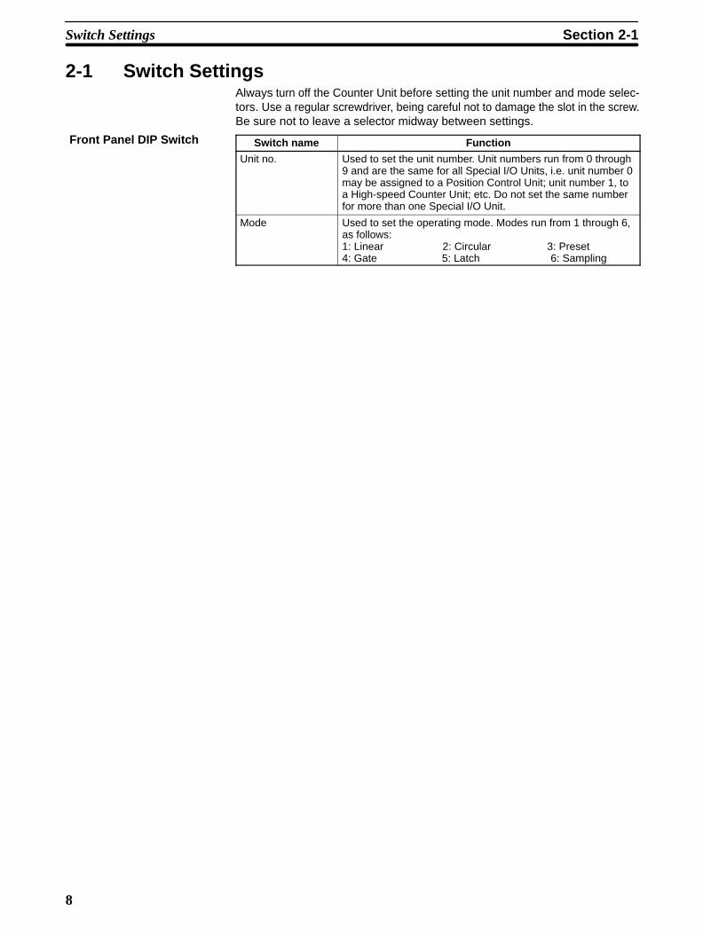
2-1 Switch SettingsAlways turn off the Counter Unit before setting the unit number and mode selec-tors. Use a regular screwdriver, being careful not to damage the slot in the screw.Be sure not to leave a selector midway between settings.
Switch name Function
Unit no. Used to set the unit number. Unit numbers run from 0 through9 and are the same for all Special I/O Units, i.e. unit number 0may be assigned to a Position Control Unit; unit number 1, toa High-speed Counter Unit; etc. Do not set the same numberfor more than one Special I/O Unit.
Mode Used to set the operating mode. Modes run from 1 through 6, as follows:1: Linear 2: Circular 3: Preset4: Gate 5: Latch 6: Sampling
Front Panel DIP Switch
Switch Settings Section 2-1

9
This switch must be set before the Counter Unit is mounted. It is not neces-sary to set all the pins for all operating modes. Refer to 3-2 Input Selectionand Section 4 Data Allocation and Operating Modes for operational details.
1 2 3 Input type
OFF OFF OFF
OFF OFF
OFF
OFF
ON
ON
ON
ONON
*
*
*
Normal
x2
x4
Up and down pulses
Pulse and direction
Offset phases
1 2 3 4 5 6 7 8ON
Input Selection
Pins 1 through 3 are used to select the typeof inputs for inputs A and B.
4 5 Function
OFFON
ONON
Input Z effective on falling edge.
Input Z effective on rising edge.
OFF Input Z inoperative*
For Operating Mode 1 or 2: Input Z
6 7 Function
OFFON
ONON
Control input IN1 effective onfalling edge.
Control input IN1 effective on rising edge.
OFF Control input IN1 inoperative*
This setting is effective only for operatingmodes 1,2, and 3. In modes 4, 5, and 6, control inputs IN1 and IN2are always effective on their rising edges
8 Function
ON Reset bit effective on rising edge.
OFF Reset bit inoperative
This setting is effective only for operatingmodes 1,2, and 3.
Control Input IN1
Internal Reset Bit
4 5 Function
*ON Start on control input IN2.
OFF Start on START command (IR n, bit 00).
*
For Operating Mode 3: Start Input
*Pins marked with asterisks are not used.
Back Panel DIP Switch
Switch Settings Section 2-1

10
2-2 Wiring
Names of inputs and outputs and the pin arrangement of the connector areshown below (as viewed from the front). The connector is a FujitsuFCN-361J040 (solder type), and is included with the Counter Unit.
Row B Pin no. Row A
Input A: 24 VDC 20 Input A: 12 VDC
Input A: 0 V 19 Input A: 5 VDC
Input B: 24 VDC 18 Input B: 12 VDC
Input B: 0 V 17 Input B: 5 VDC
Input Z: 24 VDC 16 Input Z: 12 VDC
Input Z: 0 V 15 Input Z: 5 VDC
14
13 Control input IN1: 12/24 VDC
Control input IN1: 0 V 12 Control input IN1: 5 VDC
11 Control input IN2: 12/24 VDC
Control input IN2: 0 V 10 Control input IN2: 5 VDC
9
Outputs 0 through 3 Power supply: 5 to 24 VDC
8 Output 0
7 Output 1
Outputs 0 through 3, COM: 0 V 6 Output 2
5 Output 3
Outputs 4 through 7 Power supply: 5 to 24 VDC
4 Output 4
3 Output 5
Outputs 4 through 7, COM: 0 V 2 Output 6
1 Output 7
Connector Pin Arrangement
C200H-CT001-V1
Wiring Section 2-2

11
Row B Pin no. Row A
20
Input A: neg. 19 Input A: pos.
18
Input B: neg. 17 Input B: pos.
16
Input Z: neg. 15 Input Z: pos.
14
13 Control input IN1: 12/24 VDC
Control input IN1: 0 V 12 Control input IN1: 5 VDC
11 Control input IN2: 12/24 VDC
Control input IN2: 0 V 10 Control input IN2: 5 VDC
9
Outputs 0 through 3 Power supply: 5 to 24 VDC
8 Output 0
7 Output 1
Outputs 0 through 3, COM: 0 V 6 Output 2
5 Output 3
Outputs 4 through 7 Power supply: 5 to 24 VDC
4 Output 4
3 Output 5
Outputs 4 through 7, COM: 0 V 2 Output 6
1 Output 7
Wiring Connectors Solder-type connectors are included with the Counter Unit.
Use wire with a cross-sectional area of 0.3 mm2 or less. When soldering, do notshort-circuit an adjacent terminal; cover the soldered section with an insulationtube. When using multicore cable, wire output and input cables separately.
Connector
Wire Insulation tube
C200H-CT002
Wiring Section 2-2
12
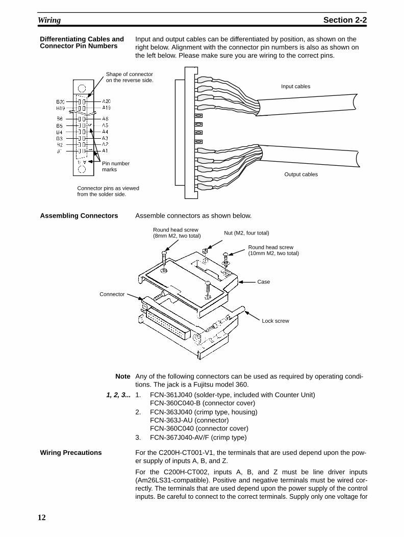
Input and output cables can be differentiated by position, as shown on theright below. Alignment with the connector pin numbers is also as shown onthe left below. Please make sure you are wiring to the correct pins.
Input cables
Output cables
Connector pins as viewedfrom the solder side.
Pin numbermarks
Shape of connectoron the reverse side.
Assembling Connectors Assemble connectors as shown below.
Connector
Round head screw(8mm M2, two total) Nut (M2, four total)
Round head screw (10mm M2, two total)
Case
Lock screw
Note Any of the following connectors can be used as required by operating condi-tions. The jack is a Fujitsu model 360.
1, 2, 3... 1. FCN-361J040 (solder-type, included with Counter Unit)FCN-360C040-B (connector cover)
2. FCN-363J040 (crimp type, housing)FCN-363J-AU (connector)FCN-360C040 (connector cover)
3. FCN-367J040-AV/F (crimp type)
Wiring Precautions For the C200H-CT001-V1, the terminals that are used depend upon the pow-er supply of inputs A, B, and Z.
For the C200H-CT002, inputs A, B, and Z must be line driver inputs(Am26LS31-compatible). Positive and negative terminals must be wired cor-rectly. The terminals that are used depend upon the power supply of the controlinputs. Be careful to connect to the correct terminals. Supply only one voltage for
Differentiating Cables andConnector Pin Numbers
Wiring Section 2-2

13
each input. The terminals for output power supply, 5 to 24 VDC and COM (0 V),are separated into two: those for outputs 0 through 7. These are not intercon-nected internally. If the 5 to 24 VDC and COM (0 V) terminals for the output pow-er supply are connected incorrectly, an internal fuse will burn out, preventing op-eration. This fuse is not user serviceable. This fuse will also burn out if the outputcurrent exceeds 0.5 A/common, again preventing operation. When wiring inputsA, B, and Z, the following measures must be taken to prevent interference fromnoise:
1, 2, 3... 1. Use shielded twisted pair cable and ground the shield.
2. Keep wiring as short as possible and do not place lines parallel to pos-sible sources of noise, such as power lines.
3. Use a stabilized power supply that is independent from other input andoutput power supplies.
The external power supply must be greater than or equal to the load power sup-ply. (An error may occur if the external power supply is less than the load powersupply.) In the example on the following page, E1 must be greater than or equalto E2.
~
Counter Unit5 to 24 VDC B8
A8
A7
A6
A5
B6
Output 0
Output 1
Output 2
Output 3
Fuse COM0.5A (0 V)
Variable resistors
Relay
Relay
Relay
Relay
E1
0 V
E2
0 V
Drivecir-cuit
Input and Output Circuits Actual pin numbers are arranged in order from the top of the connector start-ing with A20 and B20. For each input, connect the 0-V terminal and only oneof the other terminals, i.e., do not supply more than one voltage for any input.The circuits are shown on the following pages.
Wiring Section 2-2

14
C200H-CT001-V1 Input Circuits
Rectifier
B20...... Input A: 24 VDC
A20...... Input A: 12 VDC
A19...... Input A: 5 VDC
B19...... Input A: 0 V
1.6 kΩ
560 Ω
Rectifier
B18...... Input B: 24 VDC
A18...... Input B: 12 VDC
A17...... Input B: 5 VDC
B17...... Input B: 0 V
1.6 kΩ
560 Ω
Rectifier
B16...... Input Z: 24 VDC
A16...... Input Z: 12 VDC
A15...... Input Z: 5 VDC
B15...... Input Z: 0 V
1.6 kΩ
560 Ω
Filter
A13......
A12......
B12......
Control inputIN1: 12/24 VDC
Control inputIN1: 5 VDC
Control inputIN1: 0 V
1.3 kΩ
Filter
A11......
A10......
B10......
Control inputIN1: 12/24 VDC
Control inputIN1: 5 VDC
Control inputIN1: 0 V
1.3 kΩ
Wiring Section 2-2

15
C200H-CT001-V1 Output Circuits
~Fuse0.5 A
B8...... Output powersupply: 5 to 24 VDC
A8...... Output 0
A7...... Output 1
A6...... Output 2
A5...... Output 3
B6...... Output COM: 0 V
~Fuse0.5 A
B4...... Output powersupply: 5 to 24 VDC
A4...... Output 4
A3...... Output 5
A2...... Output 6
A1...... Output 7
B2...... Output COM: 0 V
Wiring Section 2-2

16
C200H-CT002 Input Circuits
A19...... Input A: pos.
B19...... Input A: neg.
A17...... Input B: pos.
B17...... Input B: neg.
A15...... Input Z: pos.
B15...... Input Z: neg.
Filter
A13......
A12......
B15......
Control inputIN1: 12/24 VDC
Control inputIN1: 5 VDC
Control inputIN1: 0 V
1.3 kΩ
Filter
A11......
A10......
B10......
Control inputIN1: 12/24 VDC
Control inputIN1: 5 VDC
Control inputIN1: 0 V
1.3 kΩ
Wiring Section 2-2

17
C200H-CT002 Output Circuits
~Fuse0.5 A
B8...... Output powersupply: 5 to 24 VDC
A8...... Output 0
A7...... Output 1
A6...... Output 2
A5...... Output 3
B6...... Output COM: 0 V
~Fuse0.5A
B4...... Output powersupply: 5 to 24 VDC
A4...... Output 4
A3...... Output 5
A2...... Output 6
A1...... Output 7
B2...... Output COM: 0V
Wiring Section 2-2

18
2-3 Input Circuit Wiring Examples
2-3-1 C200H-CT001-V1
Examples The following wiring examples show connections between encoders and in-puts A, B, and Z.
This example shows the connections that would be used for a 12-VDC powersupply and an incremental encoder with a open-collector output.
Rectifier
Rectifier
Filter
Input A
Input B
Input Z
24 V
12 V
5 V
0 V
24 V
12 V
5 V
0 V
24 V
12 V
5 V
0 V
IA IA
IB IB
IZ IZ
Shielded twisted pair cable
12-VDCpowersupply
12 VDC
0 V
+
–Power supply
EncoderC200H-CT001-V1 Counter Unit
E
Example 112-VDC, Open-collectorEncoder
Input Circuit Wiring Examples Section 2-3

19
This example shows the connections that would be used for a 12-VDC powersupply and a sync-load encoder with a voltage output. When the encoderoutput is high, the input to the Counter Unit turns OFF. When the encoderoutput is low, the input to the Counter Unit turns ON.
Rectifier
Rectifier
Filter
Input A
Input B
Input Z
24 V
12 V
5 V
0 V
24 V
12 V
5 V
0 V
24 V
12 V
5 V
0 V
IA IA
IB IB
IZ IZ
Shielded twisted pair cable
12-VDCpowersupply
12 VDC
0 V
+
–Power supply
EncoderC200H-CT001-V1 Counter Unit
E
Example 212-VDC, Voltage-output,Sync-load Encoder
Input Circuit Wiring Examples Section 2-3

20
This example shows the connections that would be used for a 5-VDC powersupply and a source-load encoder with a voltage output. Here, attention mustbe paid to the ON voltage.
Rectifier
Rectifier
Filter
Input A
Input B
Input Z
24 V
12 V
5 V
0 V
24 V
12 V
5 V
0 V
24 V
12 V
5 V
0 V
IA
IB
IZ
Shielded twisted pair cable
5-VDCpowersupply
5 VDC
0 V
+
– EncoderCT001-V1 Counter Unit
E
Example 35 VDC, Voltage-output,Source-load Encoder
Input Circuit Wiring Examples Section 2-3

21
2-3-2 C200H-CT002
The following wiring examples shows connections between a line-driver en-coder (Am26LS31-compatible) with outputs A, B, Z and inputs A, B, and Z.
E
Input A
Input B
Input Z
Shielded twisted pair cable
+
–
Encoder
–
+
–
+
Power supplyC200H-CT002 Counter Unit
A+
A–
B+
B–
C+
C–
The following wiring example shows connections between an open-collectorencoder and an Encoder Adapter (C500-AE001), and between the EncoderAdapter and inputs A, B, and Z. Connections should be wired so that CounterUnit inputs go ON when encoder outputs go ON. Because the C500-AE001Encoder Adapter uses an Am26LS31-compatible line driver, high voltage isimpressed on the positive terminal and low voltage is impressed on the nega-tive terminal when the output is high.
E
Input A
Input B
Input Z
Shielded twisted pair cable+
–
–+
–+
C200H-CT002 Counter Unit
E
Shieldedtwistedpair cable
C500-AE001 En-coder Adapter
5- to12-VDCpowersupply
A–
A+
B–
B+
Z–
Z+
VCC
0 VVCC
0 VVCC
0 V
Encoder
Voltageregulator
+
–
Example 1Line-driver Encoder
Example 2Open-collector Encoderand Encoder Adapter
Input Circuit Wiring Examples Section 2-3

22
In order to prevent chattering, install the input wiring with as few contacts aspossible.
Sensoroutput
Filter
Filter
Sensoroutput
12- to24-VDCpowersupply
12 to 24 VDC
0 V
Twisted pair cable
Sensor
Counter Unit
Control input IN112/24 V
5 V
0 V
12/24 V
5 V
0 V
–
+
Sensor
Control Input WiringExamples
Input Circuit Wiring Examples Section 2-3

23
The following example shows output wiring with outputs 0 through 3 con-nected to relays and outputs 4 through 7 connected to TTL devices.
~
Counter Unit5 to 24 VDC A8
A8
A7
A6
A5
B6
Output 0
Output 1
Output 2
Output 3
Fuse COM0.5 A (0 V)
Variable resistors
Relay
Relay
Relay
Relay
0 V
~
Counter Unit5 to 24 VDC B4
A4
A3
A2
A1
B2
Output 4
Output 5
Output 6
Output 7
Fuse COM0.5 A (0 V)
5 VDC
0 V
5 VDC
Output 4
Output 5
Output 6
Output 7
Buffers
Pull-up resistors(4.7 kΩ)
+
–
5 to 24 VDC
5- to24-VDCpowersupply
+
–
Switching capacitydepends upon thevoltage. Refer to Ap-pendix B Specifica-tions.
Output ON.
Output OFF.
Low
High
Output Voltages for Outputs 0 through 7
Driv
e ci
rcui
tD
rive
circ
uit
External Output WiringExample
Input Circuit Wiring Examples Section 2-3

24
2-4 DimensionsUnit Dimensions (Unit: mm)
130
35 100.5
Mounted Dimensions (Unit: mm)
117
Approx. 200
Connectingcable
Rack
Dimensions Section 2-4

25
SECTION 3Operation
This section describes the operational flow of the counting system. The input types are identified along with instructionsfor their use. Data transfer timing is described in relation to the PC cycle time.
3-1 Operational Flow . . . . . . . . . . . . . . . . . . . . . . . . . . . . . . . . . . . . . . . . . . . . . . . . . . . . . . . . . 3-2 Input Selection . . . . . . . . . . . . . . . . . . . . . . . . . . . . . . . . . . . . . . . . . . . . . . . . . . . . . . . . . . .
3-2-1 Offset Phases . . . . . . . . . . . . . . . . . . . . . . . . . . . . . . . . . . . . . . . . . . . . . . . . . . . . . 3-2-2 Up and Down Pulses . . . . . . . . . . . . . . . . . . . . . . . . . . . . . . . . . . . . . . . . . . . . . . . 3-2-3 Pulse and Direction . . . . . . . . . . . . . . . . . . . . . . . . . . . . . . . . . . . . . . . . . . . . . . . .
3-3 Counter Reset Conditions . . . . . . . . . . . . . . . . . . . . . . . . . . . . . . . . . . . . . . . . . . . . . . . . . . . 3-4 Data Transfer Timing . . . . . . . . . . . . . . . . . . . . . . . . . . . . . . . . . . . . . . . . . . . . . . . . . . . . . .

26
3-1 Operational FlowEach Special I/O Unit mounted under a C200H PC is assigned a unit numberbetween 0 and 9. The unit number assigned to the Counter Unit determines the100 DM words and 10 IR words that will be allocated to it. DM words are used forCounter Unit parameters; IR words, for command bits and flags. (Refer to 4-1Data Configuration and Allocation for details.) The following procedure outlinesthe steps necessary to operate the Counter Unit.
1, 2, 3... 1. Set the mode selector on the front panel to the desired operating mode, and then set the DIP switch on the rear panel accordingly. (Refer to 2-1Switch Settings.)
2. Set the unit number with the selector on the front panel. (Refer to 2-1Switch Settings.)
3. Using the Programming Console, set data required in the DM area un-der the unit number.
4. Prepare the user program to operate the Counter Unit using the allo-cated IR area words and bits.
It is also possible to set parameters and counter values in any data area usingthe user program or the Programming Console. This data can then be trans-ferred to the Counter Unit by using the TRANSFER DATA command bit. (Referto page 40 TRANSFER DATA Command.)
3-2 Input SelectionAny one of three types of inputs can be selected: offset phase inputs (i.e., twoinputs with offset phases), individual up and down inputs, and pulse and direc-tion inputs. All three types of inputs include a reset input. Any type of any inputcan be used with any of the operating modes, although not all operating modessupport resetting. (Refer to Section 4 Data allocation and Operating Modes fordetails.) The type of inputs is selected with the back panel DIP switch.
3-2-1 Offset PhasesOffset phase inputs use the difference in phase between two inputs to determinewhether the counter value will be incremented or decremented. An input multi-plier, either x 2 or x 4, is available with offset phase inputs to increase accuracy. Ifthe x 2 multiplier is selected, the counter value will be incremented or decre-mented twice for each input A pulse; if the x 4 multiplier is selected, the countervalue will be incremented or decremented four times for each input A pulse. Themultiplier is set with the back panel DIP switch. (Refer to 2-1 Switch Settings.)The counter can be reset in the linear or circular operating modes by using theZ-phase output of the encoder. Refer to 3-3 Reset Conditions for details.
Phase A
Phase B
Phase Z (reset input)
Input A
Input B
Input Z
Wire accordingto the countingdirection
Encoder
Counter Unit
Counting Speed The maximum pulse frequency possible for offset phase inputs is determinedby the specifications of the incremental encoder connected to the Counter
Input Selection Section 3-2

27
Units. The following example shows calculations E6B-CWZ3C IncrementalEncoder when used with the C200H-CT001-V1. Rotational directions are giv-en as viewed from the end of the encoder shaft.
Power supply 4.75 to 13.2 VDC, ripple (p-p): 5% max.
Current consumption 50 mA max.
Resolution 500 pulses/revolution
Outputs Phase A, phase B, phase Z
Output type Open collector
Output capacity Applied voltage: 30 VDC max.Sync. current: 80 mA max.Residual voltage: 1 V max
Max. frequency 30 kHz
Output phase difference(between phase A and B)
90°±45° (1/4T±1/8T)
Output fall/rise time 1.0 µs max.
CW Rotation Here, input A is advanced by 1/4T±1/8T over input B.
1/4 T±1/8 T (90°±45°)
ON
OFF
ON
OFF
Input A
Input B
T(360°)
Towards CW
CCW Rotation Here, input A is delayed by 1/4T±1/8T over input B.
1/4 T + 1/8 T (90°+ 45°)
ON
OFF
ON
OFF
Input A
Input B
T(360°)
Towards CCW
Since the output phase difference is 90°±45°, the minimum phase differenceproduced by this encoder is as follows:
90° – 45° = 45°Because the C200H-CT001-V1 requires a minimum phase difference of 4.5 4.5must be less than 45°/360°. T must therefore be less than 36 meaning the maxi-mum frequency, 1/T, would be 27.7 kcps (54 rps for 500 pulses per revolution).This would be the maximum frequency at which this encoder could be used withthe C200H-CT001-V1. With the C200H-CT002, a minimum phase difference of3 is required. Computing as above shows a maximum frequency of 41.7 kcpswhen using the C200H-CT002 with this encoder.
Note The minimum pulse width must be considered when using input Z to resetthe counter. With the C200H-CT001-V1, the pulse width of input Z must be0.1 ms or greater, and the return frequency must be 5 kcps or less. With the
Encoder Specifications
Input Selection Section 3-2
28
C200H-CT002, the pulse width of input Z must be 10 or greater, and the re-turn frequency, allowing for software processing time, must be 10 kcps orless.
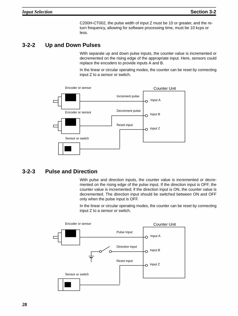
3-2-2 Up and Down PulsesWith separate up and down pulse inputs, the counter value is incremented ordecremented on the rising edge of the appropriate input. Here, sensors couldreplace the encoders to provide inputs A and B.
In the linear or circular operating modes, the counter can be reset by connectinginput Z to a sensor or switch.
Encoder or sensor
Input A
Input B
Input Z
Encoder or sensor
Sensor or switch
Increment pulse
Decrement pulse
Reset input
Counter Unit
3-2-3 Pulse and DirectionWith pulse and direction inputs, the counter value is incremented or decre-mented on the rising edge of the pulse input. If the direction input is OFF, thecounter value is incremented; if the direction input is ON, the counter value isdecremented. The direction input should be switched between ON and OFFonly when the pulse input is OFF.
In the linear or circular operating modes, the counter can be reset by connectinginput Z to a sensor or switch.
Input A
Input B
Input Z
Encoder or sensor
Sensor or switch
Pulse Input
Direction input
Reset input
Counter Unit
Input Selection Section 3-2
29
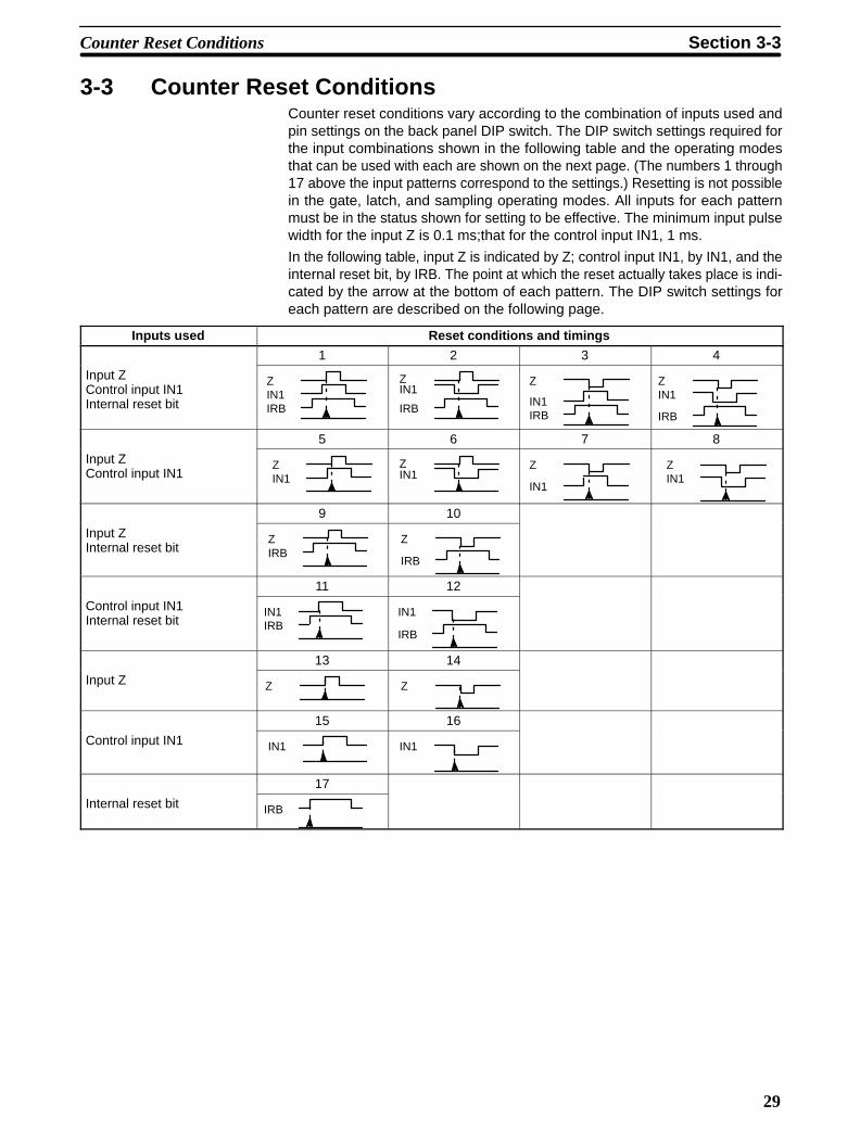
3-3 Counter Reset ConditionsCounter reset conditions vary according to the combination of inputs used andpin settings on the back panel DIP switch. The DIP switch settings required forthe input combinations shown in the following table and the operating modesthat can be used with each are shown on the next page. (The numbers 1 through17 above the input patterns correspond to the settings.) Resetting is not possiblein the gate, latch, and sampling operating modes. All inputs for each patternmust be in the status shown for setting to be effective. The minimum input pulsewidth for the input Z is 0.1 ms;that for the control input IN1, 1 ms.
In the following table, input Z is indicated by Z; control input IN1, by IN1, and theinternal reset bit, by IRB. The point at which the reset actually takes place is indi-cated by the arrow at the bottom of each pattern. The DIP switch settings foreach pattern are described on the following page.
Inputs used Reset conditions and timings
1 2 3 4
Input ZControl input IN1Internal reset bit
ZIN1IRB
ZIN1
IRB
Z
IN1IRB
ZIN1
IRB
5 6 7 8
Input ZControl input IN1
ZIN1
ZIN1
Z
IN1
ZIN1
9 10
Input ZInternal reset bit
ZIRB
Z
IRB
11 12
Control input IN1Internal reset bit
IN1IRB
IN1
IRB
13 14
Input Z Z Z
15 16
Control input IN1 IN1 IN1
17
Internal reset bit IRB
Counter Reset Conditions Section 3-3

30
DIP Switch Settings Pins 1 through 3 do not affect resetting
Pattern number onprevious page
Pin Settings Possible operating modes
4 5 6 7 8 Linear Circular Preset
1 ON ON ON ON ON OK OK OK
2 ON ON ON OFF ON OK OK OK
3 ON OFF ON ON ON OK OK OK
4 ON OFF ON OFF ON OK OK OK
5 ON ON ON ON OFF OK OK OK
6 ON ON ON OFF OFF OK OK OK
7 ON OFF ON ON OFF OK OK OK
8 ON OFF ON OFF OFF OK OK OK
9 ON ON OFF * ON OK OK OK
10 ON OFF OFF * ON OK OK OK
11 OFF * ON ON ON OK OK OK
12 OFF * ON OFF ON OK OK OK
13 ON ON OFF * OFF OK OK OK
14 ON OFF OFF * OFF OK OK OK
15 OFF * ON ON OFF OK OK OK
16 OFF * ON OFF OFF OK OK OK
17 OFF * OFF * ON OK OK OK
*These pins may be either ON or OFF.
3-4 Data Transfer TimingData transfer is available in linear and circular modes to change ranges limit set-tings or the current counter value and in preset mode to change range limit set-tings. The data to be transferred must be prepared in the appropriate form in aPC data area. Data transfer specifications and procedures are described underthe relevant operating modes. This section describes only data transfer timing inrelation to the PC cycle time.
C200H Cycle Time The C200H PC cycle consists of the following operations.
Com-monprocess-ing
Hostlinkservic-ing
Periph-eral de-viceservic-ing
ProcessingI/O re-freshcycle
Com-monprocess-ing
Hostlinkservic-ing
Periph-eral de-viceservic-ing
ProcessingI/O re-freshcycle
Cycle time Cycle time
Data Transfer Timing Section 3-4
31
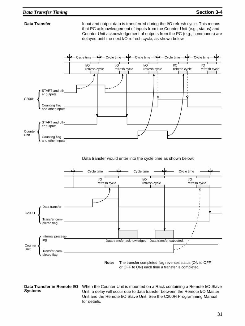
Data Transfer Input and output data is transferred during the I/O refresh cycle. This meansthat PC acknowledgement of inputs from the Counter Unit (e.g., status) andCounter Unit acknowledgement of outputs from the PC (e.g., commands) aredelayed until the next I/O refresh cycle, as shown below.
Cycle time Cycle time Cycle time Cycle time Cycle time
I/Orefresh cycle
I/Orefresh cycle
I/Orefresh cycle
I/Orefresh cycle
I/Orefresh cycle
START and oth-er outputs
Counting flagand other inputs
START and oth-er outputs
Counting flagand other inputs
C200H
CounterUnit
Data transfer would enter into the cycle time as shown below:
Cycle time Cycle time Cycle time
I/Orefresh cycle
Data transfer
Transfer com-pleted flag
Internal process-ing
Transfer com-pleted flag
C200H
CounterUnit
I/Orefresh cycle
I/Orefresh cycle
Data transfer acknowledged. Data transfer executed.
Note: The transfer completed flag reverses status (ON to OFFor OFF to ON) each time a transfer is completed.
When the Counter Unit is mounted on a Rack containing a Remote I/O SlaveUnit, a delay will occur due to data transfer between the Remote I/O MasterUnit and the Remote I/O Slave Unit. See the C200H Programming Manualfor details.
Data Transfer in Remote I/OSystems
Data Transfer Timing Section 3-4

33
SECTION 4Data Allocation and Operating Modes
This section describes the various operating modes in detail. Each mode is described by data allocation, timing charts,commands, flags, and examples. Data formats are explained.
4-1 Data Configuration and Allocation . . . . . . . . . . . . . . . . . . . . . . . . . . . . . . . . . . . . . . . . . . . 4-2 Linear and Circular Modes . . . . . . . . . . . . . . . . . . . . . . . . . . . . . . . . . . . . . . . . . . . . . . . . . .
4-2-1 Data Allocation . . . . . . . . . . . . . . . . . . . . . . . . . . . . . . . . . . . . . . . . . . . . . . . . . . . 4-2-2 DM Area Settings . . . . . . . . . . . . . . . . . . . . . . . . . . . . . . . . . . . . . . . . . . . . . . . . . 4-2-3 IR Area Settings . . . . . . . . . . . . . . . . . . . . . . . . . . . . . . . . . . . . . . . . . . . . . . . . . . . 4-2-4 Timing Chart . . . . . . . . . . . . . . . . . . . . . . . . . . . . . . . . . . . . . . . . . . . . . . . . . . . . . 4-2-5 Application Examples . . . . . . . . . . . . . . . . . . . . . . . . . . . . . . . . . . . . . . . . . . . . . .
4-3 Preset Mode . . . . . . . . . . . . . . . . . . . . . . . . . . . . . . . . . . . . . . . . . . . . . . . . . . . . . . . . . . . . . 4-3-1 Data Allocation . . . . . . . . . . . . . . . . . . . . . . . . . . . . . . . . . . . . . . . . . . . . . . . . . . . 4-3-2 DM Area Settings . . . . . . . . . . . . . . . . . . . . . . . . . . . . . . . . . . . . . . . . . . . . . . . . . 4-3-3 IR Area Settings . . . . . . . . . . . . . . . . . . . . . . . . . . . . . . . . . . . . . . . . . . . . . . . . . . . 4-3-4 Timing Chart . . . . . . . . . . . . . . . . . . . . . . . . . . . . . . . . . . . . . . . . . . . . . . . . . . . . . 4-3-5 Application Example . . . . . . . . . . . . . . . . . . . . . . . . . . . . . . . . . . . . . . . . . . . . . . .
4-4 Gate, Latch, and Sampling Modes . . . . . . . . . . . . . . . . . . . . . . . . . . . . . . . . . . . . . . . . . . . . 4-4-1 Data Allocation . . . . . . . . . . . . . . . . . . . . . . . . . . . . . . . . . . . . . . . . . . . . . . . . . . . 4-4-2 DM Area Settings . . . . . . . . . . . . . . . . . . . . . . . . . . . . . . . . . . . . . . . . . . . . . . . . . 4-4-3 IR Area Settings . . . . . . . . . . . . . . . . . . . . . . . . . . . . . . . . . . . . . . . . . . . . . . . . . . . 4-4-4 Timing Charts . . . . . . . . . . . . . . . . . . . . . . . . . . . . . . . . . . . . . . . . . . . . . . . . . . . . 4-4-5 Application Examples . . . . . . . . . . . . . . . . . . . . . . . . . . . . . . . . . . . . . . . . . . . . . .
34
4-1 Data Configuration and AllocationIR words 100 through 199 are allocated as I/O refresh areas. Each Counter Unitis allocated 10 consecutive words (although not all modes use all 10 words). Thefirst IR word for each Counter Unit, designated in this manual as n, can be com-puted from the unit numbers as follows:
n = 100 + 10 x unit number.
IR words are refreshed during the PC’s I/O refresh cycle. Note that input and out-put designations are in reference to the PC, e.g., command bits are outputs, sta-tus bits are inputs.
Each Counter Unit is also allocated 100 consecutive words as a parameter area(although not all modes use all 100 words). These words are in the DM area andrun from DM 1000 through DM 1999. The first DM word for each Counter Unit, m,can also be computed from the unit number:
m = 1000 + 100 x unit number.
All DM area data for the Counter Unit is transferred to it whenever power isturned ON or the Counter Unit is reset.
Data Configuration and Allocation Section 4-1

35
These allocations are shown below for all unit numbers. Details of allocationswithin these words are given under the operating modes to which they apply. Aquick overview of word and bit allocations is available in Appendix C IR Area Al-locations and Appendix D DM Area Coding Sheets.
DM 1000 through 1099Unit #0
DM 1100 through 1199Unit #1
DM 1200 through 1299Unit #2
DM 1300 through 1399Unit #3
DM 1400 through 1499Unit #4
DM 1500 through 1599Unit #5
DM 1600 through 1699Unit #6
DM 1700 through 1799Unit #7
DM 1800 through 1899Unit #8
DM 1900 through 1999Unit #9
100 through 109Unit #0
110 through 119Unit #1
120 through 129Unit #2
130 through 139Unit #3
140 through 149Unit #4
150 through 159Unit #5
160 through 169Unit #6
170 through 179Unit #7
180 through 189Unit #8
190 through 199Unit #9
Specified Data Area(DM, fixed DM, I/O, LR, HR, or AR)
IR area
DM area
Parameter area
∫
Word m
Word m+99
Output data area
Input data area
Word n to n+4
Word n+4 to n+9
I/O Area
Data is automatical-ly transferred to theCounter Unit whenpower is turned orwhen its restart flagin the AR area isturned ON.
Data transfer
Data is transferredwhen TRANSFERDATA is set.
Data is trans-ferred to theCounter Unit eachI/O refresh.
C200H PC Counter Unit
Data is transferred to the Counter Unitwhen the TRANSFER DATA commandbit of the IR area si turned ON after set-ting the TRANSFER DATA command tothe specified data area.
Data Configuration and Allocation Section 4-1

36
Data Format Data is allocated by either bit or by word, though it is often input and outputby decimal digit, i.e., four bits (BCD), or by hexadecimal digit. Counter val-ues, upper and lower limits of ranges, and some other data are held in twoadjacent words, sometimes with a sign digit, in the following format.
sign x 106 x 105 x 104 x 103 x 102 x 101 x 100
0
1
+
–
Highest word Lowest word
Note that the rightmost word is always the lowest word, i.e., if the two words werem+10 and m+11, the rightmost word would be m+10; the leftmost, m+11. Fur-thermore, the rightmost digit in each word begins in the lowest bits, i.e., the digitsx 104 and x 100 above would be held in, bits 00 through 03 of their respectivewords. Even when only one word or part of a word is required to hold data, e.g.,the error code or error location, the rightmost digit is also always held in the lowerbits. Although decimal notation is generally used for data in this manual, data ishandled in the system as binary-coded decimal (BCD) unless otherwise noted.Note that this data is generally input as decimal, whereas hexadecimal data isinput as hexadecimal. The number of digits given for certain data refers to thedecimal digits, e.g., “7 digits with sign” indicates that the lowest word and right-most 12 bits of the highest word are allocated to the 7-digit decimal value; theleftmost four bits are allocated to the sign digit.
4-2 Linear and Circular ModesIn both linear and circular modes counter values are incremented and decre-mented according to any of the three types of input pulses. All functional aspectand data allocations for these two modes are the same, except that in linearmode, counter values range linearly between –8,388,608 and 8,388,607, whilein circular mode, counter values range from 0 to a preset maximum value (usedonly in circular mode), with the maximum value and 0 being adjacent to eachother in sequence. That is, decrementing below 0 results in the current countervalue going to the maximum value; incrementing past the maximum value re-sults in the current counter value going to zero.Both modes provide 16 outputs, all of which can be output internally (i.e., to thePC) and eight of which can be output externally (i.e., without passing through thePC) as well as internally. These outputs are sometimes referred to by numberand sometimes as either internal inputs and external inputs. The term internaloutputs refers to all outputs sent to the PC; external outputs, to all outputs set tothe external connector.Both modes provide 16 ranges for counter values during which the outputs canbe set to turn ON. These ranges can be enabled or disabled during operations.Data transfer from the PC data area is also available in both modes to changeeither range settings or the current counter value.Although control input IN1 is supposed by both modes, control input IN2 is notused.
Note Stop counter operation before changing the present value to 0 or resettingthe Counter Unit in the ring mode. If either of these is performed withoutstopping counter operation, the maximum value preset operation will not beperformed correctly.
4-2-1 Data AllocationThe commands, parameters, flags, and other information in the following tablesare described in detail in 4-2-2 DM Area Settings and 4-2-3 IR Area Settings.
Linear and Circular Modes Section 4-2

37
DM Area The DM area contains user parameters that are to be set into the CounterUnit, including the operating mode and output range limits. The first DM wordfor each Counter Unit is indicated by m and equals 1,000 plus 100 times theunit number.
Word Bit Function
m 07 through 00 Set to 0.
11 through 08 Operating mode (Here, either 1: linear or 2: circular)
15 through 12 Set to 0.
m + 1 15 through 00 Effective range bits (bit numbers correspond to range numbers)
m + 2 15 through 00 Maximum counter value (for circular mode only)
m + 3 15 through 00 6 digits (Bits 15 to 04 not used.)
m + 4m + 9
Not used.
m + 10 15 through 00 Lower limit for range #0, 7 digits with sign digit
m + 11 15 through 00
m + 12 15 through 00 Upper limit for range #0, 7 digits with sign digit
m + 13 15 through 00
m + 14 15 through 00 Output pattern for range #0 (bit numbers correspond to output numbers)
m + 15m + 19
Lower limit, upper limit, and output pattern for range #1 (Format same asthat for range #0.)
m + 20m + 24
Lower limit, upper limit, and output pattern for range #2 (Format same asthat for range #0.)
m + 25m + 29
Lower limit, upper limit, and output pattern for range #3 (Format same asthat for range #0.)
m + 30m + 34
Lower limit, upper limit, and output pattern for range #4 (Format same asthat for range #0.)
m + 35m + 39
Lower limit, upper limit, and output pattern for range #5 (Format same asthat for range #0.)
m + 40m + 44
Lower limit, upper limit, and output pattern for range #6 (Format same asthat for range #0.)
m + 45m + 49
Lower limit, upper limit, and output pattern for range #7 (Format same asthat for range #0.)
m + 50m + 54
Lower limit, upper limit, and output pattern for range #8 (Format same asthat for range #0.)
m + 55m + 59
Lower limit, upper limit, and output pattern for range #9 (Format same asthat for range #0.)
m + 60m + 64
Lower limit, upper limit, and output pattern for range #10 (Format same asthat for range #0.)
m + 65m + 69
Lower limit, upper limit, and output pattern for range #11 (Format same asthat for range #0.)
m + 70m + 74
Lower limit, upper limit, and output pattern for range #12 (Format same asthat for range #0.)
m + 75m + 79
Lower limit, upper limit, and output pattern for range #13 (Format same asthat for range #0.)
m + 80m + 84
Lower limit, upper limit, and output pattern for range #14 (Format same asthat for range #0.)
m + 85m + 89
Lower limit, upper limit, and output pattern for range #15 (Format same asthat for range #0.)
m + 89m + 99
Not used.
Linear and Circular Modes Section 4-2

38
IR Area The IR area contains commands and status information. Inputs and outputsare given in reference to the PC, i.e., output data is sent from the PC to theCounter Unit; input data, from the Counter Unit to the PC. The first IR wordfor each Counter Unit is indicated by n and equals 100 plus 10 times the unitnumber.
Word Bit Function
00
01
02
03
04
05
06
07
08
09
10
11
12
13
14
15
00
01
02
03
04
05
06
07
08
09
10
11
12
13
14
15
START command
TRANSFER DATA command
ENABLE OUTPUT command
Not used.
CHANGE RANGES command
READ ERROR command
RESET COUNTER command
ENABLE FORCED OUTPUT command
Output #0 force bit
Output #1 force bit
Output #2 force bit
Output #3 force bit
Output #4 force bit
Output #5 force bit
Output #6 force bit
Output #7 force bit
Range #0 enable bit
Range #1 enable bit
Range #2 enable bit
Range #3 enable bit
Range #4 enable bit
Range #5 enable bit
Range #6 enable bit
Range #7 enable bit
Range #8 enable bit
Range #9 enable bit
Range #10 enable bit
Range #11 enable bit
Range #12 enable bit
Range #13 enable bit
Range #14 enable bit
Range #15 enable bit
n+2 15−00
n+3
03−00
07−04
15−08
TRANSFER DATA beginning wordnumber, 4 digits
TRANSFER DATA data area, 0 to 4
Not used. (Set to 0.)
Number of transfers, 1 to 3
n
n+1
Word Bit Function
00
01
02
03
04
05
06
07
08
09
10
11
12
13
14
15
00
01
02
03
04
05
06
07
08
09
10
11
12
1314
15
n+8
n+9
00
01
02
03
04
05
06
07
08
n+4
Counting flag
Z flag
IN1 flag
IN2 flag
Transfer completed flag
Error flag
Count overflow flag
Reset flag
Not usedError location
Error code
Current counter value, 7 digits with sign(–8,388,608 to +8,388,607)
Range #0 flag
Range #1 flag
Range #2 flag
Range #3 flag
Range #4 flag
Range #5 flag
Range #6 flag
Range #7 flag
Range #8 flag
Range #9 flag
Range #10 flag
Range #11 flag
Range #12 flag
Range #13 flag
Range #14 flag
Range #15 flag
Output #0 flag (external output possible)
Output #1 flag (external output possible)
Output #2 flag (external output possible)
Output #3 flag (external output possible)
Output #4 flag (external output possible)
Output #5 flag (external output possible)
Output #6 flag (external output possible)
Output #7 flag (external output possible)
Output #8 flag (internal output only)
15−08
07−00
15−0015−00
n+5
n+6n+7
Outputs Inputs
Output #9 flag (internal output only)
Output #10 flag (internal output only)
Output #11 flag (internal output only)
Output #12 flag (internal output only)
Output #13 flag (internal output only)Output #14 flag (internal output only)
Output #15 flag (internal output only)
Linear and Circular Modes Section 4-2

39
4-2-2 DM Area Settings
Operating Mode DM word m, bits 11 through 08
The operating mode is set with the mode selector on the front panel. Refer to 1-4Operating Modes for an overview of available modes.
Effective Range Bits DM word m+1
Bit numbers correspond to range numbers, i.e., but 0 corresponds to range #0;bit 1, to range #1, etc. Range data is allocated to words m+10 through m+89.Turn ON (set to 1) the bits for all ranges that are to be effective. These bits areeffective immediately after the power supply is turned ON or the Counter Unit isrestarted. The effective ranges can also be changed using CHANGE RANGES.Refer to 4-3-3 IR Area Settings for details.
DM word m+2 and m+3
Set to between 0 and 65,535.
The counter value will return to zero when incremented past this value and re-turn to this value when decremented below zero.
Range Settings Words m+10 through m+89
Each of the 16 ranges is allocated 5 consecutive words for its lower limit, upperlimit, and output pattern. Refer to 4-3-1 Data Allocation for the specific words foreach range; the following allocations are for range #0. In circular mode, a rangewill span zero if the lower limit is greater than the upper limit. Ranges may over-lap, in which case all outputs specified for each are set. Set all data for unusedranges to zeros.
Lower Limit Words m+10 and m+11 (Range #0)
The lower limit must be within the limits of the counter value, i.e., between 0 andthe maximum counter value in circular mode and between –8,388,608 and8,388,607 in linear mode. Bits 15 through 12 of DM word m+11 (leftmost digit inhigher word) is the sign digit (not used in circular mode).
Upper Limit Words m+12 and m+13 (Range #0)
The upper limit must also be within the limits of the counter value, i.e., between 0and the maximum counter value in circular mode and between –8,388,608 and8,388,607 in linear mode. Bits 15 through 12 of DM word m+13 (leftmost digit inhigher word) is the sign digit (not used in circular mode).
Output Pattern DM word m+14 (Range #0)
Each bit corresponds to the output of the same number. Each output whose bit isON will be turned ON (set to 1) when the counter value is within range. An outputmay not be activated, however, if the range is too narrow in comparison to thefrequency of the pulse input. All outputs are sent to the IR area word n+9. Out-puts #0 through #7 are also sent to outputs 0 through 7 of the external connectorwhen bit 02 of word n is ON.
Maximum Counter Value(Circular Mode Only)
Linear and Circular Modes Section 4-2
40
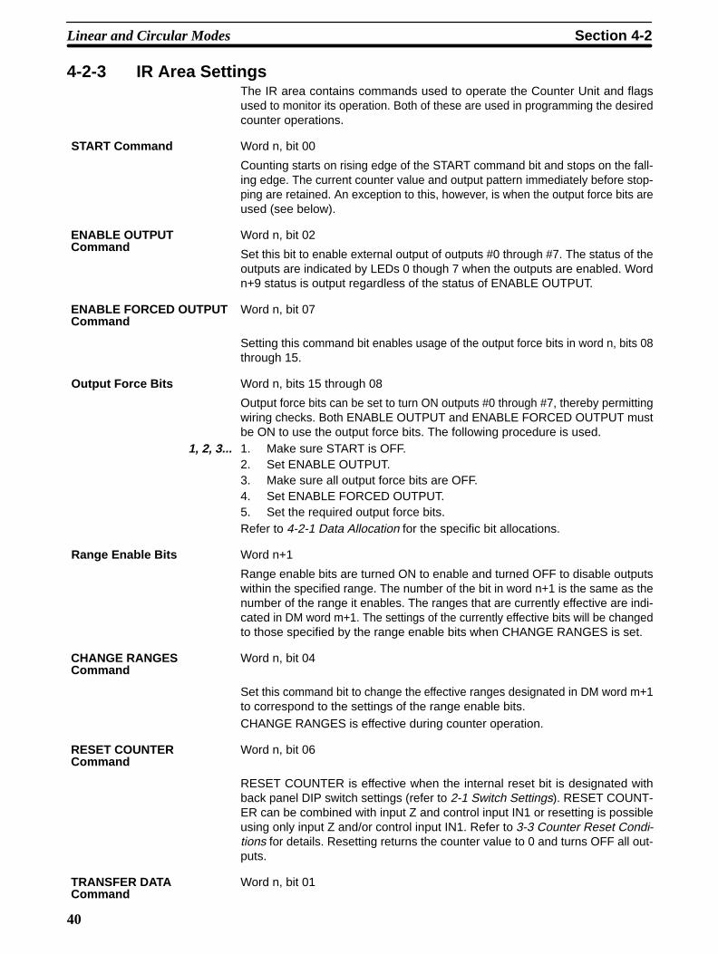
4-2-3 IR Area SettingsThe IR area contains commands used to operate the Counter Unit and flagsused to monitor its operation. Both of these are used in programming the desiredcounter operations.
START Command Word n, bit 00
Counting starts on rising edge of the START command bit and stops on the fall-ing edge. The current counter value and output pattern immediately before stop-ping are retained. An exception to this, however, is when the output force bits areused (see below).
Word n, bit 02
Set this bit to enable external output of outputs #0 through #7. The status of theoutputs are indicated by LEDs 0 though 7 when the outputs are enabled. Wordn+9 status is output regardless of the status of ENABLE OUTPUT.
Word n, bit 07
Setting this command bit enables usage of the output force bits in word n, bits 08through 15.
Output Force Bits Word n, bits 15 through 08
Output force bits can be set to turn ON outputs #0 through #7, thereby permittingwiring checks. Both ENABLE OUTPUT and ENABLE FORCED OUTPUT mustbe ON to use the output force bits. The following procedure is used.
1, 2, 3... 1. Make sure START is OFF.2. Set ENABLE OUTPUT.3. Make sure all output force bits are OFF.4. Set ENABLE FORCED OUTPUT.5. Set the required output force bits.Refer to 4-2-1 Data Allocation for the specific bit allocations.
Range Enable Bits Word n+1
Range enable bits are turned ON to enable and turned OFF to disable outputswithin the specified range. The number of the bit in word n+1 is the same as thenumber of the range it enables. The ranges that are currently effective are indi-cated in DM word m+1. The settings of the currently effective bits will be changedto those specified by the range enable bits when CHANGE RANGES is set.
Word n, bit 04
Set this command bit to change the effective ranges designated in DM word m+1to correspond to the settings of the range enable bits.CHANGE RANGES is effective during counter operation.
Word n, bit 06
RESET COUNTER is effective when the internal reset bit is designated withback panel DIP switch settings (refer to 2-1 Switch Settings). RESET COUNT-ER can be combined with input Z and control input IN1 or resetting is possibleusing only input Z and/or control input IN1. Refer to 3-3 Counter Reset Condi-tions for details. Resetting returns the counter value to 0 and turns OFF all out-puts.
Word n, bit 01
ENABLE OUTPUTCommand
ENABLE FORCED OUTPUTCommand
CHANGE RANGESCommand
RESET COUNTERCommand
TRANSFER DATACommand
Linear and Circular Modes Section 4-2

41
TRANSFER DATA can be set to change output ranges or, if the first word beingtransferred contains FF, it can be set to preset or change the current counter val-ue. Data in the proper format must be prepared in consecutive words in the PCthrough the PC program or the Programming Console. The parameters de-scribed below are required to transfer data. These are followed by explanationsof the data format used to prepare data in the PC data area and application ex-amples of TRANSFER DATA for transferring range parameters and counter val-ue. Data transfer is initiated on the rising edge of TRANSFER DATA and is com-pleted at the next I/O refresh. Completion can be confirmed with the transfercompleted flag, bit 04 of word n+4. Transfer should be executed only when theCounter Unit is not counting. Execution during counting may cause incorrectoutputs.
Word n+2
Indicates the first PC word from which data is to be transferred.
TRANSFER DATA Area Word n+3, bits 03 through 00
Set to between 0 and 4.
Specifies the PC data area from which data is to be transferred.
Specifications are as follows:
Setting Data area0 DM1 IR2 LR
3 HR4 AR
Note Use only the following words in the DM and IR areas: DM 0000 to DM 1999and IR 000 to IR 235. Although the C200HS provides larger areas, if anywords not within the specified ranges are used, an error will occur and anerror code of 34 will be output.
Number of Transfers Word n+3, bits 15 through 08
Set to between 1 and 3.
When changing range parameters, data for up to three ranges can be trans-ferred at the same time. When transferring the counter value, only one value canbe transferred at a time.
PC Data Format Six consecutive words are used as the source of a data transfer. Thesewords must all be in the same data area. If data is transferred for more thanone range, the six words for each following transfer must continue consecu-tively on from the last word for the first transfer. Bits 07 through 00 of the firstPC word actually designate either the range number for which data is to betransferred or, if the bits contain FF, they specify that a counter value is to betransferred.
If range parameters are being transferred, the remaining five words contain thelower limit, upper limit, and output pattern for the specified range in the sameformat that this data is contained in the DM area. If, for example, range #0 pa-rameters were being transferred, the second and third PC words would replaceparameters in DM words m+10 and m+11, i.e., the lower limit for range #0.
If a counter value is being transferred, the second and third PC words contain thecounter value in the same format that it is held in words n+6 and n+7, and the lastthree words are ignored. More efficient use of PC words is possible, however,when preparing more than one counter value for transfer. To do this, input FF into
TRANSFER DATABeginning Word Number
Linear and Circular Modes Section 4-2

42
the first and then every third word and input the counter values into the two wordsafter each word containing FF. The last counter value must be followed by threeunused words to satisfy the requirement for six words for the last counter value.This setup is shown on the next page for three counter values, with the first PCword indicated by k. Words k, k+3, and k+6 can then be designated individuallyto set the counter value as required.
PC Word Contents
k FF
k+1 and k+2 Counter value 1
k+3 FF
k+4 and k+5 Counter value 2
k+6 FF
k+7 and k+8 Counter value 3
k+9 through k+11 Ignored
The following example shows use of TRANSFER DATA to transfer the upperlimit, lower limit, and output pattern for three ranges. The system configura-tion consists of a Counter Unit (unit #0) on a C200H PC and an Input Unitallocated word 00. The Input Unit is connected to two switches: SW1, whichis programmed to START (00000), and SW2, which is programmed toTRANSFER DATA (00001).
Procedure1, 2, 3... 1. The range parameters are input into the DM area in a section not nor-
mally used by Special I/O Units, starting at DM word 1900 and runningthrough DM word 1905. Parameters for a second range are input start-ing at DM word 1906 and run through DM word 1911. A third range isinput into DM words 1912 through 1917.
2. The beginning word for transfer, the data area, and the number of trans-fers is set through the program, which is written to move the beginningword, 1900, into IR word 102 and the number of words and data area,03 for bits 15 through 08 and 00 for bits 07 through 00, into IR word 103.
Application Example 1:Transferring RangeParameters
Linear and Circular Modes Section 4-2

43
Program
MOV (21)
#0000
030
25315
MOV (21)
#1900
102
MOV (21)
#0300
103
DIFU (13) 03000
(SW2) 00001
(SW1) 00000
03000 10000
(START/STOP)
TRANSFER DATA SWITCH
Word 102: Beginningword
Word 103: Number of words and data area
TRANSFER DATA
DIFU (13) 03001
DIFD (14) 03002
10001
(Transfer completed flag)
10404
03000
03001 03002 03003
00000 00001 03003
03003
10000
10002
10006
START
OUTPUT ENABLE
RESET COUNTER
(SW1) (SW2)
First Cycle Flag
The following example shows use of TRANSFER DATA to transfer the count-er value. The system configuration consists of a Counter Unit (unit #1) on aC200H PC and three Input Units allocated words 00, 03, and 04. One InputUnit is connected to two switches: SW1, which is programmed to START(00000), and SW2, which is programmed to TRANSFER DATA (00001).Each of the other Input Units is connected to a rotary switch: the switch con-nected to the Input Unit allocated word 03 is used to input the rightmost four
Application Example 2:Transferring the CounterValue
Linear and Circular Modes Section 4-2
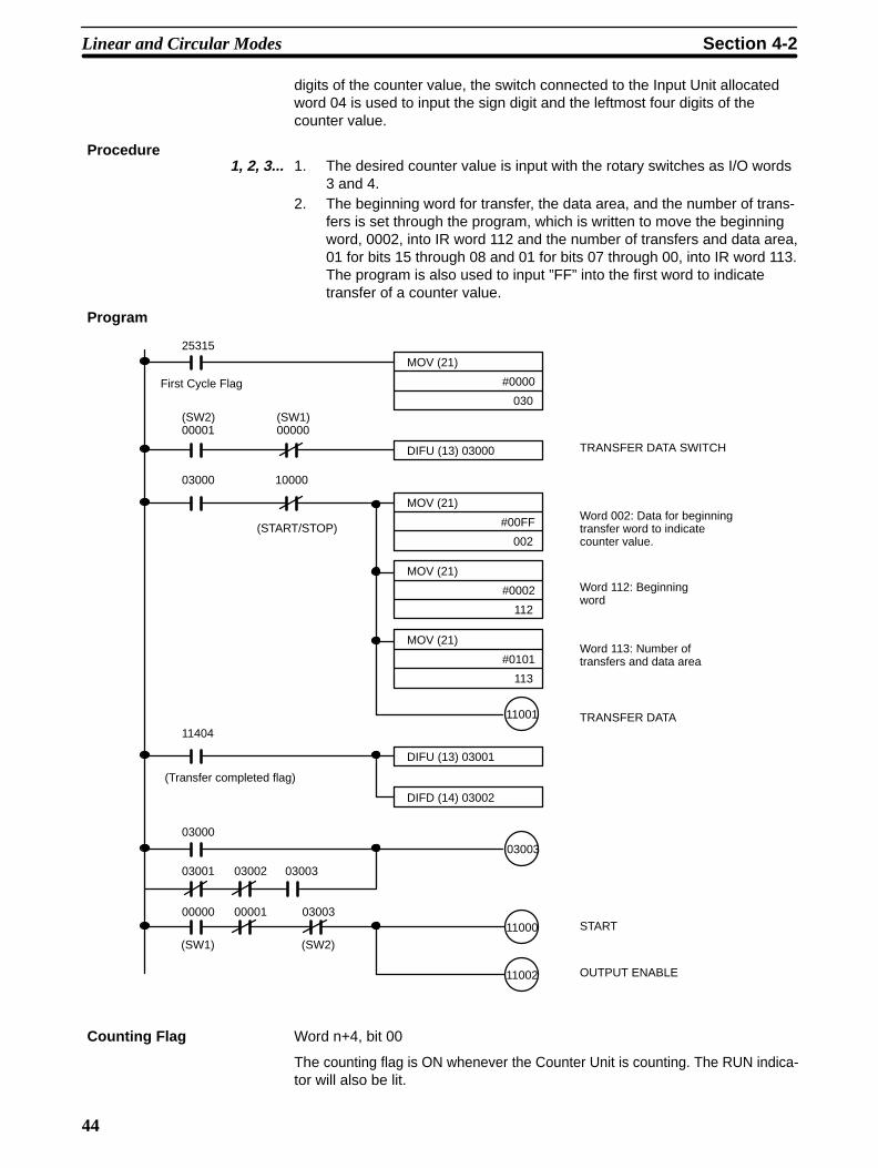
44
digits of the counter value, the switch connected to the Input Unit allocatedword 04 is used to input the sign digit and the leftmost four digits of thecounter value.
Procedure1, 2, 3... 1. The desired counter value is input with the rotary switches as I/O words
3 and 4.2. The beginning word for transfer, the data area, and the number of trans-
fers is set through the program, which is written to move the beginningword, 0002, into IR word 112 and the number of transfers and data area,01 for bits 15 through 08 and 01 for bits 07 through 00, into IR word 113.The program is also used to input ”FF” into the first word to indicatetransfer of a counter value.
Program
MOV (21)
#0000
030
25315
MOV (21)
#00FF
002
MOV (21)
#0002
112
DIFU (13) 03000
(SW2) 00001
(SW1) 00000
03000 10000
(START/STOP)
TRANSFER DATA SWITCH
Word 112: Beginningword
Word 113: Number of transfers and data area
TRANSFER DATA
DIFU (13) 03001
DIFD (14) 03002
11001
(Transfer completed flag)
11404
03000
03001 03002 03003
00000 00001 03003
03003
11000
11002
START
OUTPUT ENABLE
MOV (21)
#0101
113
Word 002: Data for beginningtransfer word to indicatecounter value.
(SW1) (SW2)
First Cycle Flag
Counting Flag Word n+4, bit 00
The counting flag is ON whenever the Counter Unit is counting. The RUN indica-tor will also be lit.
Linear and Circular Modes Section 4-2

45
Z Flag Word n+4, bit 01
The Z flag indicates the status of input Z. When the flag is ON, the input is high;when the flag is OFF, the input is low. This flag can be accessed during counting.
Note The Z flag may not turn ON if the Z phase pulse width is less than or equal tothe C200H/C200HS cycle time +3 ms.
IN1 Flag Word n+4, bit 02
The IN1 flag indicates the status of control input IN1. When the flag is ON, theinput is high; when the flag is OFF, the input is low. This flag can be accessedduring counting.
IN2 Flag Word n+4, bit 03
The IN2 flag indicates the status of control input IN2. When the flag is ON, theinput is high; when the flag is OFF, the input is low. This flag can be accessedduring counting.
Transfer Completed Flag Word n+4, bit 04
The transfer completed flag is inverted following completion of TRANSFERDATA.
Error Flag Word n+4, bit 05
The error flag is turned ON whenever an error has occurred. Information on thetype and location of the error is available in IR word n+5 upon execution of READERROR.
READ ERROR Command Word n, bit 05
READ ERROR can be set to access information on the error whenever the errorflag is ON. Error information is output to IR word n+5. If more then one error hasoccurred, information on other errors can be output to IR word n+5 by again set-ting READ ERROR. The next error will be output each time this bit is turned ON.
Error Location Word n+5, bit 07 through 00
The error location gives the rightmost two digits of the DM address, i.e., the wordnumber, where the data causing the error is stored.
Error Code Word n+5, bit 15 through 08
Error codes indicate the nature of the error and are given in Appendix A ErrorCode List.
Count Overflow Flag Word n+4, bit 06
The count overflow flag is turned ON when the counter value is greater than8,388,607 or less than –8,388,608. This flag turns OFF when the next operationis started.
Reset Flag Word n+4, bit 07
The reset flag turns ON for one PC cycle time after the Counter Unit is reset.
Current Counter Value Word n+6 and n+7
The current counter value is accessible in words n+6 and n+7 as 6 BCD digitswith a sign digit.
Range Flags Word n+8
The number of each bit in IR word n+8 corresponds to a range number. A rangeflag is ON whenever the current counter value is within the specified range.
Linear and Circular Modes Section 4-2

46
Output Flags Word n+9
The number of each bit in IR word n+9 corresponds to an output number. An out-put flag is ON whenever the specified output is ON. Output flags are turned ONregardless of the status of ENABLE OUTPUT.
4-2-4 Timing Chart
The following chart shows timing relationships between the command bits (inputbits) and output bits in linear and circular mode.
1 3 5 51
0
1
0
1
0
1
0
1
0
1
0
a b b a b
babbbaa
2 2
4
2
4 46
Start
Word n,bit 00
Counting flag
Word n + 4,bit 00
Internal outputs Word n + 9
ExternaloutputsOutputs toconnectorterminals
ENABLEOUTPUT
Word n, bit 02ENABLEFORCED OUTPUTWord n, bit 07
a: Normal outputsb: Forced outputs
1, 2, 3... 1. START is effective on the rising edge.
2. External outputs are prohibited when ENABLE OUTPUT is OFF.
3. The Counter Units stops counting on the falling edge of START. Status of internal and external outputs are retained.
4. The status of the output force bits is output when ENABLE FORCED OUTPUT is ON. All outputs are reset when ENABLE FORCED OUT-PUT goes OFF.
5. Setting START during counting returns all outputs to normal status, i.e.,makes ENABLE FORCED OUTPUT ineffective. The status of outputforce bits is then restored when STOP goes OFF.
6. ENABLE FORCED OUTPUT is ineffective while START is ON.
Linear and Circular Modes Section 4-2
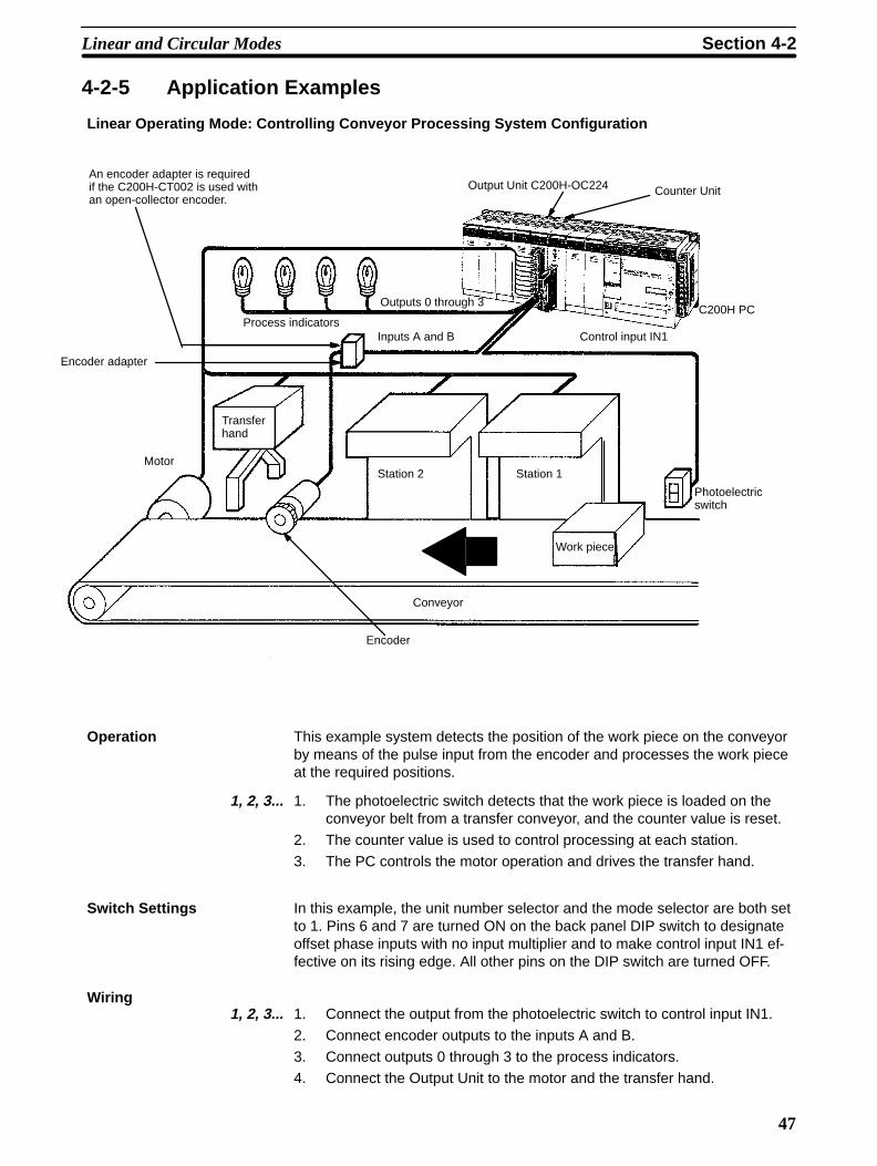
47
4-2-5 Application Examples
Linear Operating Mode: Controlling Conveyor Processing System Configuration
Output Unit C200H-OC224 Counter Unit
Control input IN1Inputs A and BProcess indicators
Station 2 Station 1
Work piece
Encoder
Conveyor
Motor
Transferhand
An encoder adapter is requiredif the C200H-CT002 is used withan open-collector encoder.
C200H PC
Encoder adapter
Outputs 0 through 3
Photoelectricswitch
Operation This example system detects the position of the work piece on the conveyorby means of the pulse input from the encoder and processes the work pieceat the required positions.
1, 2, 3... 1. The photoelectric switch detects that the work piece is loaded on theconveyor belt from a transfer conveyor, and the counter value is reset.
2. The counter value is used to control processing at each station.
3. The PC controls the motor operation and drives the transfer hand.
Switch Settings In this example, the unit number selector and the mode selector are both setto 1. Pins 6 and 7 are turned ON on the back panel DIP switch to designateoffset phase inputs with no input multiplier and to make control input IN1 ef-fective on its rising edge. All other pins on the DIP switch are turned OFF.
Wiring1, 2, 3... 1. Connect the output from the photoelectric switch to control input IN1.
2. Connect encoder outputs to the inputs A and B.
3. Connect outputs 0 through 3 to the process indicators.
4. Connect the Output Unit to the motor and the transfer hand.
Linear and Circular Modes Section 4-2

48
DM Area Settings
DM 1100
DM 1101
DM 1110
DM 1111
DM 1112
DM 1113
DM 1114
DM 1115
DM 1116
DM 1117
DM 1118
DM 1119
DM 1120
DM 1121
DM 1122
DM 1123
DM 1124
DM 1125
DM 1126
DM 1127
DM 1128
DM 1129
0 0 0
000
0 0 0
0000
0 0
0000
0 0 0
0 0
0000
00
0000
0 0
0 00
0 0 0 0
00
0000
0 0
0
000 0
0
0
0 0
1
1
1
1
1
1
2
2
2
2
2
3
3
4
5
5
5
5
7
8
8
8
8 6
9
9
9
F
Sets the mode to 1 (linear).Enables ranges #0, #1, #2, and #3.
Range #0 (work piece at station 1) Lower limit: 1000; upper limit: 1200 Output pattern specifies that output #0 be turned ON when the counter value is within range #0
Range #1 (work piece at station 2) Lower limit: 2500; upper limit: 2900 Output pattern specifies that outputs #1 and #8 be turned ON when the counter value is within range #1
Range #2 (work piece at transfer point) Lower limit: 5000; upper limit: 9500 Output pattern specifies that outputs #2 and #9 be turned ON when the counter value is within range #2.
Range #3 (work piece passed through transfer point) Lower limit: 9501; upper limit: 8,388,607 Output pattern specifies that outputs #3 and #10 be turned ON when the counter value is within range #3.
Linear and Circular Modes Section 4-2

49
Program
Processing is performed at station 1 when the current count-er value is within range #0.
Processing is performed at station 2 when the current count-er value is within range #1.
Transfer hand is operated when the current counter value iswithin range #2.
Completion process for one cycle is carried out when thecurrent counter value is within range #3
11000
11002
Station 1processing
Station 2processing
Controllingthe transferhand
Completionof one cycle
11909 11908
11909 11908
11909 11908
11909 11908
Start switchSTART and ENABLE OUTPUT are ON whilethe start switch is ON.
Internal outputs 11908 and 11909 are used to control position-dependent pro-cessing. Process indicators are turned ON and OFF directly through outputs #0through #3. Internal outputs are turned ON/OFF through ranges #0 through #3.These outputs indicate the position of the work piece, and required processing iscarried out accordingly.
Range flags can also be used for programming, as shown below.
11000
11002
Station 1processing
Station 2processing
Controllingthe transferhand
Completionof one cycle
11802
11803
Start switch
11801
11800
Range #0 flag
Range #1 flag
Range #2 flag
Range #3 flag
Linear and Circular Modes Section 4-2

50
Circular Operating Mode: Functioning as Mechanical Cam Switches System Configuration
Counter Unit
C200H PC
An encoder adapter is requiredif the C200H-CT002 is usedwith an open-collector encoder.
Motor
Encoder
Inputs A, B, and Z
Outputs #1, #6, and #7
Encoder adapter
Operation This example system uses the encoder to detect control timing for deviceslinked to a shaft driven by a motor. The system controls outputs according toshaft rotation.
Switch Settings In this example, the unit number selector is set to 1 and the mode selector isset to 2. Pins 2, 4, 6, and 8 are turned ON on the back panel DIP switch todesignate offset phase inputs with a x 4 input multiplier and to enable reset-ting on the rising edge of input Z or RESET COUNTER, whichever is set last(both must be ON to reset the Counter Unit). All other pins are turned OFF.
Wiring1, 2, 3... 1. Connect encoder outputs to inputs A, B, and Z.
2. Connect outputs #1, #6, and #7 to controllers for devices linked to theshaft.
Linear and Circular Modes Section 4-2

51
DM Area Settings
DM 1100
DM 1101
DM 1110
DM 1111
DM 1112
DM 1113
DM 1114
DM 1115
DM 1116
DM 1117
DM 1118
DM 1119
DM 1120
DM 1121
DM 1122
DM 1123
DM 1124
0 0 0
000
0 0 0
0000
1 0
0000
0 0 8
0 0
0000
00
0000
0 4
0 06
0 0 0 0
00
0000
0 C
2
1
1
0
0
0
4
0
2
0 0
3
0
1
2
3
7
Sets the mode to 1 (linear).Enables ranges #0, #1, #2, and #3.
Range #0 (work piece at station 1) Lower limit: 1000; upper limit: 1010 Output pattern specifies that output #7 be turned ON when the counter value is within range #0
Range #1 (work piece at station 2) Lower limit: 4300; upper limit: 200 (0 is spanned) Output pattern specifies that outputs #1 and #6 be turned ON when the counter value is within range #1
Range #2 (work piece at transfer point) Lower limit: 600; upper limit: 3100 Output pattern specifies that outputs #6 and #7 be turned ON when the counter value is within range #2.
DM 1102
DM 1103
4 9 9
000
9
0
Sets the maximum counter value to 4,999.(The counter values change as follows : 0,1,...4998, 4999, 0, 1,...)
Program
Start switch11000
11002
11006
11401
Input Z
Reset switch
11006
START and ENABLE OUTPUTare ON while the start switch isON.
The Counter Unit is reset onthe rising edge of the input Zimmediately after the counterreset switch is pressed.
Outputs #1, #6, and #7 are directly output from the Counter Unit.
Linear and Circular Modes Section 4-2

52
4-3 Preset ModeIn preset mode counter values are decremented (or incremented) according toany of the three types of input pulses. When the start signal is set, the countervalue begins from a specified, preset value (maximum: 8,388,607). Up to 20counter values can be preset. These presets can be updated from the PC six at atime by using TRANSFER DATA.
Eight outputs are available that can be output to the PC and/or externally, i.e.,directly to an external device. The first output (#0) turns ON when counting isstarted and turns OFF at a specified counter value. The next two outputs (#1 and#2) turn ON and OFF at specified counter values. The last four outputs (#4through #7, output #3 is not used in preset mode) turn ON for either a specifiedlength of time or indefinitely following the countdown. The counter values atwhich outputs turn ON and/or OFF cannot be changed during operation.
Although control input IN1 is supported as a reset input, control input IN2 andinput Z are not used.
Note that, because the counter is designed to count down in preset mode, theencoder input should be set accordingly.
The START command (word n, bit 00) is used to start and stop (i.e., as the startsignal) the Counter Unit when pin 4 on the back-panel DIP switch is turned OFF.Control input IN2 is used to start and stop the Counter Unit when pin 4 is ON.
4-3-1 Data Allocation
DM Area The DM area contains the user-input parameters that are to be set into theCounter Unit, including the operating mode and ON/OFF counter value. Thefirst DM word for each Counter Unit is indicated by m and equals 1,000 plus100 times the unit number.
Word Bit Function
m 07 through 00 Set to 0.
11 through 08 Operating mode (Here, 3: preset)
15 through 12 Set to 0.
m+1 15 through 00 OFF counter value for output #0, 7 digits
m+2 11 through 00
15 through 12 Set to 0.
m+3 15 through 00 ON counter value for output #1, 7 digits
m+4 11 through 00
15 through 12 Set to 0.
m+5 15 through 00 OFF counter value for output #1, 7 digits
m+6 11 through 00
15 through 12 Set to 0.
m+7 15 through 00 ON counter value for output #2, 7 digits
m+8 11 through 00
15 through 12 Set to 0.
m+9 15 through 00 OFF counter value for output #2, 7 digits
m+10 11 through 00
15 through 12 Set to 0.
m+11 15 through 00 ON time for outputs #4 through #7, 4 digits (unit: 0.01 s)Output will remain on until next the start signal if FFFF isinput.
m+12m+13
Not used.
m+14 15 through 00 Preset #0, 6 digits
Preset Mode Section 4-3

53
Word FunctionBit
m+15 11 through 00
15 through 12 Output pattern #0 (for preset #0);Bit 12: output #4Bit 13: output #5Bit 14: output #6Bit 15: output #7
Word Function
m+16m+17
m+18m+19
m+20m+21
m+22m+23
m+24m+25
m+26m+27
m+28m+29
m+30m+31
m+32m+33
m+34m+35
Preset #1 and output pattern #1
Preset #2 and output pattern #2
Preset #3 and output pattern #3
Preset #4 and output pattern #4
Preset #5 and output pattern #5
Preset #6 and output pattern #6
Preset #7 and output pattern #7
Preset #8 and output pattern #8
Preset #9 and output pattern #9
Preset #10 and output pattern #10
Word Function
m+36m+37
m+38m+39
m+40m+41
m+42m+43
m+44m+45
m+46m+47
m+48m+49
m+50m+51
m+52m+53
m+54 tom+99
Preset #11 and output pattern #11
Preset #12 and output pattern #12
Preset #13 and output pattern #13
Preset #14 and output pattern #14
Preset #15 and output pattern #15
Preset #16 and output pattern #16
Preset #17 and output pattern #17
Preset #18 and output pattern #18
Preset #19 and output pattern #19
Not used.
IR Area The IR area contains commands and status information. Inputs and outputsare given in reference to the PC, i.e., output data is sent from the PC to theCounter Unit; input data, from the Counter Unit to the PC. The first IR wordfor each Counter Unit is indicated by n and equals 100 plus 10 times the unitnumber.
Preset Mode Section 4-3

54
Word Bit Function
n 00 START command (The START command is effective onlywhen pin 4 on the back-panel DIP switch is turned OFF. If pin4 is ON, control input IN2 is used to start and stop theCounter Unit.)
01 TRANSFER DATA command
02 ENABLE OUTPUT command
03 Not used.
04 CHANGE PRESET command
05 READ ERROR command
06 RESET COUNTER command
07 ENABLE FORCED OUTPUT command
08 Output #0 force bit
09 Output #1 force bit
10 Output #2 force bit
11 Output #3 force bit
12 Output #4 force bit
13 Output #5 force bit
14 Output #6 force bit
15 Output #7 force bit
n+1 07−04 Not used.
15−08 Preset number, 2 digits, between 00 and 19
n+2 15−00 TRANSFER DATA beginning word number, 4 digits
n+3 03−00 TRANSFER DATA data area, 0 through 4
07−04 Not used. (Set to 0.)
15−08 Number of transfers, 1 through 3
Outputs
Preset Mode Section 4-3
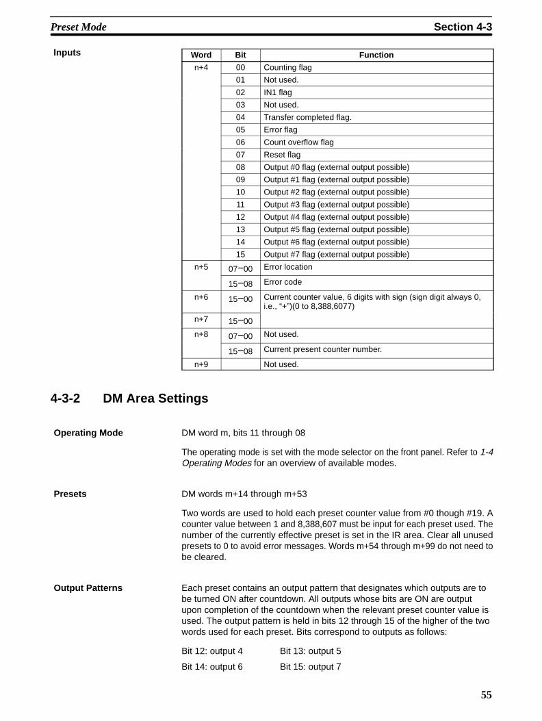
55
Word Bit Function
n+4 00 Counting flag
01 Not used.
02 IN1 flag
03 Not used.
04 Transfer completed flag.
05 Error flag
06 Count overflow flag
07 Reset flag
08 Output #0 flag (external output possible)
09 Output #1 flag (external output possible)
10 Output #2 flag (external output possible)
11 Output #3 flag (external output possible)
12 Output #4 flag (external output possible)
13 Output #5 flag (external output possible)
14 Output #6 flag (external output possible)
15 Output #7 flag (external output possible)
n+5 07−00 Error location
15−08 Error code
n+6 15−00 Current counter value, 6 digits with sign (sign digit always 0,i.e., “+”)(0 to 8,388,6077)
n+7 15−00
n+8 07−00 Not used.
15−08 Current present counter number.
n+9 Not used.
4-3-2 DM Area Settings
Operating Mode DM word m, bits 11 through 08
The operating mode is set with the mode selector on the front panel. Refer to 1-4Operating Modes for an overview of available modes.
Presets DM words m+14 through m+53
Two words are used to hold each preset counter value from #0 though #19. Acounter value between 1 and 8,388,607 must be input for each preset used. Thenumber of the currently effective preset is set in the IR area. Clear all unusedpresets to 0 to avoid error messages. Words m+54 through m+99 do not need tobe cleared.
Output Patterns Each preset contains an output pattern that designates which outputs are tobe turned ON after countdown. All outputs whose bits are ON are outputupon completion of the countdown when the relevant preset counter value isused. The output pattern is held in bits 12 through 15 of the higher of the twowords used for each preset. Bits correspond to outputs as follows:
Bit 12: output 4 Bit 13: output 5
Bit 14: output 6 Bit 15: output 7
Inputs
Preset Mode Section 4-3
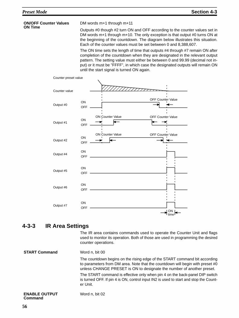
56
DM words m+1 through m+11
Outputs #0 though #2 turn ON and OFF according to the counter values set inDM words m+1 through m+10. The only exception is that output #0 turns ON atthe beginning of the countdown. The diagram below illustrates this situation.Each of the counter values must be set between 0 and 8,388,607.
The ON time sets the length of time that outputs #4 through #7 remain ON aftercompletion of the countdown when they are designated in the relevant outputpattern. The setting value must either be between 0 and 99.99 (decimal not in-put) or it must be ”FFFF”, in which case the designated outputs will remain ONuntil the start signal is turned ON again.
ÉÉÉÉÉÉÉÉÉÉÉÉÉÉÉÉÉÉÉÉÉÉÉÉ
Counter preset value
Counter value
Output #0ON
OFF
Output #1ON
OFF
Output #2ON
OFF
Output #4ON
OFF
Output #5ON
OFF
Output #6ON
OFF
Output #7ON
OFFON time
OFF Counter Value
OFF Counter Value
OFF Counter Value
ON Counter Value
ON Counter Value
4-3-3 IR Area SettingsThe IR area contains commands used to operate the Counter Unit and flagsused to monitor its operation. Both of those are used in programming the desiredcounter operations.
START Command Word n, bit 00
The countdown begins on the rising edge of the START command bit accordingto parameters from DM area. Note that the countdown will begin with preset #0unless CHANGE PRESET is ON to designate the number of another preset.
The START command is effective only when pin 4 on the back-panel DIP switchis turned OFF. If pin 4 is ON, control input IN2 is used to start and stop the Count-er Unit.
Word n, bit 02
ON/OFF Counter Values ON Time
ENABLE OUTPUTCommand
Preset Mode Section 4-3

57
Set this bit to enable external output of outputs #0 though #7. The status of theoutputs is shown on indicators 0 though 7 when outputs are enabled. Word n+9status is output regardless of the condition of ENABLE OUTPUT.
Word n, bit 07
Setting this command bit enables usage of the output force bits in word n (bits 08through 15).
Output Force Bits Word n, bits 15 through 08
Output force bits can be set to turn ON outputs #0 through #7, thereby permittingwiring checks. Both the ENABLE OUTPUT command bit and the ENABLEFORCED OUTPUT command bit must be ON to use the output force bits. Thefollowing procedure is used.
1, 2, 3... 1. Make sure the start signal is OFF.2. Set ENABLE OUTPUT.3. Make sure all output force bits are OFF.4. Set ENABLE FORCED OUTPUT.5. Set the required output force bits.Refer to 4-3-1 Data Allocation for the specific bit allocations.
CHANGE PRESET Word n, bit 04
CHANGE PRESET is set to designate any preset other than #0. If CHANGEPRESET is OFF when the start signal is set, the countdown will begin from thevalue designated by preset #0, regardless of the contents of the preset desig-nated by the preset number.
Preset Number Word n+1, bits 15 through 08
The preset number is set to designate a preset counter value other then preset#0. The number set in bits 15 through 08 is effective only when CHANGE PRE-SET is turned ON before the start signal is turned ON.
Word n, bit 06
RESET COUNTER is effective when the internal reset bit is designated withback panel DIP switch settings (Refer to 2-1 Switch Settings). RESET COUNT-ER can be combined with control input IN1 or resetting is possible using onlycontrol input IN1. Refer to 3-3 Counter Reset Conditions for details. Resettingreturns the counter value to 0 and turns OFF all outputs.
Word n, bit 01
TRANSFER DATA can be set to transfer up to 6 preset counter values to replaceany of presets #0 through #19. The new presets can then be used for count-down. Data in the proper format must be prepared in consecutive words in thePC through the PC program or the Programming Console. The parameters de-scribed below are required to transfer data. These are followed by explanationsof the data format used to prepare data in the PC data area. Data transfer is initi-ated on the rising edge of TRANSFER DATA and is completed at the next I/Orefresh. Completion can be confirmed with the transfer completed flag, bit 04 ofword n+4. Transfer should be executed only when the Counter Unit is not count-ing. Execution during counting may cause incorrect outputs.
Word n+2
Indicates the first PC word from which data is to be transferred.
TRANSFER DATA Area Word n+3, bits 03 through 00
ENABLE FORCED OUTPUTCommand
PRESET COUNTERCommand
TRANSFER DATACommand
TRANSFER DATABeginning Word Number
Preset Mode Section 4-3

58
Set to between 0 and 4.Indicates the PC data area from which data is to be transferred. Indications areas follows:
Setting Data area
0 DM
1 I/O
2 LR
3 HR
4 AR
Note Use only the following words in the DM and IR areas: DM 0000 to DM 1999and IR 000 to IR 235. Although the C200HS provides larger areas, if anywords not within the specified ranges are used, an error will occur and anerror code of 34 will be output.
Number of Transfers Word n+3, bits 15–08
Set to between 1 and 6.Counter values can be transferred for up to 6 presets at the same time. To trans-fer more the 6, TRANSFER DATA must be executed a second time with differentparameters.
PC Data Format Three consecutive words are used as the source of data transfer for eachpreset that is being transferred. These words must all be in the same dataarea. If data is transferred for more than one preset, the three words for eachfollowing transfer must continue consecutively on from the last word for thefirst transfer. The first word designates the number of the preset whose valueis contained in the following two words. The last two words contain the presetcounter value and output pattern in the same format as that used in DM forthe normal presets. The numbers of the presets being transferred need notbe consecutive.
Counting Flag Word n+4, bit 00
The counting flag is ON whenever the Counter Unit is counting. This flag will re-main ON from when the start signal resets the counter to the preset value untilthe current counter value reaches 0. Even if external outputs #4 to #7 remain ONafter the current counter value reaches 0, the counting flag will be OFF. The RUNindicator will be lit when the counting flag is ON.
IN1 Flag Word n+4, bit 02
The IN1 flag indicates the status of control input IN1. When the flag is ON, theinput is high; when the flag is OFF, the input is low. This flag can be accessedduring counting.
Transfer Completed Flag Word n+4, bit 04
The transfer completed flag is inverted following completion of TRANSFERDATA.
Error Flag Word n+4, bit 05
The error flag is turned ON whenever an error has occurred. Information on thetype and location of the error is available in IR word n+5 upon execution of READERROR.
READ ERROR Command Word n, bit 05
READ ERROR can be set to access information on the error whenever the errorflag is ON. Error information is output to IR word n+5. If more than one error has
Preset Mode Section 4-3

59
occurred, information on other errors can be output to IR word n+5 by again set-ting READ ERROR.
Error Location Word n+5, bit 07 through 00
The error location gives the rightmost two digits of the DM address, i.e., the bitnumber, where the data causing the error is stored.
Error Code Word n+5, bit 15 through 08
Error codes indicate the nature of the error and are given in Appendix A ErrorCode List.
Count Overflow Flag Word n+4, bit 06
The count overflow flag is turned ON when the counter value is incrementedpassed 8,388,607. This flag turns OFF when the next counting operation isstarted.
Reset Flag Word n+4, bit 07
The reset flag turns ON for one PC cycle time after the Counter Unit is reset.
Current Counter Value Word n+6 and n+7
The current counter value is accessible in words n+6 and n+7 as 6 BCD digitswith a sign digit. In preset mode, the sign digit is always 0 (+).
Output Flags Word n+4 bits, 15 through 08
Output flag bits are ON whenever the corresponding output is ON. Output flagsturn ON regardless of the status of ENABLE OUTPUT (word n, bit 02). Refer to4-3-1 Data Allocation for specific flag bits.
Preset Mode Section 4-3
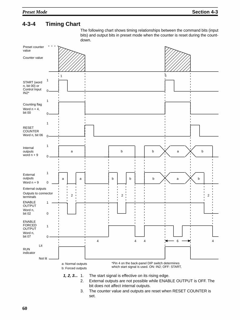
60
4-3-4 Timing ChartThe following chart shows timing relationships between the command bits (inputbits) and output bits in preset mode when the counter is reset during the count-down.
5
5
1
0
1
0
1
0
1
0
1
0
b b a b
babba
2 2
4
2
4 46
START (wordn, bit 00) orControl InputIN2*
Counting flagWord n + 4,bit 00
Internal outputs word n + 9
ExternaloutputsWord n + 9
ENABLEOUTPUTWord n, bit 02
ENABLEFORCEDOUTPUTWord n, bit 07
a b
a
ÉÉÉÉÉÉÉÉÉÉÉÉÉÉÉÉÉÉÉÉÉÉÉÉÉ
ÉÉÉÉÉÉÉÉÉÉÉÉÉÉÉÉÉÉÉÉÉÉÉÉÉ
1
0
1
0
RESETCOUNTERWord n, bit 06
4
Preset countervalue
Counter value
External outputs
Outputs to connectorterminals
a: Normal outputsb: Forced outputs
Lit
Not lit
RUN indicator
*Pin 4 on the back-panel DIP switch determineswhich start signal is used. ON: IN2; OFF: START,
1
1, 2, 3... 1. The start signal is effective on its rising edge.2. External outputs are not possible while ENABLE OUTPUT is OFF. The
bit does not affect internal outputs.3. The counter value and outputs are reset when RESET COUNTER is
set.
Preset Mode Section 4-3

61
4. Forced outputs are possible only when the counting flag is OFF.
5. Normal operation is returned to when the start signal is set during forcedoutput.
6. Forced outputs becomes inoperative during normal operation.
7. When RESET COUNTER is set during a forced output, the external output is momentarily turned OFF, then restored to the status designated by the relevant force bit.
4-3-5 Application Example
Measuring and Cutting Rod System Configuration
Counter Unit
C200H PC
Output #4
Cutter
Output #0
Output #1
Output #2
Motor Controller
Output
Motor ON
High/lowspeed
Brake
Motor
Encoder
Bobbin
An encoder adapter is requiredif the C200H-CT002 is usedwith an open-collector encoder.
Inputs A and B Outputs #0 through #2, and #4
Encoder adapter
Operation A specific length wire rod is fed in and cut using the following controlling pro-cedure.
1, 2, 3... 1. The motor is started at a low speed and the brake is turned OFF.
2. The motor speed is increased.
3. The motor speed is decreased just before the designated position.
4. The motor is stopped, taking the distance the motor moves by inertia into consideration.
5. The brake is turned ON immediately before the designated position.
6. The cutter is activated at the designated position.
Preset Mode Section 4-3

62
ÉÉÉÉÉÉÉÉÉÉÉÉÉÉÉÉÉÉÉÉÉÉÉÉÉÉÉÉÉÉÉÉÉON
OFF
Highspeed
Lowspeed
ON
OFF
ON
OFF
ParameterPresent counter valueA
BCD
ET
Setting (ms)10,000100
1502000
50500
A
C
T
B
E
Current counter value
Counter preset value
Motor drive (Output #0)
High/Low speed (Output #1)
Brake (Output #2)
Cutter (Output #4)
Setting example
Switch Settings In this example, the unit number switch is set to 1 and the mode switch is setto 3. Pins 3 and 8 are turned ON on the back-panel DIP switch to designateoffset phase inputs with a x2 input multiplier and to enable RESET COUNT-ER. All other pins on the DIP switch are turned OFF.
Wiring1, 2, 3... 1. Connect encoder outputs to inputs A and B.
2. Connect outputs #0, #1, and #2 to the motor controller inputs as follows:#0: motor start switch; #1: high/low speed switch; #2: brake sig-
nal.
3. Connect output #4 to the input terminal of the cutter driver.
DM Area Settings
DM 1100
DM 1101
DM 1102
DM 1103
DM 1104
DM 1105
DM 1106
DM 1107
DM 1108
DM 1109
DM 1110
DM 1111
DM 1112
DM 1113
DM 1114
3 0 0
0010
0 0
0510
0 0 0
0 0
0000
00
0000
0 5
0 00
0 0 5 0
––
––––
0 0
0
0
0
0
0
0
0
0
0 0
2
0
–
0
–
DM 1115 1 00 1
Sets mode no. 3.
A = 100
B = 150
C = 200
D = 0
E = 50
T = 500 ms
Preset = 10000
Output #4 only
Preset Mode Section 4-3

63
Program
11006
RESET COUNTER
25315MOV (21)
#0000
111
11004
(ON for one cycle)
11002
11000
DIFD (14) 03000
03001
1100003000
03001
Output #4
START
25313 (usually ON)
Counter and outputs reset.
Preset number set (here, to00). Programming within thedotted line can be omitted if thepreset number is 00.
ENABLE OUTPUT turned ON.
START
Completion of cutter opera-tion detected (OFF).
Outputs indicates completionof cutting.
4-4 Gate, Latch, and Sampling ModesIn gate, latch, and sampling modes counter values are incremented and decre-mented while the count signal is ON and according to any of the three types ofinput pulses. All three modes permit counting between –8,388,608 and8,388,607. All modes but cumulative gate mode use control input IN1 as thecount (start) signal. The cumulative gate mode uses control input IN1 as the re-set signal and control input IN2 as the count (start) signal; latch mode uses con-trol input IN2 as the latch signal. None of these modes support external outputs.Control inputs can be designated to originate in IR bits.
Gate, Latch, and Sampling Modes Section 4-4
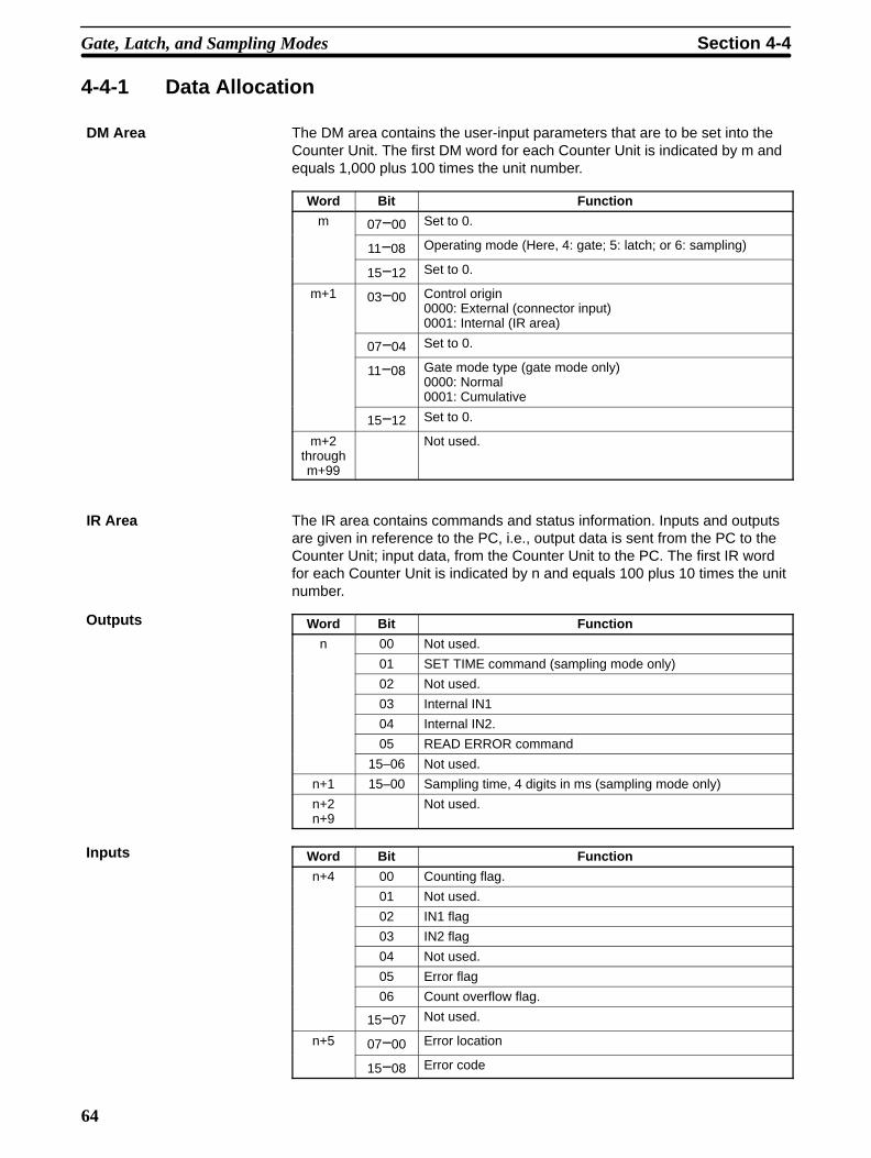
64
4-4-1 Data Allocation
DM Area The DM area contains the user-input parameters that are to be set into theCounter Unit. The first DM word for each Counter Unit is indicated by m andequals 1,000 plus 100 times the unit number.
Word Bit Function
m 07−00 Set to 0.
11−08 Operating mode (Here, 4: gate; 5: latch; or 6: sampling)
15−12 Set to 0.
m+1 03−00 Control origin0000: External (connector input)0001: Internal (IR area)
07−04 Set to 0.
11−08 Gate mode type (gate mode only)0000: Normal0001: Cumulative
15−12 Set to 0.
m+2throughm+99
Not used.
IR Area The IR area contains commands and status information. Inputs and outputsare given in reference to the PC, i.e., output data is sent from the PC to theCounter Unit; input data, from the Counter Unit to the PC. The first IR wordfor each Counter Unit is indicated by n and equals 100 plus 10 times the unitnumber.
Word Bit Function
n 00 Not used.
01 SET TIME command (sampling mode only)
02 Not used.
03 Internal IN1
04 Internal IN2.
05 READ ERROR command
15–06 Not used.
n+1 15–00 Sampling time, 4 digits in ms (sampling mode only)
n+2n+9
Not used.
Word Bit Function
n+4 00 Counting flag.
01 Not used.
02 IN1 flag
03 IN2 flag
04 Not used.
05 Error flag
06 Count overflow flag.
15−07 Not used.
n+5 07−00 Error location
15−08 Error code
Outputs
Inputs
Gate, Latch, and Sampling Modes Section 4-4

65
Word FunctionBit
n+6 15−00 Current counter value, 6 digits with sign (–8,388,608 to8 388 607)
n+7 15−008,388,607)
n+8n+9
Not used
Note 1. The RUN indicator will be lit whenever the counting flag (word n+4, bit 00)is ON.
2. The external control inputs IN1 and IN2 must be ON for at least as longas the PC’s cycle time to ensure that they can be accurately read from thePC.
4-4-2 DM Area SettingsOperating Mode DM word m, bits 11 through 08
The operating mode is set with the mode switch on the front panel. Refer to 1-4Operating Modes for an overview of available modes.
Control Origin DM word m+1, bits 03 through 10
Control inputs (start, reset, and latch) can be designated as originating from theconnector (control inputs IN1 and IN2) or from the IR area (internal IN1 and IN2).Designations are as follows:0: External (connector input)1: Internal (IR area)
DM word m+1, bits 11 through 08
The gate mode type determines the use of control inputs IN1 and IN2. Refer to1-4 Operating Modes for details. Designations are as follows:0000: Normal0001: Cumulative
4-4-3 IR Area SettingsWord n, bit 01
SET TIME is turned ON to use the sampling time held in word n+1. The new sam-pling time is effective on the rising edge of SET TIME, unless the counting flag inON, in which case the new sampling time is effective after completion of the cur-rent counting operation.
Word n+1
Set to between 0010 and 9999 in ms.The sampling time designates the time that pulses will be counted following con-trol input IN1.
Word n, bit 03 or external connector
Word n, bit 04 or external connector
The setting of the control origin, DM word m+1 bits 03 through 00, determineswhether external signals or IR bits are used as the start, latch, and gate signals.In cumulative gate mode (CT002 only), IN1 is the reset signal and IN2 the countsignal. Pulses are counted while IN2 is ON. In normal gate mode, IN1 is thecount signal and pulses are counted while it is ON.
Gate Mode Type (Gate Mode Only)
SET TIME Command(Sampling Mode Only)
Sampling T ime (Sampling Mode Only)
Control Inputs Internal IN1or Control Input IN1
Internal IN2 or Control Input IN2
Gate, Latch, and Sampling Modes Section 4-4

66
In sampling mode, IN1 is the count signal.
In latch mode, IN1 is the count signal and IN2 the latch signal.
Error Flag Word n+4, bit 05
The error flag is turned ON whenever an error has occurred. Information on thetype and location of the error is available in IR word n+5 upon execution of READERROR.
READ ERROR Command Word n, bit 05
READ ERROR can be set to access information on the error whenever the errorflag is ON. Error information is output to IR word n+5. If more than one error hasoccurred, information on other errors can be output to IR word n+5 by again set-ting READ ERROR.
Error Location Word n+5, bit 07 through 00
The error location gives the rightmost two digits of the DM address, i.e., the bitnumber, where the data causing the error is stored.
Error Code Word n+5, bit 15 through 08
Error codes indicate the nature of the error and are given in Appendix A ErrorCode List.
Counting Flag Word n+4, bit 00
The counting flag is ON whenever the Counter Unit is counting.
IN1 Flag Word n+4, bit 02
The IN1 flag indicates the status of control input IN1. When the flag is ON, theinput is high; when the flag is OFF, the input is low. This flag can be accessedduring counting.
IN2 Flag Word n+4, bit 03
The IN2 flag indicates the status of control input IN2. When the flag is ON, theinput is high; when the flag is OFF, the input is low. This flag can be accessedduring counting.
Count Overflow Flag Word n+4, bit 06
The count overflow flag is turned ON when the counter value is incrementedpassed 8,388,607. This flag turns OFF when the next operation is started.
Current Counter Value Word n+6 and n+7
Between –8,388,608 and 8,388,607
The current counter value is accessible in words n+6 and n+7 as 6 BCD digitswith a sign digit.
4-4-4 Timing ChartsThe following four charts show the relationship between the input and output bitsin the two types of gate mode, the latch mode, and the sampling mode.
Gate, Latch, and Sampling Modes Section 4-4
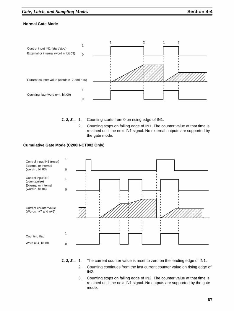
67
Normal Gate Mode
ÉÉÉÉÉÉÉÉÉÉÉÉÉÉÉÉÉÉÉÉÉÉÉÉÉÉÉÉÉÉÉÉÉÉÉÉÉÉÉÉ
ÉÉÉÉÉÉÉÉÉÉÉÉÉÉÉÉ
1
0
1
0
1 2 1 2
Control input IN1 (start/stop)
External or internal (word n, bit 03)
Current counter value (words n+7 and n+6)
Counting flag (word n+4, bit 00)
1, 2, 3... 1. Counting starts from 0 on rising edge of IN1.
2. Counting stops on falling edge of IN1. The counter value at that time isretained until the next IN1 signal. No external outputs are supported bythe gate mode.
Cumulative Gate Mode (C200H-CT002 Only)
ÉÉÉÉÉÉÉÉÉÉÉÉÉÉÉÉÉÉÉÉÉÉÉÉÉÉÉÉÉÉÉÉÉÉÉÉÉÉÉÉ
ÉÉÉÉÉÉ
ÉÉÉÉÉÉÉÉÉÉÉÉÉÉÉÉÉÉÉÉÉÉÉÉ
1
0
1
0
1
0
Control input IN1 (reset)External or internal (word n, bit 03)
Control input IN2 (count pulse)External or internal (word n, bit 04)
Current counter value(Words n+7 and n+6)
Counting flag
Word n+4, bit 00
1, 2, 3... 1. The current counter value is reset to zero on the leading edge of IN1.
2. Counting continues from the last current counter value on rising edge ofIN2.
3. Counting stops on falling edge of IN2. The counter value at that time isretained until the next IN1 signal. No outputs are supported by the gatemode.
Gate, Latch, and Sampling Modes Section 4-4

68
Latch Mode
ÉÉÉÉÉÉÉÉÉÉÉÉÉÉÉÉÉÉÉÉÉÉÉÉÉÉÉÉÉÉÉÉÉÉÉÉÉÉÉÉÉÉÉÉÉÉÉÉÉÉÉÉÉÉÉÉÉÉÉÉÉÉÉÉÉÉÉÉÉÉÉÉÉÉÉÉÉÉÉÉÉÉÉÉ
ÉÉÉÉÉÉÉÉÉÉÉÉÉÉÉÉÉÉ
ÉÉÉÉÉÉÉÉÉÉÉÉÉÉÉÉÉÉÉÉÉÉÉÉÉÉÉÉÉÉ
ÉÉÉÉÉÉÉÉÉÉÉÉÉÉÉÉÉÉÉÉ
ÉÉÉÉÉÉÉÉÉÉÉÉÉÉÉÉÉÉ
1 4
2 3
1
0
1
0
1
0
Control input IN1 (start)
External or internal (word, bit 03)
Control input IN2 (latchsignal)
External or internal (word n, bit 04)
Internal (actual) counter value
Current counter value (words n+7 and n+6)
Counting flag(word n + 4, bit 00)
1, 2, 3... 1. Counting starts from 0 on the rising edge of IN1.2. The current counter value is latched (frozen) on the rising edge of IN2
(latch signal) and latched value is maintained until the next IN2 or IN1signal.
3. The internal counter value continues to be incremented and decrem-ented without being affected by the latch signal.
4. Both the internal current counter values are reset to 0 on the next IN1signal. No outputs are supported by the latch mode.
Gate, Latch, and Sampling Modes Section 4-4

69
Sampling Mode
ÉÉÉÉÉÉÉÉÉÉÉÉÉÉÉÉÉÉÉÉÉÉÉÉÉÉÉÉÉÉÉÉÉÉÉÉÉÉÉÉÉÉÉÉÉÉÉÉÉÉ
ÉÉÉÉÉÉÉÉÉÉÉÉÉÉÉÉÉÉÉÉÉÉÉÉÉÉÉÉÉÉÉÉÉÉÉÉÉÉÉÉÉÉÉÉ
2 3
T1 T2
1 3
T1 T2
Sampling timeWord n + 1
1
0
1
0
1
0
Control input IN1 (start)
External or internal(word n, bit 03)
Sampling time(word n+1)
SET TIME(word n, bit 1)
Counting flag
(word n+4, bit 00)
Current counter value (words n+7 and n+6)
1, 2, 3... 1. The sampling time is set from word n+1 before starting.
2. Counting starts from 0 on the rising edge of IN1. After expiration of thesampling time, the count stops and the counter value is retained untilthe next IN1 signal.
3. When SET DATA is turned ON while the counting flag is ON, the newsampling time is set after completion of the counting operation and usedfor the next counting operation. No external outputs are supported bythe sampling mode.
Note Set up the system so that control input IN1 turns ON after setting the sam-pling time has been completed. The following is an example for internal con-trol input 1.
Scan
Sampling time
Setting of thesampling time
Internal controlinput 1
Counting flag
Current count value
TSampling time
T
ONOFF
ONOFF
ONOFF
Scan Scan
Gate, Latch, and Sampling Modes Section 4-4

70
4-4-5 Application Examples
Gate Mode: Measuring Product Length System Configuration
Counter Unit
C200H PCControl Input IN1
Inputs A and B
Encoder
An encoder adapteris required if theC200H-CT002 isused with an open-collector encoder.
Product
Photoelectric switch fordetecting product
Encoder adapter
Operation This example system counts encoder inputs while the photoelectric switch isON to measure the lengths of products on a conveyor. The PC uses the re-sulting length measurements to determine if product lengths are within stan-dards.
Switch Settings In this example, the unit number selector is set to and 1 and the mode selec-tor is set to 4.
All pins are turned OFF on the back panel DIP switch to designate offset phaseinputs with no input multiplier.
Wiring1, 2, 3... 1. Connect encoder outputs to inputs A and B.
2. Connect the photoelectric switch output to control input IN1.
DM Area Settings
DM 1100 0 4 0 00000DM 1101
Sets the mode to 4 (gate). Designates use of control IN1from the connector (not the inter-nal IN1) and normal gate mode(not cumulative).
Gate, Latch, and Sampling Modes Section 4-4
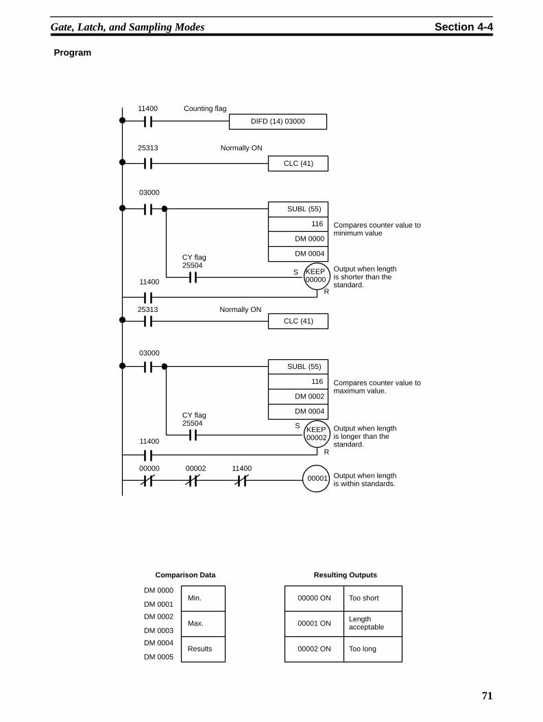
71
Program
11400
DIFD (14) 03000
25313
03000
CLC (41)
SUBL (55)
116
DM 0000
DM 0004CY flag25504
S KEEP00000
R11400
25313
03000
CLC (41)
SUBL (55)
116
DM 0002
DM 0004CY flag25504 S KEEP
00002
R
11400
1140000000 0000200001
Counting flag
Normally ON
Normally ON
Compares counter value tominimum value
Output when lengthis shorter than thestandard.
Compares counter value tomaximum value.
Output when lengthis longer than thestandard.
Output when lengthis within standards.
Comparison Data
DM 0000
DM 0001
DM 0002
DM 0003
DM 0004
DM 0005
Min.
Max.
Results
00000 ON
00001 ON
00002 ON
Too short
Length acceptable
Too long
Resulting Outputs
Gate, Latch, and Sampling Modes Section 4-4

72
Latch Mode: Monitoring Quantity at a Processing Station System Configuration
Processing station
Flow Flow
Transistor Output UnitC200H-OD211
C200H PC
An encoder adapter is requiredif the C200H-CT002 is usedwith an open-collector encoder
Photoelectric switch for detecting fed workpieces (in-crement, input A)
Indicator
Photoelectric switch fordetecting dischargedworkpieces (decre-ment, input B)
Control switch(control input IN1)
Latch switch(Control input IN2)
Encoder adapter
Operation This example system monitors the number of work pieces in the processingstation and displays the currently latched number on a seven-segment indi-cator.
Sign 106 105 104 103 102 101 100
0 1 2 3 4 5 6 7
11–8
7–4
3–0
Strobe signal
Sign, 105, 103, 101, data
106, 104, 102, 100 data
Transistor Output Unit
101, 100 103, 102 105, 104 107, 106 101, 100Output data
Strobe 0
Strobe 1
Strobe 2
Strobe 3
PC cycle time
Gate, Latch, and Sampling Modes Section 4-4
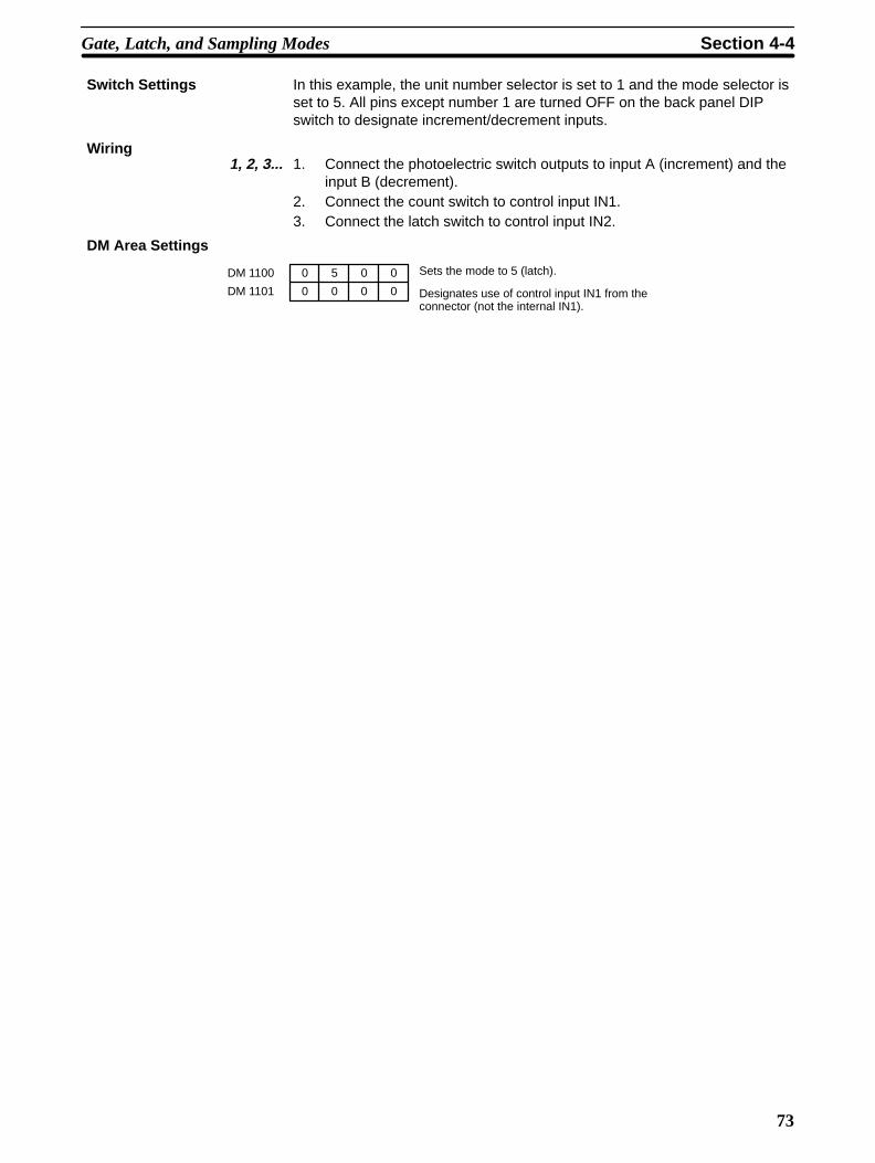
73
Switch Settings In this example, the unit number selector is set to 1 and the mode selector isset to 5. All pins except number 1 are turned OFF on the back panel DIPswitch to designate increment/decrement inputs.
Wiring1, 2, 3... 1. Connect the photoelectric switch outputs to input A (increment) and the
input B (decrement).2. Connect the count switch to control input IN1.3. Connect the latch switch to control input IN2.
DM Area Settings
DM 1100
DM 1101
0
0
5
0 0
0 0
0
Sets the mode to 5 (latch).
Designates use of control input IN1 from theconnector (not the internal IN1).
Gate, Latch, and Sampling Modes Section 4-4

74
Program
25315(ON for onecycle.)
MOV (21)
#1111
030
ANDW (34)
116
#00FF
001
MOVD (83)
116
#0012
001
001
001
001
ANDW (34)
#00FF
MOVD (83)
MOVD (83)
117
117
#0012
030
#0200
STC (40)
CLC (41)
ROL (27)
030
03000
03001
03002
03003
25313 NormallyOn
03015
03015
NormallyOn25313
Initializes strobe data.
Outputs 101 and 100 when strobe 0 = ”1”
Outputs 103 and 102 when strobe 1 = ”1”
Outputs 105 and 104 when strobe 2 = ”1”
Outputs 107 and 106 when strobe 3 = ”1”
Strobe signal output
Rotating the strobe data counterclockwise
Gate, Latch, and Sampling Modes Section 4-4
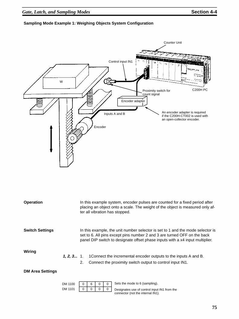
75
Sampling Mode Example 1: Weighing Objects System Configuration
Counter Unit
C200H PC
Control input IN1
Proximity switch forcount signal
Inputs A and B
Encoder
An encoder adapter is requiredif the C200H-CT002 is used withan open-collector encoder.
W
Encoder adapter
Operation In this example system, encoder pulses are counted for a fixed period afterplacing an object onto a scale. The weight of the object is measured only af-ter all vibration has stopped.
Switch Settings In this example, the unit number selector is set to 1 and the mode selector isset to 6. All pins except pins number 2 and 3 are turned OFF on the backpanel DIP switch to designate offset phase inputs with a x4 input multiplier.
Wiring1, 2, 3... 1. 1Connect the incremental encoder outputs to the inputs A and B.
2. Connect the proximity switch output to control input IN1.
DM Area Settings
DM 1100
DM 1101
0
0
6
0 0
0 0
0
Sets the mode to 6 (sampling).
Designates use of control input IN1 from theconnector (not the internal IN1).
Gate, Latch, and Sampling Modes Section 4-4

76
Program
25315 (ON for one cycle.)
MOV (21)
#3000
111
11001
DIFD (14) 03000
11400 Counting flag
03000
MOV (21)
116
DM 0000
MOV (21)
117
DM 0001
The current counter value is storedin DM 0000 and DM 0001 whenthe weighing is completed.
Detects the completion of weighing(OFF during counting).
SET TIME
Sets the sampling time to 3 s.
Sampling Mode Example 2: Measuring Speed System Configuration
Counter Unit
Input A
C200H PC
Encoder (single)Resolution: 200 pulses/revolution
Motor
An encoder adapter is required if the CT002 is used with anopen-collector encoder.
Encoderadapter
Operation This example system counts, for a specific interval, pulses from an incremen-tal encoder that is directly connected to a rotating shaft. The PC then con-verts the pulse count into a shaft speed (rpm). Here, the speed in rpm would
Gate, Latch, and Sampling Modes Section 4-4

77
be the number of pulses per second times 60 divided by the number ofpulses per shaft rotation (i.e., 200), or 0.3 times the pulse count per second.
Switch Settings In this examples, the unit number selector is set to 1 and the mode selectoris set to 6. All pins except pins 1 and 2 are turned OFF on the back panelDIP switch to designate pulse and direction inputs.
Wiring1, 2, 3... 1. Connect the incremental encoder output to the inputs A.
2. Do not connect any output to input B, and set the counter to increment.
DM Area Settings
DM 1100
DM 1101
0
0
6
0 0
0 0
1
Sets the mode to 6 (sampling).
Designates use of internal IN1 from thePC (not control input IN1).
Gate, Latch, and Sampling Modes Section 4-4

78
Program
25313 Normally ON.
MOV (21)
#1000
111
MOV (21)
MOV (21)
MOV (21)
MOV (21)
#0003
DM 0000
#0000
DM 0001
#0010
DM 0002
#0000
DM 0003
11400
TIM000
TIM001
TIM000
TIM001
11003
MULL (56)
DM 0000
116
DM 0004
DIVL (57)
DM 0004
DM 0004
DM 0002
1101
Sets the sampling time to 1,000 ms.
Inputs 0000 and 0003 to DM 0000 and DM 0001, respec-tively.
Inputs 0000 and 0010 to DM 0002 and DM 0003, respec-tively.
Turn the internal IN1 signal ON andOFF every 3 seconds.
Multiplies the counter value by 0.3when the counting flag turns OFFand stores the results in DM 0004and DM 0005.
Gate, Latch, and Sampling Modes Section 4-4

79
SECTION 5Error Processing
This section presents possible errors and solutions and describes how to handle errors from the PC. The AR area Errorand Restart Flags are described.
5-1 Error Indications . . . . . . . . . . . . . . . . . . . . . . . . . . . . . . . . . . . . . . . . . . . . . . . . . . . . . . . . . . 5-2 Troubleshooting from the PC . . . . . . . . . . . . . . . . . . . . . . . . . . . . . . . . . . . . . . . . . . . . . . . .
80
5-1 Error IndicationsWhen an error occurs, the ERROR indicator will light and the error flag will turnON. Error information is then output to IR word n+5 when READ ERROR is set.READ ERROR can be set as many times as necessary to access further errorinformation. (Information for up to 30 errors will be saved in the system.)
Error information in IR word n+5 consists of the error location, which indicatesthe last two digits of the DM address where the error originates, and the errorcode, which classifies the error (Refer to Appendix A Error Code List). The errorlocation is held in bits 07 through 00; the error, in bits 15 through 08.
If the counter value overflows, the ERROR indicator will light and the counteroverflow flag will turn ON. The error flag will not turn ON for counter overflows,and error information will not be output to IR word n+5.
If an error occurs, correct the cause of the error and clear all PC error flags. Errorinformation and the Counter Unit error flag will be cleared after all errors are readout with READ ERROR.
5-2 Troubleshooting from the PCErrors in the Counter Unit can be monitored from the PC. The Counter Unit ismonitored as a Special I/O Unit, and as such is treated the same as a PositionControl Unit or any other Special I/O Unit.
Error List for Special I/O UnitsError Possible cause and status Correction
Waiting for Special I/O Unitstartup.
•Special I/O Unit has a hardwaremalfunction.•PC will not begin operation.
•Replace the SpecialI/O Unit with a new Unit. (The malfunctioning Unitdisplays only $s when I/O table is read.)
Too many Special I/O Units. •Same unit number has been assigned to more than one SpecialI/O Unit.•PC will not begin operation.
•SR bit 25415 is ON.
•Set unit numbers so that each is used only once (Unit numbers can be accessedby reading I/O table.)
Error in Special I/O Unit. •Refreshing was not normallyexecuted between CPU and theSpecial I/O Unit.•Only the malfunctioning Unit willstop operation.•SR bit 25415 is ON.
•Obtain the malfunctioning Unit number byreading AR bits 0000 to 0009, remove the causeof the error, and then restart by turning OFF, ON,then back off the appropriate restart flag (AR bits0100 to 0109). If the Counter Unit does notrecover normal operation after restarting, replaceit with a new one.
Troubleshooting from the PC Section 5-2

81
AR Area Error and Restart Flags for Special I/O Units
Error Flags The following error flags will turn ON when the same unit number is assignedto more than one Special I/O Unit, or when the refreshing operation betweenthe PC and the Special I/O Unit is not normally executed.
Bit Unit number
AR 000 0
AR 001 1
AR 002 2
AR 003 3
AR 004 4
AR 005 5
AR 006 6
AR 007 7
AR 008 8
AR 009 9
Restart Flags The following restart flags are turned ON and OFF to restart Special I/OUnits. It is not necessary to turn OFF Counter Unit power when its restart flagis used.
Bit Unit number
AR 0100 0
AR 0101 1
AR 0102 2
AR 0103 3
AR 0104 4
AR 0105 5
AR 0106 6
AR 0107 7
AR 0108 8
AR 0109 9
Troubleshooting from the PC Section 5-2
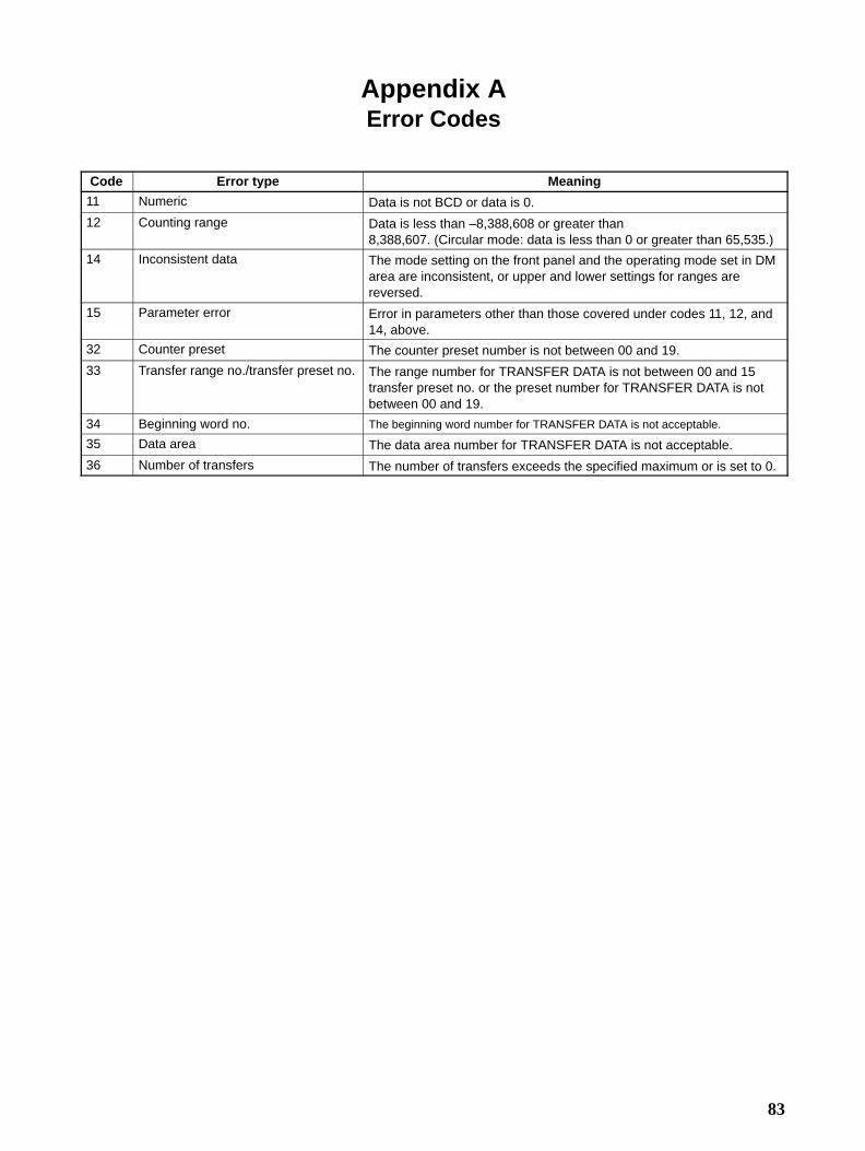
83
Appendix AError Codes
Code Error type Meaning
11 Numeric Data is not BCD or data is 0.
12 Counting range Data is less than –8,388,608 or greater than8,388,607. (Circular mode: data is less than 0 or greater than 65,535.)
14 Inconsistent data The mode setting on the front panel and the operating mode set in DMarea are inconsistent, or upper and lower settings for ranges arereversed.
15 Parameter error Error in parameters other than those covered under codes 11, 12, and14, above.
32 Counter preset The counter preset number is not between 00 and 19.
33 Transfer range no./transfer preset no. The range number for TRANSFER DATA is not between 00 and 15transfer preset no. or the preset number for TRANSFER DATA is notbetween 00 and 19.
34 Beginning word no. The beginning word number for TRANSFER DATA is not acceptable.
35 Data area The data area number for TRANSFER DATA is not acceptable.
36 Number of transfers The number of transfers exceeds the specified maximum or is set to 0.

85
Appendix BSpecifications
Item Specification
Number of axes One per Counter Unit
Operating modes Any of the following six:Linear mode Circular modePreset mode Gate modeLatch mode Sampling mode
Count input signals Input AInput B
Counting signal level CT001-V1: 5, 12, or 24 VDC (Selected when wiring).CT002: Same as RS-422 line driver (Am26LS31-compatible).
Input modes Offset phasesSeparate up and down inputsPulse and direction inputs
Counting speed CT001-V1: 50 kcps max.CT002: 75 kcps max.(Depends on encoder when using offset phase inputs. Refer to 3-2-1 Offsetphases).
Other Input multiplier (x2 or x4) available for offset phase inputs.
Input signals Input Z Control input IN1Control input IN2
External signal level CT001-V1: 5, 12, or 24 VDC (Selected when wiring).CT002: Same as RS-422 line driver (Am26LS31-compatible).
External outputs 8 total
Output level External output power supply: 5 to 24 VDCSwitching capacity: 16 to 80 mA
Internal consumption 300 mA max. at 5 VDC (supplied from rack).
Weight 400 g max. (excluding connectors).
Maximum Required Response Speed (Pulse Input to Output)No. of ranges Linear mode Circular mode
1 0.74 ms 0.66 ms
8 1.17 ms 1.02 ms
16 1.40 ms 1.10 ms
Note Add the I/O refresh time (approximately 3 ms) to the values in the above table tocompute the response speed when the I/O refresh timing differs from the outputtiming.

Specifications Appendix B
86
I/O Specifications
Output Specifications (Outputs 0 through 7)Item Specification
Switching capacity 6 mA at 4.5 VDC to 80 mA at 26.4 VDC (Refer to table below.) Maximum: 320 mA/common
Leak current 0.1 mA max.
Residual voltage 0.4 V max.
ON/OFF response time High-speed counting process time 0.3 ms
External power supply 5 to 24 VDC + 10% (50 mA max. at 26.4 VDC)
Switching capacity Maximum Switching Capacity: Power Supply Characteristic. The maximum switchingcapacity is determined by the power supply as shown in the following diagram:
0 4.5 10 20.4 26.4
16
50
80
Switching capacity
External power supply

Appendix BSpecifications
87
C200H-CT001-V1 Input SpecificationsItem Inputs A, B, and Z Control inputs IN1 and IN2
Input voltage 5 VDC10% 12 VDC10% 24 VDC10% 5 VDC10% 12 or 24VDC10%
Input current 12 mA typical (7.5 to 18 mA) 4 to 7 mA 4 to 13 mA
ON voltage (min.) 4.5 VDC 10.2 VDC 21.6 VDC 4.5 VDC 10.2 VDC
OFF voltage (max.) 2.0 VDC 3.0 VDC 4.0 VDC 2.0 VDC 3.0 VDC
ON/OFF responsetime
--- 1 ms max.
Minimum responsetime
*Inputs A and B Waveform of inputs A and B Rise/fall time: 3µs max. 50 kHz,50% pulse
10 µs min. 10 µs min.
20 µs min.
3 µs max. 3 µs max.
Relation between inputs A and B for offset phase Inputs
ON50%OFF
20 µs min.
ON50% input AOFF
ONPhase BOFF
T1T2
T3T4
T1, T2, T3, T4: 4.5 µsec min.
There must be at least a 4.5-µs interval between thechange point of input A and that of input B.*Input Z A pulse width of at least 0.1 ms is required.
ON50%OFF
0.1 ms min. 0.1 ms min.
Note: These signals must re-main ON for at least thelength of the PC’s cycletime to be accuratelyread from the PC.
ON
OFF
0.1 ms min.
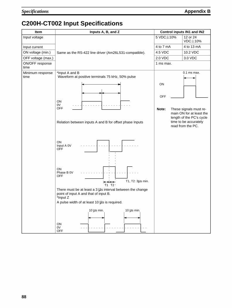
Specifications Appendix B
88
C200H-CT002 Input SpecificationsItem Inputs A, B, and Z Control inputs IN1 and IN2
Input voltage 5 VDC10% 12 or 24VDC10%
Input current 4 to 7 mA 4 to 13 mA
ON voltage (min.) Same as the RS-422 line driver (Am26LS31-compatible). 4.5 VDC 10.2 VDC
OFF voltage (max.) 2.0 VDC 3.0 VDC
ON/OFF responsetime
1 ms max.
Minimum responsetime
*Input A and B Waveform at positive terminals 75 kHz, 50% pulse
ON0VOFF
Relation between inputs A and B for offset phase Inputs
ONInput A 0VOFF
ONPhase B 0VOFF
T1 T2T1, T2: 3µs min.
There must be at least a 3 µs interval between the change point of input A and that of input B.*Input ZA pulse width of at least 10 µs is required.
10 µs min. 10 µs min.
ON0VOFF
ON
OFF
0.1 ms max.
Note: These signals must re-main ON for at least thelength of the PC’s cycletime to be accuratelyread from the PC.

89
Appendix CIR Area Allocations
(n = 100 + 10 x unit no.)
Linear and Circular Operating ModesWord Bit
15 14 13 12 11 10 09 08 07 06 05 04 03 02 01 00
#7 #6 #5 #4 #3 #2 #1 #0
Out
put
n Output force bits
EN
AB
LE F
OR
CE
D O
UT
PU
T
RE
SE
T C
OU
NT
ER
RE
AD
ER
RO
R
CH
AN
GE
PR
ES
ET
---
EN
AB
LE F
OR
CE
D O
UT
PU
T
TR
AN
SF
ER
DA
TA
STA
RT
n+1 Range enable bits
n+2 TRANSFER DATA beginning channel number
n+3 Number of transfers TRANSFER DATA data area
Inpu
t
n+4 ---
Res
et C
ompl
eted
Cou
nt o
verf
low
flag
Err
or fl
ag
Tran
sfer
com
plet
ed fl
ag
IN2
flag
IN1
flag
Z fl
ag
Cou
ntin
g fla
g
n+5 Error code Error location
n+6 Current counter value (rightmost 4 digits)
n+7 Current counter value (sign and leftmost 3 digits)
n+8 Range flags
n+9 Output flags
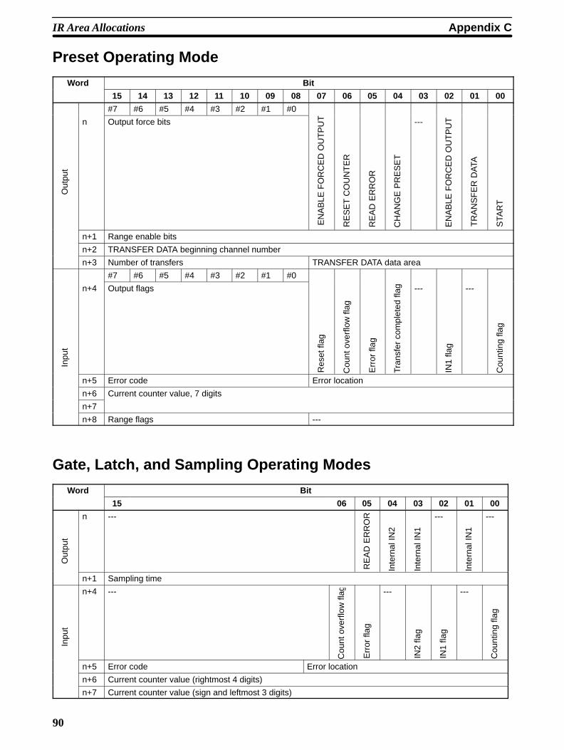
IR Area Allocations Appendix C
90
Preset Operating Mode
Word Bit
15 14 13 12 11 10 09 08 07 06 05 04 03 02 01 00
#7 #6 #5 #4 #3 #2 #1 #0
Out
put
n Output force bits
EN
AB
LE F
OR
CE
D O
UT
PU
T
RE
SE
T C
OU
NT
ER
RE
AD
ER
RO
R
CH
AN
GE
PR
ES
ET
---
EN
AB
LE F
OR
CE
D O
UT
PU
T
TR
AN
SF
ER
DA
TA
STA
RT
n+1 Range enable bits
n+2 TRANSFER DATA beginning channel number
n+3 Number of transfers TRANSFER DATA data area
#7 #6 #5 #4 #3 #2 #1 #0
Inpu
t
n+4 Output flags
Res
et fl
ag
Cou
nt o
verf
low
flag
Err
or fl
ag
Tran
sfer
com
plet
ed fl
ag ---
IN1
flag
---
Cou
ntin
g fla
g
n+5 Error code Error location
n+6 Current counter value, 7 digits
n+7
n+8 Range flags ---
Gate, Latch, and Sampling Operating Modes
Word Bit
15 06 05 04 03 02 01 00
Out
put
n ---
RE
AD
ER
RO
R
Inte
rnal
IN2
Inte
rnal
IN1
---
Inte
rnal
IN1
---
n+1 Sampling time
Inpu
t
n+4 ---
Cou
nt o
verf
low
flag
Err
or fl
ag
---
IN2
flag
IN1
flag
---
Cou
ntin
g fla
g
n+5 Error code Error location
n+6 Current counter value (rightmost 4 digits)
n+7 Current counter value (sign and leftmost 3 digits)
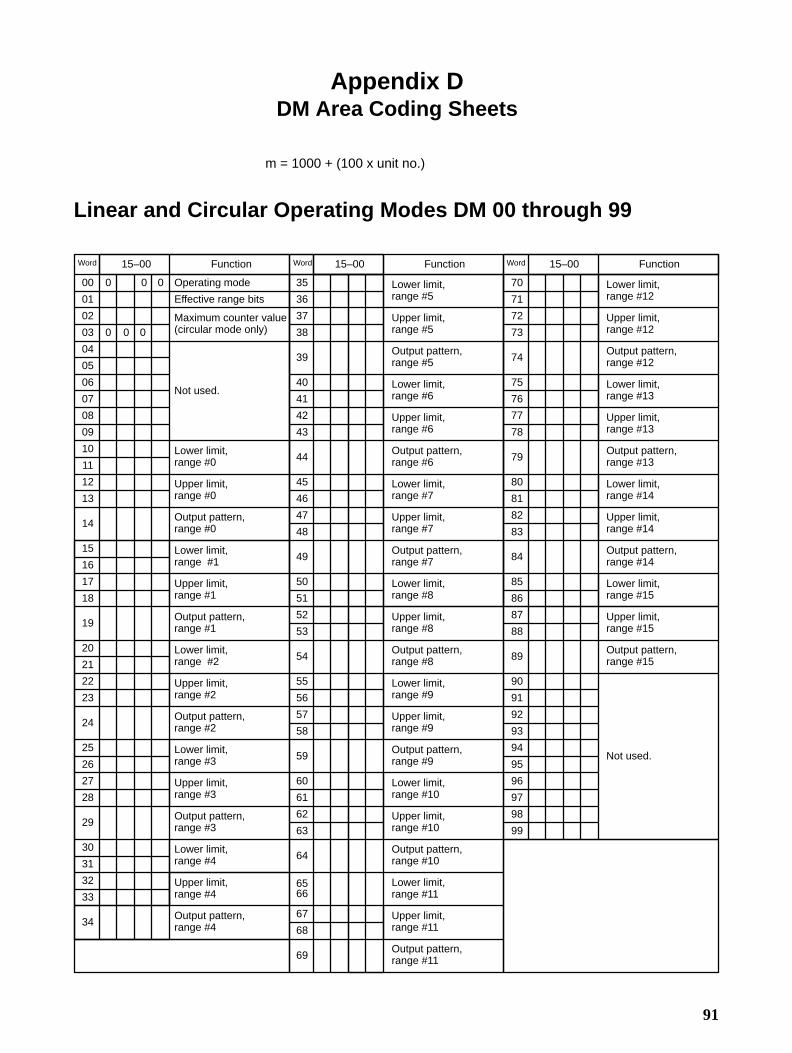
91
Appendix DDM Area Coding Sheets
m = 1000 + (100 x unit no.)
Linear and Circular Operating Modes DM 00 through 99
Word 15–00 Function
00
01
02
03
04
05
06
07
08
09
10
11
12
13
14
15
16
17
18
19
20
21
22
23
24
25
26
27
28
29
30
31
32
33
34
35
36
37
38
39
40
41
42
43
44
45
46
47
48
49
50
51
52
53
54
55
56
57
58
59
60
61
62
63
64
6566
67
68
69
70
71
72
73
74
75
76
77
78
79
80
81
82
83
84
85
86
87
88
89
90
91
92
93
94
95
96
97
98
99
Operating mode
Effective range bits
Maximum counter value(circular mode only)
Not used.
Lower limit, range #0
Upper limit, range #0
Output pattern,range #0
Lower limit, range #1
Upper limit, range #1
Output pattern,range #1
Lower limit,range #2
Upper limit, range #2
Output pattern,range #2
Lower limit, range #3
Upper limit, range #3
Output pattern,range #3
Lower limit, range #4
Upper limit, range #4
Output pattern,range #4
Lower limit, range #5
Upper limit, range #5
Output pattern,range #5
Lower limit, range #6
Upper limit, range #6
Output pattern,range #6
Lower limit, range #7
Upper limit, range #7
Output pattern,range #7
Lower limit, range #8
Upper limit, range #8
Output pattern,range #8
Lower limit, range #9
Upper limit, range #9
Output pattern,range #9
Lower limit, range #10
Upper limit, range #10
Output pattern,range #10
Lower limit, range #11
Upper limit, range #11
Output pattern,range #11
Lower limit, range #12
Upper limit, range #12
Output pattern,range #12
Lower limit, range #13
Upper limit, range #13
Output pattern,range #13
Lower limit, range #14
Upper limit, range #14
Output pattern,range #14
Lower limit, range #15
Upper limit, range #15
Output pattern,range #15
Not used.
0 0 0
0 0 0
15–00 Function 15–00 FunctionWord Word

DM Area Coding Sheets Appendix D
92
Preset Operating Mode
Word 15–00 Function 15–00 Function 15–00 Function
00
01
02
03
04
05
06
07
08
09
10
11
12
13
14
15
16
17
18
19
20
21
22
23
24
25
26
27
28
29
30
31
32
33
35
36
37
38
39
40
41
42
43
44
45
46
47
48
49
50
51
52
53
54
55
56
57
58
59
60
61
62
63
64
65
66
67
70
71
72
73
74
75
76
77
78
79
80
81
82
83
84
85
86
87
88
89
90
91
92
93
94
95
96
97
98
99
0 3 0 0 Operating mode
OFF counter valuefor output #0
ON counter value for output #1
OFF counter valuefor output #1
OFF counter valuefor output #2
ON counter value for output #2
ON time for outputs #4through #7
0
0
0
0
0
Not used.
Preset #0
Preset #1
Preset #2
Preset #3
Preset #4
Preset #5
Preset #6
Preset #7
Preset #8
Preset #9
Preset #10
Preset #11
Preset #12
Preset #13
Preset #14
Preset #15
Preset #16
Preset #17
Preset #18
Preset #19
Not used.
34
69
68
Word Word
Gate, Latch and Sampling Operating Modes
Word 15–00
00
01
0
0
0
0
0
Function
Operating mode (4: gate; 5: latch; or 6: sampling)
Control origin and gate mode type

93
Index
A-C
Am26LS31–compatible,
applications, precautions,
AR area, error and restart flags,
circular modedescription, DM area allocation, IR area allocation, IR area settings/commands, maximum counter value, operation, timing relationships, use with Offset Phase input, use with Pulse and Direction inputs, use with Up and Down Pulse input,
commandCHANGE RANGES, in linear/circular mode, ENABLE FORCED OUTPUT
in linear/circular mode, in preset mode,
ENABLE OUTPUTin linear/circular mode, in preset mode,
PRESET COUNTER, in preset mode, READ ERROR
in gate, latch and sampling mode, in linear/circular mode, in preset mode,
RESET COUNTER, in linear/circular mode, SET TIME, in gate, latch and sampling mode, START
in linear/circular mode, in preset mode,
TRANSFER DATAin linear/circular mode, in preset mode,
connections,
connectorassembly, differentiating input and output cables, Fujitsu FCN–361J040, input pin settings, pin arrangement, pin numbers, solder type, type, ,
counting speed, Offset Phase input,
cycle time, transferring data,
D
data allocation, gate, latch and sampling modes,
data format,
data transfer, See also Unit, Counter – transferring dataarea, delay precaution, in Remote I/O Systems, relation to PC scan time, source,
DIP switch setting. See Unit, Counter – switch setting
DM areaallocation, allocation in preset mode, data allocation in gate, latch and sampling mode, settings, , settings in preset mode, word allocation, ,
E
error, flag/indicator operation,
example12 VDC Voltage–Output Synch–Load Encoder, 24 VDC Open–collector Encoder, 5 VDC Voltage–Output Source–Load Encoder, C200H–CT001–V1 input circuit wiring, C200H–CT002, circular mode, functioning as mechanical cam switches, control input wiring, determining acceptable product length, external output wiring, gate mode, measuring product length, latch mode, monitoring quantity at a processing station, Line–Driver Encoder, linear mode, controlling conveyor processing, Open–collector Encoder and Encoder Adapter, preset mode, measuring and cutting rod, sampling mode
measuring speed, weighing objects,
to prevent chattering, transferring range parameters, transferring the counter value,
external outputs, modes,
F
flagcount overflow
in gate, latch and sampling mode, in linear/circular mode, in preset mode,
countingin gate, latch and sampling mode, in linear/circular mode, in preset mode,
Index
94
errorin gate, latch and sampling mode, in linear/circular mode, in preset mode,
error in operation, IN1
in gate, latch and sampling mode, in linear/circular mode, in preset mode,
IN2in gate, latch and sampling mode, in linear/circular mode,
outputin linear/circular mode, in preset mode,
range, in linear/circular mode, reset
in linear/circular mode, in preset mode,
transfer complete, in preset mode, transfer completed, in linear/circular mode, Z, in linear/circular mode,
Fujitsu FCN–361J040 connector,
fuse,
G-I
gate modedescription, operation, timing relationships,
I/O refresh cycle, transferring data,
incremental encoder,
input circuit, C200H–CT001–V1, C200H–CT002,
installation, precautions,
interference, ,
IR areaallocation, allocation in preset mode, commands, in gate, latch and sampling mode, settings, settings in preset mode, word allocation, ,
L-O
latch modedescription, operation, timing relationships,
LED indicators,
linear modedescription,
DM area allocation, IR area allocation, IR area settings/commands, operation, timing relationships, use with Offset Phase input, use with Pulse and Direction inputs, use with Up and Down Pulse input,
multi–core cable,
noise,
noise resistance,
Offset Phase input. See Unit, Counter – Offset Phase input
operating environment, precautions,
operating mode, switch settings,
operating mode selector,
operating modescircular, gate, input types, latch, linear, preset, sampling,
output circuit, C200H–CT001–V1, C200H–CT002,
P
PC, max number of Special I/O Units,
power supplyoutput current, preventing interference, terminals, voltage,
precautiondata transfer delay, switch setting, wiring,
precautions, applications, general, operating environment, safety,
preset modedescription, operation, timing relationships,
R-S
RS–422,
safety precautions. See precautions
sampling modedescription, operation, timing relationships,

Index
95
specifications, Encoder,
switch settingSee also Unit, Counter – switch settingprecaution, using the multiplier,
switch settings,
T
timing chartlinear/circular mode, preset mode,
timing chartsgate mode, latch mode, sampling mode,
transferring data. See data transfer
U
Unit, Counterassigning Unit numbers, circular mode, connector pin arrangement, dimensions, dimensions mounted, error code listing, error flags, error listing, example configuration, front view, indicators, input and output circuits,
input circuit examples, input selection, linear mode, mounting location, Offset Phase input, operating modes, , operation, pin settings, Pulse Direction input, reset conditions, reset point, resetting, , restart flags, specifications, switch setting, switch settings, , the count range, transferring data, , Up and Down Pulse input, wiring, word allocation,
Unit, Special I/Oassigning Unit numbers, error flags, error listing, max no. per PC, restart flags, word allocation,
W
wiringconnector pin arrangement, precaution, the connector,

97
Revision History
A manual revision code appears as a suffix to the catalog number on the front cover of the manual.
Cat. No. W141-E1-4
Revision code
The following table outlines the changes made to the manual during each revision. Page numbers refer to theprevious version.
Revision code Date Revised content
1 September 1989 Original production
2 December 1990 Converted to current format.
2A October 1994 Complete layout change. Scan time changed to cycle time throughout the manual. Correc-tions made and product functionality added as follows:
Page 9: Setting of pin 4 added for preset counter operating mode.
Pages 10, 11: Row B information corrected for pin number 8.
Page 16, 17: Power supply voltage changed to 12 VDC.
Page 35: Note added on operation of transfer complete flag.
Page 45: Paragraph added to START explanation. Explanation of ENABLE OUTPUTcorrected.
Page 46: “I/O” area changed to “IR” area.
Page 48: Second instruction line and function code of DIFD corrected.
Page 50: Second instruction line and function code of DIFD corrected.
Page 58: Explanation changed to say that either START or external control input IN2 canbe used as start signal for counter.
Page 62: Output numbers corrected for bits 10 through 15.
Page 64: Explanation of ENABLE OUTPUT corrected.
Page 66: Information added on operation of counting flag.
Page 67: Information corrected concerning CT001-V1 support of bit 07.
Page 73: Notes added after table.
Page 85: Switch setting corrected.
Page 99: Specifications for the external signal level and output level changed. Note add-ed concerning response speed.
Page 100: Leak current corrected to 0.1 mA.
Pages 101, 102: Note added on signal length of IN1 and IN2.
2B July 1995 The following corrections/additions were made.
Page 12: Diagram of connector pin numbers added.
Page 40: The following mistake was deleted: When counting is started, the currentcounter value is reset to 0 and external outputs #0 through #7 are turned OFF.
Pages 41, 58: Note added on useable DM and IR words.
Page 45: Precaution added on Z flag operation.
2C August 1996 Page 14: The pin number B15 for the fourth circuit corrected to B12.
Page 37: “Lower limit” corrected to “upper limit for words m+12 and m+13.
Page 38: Output numbers for bits 01 to 15 of input word n+9 corrected to 1 to 15 respec-tively.
3 April 2000 A precautions section was added to the beginning of the manual and the following changeswere made.
Pages 36 and 69: Notes added.
4 September 2000 Page xiii: Minor change made to wording of information on mounting.
Pages 14 and 16: Changes made to graphics in several places.

Cat. No. W141-E1-4 Note: Specifications subject to change without notice. Printed in Japan
Authorized Distributor: