Embed Size (px)
Citation preview
54
ModelApplicable valve
Applicable flat ribbon cable connector Internal wiring Rated voltage
Manifold typeP (SUP)/R (EXH)Valve stationsA, B port location
Port size
Manifold base weight W (g)n: Stations
P, EA, EB port
A, B port
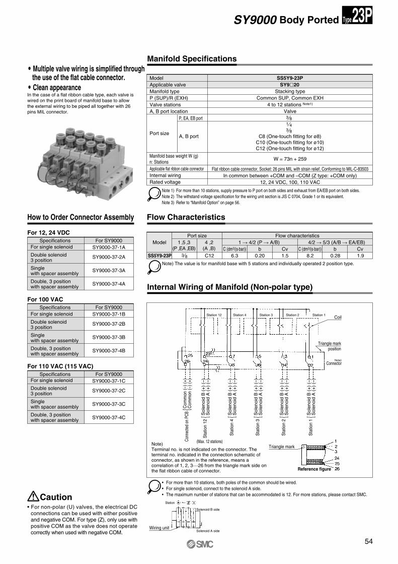
SS5Y9-23PSY9�20
Stacking typeCommon SUP, Common EXH
4 to 12 stations Note1)
Valve3 81 43 8
C8 (One-touch fitting for ø8)C10 (One-touch fitting for ø10)C12 (One-touch fitting for ø12)
W = 73n + 259
Flat ribbon cable connector, Socket: 26 pins MIL with strain relief, Conforming to MIL-C-83503In common between +COM and –COM (Z type: +COM only)
12, 24 VDC, 100, 110 VAC
Note 1) For more than 10 stations, supply pressure to P port on both sides and exhaust from EA/EB port on both sides.Note 2) The withstand voltage specification for the wiring unit section is JIS C 0704, Grade 1 or its equivalent.Note 3) Refer to “Manifold Option” on page 56.
• For more than 10 stations, both poles of the common should be wired. • For single solenoid, connect to the solenoid A side.• The maximum number of stations that can be accommodated is 12. For more stations, please contact SMC.
• For non-polar (U) valves, the electrical DC connections can be used with either positive and negative COM. For type (Z), only use with positive COM as the valve does not operate correctly when used with negative COM.
SY9000 Body Ported
Manifold Specifications
Internal Wiring of Manifold (Non-polar type)
Caution
In the case of a flat ribbon cable type, each valve is wired on the print board of manifold base to allow the external wiring to be piped all together with 26 pins MIL connector.
How to Order Connector Assembly
Specifications For SY9000SY9000-37-1A
SY9000-37-2A
SY9000-37-3A
SY9000-37-4A
For 12, 24 VDC
For 100 VAC
For 110 VAC (115 VAC)
Specifications For SY9000SY9000-37-1B
SY9000-37-2B
SY9000-37-3B
SY9000-37-4B
Specifications For SY9000SY9000-37-1C
SY9000-37-2C
SY9000-37-3C
SY9000-37-4C
Flow Characteristics
3 8 C12 6.3 0.20 1.5 8.2 0.28 1.9
Model 1 ,5 ,3 (P ,EA ,EB)
4 ,2 (A ,B)
1 � 4/2 (P � A/B) 4/2 � 5/3 (A/B � EA/EB) Port size Flow characteristics
C (dm3/(s·bar)) b Cv C (dm3/(s·bar)) b CvSS5Y9-23P
Note) The value is for manifold base with 5 stations and individually operated 2 position type.
23PType
� Multiple valve wiring is simplified through the use of the flat cable connector.
� Clean appearance
Note)Terminal no. is not indicated on the connector. The terminal no. indicated in the connection schematic of connector, as shown in the reference, means a correlation of 1, 2, 3····26 from the triangle mark side on the flat ribbon cable of connector.
For single solenoid
Double solenoid3 position
Single with spacer assembly
Double, 3 position with spacer assembly
For single solenoid
Double solenoid3 position
Single with spacer assembly
Double, 3 position with spacer assembly
For single solenoid
Double solenoid3 position
Single with spacer assembly
Double, 3 position with spacer assembly
Station 12 Station 4 Station 3 Station 2 Station 1 Coil
Triangle markposition
Note)Connector
Sol
enoi
d B
(+
) (–
)S
olen
oid
A (
+)
(–)
Sta
tion
1 {S
olen
oid
B (
+)
(–)
Sol
enoi
d A
(+
) (–
)S
tatio
n 2
{Sol
enoi
d B
(+
) (–
)S
olen
oid
A (
+)
(–)
Sta
tion
3 {S
olen
oid
B (
+)
(–)
Sol
enoi
d A
(+
) (–
)S
tatio
n 4
{Sol
enoi
d B
(+
) (–
)S
olen
oid
A (
+)
(–)
Sta
tion
12 {
Com
mon
(–) (
+)C
omm
on (–
) (+)
Conn
ecte
d on
PCB
{
(Max. 12 stations)Triangle mark
Reference figure
Wiring unit
Station
Solenoid A side
Solenoid B side
SY.qxd 03.11.11 8:37 AM Page 54
55
Body Ported
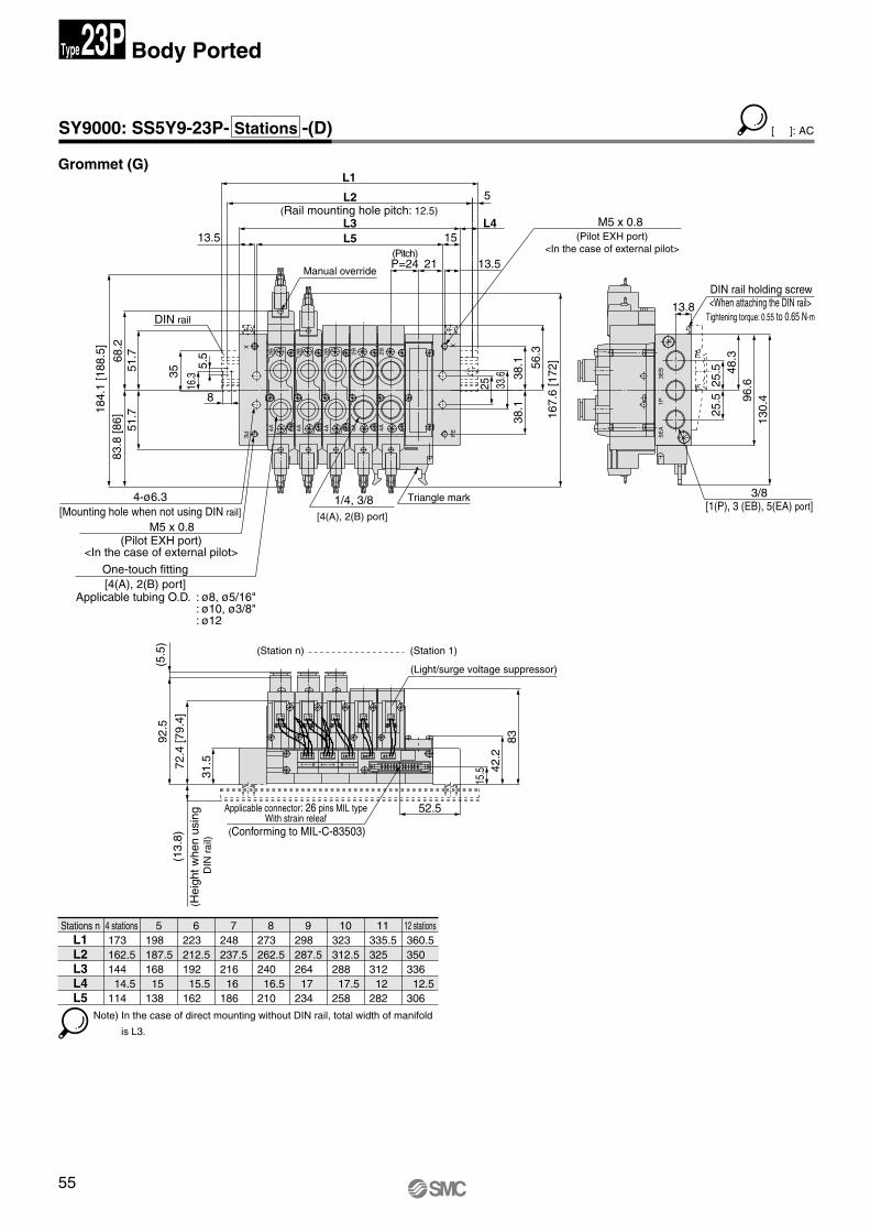
SY9000: SS5Y9-23P- Stations -(D)
Stations n173162.514414.5
114
198187.516815
138
223212.519215.5
162
248237.521616
186
273262.524016.5
210
298287.526417
234
323312.5288
17.5258
335.5325312
12282
360.5350336
12.5306
L1L2L3L4L5
Grommet (G)
-+-+-+-+ -+
-+
-+
2B4A
2B4A
2B4A
2B4AP
EX
2B4A
PE
X
8
[Mounting hole when not using DIN rail]
(Pilot EXH port)<In the case of external pilot>
DIN rail
Applicable tubing O.D. : ø8, ø5/16": ø10, ø3/8": ø12
[4(A), 2(B) port]One-touch fitting
(Pilot EXH port)<In the case of external pilot>
Manual override
(Pitch)
(Rail mounting hole pitch: 12.5)
15L513.5
P=24 21 13.5
L3
L2
L1
51.7
51.7
68.2
184.
1 [1
88.5
]
16.3
5.5
35
83.8
[86]
4-ø6.3
M5 x 0.8
33.6
25
38.1
38.1 56
.316
7.6
[172
]
1/4, 3/8
M5 x 0.8
5EA
3EB
1P
<When attaching the DIN rail>Tightening torque: 0.55 to 0.65 N·m
DIN rail holding screw
[1(P), 3 (EB), 5(EA) port]
130.
4
25.5
25.5 96
.6
13.8
48.3
3/8
L4
5
- +- +-+- +- +
(Conforming to MIL-C-83503)
Applicable connector: 26 pins MIL type With strain releaf
(Hei
ght w
hen
usin
g D
IN r
ail)
(Station n)
(5.5
)
31.5
15.5 42
.2
52.5
72.4
[79.
4](1
3.8)
92.5
83
(Light/surge voltage suppressor)
(Station 1)
Triangle mark
[4(A), 2(B) port]
23PType
[ ]: AC
Note) In the case of direct mounting without DIN rail, total width of manifold
is L3.
4 stations 5 6 7 8 9 10 11 12 stations
SY.qxd 03.11.11 8:37 AM Page 55
56
Manifold Option
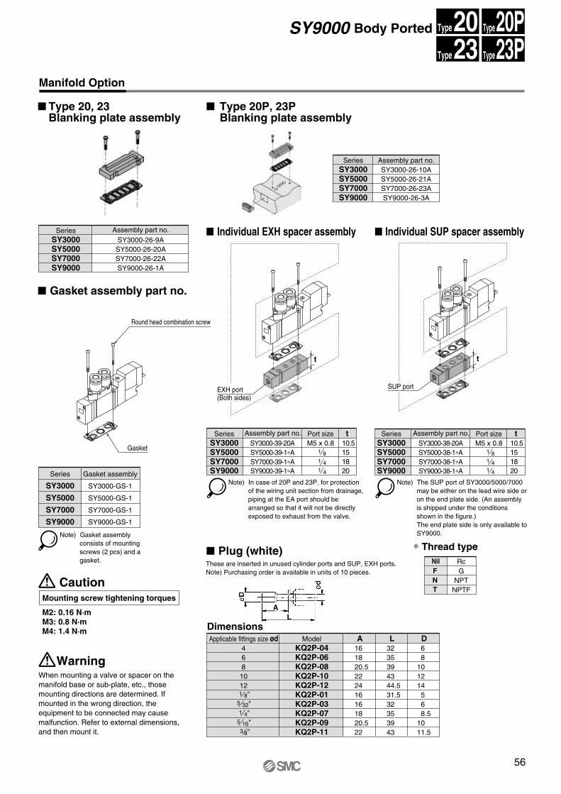
� Type 20, 23 Blanking plate assembly
� Gasket assembly part no.
� Type 20P, 23P Blanking plate assembly
� Individual EXH spacer assembly
� Plug (white) ∗ Thread type
� Individual SUP spacer assemblySeries Assembly part no.SY3000 SY3000-26-9ASY5000 SY5000-26-20ASY7000 SY7000-26-22ASY9000 SY9000-26-1A
Series Assembly part no. Port sizeM5 x 0.8
t10.5151820
SY3000 SY3000-39-20ASY5000 SY5000-39-1∗ASY7000 SY7000-39-1∗A
1 81 4
SY9000 SY9000-39-1∗A 1 4
Series Assembly part no. Port sizeM5 x 0.8SY3000 SY3000-38-20A
SY5000 SY5000-38-1∗ASY7000 SY7000-38-1∗A
1 81 4
SY9000 SY9000-38-1∗A 1 4
Note) In case of 20P and 23P, for protection of the wiring unit section from drainage, piping at the EA port should be arranged so that it will not be directly exposed to exhaust from the valve.
Note) Gasket assembly consists of mounting screws (2 pcs) and a gasket.
Note) The SUP port of SY3000/5000/7000 may be either on the lead wire side or on the end plate side. (An assembly is shipped under the conditions shown in the figure.)The end plate side is only available to SY9000.
Series
SY3000
SY5000
SY7000
Gasket assembly
SY3000-GS-1
SY5000-GS-1
SY7000-GS-1
SY9000 SY9000-GS-1
Series Assembly part no.SY3000-26-10ASY5000-26-21ASY7000-26-23A
SY3000SY5000SY7000
SY9000-26-3ASY9000
Applicable fittings size ød4
Model A L DKQ2P-04 16 32 6
6 KQ2P-06 18 35 88 KQ2P-08 20.5 39 1010 KQ2P-10 22 43 1212 KQ2P-12 24 44.5 14
KQ2P-01 16 31.5 5KQ2P-03 16 32 6KQ2P-07 18 35 8.5KQ2P-09 20.5 39 10KQ2P-11 22 43 11.5
Dimensions
SY9000 Body Ported
When mounting a valve or spacer on the manifold base or sub-plate, etc., those mounting directions are determined. If mounted in the wrong direction, the equipment to be connected may cause malfunction. Refer to external dimensions, and then mount it.
Warning
CautionMounting screw tightening torques
M2: 0.16 N·mM3: 0.8 N·mM4: 1.4 N·m
Rc
NPT
Nil
NNPTFT
GF
5 32"1 4"
5 16"3 8"
1 8"
t10.5151820
t t
20Type 20PType
23Type 23PType
These are inserted in unused cylinder ports and SUP, EXH ports.Note) Purchasing order is available in units of 10 pieces.
SUP portEXH port(Both sides)
Gasket
Round head combination screw
SY.qxd 03.11.11 8:37 AM Page 56
57
Body Ported
Manifold Option
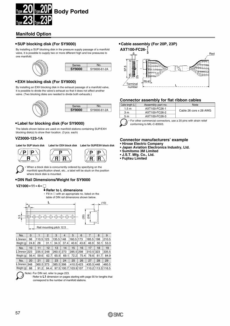
� SUP blocking disk (For SY9000) � Cable assembly (For 20P, 23P)
Series No. SY9000 SY9000-61-2A
Series No. SY9000 SY9000-61-2A
By installing a SUP blocking disk in the pressure supply passage of a manifold valve, it is possible to supply two or more different high and low pressures to one manifold.
� EXH blocking disk (For SY9000)By installing an EXH blocking disk in the exhaust passage of a manifold valve, it is possible to divide the valve’s exhaust so that it does not affect another valve. (Two blocking disks are needed to divide both exhausts.)
� Label for blocking disk (For SY9000)
� DIN Rail Dimensions/Weight for SY9000
VZ3000-123-1A
The labels shown below are used on manifold stations containing SUP/EXH blocking disk(s) to show their location. (3 pcs. each)
∗ When a block disk is concurrently ordered by specifying on the manifold specification sheet, etc., a label will be stuck on the position where block disk is mounted.
No.L Dimension Weight (g)
L Dimension Weight (g)
L Dimension Weight (g)
9824.8
110.528
12331.1
135.534.3
14837.4
160.540.6
17343.8
185.546.9
19850.1
210.553.3
22356.4
235.559.6
24862.7
260.565.9
27369.1
285.572.2
29875.4
310.578.6
32381.7
335.584.9
No.
No.
411VZ1000Refer to L dimensions
Cable length (L)1.5 m3 m5 m
AXT100-FC26-1Assembly part no.
AXT100-FC26-2AXT100-FC26-3
Note
Cable 26 core x 28 AWG
∗ For other commercial connectors, use a 20 pins with strain relief conforming to MIL-C-83503.
Note) ·For DIN rail, refer to page 223.·Refer to L1 dimension on pages starting with page 55 for lengths that correspond to the number of manifold stations.
Label for SUP block disk Label for EXH block disk Label for SUP/EXH block disk
34888
360.591.2
37394.4
385.597.5
398100.7
410.5103.9
423107
435.5110.2
448113.3
460.5116.5
Connector assembly for flat ribbon cables
Connector manufacturers’ example• Hirose Electric Company• Japan Aviation Electronics Industry, Ltd.• Sumitomo 3M Limited• J.S.T. Mfg. Co., Ltd.• Fujitsu Limited
AXT100-FC26-1|3
(10)
(24
)
(35
)
L8
5.5
Rail mounting pitch 12.5
20Type 20PType
23Type 23PType
∗ Fill in � with an appropriate no. listed on the table of DIN rail dimensions shown below.
Red
Terminalnumber
0 1 2 3 4 5 6 7 8 9
10 11 12 13 14 15 16 17 18 19
20 21 22 23 24 25 26 27 28 29
SY.qxd 03.11.11 8:37 AM Page 57
58
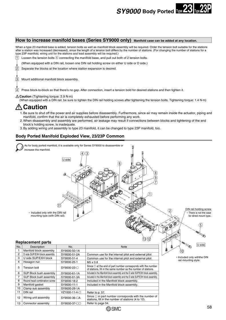
How to increase manifold bases (Series SY9000 only) Manifold case can be added at any location.
Body Ported Manifold Exploded View, 23/23P Common
When a type 23 manifold base is added, tension bolts as well as manifold block assembly will be required. Order the tension bolt suitable for the stations after a station was increased (decreased), since the length of a tension bolt differs by the number of stations. (For changing the number of stations for a type 23P manifold, wiring unit for the stations and lead assembly will be required.)
1
2
3
4
Caution (Tightening torque: 2.9 N·m)(When equipped with a DIN rail, be sure to tighten the DIN rail holding screws after tightening the tension bolts. Tightening torque: 1.4 N·m)
Caution1. Be sure to shut off the power and air supplies before disassembly. Furthermore, since air may remain inside the actuator, piping and
manifold, confirm that the air is completely exhausted before performing any work.2. When disassembly and assembly are performed, air leakage may result if connections between blocks and tightening of the end
block’s holding screw, is inadequate. 3. By adding wiring unit assembly to type 23 manifold, it can be changed to type 23P manifold, too.
SY9000 Body Ported
No.1234
5
67891011
12
13
DescriptionSY9000-50-1ASY9000-51-2ASY9000-51-4SY9000-25-1
SY9000-61-1ASY9000-61-3ASY9000-18-2SY9000-11-1SY9000-29-1AVZ1000-11-4-�
SY9000-36-�A
SY9000-37-��
SY9000-23-�
No. Note
Tension bolt
Replacement parts
U side
+ –
+ –
– +
!1DIN rail holding screw
23Type 23PType
Loosen the tension bolts t connecting the manifold base, and pull out both of 2 tension bolts.
(When equipped with a DIN rail, loosen one DIN rail holding screw on either U side or D side.)
Separate the blocks at the location where station expansion is desired.
Mount additional manifold block assembly.
Press block-to-block so that there's no gap. After connection, insert a tension bold for desired stations and then tighten it.
As for body ported manifold, it is available only for Series SY9000 to disassemble or
increase the manifold.
∗ Included only with the DIN rail mounting type (with DIN rail).
Common use for the internal pilot and external pilot Common use for the internal pilot and external pilot M5 x 0.8 Since � at the end of part number corresponds with the number of stations, fill in the same number as the number of stations.Included in the Manifold block assembly and the D side SUP/EXH block assembly. Included in the Manifold block assembly and the D side SUP/EXH block assembly. Included in the Manifold block assembly.Included in the Manifold block assembly.
Refer to p. 57.Since � in part number corresponds with the number of stations, fill in the number of stations (4 to 12).Refer to page 54.
∗ Included only withthe DIN rail mounting style.
U side
∗ There is not the case for direct mount type.
Manifold block assemblyD side SUP/EXH block assemblyU side SUP/EXH blockHexagon nut
SUP Block bush assemblySUP Block bush assemblyRound head combination screwManifold gasketClamp sub assemblyDIN rail
Wiring unit assembly
Connector assembly
re
y
iou
q
w
t
!0
!2!3
SY.qxd 03.11.11 8:37 AM Page 58
59
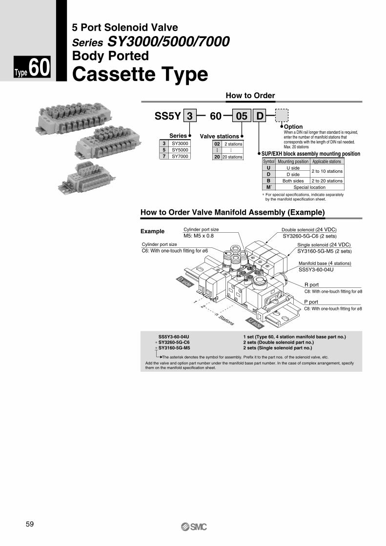
Cassette Type
Series SY3000/5000/7000 Body Ported
5 Port Solenoid Valve
How to Order
Series
Option
SS5Y 3 60 05 D
Valve stations2 stations
20 stations
02
20
... ...SUP/EXH block assembly mounting positionSymbol Mounting position
U sideD side
Both sides Special location
Applicable stations
2 to 10 stations
2 to 20 stations
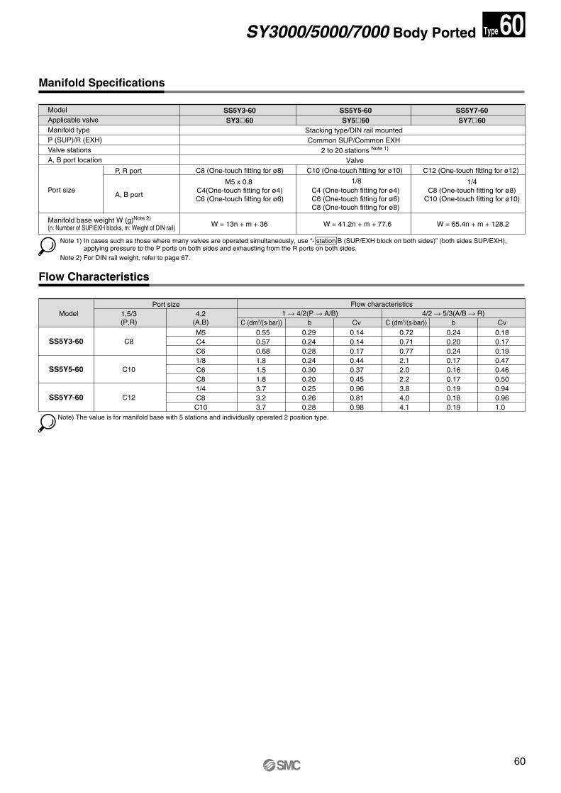
How to Order Valve Manifold Assembly (Example)
Example
P port C8: With one-touch fitting for ø8
R port C8: With one-touch fitting for ø8
Manifold base (4 stations)SS5Y3-60-04U
Single solenoid (24 VDC)SY3160-5G-M5 (2 sets)
Double solenoid (24 VDC)SY3260-5G-C6 (2 sets)
Cylinder port size M5: M5 x 0.8
Cylinder port size C6: With one-touch fitting for ø6
U side
D side
SY3000SY5000SY7000
357
The asterisk denotes the symbol for assembly. Prefix it to the part nos. of the solenoid valve, etc.
P
12
n Stations
R
+–
+–
60Type
When a DIN rail longer than standard is required, enter the number of manifold stations that corresponds with the length of DIN rail needed.Max. 20 stations
∗ For special specifications, indicate separately by the manifold specification sheet.
SS5Y3-60-04U 1 set (Type 60, 4 station manifold base part no.)∗ SY3260-5G-C6 2 sets (Double solenoid part no.)∗ SY3160-5G-M5 2 sets (Single solenoid part no.)
Add the valve and option part number under the manifold base part number. In the case of complex arrangement, specify them on the manifold specification sheet.
UDB
M*
SY.qxd 03.11.11 8:37 AM Page 59
60
Manifold Specifications
Model Applicable valve Manifold type P (SUP)/R (EXH) Valve stations A, B port location
Port size
P, R port
A, B port
SS5Y3-60SY3�60
C8 (One-touch fitting for ø8)
M5 x 0.8 C4(One-touch fitting for ø4)C6 (One-touch fitting for ø6)
SS5Y5-60SY5�60
C10 (One-touch fitting for ø10)
C4 (One-touch fitting for ø4)C6 (One-touch fitting for ø6)C8 (One-touch fitting for ø8)
Stacking type/DIN rail mounted Common SUP/Common EXH
2 to 20 stations Note 1)
Valve
W = 13n + m + 36 W = 41.2n + m + 77.6
SS5Y7-60SY7�60
C12 (One-touch fitting for ø12)
1/4C8 (One-touch fitting for ø8)
C10 (One-touch fitting for ø10)
W = 65.4n + m + 128.2
Flow Characteristics
Manifold base weight W (g)Note 2)
(n: Number of SUP/EXH blocks, m: Weight of DIN rail)
ModelFlow characteristics
0.550.570.681.81.51.83.73.23.7
M5C4C61/8C6C81/4C8
C10
0.290.240.280.240.300.200.250.260.28
0.140.140.170.440.370.450.960.810.98
0.720.710.772.12.02.23.84.04.1
0.240.200.240.170.160.170.190.180.19
0.180.170.190.470.460.500.940.961.0
1 � 4/2(P � A/B) 4/2 � 5/3(A/B � R)Port size
Note) The value is for manifold base with 5 stations and individually operated 2 position type.
SS5Y3-60
SS5Y5-60
SS5Y7-60
C8
C10
C12
C (dm3/(s·bar)) b Cv C (dm3/(s·bar)) b Cv1,5/3(P,R)
4,2(A,B)
SY3000/5000/7000 Body Ported 60Type
1/8
Note 1) In cases such as those where many valves are operated simultaneously, use “- station B (SUP/EXH block on both sides)” (both sides SUP/EXH), applying pressure to the P ports on both sides and exhausting from the R ports on both sides.
Note 2) For DIN rail weight, refer to page 67.
SY.qxd 03.11.11 8:37 AM Page 60
61
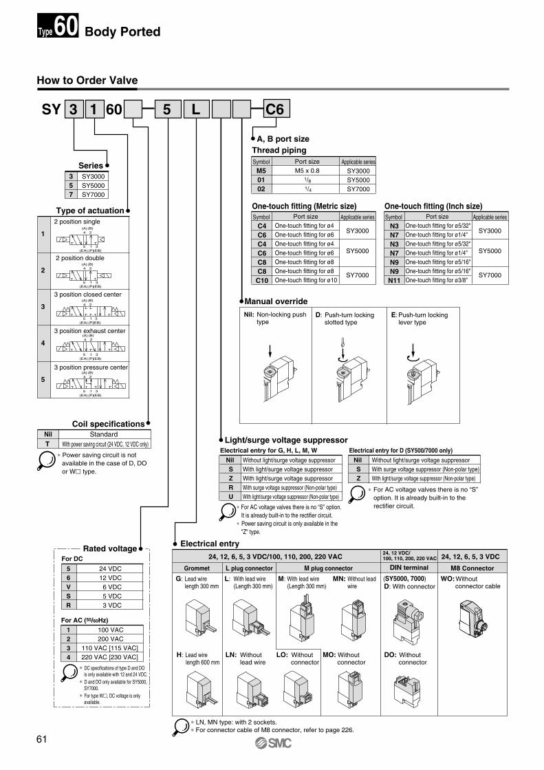
How to Order Valve
1
2
3
4
5
2 position single
2 position double
3 position closed center
3 position exhaust center
3 position pressure center
Type of actuation
A, B port sizeThread piping
Manual override
Rated voltage
Light/surge voltage suppressor
Electrical entry
24, 12, 6, 5, 3 VDC/100, 110, 200, 220 VAC
M plug connectorL plug connector
24, 12, 6, 5, 3 VDC
M8 ConnectorGrommet
1234
100 VAC200 VAC
110 VAC [115 VAC] 220 VAC [230 VAC]
56VSR
24 VDC12 VDC6 VDC5 VDC3 VDC
(50/60Hz)
For DC
For AC
SeriesSY3000SY5000SY7000
357
SymbolM50102
Port size M5 x 0.8
1/8
1/4
Applicable seriesSY3000SY5000SY7000
Nil SZRU
Without light/surge voltage suppressor With light/surge voltage suppressor With light/surge voltage suppressor With surge voltage suppressor (Non-polar type)With light/surge voltage suppressor (Non-polar type)
Electrical entry for G, H, L, M, W
Nil SZ
Without light/surge voltage suppressor With surge voltage suppressor (Non-polar type)With light/surge voltage suppressor (Non-polar type)
Electrical entry for D (SY500/7000 only)
24, 12 VDC/100, 110, 200, 220 VAC
DIN terminal
D: With connector(SY5000, 7000)
(A)4
(B)2
5(EA)
3 (EB)
1(P)
(A)4
(B)2
5(EA)
3 (EB)
1(P)
(A)4
(B)2
5(EA)
3 (EB)
1(P)
(A)4
(B)2
5(EA)
3 (EB)
1(P)
(A)4
(B)2
5(EA)
3 (EB)
1(P)
One-touch fitting (Metric size)Symbol
C4C6C4C6C8C8C10
Applicable series
SY3000
SY5000
SY7000
Port sizeOne-touch fitting for ø4One-touch fitting for ø6One-touch fitting for ø4One-touch fitting for ø6One-touch fitting for ø8 One-touch fitting for ø8 One-touch fitting for ø10
One-touch fitting (Inch size)Symbol
N3N7N3N7N9N9N11
Applicable series
SY3000
SY5000
SY7000
Port size One-touch fitting for ø5/32" One-touch fitting for ø1/4" One-touch fitting for ø5/32" One-touch fitting for ø1/4"One-touch fitting for ø5/16"One-touch fitting for ø5/16"One-touch fitting for ø3/8"
∗ For AC voltage valves there is no “S” option. It is already built-in to the rectifier circuit.
∗ Power saving circuit is only available in the "Z" type.
∗ For AC voltage valves there is no “S” option. It is already built-in to the rectifier circuit.
- +
- +
+-
-+-+
+-
∗ Power saving circuit is not available in the case of D, DO or W� type.
Coil specificationsStandard
With power saving circuit (24 VDC, 12 VDC only) NilT
∗ DC specifications of type D and DO is only available with 12 and 24 VDC.
∗ D and DO only available for SY5000, SY7000.
∗ For type W�, DC voltage is only available.
∗ LN, MN type: with 2 sockets.∗ For connector cable of M8 connector, refer to page 226.
Body Ported60Type
SY 3 1 60 5 L C6
Nil: Non-locking push type
D: Push-turn locking slotted type
E:Push-turn locking lever type
G: Lead wire length 300 mm
L: With lead wire (Length 300 mm)
M: With lead wire (Length 300 mm)
MN: Without lead wire
WO:Without connector cable
H: Lead wire length 600 mm
LN: Without lead wire
LO: Without connector
MO: Without connector
DO: Without connector
SY.qxd 03.11.11 8:37 AM Page 61
62
Specifications
Solenoid Specifications
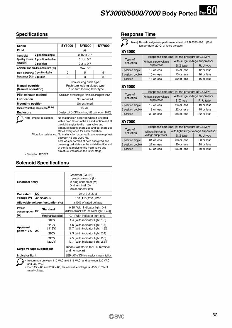
Response Time
Fluid
Internal pilotOperating pressure range (MPa)
Ambient and fluid temperature (°C)
Max. operating frequency (Hz)
Manual override (Manual operation)
Pilot exhaust method
Lubrication
Mounting position
Impact/Vibration resistance Note)
Enclosure
2 position single
2 position double
3 position
2 position double
3 position
Air
0.15 to 0.7
0.1 to 0.7
0.2 to 0.7
Max. 50
Common exhaust type for main and pilot valve
Not required
Unrestricted
150/30
Dust proof (∗ DIN terminal, M8 connector: IP65)
Non-locking push type, Push-turn locking slotted type,Push-turn locking lever type
Electrical entry
Coil rated voltage (V)
Allowable voltage fluctuation (%)
Standard
With power saving circuit
Power consumption (W)
Apparent power∗ VA
Surge voltage suppressor
Indicator light
DC
AC 50/60Hz
AC
100V
110V [115V]
200V
220V [230V]
Grommet (G), (H)L plug connector (L)M plug connector (M)DIN terminal (D)M8 connector (W)
24 ,12 ,6 ,5 ,3
100 ,110 ,200 ,220∗
2.5 (With indicator light: 2.6)[2.7 (With indicator light: 2.8)]
Type of actuation
2 position single
2 position double
3 position
Response time (ms) (at the pressure of 0.5 MPa)
Without surge voltage suppressor
With surge voltage suppressor
DC
Series SY3000 SY7000
10
3
5
3
SY5000
5
3
SY3000
12 or less
10 or less
15 or less
S, Z type
15 or less
13 or less
20 or less
R, U type
12 or less
10 or less
16 or less
Type of actuation
2 position single
2 position double
3 position
Response time (ms) (at the pressure of 0.5 MPa)
Without surge voltage suppressor
With surge voltage suppressor
SY5000
19 or less
18 or less
32 or less
S, Z type
26 or less
22 or less
38 or less
R, U type
19 or less
18 or less
32 or less
1.6 (With indicator light: 1.7)[1.7 (With indicator light: 1.8)]
2.3 (With indicator light: 2.4)
1.4 (With indicator light: 1.5)
0.1 (With indicator light only)
0.35 [With indicator light: 0.4 (DIN terminal with indicator light: 0.45)]
LED (AC of DIN connector is neon light.)
Type of actuation
2 position single
2 position double
3 position
Response time (ms) (at the pressure of 0.5 MPa)
Without light/surge voltage suppressor
With light/surge voltage suppressor
SY7000
31 or less
27 or less
50 or less
S, Z type
38 or less
30 or less
56 or less
R, U type
33 or less
28 or less
50 or less
±10% of rated voltage
Note) Impact resistance: No malfunction occurred when it is tested with a drop tester in the axial direction and at the right angles to the main valve and armature in both energized and de-energized states every once for each condition.
Vibration resistance: No malfunction occurred in a one-sweep test between 45 and 2000 Hz. Test was performed at both energized and de-energized states in the axial direction and at the right angles to the main valve and armature. (Values in the initial stage)
∗ Based on IEC529
Note) Based on dynamic performance test, JIS B 8375-1981. (Coil temperature: 20°C, at rated voltage)
∗ In common between 110 VAC and 115 VAC, and between 220 VAC and 230 VAC.
∗ For 115 VAC and 230 VAC, the allowable voltage is -15% to 5% of rated voltage.
Diode (Varistor is for DIN terminal and non-polar)
SY3000/5000/7000 Body Ported 60Type
SY.qxd 03.11.11 8:38 AM Page 62
63
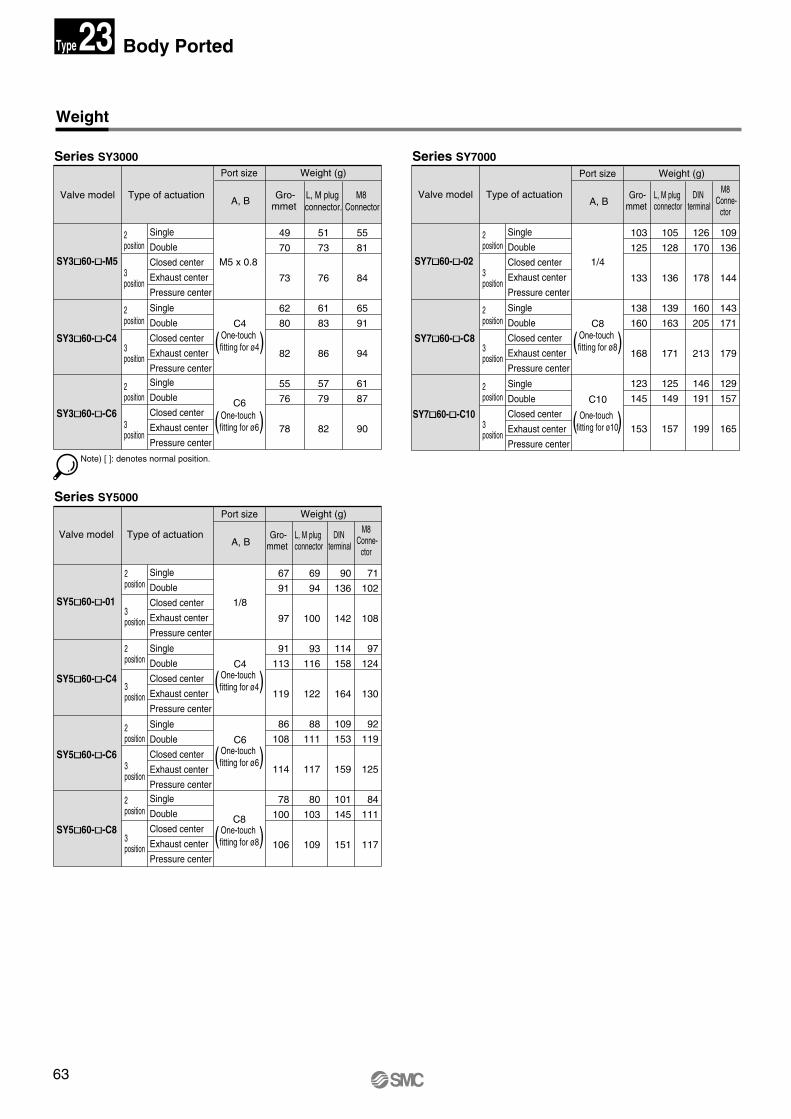
Weight
Valve model Type of actuation
2 position
3 position
2 position
3 position
2 position
3 position
2 position
3 position
2 position
3 position
2 position
3 position
2 position
3 position
2 position
3 position
2 position
3 position
2 position
3 position
Single
Double
Closed center
Exhaust center
Pressure center
Single
Double
Closed center
Exhaust center
Pressure centerSingle
Double
Closed center
Exhaust center
Pressure center
51
73
76
61
83
86
57
79
82
49
70
73
62
80
82
55
76
78
M5 x 0.8
C6One-touch fitting for ø6( )
One-touch fitting for ø4( )
One-touch fitting for ø6( )
One-touch fitting for ø8( )
C4One-touch fitting for ø4( )
One-touch fitting for ø10( )
One-touch fitting for ø8( )
Gro-mmet
L, M plug connector.
55
81
84
65
91
94
61
87
90
M8 Connector
Note) [ ]: denotes normal position.
Single
Double
Closed center
Exhaust center
Pressure center
Single
Double
Closed center
Exhaust center
Pressure centerSingle
Double
Closed center
Exhaust center
Pressure center
69
94
100
93
116
122
88
111
117
80
103
109
67
91
97
91
113
119
86
108
114
78
100
106
1/8
C8
C6
Series SY3000
Series SY5000
71
102
108
97
124
130
92
119
125
84
111
117
90
136
142
114
158
164
109
153
159
101
145
151
SY3�60-�-M5
SY3�60-�-C4
SY3�60-�-C6
SY5�60-�-01
SY5�60-�-C6
SY5�60-�-C8
Single
Double
Closed center
Exhaust center
Pressure center
C4
SY5�60-�-C4
Valve model Type of actuation
Single
Double
Closed center
Exhaust center
Pressure center
Single
Double
Closed center
Exhaust center
Pressure center
105
128
136
139
163
171
125
149
157
103
125
133
138
160
168
123
145
153
1/4
C10
Gro-mmet
L, M plug connector
Series SY7000
109
136
144
143
171
179
129
157
165
126
170
178
160
205
213
146
191
199
DIN terminal
M8 Conne-
ctor
SY7�60-�-02
SY7�60-�-C10
Single
Double
Closed center
Exhaust center
Pressure center
C8
SY7�60-�-C8
Valve model Type of actuation
Port size
A, BGro-
mmet L, M plug connector
DIN terminal
M8 Conne-
ctor
Weight (g)
Port size
A, B
Weight (g) Port size
A, B
Weight (g)
Body Ported23Type
SY.qxd 03.11.11 8:38 AM Page 63
64
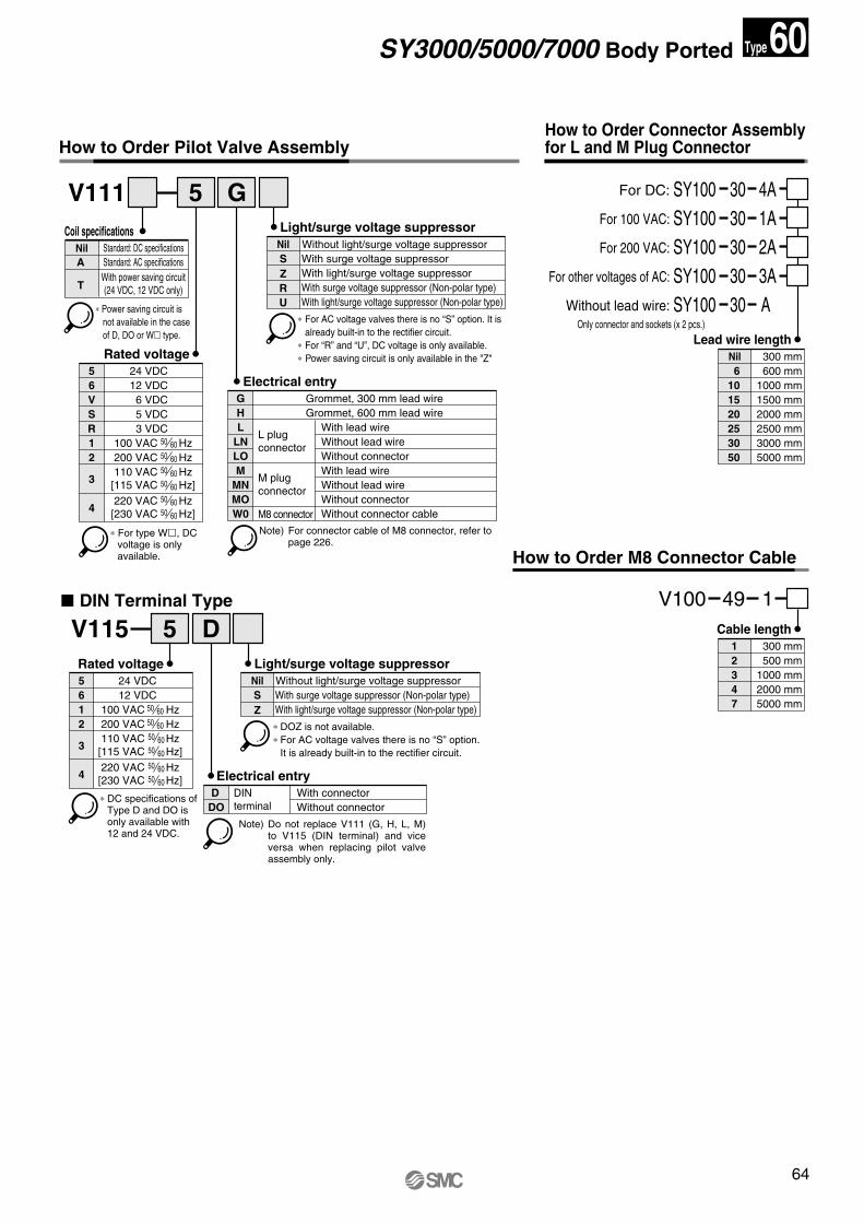
How to Order Pilot Valve AssemblyHow to Order Connector Assemblyfor L and M Plug Connector
5 GV111
5 24 VDC6 12 VDCV 6 VDCS 5 VDCR 3 VDC1 100 VAC Hz2 200 VAC Hz
3
4 220 VAC Hz [230 VAC Hz]
50 6050 60
110 VAC Hz [115 VAC Hz]
50 60
50 60
50 60
50 60
Nil Without light/surge voltage suppressorSZ
With surge voltage suppressorWith light/surge voltage suppressor
R With surge voltage suppressor (Non-polar type)U With light/surge voltage suppressor (Non-polar type)
G Grommet, 300 mm lead wireH Grommet, 600 mm lead wireL With lead wire
L plug connector
M plug connector
LN Without lead wireLO Without connector
With lead wireWithout lead wireWithout connector
MMNMO
M8 connector Without connector cableW0
∗ For AC voltage valves there is no “S” option. It is already built-in to the rectifier circuit.
∗ For “R” and “U”, DC voltage is only available.∗ Power saving circuit is only available in the "Z" Rated voltage
Electrical entry
Light/surge voltage suppressor
Note) For connector cable of M8 connector, refer to page 226.
Nil
101520253050
300 mm
1000 mm6 600 mm
1500 mm2000 mm2500 mm3000 mm5000 mm
30 4ASY100For DC:
30 1ASY100For 100 VAC:
30 2ASY100For 200 VAC:
30 3ASY100For other voltages of AC:
30 A SY100Without lead wire:Only connector and sockets (x 2 pcs.)
Lead wire length
5 DV115
5 24 VDC6 12 VDC1 100 VAC Hz2 200 VAC Hz
3
4 220 VAC Hz [230 VAC Hz]
50 6050 60
110 VAC Hz [115 VAC Hz]
50 60
50 60
50 60
50 60
DIN terminal
D With connectorDO Without connector
Nil Without light/surge voltage suppressorSZ
With surge voltage suppressor (Non-polar type)With light/surge voltage suppressor (Non-polar type)
∗ DOZ is not available.∗ For AC voltage valves there is no “S” option.
It is already built-in to the rectifier circuit.
Rated voltage
Electrical entry
Light/surge voltage suppressor
How to Order M8 Connector Cable
1
347
300 mm
1000 mm2 500 mm
2000 mm5000 mm
49 1V100Cable length
Standard: DC specificationsNil
TWith power saving circuit (24 VDC, 12 VDC only)
A Standard: AC specifications
Coil specifications
∗ For type W�, DC voltage is only available.
∗ DC specifications of Type D and DO is only available with 12 and 24 VDC.
∗ Power saving circuit is not available in the case of D, DO or W� type.
� DIN Terminal Type
Note) Do not replace V111 (G, H, L, M) to V115 (DIN terminal) and vice versa when replacing pilot valve assembly only.
SY3000/5000/7000 Body Ported 60Type
SY.qxd 03.11.11 8:38 AM Page 64
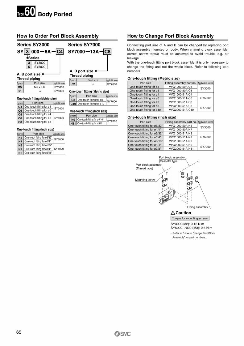
65
How to Change Port Block Assembly
Connecting port size of A and B can be changed by replacing port block assembly mounted on body. When changing block assembly, correct screw torque must be achieved to avoid trouble; e.g. air leakage.With the one-touch fitting port block assembly, it is only necessary to change the fitting and not the whole block. Refer to following part numbers.
Torque for mounting screws
SY3000(M2): 0.12 N·m SY5000, 7000 (M3): 0.6 N·m
How to Order Port Block Assembly
SY 3 000 6ASeries
SY3000SY5000
35
A, B port sizeOne-touch fitting (Metric size)
Caution
A, B port size
C4 SY7000 13ASeries SY3000 Series SY7000
C8
Thread pipingSymbolM5 01
Port size M5 x 0.8
1/8
Applicable seriesSY3000SY5000
One-touch fitting (Metric size)SymbolC4C6C4C6C8
Applicable series
SY3000
SY5000
Port size One-touch fitting for ø4 One-touch fitting for ø6 One-touch fitting for ø4 One-touch fitting for ø6 One-touch fitting for ø8
One-touch fitting (Inch size)SymbolN3N7N3N7N9
Applicable series
SY3000
SY5000
Port sizeOne-touch fitting for ø5/32"One-touch fitting for ø1/4"One-touch fitting for ø5/32"One-touch fitting for ø1/4"One-touch fitting for ø5/16"
Applicable series
SY3000
SY5000
SY7000
Port sizeOne-touch fitting for ø4One-touch fitting for ø6One-touch fitting for ø4One-touch fitting for ø6One-touch fitting for ø8 One-touch fitting for ø8 One-touch fitting for ø10
Fitting assembly part no.VVQ1000-50A-C4VVQ1000-50A-C6VVQ1000-51A-C4VVQ1000-51A-C6VVQ1000-51A-C8VVQ2000-51A-C8VVQ2000-51A-C10
One-touch fitting (Inch size)Applicable series
SY3000
SY5000
SY7000
Port sizeOne-touch fitting for ø5/32"One-touch fitting for ø1/4"One-touch fitting for ø5/32"One-touch fitting for ø1/4"One-touch fitting for ø5/16"One-touch fitting for ø1/4"One-touch fitting for ø3/8"
Fitting assembly part no. VVQ1000-50A-N3 VVQ1000-50A-N7VVQ1000-51A-N3VVQ1000-51A-N7VVQ1000-51A-N9VVQ2000-51A-N9VVQ2000-51A-N11
Thread pipingSymbol02
Port size1/4
Applicable seriesSY7000
One-touch fitting (Metric size)SymbolC8
C10
Applicable series
SY7000
Port sizeOne-touch fitting for ø8One-touch fitting for ø10
One-touch fitting (Inch size)SymbolN9
N11
Applicable series
SY7000
Port sizeOne-touch fitting for ø5/16"One-touch fitting for ø3/8"
Port block assembly (Cassette type)
Port block assembly (Thread type)
Mounting screw
Fitting assembly
∗ Refer to “How to Change Port Block
Assembly” for part numbers.
Body Ported60Type
SY.qxd 03.11.11 8:38 AM Page 65
66
U side
D side
R portPlug
Blocking disk
P
R
U side
D side
(P port)
Blocking diskP
P
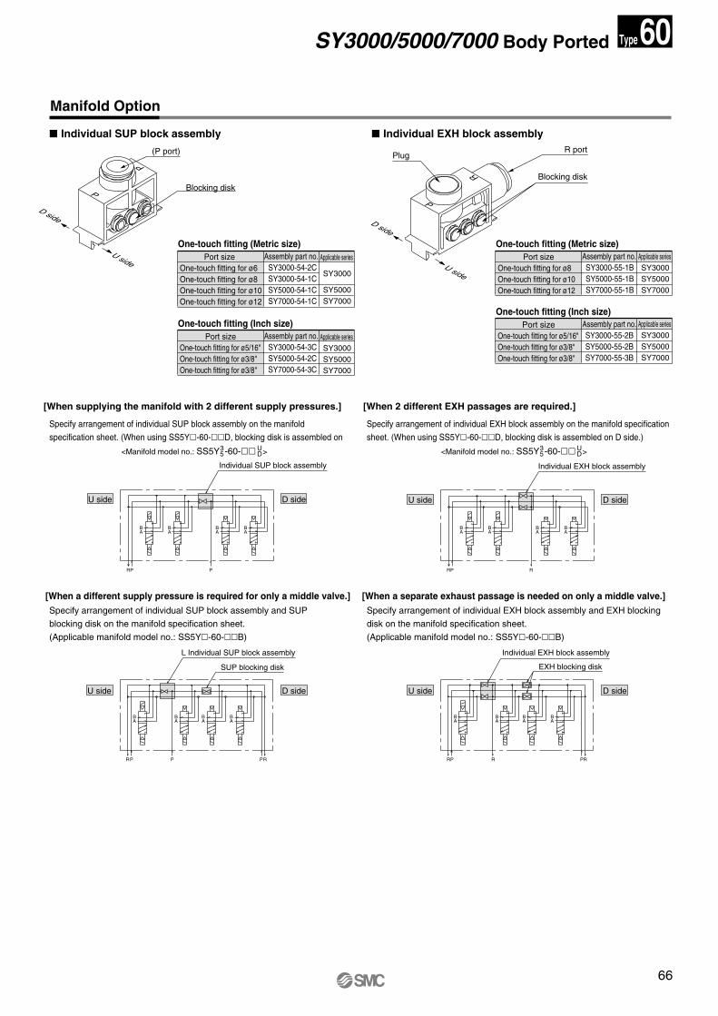
Manifold Option
� Individual SUP block assembly � Individual EXH block assembly
Individual SUP block assembly
U side D side
BA
BA
BA
BA
PPR
SUP blocking disk
L Individual SUP block assembly
U side D side
BA
BA
BA
BA
PPR PR
EXH blocking disk
Individual EXH block assembly
U side D side
U side D side
BA
BA
BA
BA
RPR PR
Individual EXH block assembly
BA
BA
BA
BA
RPR
[When supplying the manifold with 2 different supply pressures.]
<Manifold model no.: SS5Y -60-�� >UD5
3 <Manifold model no.: SS5Y -60-�� >UD5
3
[When a different supply pressure is required for only a middle valve.] [When a separate exhaust passage is needed on only a middle valve.]
[When 2 different EXH passages are required.]
One-touch fitting (Metric size)Applicable series
SY3000
SY5000 SY7000
Assembly part no. SY3000-54-2CSY3000-54-1CSY5000-54-1CSY7000-54-1C
Port size One-touch fitting for ø6 One-touch fitting for ø8 One-touch fitting for ø10 One-touch fitting for ø12
One-touch fitting (Inch size)Applicable series SY3000SY5000SY7000
Assembly part no. SY3000-54-3CSY5000-54-2CSY7000-54-3C
Port sizeOne-touch fitting for ø5/16"One-touch fitting for ø3/8"One-touch fitting for ø3/8"
One-touch fitting (Metric size)Assembly part no.SY3000-55-1BSY5000-55-1BSY7000-55-1B
Port sizeOne-touch fitting for ø8One-touch fitting for ø10One-touch fitting for ø12
One-touch fitting (Inch size)Assembly part no.SY3000-55-2BSY5000-55-2BSY7000-55-3B
Port sizeOne-touch fitting for ø5/16" One-touch fitting for ø3/8"One-touch fitting for ø3/8"
Applicable series SY3000SY5000SY7000
Applicable series SY3000SY5000SY7000
Specify arrangement of individual SUP block assembly on the manifold
specification sheet. (When using SS5Y�-60-��D, blocking disk is assembled on
Specify arrangement of individual SUP block assembly and SUP
blocking disk on the manifold specification sheet.
(Applicable manifold model no.: SS5Y�-60-��B)
Specify arrangement of individual EXH block assembly and EXH blocking
disk on the manifold specification sheet.
(Applicable manifold model no.: SS5Y�-60-��B)
Specify arrangement of individual EXH block assembly on the manifold specification
sheet. (When using SS5Y�-60-��D, blocking disk is assembled on D side.)
SY3000/5000/7000 Body Ported 60Type
SY.qxd 03.11.11 8:38 AM Page 66
67
Manifold Option
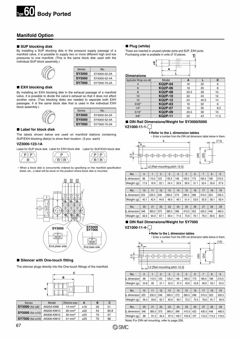
� SUP blocking disk
� EXH blocking disk
� Label for block disk
� Silencer with One-touch fitting
� Plug (white)
Label for SUP block disk Label for EXH block disk Label for SUP/EXH block disk
By installing a SUP blocking disk in the pressure supply passage of a manifold valve, it is possible to supply two or more different high and low pressures to one manifold. (This is the same block disk used with the individual SUP block assembly.)
The labels shown below are used on manifold stations containing SUP/EXH blocking disk(s) to show their location. (3 pcs. each)
By installing an EXH blocking disk in the exhaust passage of a manifold valve, it is possible to divide the valve’s exhaust so that it does not affect another valve. (Two blocking disks are needed to separate both EXH passages. It is the same block disk that is used in the individual EXH block assembly.)
VZ3000-123-1A
PR
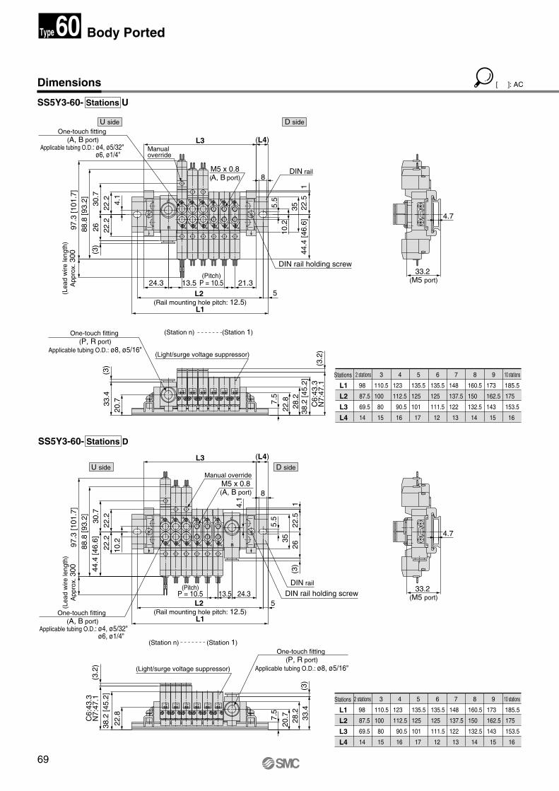
PR
PR
PR
PR
The silencer plugs directly into the One-touch fittings of the manifold.
These are inserted in unused cylinder ports and SUP, EXH ports.Purchasing order is available in units of 10 pieces.
Applicable fittings size ød468
1012
5/32"1/4"
5/16"3/8"
KQ2P-04KQ2P-06KQ2P-08KQ2P-10KQ2P-12KQ2P-03KQ2P-07KQ2P-09KQ2P-11
Model A L D161820.52224161820.522
3235394345.532353943
6 8101214 6 8.51011.5
� DIN Rail Dimensions/Weight for SY3000/5000
No.
L dimension
Weight (g)
98
17.6
110.5
19.9
123
22.1
135.5
24.4
148
26.6
160.5
28.9
173
31.1
185.5
33.4
198
35.6
210.5
37.9
No.
L dimension
Weight (g)
223
40.1
235.5
42.4
248
44.6
260.5
46.9
273
49.1
285.5
51.4
298
53.6
310.5
55.9
323
58.1
335.5
60.4
No.
L dimension
Weight (g)
348
62.6
360.5
64.9
373
67.1
385.5
69.4
398
71.6
410.5
73.9
423
76.1
435.5
78.4
448
80.6
460.5
82.9
VZ1000-11-1-
Refer to the L dimension tables∗ Enter a number from the DIN rail dimension table below in them.
Dimensions
øD
L
A
ød
(7.5)
(25
)
(35
)
(10)
(24
)
(35
)
L8
5.5
L2 [Rail mounting pitch 12.5]
L8
5.5
L2 [Rail mounting pitch 12.5]
� DIN Rail Dimensions/Weight for SY7000
No.
L dimension
Weight (g)
98
24.8
110.5
28
123
31.1
135.5
34.3
148
37.4
160.5
40.6
173
43.8
185.5
46.9
198
50.1
210.5
53.3
No.
L dimension
Weight (g)
223
56.4
235.5
59.6
248
62.7
260.5
65.9
273
69.1
285.5
72.2
298
75.4
310.5
78.6
323
81.7
335.5
84.9
No.
L dimension
Weight (g)
Note) For DIN rail mounting, refer to page 226.
348
88
360.5
91.2
373
94.4
385.5
97.5
398
100.7
410.5
103.9
423
107
435.5
110.2
448
113.3
460.5
116.5
VZ1000-11-4-
Refer to the L dimension tables∗ Enter a number from the DIN rail dimension table below in them.
Series
SY3000SY5000SY7000
No.
SY3000-52-2A
SY5000-52-4A
SY7000-70-2A
Series
SY3000SY5000SY7000
No.
SY3000-52-2A
SY5000-52-4A
SY7000-70-2A
Series SY3000 (for ø8)
SY5000 (for ø10)
SY7000 (for ø12)
ModelAN203-KM8 AN200-KM10 AN300-KM10 AN300-KM12
Effective area 14 mm2
26 mm2
30 mm2
41 mm2
B26547070
C5180.89798
A ø16ø22ø25ø25
A
C
B
RRP
A
BA A
B
R
P
PR R
SY3000
PR R
SY7000SY5000
End plate side End plate side
∗ When a block disk is concurrently ordered by specifying on the manifold specification sheet, etc., a label will be stuck on the position where block disk is mounted.
0 1 2 3 4 5 6 7 8 9
10 11 12 13 14 15 16 17 18 19
20 21 22 23 24 25 26 27 28 29
0 1 2 3 4 5 6 7 8 9
10 11 12 13 14 15 16 17 18 19
20 21 22 23 24 25 26 27 28 29
Body Ported60Type
SY.qxd 03.11.11 8:38 AM Page 67
68
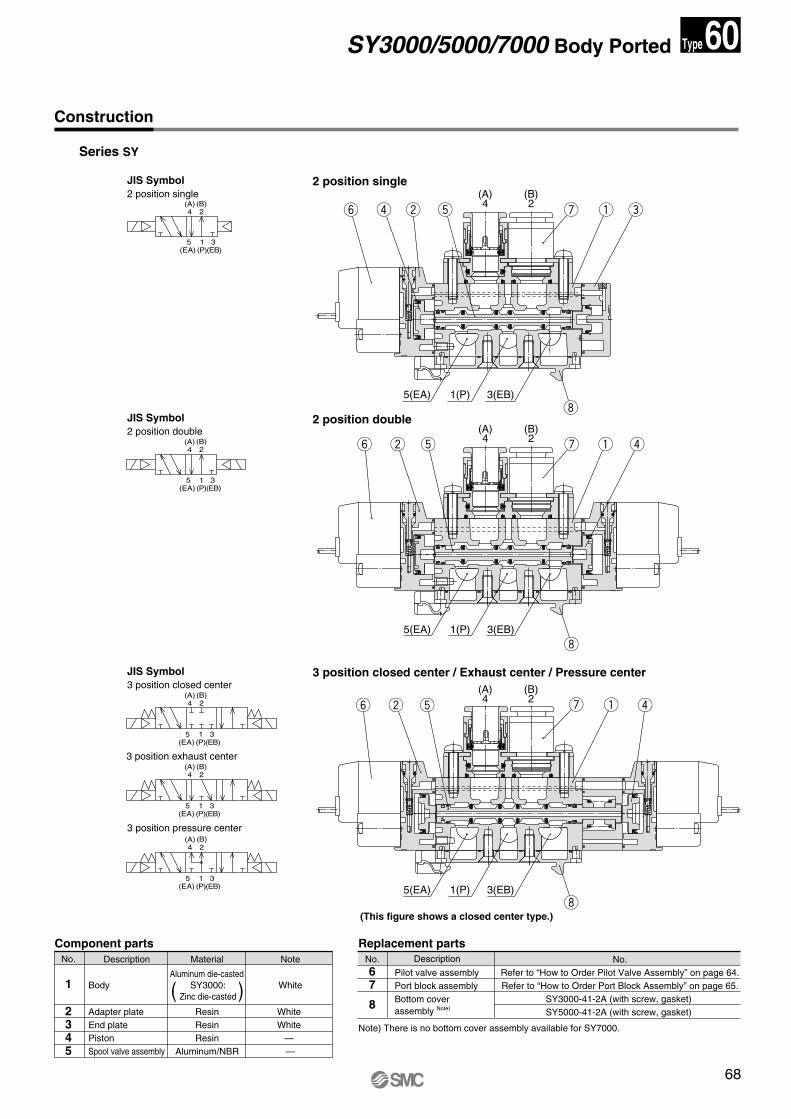
Construction
Series SY
2 position single
2 position double
3 position closed center / Exhaust center / Pressure center
(This figure shows a closed center type.)
JIS Symbol 2 position single
JIS Symbol 2 position double
JIS Symbol 3 position closed center
3 position exhaust center
3 position pressure center
( )
No. Description Material
Component partsNote
1 Body White
2345
Adapter plateEnd platePistonSpool valve assembly
ResinResinResin
Aluminum/NBR
White White
— —
Aluminum die-casted SY3000:
Zinc die-casted
No.67
8
Pilot valve assembly Port block assembly Bottom cover assembly Note)
No.Refer to “How to Order Pilot Valve Assembly” on page 64.Refer to “How to Order Port Block Assembly” on page 65.
SY3000-41-2A (with screw, gasket) SY5000-41-2A (with screw, gasket)
Replacement parts
(A)4
(B)2
5(EA)
3 (EB)
1(P)
(A)4
(B)2
5(EA)
3 (EB)
1(P)
(A)4
(B)2
5(EA)
3 (EB)
1(P)
(A)4
(B)2
5(EA)
3 (EB)
1(P)
(A)4
(B)2
5(EA)
3 (EB)
1(P)
Note) There is no bottom cover assembly available for SY7000.
(B)2
(A)4
3(EB)1(P)5(EA)
(B)2
(A)4
3(EB)1(P)5(EA)
(B)2
(A)4
3(EB)1(P)5(EA)
q eur wy
i
i
t
q ruwy
i
t
q ruwy t
Description
SY3000/5000/7000 Body Ported 60Type
SY.qxd 03.11.11 8:38 AM Page 68
69
Dimensions
SS5Y3-60- Stations U
SS5Y3-60- Stations D
Stations
L1
L2
L3
L4
98
87.5
69.5
14
110.5
100
80
15
123
112.5
90.5
16
135.5
125
101
17
135.5
125
111.5
12
148
137.5
122
13
160.5
150
132.5
14
173
162.5
143
15
185.5
175
153.5
16
Stations
L1
L2
L3
L4
98
87.5
69.5
14
110.5
100
80
15
123
112.5
90.5
16
135.5
125
101
17
135.5
125
111.5
12
148
137.5
122
13
160.5
150
132.5
14
173
162.5
143
15
185.5
175
153.5
16
13.5
(3.2
)C
6:43
.3N
7:47
.1
One-touch fitting (A, B port)
Applicable tubing O.D.: ø4, ø5/32" ø6, ø1/4"
Manual overrideM5 x 0.8(A, B port)
DIN rail holding screwDIN rail
(Station n)
(Light/surge voltage suppressor)
(Station 1)One-touch fitting
(P, R port)Applicable tubing O.D.: ø8, ø5/16"
97.3
[101
.7]
88.8
[93.
2]44
.4 [4
6.6]
1
38.2
[45.
2]30
.722
.222
.2
(3)
33.4
28.2
20.7
22.8
(3.2
)
(3)
26
C6:
43.3
N7:
47.1
L1
L2 (Rail mounting hole pitch: 12.5)
22.5
33.2 (M5 port)
10.2
(L4)L3
4.7
5
35
(Pitch)P = 10.5 13.5 24.3
8
4.1
5.5
1
5.5
28.2
38.2
[45.
2]44
.4 [4
6.6]
97.3
[101
.7]
88.8
[93.
2]
22.8
DIN rail holding screw
22.5
L1
2630
.722
.222
.2 4.1
Manual override
(Pitch)P = 10.5 21.3
One-touch fitting (A, B port)
Applicable tubing O.D.: ø4, ø5/32" ø6, ø1/4"
(3)
One-touch fitting (P, R port)
Applicable tubing O.D.: ø8, ø5/16"
(3)
3510
.224.3
5L2 (Rail mounting hole pitch: 12.5)
33.4
20.7
33.2 (M5 port)
(L4)L3
M5 x 0.8(A, B port)
DIN rail
(Station n)
(Light/surge voltage suppressor)
D sideU side
(Station 1)
4.7
8
R
P
+-+-+- +-+-
A
B
A
B
A
B
A
B
A
B
A
B
A
B
A
B
A
B
A
B
A
B
A
B
R
P
+- +-+-
+-
+- +- +-
7.5
7.5
(Lea
d w
ire le
ngth
)A
ppro
x. 3
00(L
ead
wire
leng
th)
App
rox.
300
D sideU side
[ ]: AC
2 stations 3 4 5 6 7 8 9 10 stations
2 stations 3 4 5 6 7 8 9 10 stations
Body Ported60Type
SY.qxd 03.11.11 8:38 AM Page 69
70
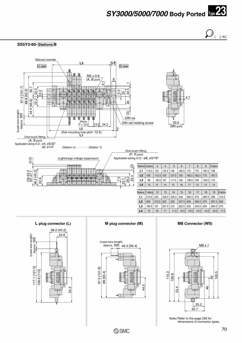
Stations
L1
L2
L3
L4
2 stations
110.5
100
86
12
3
123
112.5
96.5
13
4
135.5
125
107
14
5
148
137.5
117.5
15
6
160.5
150
128
16
7
173
162.5
138.5
17
8
173
162.5
149
12
9
185.5
175
159.5
13
10 stations
198
187.5
170
14
Stations
L1
L2
L3
L4
11 stations
210.5
200
180.5
15
12
223
212.5
191
16
13
235.5
225
201.5
17
14
235.5
225
212
11.5
15
248
237.5
222.5
12.5
16
260.5
250
233
13.5
17
273
262.5
243.5
14.5
19
298
287.5
264.5
16.5
20 stations
310.5
300
275
17.5
18
285.5
275
254
15.5
L plug connector (L) M plug connector (M) M8 Connector (W0)
SS5Y3-60- Stations B
97.5
[101
.9]
89 [9
3.4]
117.
1 [1
21.5
]
108.
6 [1
13]
(Lea
d w
ire le
ngth
)A
ppro
x. 3
00
22.8
38.2 [45.2]
54.3 44
.5
49.3 [56.3]
351
(3)
26
44.4
[46.
6]88
.8 [9
3.2]
97.3
[101
.7]
(3.2
)
38.2
[45.
2]
C6:
43.3
N7:
47.1
22.8
5
(Pitch)P = 10.5 24.313.5L2
(Rail mounting hole pitch: 12.5)L1
DIN rail holding screw
DIN rail
22.530
.7
22.2
22.2
10.2
One-touch fitting (A, B port)
Applicable tubing O.D.: ø4, ø5/32" ø6, ø1/4"
L3
33.2 (M5 port)
(L4)Manual override
M5 x 0.8(A, B port)
(Station n)
(Light/surge voltage suppressor)
D sideU side
(Station 1)One-touch fitting
(P, R port)Applicable tubing O.D.: ø8, ø5/16"
4.7
8
4.1
5.5
(3)
33.4
28.2
20.7
R
P
+-+-+- +-+- +-
R
P
A
BA
B
A
B
A
B
A
B
A
B
7.5
(Lea
d w
ire le
ngth
)A
ppro
x. 3
00
(Lead wire length)Approx. 300 M8 x 1
25.242.7
53.4
106.
811
5.3
100.
592
46
[ ]: AC
Note) Refer to the page 226 for dimensions of connector types.
SY3000/5000/7000 Body Ported 23Type
SY.qxd 03.11.11 8:38 AM Page 70
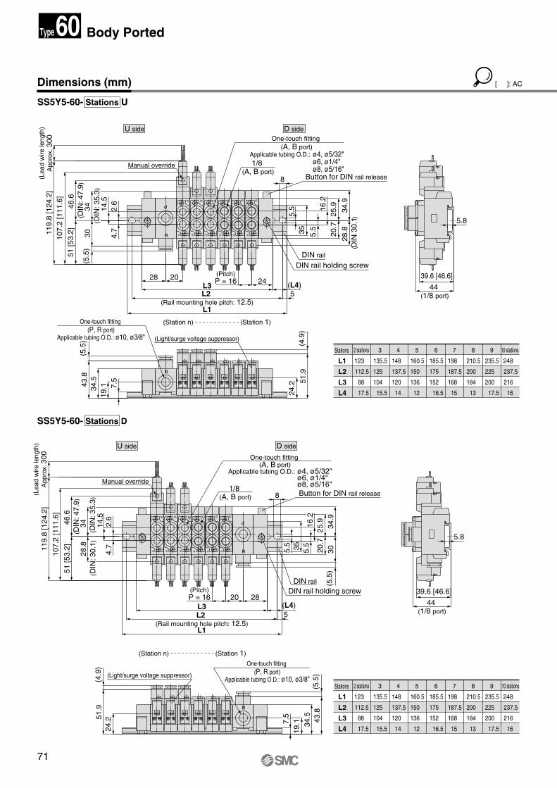
71
Dimensions (mm)
SS5Y5-60- Stations U
SS5Y5-60- Stations D
Stations
L1
L2
L3
L4
2 stations
123
112.5
88
17.5
3
135.5
125
104
15.5
4
148
137.5
120
14
5
160.5
150
136
12
6
185.5
175
152
16.5
7
198
187.5
168
15
8
210.5
200
184
13
9
235.5
225
200
17.5
10 stations
248
237.5
216
16
Stations
L1
L2
L3
L4
2 stations
123
112.5
88
17.5
3
135.5
125
104
15.5
4
148
137.5
120
14
5
160.5
150
136
12
6
185.5
175
152
16.5
7
198
187.5
168
15
8
210.5
200
184
13
9
235.5
225
200
17.5
10 stations
248
237.5
216
16
20
34
(D
IN: 3
5.3)
28
.8 (D
IN: 3
0.1)
51 [5
3.2]
46.6
(D
IN: 4
7.9)
107.
2 [1
11.6
]
119.
8 [1
24.2
]
(5.5
)30
51 [5
3.2]
34
(D
IN: 3
5.3)
46.6
(D
IN: 4
7.9)
107.
2 [1
11.6
]11
9.8
[124
.2]
Button for DIN rail release
DIN rail holding screwDIN rail
Manual override
One-touch fitting (P, R port)
Applicable tubing O.D.: ø10, ø3/8"
1/8 (A, B port)
One-touch fitting (A, B port)
Applicable tubing O.D.: ø4, ø5/32" ø6, ø1/4" ø8, ø5/16"
(Light/surge voltage suppressor)
(Station n) (Station 1)
24.2
(5.5
)30
34.9
(4.9
)51
.9
(5.5
)43
.834
.519
.1
2820(Pitch)P = 16
5(L4)L3
L2 (Rail mounting hole pitch: 12.5)
L1
8
20.7
25.9
5.5355.5
14.5
4.7
2.6
5.8
44 (1/8 port)
39.6 [46.6]
44 (1/8 port)
39.6 [46.6]
28.8
(D
IN: 3
0.1)
5
(Pitch)P = 16 (L4)24
L1
L2 (Rail mounting hole pitch: 12.5)
L328
24.2
(4.9
)51
.9
34.9
Button for DIN rail release
DIN rail holding screwDIN rail
43.8
34.5
19.1
(5.5
)
8
5.8
20.7
25.9
One-touch fitting (P, R port)
Applicable tubing O.D.: ø10, ø3/8"
5.535
5.514
.54.
72.
6
1/8 (A, B port)
One-touch fitting (A, B port)
Applicable tubing O.D.: ø4, ø5/32" ø6, ø1/4"
ø8, ø5/16"Manual override
(Light/surge voltage suppressor)
(Station n) (Station 1)
+-
A
B
+-+-+-
R
P
A
B
R
A
B
A
B
A
B
A
B
+-+-
+- +-+- +- +- +-R
A
B
A
B
A
B
A
B
A
B
A
B
R
P
7.5
7.5
D sideU side
D sideU side
16.2
(Lea
d w
ire le
ngth
)A
ppro
x. 3
00
16.2
(Lea
d w
ire le
ngth
)A
ppro
x. 3
00Body Ported
[ ]: AC
60Type
SY.qxd 03.11.11 8:38 AM Page 71
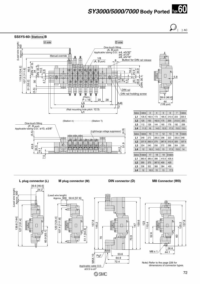
72
Stations
L1
L2
L3
L4
9 stations
248
237.5
224
12
10
273
262.5
240
16.5
11
285.5
275
256
14.5
12
298
287.5
272
13
13
323
312.5
288
17.5
14
335.5
325
304
15.5
15 stations
348
337.5
320
14
Stations
L1
L2
L3
L4
16 stations
360.5
350
336
12
17
385.5
375
352
16.5
19
410.5
400
384
13
20 stations
435.5
425
400
17.5
18
398
387.5
368
15
Stations
L1
L2
L3
L4
2 stations
135.5
125
112
11.5
3
160.5
150
128
16
4
173
162.5
144
14.5
5
185.5
175
160
12.5
6
210.5
200
176
17.5
7
223
212.5
192
15.5
8 stations
235.5
225
208
13.5
SS5Y5-60- Stations B
L plug connector (L) M plug connector (M) DIN connector (D) M8 Connector (W0)
120
[124
.4]
107.
4 [1
11.8
]
(5.5
)30
51 [5
3.2]
34
(D
IN: 3
5.3)
46.6
(D
IN: 4
7.9)
107.
2 [1
11.6
]
119.
8 [1
24.2
](L
ead
wire
leng
th)
App
rox.
300
51.1
[53.
3]
39.6 [46.6]
24.2
139.
6 [1
44]
127
[131
.4]
60.9
[63.
1]
50.6 [57.6](Lead wire length)
Approx. 300
(Lea
d w
ire le
ngth
)A
ppro
x. 3
00
28.8
(D
IN: 3
0.1)
44 (1/8 port)
39.6 [46.6]
(L4)5
L1
L2 (Rail mounting hole pitch: 12.5)
L32820
(Pitch)P = 16
24.2
(4.9
)51
.9
Button for DIN rail release
DIN rail holding screw
DIN rail
(5.5
)43
.834
.519
.1
34.9
25.9
20.7
8
4.7
5.8
5.5355.5
14.5
2.6
Manual override
One-touch fitting (A, B port)
Applicable tubing O.D.: ø4, ø5/32" ø6, ø1/4"
ø8, ø5/16"1/8 (A, B port)
One-touch fitting (P, R port)
Applicable tubing O.D.: ø10, ø3/8"(Light/surge voltage suppressor)
(Station n) (Station 1)
R
P
R
P
RR
A
B
A
B
A
B
A
B
A
B
A
B
+- +- +- +- +- +-
7.5
16.2
D sideU side
53.664.9
72.4MA
X.1
015
7.8
145.
2
70
159.
614
7
Applicable cable O.D.ø3.5 to ø7
Pg7
70.9
M8 x 1
123
110.
452
.6
44.126.6
137.
812
5.2
60
Note) Refer to the page 226 for dimensions of connector types.
SY3000/5000/7000 Body Ported
[ ]: AC
60Type
SY.qxd 03.11.11 8:38 AM Page 72
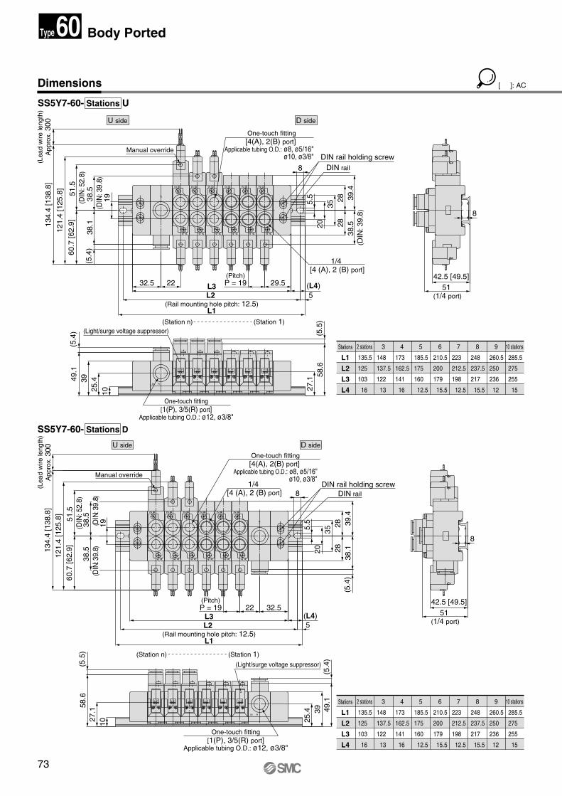
73
Dimensions
D sideU side
D sideU side
SS5Y7-60- Stations U
SS5Y7-60- Stations D
Stations
L1
L2
L3
L4
2 stations
135.5
125
103
16
3
148
137.5
122
13
4
173
162.5
141
16
5
185.5
175
160
12.5
6
210.5
200
179
15.5
7
223
212.5
198
12.5
8
248
237.5
217
15.5
9
260.5
250
236
12
10 stations
285.5
275
255
15
Stations
L1
L2
L3
L4
2 stations
135.5
125
103
16
3
148
137.5
122
13
4
173
162.5
141
16
5
185.5
175
160
12.5
6
210.5
200
179
15.5
7
223
212.5
198
12.5
8
248
237.5
217
15.5
9
260.5
250
236
12
10 stations
285.5
275
255
15
22
(5.5
)
(5.5
)
One-touch fitting[1(P), 3/5(R) port]
Applicable tubing O.D.: ø12, ø3/8"
DIN rail holding screwDIN rail
1/4 [4 (A), 2 (B) port]
Manual override
(Station 1)(Station n)
One-touch fitting[4(A), 2(B) port]
Applicable tubing O.D.: ø8, ø5/16" ø10, ø3/8"
(Light/surge voltage suppressor)
121.
4 [1
25.8
]13
4.4
[138
.8]
60.7
[62.
9]
38.5
(D
IN: 3
9.8)
38
.5
(DIN
: 39.
8)
51.5
(D
IN: 5
2.8)
27.1
42.5 [49.5]32.522
(Pitch)P = 19
(5.4
)38
.139
.4
(5.4
)49
.139
25.4
58.6
8
51 (1/4 port)
L1
5L2 (Rail mounting hole pitch: 12.5)
(L4)L3
8
2828
35
19
(Lea
d w
ire le
ngth
)A
ppro
x. 3
0013
4.4
[138
.8]
121.
4 [1
25.8
]
60.7
[62.
9]
(5.4
)38
.1
1938.5
(D
IN: 3
9.8)
51.5
(D
IN: 5
2.8)
38.5
(D
IN: 3
9.8)
27.1
32.5
58.6
(5.4
)49
.139
25.4
42.5 [49.5]
8
51 (1/4 port)
29.5(Pitch)P = 19
L1
5L2 (Rail mounting hole pitch: 12.5)
(L4)L3
8
39.4
2828
355.5
One-touch fitting[1(P), 3/5(R) port]
Applicable tubing O.D.: ø12, ø3/8"
DIN rail holding screwDIN rail
1/4 [4 (A), 2 (B) port]
Manual override
(Station 1)(Station n)
One-touch fitting[4(A), 2(B) port]
Applicable tubing O.D.: ø8, ø5/16" ø10, ø3/8"
(Light/surge voltage suppressor)
1P
3/5 R
A4B2
A4B2
A4B2
A4B2
A4B2
A4B2
+-+-+- +- +- +-
3/5 R
+-+-+-+-+-+-
A4B2
A4B2
A4B2
A4B2
A4B2
A4B2
1P
1010
20
(Lea
d w
ire le
ngth
)A
ppro
x. 3
00
5.5
20
Body Ported60Type
[ ]: AC
SY.qxd 03.11.11 8:38 AM Page 73
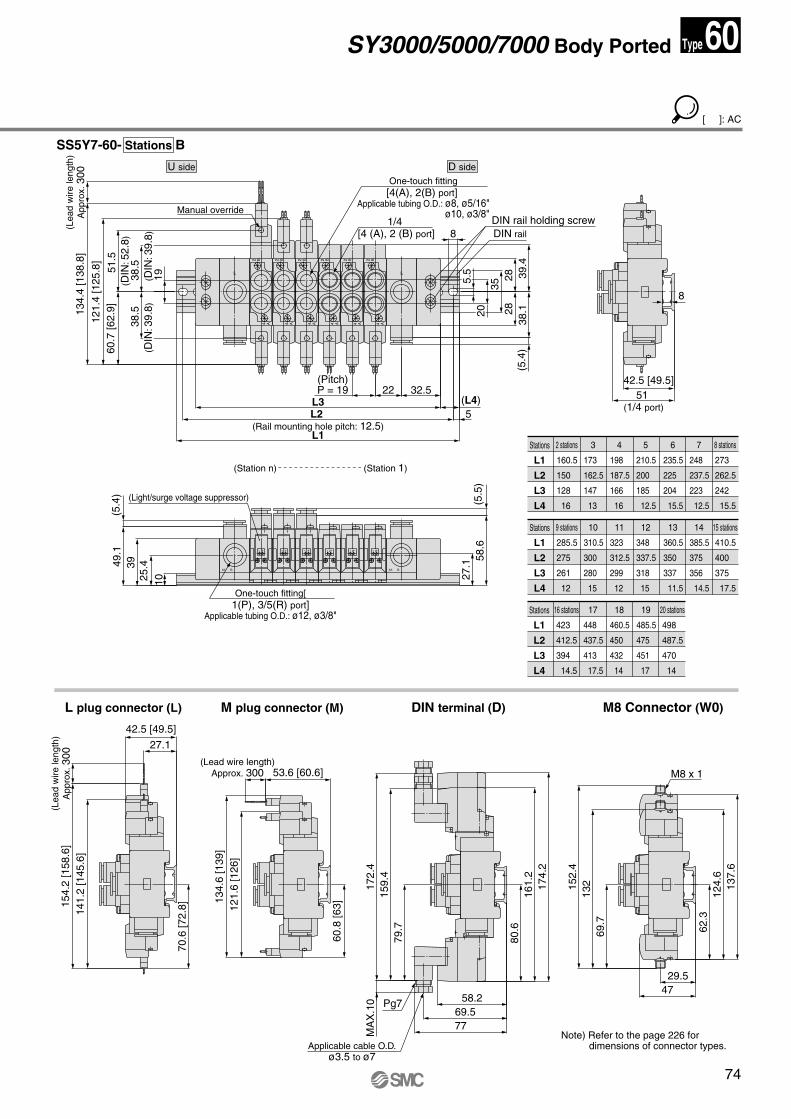
74
D sideU side
Stations
L1
L2
L3
L4
9 stations
285.5
275
261
12
10
310.5
300
280
15
11
323
312.5
299
12
12
348
337.5
318
15
13
360.5
350
337
11.5
14
385.5
375
356
14.5
15 stations
410.5
400
375
17.5
Stations
L1
L2
L3
L4
16 stations
423
412.5
394
14.5
17
448
437.5
413
17.5
19
485.5
475
451
17
20 stations
498
487.5
470
14
18
460.5
450
432
14
Stations
L1
L2
L3
L4
2 stations
160.5
150
128
16
3
173
162.5
147
13
4
198
187.5
166
16
5
210.5
200
185
12.5
6
235.5
225
204
15.5
7
248
237.5
223
12.5
8 stations
273
262.5
242
15.5
SS5Y7-60- Stations B
L plug connector (L) M plug connector (M) DIN terminal (D) M8 Connector (W0)
42.5 [49.5]
8
51 (1/4 port)
(5.5
)
121.
6 [1
26]
134.
6 [1
39]
154.
2 [1
58.6
]14
1.2
[145
.6]
42.5 [49.5]
27.1
60.8
[63]
70.6
[72.
8]
53.6 [60.6](Lead wire length)
Approx. 300
(Lea
d w
ire le
ngth
)A
ppro
x. 3
0013
4.4
[138
.8]
121.
4 [1
25.8
]60
.7 [6
2.9]
19
38.5
(D
IN: 3
9.8)
38
.5
(D
IN: 3
9.8)
51.5
(D
IN: 5
2.8)
27.1
58.6
(Pitch)P = 19 22 32.5
(5.4
)38
.1
49.1
3925
.4
L1
5L2 (Rail mounting hole pitch: 12.5)
(L4)L3
8
39.4
2828
35
(5.4
)
One-touch fitting[1(P), 3/5(R) port]
Applicable tubing O.D.: ø12, ø3/8"
DIN rail holding screwDIN rail
1/4 [4 (A), 2 (B) port]
Manual override
(Station 1)(Station n)
One-touch fitting[4(A), 2(B) port]
Applicable tubing O.D.: ø8, ø5/16" ø10, ø3/8"
(Light/surge voltage suppressor)
1P
3/5 R
A4B2
A4B2
A4B2
+- +- +-
1P
3/5 R
+- +- +-
A4B2
A4B2
A4B2
10
205.
5
(Lea
d w
ire le
ngth
)A
ppro
x. 3
00
7769.5
58.2
M8 x 1
MA
X.1
017
2.4
159.
479
.7
174.
216
1.2
152.
413
269
.7
4729.5
137.
612
4.6
62.3
Applicable cable O.D.ø3.5 to ø7
Pg7
80.6
60Type
[ ]: AC
Note) Refer to the page 226 for dimensions of connector types.
SY3000/5000/7000 Body Ported
SY.qxd 03.11.11 8:38 AM Page 74
75
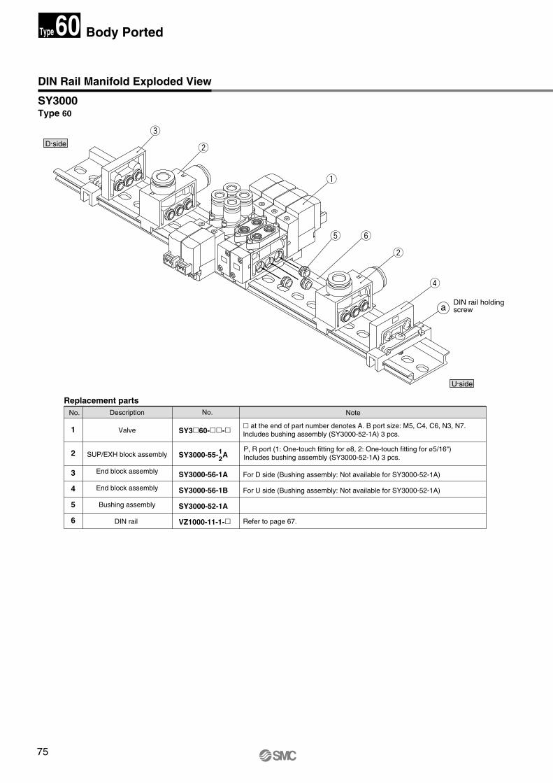
DIN Rail Manifold Exploded View
SY3000 Type 60
Replacement parts
1
2
3
4
5
6
Valve
SUP/EXH block assembly
End block assembly
End block assembly
Bushing assembly
DIN rail
No. Note
� at the end of part number denotes A. B port size: M5, C4, C6, N3, N7.Includes bushing assembly (SY3000-52-1A) 3 pcs.
DescriptionNo.
U side
D side
SY3�60-��-�
SY3000-55- A
SY3000-56-1A
SY3000-56-1B
SY3000-52-1A
VZ1000-11-1-�
For D side (Bushing assembly: Not available for SY3000-52-1A)
For U side (Bushing assembly: Not available for SY3000-52-1A)
Refer to page 67.
P, R port (1: One-touch fitting for ø8, 2: One-touch fitting for ø5/16")Includes bushing assembly (SY3000-52-1A) 3 pcs.
12
a
e
w
q
t y
w
r
P
R
P
R
DIN rail holding screw
Body Ported60Type
SY.qxd 03.11.11 8:38 AM Page 75
76
U side
D side
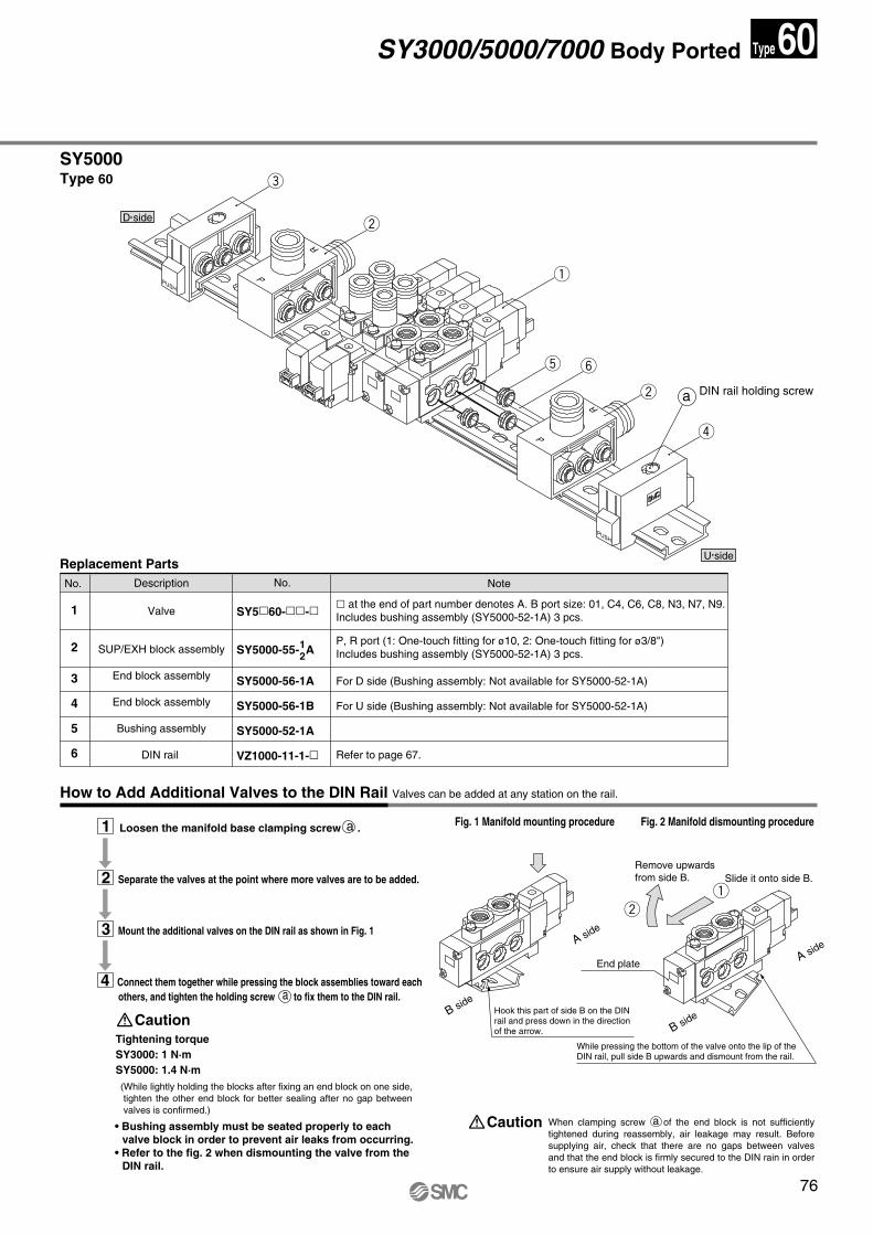
SY5000 Type 60
How to Add Additional Valves to the DIN Rail Valves can be added at any station on the rail.
1 Loosen the manifold base clamping screw a .
2 Separate the valves at the point where more valves are to be added.
3 Mount the additional valves on the DIN rail as shown in Fig. 1
Fig. 1 Manifold mounting procedure Fig. 2 Manifold dismounting procedure
When clamping screw a of the end block is not sufficiently tightened during reassembly, air leakage may result. Before supplying air, check that there are no gaps between valves and that the end block is firmly secured to the DIN rain in order to ensure air supply without leakage.
Caution
Tightening torque SY3000: 1 N·m SY5000: 1.4 N·m
Caution
(While lightly holding the blocks after fixing an end block on one side, tighten the other end block for better sealing after no gap between valves is confirmed.)
Replacement Parts
1
2
3
4
5
6
Valve
SUP/EXH block assembly
End block assembly
End block assembly
Bushing assembly
DIN rail
No. Note
� at the end of part number denotes A. B port size: 01, C4, C6, C8, N3, N7, N9.Includes bushing assembly (SY5000-52-1A) 3 pcs.
DescriptionNo.
SY5�60-��-�
SY5000-55- A
SY5000-56-1A
SY5000-56-1B
SY5000-52-1A
VZ1000-11-1-�
For D side (Bushing assembly: Not available for SY5000-52-1A)
For U side (Bushing assembly: Not available for SY5000-52-1A)
Refer to page 67.
P, R port (1: One-touch fitting for ø10, 2: One-touch fitting for ø3/8")Includes bushing assembly (SY5000-52-1A) 3 pcs.
12
DIN rail holding screwa
P
R
P
R
PUSH
PUSH
Slide it onto side B.
End plate
B side
A sideA side
B side
e
w
q
t y
w
r
qw
4 Connect them together while pressing the block assemblies toward each others, and tighten the holding screw a to fix them to the DIN rail.
Hook this part of side B on the DIN rail and press down in the direction of the arrow.
• Bushing assembly must be seated properly to each valve block in order to prevent air leaks from occurring.
• Refer to the fig. 2 when dismounting the valve from the DIN rail.
Remove upwards from side B.
While pressing the bottom of the valve onto the lip of the DIN rail, pull side B upwards and dismount from the rail.
SY3000/5000/7000 Body Ported 60Type
SY.qxd 03.11.11 8:38 AM Page 76
77
U side
D side
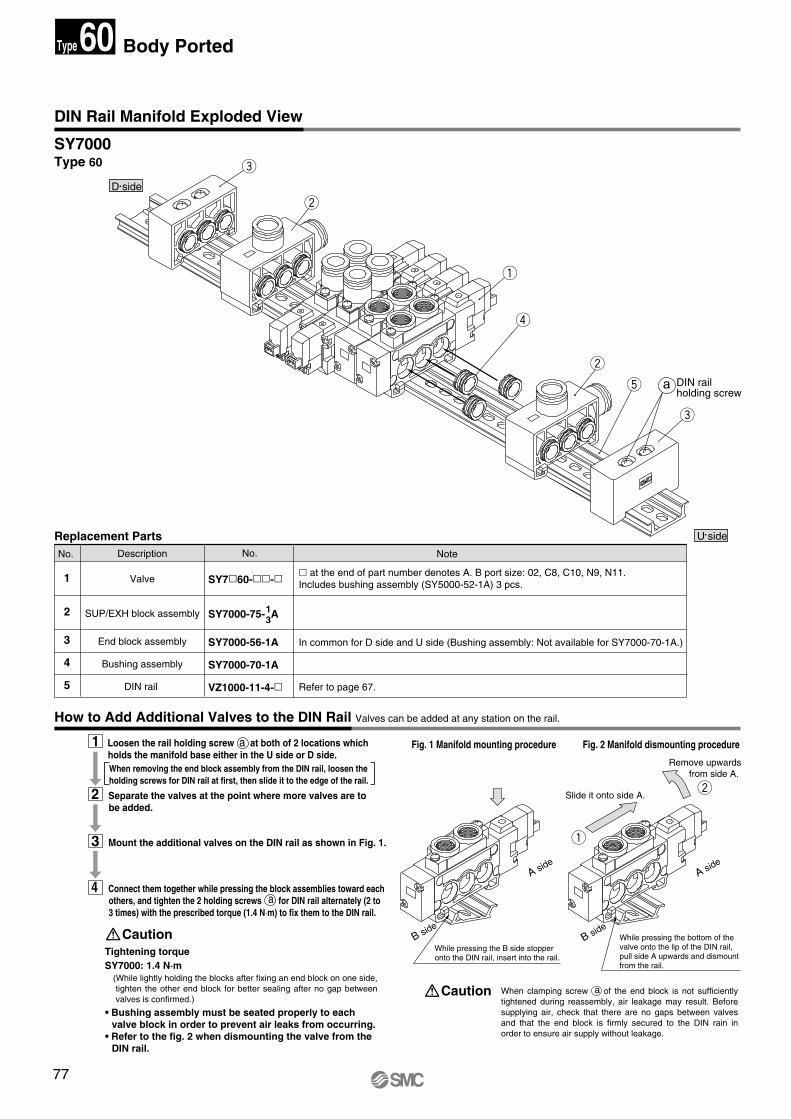
SY7000 Type 60
How to Add Additional Valves to the DIN Rail Valves can be added at any station on the rail.
Fig. 1 Manifold mounting procedure Fig. 2 Manifold dismounting procedure
When clamping screw a of the end block is not sufficiently tightened during reassembly, air leakage may result. Before supplying air, check that there are no gaps between valves and that the end block is firmly secured to the DIN rain in order to ensure air supply without leakage.
Caution
Tightening torque SY7000: 1.4 N·m
Caution
(While lightly holding the blocks after fixing an end block on one side, tighten the other end block for better sealing after no gap between valves is confirmed.)
DIN Rail Manifold Exploded View
Replacement Parts
1
2
3
4
5
Valve
SUP/EXH block assembly
End block assembly
Bushing assembly
DIN rail
No. Note
� at the end of part number denotes A. B port size: 02, C8, C10, N9, N11. Includes bushing assembly (SY5000-52-1A) 3 pcs.
DescriptionNo.
SY7�60-��-�
SY7000-75- A
SY7000-56-1A
SY7000-70-1A
VZ1000-11-4-�
In common for D side and U side (Bushing assembly: Not available for SY7000-70-1A.)
Refer to page 67.
13
a
A side
B side
A side
B side
e
w
q
r
w
q
w
t
e
DIN rail holding screw
1 Loosen the rail holding screw a at both of 2 locations which holds the manifold base either in the U side or D side.
2 Separate the valves at the point where more valves are to be added.
3 Mount the additional valves on the DIN rail as shown in Fig. 1.
4 Connect them together while pressing the block assemblies toward each others, and tighten the 2 holding screws a for DIN rail alternately (2 to 3 times) with the prescribed torque (1.4 N·m) to fix them to the DIN rail.
When removing the end block assembly from the DIN rail, loosen the holding screws for DIN rail at first, then slide it to the edge of the rail.
• Bushing assembly must be seated properly to each valve block in order to prevent air leaks from occurring.
• Refer to the fig. 2 when dismounting the valve from the DIN rail.
While pressing the B side stopper onto the DIN rail, insert into the rail.
Body Ported60Type
Slide it onto side A.
Remove upwards from side A.
While pressing the bottom of the valve onto the lip of the DIN rail, pull side A upwards and dismount from the rail.
SY.qxd 03.11.11 8:38 AM Page 77

78
SY.qxd 03.11.11 8:38 AM Page 78