Embed Size (px)
Citation preview
Synthetic Aperture Radar (SAR)
Team 5: Andy Myrick Steve Hughey Andrew Renton Nur Syuhada Zakaria Sponsor: MIT Lincoln Laboratory Facilitator: Dr. H. Radha

Outline Introduction & Background
How to do it? Antenna Aperture
Phased Arrays
How does it work? Algorithm
Principle
Applications & Alternatives
Summary

Synthetic Aperture Radar
Mostly airborne or space-borne, side-looking radar system
Utilizes the path traversed by the platform [flight path]
Simulate a large antenna or aperture electronically
Generates high-resolution remote sensing imagery
http://www.radartutorial.eu/20.airborne/ab07.en.html Radar Handbook, Skolnik, M.I. 2008
History of SAR Carl A. Wiley, working at Goodyear Aircraft in
1951 invented SAR during research into ICBM guidance systems.
A few months later, University of Illinois and University of Michigan (UM) researchers independently developed SAR.
First SAR imagery produced by UM in 1957. SAR research nearly canceled that year because
the quality and resolution of the images weren’t very impressive.
In 1957, 50 foot resolution was the goal. Today, sub-millimeter resolution is being shown in numerous laboratories.

Image of Haiti after 2010 earthquake taken by ASTER satellite with 50-foot resolution.
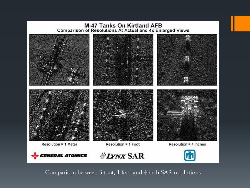
Comparison between 3 foot, 1 foot and 4 inch SAR resolutions

Magellan Mission to Venus Launched – May 4th 1989, Arrived – Aug 10th 1990
To map the surface of Venus using SAR
http://nssdc.gsfc.nasa.gov/planetary/magellan.html http://www.youtube.com/watch?v=79bX6aYe74I

Antenna’s “Footprint”
The beam sent out by the antenna illuminates an area on the targeted object
Known as the antenna’s “footprint”
The recorded signal strength depends on the energy back scattered from the target inside this footprint
http://www.crisp.nus.edu.sg/~research/tutorial/mw.htm
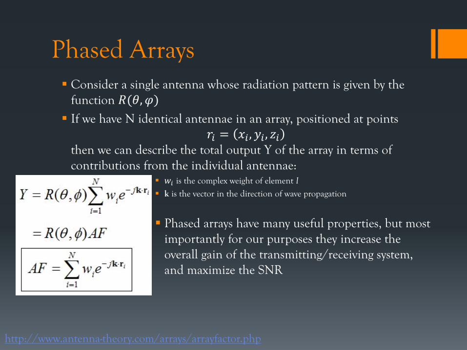
Phased Arrays Consider a single antenna whose radiation pattern is given by the
function 𝑅(𝜃, 𝜑)
If we have N identical antennae in an array, positioned at points 𝑟𝑖 = 𝑥𝑖 , 𝑦𝑖 , 𝑧𝑖
then we can describe the total output Y of the array in terms of contributions from the individual antennae:
𝑤𝑖 is the complex weight of element I
k is the vector in the direction of wave propagation
Phased arrays have many useful properties, but most importantly for our purposes they increase the overall gain of the transmitting/receiving system, and maximize the SNR
http://www.antenna-theory.com/arrays/arrayfactor.php
SAR analogy with phased arrays
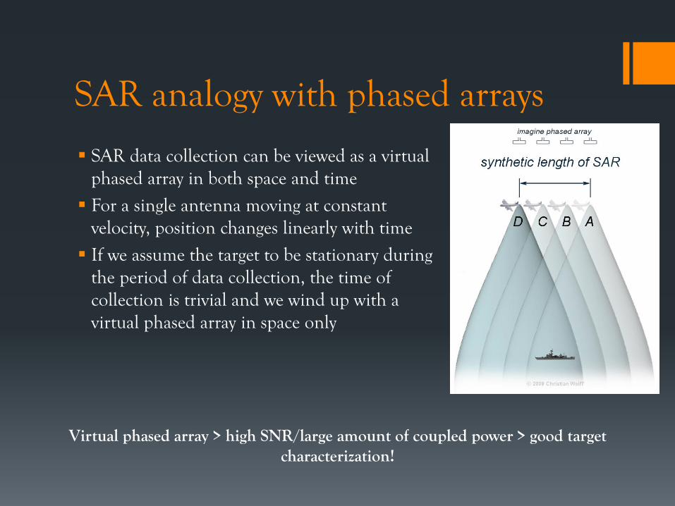
SAR data collection can be viewed as a virtual phased array in both space and time
For a single antenna moving at constant velocity, position changes linearly with time
If we assume the target to be stationary during the period of data collection, the time of collection is trivial and we wind up with a virtual phased array in space only
Virtual phased array > high SNR/large amount of coupled power > good target characterization!

Antenna Apertures & Arrays
More energy collected
More gain compared to isotropic
More SNR
Narrower half-power beam width
Greater angular resolution
More elements
http://ocw.mit.edu/courses/
Larger Aperture Longer Array
Uses one antenna in time-multiplex to operate similar to phased array

General SAR System
Pulse generation creates pulses with a bandwidth according to the range resolution
Sender amplifies the pulses and transfer it to the antenna via circulator Receivers amplifies the output signal of antenna and applies a band pass filter After the demodulation and A/D conversion, the SAR processor calculates the
SAR image Radar control unit arranges the operation sequence particularly the time
schedule
http://ftp.rta.nato.int/public//PubFullText/RTO/EN/RTO-EN-SET-086///EN-SET-086-03.pdf
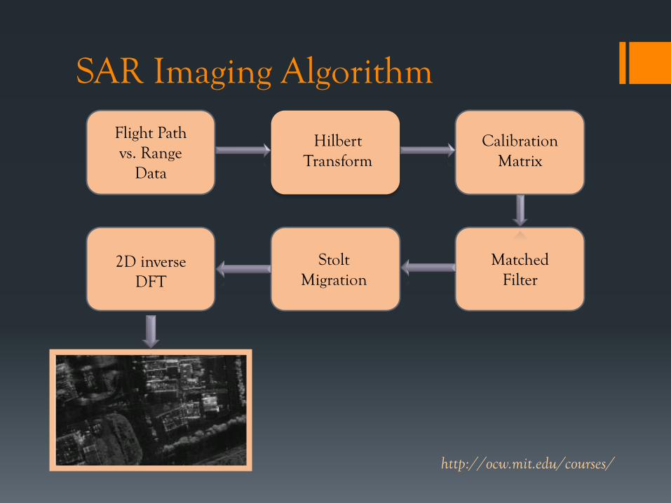
SAR Imaging Algorithm
Flight Path vs. Range
Data
Hilbert Transform
Calibration Matrix
Matched Filter
Stolt Migration
2D inverse DFT
http://ocw.mit.edu/courses/
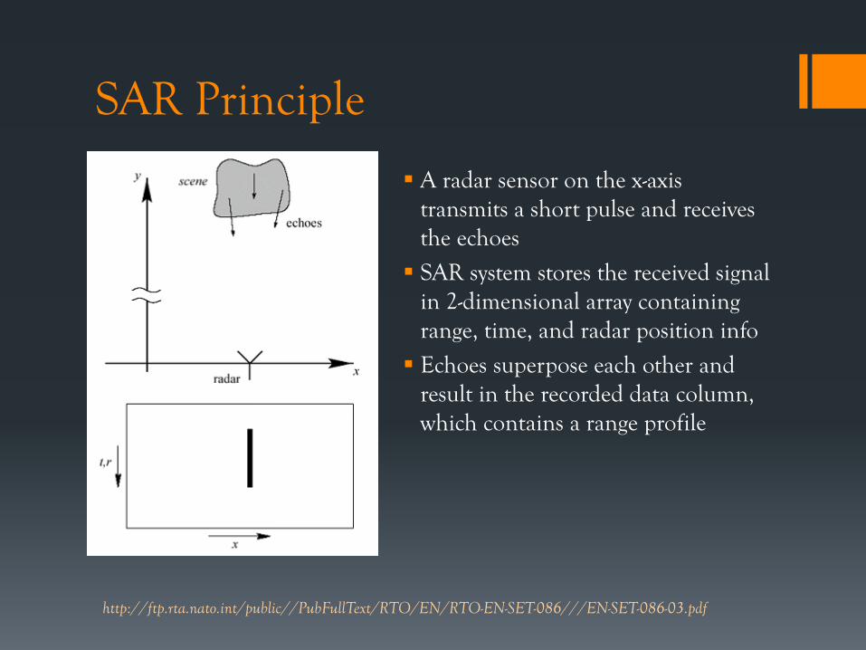
SAR Principle
A radar sensor on the x-axis transmits a short pulse and receives the echoes
SAR system stores the received signal in 2-dimensional array containing range, time, and radar position info
Echoes superpose each other and result in the recorded data column, which contains a range profile
http://ftp.rta.nato.int/public//PubFullText/RTO/EN/RTO-EN-SET-086///EN-SET-086-03.pdf

SAR Principle 3 point targets are given at different
positions The antenna moves in steps along
the x-direction taking data samples A hyperbolic range history in the
data results for each reflector, indicated by the curves
Points will be generated in a second data array at the positions of the hyperbola vertex
The signal intensity of the individual echoes, resulting from the reflectivity of the scene, controls the brightness of the points in the second data array, an image of the scene results
*point target – small object with reflectivity assumed to be at one discrete point http://ftp.rta.nato.int/public//PubFullText/RTO/EN/RTO-EN-SET-086///EN-SET-086-03.pdf
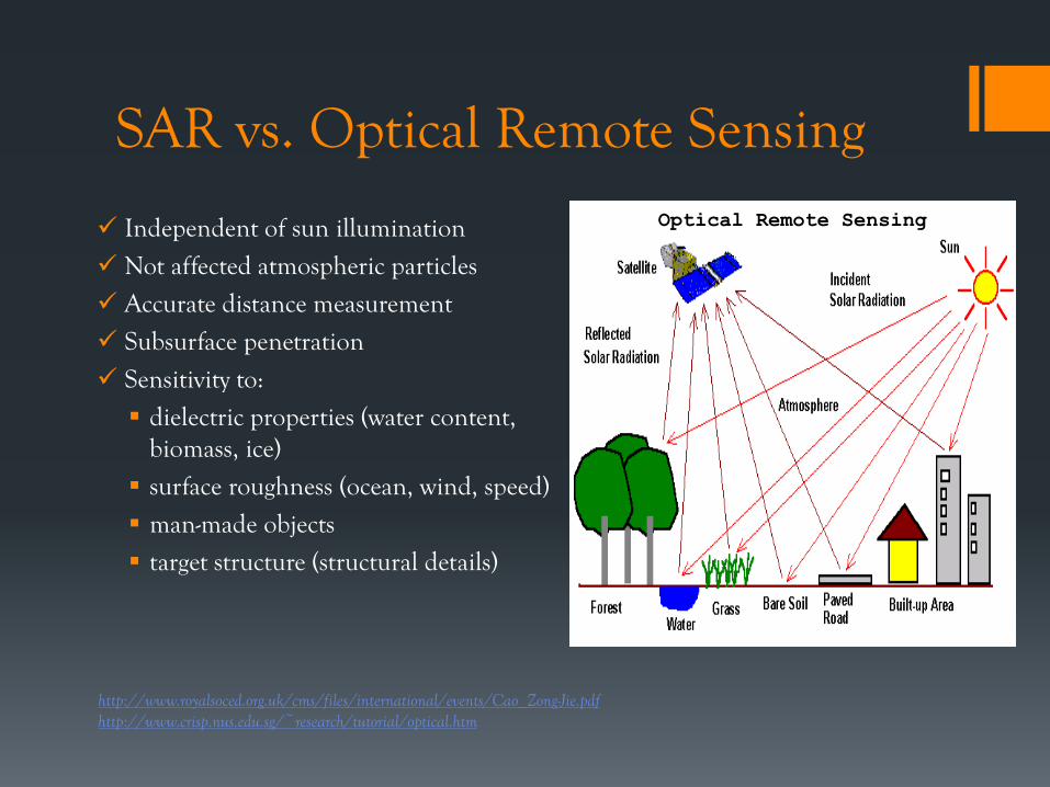
SAR vs. Optical Remote Sensing
Independent of sun illumination
Not affected atmospheric particles
Accurate distance measurement
Subsurface penetration
Sensitivity to:
dielectric properties (water content, biomass, ice)
surface roughness (ocean, wind, speed)
man-made objects
target structure (structural details)
http://www.royalsoced.org.uk/cms/files/international/events/Cao_Zong-Jie.pdf http://www.crisp.nus.edu.sg/~research/tutorial/optical.htm
Optical Remote Sensing

Applications of SAR
Military Surveillance and Targeting
Aerial SAR image of M-47 tanks
http://www.sandia.gov/RADAR/sarapps.html Radar Handbook, Skolnik, M.I. 2008
Optical image of M-47 tanks
3D Imaging
Use 2 antennas on same air craft or make 2 passes offset in space
Low-frequency (10 MHz – 1 GHz) SAR can penetrate the ground and optically opaque materials

Other Applications
http://www.royalsoced.org.uk/cms/files/international/events/Cao_Zong-Jie.pdf
Agricultural Survey
Environment Protection Urban Construction
Natural Disaster Monitoring
Oil spill segmentation result
Soil moisture of an agricultural filed
Road network extraction, Guan Xian, China
Flood monitoring, Targus river, Portugal

Backyard SAR by MITLL
Aircraft Image on the Styrofoam Table
http://ocw.mit.edu/courses/
Type : Rail

Summary SAR is mostly airborne or space borne
Used to capture the image of earth’s surface
Works similar to phased antennas
How it works? Algorithm
Principle
Applications & Alternatives
QUESTIONS?