Embed Size (px)
Citation preview
1667
†To whom correspondence should be addressed.
E-mail: [email protected]
Korean J. Chem. Eng., 30(9), 1667-1680 (2013)DOI: 10.1007/s11814-013-0140-6
REVIEW PAPER
Synthesis of metal-organic frameworks: A mini review
Yu-Ri Lee, Jun Kim, and Wha-Seung Ahn†
Department of Chemistry and Chemical Engineering, Inha University, Incheon 402-751, Korea(Received 10 May 2013 • accepted 30 July 2013)
Abstract−Metal organic frameworks (MOFs) are porous crystalline materials of one-, two-, or three-dimensional
networks constructed from metal ions/clusters and multidentate organic linkers via coordination bonding, which are
emerging as an important group of materials for energy storage, CO2 adsorption, alkane/alkene separation, and catalysis.
To introduce newcomers in chemical engineering discipline to the rapidly expanding MOF research works, this review
presents a brief introduction to the currently available MOFs synthesis methods. Starting from the conventional solvother-
mal/hydrothermal synthesis, microwave-assisted, sonochemical, electrochemical, mechanochemical, ionothermal, dry-
gel conversion, and microfluidic synthesis methods will be presented. Examples will be limited to those representa-
tive MOF structures that can be synthesized using common organic ligands of 1,4-benzenedicarboxylic acid (and its
functionalized forms) and 1,3,5-benzenetricarboxylic acid, in conjunction with metal nodes of Zn2+, Cu2+, Cr3+, Al3+,
Fe3+ and Zr4+. Synthesis of widely-investigated zeolitic imidazolate framework (ZIF) structure, ZIF-8 is also included.
Key words: Metal Organic Frameworks (MOFs), Zeolitic Imidazolate Frameworks (ZIFs), Solvothermal/Hydrothermal
Synthesis, Microwave, Sonochemistry, Electrochemical Synthesis, Mechanochemical Synthesis
INTRODUCTION
Metal organic frameworks (MOFs) are a class of crystalline or-
ganic-inorganic hybrid compounds formed by coordination of metal
clusters or ions with organic linkers, in which bivalent or trivalent
aromatic carboxylic acids or N-containing aromatics are commonly
used to form frameworks with zinc, copper, chromium, aluminum,
zirconium, and other elements [1-9]. Since MOFs have high sur-
face areas and high pore volumes in uniformly sized pores as well
as high metal content, they have emerged as interesting materials
for various applications in energy storage [10,11], CO2 adsorption
[12,13], hydrocarbon adsorption/separation [14-16], catalysis [17-
19], sensor [20], magnetism [21], drug delivery [22], luminescence
[23,24], and others. Recent extensive review articles on MOFs have
dealt with synthesis, characterization, surface modification, and appli-
cations [3-5,19,25,26]. Our aim is to provide more specific and engi-
neering-orientated information on the synthesis of MOF materials
expected for use as adsorbents and catalysts in industry. For more
broad understanding on the topic, the review article by Stock and
Biswas [26] is strongly recommended.
Thus far, MOFs have been generally prepared via hydrothermal
or solvothermal synthesis routines by electrical heating in small scales,
which take reaction time from several hours to days. Efforts were
primarily given to preparing high quality single crystals adequate
for structural analysis in dilute liquid phase conditions. Alternative
synthesis methods were attempted afterward in an effort to shorten
the synthesis time and to produce smaller and uniform crystals, such
as microwave-assisted [16,27,28], sonochemical [29-31], electro-
chemical [32,33], and mechanochemical methods [34,35]. Limited
synthesis scale-up for industrial applications was also conducted
[36,37]; sometimes, detailed investigations on the optimization of
MOF synthesis conditions in these studies were carried out in order
to obtain high yields of solid products for industrial applications.
In this mini review, we examine MOF synthesis methods reported
in the open literatures. Attention is only given to the preparation of
the MOF structures described in Scheme1, which are prepared using
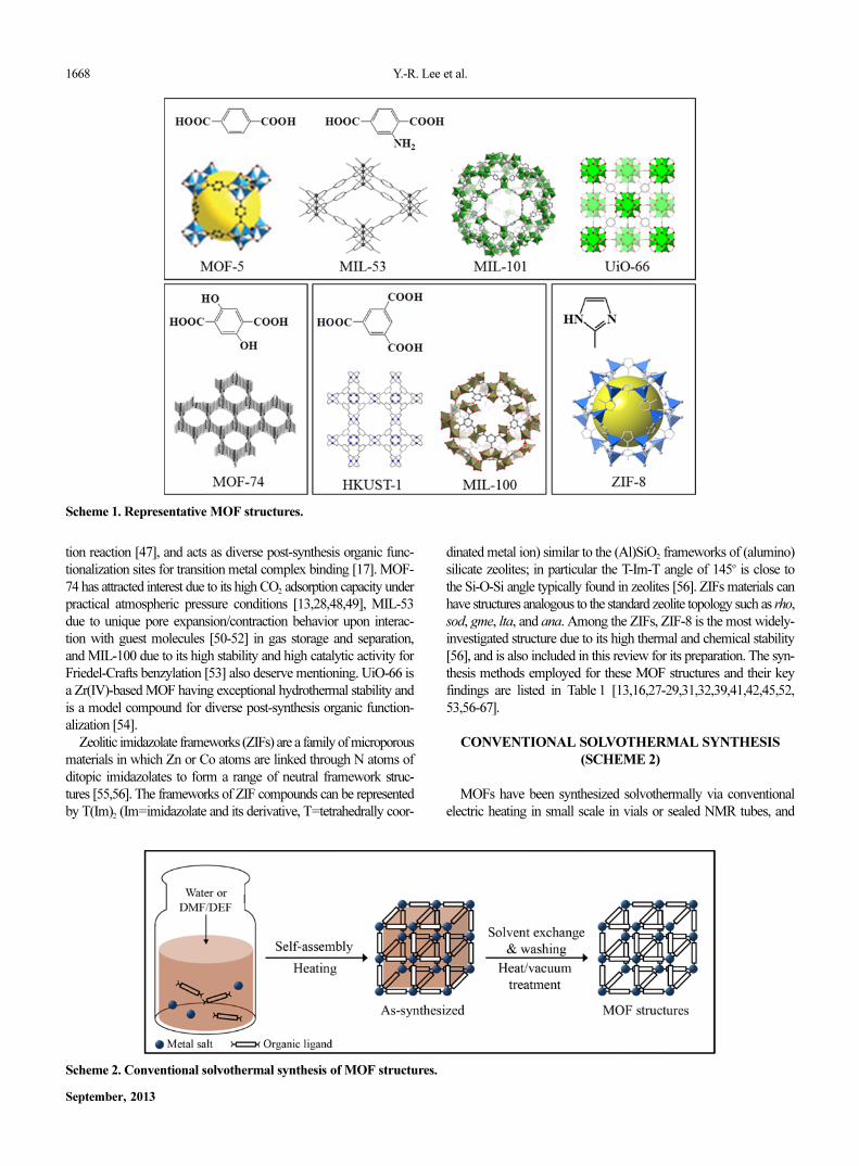
an organic ligand such as H2BDC (1,4-benzenedicarboxylic acid)
and its functionalized form (H2BDC-NH2; 2-amino-1,4-benzenedi-
carboxylic acid, H2BDC-(OH)2; 2,5-dihydroxy-1,4-benzenedicar-
boxylic acid), or H3BTC (1,3,5-benzenetricarboxylic acid). MOF-5
reported in 1999 in Nature by Yagi et al. had attracted huge atten-
tion due to its robust open framework structure supporting perma-
nent porosity and simple design strategy for pore size control [38],
which ignited active investigations toward MOF applications to gas
storage [39] and heterogeneous catalysis [40]. However, after its weak
hydrothermal stability was revealed, attention shifted to HKUST-1
[41] because of its good stability against moisture, excellent ther-
mal stability, and relatively easy synthesis. Currently, MIL-101 seems
to be the most frequently adopted material for catalysis and adsorp-
tion. MIL-101(Cr3O(F/OH)(H2O)2[C6H4(CO2)2]3) by Ferey et al. is a
robust MOF with high surface area, typically prepared hydrother-
mally using a chromium salt and H2BDC in an autoclave under auto-
genous pressure conditions [42]. MIL-101 is unique in that it exhibits
exceptional stability against moisture and other chemicals, and is
composed of coordinatively unsaturated Cr-sites in high concentra-
tion available for catalysis and adsorption [43-45]. MIL-101 with a
BET (Brunauer, Emmett, and Teller) surface area greater than 4,000
m2/g is, however, very difficult to obtain because the impurities pro-
duced by the unreacted H2BDC or recrystallized H2BDC are present
both outside and within the pores of MIL-101 [46]. NH2-function-
alization in MOF-5 produces IRMOF-3, which imparts basicity to
MOF-5 framework and produces an enhancement in CO2 capture
capacity [39], provides catalytic sites for Knoevenagel condensa-
1668 Y.-R. Lee et al.
September, 2013
tion reaction [47], and acts as diverse post-synthesis organic func-
tionalization sites for transition metal complex binding [17]. MOF-
74 has attracted interest due to its high CO2 adsorption capacity under
practical atmospheric pressure conditions [13,28,48,49], MIL-53
due to unique pore expansion/contraction behavior upon interac-
tion with guest molecules [50-52] in gas storage and separation,
and MIL-100 due to its high stability and high catalytic activity for
Friedel-Crafts benzylation [53] also deserve mentioning. UiO-66 is
a Zr(IV)-based MOF having exceptional hydrothermal stability and
is a model compound for diverse post-synthesis organic function-
alization [54].
Zeolitic imidazolate frameworks (ZIFs) are a family of microporous
materials in which Zn or Co atoms are linked through N atoms of
ditopic imidazolates to form a range of neutral framework struc-
tures [55,56]. The frameworks of ZIF compounds can be represented
by T(Im)2 (Im=imidazolate and its derivative, T=tetrahedrally coor-
dinated metal ion) similar to the (Al)SiO2 frameworks of (alumino)
silicate zeolites; in particular the T-Im-T angle of 145o is close to
the Si-O-Si angle typically found in zeolites [56]. ZIFs materials can
have structures analogous to the standard zeolite topology such as rho,
sod, gme, lta, and ana. Among the ZIFs, ZIF-8 is the most widely-
investigated structure due to its high thermal and chemical stability
[56], and is also included in this review for its preparation. The syn-
thesis methods employed for these MOF structures and their key
findings are listed in Table 1 [13,16,27-29,31,32,39,41,42,45,52,
53,56-67].
CONVENTIONAL SOLVOTHERMAL SYNTHESIS
(SCHEME 2)
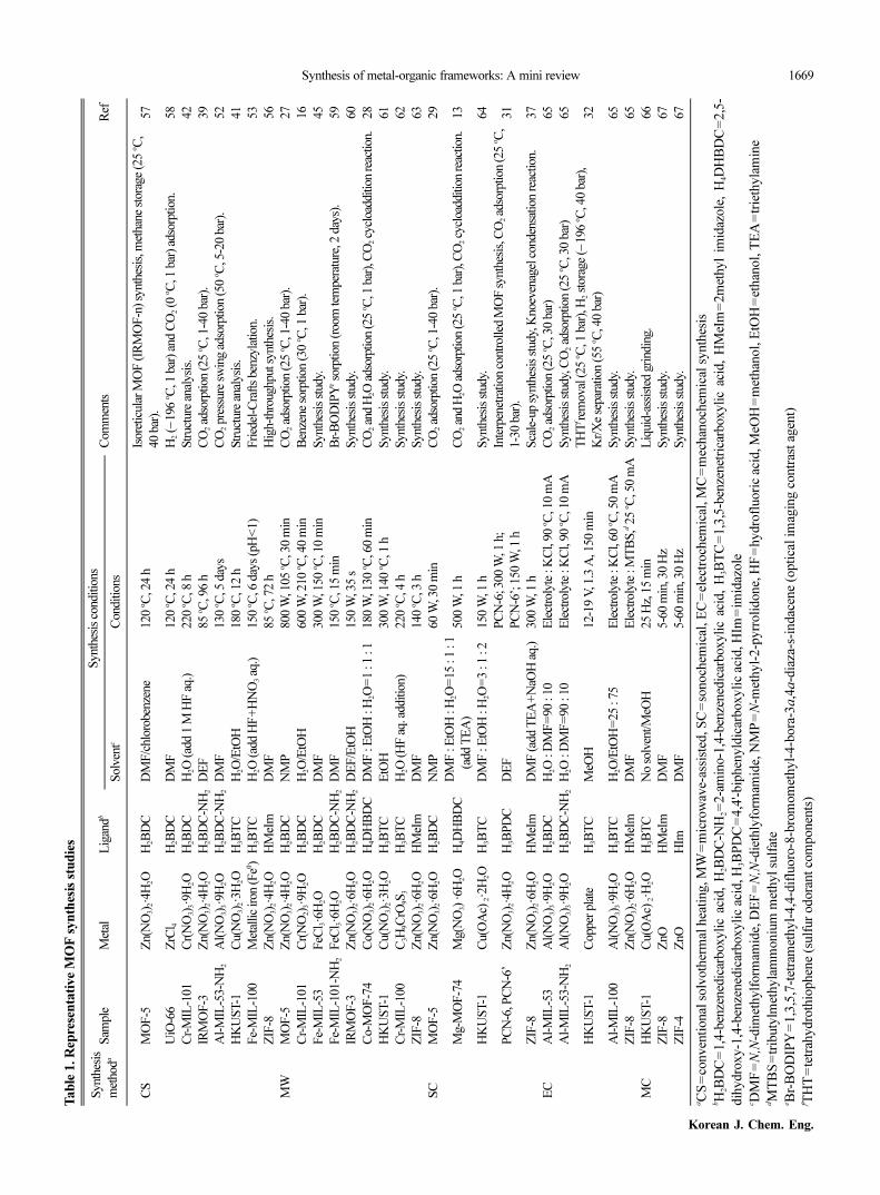
MOFs have been synthesized solvothermally via conventional
electric heating in small scale in vials or sealed NMR tubes, and
Scheme 1. Representative MOF structures.
Scheme 2. Conventional solvothermal synthesis of MOF structures.
Synthesis of metal-organic frameworks: A mini review 1669
Korean J. Chem. Eng.
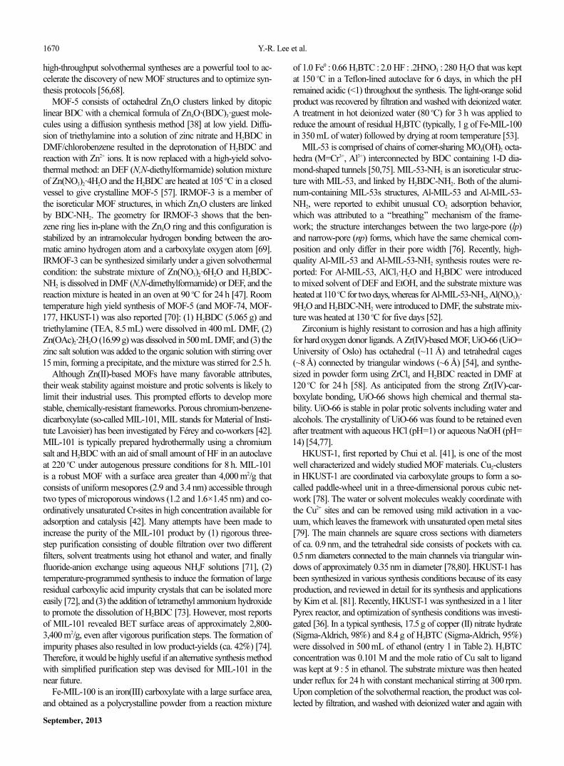
Tab
le1.R
ep
resen
tati
ve M
OF
syn
thesis
stu
die
s
Synth
esis
met
hoda
Sam
ple
Met
alL
igan
db
Synth
esis
conditio
ns
Com
men
tsR
efS
olv
entc
Conditio
ns
CS
MO
F-5
Zn(N
O3) 2
·4H
2O
H2B
DC
DM
F/c
hlo
roben
zene
120
oC
, 24
hIs
ore
ticu
lar M
OF
(IR
MO
F-n
) sy
nth
esis
, met
han
e st
ora
ge
(25
oC
,
40
bar
).57
UiO
-66
ZrC
l 4H
2B
DC
DM
F120
oC
, 24
hH
2 (−
196
oC
, 1bar
) an
d C
O2 (0
oC
, 1bar
) ad
sorp
tion.
58
Cr-
MIL
-101
Cr(
NO
3) 3
·9H
2O
H2B
DC
H2O
(ad
d 1
M H
F a
q.)
220
oC
, 8h
Str
uct
ure
anal
ysi
s.42
IRM
OF
-3Z
n(N
O3) 2
·4H
2O
H2B
DC
-NH
2D
EF
85
oC
, 96
hC
O2 a
dso
rption (25
oC
, 1-4
0bar
).39
Al-
MIL
-53-N
H2
Al(
NO
3) 3
·9H
2O
H2B
DC
-NH
2D
MF
130
oC
, 5 d
ays
CO
2 p
ress
ure
sw
ing a
dso
rption (50
oC
, 5-2
0bar
).52
HK
US
T-1
Cu(N
O3) 2
·3H
2O
H3B
TC
H2O
/EtO
H180
oC
, 12
hStr
uct
ure
anal
ysi
s.41
Fe-
MIL
-100
Met
allic
iron (F
e0)
H3B
TC
H2O
(ad
d H
F+
HN
O3 a
q.)
150
oC
, 6 d
ays
(pH
<1)
Fri
edel
-Cra
fts
ben
zyla
tion.
53
ZIF
-8Z
n(N
O3) 2
·4H
2O
HM
eIm
DM
F85
oC
, 72
hH
igh-t
hro
ughput s
ynth
esis
.56
MW
MO
F-5
Zn(N
O3) 2
·4H
2O
H2B
DC
NM
P800
W, 1
05
oC
, 30
min
CO
2 a
dso
rption (25
oC
, 1-4
0bar
).27
Cr-
MIL
-101
Cr(
NO
2) 3
·9H
2O
H2B
DC
H2O
/EtO
H600
W, 2
10
oC
, 40
min
Ben
zene
sorp
tion (30
oC
, 1bar
).16
Fe-
MIL
-53
FeC
l 3·6
H2O
H2B
DC
DM
F300
W, 1
50
oC
, 10
min
Synth
esis
stu
dy.
45
Fe-
MIL
-101-N
H2
FeC
l 3·6
H2O
H
2B
DC
-NH
2D
MF
150
oC
, 15
min
Br-
BO
DIP
Ye s
orp
tion (ro
om
tem
per
ature
, 2 d
ays)
.59
IRM
OF
-3Z
n(N
O3) 2
·6H
2O
H2B
DC
-NH
2D
EF
/EtO
H150
W, 3
5s
Synth
esis
stu
dy.
60
Co-M
OF
-74
Co(N
O3) 2
·6H
2O
H4D
HB
DC
DM
F:E
tOH
:H2O
=1
:1:1
180
W, 1
30
oC
, 60
min
CO
2 a
nd H
2O
ads
orp
tion
(25
oC
, 1bar
), C
O2 c
ycl
oaddi
tion
rea
ctio
n.28
HK
US
T-1
Cu(N
O3) 2
·3H
2O
H3B
TC
EtO
H300
W, 1
40
oC
, 1h
Synth
esis
stu
dy.
61
Cr-
MIL
-100
C3H
9C
rO9S
3H
3B
TC
H2O
(H
F a
q. a
dditio
n)
220
oC
, 4h
Synth
esis
stu
dy.
62
ZIF
-8Z
n(N
O3) 2
·6H
2O
HM
eIm
DM
F140
oC
, 3h
Synth
esis
stu
dy.
63
SC
MO
F-5
Zn(N
O3) 2
·6H
2O
H2B
DC
NM
P60
W, 3
0m
inC
O2 a
dso
rption (25
oC
, 1-4
0bar
).29
Mg-M
OF
-74
Mg(N
O3)
·6H
2O
H4D
HB
DC
DM
F:E
tOH
:H2O
=15
:1
:1
(add T
EA
)500
W, 1
hC
O2 a
nd H
2O
ads
orp
tion
(25
oC
, 1bar
), C
O2 c
ycl
oaddi
tion
rea
ctio
n.13
HK
US
T-1
Cu(O
Ac)
2·2
H2O
H3B
TC
DM
F:E
tOH
:H2O
=3
:1:2
150
W, 1
hS
ynth
esis
stu
dy.
64
PC
N-6
, PC
N-6
’Z
n(N
O3) 2
·4H
2O
H3B
PD
CD
EF
PC
N-6
; 300
W, 1
h;
PC
N-6
’; 1
50
W, 1
h
Inte
rpen
etra
tion c
ontr
olled
MO
F s
ynth
esis
, CO
2 a
dso
rption (25
oC
,
1-3
0bar
).31
ZIF
-8Z
n(N
O3) 2
·6H
2O
HM
eIm
DM
F (ad
d T
EA
+N
aOH
aq.)
300
W, 1
hS
cale
-up s
ynth
esis
stu
dy,
Knoev
enag
el c
onden
sation rea
ctio
n.
37
EC
Al-
MIL
-53
Al(
NO
3) 3
·9H
2O
H2B
DC
H2O
:DM
F=
90
:10
Ele
ctro
lyte
:K
Cl,
90
oC
, 10
mA
CO
2 a
dso
rption (25
oC
, 30
bar
) 65
Al-
MIL
-53-N
H2
Al(
NO
3) 3
·9H
2O
H2B
DC
-NH
2H
2O
:DM
F=
90
:10
Ele
ctro
lyte
:K
Cl,
90
oC
, 10
mA
Synth
esis
stu
dy,
CO
2 a
dso
rption (25
oC
, 30
bar
) 65
HK
US
T-1
Copper
pla
teH
3B
TC
MeO
H12-1
9V
, 1.3
A, 1
50
min
TH
Tf re
moval
(25
oC
, 1bar
), H
2 s
tora
ge
(−196
oC
, 40
bar
),
Kr/
Xe
separ
atio
n (55 oC
, 40 b
ar)
32
Al-
MIL
-100
Al(
NO
3) 3
·9H
2O
H3B
TC
H2O
/EtO
H=
25
:75
Ele
ctro
lyte
:K
Cl,
60
oC
, 50
mA
Synth
esis
stu
dy.
65
ZIF
-8Z
n(N
O3) 2
·6H
2O
HM
eIm
DM
FE
lect
roly
te:M
TB
S,d 2
5oC
, 50
mA
Synth
esis
stu
dy.
65
MC
HK
US
T-1
Cu(O
Ac)
2·H
2O
H3B
TC
No s
olv
ent/M
eOH
25
Hz,
15
min
Liq
uid
-ass
iste
d g
rindin
g.
66
ZIF
-8Z
nO
HM
eIm
DM
F5-6
0m
in, 3
0H
zS
ynth
esis
stu
dy.
67
ZIF
-4Z
nO
HIm
DM
F5-6
0 m
in, 3
0H
zS
ynth
esis
stu
dy.
67
aC
S=
conven
tional
solv
oth
erm
al h
eati
ng, M
W=
mic
row
ave-
assi
sted
, S
C=
sonoch
emic
al, E
C=
elec
troch
emic
al, M
C=
mec
han
och
emic
al s
ynth
esis
bH
2B
DC
=1,4
-ben
zened
icar
boxyli
c ac
id,
H2B
DC
-NH
2=
2-a
min
o-1
,4-b
enze
ned
icar
boxyli
c ac
id,
H3B
TC
=1,3
,5-b
enze
net
rica
rboxyli
c ac
id,
HM
eIm
=2m
ethyl
imid
azole
, H
4D
HB
DC
=2,5
-
dih
ydro
xy-1
,4-b
enze
ned
icar
boxyli
c ac
id, H
3B
PD
C=
4,4
'-bip
hen
yld
icar
boxyli
c ac
id, H
Im=
imid
azole
c DM
F=N,N
-dim
ethylf
orm
amid
e, D
EF
=N,N
-die
thly
form
amid
e, N
MP
=N
-met
hyl-
2-p
yrr
oli
done,
HF
=hydro
fluori
c ac
id, M
eOH
=m
ethan
ol, E
tOH
=et
han
ol, T
EA
=tr
ieth
yla
min
edM
TB
S=
trib
uty
lmet
hyla
mm
oniu
m m
ethyl su
lfat
ee B
r-B
OD
IPY
=1,3
,5,7
-tet
ram
ethyl-
4,4
-dif
luoro
-8-b
rom
om
ethyl-
4-b
ora
-3a,4a-d
iaza
-s-i
ndac
ene
(opti
cal im
agin
g c
ontr
ast
agen
t)f T
HT
=te
trah
ydro
thio
phen
e (s
ulf
ur
odora
nt co
mponen
ts)
1670 Y.-R. Lee et al.
September, 2013
high-throughput solvothermal syntheses are a powerful tool to ac-celerate the discovery of new MOF structures and to optimize syn-thesis protocols [56,68].
MOF-5 consists of octahedral Zn4O clusters linked by ditopiclinear BDC with a chemical formula of Zn4O·(BDC)3·guest mole-cules using a diffusion synthesis method [38] at low yield. Diffu-sion of triethylamine into a solution of zinc nitrate and H2BDC inDMF/chlorobenzene resulted in the deprotonation of H2BDC andreaction with Zn2+ ions. It is now replaced with a high-yield solvo-thermal method: an DEF (N,N-diethylformamide) solution mixtureof Zn(NO3)2·4H2O and the H2BDC are heated at 105 oC in a closedvessel to give crystalline MOF-5 [57]. IRMOF-3 is a member ofthe isoreticular MOF structures, in which Zn4O clusters are linkedby BDC-NH2. The geometry for IRMOF-3 shows that the ben-zene ring lies in-plane with the Zn4O ring and this configuration isstabilized by an intramolecular hydrogen bonding between the aro-matic amino hydrogen atom and a carboxylate oxygen atom [69].IRMOF-3 can be synthesized similarly under a given solvothermalcondition: the substrate mixture of Zn(NO3)2·6H2O and H2BDC-NH2 is dissolved in DMF (N,N-dimethylformamide) or DEF, and thereaction mixture is heated in an oven at 90 oC for 24 h [47]. Roomtemperature high yield synthesis of MOF-5 (and MOF-74, MOF-177, HKUST-1) was also reported [70]: (1) H2BDC (5.065 g) andtriethylamine (TEA, 8.5 mL) were dissolved in 400 mL DMF, (2)Zn(OAc)2·2H2O (16.99g) was dissolved in 500 mL DMF, and (3) thezinc salt solution was added to the organic solution with stirring over15 min, forming a precipitate, and the mixture was stirred for 2.5 h.
Although Zn(II)-based MOFs have many favorable attributes,their weak stability against moisture and protic solvents is likely tolimit their industrial uses. This prompted efforts to develop morestable, chemically-resistant frameworks. Porous chromium-benzene-dicarboxylate (so-called MIL-101, MIL stands for Material of Insti-tute Lavoisier) has been investigated by Férey and co-workers [42].MIL-101 is typically prepared hydrothermally using a chromiumsalt and H2BDC with an aid of small amount of HF in an autoclaveat 220 oC under autogenous pressure conditions for 8 h. MIL-101is a robust MOF with a surface area greater than 4,000 m2/g thatconsists of uniform mesopores (2.9 and 3.4 nm) accessible throughtwo types of microporous windows (1.2 and 1.6×1.45 nm) and co-ordinatively unsaturated Cr-sites in high concentration available foradsorption and catalysis [42]. Many attempts have been made toincrease the purity of the MIL-101 product by (1) rigorous three-step purification consisting of double filtration over two differentfilters, solvent treatments using hot ethanol and water, and finallyfluoride-anion exchange using aqueous NH4F solutions [71], (2)temperature-programmed synthesis to induce the formation of largeresidual carboxylic acid impurity crystals that can be isolated moreeasily [72], and (3) the addition of tetramethyl ammonium hydroxideto promote the dissolution of H2BDC [73]. However, most reportsof MIL-101 revealed BET surface areas of approximately 2,800-3,400 m2/g, even after vigorous purification steps. The formation ofimpurity phases also resulted in low product-yields (ca. 42%) [74].Therefore, it would be highly useful if an alternative synthesis methodwith simplified purification step was devised for MIL-101 in thenear future.
Fe-MIL-100 is an iron(III) carboxylate with a large surface area,and obtained as a polycrystalline powder from a reaction mixture
of 1.0 Fe0 : 0.66 H3BTC : 2.0 HF : .2HNO3 : 280 H2O that was keptat 150 oC in a Teflon-lined autoclave for 6 days, in which the pHremained acidic (<1) throughout the synthesis. The light-orange solidproduct was recovered by filtration and washed with deionized water.A treatment in hot deionized water (80 oC) for 3 h was applied toreduce the amount of residual H3BTC (typically, 1 g of Fe-MIL-100in 350 mL of water) followed by drying at room temperature [53].
MIL-53 is comprised of chains of corner-sharing MO4(OH)2 octa-hedra (M=Cr3+, Al3+) interconnected by BDC containing 1-D dia-mond-shaped tunnels [50,75]. MIL-53-NH2 is an isoreticular struc-ture with MIL-53, and linked by H2BDC-NH2. Both of the alumi-num-containing MIL-53s structures, Al-MIL-53 and Al-MIL-53-NH2, were reported to exhibit unusual CO2 adsorption behavior,which was attributed to a ‘‘breathing’’ mechanism of the frame-work; the structure interchanges between the two large-pore (lp)and narrow-pore (np) forms, which have the same chemical com-position and only differ in their pore width [76]. Recently, high-quality Al-MIL-53 and Al-MIL-53-NH2 synthesis routes were re-ported: For Al-MIL-53, AlCl3·H2O and H2BDC were introducedto mixed solvent of DEF and EtOH, and the substrate mixture washeated at 110 oC for two days, whereas for Al-MIL-53-NH2, Al(NO3)3·9H2O and H2BDC-NH2 were introduced to DMF, the substrate mix-ture was heated at 130 oC for five days [52].
Zirconium is highly resistant to corrosion and has a high affinityfor hard oxygen donor ligands. A Zr(IV)-based MOF, UiO-66 (UiO=University of Oslo) has octahedral (~11 Å) and tetrahedral cages(~8 Å) connected by triangular windows (~6 Å) [54], and synthe-sized in powder form using ZrCl4 and H2BDC reacted in DMF at120 oC for 24 h [58]. As anticipated from the strong Zr(IV)-car-boxylate bonding, UiO-66 shows high chemical and thermal sta-bility. UiO-66 is stable in polar protic solvents including water andalcohols. The crystallinity of UiO-66 was found to be retained evenafter treatment with aqueous HCl (pH=1) or aqueous NaOH (pH=14) [54,77].
HKUST-1, first reported by Chui et al. [41], is one of the mostwell characterized and widely studied MOF materials. Cu2-clustersin HKUST-1 are coordinated via carboxylate groups to form a so-called paddle-wheel unit in a three-dimensional porous cubic net-work [78]. The water or solvent molecules weakly coordinate withthe Cu2+ sites and can be removed using mild activation in a vac-uum, which leaves the framework with unsaturated open metal sites[79]. The main channels are square cross sections with diametersof ca. 0.9 nm, and the tetrahedral side consists of pockets with ca.0.5nm diameters connected to the main channels via triangular win-dows of approximately 0.35 nm in diameter [78,80]. HKUST-1 hasbeen synthesized in various synthesis conditions because of its easyproduction, and reviewed in detail for its synthesis and applicationsby Kim et al. [81]. Recently, HKUST-1 was synthesized in a 1 literPyrex reactor, and optimization of synthesis conditions was investi-gated [36]. In a typical synthesis, 17.5 g of copper (II) nitrate hydrate(Sigma-Aldrich, 98%) and 8.4 g of H3BTC (Sigma-Aldrich, 95%)were dissolved in 500 mL of ethanol (entry 1 in Table 2). H3BTCconcentration was 0.101 M and the mole ratio of Cu salt to ligandwas kept at 9 : 5 in ethanol. The substrate mixture was then heatedunder reflux for 24 h with constant mechanical stirring at 300 rpm.Upon completion of the solvothermal reaction, the product was col-lected by filtration, and washed with deionized water and again with
Synthesis of metal-organic frameworks: A mini review 1671
Korean J. Chem. Eng.(Vol. 30, No. 9)
ethanol. The powder product was dried at 373 K for 5 h in a vacuumoven. The BET surface areas of the samples after 12 to 72 h reactionremained almost constant. However, 24 h reflux conditions pro-duced somewhat higher yield and the crystals steadily grew as thesynthesis time increased in the size range of 1.5 to 3.5µm. Productyield in 24 h synthesis increased significantly from 26 to 79% asthe H3BTC concentration was increased from 0.101 to 1.515M (entry2, 5, 7, and 10 in Table 2), but the BET surface area decreased from1,893 to 1,049 m2/g. Crystals in the size range of 2-10µm were de-tected, and progressively larger particles were obtained as the H3BTCconcentration was increased. The HKUST-1 product obtained afterlonger reflux time and at higher ligand concentrations tends to pro-duce larger crystals. To make a product with improved textural prop-erties under high yield conditions, the effect of stirring speed wasthen investigated. Increasing the stirring speed from 150 to 300 rpmproduced smaller crystals from ca. 5.0 to 3.5µm. This formationof smaller particles is a consequence of producing a finer disper-sion of substrates when higher stirring rates are applied [80]. Thesurface area of the HKUST-1 at 300 rpm (1,737 m2/g) was higherthan that produced at 150 rpm (1,250 m2/g), which indicates thatincreasing the rate of agitation has a positive influence on the textural
quality of the HKUST-1. Even though the product yield decreasedsharply at higher stirring conditions, stirring speed was still provento be an important synthesis variable that may enable us to tune thetextural properties.
Although a large number of MOF syntheses have been reportedin literature, large-scale production of these materials have beenneglected. Since a small scale solvothermal preparation of MOFscannot be directly extrapolated to a commercial scale production, itis necessary to synthesize MOFs on a significantly larger scale, andmost likely they have to also be formed in pellets or in tablets forindustrial applications in order to be used as adsorbents or catalysts[36]. The following issues need to be taken into account for MOFsproduction scale-up [26]: (1) availability and cost of the startingmaterials, (2) synthesis conditions (low temperature, ambient pres-sure), (3) workup procedure, (4) activation process, (5) high prod-uct yields, (5) avoiding large amount of impurities, and (6) usingonly small amounts of solvents.
In 2002, the family of MOFs was extended to imidazolate-basedcompounds that are nowadays known as zeolitic imidazole frame-works (ZIFs) [82]. Nine imidazolate type linkers and mixtures thereofwere reacted with zinc or cobalt nitrate in mixtures of DMF andDEF at various concentrations and molar ratios of metal to linkerin the temperature range of 65-150 oC [83]. Among the productsobtained, ZIF-8 is the most widely-investigated structure, which is Znatoms coordinated tetrahedrally with 2-methylimidazolate (HMeIm),leading to the formula, Zn(MeIM)2 [55]. ZIF-8 exhibits a sod topol-ogy formed by four- and six-membered ring ZnN4 clusters with inter-nal cavities, 1.16 nm in diameter, connected by 0.34 nm windows.ZIF-8 has been tested for gas adsorption and storage of hydrogen[84,85] and as a heterogeneous catalyst [37,86,87].
MICROWAVE-ASSISTED SYNTHESIS (SCHEME 3)
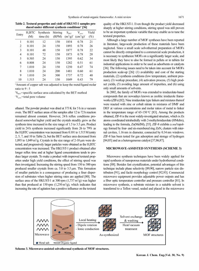
Microwave synthesis techniques have been widely applied forrapid synthesis of nanoporous materials under hydrothermal condi-tions [88]. Besides fast crystallization, potential advantages of thistechnique include phase selectivity [89,90], narrow particle size dis-tribution [91], and facile morphology control [92,93]. Commercialmicrowave equipment provides adjustable power outputs and hasa fiber optic temperature controller and pressure controller [81]. Inmicrowave synthesis, a substrate mixture in a suitable solvent istransferred to a Teflon vessel, sealed and placed in the microwave
Table 2. Textural properties and yield of HKUST-1 samples pro-duced under different synthesis conditionsa [36]
EntryH3BTC
(M)
Synthesis
time (h)
Stirring
(RPM)
SBET
(m2/g)bVpore
(cm3/g)cYield
(%)
01 0.101 12 150 1854 0.78 21
02 0.101 24 150 1893 0.78 26
03 0.101 48 150 1877 0.78 22
04 0.101 72 150 1873 0.78 20
05 0.505 24 150 1395 0.62 34
06 0.808 24 150 1282 0.51 61
07 1.010 24 150 1250 0.47 74
08 1.010 24 200 1481 0.60 61
09 1.010 24 300 1737 0.72 40
10 1.515 24 150 1049 0.43 79
aAmount of copper salt was adjusted to keep the metal/ligand molar
ratio to 9 : 5bSBET=specific surface area calculated by the BET methodcVpore=total pore volume
Scheme 3. Microwave-assisted solvothermal synthesis of MOF structures.
1672 Y.-R. Lee et al.
September, 2013
unit, and heated for the appropriate time at the set temperature. Themicrowave approach, where an applied oscillating electric field iscoupled with the permanent dipole moment of the molecules in thesynthesis medium inducing molecular rotations, results in rapid heat-ing of the liquid phase [94,95].
The first reported microwave synthesis of MOFs was Cr-MIL-100[62]. The compound was synthesized in 4 h at 220 oC with 44%yield, which is comparable with that of conventional hydrothermalsynthesis (220 oC and 4 days). The author expanded this method tosynthesis of Cr-MIL-101 at 210 oC in less than 60 min, and reportedsimilar physicochemical and textural properties compared with thestandard material synthesized using the conventional electrical heat-ing method [96]. MOF-5 was also synthesized by applying micro-wave irradiation: increases in microwave irradiation time, powerlevel, and concentration of the substrates beyond an optimal condi-tion led to a reduction in synthesis time at the expense of crystalquality [27]. Microwave-assisted heating was found to be the methodof choice to rapidly synthesize HKUST-1 crystals in the range of10-20µm in high yields (~90%) within 1 h [97]. Fe-MIL-53 [59],Fe-MIL-101-NH2 [60], IRMOF-3 (H2BDC-NH2) [61], and ZIF-8(HMeIm) [63] were also synthesized using microwave-assisted syn-thesis method.
Recently, systematic microwave-assisted synthesis of Co-MOF-74 reported [28], in which 0.148 mmol of cobalt nitrate hexahydrate(Co(NO3)2·6H2O, Sigma-Aldrich) and 0.044 mmol of H4DHBDC(Sigma-Aldrich) were dissolved in 18 mL of a mixed solvent (DMF :ethanol : water=1 : 1 : 1 (v/v/v)) and put into a 35 mL tube, sealedwith a rubber septum and placed in a microwave oven (DiscoverS-class, CEM, Maximum power of 300 W). The resulting mixturewas heated to 130 oC, held for 1 h, and then cooled to room tem-perature. The red-orange crystals were separated by centrifuging.After washing with DMF three times, they were placed in metha-nol, which was decanted and replenished four times for two days.The solvent was removed under vacuum at 250 oC for 5 h, yield-ing a dark-purple porous material. The textural properties of Co-MOF-74 samples prepared under various microwave synthesis con-ditions (synthesis temperature, microwave irradiation power level,and synthesis time) are summarized in Table 3. According to theresults, the optimized Co-MOF-74 was synthesized at 130 oC with180 W microwave power level for 1 h (entry 7), which resulted inthe highest textural properties (1,314 m2/g of BET surface area) witha high product yield (ca. 76% based on ligand). Co-MOF-74 (ca.
50µm long and 8µm wide) by microwave heating was significantlysmaller in size than Co-MOF-74 (ca. 300µm long and 70µm wide)solvothermally prepared.
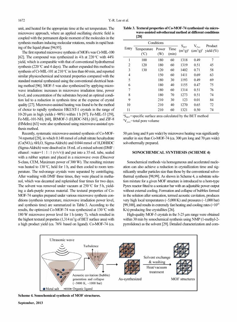
SONOCHEMICAL SYNTHESIS (SCHEME 4)
Sonochemical methods via homogeneous and accelerated nucle-ation can also achieve a reduction in crystallization time and sig-nificantly smaller particles size than those by the conventional solvo-thermal synthesis [98,99]. As shown in Scheme 4, a substrate solu-tion mixture for a given MOF structure is introduced to a horn-typePyrex reactor fitted to a sonicator bar with an adjustable power outputwithout external cooling. Formation and collapse of bubbles formedin the solution after sonication, termed acoustic cavitation, producesvery high local temperatures (~5,000 K) and pressures (~1,000 bar)[99,100], and results in extremely fast heating and cooling rates (>1010
K/s) producing fine crystallites [26].High-quality MOF-5 crystals in the 5-25µm range were obtained
within 30 min by sonochemical synthesis using NMP (1-methyl-2-pyrrolidone) as the solvent [29]. Detailed characterization and com-
Scheme 4. Sonochemical synthesis of MOF structures.
Table 3. Textural properties of Co-MOF-74 synthesized via micro-wave-assisted solvothermal method at different conditions[28]
Entry
ConditionsSBET
(m2/g)aVPore
(cm3/g)bProduct
yield (%)Temperature
(oC)
Power
(W)
Time
(min)
01 100 180 60 1318 0.49 07
02 120 180 60 1319 0.51 45
03 130 120 60 1402 0.71 58
04 150 60 1411 0.69 63
05 180 30 1193 0.49 69
06 180 40 1155 0.47 75
07 180 60 1314 0.51 76
08 180 70 1273 0.51 74
09 210 30 0123 0.01 84
10 210 40 1270 0.65 72
11 210 60 1321 0.50 74
aSBET=specific surface area calculated by the BET methodbVpore=total pore volume
Synthesis of metal-organic frameworks: A mini review 1673
Korean J. Chem. Eng.(Vol. 30, No. 9)
parison with a conventionally synthesized sample showed almostidentical physical properties. HKUST-1 was also prepared usingDMF/EtOH/H2O mixed-solution in an ultrasonic bath [64]. Theproduct formed after 5 min as a nanocrystalline powder (10-40 nm),and increasing the reaction time led to larger crystals (50-200 nm)and higher yields, but further reaction resulted in their partial de-composition. High-quality Mg-MOF-74 crystals (1,640 m2/g BETsurface area) with particle size of ca. 0.6µm were successfully syn-thesized in 1 h by a sonochemical method after triethylamine (TEA)was added as a deprotonating agent. Interestingly, mesopores wereformed, probably due to the competitive binding of TEA to Mg2+
ions [13]. Both interpenetrated and non-interpenetrated MOF struc-tures, i.e., PCN-6/PCN-6’ and IRMOF-9/IRMOF-10, could be syn-thesized by simple control in ultrasonic power levels in sonochemicalsynthesis [31]. At lower power levels, the non-interpenetrated struc-tures (PCN-6’, IRMOF-10) were obtained, intermediate power levelsled to mixtures, and higher power levels to phase-pure interpene-trated structures of the corresponding MOF (PCN-6, IRMOF-9).Uniform well-shaped particles were obtained for all the cases: 1.5-2.0µm for PCN-6’, 4.5-6.0µm for PCN-6, and 5-20µm for IRMOF-9 and -10.
Recently, ZIF-8 was prepared by a sonochemical method underthe pH-adjusted synthesis conditions using NaOH and TEA [37].Inexpensive industrial grade DMF was employed as a solvent. Asubstrate was prepared using 0.67g (2 mmol) of zinc nitrate hexahy-drate (Zn(NO3)2·6H2O, 98%, Sigma-Aldrich) and 0.167 g (2 mmol)of HMeIm (98%, Sigma-Aldrich) in 50 mL of DMF (industrial grade,
DUKSAN, Korea), and stirred vigorously until a clear solution wasobtained. Then, 0.3 to 0.7 mL of TEA (99%, Sigma-Aldrich) wasadded and the resulting solution was transferred to a 70 mL of horn-type reactor fitted to a sonicator having an adjustable power output(maximum 500 W at 20 kHz). After the synthesis, the ZIF-8 sam-ples were washed with DMF and placed in methanol. After filtra-tion, the samples were dried in a vacuum oven (<5×10⁻³ torr) at80 oC. A small amount of TEA as a deprotonating agent was neces-sary to obtain ZIF-8 crystals when the resulting solution was sub-jected to an ultrasonic treatment for 1 h at a 60% power level. Assummarized in Table 4, a ZIF-8 sample with the best textural prop-erties was obtained with 0.5 mL TEA addition (entry 3). The texturalproperties were similar to those of ZIF-8 prepared in solvothermalmethod (entry 1), but sonochemically prepared ZIF-8 was ca. 700nm in size, which was approximately 400 times smaller than ZIF-8 prepared in solvothermal method. The optimum pH for ZIF-8synthesis was ca. 9.0 with 0.5-0.7 mL of TEA. Inferior textural prop-erties were observed (entry 5 in Table 4) when NaOH (aq, 10 M)was tested for pH control instead of TEA, and a small amount ofTEA with NaOH (aq) was used to maintain the textural propertiesof ZIF-8. ZIF-8 was then prepared using five-times as much syn-thesis substrate (entry 6, Table 4). The resulting ZIF-8 exhibited goodtextural properties (BET specific surface area: 1,197 m2/g, total porevolume: 0.60 cm3/g), but the product yield under these conditions waslow (22%). 2.5 mL TEA was apparently not sufficient to achievethe optimum pH of 9.0 established earlier, and increasing the pHusing 10 M NaOH resulted in an immediate improvement in prod-
Table 4. Textural properties of the ZIF-8 sonochemically synthesized for 1 h under different synthesis conditionsa [37]
EntryBatch scale
(mL)
Zn2+
(mmol)aTEA
(mL)
NaOH solution
(10 M, mL)pH
SBET
(m2/g)bVpore
(cm3/g)cSext
(m2/g)dYield
(%)
1e 050 002 - - 6.4 1370 0.51 006.7 60
2 050 002 0.3 - 7.5 0911 0.43 042.4 57
3 050 002 0.5 - 8.8 1300 0.48 013.4 59
4 050 002 0.7 - 9.2 1245 0.42 023.3 56
5 050 002 - 003.8 9.3 0643 0.39 040.9 62
6 050 010 2.5 - 7.1 1197 0.60 045.3 22
7 050 010 2.5 001.0 9.3 1253 0.61 036.7 93
8 050 010 0.8 002.4 9.1 1213 0.67 079.0 96
9 050 010 0.4 003.5 9.0 1223 0.82 100.1 92
10 050 060 0.4 015.0 9.5 1249 0.71 053.7 93
11f 050 030 0.4 007.8 9.1 1454 0.66 015.8 60
12g 050 060 0.4 015.0 9.1 1226 0.51 011.7 80
13 600 720 4.5 132.0 9.2 1141 0.56 021.3 50
14h 600 720 4.5 132.0 9.2 1174 0.50 026.6 85
15i 600 720 4.5 132.0 9.2 0915 0.43 012.6 84
aAmount of zinc salt was adjusted to keep the metal/ligand molar ratio to 2 : 2bSBET=specific surface area calculated by the BET methodcVpore=total pore volumedSext=external surface area calculated by the t-plot methodeZIF-8 synthesized by solvothermal synthesisfZIF-8 synthesized at the condition of Zn2+ : MeIM=1 : 2gZIF-8 synthesized using recycled solvent with extra substrate (Zn2+ and MeIM) addition to maintain the molar ratio to Zn2+ : MeIM=2 : 2hZIF-8 synthesized in 2 hi3 h
1674 Y.-R. Lee et al.
September, 2013
uct yield to 93% (entry 7). Subsequently, the amount of relativelycostly TEA used was decreased steadily from 2.5 to 0.8 (entry 8)and then to 0.4 mL (entry 9). No loss of yield or textural propertieswas observed. The amount of TEA used (HMeIM : TEA=308 : 1)is significantly less than the HMeIM : TEA=1 : 1 reported elsewhere[101]. Thirty times as much substrate was then attempted for ZIF-8synthesis. Acceptable textural properties and 93% yield were ob-tained using 0.4 mL of TEA and balancing the NaOH concentra-tion to control the pH (entry 10). The substrate ratio used in thisstudy (Zn2+ : HMeIM=2 : 2) has been universally employed by mostof the research groups [55,86,102]. At the Zn2+ : MeIM of 1 : 2 (entry11 in Table 4), the textural properties were excellent but the prod-uct yield was unsatisfactory (60%). Synthesis using the recycledmother liquid at Zn2+ : MeIM=2 : 2 with addition of make-up zincsalt and ligand to keep the substrate ratio as the fresh synthesis condi-tion (entry 12) had shown acceptable textural properties (BET spe-cific surface area: 1,226 m2/g, total pore volume: 0.51 cm3/g) in goodyield (80%). Finally, sonochemical synthesis was carried out on a1 L batch scale. ZIF-8 prepared in 2 h produced good textural proper-ties in 85% yield (entry 14). The space-time yield (STY: kilogramsof product per cubic meter of reaction mixture per day, kg/m3·day)[103] of the ZIF-8 in entry 14 was 2,140 kg/m3·day, which was ca.1,200 times higher than the conventional solvothermal synthesis.
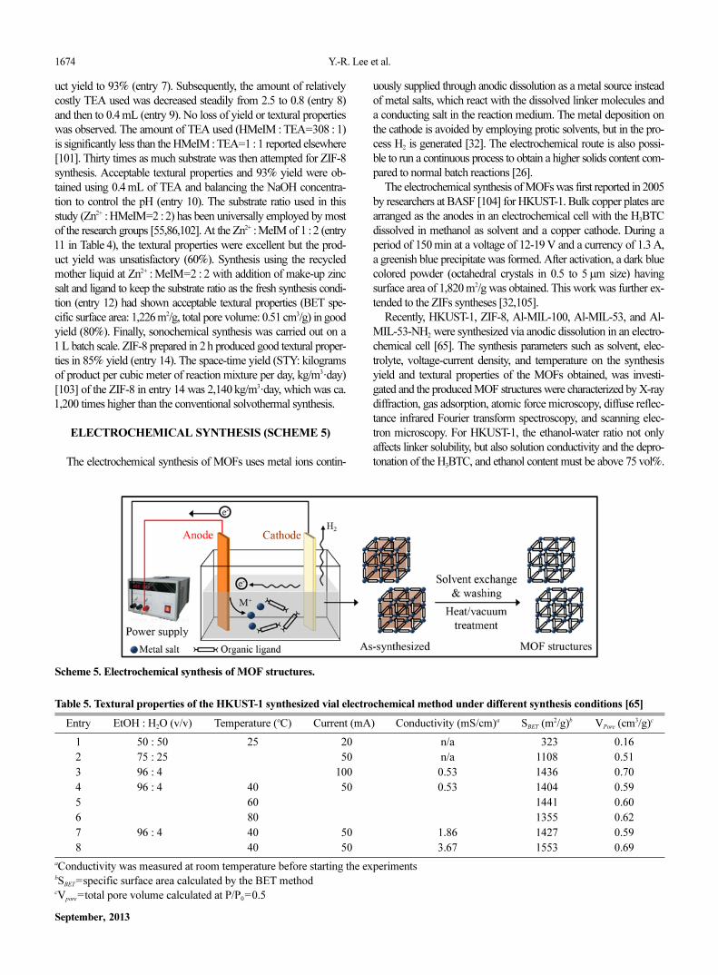
ELECTROCHEMICAL SYNTHESIS (SCHEME 5)
The electrochemical synthesis of MOFs uses metal ions contin-
Scheme 5. Electrochemical synthesis of MOF structures.
Table 5. Textural properties of the HKUST-1 synthesized vial electrochemical method under different synthesis conditions [65]
Entry EtOH : H2O (v/v) Temperature (oC) Current (mA) Conductivity (mS/cm)a SBET (m2/g)b VPore (cm3/g)c
1 50 : 50 25 020 n/a 0323 0.16
2 75 : 25 050 n/a 1108 0.51
3 96 : 40 100 0.53 1436 0.70
4 96 : 40 40 050 0.53 1404 0.59
5 60 1441 0.60
6 80 1355 0.62
7 96 : 40 40 050 1.86 1427 0.59
8 40 050 3.67 1553 0.69
aConductivity was measured at room temperature before starting the experimentsbSBET=specific surface area calculated by the BET methodcVpore=total pore volume calculated at P/P0=0.5
uously supplied through anodic dissolution as a metal source insteadof metal salts, which react with the dissolved linker molecules anda conducting salt in the reaction medium. The metal deposition onthe cathode is avoided by employing protic solvents, but in the pro-cess H2 is generated [32]. The electrochemical route is also possi-ble to run a continuous process to obtain a higher solids content com-pared to normal batch reactions [26].
The electrochemical synthesis of MOFs was first reported in 2005by researchers at BASF [104] for HKUST-1. Bulk copper plates arearranged as the anodes in an electrochemical cell with the H3BTCdissolved in methanol as solvent and a copper cathode. During aperiod of 150 min at a voltage of 12-19 V and a currency of 1.3 A,a greenish blue precipitate was formed. After activation, a dark bluecolored powder (octahedral crystals in 0.5 to 5µm size) havingsurface area of 1,820 m2/g was obtained. This work was further ex-tended to the ZIFs syntheses [32,105].
Recently, HKUST-1, ZIF-8, Al-MIL-100, Al-MIL-53, and Al-MIL-53-NH2 were synthesized via anodic dissolution in an electro-chemical cell [65]. The synthesis parameters such as solvent, elec-trolyte, voltage-current density, and temperature on the synthesisyield and textural properties of the MOFs obtained, was investi-gated and the produced MOF structures were characterized by X-raydiffraction, gas adsorption, atomic force microscopy, diffuse reflec-tance infrared Fourier transform spectroscopy, and scanning elec-tron microscopy. For HKUST-1, the ethanol-water ratio not onlyaffects linker solubility, but also solution conductivity and the depro-tonation of the H3BTC, and ethanol content must be above 75 vol%.
Synthesis of metal-organic frameworks: A mini review 1675
Korean J. Chem. Eng.(Vol. 30, No. 9)
At low ethanol content, a different coordination polymer called cat-ena-triaqua-mu-(1,3,5-benzenetricarboxylate)-copper(II) is formed(entry 1 in Table 5). Standard synthesis solutions of 15 mmol (3.15 g)of H3BTC with 33 mmol (1.038 g) of MTBS (tributylmethylam-monium methyl sulfate) dissolved in 100 mL 96 vol% EtOH wereheated to four different temperatures in contact with two copperelectrodes separated by 3 cm, and then 100 mA (entry 3 in Table 5)and 50 mA (entry 4-6 in Table 5) are passed through the systemfor 1 h. On average ~100 mg of dried HKUST-1 is obtained fromeach synthesis, and the surface areas correspond well to those givenin the literature (BET area=1,400 m2/g, pore volume=0.6 cm3/g).No Cu2O impurity is observed. By controlling the current density,the Cu2+ concentration close to the electrode can be tuned. How-ever, current density and voltage are interrelated through the sys-tem geometry and the solution conductivity. A standard synthesissolution displayed a conductivity of ca. 530µS/cm (entry 4 in Table5). By increasing the electrolyte concentration 5 and 15 times, con-ductivity can be increased to 1.86 and 3.6 mS/cm, respectively (entries7 and 8). Increasing conductivity improved the yield because lessenergy is required to overcome the ohmic drop in the solution andcan therefore be used to dissolve the electrode. As expected, higherconductivity results in higher yield. The high impact of the ohmicdrop is remarkable because a 3.5 times increase in conductivity onlyincreases the yield by a factor 1.6; and a 7 times increase in conduc-tivity only increases the yield by a factor of 2.
It was claimed that electrochemical MOF synthesis has severaladvantages: (1) faster synthesis at lower temperatures than conven-tional synthesis, (2) metal salts are not needed and therefore sepa-ration of anions such as NO3− or Cl− from the synthesis solution isnot needed prior to solvent recycle, and (3) virtual total utilizationof the linker can be achieved in combination with high Faraday effi-ciencies [65]. They also found that the electrochemically synthe-sized MIL-53 sample does not exhibit the characteristic breathingeffect during CO2 adsorption at high-pressure condition [52,65].
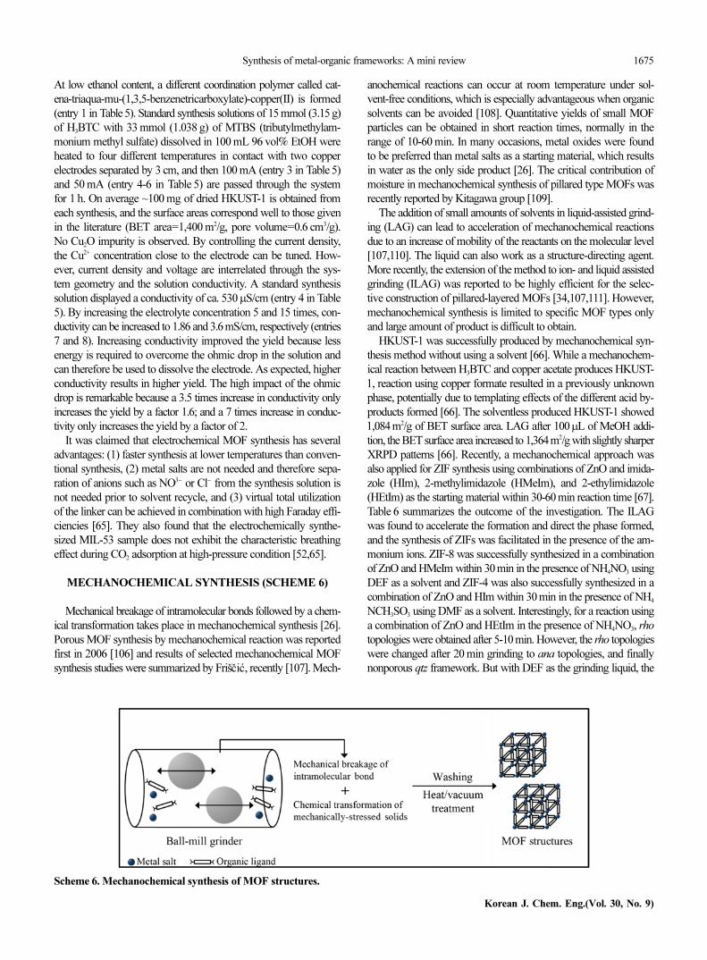
MECHANOCHEMICAL SYNTHESIS (SCHEME 6)
Mechanical breakage of intramolecular bonds followed by a chem-ical transformation takes place in mechanochemical synthesis [26].Porous MOF synthesis by mechanochemical reaction was reportedfirst in 2006 [106] and results of selected mechanochemical MOFsynthesis studies were summarized by Friš i , recently [107]. Mech-
anochemical reactions can occur at room temperature under sol-vent-free conditions, which is especially advantageous when organicsolvents can be avoided [108]. Quantitative yields of small MOFparticles can be obtained in short reaction times, normally in therange of 10-60 min. In many occasions, metal oxides were foundto be preferred than metal salts as a starting material, which resultsin water as the only side product [26]. The critical contribution ofmoisture in mechanochemical synthesis of pillared type MOFs wasrecently reported by Kitagawa group [109].
The addition of small amounts of solvents in liquid-assisted grind-ing (LAG) can lead to acceleration of mechanochemical reactionsdue to an increase of mobility of the reactants on the molecular level[107,110]. The liquid can also work as a structure-directing agent.More recently, the extension of the method to ion- and liquid assistedgrinding (ILAG) was reported to be highly efficient for the selec-tive construction of pillared-layered MOFs [34,107,111]. However,mechanochemical synthesis is limited to specific MOF types onlyand large amount of product is difficult to obtain.
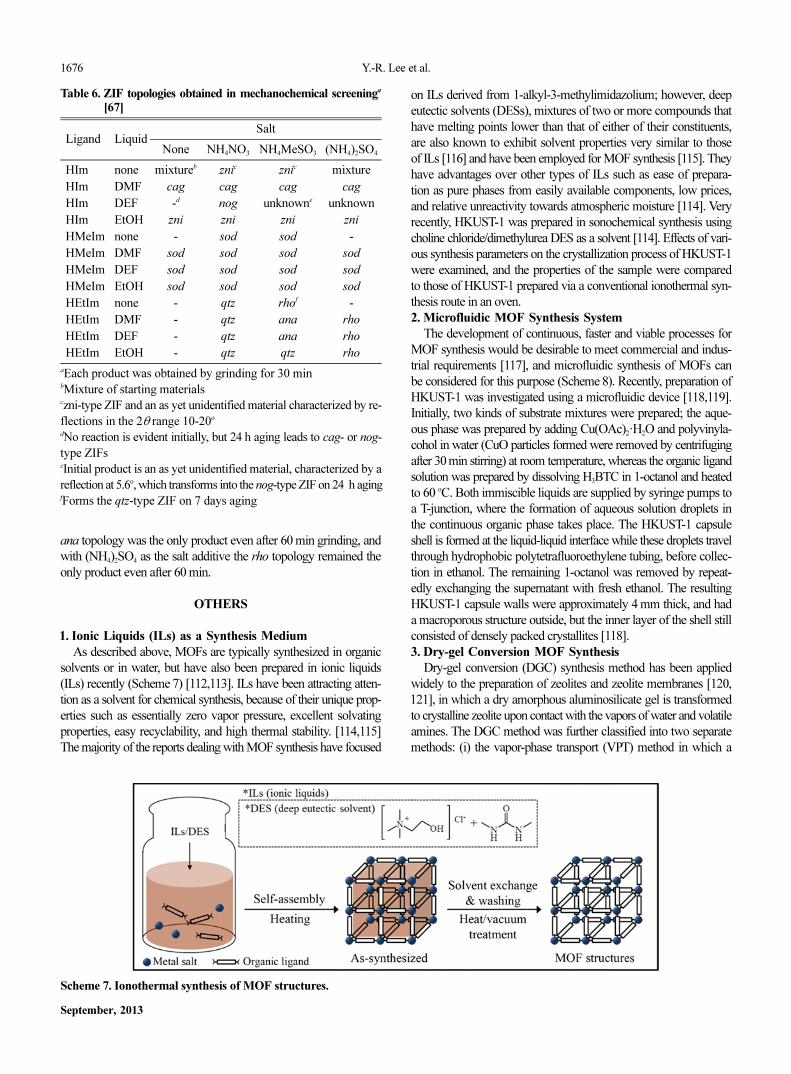
HKUST-1 was successfully produced by mechanochemical syn-thesis method without using a solvent [66]. While a mechanochem-ical reaction between H3BTC and copper acetate produces HKUST-1, reaction using copper formate resulted in a previously unknownphase, potentially due to templating effects of the different acid by-products formed [66]. The solventless produced HKUST-1 showed1,084 m2/g of BET surface area. LAG after 100µL of MeOH addi-tion, the BET surface area increased to 1,364m2/g with slightly sharperXRPD patterns [66]. Recently, a mechanochemical approach wasalso applied for ZIF synthesis using combinations of ZnO and imida-zole (HIm), 2-methylimidazole (HMeIm), and 2-ethylimidazole(HEtIm) as the starting material within 30-60 min reaction time [67].Table 6 summarizes the outcome of the investigation. The ILAGwas found to accelerate the formation and direct the phase formed,and the synthesis of ZIFs was facilitated in the presence of the am-monium ions. ZIF-8 was successfully synthesized in a combinationof ZnO and HMeIm within 30 min in the presence of NH4NO3 usingDEF as a solvent and ZIF-4 was also successfully synthesized in acombination of ZnO and HIm within 30 min in the presence of NH4
NCH3SO3 using DMF as a solvent. Interestingly, for a reaction usinga combination of ZnO and HEtIm in the presence of NH4NO3, rhotopologies were obtained after 5-10 min. However, the rho topologieswere changed after 20 min grinding to ana topologies, and finallynonporous qtz framework. But with DEF as the grinding liquid, thešc ác
Scheme 6. Mechanochemical synthesis of MOF structures.
1676 Y.-R. Lee et al.
September, 2013
ana topology was the only product even after 60 min grinding, andwith (NH4)2SO4 as the salt additive the rho topology remained theonly product even after 60 min.
OTHERS
1. Ionic Liquids (ILs) as a Synthesis Medium
As described above, MOFs are typically synthesized in organicsolvents or in water, but have also been prepared in ionic liquids(ILs) recently (Scheme 7) [112,113]. ILs have been attracting atten-tion as a solvent for chemical synthesis, because of their unique prop-erties such as essentially zero vapor pressure, excellent solvatingproperties, easy recyclability, and high thermal stability. [114,115]The majority of the reports dealing with MOF synthesis have focused
on ILs derived from 1-alkyl-3-methylimidazolium; however, deepeutectic solvents (DESs), mixtures of two or more compounds thathave melting points lower than that of either of their constituents,are also known to exhibit solvent properties very similar to thoseof ILs [116] and have been employed for MOF synthesis [115]. Theyhave advantages over other types of ILs such as ease of prepara-tion as pure phases from easily available components, low prices,and relative unreactivity towards atmospheric moisture [114]. Veryrecently, HKUST-1 was prepared in sonochemical synthesis usingcholine chloride/dimethylurea DES as a solvent [114]. Effects of vari-ous synthesis parameters on the crystallization process of HKUST-1were examined, and the properties of the sample were comparedto those of HKUST-1 prepared via a conventional ionothermal syn-thesis route in an oven.2. Microfluidic MOF Synthesis System
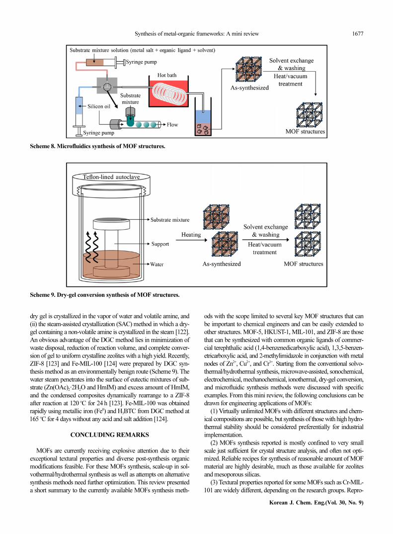
The development of continuous, faster and viable processes forMOF synthesis would be desirable to meet commercial and indus-trial requirements [117], and microfluidic synthesis of MOFs canbe considered for this purpose (Scheme 8). Recently, preparation ofHKUST-1 was investigated using a microfluidic device [118,119].Initially, two kinds of substrate mixtures were prepared; the aque-ous phase was prepared by adding Cu(OAc)2·H2O and polyvinyla-cohol in water (CuO particles formed were removed by centrifugingafter 30 min stirring) at room temperature, whereas the organic ligandsolution was prepared by dissolving H3BTC in 1-octanol and heatedto 60 oC. Both immiscible liquids are supplied by syringe pumps toa T-junction, where the formation of aqueous solution droplets inthe continuous organic phase takes place. The HKUST-1 capsuleshell is formed at the liquid-liquid interface while these droplets travelthrough hydrophobic polytetrafluoroethylene tubing, before collec-tion in ethanol. The remaining 1-octanol was removed by repeat-edly exchanging the supernatant with fresh ethanol. The resultingHKUST-1 capsule walls were approximately 4 mm thick, and hada macroporous structure outside, but the inner layer of the shell stillconsisted of densely packed crystallites [118].3. Dry-gel Conversion MOF Synthesis
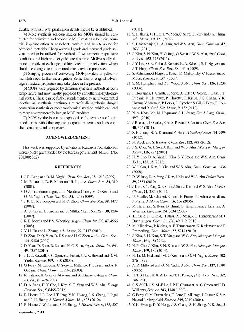
Dry-gel conversion (DGC) synthesis method has been appliedwidely to the preparation of zeolites and zeolite membranes [120,121], in which a dry amorphous aluminosilicate gel is transformedto crystalline zeolite upon contact with the vapors of water and volatileamines. The DGC method was further classified into two separatemethods: (i) the vapor-phase transport (VPT) method in which a
Table 6. ZIF topologies obtained in mechanochemical screeninga
[67]
Ligand LiquidSalt
None NH4NO3 NH4MeSO3 (NH4)2SO4
HIm none mixtureb znic znic mixture
HIm DMF cag cag cag cag
HIm DEF -d nog unknowne unknown
HIm EtOH zni zni zni zni
HMeIm none - sod sod -
HMeIm DMF sod sod sod sod
HMeIm DEF sod sod sod sod
HMeIm EtOH sod sod sod sod
HEtIm none - qtz rhof -
HEtIm DMF - qtz ana rho
HEtIm DEF - qtz ana rho
HEtIm EtOH - qtz qtz rho
aEach product was obtained by grinding for 30 minbMixture of starting materialsczni-type ZIF and an as yet unidentified material characterized by re-
flections in the 2θ range 10-20o
dNo reaction is evident initially, but 24 h aging leads to cag- or nog-
type ZIFseInitial product is an as yet unidentified material, characterized by a
reflection at 5.6o, which transforms into the nog-type ZIF on 24 h agingfForms the qtz-type ZIF on 7 days aging
Scheme 7. Ionothermal synthesis of MOF structures.
Synthesis of metal-organic frameworks: A mini review 1677
Korean J. Chem. Eng.(Vol. 30, No. 9)
dry gel is crystallized in the vapor of water and volatile amine, and(ii) the steam-assisted crystallization (SAC) method in which a dry-gel containing a non-volatile amine is crystallized in the steam [122].An obvious advantage of the DGC method lies in minimization ofwaste disposal, reduction of reaction volume, and complete conver-sion of gel to uniform crystalline zeolites with a high yield. Recently,ZIF-8 [123] and Fe-MIL-100 [124] were prepared by DGC syn-thesis method as an environmentally benign route (Scheme 9). Thewater steam penetrates into the surface of eutectic mixtures of sub-strate (Zn(OAc)2·2H2O and HmIM) and excess amount of HmIM,and the condensed composites dynamically rearrange to a ZIF-8after reaction at 120 oC for 24 h [123]. Fe-MIL-100 was obtainedrapidly using metallic iron (Fe0) and H3BTC from DGC method at165 oC for 4 days without any acid and salt addition [124].
CONCLUDING REMARKS
MOFs are currently receiving explosive attention due to theirexceptional textural properties and diverse post-synthesis organicmodifications feasible. For these MOFs synthesis, scale-up in sol-vothermal/hydrothermal synthesis as well as attempts on alternativesynthesis methods need further optimization. This review presenteda short summary to the currently available MOFs synthesis meth-
ods with the scope limited to several key MOF structures that canbe important to chemical engineers and can be easily extended toother structures. MOF-5, HKUST-1, MIL-101, and ZIF-8 are thosethat can be synthesized with common organic ligands of commer-cial terephthalic acid (1,4-benzenedicarboxylic acid), 1,3,5-benzen-etricarboxylic acid, and 2-methylimidazole in conjunction with metalnodes of Zn2+, Cu2+, and Cr3+. Starting from the conventional solvo-thermal/hydrothermal synthesis, microwave-assisted, sonochemical,electrochemical, mechanochemical, ionothermal, dry-gel conversion,and microfluidic synthesis methods were discussed with specificexamples. From this mini review, the following conclusions can bedrawn for engineering applications of MOFs:
(1) Virtually unlimited MOFs with different structures and chem-ical compositions are possible, but synthesis of those with high hydro-thermal stability should be considered preferentially for industrialimplementation.
(2) MOFs synthesis reported is mostly confined to very smallscale just sufficient for crystal structure analysis, and often not opti-mized. Reliable recipes for synthesis of reasonable amount of MOFmaterial are highly desirable, much as those available for zeolitesand mesoporous silicas.
(3) Textural properties reported for some MOFs such as Cr-MIL-101 are widely different, depending on the research groups. Repro-
Scheme 8. Microfluidics synthesis of MOF structures.
Scheme 9. Dry-gel conversion synthesis of MOF structures.
1678 Y.-R. Lee et al.
September, 2013
ducible synthesis with purification details should be established.(4) More synthesis scale-up studies for MOFs should be con-
ducted for optimized and economic MOF materials for their indus-trial implementation as adsorbent, catalyst, and as a template foradvanced materials. Cheap organic ligands and industrial grade sol-vents need to be utilized for synthesis. Low temperature/pressureconditions and high product yields are desirable. MOFs usually de-mands for solvent exchange and high vacuum for activation, whichshould be changed to a more moderate activation processes.
(5) Shaping process of converting MOF powders to pellets ormonolith need further investigation. Some loss of original advan-tage in textural properties may take place in the process.
(6) MOFs were prepared by diffusion synthesis methods at roomtemperature and now mostly prepared by solvothermal/hydrother-mal routes. These can be further supplemented by newly-attemptedionothermal synthesis, continuous microfluidic synthesis, dry-gelconversion synthesis or mechanochemical method, which can leadto more environmentally benign MOF products.
(7) MOF synthesis can be expanded to the synthesis of com-bined forms with other organic inorganic materials such as core-shell structures and composites.
ACKNOWLEDGEMENT
This work was supported by a National Research Foundation ofKorea (NRF) grant funded by the Korean government (MEST) (No.2013005862).
REFERENCES
1. J. R. Long and O. M. Yaghi, Chem. Soc. Rev., 38, 1213 (2009).
2. M. Eddaoudi, D. B. Moler and H. Li, Acc. Chem. Res., 34, 319
(2001).
3. D. J. Tranchemontagne, J. L. Mendoza-Cortes, M. O’Keeffe and
O. M. Yaghi, Chem. Soc. Rev., 38, 1257 (2009).
4. J. R. Li, R. J. Kuppler and H. C. Zhou, Chem. Soc. Rev., 38, 1477
(2009).
5. A. U. Czaja, N. Trukhan and U. Müller, Chem. Soc. Rev., 38, 1284
(2009).
6. R. E. Morris and P. S. Wheatley, Angew. Chem. Int. Ed., 47, 4966
(2008).
7. Y. H. Hu and L. Zhang, Adv. Mater., 22, E117 (2010).
8. D. Zhao, D. Q. Yuan, D. F. Sun and H. C. Zhou, J. Am. Chem. Soc.,
131, 9186 (2009).
9. D. Yuan, D. Zhao, D. Sun and H. C. Zhou, Angew. Chem., Int. Ed.,
49, 5357 (2010).
10. J. L. C. Rowsell, E. C. Spencer, J. Eckert, J. A. K. Howard and O. M.
Yaghi, Science, 309, 1350 (2005).
11. G. Férey, M. Latroche, C. Serre, F. Millange, T. Loiseau and A. P.
Guégan, Chem. Commun., 2976 (2003).
12. R. Kitaura, K. Seki, G. Akiyama and S. Kitagawa, Angew. Chem.
Int. Ed., 42, 428 (2003).
13. D. A. Yang, H. Y. Cho, J. Kim, S. T. Yang and W. S. Ahn, Energy
Environ. Sci., 5, 6465 (2012).
14. E. Haque, J. E. Lee, I. T. Jang, Y. K. Hwang, J. S. Chang, J. Jegal
and S. H. Jhung, J. Hazard. Mater., 181, 535 (2010).
15. E. Haque, J. W. Jun and S. H. Jhung, J. Hazard. Mater., 185, 507
(2011).
16. S. H. Jhung, J. H. Lee, J. W. Yoon, C. Serre, G. Férey and J. S. Chang,
Adv. Mater., 19, 121 (2007).
17. S. Bhattacharjee, D. A. Yang and W. S. Ahn, Chem. Commun., 47,
3637 (2011).
18. J. Kim, S. N. Kim, H. G. Jang, G. Seo and W. S. Ahn, Appl. Catal.
A: Gen., 453, 175 (2013).
19. J. Y. Lee, O. K. Farha, J. Roberts, K. A. Scheidt, S. T. Nguyen and
J. T. Hupp, Chem. Soc. Rev., 38, 1450 (2009).
20. S. Achmann, G. Hagen, J. Kita, I. M. Malkowsky, C. Kiener and R.
Moos, Sensors, 9, 1574 (2009).
21. S. M. Humphrey and P. T. Wood, J. Am. Chem. Soc., 126, 13236
(2004).
22. P. Horcajada, T. Chalati, C. Serre, B. Gillet, C. Sebrie, T. Baati, J. F.
Eubank, D. Heurtaux, P. Clayette, C. Kreuz, J. S. Chang, Y. K.
Hwang, V. Marsaud, P. Bories, L. Cynober, S. Gil, G. Férey, P. Cou-
vreur and R. Gref, Nat. Mater., 9, 172 (2010).
23. N. A. Khan, Md. M. Haque and S. H. Jhung, Eur. J. Inorg. Chem.,
4975 (2010).
24. J. Rocha, L. D. Carlos, F. A. A. Paz and D. Ananias, Chem. Soc. Rev.,
40, 926 (2011).
25. S. H. Jhung, N. A. Khan and Z. Hasan, CrystEngComm., 14, 7099
(2012).
26. N. Stock and S. Biswas, Chem. Rev., 112, 933 (2012).
27. J. S. Choi, W. J. Son, J. Kim and W. S. Ahn, Micropor. Mesopor.
Mater., 116, 727 (2008).
28. H. Y. Cho, D. A. Yang, J. Kim, S. Y. Jeong and W. S. Ahn, Catal.
Today, 185, 35 (2012) .
29. W. J. Son, J. Kim, J. Kim and W. S. Ahn, Chem. Commun., 6336
(2008).
30. D.W. Jung, D.A. Yang, J. Kim, J. Kim and W.S. Ahn, Dalton Trans.,
39, 2883 (2010).
31. J. Kim, S. T. Yang, S.B. Choi, J. Sim, J. Kim and W.S. Ahn, J. Mater.
Chem., 21, 3070 (2011).
32. U. Mueller, M. Schubert, F. Teich, H. Puetter, K. Schierle-Arndt and
J. Pastre, J. Mater. Chem., 16, 626 (2006).
33. M. Hartmann, S. Kunz, D. Himsl, O. Tangermann, S. Ernst and A.
Wagener, Langmuir, 24, 8634 (2008).
34. T. Friš i , D. G. Reid, I. Halasz, R. S. Stein, R. E. Dinnebier and M. J.
Duer, Angew. Chem. Int. Ed., 49, 712 (2010).
35. M. Klimakow, P. Klobes, A. F. Thüunemann, K. Rademann and F.
Emmerling, Chem. Mater., 22, 5216 (2010).
36. J. Kim, S. H. Kim, S. T. Yang and W. S. Ahn, Micropor. Mesopor.
Mater., 161, 48 (2012).
37. H. Y. Cho, J. Kim, S. N. Kim and W. S. Ahn, Micropor. Mesopor.
Mater., 169, 180 (2013).
38. H. Li, M. Eddaoudi, M. O’Keeffe and O. M. Yaghi, Nature, 402,
276 (1999).
39. A. R. Millward and O. M. Yaghi, J. Am. Chem. Soc., 127, 17998
(2005).
40. N. T. S. Phan, K. K. A. Le and T. D. Phan, Appl. Catal. A: Gen., 382,
246 (2010).
41. S. S.-Y. Chui, S. M.-F. Lo, J. P. H. Charmant, A. G. Orpen and I. D.
Williams, Science, 283, 1148 (1999).
42. G. Férey, C. M. Drazniekes, C. Serre, F. Millange, J. Dutour, S. Sur-
blé and I. Margiolaki, Science, 309, 2040 (2005).
43. Y. K. Hwang, D. Y. Hong, J. S. Chang, S. H. Jhung, Y. K. Seo, J.
šc ác
Synthesis of metal-organic frameworks: A mini review 1679
Korean J. Chem. Eng.(Vol. 30, No. 9)
Kim, A. Vimony, M. Daturi, C. Serre and G. Férey, Angew. Chem.
Int. Ed., 47, 4144 (2008).
44. J. Kim, S. Bhattacharjee, K. E. Jeong, S. Y. Jeong and W. S. Ahn,
Chem. Commun., 3904 (2009).
45. P. Horcajada, C. Serre, M. V. Regí, M. Sebban, F. Taulelle and G.
Férey, Angew. Chem. Int. Ed., 45, 5974 (2006).
46. A. Henschel, K. Gedrich, R. Kraehnertb and S. Kaskel, Chem. Com-
mun., 4192 (2008).
47. J. Gascon, U. Aktay, M. D. Hernandez-Alonso, G. P. M. van Klink
and F. Kapteijn, J. Catal., 261, 75 (2009).
48. D. Britt, H. Furukawa, B. Wang, T.G. Glover and O.M. Yaghi, PNAS,
106, 20637 (2009).
49. S. R. Caskey, A. G. Wong-Foy and A. J. Matzger, J. Am. Chem. Soc.,
130, 10870 (2008).
50. C. Serre, F. Millange, C. Thouvenot, M. Nogués, G. Marsolier, D.
Louër and G. Férey, J. Am. Chem. Soc., 124, 13519 (2002).
51. S. Couck, J. F. M. Denayer, G. V. Baron, T. Rémy, J. Gascon and F.
Kapteijn, J. Am. Chem. Soc., 131, 6326 (2009).
52. J. Kim, W. Y. Kim and W. S. Ahn, Fuel, 102, 574 (2012).
53. P. Horcajada, S. Surblé, C. Serre, D. Y. Hong, Y. K. Seo, J. S. Chang,
J. M. Grenèche, I. Margiolaki and G. Férey, Chem. Commun., 2820
(2007).
54. M. Kim and S. M. Cohen, CrystEngComm., 14, 4096 (2012).
55. K. S. Park, Z. Ni, A. P. Côté, J. Y. Choi, R. Huang, F. J. Uribe-Romo,
H. K. Chae, M. O’Keeffe and O.M. Yaghi, PNAS, 103, 10186 (2006).
56. R. Banerjee, A. Phan, B. Wang, C. Knobler, H. Furukawa, M.
O’Keeffe and O. M. Yaghi, Science, 319, 939 (2008).
57. M. Eddaoudi, J. Kim, N. Rosi, D. Vodak, J. Wachter, M. O’Keeffe
and O. M. Yaghi, Science, 295, 469 (2002).
58. H. R. Abid, H. Tian, H. M. Ang, M. O. Tade, C. E. Buckley and S.
Wang, Chem. Eng. J., 187, 415 (2012).
59. K. M. L. Taylor-Pashow, J. D. Rocca, Z. Xie, S. Tran and W. Lin, J.
Am. Chem. Soc., 131, 14261 (2009).
60. Z. Ni and R. I. Masel, J. Am. Chem. Soc., 128, 12394 (2006).
61. Y. K. Seo, G. Hundal, I. T. Jang, Y. K. Hwang, C. H. Jun and J. S.
Chang, Micropor. Mesopor. Mater., 119, 331 (2009).
62. S. H. Jhung, J. H. Lee and J. S. Chang, Bull. Korean Chem. Soc.,
26, 880 (2005).
63. J. H. Park, S. H. Park and S. H. Jhung, J. Korean Chem. Soc., 53,
553 (2009).
64. Z. Q. Li, L. G. Qiu, T. Su, Y. Wu, W. Wang, Z. Y. Wu and X. Jiang,
Mater. Lett., 63, 78 (2009).
65. A. M. Joaristi, J. Juan-AlcanÞiz, P. Serra-Crespo, F. Kapteijn and J.
Gascon, Cryst. Growth Des., 12, 3489 (2012).
66. A. Pichon and S. L. James, CrystEngComm., 10, 1839 (2008).
67. P. J. Beldon, L. Fábián, R.S. Stein, A. Thirumurugan, A.K. Cheetham
and T. Friš i , Angew. Chem. Int. Ed., 49, 9640 (2010).
68. N. Stock, Micropor. Mesopor. Mater., 129, 287 (2010).
69. D. Kim, T. B. Lee, S. B. Choi, J. H. Yoon, J. Kim and S. H. Choi,
Chem. Phys. Lett., 420, 256 (2006).
70. D. J. Tranchemontagne, J. R. Hunt and O. M. Yaghi, Tetrahedron,
64, 8553 (2008).
71. D. Y. Hong, Y. K. Hwang, C. Serre, G. Férey and J. S. Chang, Adv.
Funct. Mater., 19, 1537 (2009).
72. Y. Pan, B. Yuan, Y. Li and D. He, Chem. Commun., 46, 2280 (2010).
73. J. Yang, Q. Zhao, J. Li and J. Dong, Micropor. Mesopor. Mater., 130,
174 (2010).
74. N. A. Khan, I. J. Kang, H. Y. Seok and S. H. Jhung, Chem. Eng.
J., 166, 1152 (2011).
75. T. Loiseau, C. Serre, C. Huguenard, G. Fink, F. Taulelle, M. Henry,
T. Bataille and G. Férey, Chem. Eur. J., 10, 1373 (2004).
76. N. A. Ramsahye, G. Maurin, S. Bourrelly, P. Llewellyn, T. Loiseau
and G. Férey, Phys. Chem. Chem. Phys., 9, 1059 (2007).
77. M. Kandiah, M. H. Nilsen, S. Usseglio, S. Jakobsen, U. Olsbye,
M. Tilset, C. Larabi, E. A. Quadrelli, F. Bonino and K. P. Lillerud,
Chem. Mater., 22, 6632 (2010).
78. Q. M. Wang, D. Shen, M. Bulow, M. L. Lau, S. Deng, F. R. Fitch,
N. O. Lemcoff and J. Semanscin, Micropor. Mesopor. Mater., 55,
217 (2002).
79. K. Schlichte, T. Kratzke and S. Kaskel, Micropor. Mesopor. Mater.,
73, 81 (2004).
80. T. Mateovic, B. Kriznar, M. Bogataj and A. Mrhar, J. Microencap-
sulation, 19, 29 (2002).
81. J. Kim, H. Y. Cho and W. S. Ahn, Catal. Survey Asia, 16, 106
(2012).
82. Y. Q. Tian, C. X. Cai, Y. Ji, X. Z. You, S. M. Peng and G. H. Lee,
Angew. Chem., Int. Ed., 41, 1384 (2002).
83. R. Banerjee, A. Phan, B. Wang, C. Knobler, H. Furukawa, M.
O’Keeffe and O. M. Yaghi, Science, 319, 939 (2008).
84. H. Wu, W. Zhou and T. Yildirim, J. Am. Chem. Soc., 129, 5314
(2007).
85. B. Assfour, S. Leoni and G. Seifer, J. Phys. Chem. C, 114, 13381
(2010).
86. U. P. N. Tran, K. K. A. Le and N. T. S. Phan, ACS Catal., 1, 120
(2011).
87. C. M. Miralda, E. E. Macias, M. Zhu, P. Ratnasamy and M. A.
Carreon, ACS Catal., 2 180 (2012).
88. S. E. Park, J. S. Chang, Y. K. Hwang, D. S. Kim, S. H. Jhung and
J. S. Hwang, Catal. Survey Asia, 8, 91 (2004).
89. S. H. Jhung, J. S. Chang, J. S. Hwang and S. E. Park, Micropor.
Mesopor. Mater., 64, 33 (2003).
90. S. H. Jhung, J. H. Lee, J. W. Yoon, J. S. Hwang, S. E. Park and J. S.
Chang, Micropor. Mesopor. Mater., 80, 147 (2005).
91. K. K. Kang, C. H. Park and W. S. Ahn, Catal. Lett., 59, 45 (1999).
92. S. H. Jhung, J. S. Chang, Y. K. Hwang and S. E. Park, J. Mater.
Chem., 14, 280 (2004).
93. Y. K. Hwang, J. S. Chang, S. E. Park, D. S. Kim, Y. U. Kwon, S. H.
Jhung, J. S. Hwang and M. S. Park, Angew. Chem. Int. Ed., 44, 557
(2005).
94. R. Kerner, O. Palchik and A. Gedanken, Chem. Mater., 13, 1413
(2001).
95. Y. P. Xu, Z. J. Tian, S. J. Wang, Y. Hu, L. Wang, B. C. Wang, Y. C.
Ma, L. Hou, J. Y. Yu and L. W. Lin, Angew. Chem. Int. Ed., 45,
3965 (2006).
96. S. H. Jhung, J. H. Lee, J. W. Yoon, C. Serre, G. Férey and J. S.
Chang, Adv. Mater., 19, 121 (2007).
97. M. Schlesinger, S. Schulze, M. Hietschold and M. Mehring,
Micropor. Mesopor. Mater., 132, 121 (2010).
98. K. S. Suslick, S. B. Choe, A. A. Cichowlas and M. W. Grinstaff,
Nature, 353, 414 (1991).
99. A. Gedanken, Ultrason. Sonochem., 11, 47 (2004).
100. K. S. Suslick, D. A. Hammerton and R. E. Cline, J. Am. Chem.
Soc., 108, 5641 (1986).
101. A. F. Gross, E. Sherman and J. J. Vajo, Dalton Trans., 41, 5458
šc ác
1680 Y.-R. Lee et al.
September, 2013
(2012).
102. Z. Zhang, S. Xian, H. Xi, H. Wang and Z. Li, Chem. Eng. Sci., 66,
4878 (2011).
103. D. Farrusseng, Metal-Organic Frameworks-Applications from
Catalysis to Gas Storage, Wiley VCH Verlag GmbH & Co. KGaA,
Weinheim (2011).
104. U. Mueller, H. Puetter, M. Hesse and H. Wessel, PCT Patent,
049,892 (2005).
105. I. Richter, M. Schubert and U. Müller, PCT Patent, 131,955 (2007).
106. A. Pichon, A. Lazuen-Garay and S. L. James, CrystEngComm.,
8, 211 (2006).
107. T. Friš i , J. Mater. Chem., 20, 7599 (2010).
108. A. Lazuen-Garay, A. Pichon and S. L. James, Chem. Soc. Rev., 36,
846 (2007).
109. H. Sakamoto, R. Matsuda and S. Kitagawa, Dalton Trans., 41, 3956
(2012).
110. T. Friš i , and L. Fábián, CrystEngComm., 11, 743 (2009).
111. P. J. Beldon, L. Fábián, R. S. Stein, A. Thirumurugan, A. K.
Cheetham and T. Friš i , Angew. Chem. Int. Ed., 49, 9640 (2010).
112. L. Liu, H. Wei, L. Zhang, J. Li and J. Dong, Stud. Surf. Sci. Catal.,
174, 459 (2008).
113. F. Himeur, I. Stein, D. S. Wragg, A. M. Z. Slawin, P. Lightfoot and
R. E. Morris, Solid State Sci., 12, 418 (2010).
114. S. H. Kim, S. T. Yang, J. Kim and W. S. Ahn, Bull. Korean Chem.
Soc., 32, 2783 (2011).
115. J. Zhang, T. Wu, S. Chen, P. Feng and X. Bu, Angew. Chem. Int.
Ed., 48, 3486 (2009).
116. Z. Lin, A. M. Z. Slawin and R. E. Morris, J. Am. Chem. Soc., 129,
4880 (2007).
117. P. M. Schoenecker, G. A. Belancik, B. E. Grabicka and K. S. Wal-
ton, AIChE J., 59, 1255 (2013).
118. R. Ameloot, F. Vermoortele, W. Vanhove, M. B. J. Roeffaers, B. F.
Sels and D. E. De Vos, Nature Chem., 3, 382 (2011).
119. D. Witters, N. Vergauwe, R. Ameloot, S. Vermeir, D. De Vos, R.
Puers, B. Sels and J. Lammertyn, Adv. Mater., 24, 1316 (2012).
120. W. Xu, J. Dong, J. Li and F. Wu, J. Chem. Soc. Chem. Commun.,
755 (1990).
121. A. J. J. Koekkoek, V. Degirmenci and E. J. M. Hensen, J. Mater.
Chem., 21, 9279 (2011).
122. M. Matsukata, M. Ogura, T. Osaki, P. R. H. P. Rao, M. Nomura
and E. Kikuchi, Topics in Catal., 9, 77 (1999).
123. Q. Shi, Z. Chen, Z. Song, J. Li and J. Dong, Angew. Chem. Int. Ed.,
50, 672 (2011).
124. I. Ahmed, J. Jeon, N. A. Khan and S. H. Jhung, Cryst. Growth Des.,
12, 5878 (2012).
šc ác
šc ác
šc ác