Embed Size (px)
Citation preview
RSC Advances
PAPER
Ope
n A
cces
s A
rtic
le. P
ublis
hed
on 1
9 Se
ptem
ber
2019
. Dow
nloa
ded
on 4
/4/2
022
7:37
:34
PM.
Thi
s ar
ticle
is li
cens
ed u
nder
a C
reat
ive
Com
mon
s A
ttrib
utio
n 3.
0 U
npor
ted
Lic
ence
.
View Article OnlineView Journal | View Issue
Synthesis of Bi2W
aSchool of Chemical and Environmental Eng
Technology, Beijing 100083, P. R. ChinabKey Laboratory of Environmental Nano-T
Center for Eco-Environmental Sciences,
100085, P. R. China. E-mail: jingzhang@rcecNational Engineering Laboratory for VOCs P
University of Chinese Academy of Sciences,dDepartment of Environmental Engineering
Technology, Beijing 101601, P. R. China. E-
Cite this: RSC Adv., 2019, 9, 29689
Received 8th August 2019Accepted 13th September 2019
DOI: 10.1039/c9ra06181a
rsc.li/rsc-advances
This journal is © The Royal Society of C
O6/Na-bentonite composites forphotocatalytic oxidation of arsenic(III) undersimulated sunlight
Quancheng Yang,abd Yunxiang Dai,abc Zijian Huang,abc Jing Zhang, *bc Ming Zenga
and Changsheng Shi*d
Novel Bi2WO6/bentonite (denoted as BWO/BENT) composites were prepared via a typical hydrothermal
process and employed for the photocatalytic oxidation of arsenic(III) (As(III)). The properties of the
prepared samples were characterized through X-ray diffraction, transmission and scanning electron
microscopy, UV-visible diffuse reflectance spectroscopy, X-ray photoelectron spectroscopy, and
photoluminescence spectroscopy. Effects of the BENT ratio on the As(III) removal were explored under
simulated sunlight, and the best photocatalytic effect was observed for the composite with BWO : BENT
¼ 7 : 3 w/w. Compared with the pure BWO, the BWO/BENT composites exhibited an improved
photocatalytic ability in the removal of As(III), which was mainly ascribed to the enlarged specific surface
area and the suppressed electron–hole recombination by the incorporated BENT. Furthermore, photo-
generated holes (h+) and superoxide radicals $O2� were confirmed to be the major contributors to the
oxidation of As(III), and an associated mechanism of photocatalytic oxidation of As(III) over BWO/BENT
composites was proposed.
1. Introduction
Arsenic is an element widely applied in chemical, metallurgical,pharmaceutical, and other manufacturing industries.1 Carci-nogenic arsenic contamination of groundwater and soil,induced by geogenic processes and anthropogenic activities, isa serious threat to millions of people and other living organismsaround the world.2 Prolonged exposure to an arsenic pollutedenvironment can signicantly increase the risk of various kindsof cancers. To minimize this harm to health, the World HealthOrganization (WHO) stipulated the permitted arsenic concen-tration in drinking water to be 10 mg L�1.3,4 The toxicity ofarsenic is determined primarily by its chemical species, with theinorganic species generally more harmful than the organicforms. In aqueous solutions, inorganic arsenic exists mainly asAs(III) and As(V).5 As(III) normally acts as the dominant forms innatural water. Moreover, As(III) is also more harmful and diffi-cult to remove, compared to As(V).6 To remove the arsenic,several processes/technologies have been used, such as
ineering, China University of Mining and
echnology and Health Effect, Research
Chinese Academy of Sciences, Beijing
es.ac.cn
ollution Control Materials & Technology,
Beijing 101408, P. R. China
, North China Institute of Science and
mail: [email protected]
hemistry 2019
adsorption,7 precipitation,8 ion exchange,9 and membranesystems.10 Among them, adsorption is the most commonmethod.11 However, As(III) exists mainly as nonionic H3AsO3
when the pH value is less than 9, making its removal difficult bytraditional adsorption methods. Hence, the pre-oxidationtreatment of As(III) to As(V) is a key step to decrease thetoxicity and achieve higher arsenic removal rate via subsequentadsorption, precipitation, or ltration processes.12
In theory, oxidation of As(III) can be realized using manychemical oxidants such as hydrogen peroxide, ozone, chlorinedioxide, chlorine, and potassium permanganate.13–15 However,despite the effective oxidation of As(III), the use of chemicaloxidants causes excess hazardous by-products and subsequentcleaning problems. To address these issues, several studieswere made to remove arsenic from drinking water by means ofphotocatalytic oxidation for the merits of low power, easyhanding, and high efficiency.16–18 The selection of photocatalystis a key technology when using the photocatalytic method. Untilnow, TiO2 is the most common photocatalyst for arsenicremoval in the reported literatures, benet from its inexpen-siveness, chemical stability, and nontoxicity.17 Nevertheless,due to its wide band gap (3.2 eV), the photocatalytic abilities ofTiO2 can be excited only in ultraviolet region, meaning thatmost of solar power unable to use.19 Hence, its practical appli-cation in photocatalysts is limited. To obtain photocatalystswith excellent visible light response, expanding the absorptionband of TiO2 from ultraviolet to visible light region is necessary.Various modication strategies were proposed to achieve this
RSC Adv., 2019, 9, 29689–29698 | 29689
RSC Advances Paper
Ope
n A
cces
s A
rtic
le. P
ublis
hed
on 1
9 Se
ptem
ber
2019
. Dow
nloa
ded
on 4
/4/2
022
7:37
:34
PM.
Thi
s ar
ticle
is li
cens
ed u
nder
a C
reat
ive
Com
mon
s A
ttrib
utio
n 3.
0 U
npor
ted
Lic
ence
.View Article Online
goal, such as structural design,20 metal or non-metal doping,21,22
heterojunction,23 and so on.24,25 However, most of these strate-gies were either complex or expensive.
Therefore, increasing attention has been paid to non-titania-based alternative catalysts in recent years, such as Bi2WO6,26
Ag3PO4,27 CdS,28 g-C3N4.29 Bismuth tungstate (BWO), a visiblelight induced semiconductor material with a low band-gap hasshown excellent intrinsic physical and chemical propertiesincluding piezoelectricity, pyro-electricity, chemical stability,nontoxicity, and interesting optical properties.30 Nevertheless,like many other nanoparticle photocatalysts, the BWO photo-catalyst easily becomes inactive or forms aggregates, and itsreclamation is also difficult.31 To overcome these practicalapplication problems, many researchers tried to design clay-based composite photocatalysts using natural clay minerals assupport materials. It was found that many clay-based compositephotocatalysts are extremely effective for degrading organicmatter or detoxication of heavy metal, including attapulgite,32
zeolite,33 rectorite,34 bentonite,35 sepiolite,36 kaolinite.37 Theimproved activity of composite photocatalysts can be attributedto the fast reactant adsorption rate, enlarged surface area, andimproved stability of the composite photocatalysts compared tothe bare photocatalysts. Amongst the clay minerals, bentonite(BENT) is very attractive due to its abundance, porosity, chem-ical and mechanical stability, and non-toxic. So, BENT has beenconsidered as a promising substrate for depositing photo-catalysts, such as TiO2,24 In2O3,38 Cu2O,39 g-C3N4,40 andZnFe2O4.35 However, as far as we know, removal of As(III)through photocatalytic oxidation by BWO/BENT composites hasnever been reported. Thus, the present work aims to synthesizea novel kind of BWO/BENT composite photocatalysts andevaluate its performance in the photocatalytic removal of As(III)under simulated sunlight irradiation. The structure, micro-morphology, pore diameter, surface area, and photocatalyticperformance of the BWO/BENT composites were obtainedthrough systematic test and analysis. Based on the experiments,the mechanism of enhanced photocatalytic capability of BWO/BENT composites was also discussed. The study conrms thatthe BWO/BENT composites have the potential to be a goodcandidate for removal of As(III).
2. Experimental2.1 Materials and reagents
Natural BENT, obtained from Xinjiang Nonmetallic MineralsXia Zi Jie Bentonite Co., Ltd. (Xin Jiang, China) has the maincompounds of SiO2 66.37%, Al2O3 14.23%, Fe2O3 5.07%, MgO1.85%, Na2O 2.25%, CaO 0.81%, K2O 1.22%. Bi(NO3)3$5H2O,Na2WO4$2H2O, Na2HAsO4$7H2O, NaAsO2, (NH4)6-Mo7O24$4H2O, C6H8O6, H2SO4, C8H4K2O12Sb2$3H2O, C4H10O (t-BuOH), C6H4O2 (BZQ), and C10H14N2Na2O8$2H2O (EDTA-2Na)were all provided by Sinopharm Chemical Reagents Co., Ltd.(Shanghai, China) and used without further treatment. Thereserve solutions of As(V) or As(III) with concentration of1000 mg L�1 were prepared by dissolving Na2HAsO4$7H2O orNaAsO2 in ultrapure water. As(III) reaction solutions were newlyobtained by appropriate dilution of the corresponding stock
29690 | RSC Adv., 2019, 9, 29689–29698
solution with ultrapure water obtained from a Milli-Q waterpurication system (Millipore, USA).
2.2 Preparation of BWO/BENT nanocomposites
BWO/BENT composite photocatalysts were fabricated byhydrothermal method. Briey, 2 mmol Bi(NO3)3$5H2O wasmixed with 20 mL of 0.4 mol L�1 nitric acid to obtain a clearsolution of bismuth nitrate. Next, 1 mmol Na2WO4$2H2O wasadded in 40 mL of ultrapure water to produce a transparentsolution. Then, the two solutions and a certain proportion ofBENT were mixed uniformly, and the pH value was regulated to7. The resulting suspension was poured into a sealed Teon-lined stainless steel autoclave with reaction volume of 100mL, and kept at 180 �C for 24 h under autogenous pressure.Then the autoclave was cooled to ambient temperature. Finally,the resultant precipitates were separated by centrifugation,rinsed with ultrapure water and absolute ethanol repeatedly,and then followed by dried in vacuum drier at 70 �C to obtainthe BWO/BENT products. As a contrast, pure BWO wassynthesized using the same procedure but no BENT added.
2.3 Sample characterization
The phase structures of as-synthesized samples were analyzedby X-ray diffraction (X'Pert powder, PANalytical, Netherlands)with Cu Ka radiation (l ¼ 0.1546 nm). Surface morphology wasexamined by a scanning electron microscope (S-4800, Hitachi,Japan). The microstructure of prepared BWO/BENT-30% wasanalyzed using a transmission electron microscopy (JEOL JEM-2100F) operating at 200 kV. UV-vis diffuse reectance spectra(DRS) were investigated using a UV-vis spectrophotometer(UV2550, Shimadzu, Japan), tted with an integrating sphereaccessory, and BaSO4 was adopted as the reectance standard.The surface area of samples was conducted through N2
adsorption/desorption method on a BELSORP-mini II (Micro-tracBEL, Japan). The X-ray photoelectron spectra (XPS) wereobtained through a spectrometer (XPS, ESCALAB 250). Photo-luminescence (PL) properties were measured on a RF-5301 PCspectrophotometer (Shimadzu, Japan) with emission rangefrom 325 to 650 nm, and the exciting wavelength of 290 nm. Thephotocurrent characterization was measured on a CHI660Celectrochemical workstation (Chenhua, China). Pt wire andsaturated calomel electrode were employed as counter andreference electrode. The working electrode was the BWO/BENTsamples spin-coated on an indium-tin oxide (ITO) glass (1 � 1.5cm2), and Na2SO4 solution was selected as the electrolyte. A300 W xenon lamp (Beijing Perfectlight Technology Co., Ltd,China) was the light source during the whole test process.
2.4 Photocatalytic activity tests
Photocatalytic activity of the obtained samples were analyzed interms of removal rate of As(III). A 300 W Xe lamp equipped withcirculating cooling water was employed as the simulatedsunlight source. The light irradiation was performed ina 250 mL cylindrical glass photoreactor, and the height betweenreaction liquid interface and light source was set as 10 cm. First,As(III) solution (100 mL, 10 mg L�1) was added into the reactor,
This journal is © The Royal Society of Chemistry 2019

Fig. 1 XRD patterns of BWO/BENT samples with different mass ratios.
Paper RSC Advances
Ope
n A
cces
s A
rtic
le. P
ublis
hed
on 1
9 Se
ptem
ber
2019
. Dow
nloa
ded
on 4
/4/2
022
7:37
:34
PM.
Thi
s ar
ticle
is li
cens
ed u
nder
a C
reat
ive
Com
mon
s A
ttrib
utio
n 3.
0 U
npor
ted
Lic
ence
.View Article Online
and 20 mg of as-synthesized catalysts photocatalyst wasdispersed into it. Then, the obtained suspension was stirredconstantly in the dark by a magnetic stirrer for 60 min to ach-ieve adsorption/desorption equilibrium. For the As(III) oxidationexperiments, the mixed solution was exposed to the 300 W Xelamp irradiation. At certain time intervals, 2.0 mL of the slurrywas taken out and ltered using a 0.22 mm Millipore lter toremove solid impurity. The solution was subsequently analyzedto determine the individual arsenic species concentrations. Todetermine adsorption and photocatalytic properties of thesynthesized photocatalysts, a series of experiments were per-formed with and without irradiation in the presence of photo-catalysts, respectively. As a contrast, the solution of As(III) was
Fig. 2 SEM images of BWO (a), BWO/BENT-10% (b), BWO/BENT-30% (c
This journal is © The Royal Society of Chemistry 2019
also treated just under simulated sunlight without the photo-catalyst. t-BuOH, BZQ, and EDTA-2Na were chosen to clarify theactive species under simulated sunlight irradiation.
2.5 Analytical measurements
Arsenic molybdenum blue method was employed to determinethe As(V) concentration.41 Total arsenic concentration wasdetected by pre-oxidation treatment of As(III) by KMnO4 (0.01M). Thus, As(III) in the solution was oxidized completely to As(V).So concentration of the arsenic solution for both before andaer oxidation can be analyzed by molybdenum blue method.Finally, the concentrations of As(III) was obtained by simplesubtraction process.
3. Results and discussion3.1 XRD analysis
XRD patterns of the BWO, the pristine BENT, and the BWO/BENT composites prepared with different proportions areshown in Fig. 1. The reections at 2q values of 19.86�, 26.67�,and 27.59� were attributed to the peaks of BENT (JCPDS card no.00-013-0259). The other peaks present at 18.61�, 19.80�, and26.55� were due to quartz (JCPDS card no. 01-079-1910) andother impurities in BENT. For the prepared BWO particles, theXRD patterns showed reections at the 2q values of 28.3�, 32.8�,47.1�, 55.8�, 58.5�, 68.7�, 76.1�, and 78.5�, which were indexedas the (131), (002), (202), (133), (262), (004), (333), and (460)reections of pure BWO, respectively (JCPDS card no. 00-039-0256). The decreased intensity of the (001) XRD peak of BENT inthe composite samples meant that the structure of BENT may
), and BWO/BENT-50% (d) samples.
RSC Adv., 2019, 9, 29689–29698 | 29691

Fig. 3 TEM (a–c) and HRTEM (d) images of BWO/BENT-30%.
RSC Advances Paper
Ope
n A
cces
s A
rtic
le. P
ublis
hed
on 1
9 Se
ptem
ber
2019
. Dow
nloa
ded
on 4
/4/2
022
7:37
:34
PM.
Thi
s ar
ticle
is li
cens
ed u
nder
a C
reat
ive
Com
mon
s A
ttrib
utio
n 3.
0 U
npor
ted
Lic
ence
.View Article Online
be destructed in some degree. Except for the case with a smallamount of BENT, nearly all the reections of BWO/BENTcomposites could be assigned to orthorhombic BWO, indi-cating the successful formation of BWO/BENT composites.
3.2 SEM and TEM images
Fig. 2 exhibits the morphology of the pure BWO and compositecatalysts. BWO appeared with a regular square ake structure,with a relatively uniform width and thickness (Fig. 2a). Mean-while, compared to pure BWO, the BWO/BENT composites hada sheet-like structure due to the layered BWO and BENT clay.Moreover, the ratio of aggregates became less when the loadingof BENT increased from 10% to 50% (Fig. 2b–d). The micro-structure of BWO/BENT-30% was deep studied through TEMand HRTEM analyses. The results were shown in Fig. 3a–c,indicating that small particles had diameter of about 5 nm anduniformly dispersed on the surface of bentonite, which iscoincided with the SEM results. HRTEM image reveals that the
29692 | RSC Adv., 2019, 9, 29689–29698
lattice fringes spaced by 0.315 and 0.240 nm were observed,corresponding to the lattice spacing of (113) and (121) planes oforthorhombic Bi2WO6, respectively. From these images, it wasclearly observed that the BWO nanoparticles were welldispersed over the BENT clay, reecting the good combinationbetween them and also proving the existence of BWO/BENTnanocomposites, in agreement with the XRD analysis.
3.3 UV-vis diffuse reectance spectra
The UV-vis diffuse reection spectra of the BWO/BENTcomposites with different mass ratios are shown in Fig. 4.Compared to pure BWO, the BWO/BENT composite catalystsshowed an improved light absorption range and higher inten-sity in the whole spectral region. The absorption edges of BWO/BENT composites were found to be more than 460 nm showinga slight red shi due to cooperation of the two materials. Thisred shi meant better photocatalytic performance and lowerband gap energy than that of pure BWO.
This journal is © The Royal Society of Chemistry 2019
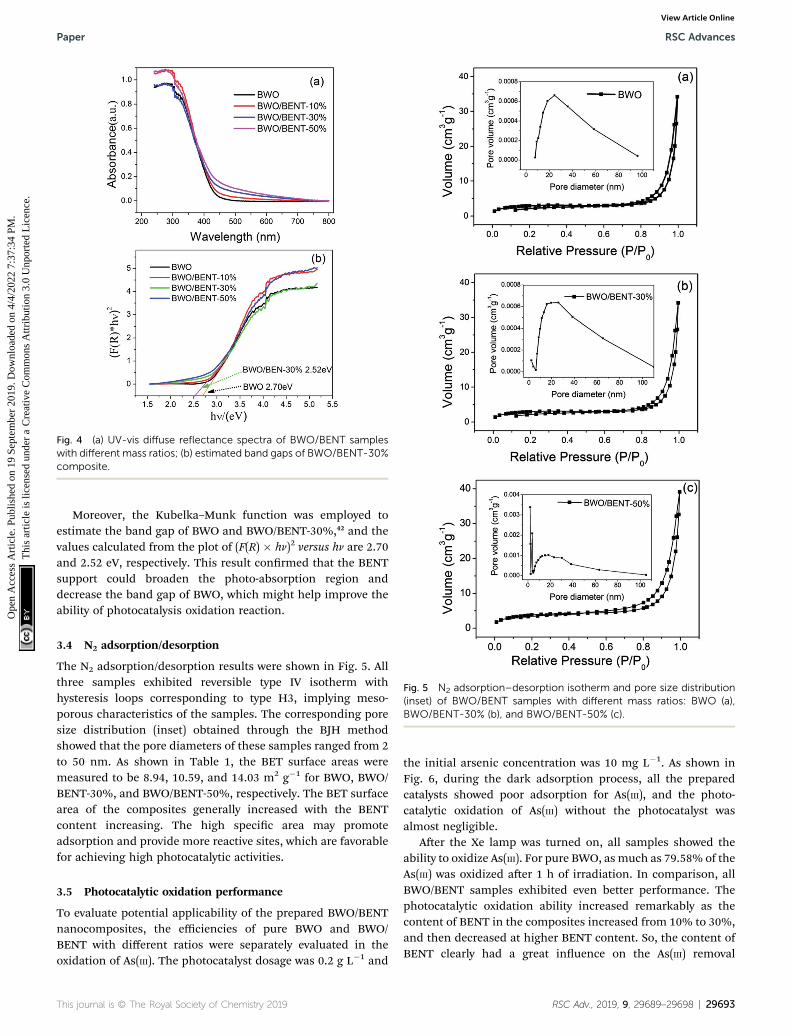
Fig. 4 (a) UV-vis diffuse reflectance spectra of BWO/BENT sampleswith different mass ratios; (b) estimated band gaps of BWO/BENT-30%composite.
Fig. 5 N2 adsorption–desorption isotherm and pore size distribution(inset) of BWO/BENT samples with different mass ratios: BWO (a),BWO/BENT-30% (b), and BWO/BENT-50% (c).
Paper RSC Advances
Ope
n A
cces
s A
rtic
le. P
ublis
hed
on 1
9 Se
ptem
ber
2019
. Dow
nloa
ded
on 4
/4/2
022
7:37
:34
PM.
Thi
s ar
ticle
is li
cens
ed u
nder
a C
reat
ive
Com
mon
s A
ttrib
utio
n 3.
0 U
npor
ted
Lic
ence
.View Article Online
Moreover, the Kubelka–Munk function was employed toestimate the band gap of BWO and BWO/BENT-30%,42 and thevalues calculated from the plot of (F(R) � hn)2 versus hn are 2.70and 2.52 eV, respectively. This result conrmed that the BENTsupport could broaden the photo-absorption region anddecrease the band gap of BWO, which might help improve theability of photocatalysis oxidation reaction.
3.4 N2 adsorption/desorption
The N2 adsorption/desorption results were shown in Fig. 5. Allthree samples exhibited reversible type IV isotherm withhysteresis loops corresponding to type H3, implying meso-porous characteristics of the samples. The corresponding poresize distribution (inset) obtained through the BJH methodshowed that the pore diameters of these samples ranged from 2to 50 nm. As shown in Table 1, the BET surface areas weremeasured to be 8.94, 10.59, and 14.03 m2 g�1 for BWO, BWO/BENT-30%, and BWO/BENT-50%, respectively. The BET surfacearea of the composites generally increased with the BENTcontent increasing. The high specic area may promoteadsorption and provide more reactive sites, which are favorablefor achieving high photocatalytic activities.
3.5 Photocatalytic oxidation performance
To evaluate potential applicability of the prepared BWO/BENTnanocomposites, the efficiencies of pure BWO and BWO/BENT with different ratios were separately evaluated in theoxidation of As(III). The photocatalyst dosage was 0.2 g L�1 and
This journal is © The Royal Society of Chemistry 2019
the initial arsenic concentration was 10 mg L�1. As shown inFig. 6, during the dark adsorption process, all the preparedcatalysts showed poor adsorption for As(III), and the photo-catalytic oxidation of As(III) without the photocatalyst wasalmost negligible.
Aer the Xe lamp was turned on, all samples showed theability to oxidize As(III). For pure BWO, as much as 79.58% of theAs(III) was oxidized aer 1 h of irradiation. In comparison, allBWO/BENT samples exhibited even better performance. Thephotocatalytic oxidation ability increased remarkably as thecontent of BENT in the composites increased from 10% to 30%,and then decreased at higher BENT content. So, the content ofBENT clearly had a great inuence on the As(III) removal
RSC Adv., 2019, 9, 29689–29698 | 29693
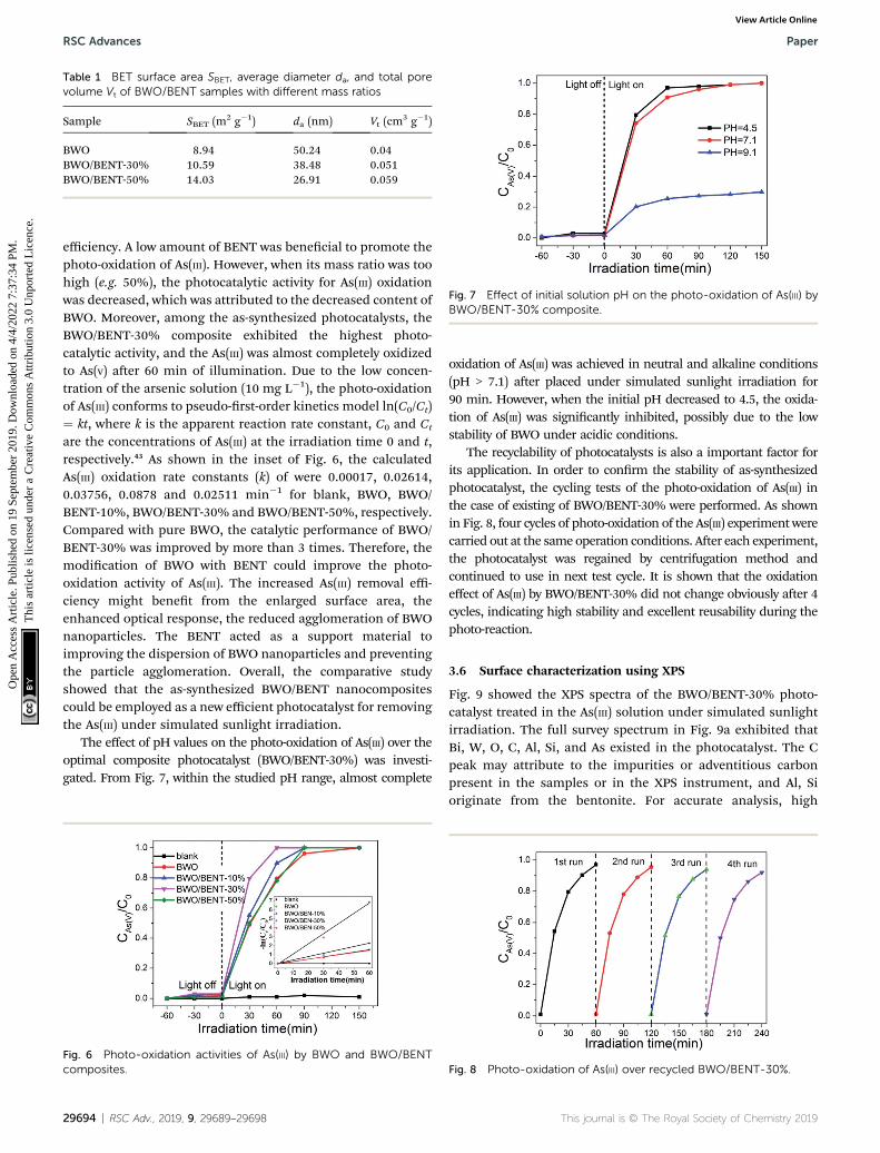
Table 1 BET surface area SBET, average diameter da, and total porevolume Vt of BWO/BENT samples with different mass ratios
Sample SBET (m2 g�1) da (nm) Vt (cm3 g�1)
BWO 8.94 50.24 0.04BWO/BENT-30% 10.59 38.48 0.051BWO/BENT-50% 14.03 26.91 0.059
Fig. 7 Effect of initial solution pH on the photo-oxidation of As(III) byBWO/BENT-30% composite.
RSC Advances Paper
Ope
n A
cces
s A
rtic
le. P
ublis
hed
on 1
9 Se
ptem
ber
2019
. Dow
nloa
ded
on 4
/4/2
022
7:37
:34
PM.
Thi
s ar
ticle
is li
cens
ed u
nder
a C
reat
ive
Com
mon
s A
ttrib
utio
n 3.
0 U
npor
ted
Lic
ence
.View Article Online
efficiency. A low amount of BENT was benecial to promote thephoto-oxidation of As(III). However, when its mass ratio was toohigh (e.g. 50%), the photocatalytic activity for As(III) oxidationwas decreased, which was attributed to the decreased content ofBWO. Moreover, among the as-synthesized photocatalysts, theBWO/BENT-30% composite exhibited the highest photo-catalytic activity, and the As(III) was almost completely oxidizedto As(V) aer 60 min of illumination. Due to the low concen-tration of the arsenic solution (10 mg L�1), the photo-oxidationof As(III) conforms to pseudo-rst-order kinetics model ln(C0/Ct)¼ kt, where k is the apparent reaction rate constant, C0 and Ct
are the concentrations of As(III) at the irradiation time 0 and t,respectively.43 As shown in the inset of Fig. 6, the calculatedAs(III) oxidation rate constants (k) of were 0.00017, 0.02614,0.03756, 0.0878 and 0.02511 min�1 for blank, BWO, BWO/BENT-10%, BWO/BENT-30% and BWO/BENT-50%, respectively.Compared with pure BWO, the catalytic performance of BWO/BENT-30% was improved by more than 3 times. Therefore, themodication of BWO with BENT could improve the photo-oxidation activity of As(III). The increased As(III) removal effi-ciency might benet from the enlarged surface area, theenhanced optical response, the reduced agglomeration of BWOnanoparticles. The BENT acted as a support material toimproving the dispersion of BWO nanoparticles and preventingthe particle agglomeration. Overall, the comparative studyshowed that the as-synthesized BWO/BENT nanocompositescould be employed as a new efficient photocatalyst for removingthe As(III) under simulated sunlight irradiation.
The effect of pH values on the photo-oxidation of As(III) over theoptimal composite photocatalyst (BWO/BENT-30%) was investi-gated. From Fig. 7, within the studied pH range, almost complete
Fig. 6 Photo-oxidation activities of As(III) by BWO and BWO/BENTcomposites.
29694 | RSC Adv., 2019, 9, 29689–29698
oxidation of As(III) was achieved in neutral and alkaline conditions(pH > 7.1) aer placed under simulated sunlight irradiation for90 min. However, when the initial pH decreased to 4.5, the oxida-tion of As(III) was signicantly inhibited, possibly due to the lowstability of BWO under acidic conditions.
The recyclability of photocatalysts is also a important factor forits application. In order to conrm the stability of as-synthesizedphotocatalyst, the cycling tests of the photo-oxidation of As(III) inthe case of existing of BWO/BENT-30% were performed. As shownin Fig. 8, four cycles of photo-oxidation of the As(III) experiment werecarried out at the same operation conditions. Aer each experiment,the photocatalyst was regained by centrifugation method andcontinued to use in next test cycle. It is shown that the oxidationeffect of As(III) by BWO/BENT-30% did not change obviously aer 4cycles, indicating high stability and excellent reusability during thephoto-reaction.
3.6 Surface characterization using XPS
Fig. 9 showed the XPS spectra of the BWO/BENT-30% photo-catalyst treated in the As(III) solution under simulated sunlightirradiation. The full survey spectrum in Fig. 9a exhibited thatBi, W, O, C, Al, Si, and As existed in the photocatalyst. The Cpeak may attribute to the impurities or adventitious carbonpresent in the samples or in the XPS instrument, and Al, Sioriginate from the bentonite. For accurate analysis, high
Fig. 8 Photo-oxidation of As(III) over recycled BWO/BENT-30%.
This journal is © The Royal Society of Chemistry 2019

Paper RSC Advances
Ope
n A
cces
s A
rtic
le. P
ublis
hed
on 1
9 Se
ptem
ber
2019
. Dow
nloa
ded
on 4
/4/2
022
7:37
:34
PM.
Thi
s ar
ticle
is li
cens
ed u
nder
a C
reat
ive
Com
mon
s A
ttrib
utio
n 3.
0 U
npor
ted
Lic
ence
.View Article Online
resolution spectrum of the Bi 4f, W 4f, O 1s, C 1s, As 3d were alsoprovided. In Fig. 9b, the binding energy at 164.4 eV and 159.1 eVcan be assigned to Bi 4f7/2 and Bi 4f5/2, respectively, indicatinga Bi3+ chemical state in the composite.44 TheW 4f XPS spectra ofthe sample was shown in Fig. 9c, exhibiting W 4f7/2 and W 4f5/2peaks at 35.5 and 37.6 eV, corresponding toW6+ species.45 The O1s spectra of the samples (Fig. 9d) present three peaks, corre-sponding to the lattice oxygen in Bi–O (529.7 eV), W–O (531.2eV), and surface adsorbed oxygen (532.6 eV).46 The As 3d XPS
Fig. 9 XPS spectra of BWO/BENT-30%: (a) survey, (b) Bi 4f, (c) W 4f, (d)
This journal is © The Royal Society of Chemistry 2019
spectra was shown in Fig. 9e, the peak at 45.6 eV can be ascribedto As(V).47 However, the peak at 45.6 eV was very weak, sug-gesting that only a very small amount of arsenic was adsorbedon the photocatalyst, which is coincident with the photo-catalytic experiment results.
3.7 PL and photocurrent analysis
Fig. 10 shows the measured surface photocurrents under Xelamp illumination. For pure BWO, the photocurrent intensity
O 1s, (e) C 1s, and (f) As 3d.
RSC Adv., 2019, 9, 29689–29698 | 29695

Fig. 10 Periodic on/off photocurrent responses for BWO and BWO/BENT composites.
RSC Advances Paper
Ope
n A
cces
s A
rtic
le. P
ublis
hed
on 1
9 Se
ptem
ber
2019
. Dow
nloa
ded
on 4
/4/2
022
7:37
:34
PM.
Thi
s ar
ticle
is li
cens
ed u
nder
a C
reat
ive
Com
mon
s A
ttrib
utio
n 3.
0 U
npor
ted
Lic
ence
.View Article Online
decreases with irradiation time, this experimental phenomenonis similar to previous research.48,49 The reason may be due to thefact that photo-generated electrons in the inner layer of Bi2WO6
need to overcome a long migration distance to reach thesurface, and electrons can accumulate and recombine withholes during the irradiation time.50 However, the photocurrentof BWO/BENT-30% kept constant with time and was higherthan those of pure BWO and BWO/BENT-50%. This may be dueto that the agglomeration of BWO nanoparticles is suppressedthrough introduction of appropriate amount of BENT, whichhelps to form monolayer BWO and improve the electron–holepair separation.
Photoluminescence (PL) is an effective method to investigateseparation effect of electrons and holes produced over photo-catalysts. Generally, a higher PL intensity indicates fasterrecombination of the charge carriers, i.e., a lower photocatalyticactivity. Fig. 11 presents the PL spectra of BWO and BWO/BENT-30% composite obtained at an excitation wavelength of 290 nm.The PL intensity of BWO/BENT-30% composite was much lowerthan that of pure BWO, indicating a reduced electron–holerecombination rate due to the introduction of BENT. Thisimproved separation performance may be caused by thesynergistic effect of BWO and BENT. This nding is consistentwith the result of photocurrent test.
Fig. 11 PL spectra of BWO and BWO/BENT-30% composite.
29696 | RSC Adv., 2019, 9, 29689–29698
3.8 Active species identication
It is generally known that photocatalyst can be activated by lightwith suitable wavelength to generate electrons and holes, thenform free radicals such as hydroxyl radical ($OH), superoxideradical ($O2
�), and hole (h+). These free radicals have a strongcapability to effectively oxidize various pollutants.51 To verify thedominant active species in the photocatalytic oxidation processof As(III), free radical quenching experiments were conductedusing different scavengers. t-BuOH, BZQ and EDTA-2Na werechosen to scavenge the $OH, $O2
� and h+, respectively. As showin Fig. 12, when no scavenger was added, BWO/BENT-30%could oxidize nearly 100% of the arsenic within 60 min. Theaddition of t-BuOH, a $OH scavenger, did not obviously sup-pressed the As(III) oxidation. However, when BZQ or EDTA-2Nawas used, an obvious suppression in the oxidation of As(III)was observed. Therefore, both $O2
� and h+ radicals wereconrmed as the major contributors for photocatalytic oxida-tion of As(III) by BWO/BENT-30% composite under simulatedsunlight irradiation. In contrast, $OH did not directlycontribute to the oxidation of As(III) during the photocatalyticprocess.
3.9 Photocatalytic mechanism
According to the above analysis, several reasons may beresponsible for the improved photocatalytic ability of theprepared composite photocatalysts. Firstly, the absorption edgeof BWO/BENT-30% showed a slight red shi in the UV-visdiffuse reectance tests, which indicated that the compositematerial had better photocatalytic response ability and lowerband gap energy than those of the pure BWO. Second, BWO/BENT-30% exhibited a larger BET surface area, meaning thatmore active sites were available for the photo-oxidation of As(III).Third, SEM analysis showed that the BENT support can reducethe agglomeration of BWO particles, which help improve thephotocatalytic ability. Fourth, because of the electrostaticattraction between the positively charged hole and the nega-tively charged BENT, the recombination of electrons and holescould be inhibited effectively. Hence, the activity of thecomposite photocatalyst was enhanced.52 Based on the analysis
Fig. 12 Effect of the scavengers on As(III) oxidation in the presence ofBWO/BENT-30% composite.
This journal is © The Royal Society of Chemistry 2019
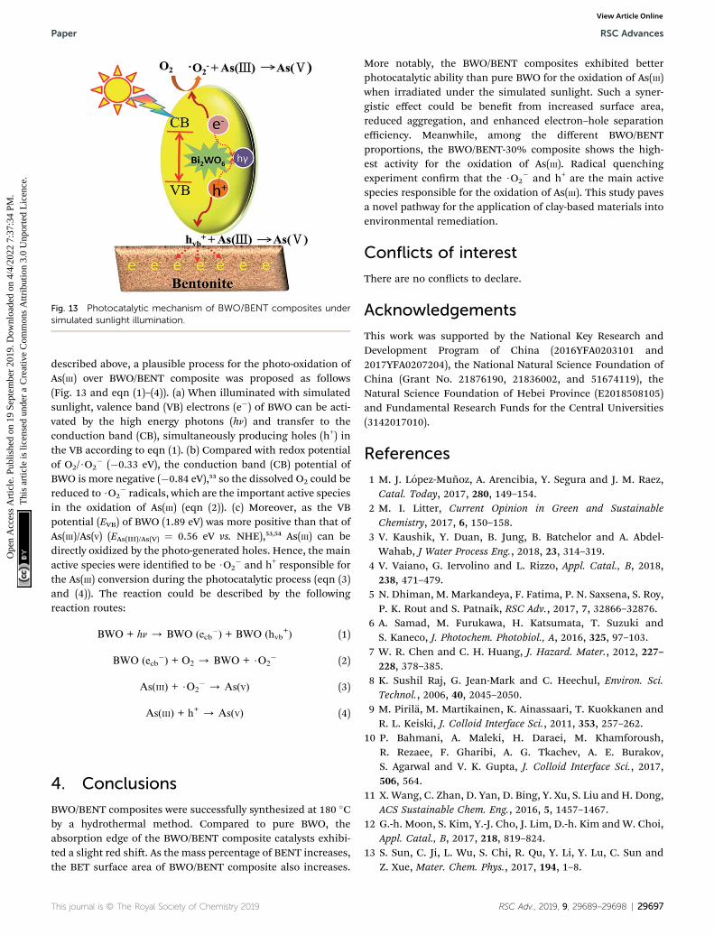
Fig. 13 Photocatalytic mechanism of BWO/BENT composites undersimulated sunlight illumination.
Paper RSC Advances
Ope
n A
cces
s A
rtic
le. P
ublis
hed
on 1
9 Se
ptem
ber
2019
. Dow
nloa
ded
on 4
/4/2
022
7:37
:34
PM.
Thi
s ar
ticle
is li
cens
ed u
nder
a C
reat
ive
Com
mon
s A
ttrib
utio
n 3.
0 U
npor
ted
Lic
ence
.View Article Online
described above, a plausible process for the photo-oxidation ofAs(III) over BWO/BENT composite was proposed as follows(Fig. 13 and eqn (1)–(4)). (a) When illuminated with simulatedsunlight, valence band (VB) electrons (e�) of BWO can be acti-vated by the high energy photons (hn) and transfer to theconduction band (CB), simultaneously producing holes (h+) inthe VB according to eqn (1). (b) Compared with redox potentialof O2/$O2
� (�0.33 eV), the conduction band (CB) potential ofBWO is more negative (�0.84 eV),53 so the dissolved O2 could bereduced to $O2
� radicals, which are the important active speciesin the oxidation of As(III) (eqn (2)). (c) Moreover, as the VBpotential (EVB) of BWO (1.89 eV) was more positive than that ofAs(III)/As(V) (EAs(III)/As(V) ¼ 0.56 eV vs. NHE),53,54 As(III) can bedirectly oxidized by the photo-generated holes. Hence, the mainactive species were identied to be $O2
� and h+ responsible forthe As(III) conversion during the photocatalytic process (eqn (3)and (4)). The reaction could be described by the followingreaction routes:
BWO + hn / BWO (ecb�) + BWO (hvb
+) (1)
BWO (ecb�) + O2 / BWO + $O2
� (2)
As(III) + $O2� / As(V) (3)
As(III) + h+ / As(V) (4)
4. Conclusions
BWO/BENT composites were successfully synthesized at 180 �Cby a hydrothermal method. Compared to pure BWO, theabsorption edge of the BWO/BENT composite catalysts exhibi-ted a slight red shi. As the mass percentage of BENT increases,the BET surface area of BWO/BENT composite also increases.
This journal is © The Royal Society of Chemistry 2019
More notably, the BWO/BENT composites exhibited betterphotocatalytic ability than pure BWO for the oxidation of As(III)when irradiated under the simulated sunlight. Such a syner-gistic effect could be benet from increased surface area,reduced aggregation, and enhanced electron–hole separationefficiency. Meanwhile, among the different BWO/BENTproportions, the BWO/BENT-30% composite shows the high-est activity for the oxidation of As(III). Radical quenchingexperiment conrm that the $O2
� and h+ are the main activespecies responsible for the oxidation of As(III). This study pavesa novel pathway for the application of clay-based materials intoenvironmental remediation.
Conflicts of interest
There are no conicts to declare.
Acknowledgements
This work was supported by the National Key Research andDevelopment Program of China (2016YFA0203101 and2017YFA0207204), the National Natural Science Foundation ofChina (Grant No. 21876190, 21836002, and 51674119), theNatural Science Foundation of Hebei Province (E2018508105)and Fundamental Research Funds for the Central Universities(3142017010).
References
1 M. J. Lopez-Munoz, A. Arencibia, Y. Segura and J. M. Raez,Catal. Today, 2017, 280, 149–154.
2 M. I. Litter, Current Opinion in Green and SustainableChemistry, 2017, 6, 150–158.
3 V. Kaushik, Y. Duan, B. Jung, B. Batchelor and A. Abdel-Wahab, J Water Process Eng., 2018, 23, 314–319.
4 V. Vaiano, G. Iervolino and L. Rizzo, Appl. Catal., B, 2018,238, 471–479.
5 N. Dhiman, M. Markandeya, F. Fatima, P. N. Saxsena, S. Roy,P. K. Rout and S. Patnaik, RSC Adv., 2017, 7, 32866–32876.
6 A. Samad, M. Furukawa, H. Katsumata, T. Suzuki andS. Kaneco, J. Photochem. Photobiol., A, 2016, 325, 97–103.
7 W. R. Chen and C. H. Huang, J. Hazard. Mater., 2012, 227–228, 378–385.
8 K. Sushil Raj, G. Jean-Mark and C. Heechul, Environ. Sci.Technol., 2006, 40, 2045–2050.
9 M. Pirila, M. Martikainen, K. Ainassaari, T. Kuokkanen andR. L. Keiski, J. Colloid Interface Sci., 2011, 353, 257–262.
10 P. Bahmani, A. Maleki, H. Daraei, M. Khamforoush,R. Rezaee, F. Gharibi, A. G. Tkachev, A. E. Burakov,S. Agarwal and V. K. Gupta, J. Colloid Interface Sci., 2017,506, 564.
11 X. Wang, C. Zhan, D. Yan, D. Bing, Y. Xu, S. Liu and H. Dong,ACS Sustainable Chem. Eng., 2016, 5, 1457–1467.
12 G.-h. Moon, S. Kim, Y.-J. Cho, J. Lim, D.-h. Kim and W. Choi,Appl. Catal., B, 2017, 218, 819–824.
13 S. Sun, C. Ji, L. Wu, S. Chi, R. Qu, Y. Li, Y. Lu, C. Sun andZ. Xue, Mater. Chem. Phys., 2017, 194, 1–8.
RSC Adv., 2019, 9, 29689–29698 | 29697

RSC Advances Paper
Ope
n A
cces
s A
rtic
le. P
ublis
hed
on 1
9 Se
ptem
ber
2019
. Dow
nloa
ded
on 4
/4/2
022
7:37
:34
PM.
Thi
s ar
ticle
is li
cens
ed u
nder
a C
reat
ive
Com
mon
s A
ttrib
utio
n 3.
0 U
npor
ted
Lic
ence
.View Article Online
14 W. Zhang, C. Liu, L. Wang, T. Zheng, G. Ren, J. Li, J. Ma,G. Zhang, H. Song, Z. Zhang and Z. Li, Colloids Surf., A,2019, 561, 364–372.
15 W. Zhang, G. Zhang, C. Liu, J. Li, T. Zheng, J. Ma, L. Wang,J. Jiang and X. Zhai, Water Res., 2018, 147, 264–275.
16 J. G. Kim, S. M. Park, M. E. Lee, E. E. Kwon and K. Baek,Chemosphere, 2018, 212, 193–199.
17 F. Zhang, C. L. Zhang, H. Y. Peng, H. P. Cong and H. S. Qian,Part. Part. Syst. Charact., 2016, 33, 248–253.
18 J. Xu, W. Ding, F. Wu, G. Mailhot, D. Zhou and K. Hanna,Appl. Catal., B, 2016, 186, 56–61.
19 Y. Liu, S. Shen, J. Zhang, Z. Wu, W. Zhong and X. Huang,Appl. Surf. Sci., 2019, 11, 7062–7096.
20 W. Zhong, S. Shen, S. Feng, Z. Lin, Z. Wang and B. Fang,CrystEngComm, 2018, 20, 7851–7856.
21 M. S. A. Hussien and I. S. Yahia, J. Photochem. Photobiol., A,2019, 368, 210–218.
22 R. Jaiswal, N. Patel, A. Dashora, R. Fernandes, M. Yadav,R. Edla, R. S. Varma, D. C. Kothari, B. L. Ahuja andA. Miotello, Appl. Catal., B, 2016, 183, 242–253.
23 F. Zhang, X. Li, X. Sun, C. Kong, W. Xie, Z. Li and J. Liu, Appl.Surf. Sci., 2019, 487, 734–742.
24 W. Zhong, Z. Lin, S. Feng, D. Wang, S. Shen, Q. Zhang, L. Gu,Z. Wang and B. Fang, Nanoscale, 2019, 11, 4407–4413.
25 M. Umer, M. Tahir, M. U. Azam and M. M. Jaffar, Appl. Surf.Sci., 2019, 463, 747–757.
26 M. Helen Selvi, P. Reddy Vanga and M. Ashok, Optik, 2018,173, 227–234.
27 T.-h. Liu, X.-j. Chen, Y.-z. Dai, L.-l. Zhou, J. Guo and S.-s. Ai, J.Alloys Compd., 2015, 649, 244–253.
28 W. Zhong, S. Shen, M. He, D. Wang, Z. Wang, Z. Lin, W. Tuand J. Yu, Appl. Catal., B, 2019, 258, 1–7.
29 F. Wang, P. Chen, Y. Feng, Z. Xie, Y. Liu, Y. Su, Q. Zhang,Y. Wang, K. Yao, W. Lv and G. Liu, Appl. Catal., B, 2017,207, 103–113.
30 F. J. Zhang, S. F. Zhu, F. Z. Xie, J. Zhang and Z. D. Meng, Sep.Purif. Technol., 2013, 113, 1–8.
31 G. Liao, J. Fang, Q. Li, S. Li, Z. Xu and B. Fang, Nanoscale,2019, 11, 7062–7096.
32 J. Ma, J. Zou, L. Li, C. Yao, Y. Kong, B. Cui, R. Zhu and D. Li,Appl. Catal., B, 2014, 144, 36–40.
33 G. Zhang, A. Song, Y. Duan and S. Zheng, MicroporousMesoporous Mater., 2018, 255, 61–68.
29698 | RSC Adv., 2019, 9, 29689–29698
34 Z. Huang, P. Wu, B. Gong, X. Zhang, Z. Liao, P.-C. Chiang,X. Hu and L. Cui, Appl. Clay Sci., 2017, 142, 128–135.
35 Y. Guo, Y. Guo, D. Tang, Y. Liu, X. Wang, P. Li and G. Wang,J. Alloys Compd., 2019, 781, 1101–1109.
36 F. Zhou, C. Yan, T. Liang, Q. Sun and H. Wang, Chem. Eng.Sci., 2018, 183, 231–239.
37 Z. Sun, G. Yao, X. Zhang, S. Zheng and R. L. Frost, Appl. ClaySci., 2016, 129, 7–14.
38 Y. Guo, Z. Gong, P. Li, W. Zhang and B. Gao, Ceram. Int.,2016, 42, 8850–8855.
39 N. Li, B. Yang, L. Xu, G. Xu, W. Sun and S. Yu, Ceram. Int.,2016, 42, 5979–5984.
40 J. Ma, D. Huang, W. Zhang, J. Zou, Y. Kong, J. Zhu andS. Komarneni, Chemosphere, 2016, 162, 269–276.
41 H. Eslami, M. H. Ehrampoush, A. Esmaeili, A. A. Ebrahimi,M. H. Salmani, M. T. Ghaneian and H. Falahzadeh,Chemosphere, 2018, 207, 303–312.
42 O. Mehraj, N. A. Mir, B. M. Pirzada and S. Sabir, Appl. Surf.Sci., 2015, 332, 419–429.
43 Y. Chai, J. Ding, L. Wang, Q. Liu, J. Ren and W.-L. Dai, Appl.Catal., B, 2015, 179, 29–36.
44 Y. Zhou, P. Lv, W. Zhang, X. Meng, H. He, X. Zeng andX. Shen, Appl. Surf. Sci., 2018, 457, 925–932.
45 S. Jonjana, A. Phuruangrat, S. Thongtem and T. Thongtem,Mater. Lett., 2018, 216, 92–96.
46 T. Huang, Y. Li, X. Wu, K. Lv, Q. Li, M. Li, D. Du and H. Ye,Chin. J. Catal., 2018, 39, 718–727.
47 W. Zhang, G. Zhang, C. Liu, J. Li, T. Zheng, J. Ma, L. Wang,J. Jiang and X. Zhai, Water Res., 2018, 147, 264–275.
48 X. Zhang, S. Yu, Y. Liu, Q. Zhang and Y. Zhou, Appl. Surf. Sci.,2017, 396, 652–658.
49 J. Wang, L. Tang, G. Zeng, Y. Liu, Y. Zhou, Y. Deng, J. Wangand B. Peng, ACS Sustainable Chem. Eng., 2017, 5, 1062–1072.
50 Y. Zhou, Y. Zhang, M. Lin, J. Long, Z. Zhang, H. Lin, J. C. Wuand X. Wang, Nat. Commun., 2015, 6, 8340.
51 P. Li, L. Huang, Y. Li, Y. Xu, S. Huang, D. Yuan, H. Xu andH. Li, J. Phys. Chem. Solids, 2017, 107, 131–139.
52 J. Ma, Q. Liu, L. Zhu, J. Zou, K. Wang, M. Yang andS. Komarneni, Appl. Catal., B, 2016, 182, 26–32.
53 J. Cheng, S. Yi, K. Chen, W. Xi, Y. Guo, X. Zhou and R. Bai,Chin. J. Catal., 2018, 39, 810–820.
54 W. c. Wu, H. q. Feng and K. z. Wu, Tables of StandardElectrode Potentials, Science Press, Beijing, 1991.
This journal is © The Royal Society of Chemistry 2019