Embed Size (px)
Citation preview

Synplicity FPGA Synthesis
Synplify Pro TutorialSeptember 2007
Synplicity, Inc.600 West California AvenueSunnyvale, CA 94086, USA
(U.S.) +1 408 215-6000 direct(U.S.) +1 408 990-0263 fax
www.synplicity.com
®

LO
ii Synplify Pro Tutorial, September 2007
Disclaimer of WarrantySynplicity, Inc. makes no representations or warranties, either expressed or implied, by or with respect to anything in this manual, and shall not be liable for any implied warranties of merchantability or fitness for a particular purpose of for any indirect, special or consequential damages.
Copyright NoticeCopyright © 2007 Synplicity, Inc. All Rights Reserved.
Synplicity software products contain certain confidential information of Synplicity, Inc. Use of this copyright notice is precautionary and does not imply publication or disclosure. No part of this publication may be repro-duced, transmitted, transcribed, stored in a retrieval system, or translated into any language in any form by any means without the prior written permission of Synplicity, Inc. While every precaution has been taken in the preparation of this book, Synplicity, Inc. assumes no responsibility for errors or omissions. This publication and the features described herein are subject to change without notice.
TrademarksSynplicity, the Synplicity logo, “Simply Better Results”, Amplify, Behavior Extracting Synthesis Technology, Certify, HDL Analyst, Identify, SCOPE, Synplify, Synplify ASIC, and Synplify Pro are registered trademarks of Synplicity, Inc. BEST, IICE, MultiPoint, and Physical Analyst are trademarks of Synplicity, Inc. All other names mentioned herein are trademarks or regis-tered trademarks of their respective companies.
Restricted Rights LegendGovernment Users: Use, reproduction, release, modification, or disclosure of this commercial computer software, or of any related documentation of any kind, is restricted in accordance with FAR 12.212 and DFARS 227.7202, and further restricted by the Synplicity Software License Agreement. Synplicity, Inc., 600 West California Avenue, Sunnyvale, CA 94086, U. S. A.
Printed in the U.S.ASeptember 2007

Synplify Pro Tutorial, September 2007 iii
Synplicity Software License Agreement
Important! READ CAREFULLY BEFORE PROCEEDING
BY INDICATING YOUR ACCEPTANCE OF THE TERMS OF THIS AGREEMENT, YOU (“LICENSEE”) ARE REPRESENTING THAT YOU HAVE THE RIGHT AND AUTHORITY TO LEGALLY BIND YOUR-SELF OR YOUR COMPANY, AS APPLICABLE, AND CONSENTING TO BE LEGALLY BOUND BY ALL OF THE TERMS OF THIS AGREEMENT. IF YOU DO NOT AGREE TO ALL THESE TERMS DO NOT INSTALL OR USE THE SOFTWARE, AND RETURN THE SOFTWARE TO THE LOCATION OF PURCHASE FOR A REFUND. This is a legal agreement governing use of the software program provided by Synplicity, Inc. (“Synplicity”) to you (the “SOFTWARE”). The term “SOFTWARE” also includes related doc-umentation (whether in print or electronic form), any authorization keys, authorization codes, and license files, and any updates or upgrades of the SOFTWARE provided by Synplicity, but does not include certain “open source” software licensed by third party licensors and made available to you by Synplicity under the terms of such third party licensor’s license (such as software licensed under the General Public License (GPL)) (“Third Party Software”). If Licensee is a participant in the University Program or has been granted an Evaluation License or Subscription License, then some of the following terms and conditions may not apply (refer to the sections entitled, respectively, Evaluation License and Subscription License, below).
License. Synplicity grants to Licensee a non-exclusive right to install the SOFTWARE and to use or authorize use of the SOFTWARE by up to the number of nodes for which Licensee has a license and for which Licensee has the security key(s) or authorization code(s) provided by Synplicity or its agents for the purpose of creating and modifying Designs (as defined below). If Licensee has obtained the SOFTWARE under a node-locked license, then a “node” refers to a specific machine, and the SOFTWARE may be installed only on the number of “nodes” or machines authorized, must be used only on the machine(s) on which it is installed, and may be accessed only by users who are physically present at that node or machine. A node-locked license may only be used by one user at a time running one instance of the software at a time. If Licensee has obtained the SOFT-WARE under a “floating” license, then a “node” refers to a concurrent user or session, and the SOFTWARE may be used concurrently by up to the number of users or sessions indicated. All SOFTWARE must be used within the country for which the systems were licensed and at Licensee's Site (contained within a one kilome-ter radius); however, if Licensee has a floating license then remote use is permitted by employees who work at the site but are temporarily telecommuting to that same site from less than 50 miles away (for example, an employee who works at a home office on occasion), but the maximum number of concurrent sessions or nodes still applies. In addition, Synplicity grants to Licensee a non-exclusive license to copy and distribute internally the documentation portion of the SOFTWARE in support of its license to use the program portion of the SOFTWARE. For purposes of this Agreement the “Licensee’s Site” means the location of the server on which the SOFTWARE resides, or when a server is not required, the location of the client computer for which the license was issued.
LO
iv Synplify Pro Tutorial, September 2007
Evaluation License. If Licensee has obtained the SOFTWARE pursuant to an evaluation license, then, in addition to all other terms and conditions herein, the following restrictions apply: (a) the license to the SOFT-WARE terminates after 20 days (unless otherwise agreed to in writing by Synplicity); and (b) Licensee may use the SOFTWARE only for the sole purpose of internal testing and evaluation to determine whether Lic-ensee wishes to license the SOFTWARE on a commercial basis. Licensee shall not use the SOFTWARE to design any integrated circuits for production or pre-production purposes or any other commercial use includ-ing, but not limited to, for the benefit of Licensee’s customers. If Licensee breaches any of the foregoing restrictions, then Licensee shall pay to Synplicity a license fee equal to Synplicity’s perpetual list price plus maintenance for the commercial version of the SOFTWARE.
Subscription (Time-Based) License. If Licensee has obtained a Subscription License to the SOFTWARE, the, in addition to all other terms and conditions herein, the following restrictions apply: (a) Licensee is autho-rized to use the SOFTWARE only for a limited time (which time is indicated on the quotation or in the pur-chase confirmation documents); (b) Licensee’s right to use the SOFTWARE terminates on the date the subscription term expires as set forth in the quotation or the purchase confirmation documents, unless Lic-ensee has renewed the license by paying the applicable fees.
Project Based License. If Licensee has obtained a Project-Based License to the SOFTWARE, in addition to all other terms and conditions herein, the terms of Exhibit A will apply.
Copy Restrictions. This SOFTWARE is protected by United States copyright laws and international treaty provisions and Licensee may copy the SOFTWARE only as follows: (i) to directly support authorized use under the license, and (ii) in order to make a copy of the SOFTWARE for backup purposes. Copies must include all copyright and trademark notices.
Use Restrictions. This SOFTWARE is licensed to Licensee for internal use only. Licensee shall not (and shall not allow any third party to): (i) decompile, disassemble, reverse engineer or attempt to reconstruct, identify or discover any source code, underlying ideas, underlying user interface techniques or algorithms of the SOFT-WARE by any means whatever, or disclose any of the foregoing; (ii) provide, lease, lend, or use the SOFT-WARE for timesharing or service bureau purposes, on an application service provider basis, or otherwise circumvent the internal use restrictions; (iii) modify, incorporate into or with other software, or create a deriv-ative work of any part of the SOFTWARE; (iv) disclose the results of any benchmarking of the SOFTWARE, or use such results for its own competing software development activities, without the prior written permission of Synplicity; or (v) attempt to circumvent any user limits, maximum gate count limits or other license, timing or use restrictions that are built into the SOFTWARE.
Transfer Restrictions/No Assignment. The SOFTWARE may only be used under this license at the desig-nated locations and designated equipment as set forth in the license grant above, and may not be moved to other locations or equipment or otherwise transferred without the prior written consent of Synplicity. Any per-mitted transfer of the SOFTWARE will require that Licensee executes a “Software Authorization Transfer Agreement” provided by Synplicity. Further, Licensee shall not sublicense, or assign this Agreement or any of the rights or licenses granted under this Agreement, without the prior written consent of Synplicity.
Security. Licensee agrees to take all appropriate measures to safeguard the SOFTWARE and prevent unautho-rized access or use thereof. Suggested ways to accomplish this include: (i) implementation of firewalls and other security applications, (ii) use of FLEXlm options file that restricts access to the SOFTWARE to identi-
Synplify Pro Tutorial, September 2007 v
fied users; (iii) maintaining and storing license information in paper format only; (iv) changing TCP port num-bers every three (3) months; and (v) communicating to all authorized users that use of the SOFTWARE is subject to the restrictions set forth in this Agreement.
Ownership of the SOFTWARE. Synplicity retains all right, title, and interest in the SOFTWARE (including all copies), and all worldwide intellectual property rights therein. Synplicity reserves all rights not expressly granted to Licensee. This license is not a sale of the original SOFTWARE or of any copy.
Ownership of Design Techniques. “Design” means the representation of an electronic circuit or device(s), derived or created by Licensee through the use of the SOFTWARE in its various formats, including, but not limited to, equations, truth tables, schematic diagrams, textual descriptions, hardware description languages, and netlists. “Design Techniques” means the data, circuit and logic elements, libraries, algorithms, search strat-egies, rule bases, techniques and technical information incorporated in the SOFTWARE and employed in the process of creating Designs. Synplicity retains all right, title and interest in and to Design Techniques incorpo-rated in the SOFTWARE, including all intellectual property rights embodied therein, provided that to the extent any Design Techniques are included as part of or embedded within Licensee’s Designs, Synplicity grants Licensee a personal, nonexclusive, nontransferable license to reproduce the Design Techniques and dis-tribute such Design Techniques solely as incorporated into Licensee’s Designs and not on a standalone basis. Additionally, Licensee acknowledges that Synplicity has an unrestricted, royalty-free right to incorporate any Design Techniques disclosed by Licensee into its software, documentation and other products, and to subli-cense third parties to use those incorporated design techniques.
Protection of Confidential Information. “Confidential Information” means (i) the SOFTWARE, in object and source code form, and any related technology, idea, algorithm or information contained therein, including without limitation Design Techniques, and any trade secrets related to any of the foregoing; (ii) either party's product plans, Designs, costs, prices and names; non-published financial information; marketing plans; busi-ness opportunities; personnel; research; development or know-how; (iii) any information designated by the disclosing party as confidential in writing or, if disclosed orally, designated as confidential at the time of dis-closure and reduced to writing and designated as confidential in writing within thirty (30) days; and (iv) the terms and conditions of this Agreement; provided, however that “Confidential Information” will not include information that: (a) is or becomes generally known or available by publication, commercial use or otherwise through no fault of the receiving party; (b) is known and has been reduced to tangible form by the receiving party at the time of disclosure and is not subject to restriction; (c) is independently developed by the receiving party without use of the disclosing party's Confidential Information; (d) is lawfully obtained from a third party who has the right to make such disclosure; and (e) is released for publication by the disclosing party in writing.
Each party will protect the other's Confidential Information from unauthorized dissemination and use with the same degree of care that each such party uses to protect its own like information. Neither party will use the other's Confidential Information for purposes other than those necessary to directly further the purposes of this Agreement. Neither party will disclose to third parties the other's Confidential Information without the prior written consent of the other party.
Third Party Software. Licensee understands and agrees that, although provided to Licensee by Synplicity, Licensee’s use of each component library or module comprising the Third Party Software shall be governed by the relevant terms and conditions of the third party’s license agreements.
Termination. Synplicity may terminate this Agreement immediately if Licensee breaches any provision, including without limitation, failure by Licensee to implement adequate security measures as set forth above.

LO
vi Synplify Pro Tutorial, September 2007
Upon notice of termination by Synplicity, all rights granted to Licensee under this Agreement will immedi-ately terminate, and Licensee shall cease using the SOFTWARE and return or destroy all copies (and partial copies) of the SOFTWARE and documentation.
Limited Warranty and Disclaimer. Synplicity warrants that the program portion of the SOFTWARE will perform substantially in accordance with the accompanying documentation for a period of 90 days from the date of receipt. Synplicity’s entire liability and Licensee’s exclusive remedy for a breach of the preceding lim-ited warranty shall be, at Synplicity’s option, either (a) return of the license fee, or (b) providing a fix, patch, work-around, or replacement of the SOFTWARE. In either case, Licensee must return the SOFTWARE to Synplicity with a copy of the purchase receipt or similar document. Replacements are warranted for the remainder of the original warranty period or 30 days, whichever is longer. Some states/jurisdictions do not allow limitations, so the above limitation may not apply. EXCEPT AS EXPRESSLY SET FORTH ABOVE, NO OTHER WARRANTIES OR CONDITIONS, EITHER EXPRESS, IMPLIED, STATUTORY OR OTH-ERWISE, ARE MADE BY SYNPLICITY OR ITS LICENSORS WITH RESPECT TO THE SOFTWARE AND THE ACCOMPANYING DOCUMENTATION, AND SYNPLICITY EXPRESSLY DISCLAIMS ALL WARRANTIES AND CONDITIONS NOT EXPRESSLY STATED HEREIN, INCLUDING BUT NOT LIM-ITED TO THE IMPLIED WARRANTIES OR CONDITIONS OF MERCHANTABILITY, NONINFRINGE-MENT, AND FITNESS FOR A PARTICULAR PURPOSE. SYNPLICITY AND ITS LICENSORS DO NOT WARRANT THAT THE FUNCTIONS CONTAINED IN THE SOFTWARE WILL MEET LICENSEE’S REQUIREMENTS, BE UNINTERRUPTED OR ERROR FREE, OR THAT ALL DEFECTS IN THE PRO-GRAM WILL BE CORRECTED. Licensee assumes the entire risk as to the results and performance of the SOFTWARE. Some states/jurisdictions do not allow the exclusion of implied warranties, so the above exclu-sion may not apply.
Limitation of Liability. IN NO EVENT SHALL SYNPLICITY OR ITS LICENSORS OR THEIR AGENTS BE LIABLE FOR ANY INDIRECT, SPECIAL, CONSEQUENTIAL OR INCIDENTAL DAMAGES WHATSOEVER (INCLUDING, WITHOUT LIMITATION, DAMAGES FOR LOSS OF BUSINESS PROF-ITS, BUSINESS INTERRUPTIONS, LOSS OF BUSINESS INFORMATION, OR OTHER PECUNIARY LOSS) ARISING OUT OF THE USE OF OR INABILITY TO USE THE SOFTWARE, EVEN IF SYNPLIC-ITY AND/OR ITS LICENSORS HAVE BEEN ADVISED OF THE POSSIBILITY OF SUCH DAMAGES. FURTHER, IN NO EVENT SHALL SYNPLICITY’S LICENSORS BE LIABLE FOR ANY DIRECT DAM-AGES ARISING OUT OF LICENSEE’S USE OF THE SOFTWARE. IN NO EVENT WILL SYNPLICITY OR ITS LICENSORS BE LIABLE TO LICENSEE FOR DAMAGES IN AN AMOUNT GREATER THAN THE FEES PAID FOR THE USE OF THE SOFTWARE. Some states/jurisdictions do not allow the limitation or exclusion of incidental or consequential damages, so the above limitations or exclusions may not apply.
Intellectual Property Right Infringement. Synplicity will defend or, at its option, settle any claim or action brought against Licensee to the extent it is based on a third party claim that the SOFTWARE as used within the scope of this Agreement infringes or violates any US patent, copyright, trade secret or trademark of any third party, and Synplicity will indemnify and hold Licensee harmless from and against any damages, costs and fees reasonably incurred that are attributable to such claim or action; provided that Licensee provides Synplicity with (i) prompt written notification of the claim or action; (ii) sole control and authority over the defense or settlement thereof (including all negotiations); and (iii) at Synplicity’s expense, all available information, assistance and authority to settle and/or defend any such claim or action. Synplicity’s obligations under this subsection do not apply to the extent that (i) such claim or action would have been avoided but for modifica-tions of the SOFTWARE, or portions thereof, other than modifications made by Synplicity after delivery to Licensee; (ii) such claim or action would have been avoided but for the combination or use of the SOFT-WARE, or portions thereof, with other products, processes or materials not supplied or specified in writing by

Synplify Pro Tutorial, September 2007 vii
Synplicity; (iii) Licensee continues allegedly infringing activity after being notified thereof or after being informed of modifications that would have avoided the alleged infringement; or (iv) Licensee’s use of the SOFTWARE is not strictly in accordance with the terms of this Agreement. Licensee will be liable for all dam-ages, costs, expenses, settlements and attorneys’ fees related to any claim of infringement arising as a result of (i)-(iv) above.
If the SOFTWARE becomes or, in the reasonable opinion of Synplicity is likely to become, the subject of an infringement claim or action, Synplicity may, at Synplicity’s option and at no charge to Licensee, (a) obtain a license so Licensee may continue use of the SOFTWARE; (b) modify the SOFTWARE to avoid the infringe-ment; (c) replace the SOFTARE with a compatible, functionally equivalent, and non-infringing product, or (d) refund to Licensee the amount paid for the SOFTWARE, as depreciated on a straight-line 5-year basis, or such other shorter period applicable to Subscription Licenses.
THE FOREGOING PROVISIONS OF THIS SECTION STATE THE ENTIRE AND SOLE LIABILITY AND OBLIGATIONS OF SYNPLICTY, AND THE EXCLUSIVE REMEDY OF LICENSEE, WITH RESPECT TO ANY ACTUAL OR ALLEGED INFRINGEMENT OF ANY INTELLECTUAL PROPERTY RIGHTS BY THE SOFTWARE (INCLUDING DESIGN TECHNIQUES) AND DOCUMENTATION.
Export. Licensee warrants that it is not prohibited from receiving the SOFTWARE under U.S. export laws; that it is not a national of a country subject to U.S. trade sanctions; that it will not use the SOFTWARE in a location that is the subject of U.S. trade sanctions that would cover the SOFTWARE; and that to its knowledge it is not on the U.S. Department of Commerce’s table of deny orders or otherwise prohibited from obtaining goods of this sort from the United States.
Miscellaneous. This Agreement is the entire agreement between Licensee and Synplicity with respect to the license to the SOFTWARE, and supersedes any previous oral or written communications or documents (including, if you are obtaining an update, any agreement that may have been included with the initial version of the Software). This Agreement is governed by the laws of the State of California, USA excluding its con-flicts of laws principals. This Agreement will not be governed by the U. N. Convention on Contracts for the International Sale of Goods and will not be governed by any statute based on or derived from the Uniform Computer Information Transactions Act (UCITA). If any provision, or portion thereof, of this Agreement is found to be invalid or unenforceable, it will be enforced to the extent permissible and the remainder of this Agreement will remain in full force and effect. Failure to prosecute a party’s rights with respect to a default hereunder will not constitute a waiver of the right to enforce rights with respect to the same or any other breach.
Government Users. If the SOFTWARE is licensed to the United States government or any agency thereof, then the SOFTWARE and any accompanying documentation will be deemed to be “commercial computer soft-ware” and “commercial computer software documentation”, respectively, pursuant to DFAR Section 227.7202 and FAR Section 12.212, as applicable. Any use, reproduction, release, performance, display or disclosure of the SOFTWARE and accompanying documentation by the U.S. Government will be governed solely by the terms of this Agreement and are prohibited except to the extent expressly permitted by the terms of this Agree-ment.
June 2005

LO
viii Synplify Pro Tutorial, September 2007

Synplify Pro Tutorial, September 2007 ix
Contents
Introduction to the Tutorial . . . . . . . . . . . . . . . . . . . . . . . . . . . . . . . . . . . . . . . . . . . . . 2Start the Software . . . . . . . . . . . . . . . . . . . . . . . . . . . . . . . . . . . . . . . . . . . . . . . . 2Download Tutorial Files . . . . . . . . . . . . . . . . . . . . . . . . . . . . . . . . . . . . . . . . . . . . 4Tutorial Directory Structure . . . . . . . . . . . . . . . . . . . . . . . . . . . . . . . . . . . . . . . . . 5Synthesis Files . . . . . . . . . . . . . . . . . . . . . . . . . . . . . . . . . . . . . . . . . . . . . . . . . . . 6See Also . . . . . . . . . . . . . . . . . . . . . . . . . . . . . . . . . . . . . . . . . . . . . . . . . . . . . . . . 8
Tutorial Design Flow . . . . . . . . . . . . . . . . . . . . . . . . . . . . . . . . . . . . . . . . . . . . . . . . . . 9
Create Project . . . . . . . . . . . . . . . . . . . . . . . . . . . . . . . . . . . . . . . . . . . . . . . . . . . . . . 10Setup Project and Add Design Files . . . . . . . . . . . . . . . . . . . . . . . . . . . . . . . . . 10Compile Design and Check Log File . . . . . . . . . . . . . . . . . . . . . . . . . . . . . . . . . 16Additional Analysis after Compile . . . . . . . . . . . . . . . . . . . . . . . . . . . . . . . . . . . . 18
Setup Implementation for Synthesis . . . . . . . . . . . . . . . . . . . . . . . . . . . . . . . . . . . . . 19Set Constraints . . . . . . . . . . . . . . . . . . . . . . . . . . . . . . . . . . . . . . . . . . . . . . . . . . 19Set Device Options . . . . . . . . . . . . . . . . . . . . . . . . . . . . . . . . . . . . . . . . . . . . . . 23
Analyze Logic Synthesis Results . . . . . . . . . . . . . . . . . . . . . . . . . . . . . . . . . . . . . . . 29Examine the Technology View . . . . . . . . . . . . . . . . . . . . . . . . . . . . . . . . . . . . . . 29Check Timing . . . . . . . . . . . . . . . . . . . . . . . . . . . . . . . . . . . . . . . . . . . . . . . . . . . 31Analyze Critical Paths in the Technology View . . . . . . . . . . . . . . . . . . . . . . . . . 34Set Additional Constraint and Resynthesize . . . . . . . . . . . . . . . . . . . . . . . . . . . 36Check Results . . . . . . . . . . . . . . . . . . . . . . . . . . . . . . . . . . . . . . . . . . . . . . . . . . 38
Appendix A: Early Analysis (Compile Phase) . . . . . . . . . . . . . . . . . . . . . . . . . . . . . 39Analyze Compile Results (RTL) and Navigate Hierarchy . . . . . . . . . . . . . . . . . 39Find and Crossprobe . . . . . . . . . . . . . . . . . . . . . . . . . . . . . . . . . . . . . . . . . . . . . 44Filter, Expand, Hide, and Dissolve . . . . . . . . . . . . . . . . . . . . . . . . . . . . . . . . . . . 51

LO
x Synplify Pro Tutorial, September 2007

Synplify Pro Tutorial, September 2007 1
Synplify Pro Tutorial
The tutorial shows you how to use the Synplify Pro software in the FPGA logic design process. Information is organized into these topics:
• Introduction to the Tutorial on page 2
• Tutorial Design Flow on page 9
• Create Project on page 10
• Setup Implementation for Synthesis on page 19
• Run Logic Synthesis on page 28
• Analyze Logic Synthesis Results on page 29
• Improve Results on page 36
• Appendix A: Early Analysis (Compile Phase) on page 39

LO
Synplify Pro Tutorial Introduction to the Tutorial
2 Synplify Pro Tutorial, September 2007
Introduction to the TutorialThe tutorial is designed to walk you through the Synplify Pro design flow using some typical tasks and familiarize you with the user interface.
The tutorial design is an 8-bit micro controller. After completing the tutorial, you will be familiar with the tool and able to apply the knowledge you gained to your own, more complicated designs.
The tutorial assumes that you have
• Installed the software correctly and obtained the necessary licenses.
• Basic understanding of logic synthesis using the Synplicity FPGA tools.
The remaining sections include the following topics:
• Start the Software on page 2.
• Download Tutorial Files on page 4.
• Tutorial Directory Structure on page 5.
• Synthesis Files on page 6
• See Also on page 8
Start the SoftwareYou can start the software and run the tutorial from a Windows, Linux, or Solaris workstation.
1. On Windows , choose the current release of the software from: Start->Programs->Synplicity->Synplify Pro 8.8.0.4.
If you use any other version of the software, results may not exactly match the results in the tutorial, although you can still follow the general methodology described in this document.
2. On Solaris or Linux, type this at the command line:
synplify_pro
The command starts the synthesis tool. If you have run the software before, the window displays the previous project.

Introduction to the Tutorial Synplify Pro Tutorial
Synplify Pro Tutorial, September 2007 3
If you do not see the Tcl window and Log Watch window, select View -> Tcl Window and View -> Log Watch Window. For your information, you can access commands in different ways: through the main menu, popup menus, keyboard shortcuts, and icons. The tutorial uses different methods to access the commands. For more information about the interface, see the Synplicity FPGA Synthesis Reference Manual.
MenusToolbars
Implementation Results View
Tcl Window Project View Log Watch Window

LO
Synplify Pro Tutorial Introduction to the Tutorial
4 Synplify Pro Tutorial, September 2007
Download Tutorial FilesYou can download the tutorial design files and the tutorial instructions from the Synplicity Technical Resource Center.
1. To access the Synplicity Technical Resource Center, either:
– Select Web->Go to Resource Center from the Project menu. Then, select Tutorials from the left side menu.
– Type the following in an internet browser:
http://trc.synplicity.com/tutorials/index.html
2. Select the applicable release for the tutorial and download the platform-specific version of the design files.
3. Unzip the tutorial files.
– On Windows, use Winzip to extract the tutorial files.
– On Solaris or Linux, type the following at the command line:
gunzip tutorial.tar.gz
Then, to extract the tutorial files, type the following at the command line:
tar -xvf tutorial.tar
– Open or print the tutorial instructions (tutorial.pdf) from the TRC when you are ready to begin the tutorial.
4. Copy the tutorial directory to your working area. Keep the directory structure, because the tutorial is based on this structure. Refer to Tutorial Directory Structure on page 5. When you work on your own designs, you can set up the structure as you want.
5. Make sure you have read and write privileges for the tutorial files.

Introduction to the Tutorial Synplify Pro Tutorial
Synplify Pro Tutorial, September 2007 5
Tutorial Directory StructureThe input files for this tutorial are provided in the Synplify Pro tutorial directory after you download files from the Synplicity Technical Resource Center and setup your project. The project and contraint files will be created using this tutorial. However, if you prefer you can use these files provided with the design as well.
Note: This directory structure is used for the tutorial because it reflects the way the tool structures the files in the Project view. However, when you run the Synplify Pro software on your own, you can create whatever directory structure works best for your design.
Figure 1: Synplify Pro FPGA tutorial Directory Structure
For descriptions of these files see Input Files on page 6.
Figure 2 shows the directory structure for the implementation results files, using the default implementation name rev_1. You specify the location of the results directory when you set implementation options for your project.
tutorial
tutorial.prjVerilogVHDLConstraint
tutorial.sdc const_pkg.vhdins_rom.vhd
alu.vdata_mux.veight_bit_uc.v*ins_decode.vio.v
pc.vreg_file.vspcl_regs.v
* This is the top-level module
mult.v
state_mc.v

LO
Synplify Pro Tutorial Introduction to the Tutorial
6 Synplify Pro Tutorial, September 2007
After you complete this exercise, the results directory typically contains the file types shown below.
Figure 2: Results Directory Structure
For descriptions of these files, see Output Files on page 7.
Synthesis FilesThis section briefly describes the files required to run synthesis and the files generated during synthesis that are output to the user-specified implementa-tion results directory.
Input FilesHere is a brief description of the input files:
• .v/.vhd—contains the HDL source files. The HDL source files can also contain a mixture of VHDL and Verilog source files. eight_bit_uc.v is the top-level module.
• constraint/tutorial.sdc—user-specified constraint file, contains the timing constraints
The contraint file will be created using this tutorial. However, you can use the .sdc file provided with the design, if preferred.
• tutorial.prj—tutorial project file, contains all the information required to complete a design. This file contains references to source files, and specifications for the target device.
rev_1
tutorial
eight_bit_uc.edfeight_bit_uc.ncfeight_bit_uc.htmeight_bit_uc.srmeight_bit_uc.srreight_bit_uc.srs

Introduction to the Tutorial Synplify Pro Tutorial
Synplify Pro Tutorial, September 2007 7
The project file will be created using this tutorial. However, you can use the .prj file provided with the design, if preferred.
Output FilesHere is a brief description of the files that are typically output to the Implemen-tation Results directory:
• .edf—Xilinx design netlist in the format of the supported target place-and-route tool
• .htm—HTML format of the log file containing the synthesis results. See the .srr file below for a description of its contents.
• .ncf—Xilinx netlist constraint file; contains all of the constraints for the design
• .srm—output by the mapper stage of the process, contains the actual technology-specific mapped design. This is the representation displayed through the technology view in HDL Analyst.
• .srr—text format of the log file containing the synthesis results. The project_name.srr file contains all warnings and errors encountered during synthesis as well as performance information such as clock frequency, critical paths and run times. There is also information on area, cell usage and FSM extraction. To view this file, click on the View Log button in the Project view.
• .srs—output by the compiler stage of the process, contains the RTL level (schematic) view of the design. This is the representation displayed through the RTL view in HDL Analyst.
Note: You can delete or rename the tutorial.prj and the tutorial.sdc files in this directory if you want to create your own as part of the tutorial exercises.

LO
Synplify Pro Tutorial Introduction to the Tutorial
8 Synplify Pro Tutorial, September 2007
See AlsoThe tutorial does not cover all the possible tasks you could do. For additional information, refer to the following sources:
For information about... See the...
Installation Installation instructions
Common tasks not covered in the tutorial
Synplicity FPGA Synthesis User Guide
Advanced techniques Synplicity FPGA Synthesis User Guide
User interface descriptions Synplicity FPGA Synthesis Reference Manual
Commands and syntax Synplicity FPGA Synthesis Reference Manual

Tutorial Design Flow Synplify Pro Tutorial
Synplify Pro Tutorial, September 2007 9
Tutorial Design FlowThis flow diagram graphically illustrates the procedures in this tutorial:
The remaining sections describe how to complete the tasks for this flow.
Create Project
Implement FPGA
HDL Source Files
Technology Parameters
Set Constraints
Analyze Logic Synthesis Results
Set Device Options
Xilinx Flow
Improve Results
Vendor Flow
Run Logic Synthesis

LO
Synplify Pro Tutorial Create Project
10 Synplify Pro Tutorial, September 2007
Create ProjectThe first step is to set up your project. A project is a file that defines the HDL source files, implementation files and device option settings. This section shows you how to set up a project file, handle messages, and do some typical analysis operations with the HDL Analyst tool. This project information is organized as follows:
• Setup Project and Add Design Files
• Compile Design and Check Log File
• Additional Analysis after Compile
Setup Project and Add Design FilesTo run synthesis, you need a project file. A project contains the data needed for a particular design: the source files, the name of the synthesis results file, and your device option settings. The following procedure shows you how to set up a project file.
1. In the project window, select File->Build Project to open the Select Files to Add to Project dialog box. Navigate to your source files by selecting the install_dir/tutorial directory.

Create Project Synplify Pro Tutorial
Synplify Pro Tutorial, September 2007 11
Figure 1: Select Files to Add to Project Dialog Box
2. Open the vhdl folder. Make sure Files of type field is showing either All Files (*) or VHDL Files (*.vhd).
For this exercise, add both VHDL files in the folder. Click on the <-Add All button, then click OK.

LO
Synplify Pro Tutorial Create Project
12 Synplify Pro Tutorial, September 2007
Figure 2: Add VHDL Files
– After clicking OK to add the files, you will return to the Project view.
Figure 3: Newly Created Project File
Your project window displays a newly-created project file called const_pkg (the first source file in the list) with a folder called VHDL and a directory under it called rev_1, which represents the first implementation of your design.
3. Set the source file hierarchy, if necessary.

Create Project Synplify Pro Tutorial
Synplify Pro Tutorial, September 2007 13
– If you do not see a VHDL folder under the const_pkg directory, set this preference by selecting the Options->Project View Options command and checking the View project files in folders box. This separates one kind of file from another in the Project view by putting them in separate folders.
Figure 4: Select Project View Options->View project files in folders
4. Click on the Add File button in the Project view and change to the verilog directory. Make sure Files of type field is showing either All Files (*) or Verilog Files (*.v).
5. For this exercise, add all the Verilog files in the folder. Click on the <-Add All button, then click OK.

LO
Synplify Pro Tutorial Create Project
14 Synplify Pro Tutorial, September 2007
Figure 5: Add Verilog Files
A virtual design directory structure is created in the Project view. Figure 7 shows the UI after adding the design files.
– Click on the plus sign next to the Verilog folder to see a list of the Verilog source files that you added for the project.
– Drag the top-level Verilog file to the last position in the list of files to manually rearrange them.
– The project window reflects your changes. Make sure that the top-level file (eight_bit_uc.v) is the last in the list of files in the Project window. The order of the remaining files does not matter.

Create Project Synplify Pro Tutorial
Synplify Pro Tutorial, September 2007 15
Figure 6: Verilog Files Before and After Arranging
However, since we are using a mixed-language design for this exercise, and the top-level module is Verilog, specify the top-level module in the Verilog panel of the Implementation Options dialog box.
6. Click on the Impl Options button and click on the Verilog tab. See Set Device Options on page 23 for more information.
Top-level file last
Project name
Before Arranging Verilog Files After Arranging Verilog Files

LO
Synplify Pro Tutorial Create Project
16 Synplify Pro Tutorial, September 2007
7. Then select File->Save As, move up a directory level and type tutorial for the name of the project, and click Save.
Compile Design and Check Log FileFor the purposes of this tutorial, you compile and check the log file as separate steps. Normally, compilation is part of synthesis when you press Run.
1. Press F7 or select Run -> Compile Only.
The software optimizes the logic for your design using technology-independent operations, and checks for syntax and hardware-related synthesis errors. When it has compiled, you see the following changes in the Project view:
2. Review the messages in the Message viewer.
– Click the Messages tab in the Tcl window. Enlarge the message window if needed, or drag it out of its docked location to get a full-size window. You see all the messages listed. Notes have an ‘n’ icon, and warnings have a yellow triangle with an exclamation mark.
F7
RTL icon now selectable
Note: Exclamation marks indicate files with warnings.

Create Project Synplify Pro Tutorial
Synplify Pro Tutorial, September 2007 17
– Locate the Found RAM mem_regfile, depth=32, width=8 entry and click the ID number CL134.
The online messages help reports that the compiler detects a RAM and indicates the depth and width of the RAM. The compiler detects high-level operators such as RAMs, so that the right resources are used to implement these operators during the mapping phase.
3. If you prefer, review the messages in the Log file. You can perform any of the following tasks:
– Enable the View Log File in HTML option under Options->Project View Options. Click View Log to open the log file and click Compiler Report in the left panel. Scroll through the log file messages on the right.
– Double-click on the log file in the Project view and press Ctrl-f to open the Find dialog box. Enter @N as the search criteria, and click Find Next. The pointer moves to the first note in the log file. Click Find Next again until you find message number (CL134).
Review all messages and then click Cancel in the Find dialog box. If needed, you can also enter the following search criteria: @I for informational messages and @W for warnings.
– Single click the message number (CD134) in the HTML Log file, or double-click the message number in the text-based Log file to open an online help page with information about the message.

LO
Synplify Pro Tutorial Create Project
18 Synplify Pro Tutorial, September 2007
4. Review all messages. For this exercise, all messages are valid.
Additional Analysis after CompileOnce you have a compiled design, you can perform additional analysis before completely synthesizing the design. These include:
• Viewing an RTL schematic of the design
• Crossprobing between the schematic, source code and log file
• Using Object Find in the RTL view
• Filtering and expanding the schematic
See Appendix A: Early Analysis (Compile Phase) on page 39 for details.

Setup Implementation for Synthesis Synplify Pro Tutorial
Synplify Pro Tutorial, September 2007 19
Setup Implementation for SynthesisThis synthesis flow for Xilinx uses the Virtex-4 technology. The following sections discuss these topics:
• Set Constraints, next
• Set Device Options on page 23
• Run Logic Synthesis on page 28
• Analyze Logic Synthesis Results on page 29
If you do not use Xilinx technology, you can follow along with the tutorial using device options specific to your vendor. However, for the following section of this tutorial, make sure that the Xilinx Virtex-4 technology is selected on the Implementation Options dialog box of the Device tab. See Set Device Options on page 23.
Set ConstraintsDesign constraints are optional, but most designers use them to define frequency goals and describe the environment for the design. For designs without aggressive timing goals, you can just set the clock frequency.
You can set constraints in a text file that you can create with any text editor, but it is easier to use the SCOPE (Synthesis Constraint Optimization Environ-ment) interface. The SCOPE interface consists of a spreadsheet where you enter constraints.
The tutorial design uses basic constraints, which you enter as follows:
1. Start the SCOPE interface in the open project window by doing one of the following:
– Click the New Constraint file (SCOPE) icon in the toolbar. ( )
– Select File->New, choose Constraint file (SCOPE) in the dialog box, specify the file name (tutorial.sdc) and click OK.
2. Click OK on the Initialize Constraints tab in the Create a New SCOPE File dialog box.

LO
Synplify Pro Tutorial Setup Implementation for Synthesis
20 Synplify Pro Tutorial, September 2007
The SCOPE window opens, with the most common constraints, clock frequency and input/output delays initialized. The window consists of a spreadsheet interface with tabs for different kinds of constraints.
3. Set a clock frequency constraint as follows:
– Select the Clocks tab at the bottom of the SCOPE window, if it is not already selected.
– Select the check box in the Enabled column to enable the clock constraint.

Setup Implementation for Synthesis Synplify Pro Tutorial
Synplify Pro Tutorial, September 2007 21
Figure 7: Set Clock Frequency to 125
This design has only one clock, so setting the clock frequency is the same as setting a global frequency from the Project view. When you press Enter, the software automatically sets the clock period and assigns the clock to the default clock group.
4. For this exercise, set a false path constraint. Perform the following:
– Select the False Paths tab at the bottom of the SCOPE window.
– Select the check box in the Enabled column to enable the false path constraint.
– In the From field of SCOPE, select i:special_regs.status{7:0] from the drop-down menu.
5. Also for this exercise, you will set some attribute constraints. Perform the following tasks:
– Select the Attributes tab at the bottom of the SCOPE window.
– Select the check box in the Enabled column to enable the attributes specified below.

LO
Synplify Pro Tutorial Setup Implementation for Synthesis
22 Synplify Pro Tutorial, September 2007
– From the Attributes field, select syn_forward_io_constraints from the drop-down menu and press Enter. Leave the default setting for all other fields of this attribute.
– From the Attributes field, select the syn_dspstyle attribute from the drop-down menu. Then, select logic from the drop-down menu in the Value field.
– From the Attributes field, select the syn_ramstyle attribute from the drop-down menu. Then, select registers from the drop-down menu in the Value field.
6. Click the Save ( ) icon or select File->Save and save the file as tutorial.sdc.
7. Click Yes in the dialog box that asks you if you want to add the file to your project and close the SCOPE window.
You should now have the following files in the project:
– A Verilog folder that contains the source files
– A VHDL folder that contains the source files
– A Constraint folder with the constraint file (tutorial.sdc)
– An implementation folder (rev_1)
8. Close the SCOPE file.

Setup Implementation for Synthesis Synplify Pro Tutorial
Synplify Pro Tutorial, September 2007 23
Set Device OptionsThe options you set for a project revision (implementation) determine the optimization settings and inputs such as the device technology, constraint files, and output directory for the synthesis run.
1. Make sure rev_1 is the current implementation (indicated by a green arrow). You can bring up the Options for Implementation dialog box in the Project view with one of the following methods:
– Impl Options button
– Select Project->Implementation Options
– New Impl button (for creating a new implementation only)
The Options for Implementation dialog box lists the implementation (rev_1) at the top.
2. This dialog box has many tabs, and opens with the Device tab displayed. For this exercise:
– Technology should already be set to Xilinx Virtex4.
– Use the following technology defaults of: Part XC4VLX15, Speed -10, and Package SF363.
– Do not change the default settings for the Device Mapping Options.

LO
Synplify Pro Tutorial Setup Implementation for Synthesis
24 Synplify Pro Tutorial, September 2007
3. Click on the Options tab. For this exercise, do not change the default optimization switches for:
– FSM Compiler
– Resource Sharing
– Pipelining
4. Click on the Constraints tab. Make sure the constraint file (tutorial.sdc) is checked.

Setup Implementation for Synthesis Synplify Pro Tutorial
Synplify Pro Tutorial, September 2007 25
5. Click on the Implementation Results tab. Make sure that:
– Implementation Name, Results Directory, and Result File Name fields automatically get filled in.
– Result Format should be edif.
– Write Vendor Constraint File is enabled.
– Write Verification Interface Format (VIF) File is enabled.

LO
Synplify Pro Tutorial Setup Implementation for Synthesis
26 Synplify Pro Tutorial, September 2007
6. Click on the Timing Report tab. Set Number of Critical Paths to 25.
This option determines the number of critical paths reported in the timing report generated after synthesis.
7. Click on the Place and Route tab. You can ignore this option for this exercise, since placement and routing will not be run.
8. Click on the Verilog tab. For this exercise:
– Check that the Top Level Module is specified as eight_bit_uc.
– Leave the default for Verilog 2001 enabled.
– Leave the default for Push Tristates enabled.

Setup Implementation for Synthesis Synplify Pro Tutorial
Synplify Pro Tutorial, September 2007 27
9. Click on the VHDL tab. For this exercise:
– Select default from the Default Enum Encoding drop-down menu for the top-level entity (eight_bit_uc).
– Leave the default setting for Push Tristates enabled.
10. Click OK to save the implementation options for rev_1.

LO
Synplify Pro Tutorial Run Logic Synthesis
28 Synplify Pro Tutorial, September 2007
The exercise in this section presents a summary of the implementation options as they relate to the tutorial exercise. For more details on setting implementation options, see the Constraints, Attributes, and Options chapter of the Synplicity FPGA Synthesis User Guide.
Run Logic SynthesisAfter you have set up your project with source files, implementation settings, and an optional constraint file, synthesize your design. To do this:
1. Click the Run button to start synthesis.
The software goes through two synthesis phases, compilation and mapping, and it reflects these stages in large red letters in the status area.
– Compilation is the creation of a technology-independent boolean structure, and mapping is the technology-specific implementation and optimization of the boolean structure.
– You can see the results of compilation in the RTL view. Mapping results are displayed in the Technology view, which is described in more detail in subsequent sections.
2. When synthesis is complete, the software usually displays this message:
Note that the Implementation Results view lists the files that are gener-ated as a result of synthesis.

Analyze Logic Synthesis Results Synplify Pro Tutorial
Synplify Pro Tutorial, September 2007 29
Analyze Logic Synthesis ResultsAfter you have run synthesis, you can analyze the results. This section shows you how to do the following:
• Examine the Technology View, next
• Check Timing on page 31
• Analyze Critical Paths in the Technology View on page 34
Examine the Technology ViewYou can graphically check the synthesis results in the Technology view.
1. To see the graphical results of your run, click the ( ) icon on the menu bar to open the Technology view.
The Technology view contains a schematic of the design after technology mapping with base cells that are directly mapped to the target technology.
2. Examine one of the technology-specific components as described below. If you are not using the version of software for which this tutorial was written, your design may be implemented with different components because of ongoing optimizations to the technology and the software.
– To reduce congestion in the schematic, select Options->HDL Analyst Options and disable Show cell interior on the General tab if it is on. You can also disable the display of symbol and pin names on the Text tab. Click OK.
– In the Hierarchy Browser on the left side of the Technology view, expand Instances and then expand one of the modules. In the following example, we chose REGS (REGS_FILE).

LO
Synplify Pro Tutorial Analyze Logic Synthesis Results
30 Synplify Pro Tutorial, September 2007
– Next expand Primitives and select a primitive instance. The instance selected is highlighted in red on the schematic. When you have multiple sheets, the Technology view automatically moves to the sheet with the selected component.
Note: Small sheet size is a preference you can set with Options->HDL Analyst Options->Sheet Size.
– Filter the selected component. To filter, click F12, the Filter icon, or click the right mouse button and select Filter Schematic. You see just the object selected.
– To see details of this object, select Options->HDL Analyst Options and enable Show symbol name and Show pin name on the Text tab, and Show cell interior on the General tab. Click OK. You see the interior of the cell. Roll the cursor over the pins to see the pin names. You also see any properties attached to the pins, like fanout.
F12

Analyze Logic Synthesis Results Synplify Pro Tutorial
Synplify Pro Tutorial, September 2007 31
– Deselect the component by clicking in an empty area of the schematic.
– Use the techniques described in Additional Analysis after Compile on page 18, Find and Crossprobe on page 44, and Filter, Expand, Hide, and Dissolve on page 51 to examine how the design was implemented for this technology.
– When finished, close the Technology view window.
Check TimingYou can check timing results in the log file and in the Log Watch window.
Using the Log Watch WindowIn the tool, the Log Watch Window is a quick way to view just the critical timing.
1. Check the timing parameters in the Log Watch window:
– If you do not already have it open, select View -> Log Watch Window to open a window where you can quickly see the critical timing information in a tabular format.
– Position the cursor in the first cell in the Log Parameter column, and hold down the left mouse button.
Pin names
Pin properties

LO
Synplify Pro Tutorial Analyze Logic Synthesis Results
32 Synplify Pro Tutorial, September 2007
– Select Worst Slack from the drop-down list. The software displays the corresponding value.
– Use the same method to set clock - Estimated Frequency and clock - Requested Frequency in subsequent cells. You can see that the design does not meet timing because it has a negative slack value. Positive or 0 slack times indicate that you have met or are within the timing constraint. Close the Log Watch window.
The following figure shows the values in the Log Watch window after the run. If you are using a different release of the software, the values you get when you run the tutorial might vary slightly, because of ongoing optimizations within the synthesis tool.
Using the Log FileThe log file is available in text format, as well as, the HTML-based viewer for the Synplify Pro tool. To enable the HTML version of the log file, select Options->Project View Options->View log file in HTML.
To see detailed information about the critical paths, open the log file (eight_bit_uc.srr) by clicking the View Log button. You see a window with the log file.
• In the text-based log file window, scroll down to the Performance Summary section to see details of the clock information. Scroll a little further to the Worst Paths Information section. (You can also use Ctrl-f and search for Worst Paths.) A table shows all the points on the critical path.
Does not meet timing.

Analyze Logic Synthesis Results Synplify Pro Tutorial
Synplify Pro Tutorial, September 2007 33
• In the HTML log file window, select Worst Path Information in the left table of contents pane of the window.
The worst path doesn’t meet timing as indicated by the negative slack value. You can now check the critical path in the Technology view.

LO
Synplify Pro Tutorial Analyze Logic Synthesis Results
34 Synplify Pro Tutorial, September 2007
Analyze Critical Paths in the Technology ViewTo analyze your critical path in the Technology view, do one of the following:
1. Open a Technology view window by clicking the and gate icon { ) in the menu bar.
2. Select the Critical Path icon ( ) on the menu bar or right-click in the Technology view window and select Show Critical Path.
3. In the HTML log window, select the View Worst Path in Analyst link at the beginning of the Worst Path Information section.
The Technology view graphically displays the path described in the log file. The critical path view is a filtered view that shows only the instances on the critical path.
The following figure shows the critical path with transparent instances to indicate the design hierarchy. To display the cell interiors, select Options->HDL Analyst Options->General->Show cell interior.
You should see red numbers at the upper left corners of the instances. These numbers provide timing information: the first value is the cumulative delay, and the second value is the total slack time for the path. If the red timing information is not displayed, select HDL Analyst->Show Timing Information.

Analyze Logic Synthesis Results Synplify Pro Tutorial
Synplify Pro Tutorial, September 2007 35
4. Zoom in to the timing information. You can see that the slack (second number) is negative, which means that your design does not meet timing.
5. You can now use other techniques to analyze your path and design further. For example:
– Check the corresponding RTL code by double-clicking objects in the Technology view.
– Filter and expand paths using the techniques described in Filter, Expand, Hide, and Dissolve on page 51.
– To return to the critical path view, click Back or click the Critical Path icon. If Back is inactive (the path has been flattened), click the Critical Path icon to return to the critical path view.
For this tutorial, you will reduce the delay on this critical path by adding a two-cycle path constraint and resynthesizing the design. See the Synplicity FPGA Synthesis Reference Manual for details about other constraints and attributes you can add.
6. Leave the filtered critical path view open, and close any other open Technology views.

LO
Synplify Pro Tutorial Improve Results
36 Synplify Pro Tutorial, September 2007
Improve ResultsThis section guides you through the post-analysis phase, where you fine tune your design by setting constraints, rerunning synthesis, and checking your results.
Set Additional Constraint and ResynthesizeSince the design did not meet timing, you can add a timing constraint to the critical path in the constraint file, then resynthesize the design.
1. Make sure you have the filtered view of the critical path open.
2. Open the constraints file (tutorial.sdc) and select the Multi-Cycle Paths tab.
3. Add a constraint from the start (From) point to the end (To) point using these steps:
– Select the i:dmux.alubtmp[7:0] bus from the drop down menu in the From column. This bus includes the first instance (dmux.alubtmp_fast[0]) in the most critical path. Adding the constraint to the entire bus eliminates the negative slack times in the remaining bus signals.
– With the critical path view open, select the ending point (i:uc_alu.aluz) and drag it to the To column.

Improve Results Synplify Pro Tutorial
Synplify Pro Tutorial, September 2007 37
– Set Cycles to 2 and make sure the Enabled column is selected to apply the constraint.
4. Save the constraint file and minimize or close the SCOPE window.
5. Click the Run button to rerun synthesis. You can now check your results to see if you eliminated the negative slack on the path.

LO
Synplify Pro Tutorial Improve Results
38 Synplify Pro Tutorial, September 2007
Check ResultsCheck the results of the second synthesis run to make sure you achieved your timing goals.
1. Check the results in the Log Watch window or the log file as described previously in Check Timing on page 31.
The first critical path (and several additional paths associated with the bus) now meets the timing requirements. You see the next most critical path listed as the most critical path. In a design, you would continue to refine your design using constraints, attributes, and other optimizations until you eliminate all the negative slack. For the tutorial, the next most critical path is positive and synthesis is now complete.
2. Check the output files in the Implementation Results view.
The software generates vendor-specific netlists with the attributes and constraints carried forward to ensure that the design is optimized for the target technology. The eight_bit_uc.edf file is the netlist for the place-and-route tools, and the eight_bit_uc.ncf file contains the constraints to be passed to the place-and-route tools.
At this point, you have finished synthesis. The next step is to simulate waveforms or to place and route your design. You can use the Synplify Pro interface to crossprobe and debug your designs further, or use the synthesis output files to place and route your design.

Appendix A: Early Analysis (Compile Phase) Synplify Pro Tutorial
Synplify Pro Tutorial, September 2007 39
Appendix A: Early Analysis (Compile Phase)
This appendix describes the types of analysis that you can perform after you have compiled your design, before you click the Run button. After you have created a project and added the project files, including source, and constraint files, you can compile the design (Run->Compile Only, or F7). During the compile phase the RTL view of the design is created and you can use the HDL Analyst features to view the schematic, traverse hierarchy, crossprobe between the view and source code, find design objects and filter and/or expand the logic in the schematic views. Topics in this section include:
• Analyze Compile Results (RTL) and Navigate Hierarchy
• Find and Crossprobe
• Filter, Expand, Hide, and Dissolve
Analyze Compile Results (RTL) and Navigate HierarchyThis section covers basic zooming and hierarchy navigation; Find and Crossprobe on page 44 and Filter, Expand, Hide, and Dissolve on page 51 discuss some other analysis techniques. Synplicity’s proprietary BEST (Behavioral Extraction Synthesis Technology) algorithms detect and extract some high-level behavioral constructs in the RTL view. This is different from other synthesis tools, which decompose the RTL into low-level boolean primi-tives that must be reconstructed into higher-level primitives at the place-and-route stage.
To use the HDL Analyst:
1. Click the RTL View icon from the toolbar ( ) or select HDL Analyst -> RTL -> Hierarchical View to open the RTL view.
To make your view look exactly like the one shown in the following figure, select Options->HDL Analyst Options and on the Text tab, disable the Show pin name option. If your design has more annotations, some of the preferences (Options->HDL Analyst Options) are set differently.

LO
Synplify Pro Tutorial Appendix A: Early Analysis (Compile Phase)
40 Synplify Pro Tutorial, September 2007
The RTL view is a hierarchical, technology-independent schematic view that is generated by the software. The pale yellow blocks indicate hierar-chical instances. The software extracts high-level behavior, represents it as an abstract, and operates on this abstract. You can recognize the high-level blocks of logic from the source code.
2. To view the design, use the sizing icons ( ) from the toolbar, the mouse strokes (see Help->Mouse Stroke Tutor), or the corresponding commands from the View menu.
– Zoom into the area shown in the following figure by clicking the Zoom In icon ( ) and clicking the Z-shaped zoom cursor over the area you want to zoom. Click as many times as needed to get a magnification level that is comfortable. You can also zoom by clicking and dragging the Z-shaped cursor diagonally to specify a rectangular area for zooming, or by pressing the right mouse button and drawing a diagonal mouse stroke from upper right to lower left over the area to be zoomed. See Help->Mouse Stroke Tutor for a complete list of mouse strokes.
Hierarchy Browser. Lists the instances, nets,and ports in the design
Technology-independent schematic view
Number of sheets in the schematic

Appendix A: Early Analysis (Compile Phase) Synplify Pro Tutorial
Synplify Pro Tutorial, September 2007 41
– Exit the zoom mode by clicking on the Zoom in icon again, or by right-clicking in a blank area of the design. The Z-shaped zoom cursor changes back to the default crosshair selection cursor.
3. Select the Push/Pop Hierarchy icon ( ) or press F2. The cursor changes to a double-headed arrow with an X through it when it is over areas of the design without underlying hierarchy. When it is over a component that has hierarchy below it, the cursor changes to an arrow pointing downward.
Zoom Methods
Press the right mouse button and draw a stroke from upper right to lower left
Use the Zoom tool and click in the design to zoom in.
Use the Zoom tool and click and drag a rectangle over part of the design to zoom in.
Push into, hierarchy below
Pop up, hierarchy above
No hierarchy above or below
Push/Pop Cursors

LO
Synplify Pro Tutorial Appendix A: Early Analysis (Compile Phase)
42 Synplify Pro Tutorial, September 2007
– Click on the REGS block to push down into it. See the lower-level hierarchy and how the software infers the RAM.
– Pop up to the top level by clicking the up arrow cursor ( ) in an empty area. Alternatively, press the right mouse button and draw a vertical line going upwards in a blank area of the design.
– Page back to the previous view by clicking the Back icon ( ) on the toolbar. Return to the top-level view by clicking the Fwd icon ( ).
– Push down into the Prgm_Cntr block. To push down with a mouse stroke, press the right mouse button and draw a vertical line going downwards within the block. In the lower-level schematic view shown in the following figure, note the abstracts used to represent high-level behavior: incrementor, state machine, and large mux.
Push into REGS to see the lower-level hierarchy

Appendix A: Early Analysis (Compile Phase) Synplify Pro Tutorial
Synplify Pro Tutorial, September 2007 43
– Return to the top level and, if necessary, right-click to exit Push/Pop mode.
Push into PRGM_CNTR to see the lower-level hierarchy
Incrementor
State machine
Large mux

LO
Synplify Pro Tutorial Appendix A: Early Analysis (Compile Phase)
44 Synplify Pro Tutorial, September 2007
Find and CrossprobeThis section shows you how to find objects and crossprobe. For information about other HDL Analyst operations, see Additional Analysis after Compile on page 18 and Filter, Expand, Hide, and Dissolve on page 51.
1. With the top-level RTL view open, type Ctrl-f or select Edit->Find.
The Object Query dialog box opens. This dialog box is different from the one that opens when you type Ctrl-f in the Text Editor window.
2. Click the Symbols tab and set the search range to Entire Design.
3. Scroll down in the Unhighlighted box to find the add symbol. Double-click on add to move it to the Highlighted box on the right and click Close.
Figure 8: Move add into the Highlighted Field
The software searches the entire design (all hierarchical levels) for the add symbol. The schematic window changes to display lower-level hierarchy (Prgm_Cntr), with the incrementor ( ) highlighted.

Appendix A: Early Analysis (Compile Phase) Synplify Pro Tutorial
Synplify Pro Tutorial, September 2007 45
Figure 9: Result of Highlighted add Symbol in the RTL View
4. Crossprobe from the schematic to see the corresponding source code.
– Double-click on one of the incrementor symbols. The software displays the corresponding RTL code. For example, the following figure shows Verilog source code.

LO
Synplify Pro Tutorial Appendix A: Early Analysis (Compile Phase)
46 Synplify Pro Tutorial, September 2007
Figure 10:Double-click Incrementor Symbol to Open Source File
– Close the source file window and use Push/Pop mode to return to the top level.
5. Crossprobe from the source code to see the corresponding schematic view.
– From the top-level RTL view, push down into the ALU block.
– In the Project view, double-click alu.v to open the source code file.
– In the alu.v file, go to line 92 by pressing Ctrl-g and typing 92.
– Highlight the section from line 92 that begins with:

Appendix A: Early Analysis (Compile Phase) Synplify Pro Tutorial
Synplify Pro Tutorial, September 2007 47
begincase (aluop[2:0])// synthesis full_case
to line 104 that ends with:
endcaseend
The corresponding logic is highlighted in the RTL view.
Figure 11:Selecting HDL Code Highlights the Logic in the RTL View

LO
Synplify Pro Tutorial Appendix A: Early Analysis (Compile Phase)
48 Synplify Pro Tutorial, September 2007
6. Find a bit decoder and crossprobe.
– Use Push/Pop mode to return to the top level.
– From the RTL view, press Ctrl-f or select Edit->Find to open the Object Query dialog box.
– Select the Instances tab and set the search range to Entire Design.
– In the Highlight Search (*?) field, type *deco*, and click Find 200 to find the first 200 occurrences of this string.
The Unhighlighted selection list is now shorter, and only lists instances that match the search criteria. For details about using wildcards, see the Results Analysis chapter of the Synplicity FPGA Synthesis User Guide.
– Click All-> to move the entire list to the Highlighted box and click Close to close the Object Query dialog box. The schematic highlights the bit decoder instances in red.

Appendix A: Early Analysis (Compile Phase) Synplify Pro Tutorial
Synplify Pro Tutorial, September 2007 49
Figure 12: Highlighted List Appears in the RTL View in Red
– With the bit decoder instances selected in the RTL view, put your cursor over one of the selected instances and double-click. The corresponding source code for the bit-decoder definition in the data_mux.v file opens.

LO
Synplify Pro Tutorial Appendix A: Early Analysis (Compile Phase)
50 Synplify Pro Tutorial, September 2007
To crossprobe from the bit-decoder definition to the schematic, the RTL window must be open. You can select any number of bits that make up the bit-decoder definition in the source code.
7. Close the source code window and return to the top-level schematic view.
Double-click on one of these highlighted components in the RTL view...
...to see the corresponding source code.
Appendix A: Early Analysis (Compile Phase) Synplify Pro Tutorial
Synplify Pro Tutorial, September 2007 51
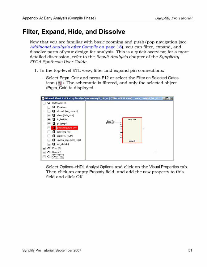
Filter, Expand, Hide, and DissolveNow that you are familiar with basic zooming and push/pop navigation (see Additional Analysis after Compile on page 18), you can filter, expand, and dissolve parts of your design for analysis. This is a quick overview; for a more detailed discussion, refer to the Result Analysis chapter of the Synplicity FPGA Synthesis User Guide.
1. In the top-level RTL view, filter and expand pin connections:
– Select Prgm_Cntr and press F12 or select the Filter on Selected Gates icon ( ). The schematic is filtered, and only the selected object (Prgm_Cntr) is displayed.
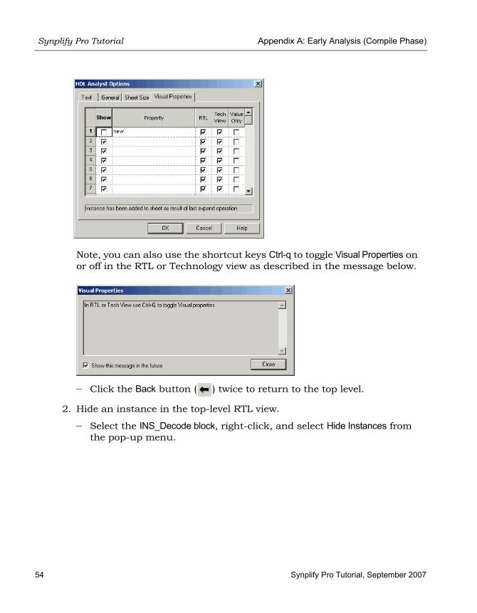
– Select Options->HDL Analyst Options and click on the Visual Properties tab. Then click an empty Property field, and add the new property to this field and click OK.

LO
Synplify Pro Tutorial Appendix A: Early Analysis (Compile Phase)
52 Synplify Pro Tutorial, September 2007
– Make sure that View->Visual Properties is enabled (checked). The new tag appears on any new instance added to the filtered view by subsequent operations.
– To see an expanded view of a pin, click on that pin, right-click to display a menu, and select Expand. The next figure shows an example of an expanded view of a pin.

Appendix A: Early Analysis (Compile Phase) Synplify Pro Tutorial
Synplify Pro Tutorial, September 2007 53
The software expands the connection to the next register and displays it. Because this register is inside Ins_decode, the software indicates hierarchy with a transparent hierarchical instance (a hollow bounding box surrounding the lower-level logic connection).
– Select Options->HDL Analyst Options->Visual Properties and deselect (uncheck) the Show checkbox next to the new property, and click OK.
Transparent hierarchical instance
Opaque hierarchical instance
Select a pin, right-click and select Expand.
New property
LO
Synplify Pro Tutorial Appendix A: Early Analysis (Compile Phase)
54 Synplify Pro Tutorial, September 2007
Note, you can also use the shortcut keys Ctrl-q to toggle Visual Properties on or off in the RTL or Technology view as described in the message below.
– Click the Back button ( ) twice to return to the top level.
2. Hide an instance in the top-level RTL view.
– Select the INS_Decode block, right-click, and select Hide Instances from the pop-up menu.

Appendix A: Early Analysis (Compile Phase) Synplify Pro Tutorial
Synplify Pro Tutorial, September 2007 55
You see a small H in the lower left corner of the instance, which indicates all lower-level hierarchy is “hidden” from certain operations such as expanding.

LO
Synplify Pro Tutorial Appendix A: Early Analysis (Compile Phase)
56 Synplify Pro Tutorial, September 2007
Figure 13: H Indicates a Hidden Instance
– Click in a blank area to deselect everything.
– Select Prgm_Cntr and press F12 or select , the Filter on Selected Gates icon, so that only the selected object (Prgm_Cntr) is displayed.
– Select the same pin as shown below and in step1, right-click, and select Expand.
The results are different, because the internal hierarchy of the hidden instance is not expanded.

Appendix A: Early Analysis (Compile Phase) Synplify Pro Tutorial
Synplify Pro Tutorial, September 2007 57
– Click the Back button ( ) twice to return to the top level.
– Click the RTL icon and open another window with the top-level RTL view. Zoom in and look at the lower left corner of INS_Decode block. It is not hidden in this window, although it is hidden in the first RTL window. You can hide different portions of the design hierarchy in different RTL windows.
– Return to the first RTL window and select INS_Decode. Right-click and select Unhide Instances. The instance is no longer hidden.
– Close one of the windows.
3. View the connections between selected instances.
– In the top-level RTL view select Prgm_Cntr and then, while holding the Ctrl key, select Spcl_Regs.
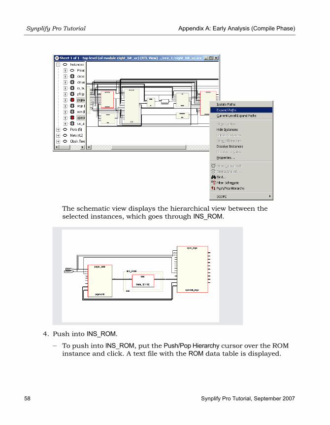
– Right-click and select Expand Paths.
Internal hierarchy of hidden instance is not expanded.
Opaque hierarchical instance
Select a pin, right-click and select Expand.
LO
Synplify Pro Tutorial Appendix A: Early Analysis (Compile Phase)
58 Synplify Pro Tutorial, September 2007
The schematic view displays the hierarchical view between the selected instances, which goes through INS_ROM.
4. Push into INS_ROM.
– To push into INS_ROM, put the Push/Pop Hierarchy cursor over the ROM instance and click. A text file with the ROM data table is displayed.

Appendix A: Early Analysis (Compile Phase) Synplify Pro Tutorial
Synplify Pro Tutorial, September 2007 59
Figure 14:Push into INS ROM
– Close the text window, exit Push/Pop mode, and click the Back button ( ) until you return to the top level.
5. Flatten hierarchy.
– In the top-level view, right-click and select Flatten Schematic from the pop-up menu. The software flattens the entire design.

LO
Synplify Pro Tutorial Appendix A: Early Analysis (Compile Phase)
60 Synplify Pro Tutorial, September 2007
Figure 15:In Top-level RTL View Select Flattened Schematic
– Return to the hierarchical view by right-clicking and selecting UnFlatten Schematic.

Appendix A: Early Analysis (Compile Phase) Synplify Pro Tutorial
Synplify Pro Tutorial, September 2007 61
Note: You cannot use the Back button, because this is a flattened view, not a filtered view. In a flattened view, there is no history, so Back is not available.
– In the unflattened top-level view, select Prgm_Cntr, right-click and select Dissolve Instances.

LO
Synplify Pro Tutorial Appendix A: Early Analysis (Compile Phase)
62 Synplify Pro Tutorial, September 2007
The software flattens the hierarchy for Prgm_Cntr only, and displays a flattened view with the internal logic. It retains the hierarchical context of the rest of the design.
– Return to the full, hierarchical view by right-clicking and selecting Unflatten Schematic (because this is a flattened view and the Back button does not operate). Once you are at the top level, the Back button becomes active and you can go back to the previous flattened view.
6. Dissolve hierarchy in a filtered view.
– In the top-level view, select Prgm_Cntr, hold down the Ctrl key and click on Data_Mux. Click the Filter on Selected Gates icon ( ) to filter these two instances.
– In the filtered view, click in a blank area to deselect the instances, then select Prgm_Cntr. Right-click and select Dissolve Instances. The resulting filtered view shows the internal hierarchy of Prgm_Cntr flattened within a transparent instance. Data_Mux is not flattened.

Appendix A: Early Analysis (Compile Phase) Synplify Pro Tutorial
Synplify Pro Tutorial, September 2007 63
– Click the Back button ( ) until you return to the top level.
The Back button works because this is a filtered view, not a flattened view. Filtered views have history.
7. You can minimize the RTL view, but do not close it.
The rest of the tutorial varies slightly, depending on the technology used. If you do not use the Xilinx vendor, you can follow the methodology used in this flow and substitute device options specific to your vendor.

LO
Synplify Pro Tutorial Appendix A: Early Analysis (Compile Phase)
64 Synplify Pro Tutorial, September 2007