Embed Size (px)
Citation preview

©Synopsys 2012 1
Synopsys Topography Simulations
The Second Quantemol Workshop
Synopsys
London, November 7, 2012

©Synopsys 2012 2
Outline
Sentaurus Topography 3D introduction
SPTOPO3D project setup
Input file for the built in Ionmill model
Input file for the RFM sputtering model

©Synopsys 2012 3
What is TCAD ?
Process Simulation
LDMOS: doping, mesh
1D doping profile simulation
PDE for Pair Diffusion
Mechanical stress in intermetal dielectric
Emulation of 4 CIS cells
PVD (Physical Vapor Deposition)
Device Simulation
Current in Drift-Diffusion Model
Potential distribution in flash memory
Snapback of a UMOS
EM Wave
Inductance Simulation
AlGaAs VCSEL Full Chip H-Bridge

©Synopsys 2012 4
Sentaurus TCAD Product Line
Process
Simulation
Sentaurus Process Framework
Sentaurus
PCM
Studio
Sentaurus Topography
Structure
Editing Sentaurus Structure Editor
Device and
Interconnect
Simulation
Sentaurus Device
Raphael
Sentaurus Interconnect
Sentaurus
Visual
Sentaurus
Workbench

©Synopsys 2012 5
Sentaurus Topography Main Features
• 2D and 3D feature-scale profile simulator, levelset-based
• Built-in empirical models:
– Deposition: LPCVD, PVD, HDP, Electroplating
– Etching: RIE, HDP, Ion-enhanced
• Including physical effects of sputtering, re-emission, re-deposition, and ion reflection
• Input particle flux defined by IAD
• Surface reaction model (2D)
• Programmable Model Interface (PMI, C++)
• User Rate Formulation Model (RFM)
• Integrated with Sentaurus Process and Sentaurus Interconnect
©Synopsys 2012 6
• Sentaurus Topography 3D is a three-dimensional simulator for evaluating and optimizing critical topography-processing steps such as etching and deposition
• It simulates deposition and etching processes by using the level-set method to evaluate the boundary evolution during the process
• Models categories: – Built-in models
– User-defined models within Rate Formula
Module (RFM)
– User-defined models within a Physical
Model Interface (PMI)
• Support of different reaction species,
different fluxes, re-deposition, …
Sentaurus Topography 3D
©Synopsys 2012 7
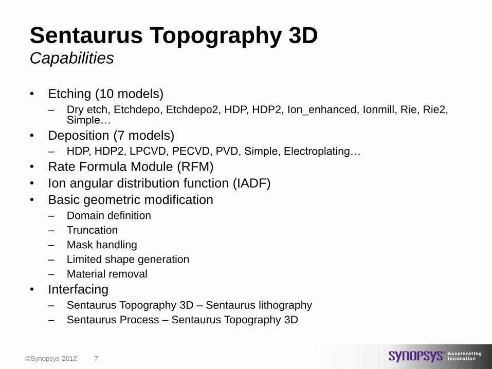
Sentaurus Topography 3D
• Etching (10 models) – Dry etch, Etchdepo, Etchdepo2, HDP, HDP2, Ion_enhanced, Ionmill, Rie, Rie2,
Simple…
• Deposition (7 models) – HDP, HDP2, LPCVD, PECVD, PVD, Simple, Electroplating…
• Rate Formula Module (RFM)
• Ion angular distribution function (IADF)
• Basic geometric modification – Domain definition
– Truncation
– Mask handling
– Limited shape generation
– Material removal
• Interfacing – Sentaurus Topography 3D – Sentaurus lithography
– Sentaurus Process – Sentaurus Topography 3D
Capabilities
©Synopsys 2012 8
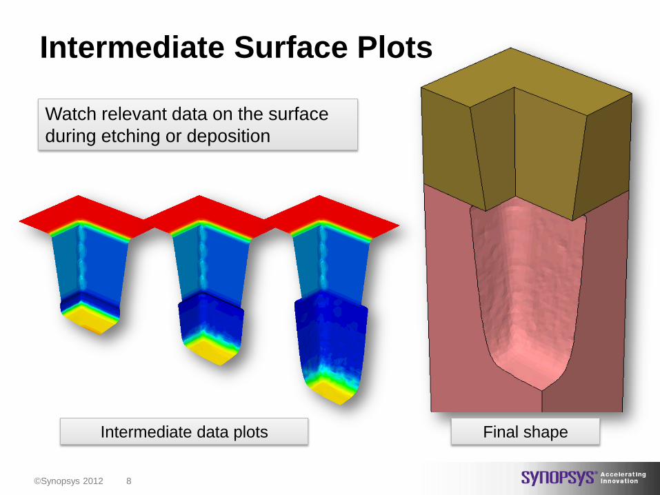
Intermediate Surface Plots
Watch relevant data on the surface
during etching or deposition
Final shape Intermediate data plots

©Synopsys 2012 9
Sentaurus Topography
• Using the Rate Formulation Method (RFM) allows the direct formulation of
etch equations.
• In this example: Etching of Silicon with Chlorine radical species (Fr) flux
and ion fluxes (Fi) , scaling factor Ke, sticking coefficient Sr and the etching
yield Y. The incident ion angle distribution (IAD) is defined by the user.
RFM: Ion-assisted Etch(IE) Equation
# Etch rate calculation
Rate formula easily
translated with a Tcl-like
syntax into a command file.
Fluxes are given by RFM
module, yields and constants
are defined by the user.
𝐸𝑅 = 𝑘𝑒 𝑌 ∙ Γ𝑖𝑜𝑛
1 +𝑌 ∙ Γ𝑖𝑜𝑛𝑆𝑠 ∙ Γ𝑟

©Synopsys 2012 10
Topography to Process Coupling Stress effects during deposition
von Mises Stress

©Synopsys 2012 11
Lithography ↔ Topography Value links between TCAD Sentaurus simulation tools
Litho (Mask 1)
• Sentaurus Lithography for simulation of 2D
and 3D resist profiles, incl. LER
• Sentaurus Topography 2D with chemical
reaction modeling and reactive ion etching
models
• Sentaurus Topography 3D with empirical
models (resolution and size limited)
Etch (hardmask)
Litho (Mask 2)
Etch (poly)
Resist after post-exposure bake
and development (incl. LER)
After etch
Applications
• Double patterning techniques –
process development
• Vertical integration (e.g. FinFET)
• Study impact of process effects and
correction techniques • LER
• Proximity effects
• Corner rounding with spacers
• Process variability
• Links to device simulation Spacer patterning
for FinFET gate
©Synopsys 2012 12
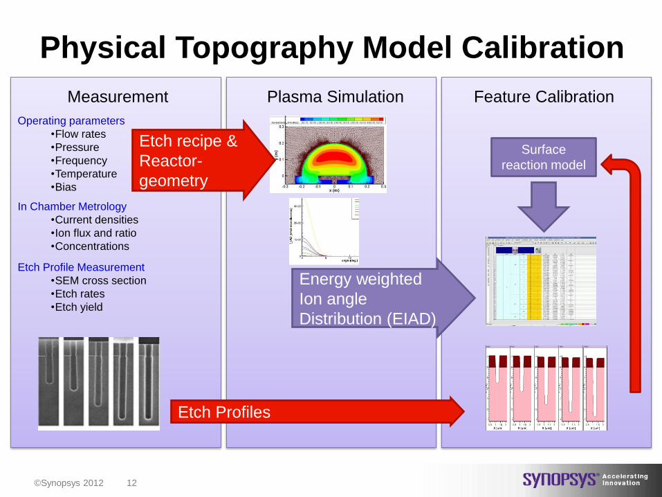
Physical Topography Model Calibration
Measurement Plasma Simulation Feature Calibration
Etch Profiles
Operating parameters
•Flow rates
•Pressure
•Frequency
•Temperature
•Bias
In Chamber Metrology
•Current densities
•Ion flux and ratio
•Concentrations
Etch Profile Measurement
•SEM cross section
•Etch rates
•Etch yield
Energy weighted
Ion angle
Distribution (EIAD)
Etch recipe &
Reactor-
geometry
Surface
reaction model

©Synopsys 2012 13
Outline
Sentaurus Topography 3D introduction
SPTOPO3D project setup
Input file for the built in Ionmill model
Input file for the RFM sputtering model

©Synopsys 2012 14
Sentaurus Topography 3D
• Sentaurus Topography integrated into Sentaurus Workbench (SWB)
• This allows easy parameterization, interfacing and integration of the
topography simulator with other tools
3D SWB Example
SWB
SPTOPO3D
Parameters
and associated
values

©Synopsys 2012 15
Sentaurus Topography 3D 3D SWB Example
Right click the Sentaurus Topography 3D icon
Double click “commands…”
strings in format @string@ are
SWB parameters.
Input file: 1. In case of RFM:
1. Model definition with RFM
including e.g. ion reflection
switched on
2. Definition of yields and constants
values, reflection probabilities,
etc.
2. Etch machine definition
3. Etching using defined etch machine

©Synopsys 2012 16
Outline
Sentaurus Topography 3D introduction
SPTOPO3D project setup
Input file for the built in Ionmill model
Input file for the RFM sputtering model

©Synopsys 2012 17
• Ions sputter material, no IAED information used
• The sputter rate depends on the impact angle and is
given by an yield function:
Ion Mill: Sputtering
imimimim sss 4
4
2
21 coscoscos)(
0
0.5
1
1.5
2
2.5
3
0 10 20 30 40 50 60 70 80 90
Yie
ld f
un
ctio
n (
arb
itra
ry u
nit
s)
nj

©Synopsys 2012 19
Built-in Ionmill Model Example Simulation Results
Oxide
Silicon
Resist
Oxide
Silicon

©Synopsys 2012 20
Outline
Sentaurus Topography 3D introduction
SPTOPO3D project setup
Input file for the built in Ionmill model
Input file for the RFM sputtering model

©Synopsys 2012 21
Feature-Scale Topography Simulation
Reactor Scale
Wafer
Plasma
Inputs:
•Flow rates
•Pressure
•Temperature
•Frequency
Inputs:
Angular distibution and energy distribution
of ions and neutral particles (IADF, IEDF)
Feature-Scale
IAD and IED interface decouples
feature scale from reactor scale

©Synopsys 2012 22
Sentaurus Topography 3D
• Neutrals: Energy-independent fluxes with an isotropic
angular distribution
• Ions: Energy-dependent and energy-independent fluxes
with an anisotropic angular distribution
– Ion angular distributions (IAD)
– Yield function
– Reflection probability
Flux Handling

©Synopsys 2012 23
RFM Sputtering etching Model Example Ion Angular Distribution Input Example
40 mTorr, 1 kW ICP, 0.3 kW
Magnetron, -25 V dc bias, 100 V rf on
coils with -90 V induced dc bias
Integration of
angular distributions
over energies
Ion Flux
normalization
Sentaurus
Topography 3D
Quantemol-D
Plasma Simulation

©Synopsys 2012 24
RFM Flux Definition
... add_ion_flux model=my_model \ name=I reflection=true \ sputtering=true \ sputter_deposition=false \ energy=independent

©Synopsys 2012 25
RFM Sputtering etching Model Example Input File and settings
• Sourcing the model
definition, Yield table and
the IAD table
• Defining the model in use
and its associated
parameters
• Setting the initial structure
• Activating the etching
model
Model definition
User-defined Normalized
sputtering yield table
User-defined IAD
Sputtering rate

©Synopsys 2012 27
RFM Results
Oxide
Silicon
Resist
Oxide
Silicon

©Synopsys 2012 28


![VARI: CERVENKAetal.: TCAD SIMULATION OF … · The 143 process simulations have been set up in Sentaurus Workbench (SWB) of the TCAD simulation package of SYN-OPSYS [3]](https://img.pdfslide.us/doc/110x75/5b5687f07f8b9a022e8c9fb2/vari-cervenkaetal-tcad-simulation-of-the-143-process-simulations-have-been.jpg)
![Free Open Source Mesh Healing for TCAD Device · PDF fileple, Synopsys Sentaurus TCAD provides a structure editor for modeling device geometries [3]. ... Free Open Source Mesh Healing](https://img.pdfslide.us/doc/110x75/5a9cd7257f8b9aba4a8e743e/free-open-source-mesh-healing-for-tcad-device-synopsys-sentaurus-tcad-provides-a.jpg)