Embed Size (px)
Citation preview

SYNCVIBE: Fast and Secure Device Pairing through
Physical Vibration on Commodity Smartphones
Kyuin Lee∗, Vijay Raghunathan†, Anand Raghunathan†, and Younghyun Kim∗∗Department of Electrical and Computer Engineering, University of Wisconsin, Madison, Wisconsin 53706
†School of Electrical and Computer Engineering, Purdue University, West Lafayette, Indiana 47907
Email: ∗{kyuin.lee, younghyun.kim}@wisc.edu, †{vr, raghunathan}@purdue.edu
Abstract—The emergence of the Internet of Things (IoT) andpervasive computing challenges in securely and convenientlyconnecting devices with limited user interfaces. In particular,discovering and bootstrapping a wireless connection (e.g., Wi-Fi and Bluetooth Low Energy) between two devices that shareno prior knowledge, commonly known as pairing, often requiresusers to go through cumbersome tasks of manually discoveringthe target device and entering a long passkey. When the devicesdo not have a proper user interface to enter a passkey, the securityof pairing is often given up, leaving the communication vulnerableto a number of attacks.
To alleviate this challenge, we propose a usable and secureout-of-band (OOB) communication method called SYNCVIBE,leveraging the inherent nature of close-proximity transmission ofmechanical vibration. SYNCVIBE utilizes a vibration motor andan accelerometer, that are already ubiquitously available or easyto embed in mobile and wearable devices, to transmit and receivepairing information. By simply keeping two devices in directcontact, the user can bootstrap a secure, high-bandwidth wirelessconnection without manual pairing procedures. The proposedmethod maximizes accuracy and effective data throughput witha vibration clock recovery technique, which inserts a minimalamount of extra bit patterns to assure synchronization betweenthe transmitter and the receiver. In addition, SYNCVIBE can au-tomatically adjust its detection thresholds in response to variousvibration noises and transmission media. Our implementationof SYNCVIBE demonstrates high-accuracy transmission, provingitself as a suitable OOB communication channel for short datatransmission for secure device pairing.
I. INTRODUCTION
Short-range wireless communication technologies such as
WiFi and Bluetooth Low Energy (BLE) have become ubiqui-
tous in various human-operated devices, such as smartphones,
car infotainment systems, digital media players (e.g., Google
Chromecast), etc. One of the key attributes of communications
in such devices is frequent and short-lived pairing (and unpair-
ing). Pairing is a process for exchanging device information,
e.g., name, address and cryptographic key, to establish a
wireless link between a new pair of devices. Unfortunately,
even in the latest wireless standards, the lack of an intuitive
and simple device pairing method significantly degrades the
user experience. For example, pairing a new smartphone with
a car infotainment system requires a sequence of steps of
discovering nearby devices, selecting the target device, and
entering a passkey, which may be too cumbersome to do just
for spontaneous use.
Target deviceSmartphone
Pairing information
RF data communication
Vibrationmotor
Accelerometer
Fig. 1. Operation of OOB pairing using SYNCVIBE. The smartphonetransmits pairing information to the target device through the vibratory channelusing a vibration motor to bootstrap a high-bandwidth wireless connection.
Pairing methods that are commonly supported by state-of-
the-art protocols and devices can generally be categorized
into three types. First, a new pairing request can be accepted
without any authentication, which is called “Just Works”
operation in Bluetooth. This is common for devices with
limited or no user interface (UI) and provides no defense
against man-in-the-middle (MITM) attacks. Second, as in the
car infotainment system example, the user may be prompted
to enter a passkey generated by one device on the other
device. While this method is generally secure from MITM
attacks unless the attacker is able to obtain the passkey via
some means, e.g., shoulder surfing, the inconvenient user
intervention often thwarts the user. It also requires hardware
components for implementing the UI, e.g., an LCD and
a keypad, which may not be feasible for small, low-cost
devices, such as Bluetooth headphones. Lastly, out-of-band
(OOB) pairing utilizes a secondary channel, such as near-field
communication (NFC), for exchanging pairing information.
The key advantage of OOB pairing is the convenience that
the user does not need to manually enter a passkey, and thus
a longer passkey can be used to enhance security. As long as
the OOB channel is protected from eavesdropping and MITM
attacks, it can be assumed that the wireless channel is also
protected from the same kinds of attacks.
One of the promising OOB channels for secure pairing
is physical vibration generated by a vibration motor or a
piezoelectric vibrator, which can be captured using an ac-
234
2018 IEEE 36th International Conference on Computer Design
2576-6996/18/$31.00 ©2018 IEEEDOI 10.1109/ICCD.2018.00043
celerometer. As shown in Fig. 1, pairing information required
for radio frequency (RF) communication can be transferred
using a physical vibration channel. Physical vibration has
several unique advantages for OOB pairing: i) It is a proximity
channel that requires a direct contact between the transmitter
and the receiver, which makes eavesdropping and MITM
attacks significantly difficult than RF channels. As demon-
strated in earlier works, it can also be protected from acoustic
eavesdropping attacks by generating acoustic noises to mask
audio leakage from vibrating device [1], [2]. ii) Vibration
motors and accelerometers are ubiquitously available in most
mobile and wearable devices. iii) Finally, vibration motors and
accelerometers are low-cost and small-footprint components
that can be easily adopted.
However, the low throughput of vibratory communication is
the key challenge in realizing a practical vibration-based OOB
pairing technique. It can be attributed to two main limitations:
i) the motor driver circuit in mobile devices are designed with-
out consideration of response speed because the slow response
is not a problem for its original purpose of user notification,
and ii) mobile operating systems (Android and iOS) are not
real-time operating systems and do not guarantee the exact
timing of vibration patterns. As a result, conventional vibratory
communication methods suffer from low effective throughputdue to low bitrate and/or synchronization overheads.
In this paper, we propose a novel scheme, named
SYNCVIBE, for enabling accurate vibratory communication
for fast, secure, and convenient device pairing on commodity
smartphones. Compared to previous vibratory communication
schemes, the proposed scheme significantly improves the
effective throughput by maximizing bitrate and minimizing
synchronization overheads. To achieve this goal, we introduce
vibration clock recovery, which extracts timing information
from the non-ideal vibration waveform of data bits by de-
tecting the activation and deactivation of the vibration motor.
Only when the data bits do not contain a bit pattern that can
be used for clock recovery, a short synchronization pattern
is inserted to recover clock with a minimal overhead. We
also present an analysis of the proposed method to optimize
synchronization and maximize throughput. We implement a
prototype and perform a comprehensive evaluation on the
bitrate, error rate, throughput, and pairing success rate. We
also evaluate the prototype under realistic channel conditions
with various vibration noises and protective cases.
II. RELATED WORK
The intrinsic nature of secrecy and human-perceptibility
of physical vibration has been actively studied for secure
short-range communication on commodity mobile devices.
Exploiting vibration generated by a vibration motor or user’s
body motion has been proposed for user authentication or
device authentication for devices carried by the same user [3],
[4], [5], [6]. To modulate data bits into a vibration waveform
using a vibration motor, low-frequency on-off keying (OOK)
scheme has been most commonly used because the motor
driving hardware and software are not capable of controlling
the amplitude and frequency of vibration. In early works, a
short (14-bit) PIN is modulated into vibration and transmitted
to a RFID tag for authentication using OOK at 5 bits per
second (bps) without explicit synchronization [7], [8]. For
the transmission of an extended data length at a high bitrate,
error detection, and correction techniques can be incorporated
with OOK or other modulation schemes at the cost of added
redundancy to guarantee reliable data transmission [9], [10],
[11]. An asynchronous framing method to enclose data bits
with a start bit and an end bit to reduce synchronization error
while sending long sequences of data is proposed in [12]. Due
to the fundamental limitation of slow OOK modulation and the
transmission overhead of synchronization bits, the throughput
of these works is typically limited to a few bps.
To overcome the challenge of low throughput, researchers
have proposed new modulation and demodulation schemes.
Multi-step amplitude shift keying (ASK) and pulse posi-
tion modulation (PPM) achieve data exchanging accuracy
of greater than 95% at 7 bps by varying the amplitude of
generated vibration with different activation periods [13]. The
two-feature OOK scheme proposed in [2] uses the combination
of the amplitude gradient and amplitude mean of the vibration
signal to demodulate fast-changing waveform without full
swing. Although this method enables a higher data bitrate of
up to 20 bps, bit errors and synchronization overheads are not
explicitly considered. Using a linear resonant actuator (LRA)
vibration motor with kernel-level software modifications en-
ables amplitude and frequency modulation and thus can signif-
icantly improve throughput as high as to 80 bps [14], [15], but
this method is only applicable to LRA-type vibrators but not
to eccentric rotating mass (ERM) motors, which is another
prevalent type of vibration motors in today’s smartphones.
Compared to the previous works, our approach achieves higher
data throughput on all commodity smartphones without any
hardware or kernel-level software modifications.
III. CHALLENGES IN FAST VIBRATORY PAIRING
In this section, we discuss challenges in realizing fast
vibratory pairing in commodity smartphones and present some
motivational examples.
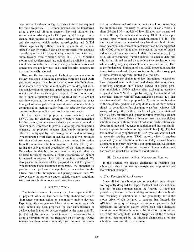
A. Slow Vibration Motor Response
Since all built-in vibration motors in today’s smartphones
are originally designed for haptic feedback and user notifica-
tion, not for data communication, the Android API does not
provide applications with the ability to control the amplitude
and frequency of vibration in a fine granularity, nor is the
motor driver circuit designed to support that. Instead, the
API takes an array of integers as an input parameter that
represents the vibration pattern where each value indicates
durations in milliseconds to turn the vibration motor on or
off, while the amplitude and the frequency of the vibration
are solely determined by the physical characteristics of the
vibration motor and the driver circuit.
235
0 50 100 150 200 250 300 350Time (ms)
0
0.2
0.4V
ibra
tion
(g)
20 ms
100 ms50 ms
200 ms
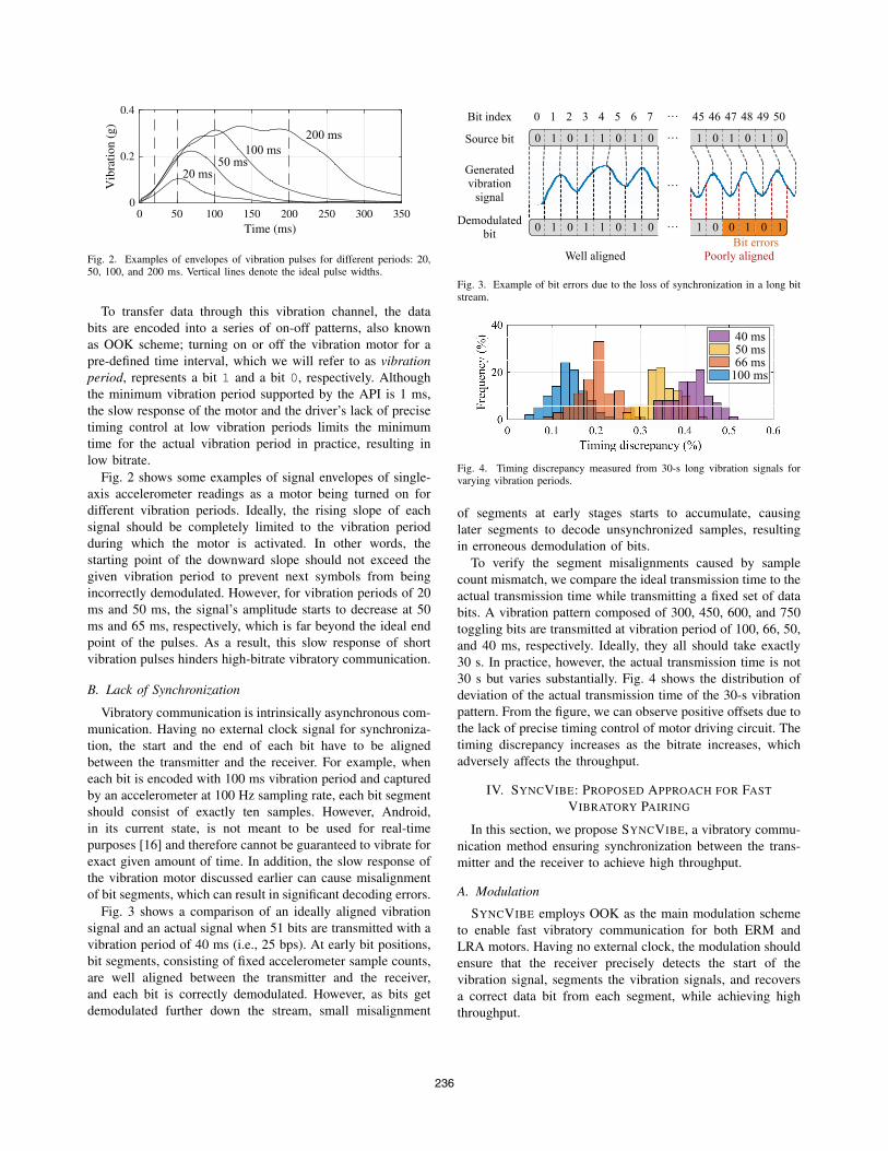
Fig. 2. Examples of envelopes of vibration pulses for different periods: 20,50, 100, and 200 ms. Vertical lines denote the ideal pulse widths.
To transfer data through this vibration channel, the data
bits are encoded into a series of on-off patterns, also known
as OOK scheme; turning on or off the vibration motor for a
pre-defined time interval, which we will refer to as vibrationperiod, represents a bit 1 and a bit 0, respectively. Although
the minimum vibration period supported by the API is 1 ms,
the slow response of the motor and the driver’s lack of precise
timing control at low vibration periods limits the minimum
time for the actual vibration period in practice, resulting in
low bitrate.
Fig. 2 shows some examples of signal envelopes of single-
axis accelerometer readings as a motor being turned on for
different vibration periods. Ideally, the rising slope of each
signal should be completely limited to the vibration period
during which the motor is activated. In other words, the
starting point of the downward slope should not exceed the
given vibration period to prevent next symbols from being
incorrectly demodulated. However, for vibration periods of 20
ms and 50 ms, the signal’s amplitude starts to decrease at 50
ms and 65 ms, respectively, which is far beyond the ideal end
point of the pulses. As a result, this slow response of short
vibration pulses hinders high-bitrate vibratory communication.
B. Lack of Synchronization
Vibratory communication is intrinsically asynchronous com-
munication. Having no external clock signal for synchroniza-
tion, the start and the end of each bit have to be aligned
between the transmitter and the receiver. For example, when
each bit is encoded with 100 ms vibration period and captured
by an accelerometer at 100 Hz sampling rate, each bit segment
should consist of exactly ten samples. However, Android,
in its current state, is not meant to be used for real-time
purposes [16] and therefore cannot be guaranteed to vibrate for
exact given amount of time. In addition, the slow response of
the vibration motor discussed earlier can cause misalignment
of bit segments, which can result in significant decoding errors.
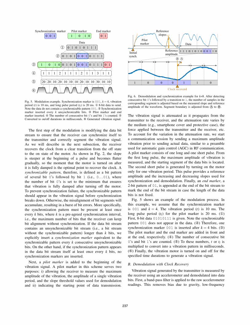
Fig. 3 shows a comparison of an ideally aligned vibration
signal and an actual signal when 51 bits are transmitted with a
vibration period of 40 ms (i.e., 25 bps). At early bit positions,
bit segments, consisting of fixed accelerometer sample counts,
are well aligned between the transmitter and the receiver,
and each bit is correctly demodulated. However, as bits get
demodulated further down the stream, small misalignment
1 0 0 1 0 10 1 0 1 1 0 1 0
Source bit
Generatedvibration
signal…
Demodulatedbit
Bit index 45 46 47 485 49 500 1 2 3 4 6 7 …
Bit errorsWell aligned Poorly aligned
0 1 0 1 1 0 1 0 1 0 1 0 1 0…
…
Fig. 3. Example of bit errors due to the loss of synchronization in a long bitstream.
40 ms50 ms66 ms
100 ms
Fig. 4. Timing discrepancy measured from 30-s long vibration signals forvarying vibration periods.
of segments at early stages starts to accumulate, causing
later segments to decode unsynchronized samples, resulting
in erroneous demodulation of bits.
To verify the segment misalignments caused by sample
count mismatch, we compare the ideal transmission time to the
actual transmission time while transmitting a fixed set of data
bits. A vibration pattern composed of 300, 450, 600, and 750
toggling bits are transmitted at vibration period of 100, 66, 50,
and 40 ms, respectively. Ideally, they all should take exactly
30 s. In practice, however, the actual transmission time is not
30 s but varies substantially. Fig. 4 shows the distribution of
deviation of the actual transmission time of the 30-s vibration
pattern. From the figure, we can observe positive offsets due to
the lack of precise timing control of motor driving circuit. The
timing discrepancy increases as the bitrate increases, which
adversely affects the throughput.
IV. SYNCVIBE: PROPOSED APPROACH FOR FAST
VIBRATORY PAIRING
In this section, we propose SYNCVIBE, a vibratory commu-
nication method ensuring synchronization between the trans-
mitter and the receiver to achieve high throughput.
A. Modulation
SYNCVIBE employs OOK as the main modulation scheme
to enable fast vibratory communication for both ERM and
LRA motors. Having no external clock, the modulation should
ensure that the receiver precisely detects the start of the
vibration signal, segments the vibration signals, and recovers
a correct data bit from each segment, while achieving high
throughput.
236
0 1 0 1 0 1 1 1
0 1 0 1 0 1 1 10 0 1
0 1 0 1 0 1 1 1
0 10101Synchronization marker Pilot marker End marker
0 0 1
0101 0 10 0 1
2 1 1 1 2 1 1 3 1 11 11
20 10 10 10 20 10 10 30 10 1020 1020
Data
Fig. 5. Modulation example. Synchronization marker is 001, k = 4, vibrationperiod (t) is 10 ms, and long pulse period (tl ) is 20 ms. � 8-bit data to send.Note the data do not contain a synchronizable pattern 001. � Synchronizationmarker inserted every k unsynchronizable bits. � Pilot marker and endmarker inserted. � The number of consecutive bit 0’s and bit 1’s counted. �Converted to on/off durations in milliseconds. � Generated vibration signal.
The first step of the modulation is modifying the data bit
stream to ensure that the receiver can synchronize itself to
the transmitter and correctly segment the vibration signal.
As we will describe in the next subsection, the receiver
recovers the clock from a clear transition from the off state
to the on state of the motor. As shown in Fig. 2, the slope
is steeper at the beginning of a pulse and becomes flatter
gradually, so the moment that the motor is turned on after
it is fully damped is the optimal point to recover the clock. A
synchronizable pattern, therefore, is defined as a bit pattern
of several bit 0’s followed by bit 1 (i.e., 0. . .01), where
the number of bit 0’s is set to the minimum that ensures
that vibration is fully damped after turning off the motor.
To prevent synchronization failure, the synchronizable pattern
should appear in the vibration signal before synchronization
breaks down. Otherwise, the misalignment of bit segments will
accumulate, resulting in a burst of bit errors. More specifically,
the synchronization pattern must be present at least once
every k bits, where k is a pre-agreed synchronization interval,
i.e., the maximum number of bits that the receiver can keep
bit alignment without synchronization. If the data bit stream
contains an unsynchronizable bit stream (i.e., a bit stream
without the synchronizable pattern) longer than k bits, we
explicitly insert a synchronization marker equivalent to the
synchronizable pattern every k consecutive unsynchronizable
bits. On the other hand, if the synchronization pattern appears
in the data bit stream itself at least once every k bits, no
synchronization markers are inserted.
Next, a pilot marker is added to the beginning of the
vibration signal. A pilot marker in this scheme serves two
purposes: i) allowing the receiver to measure the maximum
amplitude of the vibration, the amplitude of a single vibration
period, and the slope threshold values used for demodulation
and ii) indicating the starting point of data transmission.
Pilotmarker Data
Referenceslopes
Initialsynch.
Referenceamplitude
1 1 1 0 1 0 1 0 0 0 1 1 0
Clock recoverd
1 0 0 0 1 1 0
Fig. 6. Demodulation and synchronization example for k=8. After detectingconsecutive bit 0’s followed by a transition to 1, the number of samples in thecorresponding segment is adjusted based on the measured slope and referenceamplitude of the waveform. Segment boundary is adjusted from A© to B©.
The vibration signal is attenuated as it propagates from the
transmitter to the receiver, and the attenuation rate varies by
the medium (e.g., smartphone cover and protective case), the
force applied between the transmitter and the receiver, etc.
To account for the variation in the attenuation rate, we start
a communication session by sending a maximum amplitude
vibration prior to sending actual data, similar to a preamble
used for automatic gain control (AGC) in RF communication.
A pilot marker consists of one long and one short pulse. From
the first long pulse, the maximum amplitude of vibration is
measured, and the starting segment of the data bits is located.
The second short pulse is generated by turning on the motor
only for one vibration period. This pulse provides a reference
amplitude and the increasing and decreasing slopes used for
synchronization and demodulation. Finally, an end marker, a
2-bit pattern of 01, is appended at the end of the bit stream to
mark the end of the bit stream in case the length of the data
bits is not fixed.
Fig. 5 shows an example of the modulation process. In
this example, we assume that the synchronization marker
is 001 and k = 4. The vibration period (t) is 10 ms. The
long pulse period (tl) for the pilot marker is 20 ms. (�)
First, 8-bit data 01010111 is given. Note the synchronizable
pattern 001 does not appear in the data. (�) Therefore, one
synchronization marker 001 is inserted after k = 4 bits. (�)
The pilot marker and the end marker are added in front and
at the end, respectively. (�) The number of consecutive bit
0’s and bit 1’s are counted. (�) To these numbers, t or tl is
multiplied to convert into a vibration pattern in milliseconds.
(�) Finally, the vibration motor is turned on and off for the
specified time durations to generate a vibration signal.
B. Demodulation with Clock Recovery
Vibration signal generated by the transmitter is measured by
the receiver using an accelerometer and demodulated into data
bits. First, a band-pass filter is applied to the raw accelerometer
readings. This removes bias due to gravity, low-frequency
237
noises caused by external vibration sources, such as the user’s
body motion, and high-frequency measurement noises. Next,
an envelope detector is applied to obtain a smooth signal
envelope. Fig. 6 shows an example of a vibration signal
envelope and its demodulation. The pilot marker is used for
initial synchronization by locating the starting point of its
first pulse. From the second pulse, we measure the reference
slopes and the reference amplitude. The reference slopes and
amplitude are used for the demodulation of the data waveform
that follows the pilot maker.The data waveform is divided into segments of a fixed
length equal to the vibration period. Each waveform segment
is approximated as a linear function of time. The slope of the
linear function is compared to the reference slopes retrieved
from the pilot marker. If the slope is closer to the increasing
reference slope, the segment is demodulated as a bit 1. On the
other hand, if it is closer to the decreasing reference slope, the
segment is demodulated as a bit 0. Otherwise, if it is closer
to zero, the bit is demodulated as the previous bit. To account
for possible changes of the attenuation of vibration due to
varying pressure applied by the user, the reference slopes are
continuously updated as demodulation progresses.During demodulation, clock is recovered whenever a syn-
chronizable pattern appears in the data. Clock recovery is done
in the same way as the initial synchronization of the pilot
marker; the starting point of the bit 1 after the consecutive
bit 0’s is detected, and rest of the waveform is segmented
again from switching point. The sharp increasing slope after
consecutive bit 0’s makes it possible to precisely detect the
starting point of the segment. A synchronizable pattern that
appears only after k unsynchronizable bits is treated as a
synchronization marker and removed after clock recovery;
otherwise, it is kept as data. Therefore, synchronization mark-
ers inserted on purpose during modulation stage are not
misidentified as data bits. The magnified waveform at the
bottom of Fig. 6 shows an example of the proposed clock
recovery. The synchronizable pattern 001 is highlighted. The
starting point of its last segment is adjusted from A to B ,
and the subsequent segments are also adjusted. If the number
of unsynchronizable bits since the last synchronizable pattern
is equal to k, 001 is a synchronization marker to be removed;
otherwise, it is a part of the data bits.In case the length of data bits is unknown, the receiver
will continue demodulating the absence of vibration as bit 0’s
even after the transmission is completed. When the number of
consecutive 0’s without synchronization exceeds k followed
by no synchronization marker, the receiver can detect the
exact end of the transmission by finding the last appearance
of the end marker pattern. After detecting the end of the
communication session, the end marker is removed to leave
the data bits only.
C. Effective Bits per Second for PairingAs a simplex communication channel without any error
correction or detection scheme, the transfer of pairing infor-
mation should be done with minimal error for OOB pairing.
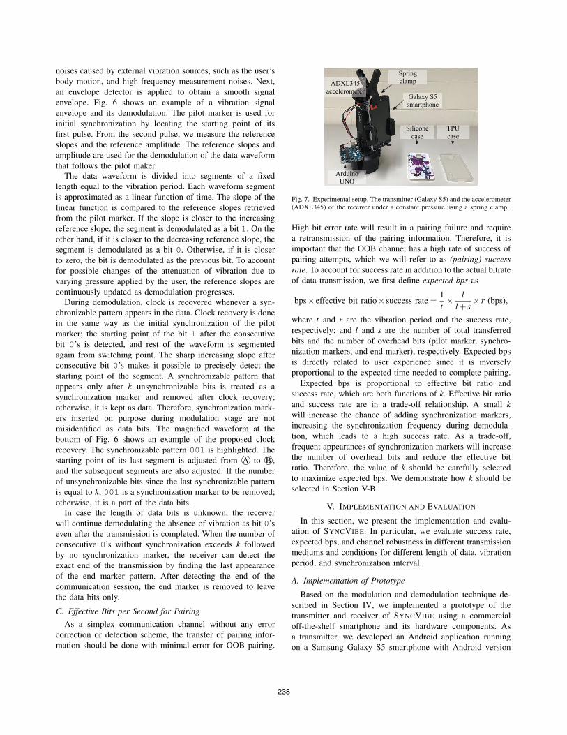
Arduino UNO
Galaxy S5smartphone
ADXL345 accelerometer
Spring clamp
Siliconecase
TPUcase
Fig. 7. Experimental setup. The transmitter (Galaxy S5) and the accelerometer(ADXL345) of the receiver under a constant pressure using a spring clamp.
High bit error rate will result in a pairing failure and require
a retransmission of the pairing information. Therefore, it is
important that the OOB channel has a high rate of success of
pairing attempts, which we will refer to as (pairing) successrate. To account for success rate in addition to the actual bitrate
of data transmission, we first define expected bps as
bps× effective bit ratio× success rate =1
t× l
l + s× r (bps),
where t and r are the vibration period and the success rate,
respectively; and l and s are the number of total transferred
bits and the number of overhead bits (pilot marker, synchro-
nization markers, and end marker), respectively. Expected bps
is directly related to user experience since it is inversely
proportional to the expected time needed to complete pairing.
Expected bps is proportional to effective bit ratio and
success rate, which are both functions of k. Effective bit ratio
and success rate are in a trade-off relationship. A small kwill increase the chance of adding synchronization markers,
increasing the synchronization frequency during demodula-
tion, which leads to a high success rate. As a trade-off,
frequent appearances of synchronization markers will increase
the number of overhead bits and reduce the effective bit
ratio. Therefore, the value of k should be carefully selected
to maximize expected bps. We demonstrate how k should be
selected in Section V-B.
V. IMPLEMENTATION AND EVALUATION
In this section, we present the implementation and evalu-
ation of SYNCVIBE. In particular, we evaluate success rate,
expected bps, and channel robustness in different transmission
mediums and conditions for different length of data, vibration
period, and synchronization interval.
A. Implementation of Prototype
Based on the modulation and demodulation technique de-
scribed in Section IV, we implemented a prototype of the
transmitter and receiver of SYNCVIBE using a commercial
off-the-shelf smartphone and its hardware components. As
a transmitter, we developed an Android application running
on a Samsung Galaxy S5 smartphone with Android version
238

10 20 30 40 50
Synchronization interval, k (bit)
70
80
90
100
Succ
ess
rate
(%
)
10 20 30 40 50
Synchronization interval, k (bit)
60
70
80
90
100
Eff
ectiv
e bi
t rat
io (
%)
50 ms
60 ms
40 ms
(a) (b)
Fig. 8. (a) Pairing success rate for varying synchronization intervals (k)between 10 and 50 bits and different vibration periods (t) of 40, 50, and 60 ms.(b) Worst-case effective bit ratio for varying synchronization intervals (k).
10 20 30 40 50
Synchronization interval, k (bit)
5
10
15
20
25
Exp
ecte
d bp
s (b
ps)
40 ms
50 ms
60 ms
Fig. 9. Expected bps for varying synchronization intervals (k) between 10and 50 bits and different vibration periods (t) of 40, 50, and 60 ms.
6.0. The application takes four inputs: bit length of pairing
information (L), vibration period (t), synchronization interval
(k), and synchronization pattern. We conducted experiments
for t = 40, 50, and 60 ms, which corresponds to 25, 20, and
16.7 bps, respectively. A 5-bit pattern of 00001 is used as the
synchronizable pattern as well as the synchronization marker.
The receiver prototype is implemented using the Arduino UNO
with the ADXL345 MEMS accelerometer (embedded in many
mobile and wearable devices today) at a sampling rate of
1600 Hz. Due to the relatively short communication time, we
assume there will be no significant pressure change between
the transmitter and the receiver from the user. Therefore, the
transmitter and the receiver are clamped together using a
spring clamp, as shown in Fig. 7, to apply constant pressure.
To evaluate the performance of SYNCVIBE under realistic
usage conditions, we tested with two smartphone cases and
two ambient vibration noises in addition to the baseline
condition (without a case and noise).
B. Trade-off in Expected Bits Per Second
First, we evaluate the impact of k to the expected bps. We
measure the pairing success rate using 100 samples of 150-bit
random data bits (L = 150), comparable to the typical length
of Bluetooth’s 128-bit link key, for varying values of k and t.We assume that a pairing attempt is considered successful only
when all 150 bits are demodulated without an error of more
than one bit. To keep the effective bit ratio constant for each k,
we remove synchronizable patterns from the generated random
data bits so that clock is recovered only from explicitly inserted
0 50 100 150
Pairing information, L (bit)
80
85
90
95
100
Succ
ess
rate
(%
)
0 50 100 150
Pairing information, L (bit)
0
20
40
60
80
100
Succ
ess
rate
(%
)
(a) (b)
60 ms50 ms
40 ms60 ms
50 ms
40 ms
Fig. 10. Pairing success rate (a) with and (b) without clock recovery. Notethe different y-axis scale.
synchronization markers. Thus, the effective bit ratio is the
worst-case ratio with the maximum number of synchronization
markers added for given L.
Fig. 8 shows the measured success rate and effective bit
ratio for 10 ≤ k ≤ 50. The effective bit ratio is independent
of t, and it increases as k increases, showing over a 90% of
effective bit ratio for k ≥ 40. For example, when k = 40, the
5-bit synchronization marker is inserted three times, for every
40 bits, resulting in 15 bit overhead (9.1%) in addition to 150
data bits. On the other hand, the success rate decreases as kincreases. It also decreases as the vibration period decreases
since the segments are more likely to be unsynchronized when
the vibration motor is switched more frequently, as shown in
the example in Fig. 4.
This trade-off between the success rate and the effective bit
ratio results in that the expected bps is maximized at k = 30,
35, and 40 for t = 40, 50, and 60 ms, respectively, as shown
in Fig. 9. The figure shows that the maximum expected bps
of 13.5, 16.7, and 19.9 bps is achieved when t is 60, 50, and
40 ms, respectively. We use these optimal k values for the rest
of our experiments.
C. Pairing Success Rate of Different Data Bit Length
Next, we examine the success rate of SYNCVIBE for
varying L. The transmitter attempts to send 25 to 150 bits of
random data (25 ≤ L ≤ 150) at different t, with the optimal kobtained in Section V-B. The data bits generated may contain
synchronizable patterns. The success rate shown in Fig. 10(a)
is around 95%. It does not exhibit a significant dependency
on L thanks to the proposed clock recovery performed during
demodulation that constantly synchronizes the receiver at least
once every k bits. We can also see that t is not a significant
factor to the success rate. SYNCVIBE consistently achieves a
high success rate of 98%, 97%, and 92% with expected bps
of 16.1, 19.0, and 22.2 bps for t = 60, 50, and 40 ms, when
L = 150 bits.
On the other hand, without the clock recovery, the success
rate significantly drops as L increases, as shown Fig. 10(b).
For L ≤ 50 bits, the success rate is above 70% for t = 50
or 60 ms even without clock recovery. However, as bits
get demodulated further down the stream, the probability of
segment misalignment increases and the success rate decreased
239
60 ms 50 ms 40 ms
Vibration period, t (ms)
0
50
100
Succ
ess
rate
(%
)
60 ms 50 ms 40 ms
Vibration period, t (ms)
0
10
20
30
Exp
ecte
d bp
s (b
ps)
Silicone case TPU caseNo case
(a) Success rate
(b) Expected bps
Ideal (16.7)Ideal (20.0)
Ideal (25.0)
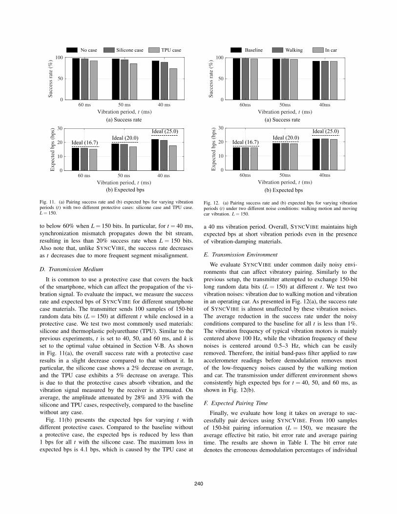
Fig. 11. (a) Pairing success rate and (b) expected bps for varying vibrationperiods (t) with two different protective cases: silicone case and TPU case.L = 150.
to below 60% when L = 150 bits. In particular, for t = 40 ms,
synchronization mismatch propagates down the bit stream,
resulting in less than 20% success rate when L = 150 bits.
Also note that, unlike SYNCVIBE, the success rate decreases
as t decreases due to more frequent segment misalignment.
D. Transmission Medium
It is common to use a protective case that covers the back
of the smartphone, which can affect the propagation of the vi-
bration signal. To evaluate the impact, we measure the success
rate and expected bps of SYNCVIBE for different smartphone
case materials. The transmitter sends 100 samples of 150-bit
random data bits (L = 150) at different t while enclosed in a
protective case. We test two most commonly used materials:
silicone and thermoplastic polyurethane (TPU). Similar to the
previous experiments, t is set to 40, 50, and 60 ms, and k is
set to the optimal value obtained in Section V-B. As shown
in Fig. 11(a), the overall success rate with a protective case
results in a slight decrease compared to that without it. In
particular, the silicone case shows a 2% decrease on average,
and the TPU case exhibits a 5% decrease on average. This
is due to that the protective cases absorb vibration, and the
vibration signal measured by the receiver is attenuated. On
average, the amplitude attenuated by 28% and 33% with the
silicone and TPU cases, respectively, compared to the baseline
without any case.
Fig. 11(b) presents the expected bps for varying t with
different protective cases. Compared to the baseline without
a protective case, the expected bps is reduced by less than
1 bps for all t with the silicone case. The maximum loss in
expected bps is 4.1 bps, which is caused by the TPU case at
60ms 50ms 40ms
Vibration period, t (ms)
0
50
100
Succ
ess
rate
(%
)
60ms 50ms 40ms
Vibration period, t (ms)
0
10
20
30
Exp
ecte
d bp
s (b
ps)
Walking In car
(a) Success rate
(b) Expected bps
Ideal (16.7)Ideal (20.0)
Ideal (25.0)
Baseline
Fig. 12. (a) Pairing success rate and (b) expected bps for varying vibrationperiods (t) under two different noise conditions: walking motion and movingcar vibration. L = 150.
a 40 ms vibration period. Overall, SYNCVIBE maintains high
expected bps at short vibration periods even in the presence
of vibration-damping materials.
E. Transmission Environment
We evaluate SYNCVIBE under common daily noisy envi-
ronments that can affect vibratory pairing. Similarly to the
previous setup, the transmitter attempted to exchange 150-bit
long random data bits (L = 150) at different t. We test two
vibration noises: vibration due to walking motion and vibration
in an operating car. As presented in Fig. 12(a), the success rate
of SYNCVIBE is almost unaffected by these vibration noises.
The average reduction in the success rate under the noisy
conditions compared to the baseline for all t is less than 1%.
The vibration frequency of typical vibration motors is mainly
centered above 100 Hz, while the vibration frequency of these
noises is centered around 0.5–3 Hz, which can be easily
removed. Therefore, the initial band-pass filter applied to raw
accelerometer readings before demodulation removes most
of the low-frequency noises caused by the walking motion
and car. The transmission under different environment shows
consistently high expected bps for t = 40, 50, and 60 ms, as
shown in Fig. 12(b).
F. Expected Pairing Time
Finally, we evaluate how long it takes on average to suc-
cessfully pair devices using SYNCVIBE. From 100 samples
of 150-bit pairing information (L = 150), we measure the
average effective bit ratio, bit error rate and average pairing
time. The results are shown in Table I. The bit error rate
denotes the erroneous demodulation percentages of individual
240
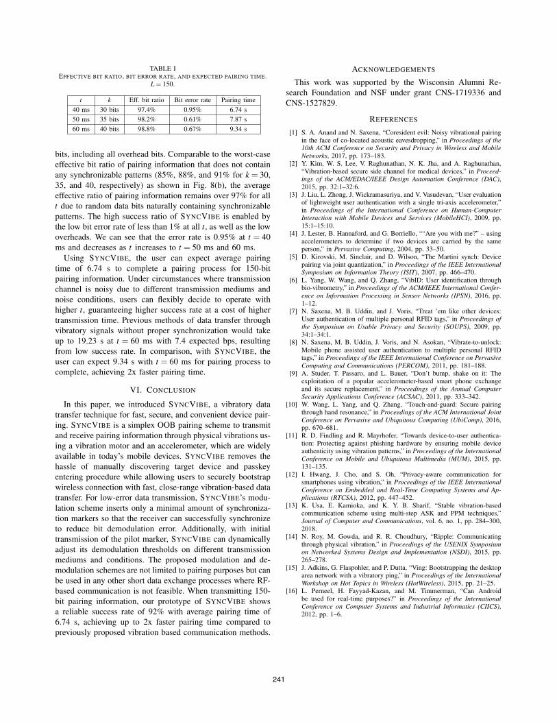
TABLE IEFFECTIVE BIT RATIO, BIT ERROR RATE, AND EXPECTED PAIRING TIME.
L = 150.
t k Eff. bit ratio Bit error rate Pairing time
40 ms 30 bits 97.4% 0.95% 6.74 s
50 ms 35 bits 98.2% 0.61% 7.87 s
60 ms 40 bits 98.8% 0.67% 9.34 s
bits, including all overhead bits. Comparable to the worst-case
effective bit ratio of pairing information that does not contain
any synchronizable patterns (85%, 88%, and 91% for k = 30,
35, and 40, respectively) as shown in Fig. 8(b), the average
effective ratio of pairing information remains over 97% for all
t due to random data bits naturally containing synchronizable
patterns. The high success ratio of SYNCVIBE is enabled by
the low bit error rate of less than 1% at all t, as well as the low
overheads. We can see that the error rate is 0.95% at t = 40
ms and decreases as t increases to t = 50 ms and 60 ms.
Using SYNCVIBE, the user can expect average pairing
time of 6.74 s to complete a pairing process for 150-bit
pairing information. Under circumstances where transmission
channel is noisy due to different transmission mediums and
noise conditions, users can flexibly decide to operate with
higher t, guaranteeing higher success rate at a cost of higher
transmission time. Previous methods of data transfer through
vibratory signals without proper synchronization would take
up to 19.23 s at t = 60 ms with 7.4 expected bps, resulting
from low success rate. In comparison, with SYNCVIBE, the
user can expect 9.34 s with t = 60 ms for pairing process to
complete, achieving 2x faster pairing time.
VI. CONCLUSION
In this paper, we introduced SYNCVIBE, a vibratory data
transfer technique for fast, secure, and convenient device pair-
ing. SYNCVIBE is a simplex OOB pairing scheme to transmit
and receive pairing information through physical vibrations us-
ing a vibration motor and an accelerometer, which are widely
available in today’s mobile devices. SYNCVIBE removes the
hassle of manually discovering target device and passkey
entering procedure while allowing users to securely bootstrap
wireless connection with fast, close-range vibration-based data
transfer. For low-error data transmission, SYNCVIBE’s modu-
lation scheme inserts only a minimal amount of synchroniza-
tion markers so that the receiver can successfully synchronize
to reduce bit demodulation error. Additionally, with initial
transmission of the pilot marker, SYNCVIBE can dynamically
adjust its demodulation thresholds on different transmission
mediums and conditions. The proposed modulation and de-
modulation schemes are not limited to pairing purposes but can
be used in any other short data exchange processes where RF-
based communication is not feasible. When transmitting 150-
bit pairing information, our prototype of SYNCVIBE shows
a reliable success rate of 92% with average pairing time of
6.74 s, achieving up to 2x faster pairing time compared to
previously proposed vibration based communication methods.
ACKNOWLEDGEMENTS
This work was supported by the Wisconsin Alumni Re-
search Foundation and NSF under grant CNS-1719336 and
CNS-1527829.
REFERENCES
[1] S. A. Anand and N. Saxena, “Coresident evil: Noisy vibrational pairingin the face of co-located acoustic eavesdropping,” in Proceedings of the10th ACM Conference on Security and Privacy in Wireless and MobileNetworks, 2017, pp. 173–183.
[2] Y. Kim, W. S. Lee, V. Raghunathan, N. K. Jha, and A. Raghunathan,“Vibration-based secure side channel for medical devices,” in Proceed-ings of the ACM/EDAC/IEEE Design Automation Conference (DAC),2015, pp. 32:1–32:6.
[3] J. Liu, L. Zhong, J. Wickramasuriya, and V. Vasudevan, “User evaluationof lightweight user authentication with a single tri-axis accelerometer,”in Proceedings of the International Conference on Human-ComputerInteraction with Mobile Devices and Services (MobileHCI), 2009, pp.15:1–15:10.
[4] J. Lester, B. Hannaford, and G. Borriello, ““Are you with me?” – usingaccelerometers to determine if two devices are carried by the sameperson,” in Pervasive Computing, 2004, pp. 33–50.
[5] D. Kirovski, M. Sinclair, and D. Wilson, “The Martini synch: Devicepairing via joint quantization,” in Proceedings of the IEEE InternationalSymposium on Information Theory (ISIT), 2007, pp. 466–470.
[6] L. Yang, W. Wang, and Q. Zhang, “VibID: User identification throughbio-vibrometry,” in Proceedings of the ACM/IEEE International Confer-ence on Information Processing in Sensor Networks (IPSN), 2016, pp.1–12.
[7] N. Saxena, M. B. Uddin, and J. Voris, “Treat ’em like other devices:User authentication of multiple personal RFID tags,” in Proceedings ofthe Symposium on Usable Privacy and Security (SOUPS), 2009, pp.34:1–34:1.
[8] N. Saxena, M. B. Uddin, J. Voris, and N. Asokan, “Vibrate-to-unlock:Mobile phone assisted user authentication to multiple personal RFIDtags,” in Proceedings of the IEEE International Conference on PervasiveComputing and Communications (PERCOM), 2011, pp. 181–188.
[9] A. Studer, T. Passaro, and L. Bauer, “Don’t bump, shake on it: Theexploitation of a popular accelerometer-based smart phone exchangeand its secure replacement,” in Proceedings of the Annual ComputerSecurity Applications Conference (ACSAC), 2011, pp. 333–342.
[10] W. Wang, L. Yang, and Q. Zhang, “Touch-and-guard: Secure pairingthrough hand resonance,” in Proceedings of the ACM International JointConference on Pervasive and Ubiquitous Computing (UbiComp), 2016,pp. 670–681.
[11] R. D. Findling and R. Mayrhofer, “Towards device-to-user authentica-tion: Protecting against phishing hardware by ensuring mobile deviceauthenticity using vibration patterns,” in Proceedings of the InternationalConference on Mobile and Ubiquitous Multimedia (MUM), 2015, pp.131–135.
[12] I. Hwang, J. Cho, and S. Oh, “Privacy-aware communication forsmartphones using vibration,” in Proceedings of the IEEE InternationalConference on Embedded and Real-Time Computing Systems and Ap-plications (RTCSA), 2012, pp. 447–452.
[13] K. Usa, E. Kamioka, and K. Y. B. Sharif, “Stable vibration-basedcommunication scheme using multi-step ASK and PPM techniques,”Journal of Computer and Communications, vol. 6, no. 1, pp. 284–300,2018.
[14] N. Roy, M. Gowda, and R. R. Choudhury, “Ripple: Communicatingthrough physical vibration,” in Proceedings of the USENIX Symposiumon Networked Systems Design and Implementation (NSDI), 2015, pp.265–278.
[15] J. Adkins, G. Flaspohler, and P. Dutta, “Ving: Bootstrapping the desktoparea network with a vibratory ping,” in Proceedings of the InternationalWorkshop on Hot Topics in Wireless (HotWireless), 2015, pp. 21–25.
[16] L. Perneel, H. Fayyad-Kazan, and M. Timmerman, “Can Androidbe used for real-time purposes?” in Proceedings of the InternationalConference on Computer Systems and Industrial Informatics (CIICS),2012, pp. 1–6.
241