Embed Size (px)
DESCRIPTION
Electric Machines
Citation preview

s8671,338*

^| - rtoritTf 0tIfyimtvat
F »t»7tciI'MriA

_EMPTY_

o»
tCII>MTIA

_EMPTY_

_EMPTY_

_EMPTY_

_EMPTY_
SYNCHRONOUS MACHINESTheory and Performance
General Electric SeriesSYNCHRONOUS MACHINESby Charles ConcordiaTRANSIENTS IN POWER SYSTEMSby Harold A. PetersonSERVOMECHANISMS AND REGULATING SYSTEMDESIGN, VOLUME Iby Harold Chestnut and Robert W. MayerTRAVELING WAVES ON TRANSMISSION SYSTEMSby L. V. BewleyTRANSFORMER ENGINEERINGby the late L. F. Blume, A. Boyajian, G. Camilli,T. C. Lennox, S. Minneci, and V. M. Montsinger,Second EditionCIRCUIT ANALYSIS OF A-C POWER SYSTEMS, TWOVOLUMESby Edith ClarkeCAPACITORS FOR INDUSTRYby W. C. Bloomquist, C. R. Craig, R. M. Part-ington, and R. C. WilsonPROTECTION OF TRANSMISSION SYSTEMSAGAINST LIGHTNINGby W. W. LewisMAGNETIC CONTROL OF INDUSTRIAL MOTORSby Gerhart W. NeumannPOWER SYSTEM STABILITYVolume I—Steady State Stability; Volume II—Transient Stability; by Selden B. CraryFIELDS AND WAVES IN MODERN RADIOby Simon Ramo and John R. WhinneryMATERIALS AND PROCESSESedited by J. F. YoungMODERN TURBINESby L. E. Newman, A. Keller, J. M. Lyons, andL. B. Wales; edited by L. E. NewmanELECTRIC MOTORS IN INDUSTRYby D. R. Shoults and C. J. Rife; edited by T. C.JohnsonA SHORT COURSE IN TENSOR ANALYSIS FORELECTRICAL ENGINEERSby Gabriel KronTENSOR ANALYSIS OF NETWORKSby Gabriel KronMATHEMATICS OF MODERN ENGINEERINGVolume I by the late Robert E. Doherty andErnest G. Keller; Volume II by Ernest G. KellerVIBRATION PREVENTION IN ENGINEERINGby Arthur L. Kimball
SYNCHRONOUS MACHINESTheory and PerformanceCHARLES CONCORDIAAnalytical Engineering DepartmentGeneral Electric CompanySchenectady, New YorkOne of a series written fay Genera/ Electric authorsfor the advancement of engineering knowledgeJOHN WILEY & SONS, INC., NEW YORKCHAPMAN & HALL, LTD., LONDON, 1951

Copyright, 1951, by General Electric CompanyAll rights reserved. This book or anypart thereof must not be reproduced inany form without the written permissionof the publisherPrinted in the United States of America
PREFACEThe primary object of this book is to present a unified developmentof the fundamental circuit theory of the transient performance of syn-chronous machines as currently used by the engineers directly concernedwith the prediction of machine performance. The material was writtenfor a synchronous machines course that has been given at the GeneralElectric Company for the past three years. The general equationsdeveloped are applied to the calculation of transient short-circuit cur-rents and torques; steady-state power, torque, and current, both insynchronous operation and during starting; and the voltage disturbancesoccasioned by sudden application of load. Emphasis is on a more orless rigorous mathematical development and on obtaining a fundamentalphysical understanding of the machine so that the reader will be bestequipped to extend the theory as he needs it.It is presumed that the reader is acquainted, but not necessarilyfamiliar, with1. The ordinary steady-state and transient theory of static circuitsincluding the elementary law of electromagnetic induction in circuits.2. The general physical appearance of a synchronous machine.3. Ordinary differential equations, and operational calculus in at leastone of its various forms.4. A usual undergraduate course in round-rotor a-c rotating electricmachinery, covering only the steady-state performance.5. Symmetrical components.6. The per-unit system of representation of machine and power systemparameters.Thus, the book is intended primarily for the practicing engineer whowants to learn something about the transient theory of synchronousmachines and who has heretofore been obliged to dig through the tech-nical literature of the past twenty-five years to do so. It is not intendedas a reference book, even though formulas for many specific cases canbe found in it. On the contrary, it is intended to be read as a wholefrom the beginning.It will be evident to those familiar with the literature of synchronousmachines that for the sake of unity many of the derivations and thenotation, and in some cases the form of the results, have been revised.

vi PREFACEIn particular, the method of deriving the general equations and thetreatment of single-phase short circuits had to be considerably revised.Also, certain new material has been added. These new items are: thetreatment of the double-line-to-ground short circuit, of the unidirectionalcomponents of short-circuit torque, of the starting torque, and of voltagedip on application of load. -The theory presented in this book is the culmination of the work ofmany engineers over a period of about twenty-five years. Acknowledg-ment of sources can therefore be made only through the list of referencesand the bibliography, as they are otherwise literally too numerous tomention. However, I want to acknowledge specifically the continuedencouragement and support of Mr. S. B. Crary and the contributionsto the point of view made by Mr. Gabriel Kron. I must remark furthermy conviction that an essential factor in the achievement of such qualityas this book may have is the atmosphere of a large industrial corporation,that combines the necessity for keeping in direct contact with the latestpractice with the opportunity for specialization afforded by its size.CHARLES CONCORDIAMarch 1951
CONTENTSCHAPTER PAGE1 PHYSICAL DESCRIPTION OF A SYNCHRONOUS MACHINE 12 MATHEMATICAL, DESCRIPTION OF A SYNCHRONOUS MACHINE 6Voltage Relations, 8 Flux-Linkage Relations, 9 Inductance Rela-tions, 10 Transformations of Equations, 13 Armature Voltage Equa-tions, 16 The Operational Impedances, 18 Per-Unit Quantities, 20Slip Test for xd and xq, 23 Short-Circuit Test for xd, 24 Zero-Sequence Reactance, 25 Power Output, 25 Torque, 28 Sum-mary, 30 Problems, 313 STEADY-STATE, BALANCED, SYNCHRONOUS OPERATION 32The Steady-State Vector Diagram, 32 Field Flux Linkage, 34 PowerOutput, 36 Power-Angle Characteristics, 37 Stability, 40 ReactiveVolt-Amperes, 44 Power-Angle Characteristics for Two Machines, 46Summary, 52 Problems, 524 THREE-PHASE SHORT-CIRCUIT CURRENT 54Synchronizing Currents, 58 Steady-State Components of Short-CircuitCurrent, 59 Short-Circuit Test, 66 Short Circuit with Armature Resistance, 67 Field Current, 72 Summary, 74 Problems, 755 SINGLE-PHASE SHORT-CIRCUIT CURRENT 76Line-to-Line Short Circuit, 76 Phase Quantities, 81 Line-to-Neu-tral Short Circuit, 81 Open-Phase Voltage for Line-to-Line Fault, 84Harmonic Components of Voltage and Current, 85 Decrement Factors,90 Field Current, 95 Summary, 97 Problems, 986 DoUBLE-LINE-TO-GROUND SHORT CIRCUIT AND SEQUENTIAL FAULTS . . 100Symmetrical Components, 103 Rotor Decrement Factors, 108 Statoror Armature Decrement Factors, 109 Field Current, 112 Open-PhaseVoltage, 113 Sequential Application of Faults, 114 Summary, 117Problems, 1187 SHORT-CIRCUIT TORQUES 119Three-Phase Short Circuit with All Resistances Neglected, 119 Three-Phase Short Circuit—Effect of Armature Resistance, 121 Three-PhaseShort Circuit—Effect of Rotor Resistance, 123 Discussion of Three-Phase Short-Circuit Torques, 127 Line-to-Line Short Circuit, 134Torque, 135 Other Types of Short Circuit, 142 Harmonic Compo-nents of Line-to-Neutral Torque, 145 Unidirectional Components ofTorque, 147 Unidirectional Component of Torque Due to D-C Compo-nent of Current, 157 Approximate Torque Equations, 160 Summary,163 Problems, 164vii
viii CONTENTSCHAPTER PAGE8 STARTING TORQUE 165Equivalent Circuit, 171 Relation to Approximate Torque Equation, 171Comparison of "Exact" and Approximate Methods, 175 Average Torque(d- and g-Axis Method), 177 Field Excitation, 180 Summary, 183Problems, 1849 VOLTAGE DIP 185Effect of Voltage Regulator, 191 Minimum Voltage, 193 RequiredExciter Ceiling, 195 Saturation, 196 Exciter Response, 197 Volt-age Recovery Time, 200 Effect of Initial Load, 200 Field Current,201 Summary, 202 Problems, 203APPENDIXA FOURIER SERIES FOR CURRENTS, AND FUNDAMENTAL-FREQUENCY COMPO-NENTS OF id AND lq, FOR DoUBLE-LINE-TO-GROUND FAULT 205B TORQUE 212REFERENCES 216BIBLIOGRAPHY 217INDEX ..........,,....,,............ 221

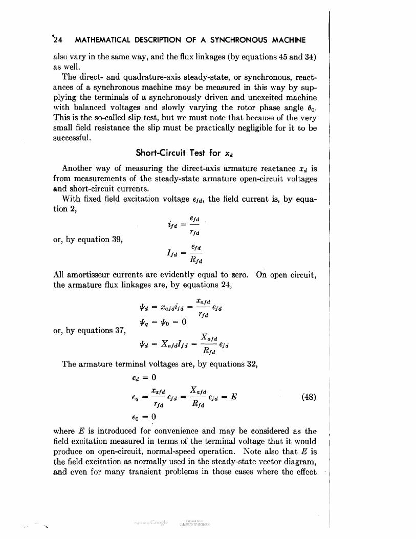
1PHYSICAL DESCRIPTIONOF A SYNCHRONOUS MACHINEA synchronous motor or generator consists essentially of two elements:the first to produce a magnetic field, the second ajset of armature coilsin which voltages are produced by the relative motion of the two ele-ments. In the usual modern machine the field structure rotates withina stator which supports and provides a magnetic-flux path for thearmature windings. The exciting magnetic field is ordinarily producedby a set of coils (the field winding) on the moving element or rotor.Since most electric power is generated (and in the case of large blocksof power, consumed) as three-phase power, there are ordinarily threearmature coils, disposed around the stator at 120° intervals so that,with uniform rotation of the magnetic field, voltages displaced 120° inphase will be produced in the coils. Two observations about this laststatement are in order here.1. It only applies without qualification to a two-pole (i.e., one pairof poles) machine. In a machine with, e.g., two pairs of poles, theremust be correspondingly two complete sets of armature coils 180° apart,the three coils of each being set 60° apart. Figure 1 illustrates the dis-position of the coils and the magnetic-flux paths for a two- and four-pole machine. More generally, the three coils of each set must be(120/n) degrees apart, and the sets (360/n) degrees apart, where n isthe number of pairs of poles. It is usual and convenient to measure thedistance between coils in "electrical degrees" where 360 electrical degreescorresponds to the angle included in one pole pair and 360 actual (ormechanical) degrees equals 360n electrical degrees. In terms of elec-trical degrees, then, the three coils of each set are always 120° apart.2. The steady-state voltages produced (with balanced load) are al-ways 120° apart in phase regardless of the speed of rotation of the field.That is, since (1/n) revolution (a displacement equal to the space oc-cupied by one pole pair) will always correspond to one cycle of the gen-1

PHYSICAL DESCRIPTION OF A SYNCHRONOUS MACHINESTATOR COIL SIDES
Fio. 1. Arrangement of coils in 2- and 4-pole machines

PHYSICAL DESCRIPTION OF A SYNCHRONOUS MACHINE 3erated voltage, i.e., the fundamental frequency will always be exactlyn times the speed of rotation, and, since with constant rate of rotationthe time required for the rotor to move any given distance is propor-tional to the distance moved, the time required for the field to movefrom any given position with respect to one coil to the correspondingposition with respect to the next coil is just one third of a cycle or 120electrical degrees. Of course, the machine is ordinarily connected to athree-phase bus to which voltage is also being supplied by other syn-chronous machines, so that this applied voltage will not correspond tothe rotational speed unless the machine is running in synchronism withthe rest of the machines on the system. Hence, the term "synchronousmachine" means one that ordinarily runs in synchronism with othermachines of the same general type, and the terms synchronous opera-tion, out of synchronism, and out of step have meaning only for a ma-chine connected to a system, and not for a single machine operatingalone.Since in normal operation the magnetic flux produced by the fieldwinding is rotating with respect to the stator windings and its support-ing magnetic structure, voltages are produced in the iron as well as inthe coils, and it is necessary to laminate the stator iron in order to breakup the eddy-current paths and thus minimize the i2r losses and short-circuiting effect which would otherwise result.The field structure or rotor on the other hand sustains principallyonly a constant flux and so does not have to be laminated throughout.When balanced three-phase armature currents of speed frequency areflowing, the mmf's produced by these currents tend to combine to givea resultant mmf that rotates at the same speed as the field. It is foundthat the best way to study the effects of this armature mmf is to resolveit into its space harmonics, upon which it may be discovered that thefundamental component rotates at rotor speed and so is stationary withrespect to the field, while some of the space harmonics rotate at dif-ferent speeds and so are moving with respect to the field. Since thearmature coils are distributed along the stator surface so as to tend tominimize all harmonics other than the space fundamental, these har-monic effects may be regarded as secondary from the standpoint ofperformance. They contribute to the armature leakage reactance (i.e.,to components of armature flux which do not link any of the rotor wind-ings) and to rotor surface eddy-current losses which make it desirableto laminate at least the surface of the rotor iron whenever possible. Ingeneral, practically all machines except high-speed, two- or four-poleturbine-generators have laminated pole faces and are constructed withsalient poles as shown in Fig. 2, whereas the rotors of two- and four-

4 PHYSICAL DESCRIPTION OF A SYNCHRONOUS MACHINEpole machines may be made as a single solid piece of steel. In Fig. 2can also be seen a damper winding or amortisseur consisting usually ofa set of copper or brass bars set in pole-face slots and connected together
Fig. 2. Rotor for salient-pole machine.j^isE!A-^|ggHNMHj[.uuu,e*w ,n , '.§ T^&W• ■ m<WFig. 3. Rotors for solid-rotor machinesat the ends of the machine. This amortisseur has several useful func-tions: x to permit starting of synchronous motors as induction motorsusing the amortisseur as equivalent to the squirrel cage of an induction-motor rotor, to assist in damping rotor oscillations, to reduce overvolt-ages under certain short-circuit conditions, and to aid in synchronizingthe machine.1 Superscripts refer to items in the list of references at the end of the book.

PHYSICAL DESCRIPTION OF A SYNCHRONOUS MACHINE 5Figure 3 shows two rotors for two-pole solid-rotor turbine-generators.In this case the solid steel rotor itself serves the purpose of the amor-tisseur.From the brief description given above it is evident that the statorand rotor of a synchronous machine differ in these respects: The statoris more or less standardized and relatively simple in form for any typeof synchronous machine and is, moreover, completely symmetrical withrespect to any of the three phases. On the other hand, the rotor pre-sents a considerable variety of forms, ranging from the simplest caseof a single field winding on an otherwise symmetrical laminated rotorto a salient-pole rotor with an amortisseur having several windings, orto a solid rotor, which, although symmetrical except for the field, isstill complex in that the solid steel rotor may be considered as equivalentto an amortisseur of infinitely many circuits.
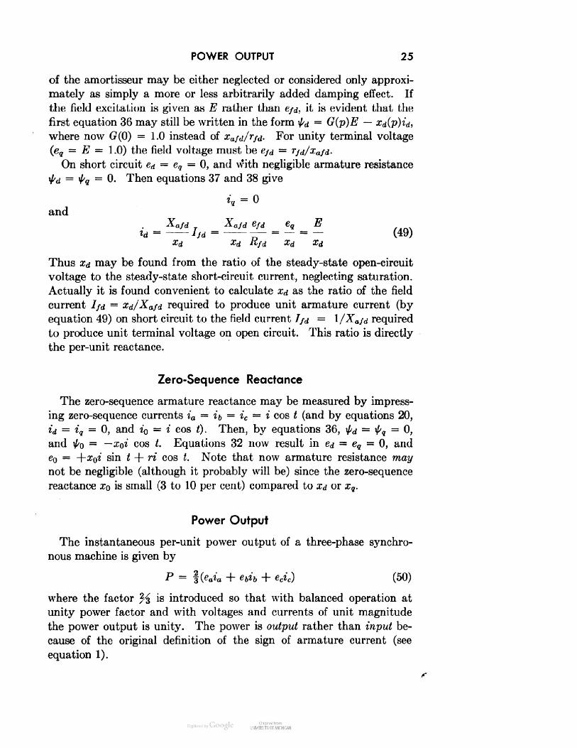
2MATHEMATICAL DESCRIPTIONOF A SYNCHRONOUS MACHINEWe have pointed out in Chapter 1 that a synchronous machine con-sists of two major components, the stator and the rotor, that are inrelative motion and that are rather different in structure. Regardlessof this it is of course possible to write down the circuit-voltage equationssimply in terms of the self- and mutual inductances of all the windings.In order to do this, we must first decide what the rotor windings are.We shall assume that the rotor magnetic paths and all of its electriccircuits are symmetrical about both the pole and interpole axes as shownin Fig. 4 for a salient-pole machine. The field winding is of courseseparate from the others and has its axis in line with the pole axis. Theamortisseur bars are all connected together in a more or less continuousmesh, but, if they are arranged symmetrically, current paths may bechosen which are also symmetrical about both the pole and interpoleaxis. Figure 4 shows the circuits used. The bars are numbered startingfrom the direct axis, which is in line with the pole axis. The direct axiscircuits are then numbered Id, 2d, etc., to correspond with these bars.In the quadrature axis, which is taken as 90 electrical degrees ahead ofthe direct axis in the direction of normal rotor rotation, the circuitsare numbered Iq, 2q, etc., starting outward from this axis. This sym-metrical choice of the rotor circuits has the virtue of making all mutualinductances and resistances between direct- and quadrature-axis rotorcircuits equal to zero. In some machines the amortisseur bars are notconnected between poles, but even in these cases current may flow be-tween poles at the ends of the machine through the rotor iron itselfsince the bars are not insulated. This lack of insulation means also thatthe circuit equations are only approximations to the actual case, inwhich some current may spread through the iron. This effect is smallexcept where the interpole iron path is concerned, and except in turbine-generators wherein the currents in the iron form the whole amortisseur6

MATHEMATICAL DESCRIPTION OF A SYNCHRONOUS MACHINE 7effect. Since the turbine-generator is so different in this respect fromthe salient-pole generator, it will be treated separately after we haveseen how the salient-pole case turns out.All mutual inductances between stator and rotor circuits are periodicfunctions of rotor angular position. In addition, because of the rotorsaliency, the mutual inductances between any two stator phases arealso periodic functions of rotor angular position. We thus arrive at aPOLE I">•>d Id dl
It Ij^^M-.-^-.-M-NUMBERING OF ROTOR CIRCUITSFIQ. 4. Diagram of amortisseur circuitsset of differential equations most of whose coefficients are periodic func-tions of rotor angle, so that even in the case of constant rotor speed(when the equations are linear if saturation is neglected) they are awk-ward to handle and difficult to solve. However it is found that, if cer-tain reasonable assumptions are made, a relatively simple transforma-tion of variable will eliminate all these troublesome functions of anglefrom the equations.The first assumption is that the stator windings are sinusoidally dis-tributed along the air gap as far as all mutual effects with the rotor areconcerned. This assumption of sinusoidal distribution of the statorwindings may be justified from the standpoint that in practically allsynchronous machines the windings are distributed so as to minimizeall harmonics as much as is feasible.2 The principal justification comesfrom the comparison of performance calculated on that basis with actualperformance obtained by test.

8 MATHEMATICAL DESCRIPTION OF A SYNCHRONOUS MACHINEThe second assumption is that the stator slots cause no appreciablevariation of any of the rotor inductances with rotor angle. This assump-tion is evident for machines with a large number of slots per pole, butfor machines with a very small number (especially an integral number)of slots it is not so evident. However, a small number of slots occursprincipally in machines having a large number of poles, and thus anyeffect of the slots may be made to average out over the whole machine.Again the final justification comes from comparison of theory and testresults.A third assumption which will be made in this book at least for thepresent is that saturation may be neglected. The effects of variousassumptions regarding saturation will be shown later.The electrical performance of a synchronous machine may now bedescribed by the following equations.Voltage RelationsARMATURE OR STATORea ~ Pta — riatb = ptb — rib (1)ec = p\l/c — ricwhere ea = terminal voltage of phase afa = total flux linkage in phase aia = current in phase a. Note that the direction of positivearmature current is taken as opposite to what might havebeen expected in a static network in order to have positivecurrent correspond to generator action.a, b, c, are the three phases lettered in the direction of rotorrotation as shown in Fig. 5r = resistance of each armature winding, assumed to be the samefor a, b, cp = the derivative operator d/dt, t = timeFIELD+ Wd (2)where here and in all the following equations the symbols e, t, i havethe same meaning as above, the subscripts denoting the circuit inquestion.
FLUX-LINKAGE RELATIONS 9DIRECT-AXIS AMORTISSEUR0 = ptid + rudiid + ri2di2d -\ ----0 = pfad + r2idiid + r22di2d H ---- (3)etc.Here the subscripts I2d and 2ld denote mutual effects between cir-cuits Id and 2d (see Fig. 4). It may be noted that the amortisseurcircuits are resistar 2e-coupled as well as inductance-coupled and thatthere is no coupling between direct- and quadrature-axis circuits be-cause of the rotor .symmetry about the direct and quadrature axes.QUADRATURE-AXIS AMORTISSEUR0 = ptiq + rnqiiq + rl2qi2q -\ ----0 = pt2q + r2iqiiq + r22qi2g -\ ---- (4)etc.Flux-Linkage RelationsARMATURE— XbbH ~ Xbcic + Xbfdifd ++ xc2di2d -\ ----- h xclqilq + xc2qi2q H ---- (5)where the x's are inductances to be defined later and the subscriptsrefer, as before, to the circuits in question.FIELD^/d = —Xfadia ~ Xfbdtb ~ Xfcdlc + Xffdifd + Xf idild+ Xf2di2d H ----- h Xfiqiiq + xf2qi2q -\ ---- (6)

10 MATHEMATICAL DESCRIPTION OF A SYNCHRONOUS MACHINEDIRECT-AXIS AMORTISSEURtld = — xiadia — Xlb<flb ~ Xlcdic + Xlfdifd + Xlldild+ Xl2,fl2d + ' ' ' + Xldlqilq + XldZqiZq + ' ' ') 6tC. (7)QUADRATURE-AXIS AMORTISSEUR(8)+ Xlq2cfi2d -\ ----- h+ Z12^29 HInductance RelationsARMATURE SELF-INDUCTANCESThe self-inductance of any armature winding varies periodically froma maximum when the pole axis is in line with the phase axis to a mini-mum when the interpole axis is in line with the phase axis. BecauseAXIS OF PHASE aPOLE, OR DIRECTAXIS
INTERPOLE, ORQUADRATURE AXISFIG. 5of the symmetry of the rotor, the inductance must have a period of 180electrical degrees and must be expressible by a series of cosines of evenharmonics of angle. It will be shown that under the assumption of

INDUCTANCE RELATIONS 11sinusoidal winding distribution only the first two terms of the seriesare significant, orXaa = ZaaO + Xaa2 COS 26a (9)where 6a is the angle of the direct axis from the axis of phase a, measuredin the direction of rotor rotation.Because of the sinusoidal winding distribution, current in phase a pro-duces a space wave of mmf in the air gap which is only of fundamentalspan as far as the rotor is concerned. This may conveniently be brokenup into components proportional to (cos 0a) and (— sin 0a) acting in thedirect and quadrature axes, respectively (see Fig. 5). These componentsof mmf produce corresponding components of flux having space funda-mental components of magnitude (<j>d = Pd cos 0a) and (4>q = — Pq sin 0Jwhere Pd and Pq are proportional to effective permeance coefficientsin the direct and quadrature axes, respectively. Space-harmonic com-ponents of flux are also produced, but, since they do not link the stator,they do not concern us now. The linkage with phase a caused by thisflux is then proportional to (see Fig. 5)<t>d cos 0a —^g sin 0a = Pd cos2 0a + Pq sin2 0a= .Pd + P" + Pd~PqCOS26a = A + BCOS26a2 2(10)There is also some flux linking phase a that does not link the rotor.This flux adds only to the constant term A of equation 10, and so theinductance remains of the form of equation 9.Similarly,Xbb = XaaO + Xaa2 COS 26b(11)Xee = XaaO + Xaa2 COS 20cwhere06 = 6 - 120° (12)0c = 0 + 120°ARMATURE MUTUAL INDUCTANCESTo determine the form of the mutual inductance between, e.g., phasesa and b, we may recognize first that there may be a component of mutualflux that does not link the rotor and is thus independent of angle. Then
12 MATHEMATICAL DESCRIPTION OF A SYNCHRONOUS MACHINEconsidering current in phase a, the components of air-gap flux are, asbefore, proportional to<t>d = Pd cos 6aand<t>g = -Pg sin 6a (13)and the linkage with phase 6 due to these components is proportional to<t>d cos 6b — <t>q sin 0(, = Pd cos 0a cos 6b + Pq sin 0a sin 6b= Pd cos 6 cos (6 - 120) + Pq sin 6 sin (0 - 120)- Pq+ - - cos 2(6 - 60°)4 2= - JA + B cos 2(0 - 60°)= -[£A + £ cos 2(0 + 30°)]The total mutual inductance is thus of the form,Xab = — [XabO + Xaa2 COS 2(0 + 30°)]Note that the variable part of the mutual inductance is of exactlythe same magnitude as that of the variable part of the self-inductanceand that the constant part has a magnitude of very nearly half that ofthe constant part of the self-inductance. Now that we know the answer,it may seem obvious from symmetry considerations that the mutualinductance ab should have a (negative) maximum when the pole axisis lined up 30° behind phase a or 30° ahead of phase b, and a (negative)minimum when it is midway between the two phases. We might alsohave reasonably taken a chance that higher harmonic terms could notappear in the mutual inductance since they dropped out of the self-inductance.Finally, we can write all the stator mutual inductances asXab = Xba = ~[XabO + Xaa2 COS 2(0 + 30°)]Xbc = Xcb = — [XaW + Xaa2 COS 2(0 — 90°)] (14)ab0 + £aa2 COS 2(0 + 150°)]ROTOR SELF-INDUCTANCESSince we are neglecting the effects of stator slots and of saturation,all the rotor self-inductances, £//d, xnd, x22d, £119, etc., are constants.

TRANSFORMATIONS OF EQUATIONS 13ROTOR MUTUAL INDUCTANCESAll mutual inductances between any two circuits both in the directaxis and between any two circuits both in the quadrature axis are con-stant, and of course xfld = xifd, etc. Because of the rotor symmetrythere is no mutual inductance between any direct- and any quadrature-axis circuit. Thus:Xflq ~ xf2q = Xldlq = xld2q = xlqfd = ^l«ld = xlq2d = 0, etc. (15)MUTUAL INDUCTANCES BETWEEN STATOR AND ROTOR CIRCUITSBy considering current in each rotor winding in turn and recallingthat only the space-fundamental component of the flux produced willlink the sinusoidally distributed stator, we see that all stator-rotormutual inductances vary sinusoidally with angle and that they aremaximum when the two coils in question are in line. Thus:Xald = Xfad = Xafd COS 6Xbfd = Xfbd = Xafd COS (0 — 120)Xcfd = Xfcd = Xafd COS (0 + 120)Xal d = Xiad = Xald COS 6Xbl d - Xibd = Xald COS (6 — 120) (16)xcld = xUd = Xau cos (6 + 120), etc.Xalq = Xlaq = — Xalq SU1 6Xblq = XUq = — Xalq SU1 (6 - 120)Xciq = xUq = -xalq sin (6 + 120), etc.Transformations of EquationsUtilizing the mutual-inductance relations equations 16, we may re-write the rotor flux-linkage equations 6, 7, and 8 asFIELDtfd = — xafd[ia cos 6 + ib cos (0 — 120) + ic cos (6 + 120)]+ Xffdifd + xfidiid + xndiid + • • • (17)
14 MATHEMATICAL DESCRIPTION OF A SYNCHRONOUS MACHINEDIRECT-AXIS AMORTISSEURtid = —xaid[ia cos 6 + ib cos (6 - 120) + ie cos (6 + 120)]+ xndiid + xi2di2d -\ ---- , etc. (18)QUADRATURE-AXIS AMORTISSEUR\h9 = +xaig[ia sin 6 + ib sin (6 - 120) + ic sin (6 + 120)]+ Xi2qi2q H ---- , etc. (19)The form of these equations suggests that they may be simplified bythe substitution of new variables id, iq, IQ defined by the relations : sid = f ta cos 6 + ib cos (6 - 120) + ic cos (6 + 120)]iq = - f [*'a sin 6 + i b sin (6 ~ 12O) + ic sin (0 + 120)] (20)By reference to Fig. 5, or for that matter by inspection of equations 17,18, and 19, we see that id and iq are proportional to the components ofmmf in the direct and quadrature axes, respectively, produced by theresultant of all three armature currents ia, ib, and ic. The factor %is introduced so that, for balanced phase currents of any given (maxi-mum) magnitude, the maximum values of id and iq as the phase of thecurrents is varied will be of the same magnitude. The maximum mag-nitude of any one of the phase currents under these balanced conditionswill be given by V i2d + i2q and will also be the same.The current i0 is introduced since, if three currents ia, 4, and ic areto be eliminated, in general three substitute variables will be required.i0 is the conventional zero-phase-sequence current of symmetrical-com-ponent theory, and, if only i0 exists (i.e., if ia = ib = ie), equations 17,18, and 19 show that no flux will link the rotor.By substituting the relations 20 in equations 17, 18, and 19, weobtain, for the rotor-circuit flux linkages:= — ^Xafdid + Xffdifd + Xfidild. + ' ''= —%Xaidid + xlfdifd + xndiid + xi2di2d -\ ---- (21)= —fcalqiq + Xllqilg + Xl2qi2g H ---- , etC.
TRANSFORMATIONS OF EQUATIONS 15Now, equations 9, 11, 14, and 16 are substituted for equations 5 forthe armature flux linkages, to obtainia = —XooO^'o + Xabo(h + te)- X^ia COS 26 + Xaa2ib COS 2(6 + 30°)+ Xaa2ic cos 2(6 + 150°)+ (XafcCifd + Xaldild + Xa2di2d H ) COS 6- (Xalqilq + Xa2qi2q H ) SHI 0ib = — Xaaolb + Xabo(ic + 4)+ Xaa2ia cos 2(6 + 30°) - Xaa&b cos 2(6 - 120°)+ «c cos 2(6 - 90°) (22)+ (Xafdifd + Xaidild + xa2a42d H ) cos (6 - 120°)- (Xalqilq + Xa2qi2q -\ ) sin (6 - 120°)ic = —Xaaoic + Xabo (la + ib)+ Xaa2ia cos 2(6 + 150°) + x^h cos 2(6 - 90°)- xoo2ic cos 2(0 + 120°)+ (Xafdifd + Xaidild + Xa2dkd H ) cos (6 + 120°)- (Xalqilq + xa2qHq H ) sin (6 + 120°)In these flux-linkage equations the armature phase currents ia, ib,and ic may be eliminated in favor of the new variables id, iq, and i0,which does not, however, eliminate the trigonometric functions of rotorangle in this case. The form of the new equations suggests that asimplification can be effected by defining, similarly to id, iq, and i0,three new flux linkages id, iq, and i0.id = f [ia cos 6 + ib cos (6 - 120) + ic cos (6 + 120)]iq = -l\ia sin 6 + ib sin (9 - 120) + ic sin (5 + 120)] (23)io = \(ia + ib + ic)Now, if equations 22 are substituted in equations 23 and the propertrigonometric reductions are made, we obtain the relatively simplerelations:id = —(XaaO + XabO + ^Xaa2)id + Xafdifd + XaldHd + Xa2di2d H .iq = —(Xaa0 + xabo — %xaa2)iq + xaiqiiq + xa2ai2a + • • • (24)io = —(XaaO — 2xabo)io

16 MATHEMATICAL DESCRIPTION OF A SYNCHRONOUS MACHINEIn equations 24, fa and \{/q may be regarded as corresponding to fluxlinkages in coils moving with the rotor and centered over the directand quadrature axes, respectively. The equivalent direct-axis movingarmature circuit has the self-inductance:Xd = ZooO + ZoW + f Zoo2 (25)and the equivalent quadrature-axis moving armature circuit has theself-inductance:Xq = XaaO + XabO ~ fZoo2 (26)There is also an equivalent zero-sequence axis coil which has the self-inductance:ZO = XaaO ~ ^abO (27)and which is completely separated magnetically from all the other coils.Armature Voltage EquationsFinally, we can eliminate the phase quantities ia, ib, ie, and fa, \l/b,tc from equations 1, as they now occur nowhere else. This may mosteasily be done by denning new voltages ed, eq, and e0 in the same man-ner as the currents (equations 20) and flux linkages (equations 23).ed = f [ea cos 6 + eb cos (6 - 120) + ec cos (6 + 120)]eq = -f[ea sin 6 + eb sin (6 - 120) + ec sin (0 + 120)] (28)By substituting equations 1 in equations 28 and utilizing the rela-tions 20, we obtained = f [cos 6pta + cos (6 - 120) ptb + cos (6 + 120) p^c] - rideq = -f [sin 6 pfa + sin (6 - 120) p+b + sin (6 + 120) ptc] - riqe0 = pt0 — ri0 (29)The bracketed expressions in equations 29 may be evaluated by dif-ferentiating the first two of equations 23, whenceptd = f [cos 6 pta + cos (6 - 120) ptb + cos (6 + 120) ptc]- I [fa sin 6 p6 + tb sin (6 - 120) p6 + tc sin (6 + 120) p6]or, by substituting \l/q from equations 23,Ptd = f [COS pta + COS (6 - 120) ptb + COS (6 + 120) ptc] + tqp6.. J(30)
ARMATURE VOLTAGE EQUATIONS 17and similarly,piq= - f [sin 0 pia + sin (0 - 120) pib + sin (0 + 120) pic] - idp6(31)Thus, equations 29 becomeed = Pid - iqpQ - rideq = ppa + +dP0 ~ riq (32)eo = Pio - ri0We note that these equations 32 are just like the original relations 1but with the addition of generated- or speed-voltage terms iqp6 andidp6 in the direct- and quadrature-axis voltages. From a physical view-point our algebraic manipulations have corresponded to the specifica-tion of the armature quantities along axes fixed in the rotor and thusrotating with speed, p6, with respect to the stator axes. We should there-fore naturally expect to find generated voltages as well as induced volt-ages produced by these rotating flux linkages.The complete set of machine-performance equations now consists ofthe circuit voltage equations 32, 2, 3, and 4, and the flux-linkage equa-tions 24 and 21. At constant rotor speed these equations are lineardifferential equations with constant coefficients, and even with variablerotor speed they are considerably simpler than the original set ofequations.The phase quantities ia, H, ic, ea, eb, ec, ia, ib, and ^c in any par-ticular problem may be found from the substitute variables id, iq, andt'o, etc., by solving the relations 20, 23, and 28 to obtainia = id cos 0 — iq sin 0 + i0ib = id cos (0 - 120°) - iq sin (0 - 120°) + i0 (33)ic = id cos (0 + 120°) - iq sin (0 + 120°) + toia = id cos 0 — \pq sin 0 + "A0ib = id cos (0 - 120°) - iq sin (0 - 120°) + i0 (34)ic = id cos (0 + 120°) - iq sin (0 + 120°) + &,ea = ed cos 0 — eq sin 0 + e0eb = ed cos (0 - 120°) - eq sin (0 - 120°) + e0 (35)ec = ed cos (0 + 120°) - eq sin (0 + 120°) + e0s

18 MATHEMATICAL DESCRIPTION OF A SYNCHRONOUS MACHINE'We have stated previously that the armature-voltage equations 32are in a form especially suited to the solution of salient-pole synchronous-machine problems. However, in order to keep clear our concept ofwhat we are doing, it should be pointed out that equations 32 in noway imply the existence of a salient-pole machine or even of any rotat-ing machine. Equations 1 apply to any three coils of equal resistance,and the relations 33, 34, and 35 may be used to obtain equation 32,regardless of the nature of any other coils magnetically linked withthese three coils. In the salient-pole machine case we have chosen 6to be the angle of the direct axis of the rotor ahead of the axis of phase a,but this choice is not at all a necessary condition for the validity ofequations 32. It is selected solely to simplify the flux-linkage relations.In case, for example, of a completely symmetric static network con-taining no capacitors, all choices of 6 lead to identical flux-linkage rela-tions (in all cases simpler than the original relations in terms of three-phase quantities) so that we could take 6 equal to anything from 6 = 0to 6 = angle of any machine that we might later want to connect toour three coils.The Operational ImpedancesSince in many important problems one is interested primarily in theresults as viewed from the machine armature terminals, as, e.g., in com-puting short-circuit currents, it is convenient to write the machineequations in a more compact form by eliminating the rotor currents.This may be done by (1) substituting the rotor flux-linkage relations 21into the rotor-circuit voltage equations 2, 3, and 4, (2) solving thesefor the rotor currents in terms of the field voltage e/d and the armaturecurrents id, iq, and (3) substituting the resulting relations in the arma-ture flux-linkage relations 24. This may be a more or less difficult jobof solving several simultaneous equations depending on the complexityof the amortisseur, but it is evident that, if we treat the derivativeoperator p = d/dt algebraically, as will be legitimate for many prob-lems since all the flux-linkage relations and all the rotor-circuit voltagerelations are linear, we shall arrive finally at a result of the formtd = G(p)efd - xd(p)idtg = -xq(p)iq (36)where G(p), xd(p), xq(p) are operators expressed as functions of thederivative operator p. In the case of i/y, it is further evident that

THE OPERATIONAL IMPEDANCES 19G(p) can be obtained by solving for fa as a function of efd with id = 0and that Xd(p) may similarly be found by solving for fa as a functionof id with efd = 0. We shall conform to the usual practice and callXd(p), xq(p), and x0 the direct, quadrature, and zero-sequence axis opera-tional impedances of the synchronous machine, even though it appearsfrom their definitions that a more logical name would be "operationalinductance."It has been stated previously that the direct- and quadrature-axisfluxes may be thought of as linking coils moving with the rotor andcentered over the direct and quadrature, axes of the machine. This,together with the general form of equations 2, 3, 4, and 21, seems tosuggest that at least in certain cases we should be able to regard thewhole group of direct- (or quadrature-) axis circuits as representable bysome sort of equivalent static electric circuit. For example, except forthe mutual resistances, they are very similar to the equations of a many-winding transformer.4 In that event the calculation of xd(p) and xq(p)could be considerably simplified. However, an essential condition forthe existence of a static equivalent circuit is the reciprocity of themutual-inductance coefficients, and this condition is not completelysatisfied in the present instance. That is, in equations 21 the mutual-inductance coefficients between armature currents and rotor flux link-ages are — %Xafd, —%Xaid, ~V2Xa2d, •", —%Xalq, — %Xa2q, '• ', butthe mutual-inductance coefficients between armature flux linkages androtor currents are xafd, xaid, xa2d, • • •, xaiq, xa2q, ■ ■ • • That is, they areof only two-thirds magnitude and of opposite sign. This difficulty arisesbecause of the transformation used for both current and flux linkage,which was chosen merely to keep the magnitudes of \p(t = V^ + t2q )and of i(i = V i2d + i2q) unity for balanced unit flux linkages fa, fa,fa and currents ia, ib, and ic, respectively. It could easily have beenavoided by other choices6 of transformation equations, but it seemeddesirable to preserve the property of equal magnitudes. In any event,the difficulty is easily resolved by also changing over the rotor currentsby a % factor, to obtain the flux-linkage relations:DIRECT AXIS^d = —Xdid + Xafdlfd + Xaldhd + Xa2dhd Hfyd = —Xafdid + Xffdlfd + Xfidhd + Xf2dhd H (37)iu = —Xaidid + Xfidlfd + Xudhd + Xi2dhd H , etc.
20 MATHEMATICAL DESCRIPTION OF A SYNCHRONOUS MACHINEQUADRATURE AXIStq ~ — Xqiq ~T" Xaigliq + Xa2qI2q ~\~ • ''tiq = — Xalqiq + Xnqliq + Xl2qI2q + • • • (38)faq = —Xa2qiq + XiZqllq + X22ql2q + ' ' ', 6tC.and the rotor-circuit voltage relations:DIRECT AXIS (ROTOR CIRCUITS)efd = Pt/d + Rfdlfd0 = pt!d + Rudlid + Ri2dI2d +••• (39)0 = Pt2d + Ri2dlid + R22dl2d + ' ' ', etc.QUADRATURE AXIS (ROTOR CIRCUITS)0 = Ptlq + Rnqhq + #124/29 H0 = Pt2q + Rl2qllq + R22qhq H , etC.These equations 37, 38, 39, and 40, together with the armature-circuitvoltage equations 32, now constitute the complete set of machine-per-formance equations. The operational expressions of equations 36, G(p),xd(p), and xq(p), may be found from equations 37-40 in exactly thesame way (and with exactly the same results) as from equations 2, 3,4, 21, and 24. In addition, now an equivalent circuit may be used torepresent and visualize these quantities,6"9 as will be shown later.All the inductances and resistances represented by upper-case sym-bols are three halves times the corresponding lower-case quantities ofequations 2, 3, 4, 21, and 24 (e.g., Xafd = Y^afd), and all the rotorcurrents represented by upper-case symbols are two thirds times thecorresponding lower-case currents (e.g., Ifd = %ifd). This nomencla-ture is followed in this chapter and in Chapter 3; but in following chap-ters we shall return to the use of lower-case letters, even though weshall at all times be concerned only with reactances as denned by equa-tions 37 and 38 (i.e., the reciprocal system) and shall never again haveoccasion to use the nonreciprocal system. Thus it will not be necessaryto use a nomenclature that distinguishes between the two systems.Per-Unit Quantities 7Actually this multiplication of all rotor currents by % is not such adrastic procedure as it may at first glance seem, since the inductance(or reactance) and resistance coefficients of synchronous machines willusually be specified as per-unit values rather than as ohms or henrys
PER-UNIT QUANTITIES 21anyway. The base values of armature current and voltage will ordinarilybe determined by the machine rating, whereas the base values of therotor currents are chosen so as to make the self-inductances of thearmature, field, and outermost (in each axis) amortisseur circuits ofabout the same order of magnitude, as in the usual transformer equiva-lent circuit. It is not obvious in the present case, however, that basecurrents should be chosen inversely as the turns of each circuit, as isthe case with transformers, because of the effect of the distribution ofeach winding in modifying its flux-producing effectiveness. The basefield current may be taken as that value that will produce the samespace-fundamental component of air-gap flux as is produced by basearmature current id, that is, by per-unit balanced three-phase armaturecurrentsia = cos 6ib = cos (0 - 120°)», = cos (0 + 120°)Similarly, the base amortisseur current may be taken at that value thatwill produce the same space-fundamental component of air-gap flux asis produced by unit armature current id, when this amortisseur currentflows in a direct-axis amortisseur winding of full (180°) pitch. It isusually found most convenient' to use the same base value for allamortisseur currents in both the direct and quadrature axes.The two-thirds factor which had to be introduced into the rotor cur-rents now makes its appearance simply by the fact that the effectiveturn ratio which must be used is calculated from the ratio of base field(or amortisseur) current to three halves times base armature phase current.One might be led to expect such a ratio from another point of viewfrom the fact that unit id produces an air-gap, space-fundamental mmfexactly 1J^ times as big as, e.g., unit ^'a acting alone in the direct axis.This may be seen from equations 9, 10, and 11, as follows. When thedirect axis (pole axis) is lined up with phase a, unit ia produces a flux:4>d = Pd cos 6a = Pd<t>g = -P, sin 6a = 0On the other hand, by equations 33 unit id corresponds to armaturecurrent ia = cos 0a, 4 = cos 06, ic = cos 0c which, regardless of rotorposition, produce fluxes<t>d = Pd(cos2 6a + COs2 06 + cos2 6c) = f Pdand<t>q = —P9(cos 0a sin 0a + cos 06 sin 06 + cos 0c sin 0c) = 0

22 MATHEMATICAL DESCRIPTION OF A SYNCHRONOUS MACHINENow let us designate as (x^d) the space-fundamental component ofair-gap flux linkage produced by an armature current id. Then xad isa quantity slightly less than xd, and both the mutual inductance Xafdbetween field and armature direct axis and the mutual inductance Xandbetween the (perhaps imaginary) full-pitch, direct-axis amortisseur circuitand the armature direct axis are approximately equal to xad in per unit.In a large number of problems it has been customary to lump all theamortisseur circuits into one equivalent full-pitch circuit in each axis.In this case, the direct-axis circuits have generally been used with onlya single mutual inductance xad among all three circuits.Now instead of considering the machine air-gap fluxes, which are afterall not directly measurable, we may see what these definitions mean interms of the terminal voltages.From equations 32, if the machine is running steadily at synchronousspeed (p6 = 1.0) * and open circuit (id = iq = 0), then \l/g — ^0 = 0also, and e^ = 0, eq = \[/d. Also from the rotor-circuit equations 39 and40, all the amortisseur currents lid, I2d, etc., /j9, I2q, etc., are zero andFrom equations 37, the direct-axis armature flux linkages aretd = Xafdlfd (41)and, since eq = td, it is evident that for normal armature terminal volt-age eq = 1.0, the required per-unit field current is Ifd = l/(Xafd), whilethe required per-unit field voltage is e/d — Rfd/Xafd = rfd/xafd. Now,if we know the required no-load rated-voltage field voltage and current(neglecting saturation) in volts and amperes, we have direct relationsto calculate the base field quantities. That is, if when the actual fieldcurrent is //0 amperes the per-unit field current is l/Xafd, the base fieldcurrent is //6 = (Xafdlf0) amperes. Similarly, if the actual field voltageis e/0 volts when the per-unit field voltage is Rfd/Xafd, the base fieldvoltage is e/6 = (Xafdef0/Rfd) volts.On the other hand, if the base quantities are known, the per-unitmachine impedances may be calculated asaA /0and* The unit of time is that required for the rotor to move one electrical radian atsynchronous speed. For example, for a normal system frequency of 60 cycles persecond, the unit of time is 1/2ir60 — %^^ second.
SUP TEST FOR xrf AND x, 23'Methods for calculating all the per-unit quantities from design dataare discussed in detail in references 7.Slip Test for x and xIf balanced steady-state armature currentsIB = » COS t«6 = * cos (t - 120°) (42)ic = i cos (t + 120°)are applied and the rotor is again at synchronous speed so that 0 = 00 + i(00 is the rotor position at zero time), thenJa = I COS (0 — 00)*6 = *cos(0 -00 - 120°) (43)ic = i cos (0 - 00 + 120°)and, by equations 20,id = * cos 00iq = —i sin 00 (44)i0 = 0The armature flux linkages arefa = —xdi cos 0o^a = +xqi sin 00 (45)^0 = 0and the terminal voltages, with armature resistance neglected t. arc, byequations 32,ed = —tq — —Xyi sin 00eg = +td = — Xdi cos 00 (46)e0 = 0From equations 35, the voltage of phase a isea = —xqi sin 00 cos 0 + x,ii cos 00 sin 0 (47)Thus, if we change 60 slowly from zero to 90°, ca changes from ea =•-\-Xdi sin t to ea = +xqi sin t. The other two phase voltages, eb and ec,t The armature resistance is usually loss than 1 per cent, while the steady-statearmature reactances are of the order of magnitude of 100 per cent.
24 MATHEMATICAL DESCRIPTION OF A SYNCHRONOUS MACHINEalso vary in the same way, and the flux linkages (by equations 45 and 34)as well.The direct- and quadrature-axis steady-state, or synchronous, react-ances of a synchronous machine may be measured in this way by sup-plying the terminals of a synchronously driven and unexcited machinewith balanced voltages and slowly varying the rotor phase angle 00.This is the so-called slip test, but we must note that because of the verysmall field resistance the slip must be practically negligible for it to besuccessful.Short-Circuit Test for xdAnother way of measuring the direct-axis armature reactance Xd isfrom measurements of the steady-state armature open-circuit voltagesand short-circuit currents.With fixed field excitation voltage e/d, the field current is, by equa-tion 2,or, by equation 39,//' = —RfdAll amortisseur currents are evidently equal to zero. On open circuit,the armature flux linkages are, by equations 24,XYd = Xayor, by equations 37,/ v T XafdYd = .X.afdlfd = — — «fdRfdThe armature terminal voltages are, by equations 32,ed = 0^afd Xafdeq = - e/d = -r— efd = E (48)Tfd Kfde0 = 0where E is introduced for convenience and may be considered as thefield excitation measured in terms of the terminal voltage that it wouldproduce on open-circuit, normal-speed operation. Note also that E isthe field excitation as normally used in the steady-state vector diagram,and even for many transient problems in those cases where the effect
POWER OUTPUT 25H = 0Xafd rXafd 6fd- f? -EIfd =XdXd RfdXdXdof the amortisseur may be either neglected or considered only approxi-mately as simply a more or less arbitrarily added damping effect. Ifthe field excitation is given as E rather than e/d, it is evident that thefirst equation 36 may still be written in the form ^ = G(p)E — Xd(p)id,where now G(0) = 1.0 instead of xafd/rfd. For unity terminal voltage(eq = E = 1.0) the field voltage must be e/d = Tfd/xafd.On short circuit e^ = eq = 0, and with negligible armature resistancetd = tq = 0. Then equations 37 and 38 giveandid = —//d = —^ = - = - (49)Xd Xd Kfd Xd XdThus Xd may be found from the ratio of the steady-state open-circuitvoltage to the steady-state short-circuit current, neglecting saturation.Actually it is found convenient to calculate Xd as the ratio of the fieldcurrent Ifd = Xd/Xafd required to produce unit armature current (byequation 49) on short circuit to the field current Ifd = l/Xafd requiredto produce unit terminal voltage on open circuit. This ratio is directlythe per-unit reactance.Zero-Sequence ReactanceThe zero-sequence armature reactance may be measured by impress-ing zero-sequence currents ia = ib = ic = i cos t (and by equations 20,id = iq = 0, and i0 = i cos t). Then, by equations 36, td = "A« = 0,and \p0 = —xqi cos t. Equations 32 now result in ed = eq = 0, andeo = +x0i sin t + ri cos t. Note that now armature resistance maynot be negligible (although it probably will be) since the zero-sequencereactance x0 is small (3 to 10 per cent) compared to Xd or xq.Power OutputThe instantaneous per-unit power output of a three-phase synchro-nous machine is given byP = \(eaia + ebib + ecic) (50)where the factor % is introduced so that with balanced operation atunity power factor and with voltages and currents of unit magnitudethe power output is unity. The power is output rather than input be-cause of the original definition of the sign of armature current (seeequation 1).

26 MATHEMATICAL DESCRIPTION OF A SYNCHRONOUS MACHINENow eliminate the phase quantities by substituting from equations33 and 35. We obtain the power in terms of direct-, quadrature-, andzero-axis quantities asP = edid + eqiq + 2eoi0 (51)For balanced current and voltage of unit magnitude (V e2d + e2q= ~Vi2d + i2q =1.0 and eo = to = 0) and of unity power factor(iq/id — eq/ed), the power is again unity.As an example we shall consider the steady-state power fed into anetwork of negligible impedance (an infinite bus) and with a voltageof magnitude e. Suppose the open-circuit voltage E [E = (xafd/rfd)efdas in equation 48] of the synchronous machine is ahead of the corre-sponding bus voltage by a constant angle 5. That is, if by equations 35the open-circuit machine voltages areea = — E sin 0eb = -E sin (0 - 120°) (52)ec = -E sin (0 + 120°)Then the system voltages areea = —e sin (0 — 5) = + e sin (5 — 0)eb = -e sin (0 - 8 - 120°) = +e sin (8-0 + 120°)ec = -e sin (0-8 + 120°) = +e sin (8 - 6 - 120°)or, expanding the sines,ea = e sin 8 cos 0 — e cos 8 sin 0eb = e sin 8 cos (0 - 120°) - e cos 8 sin (0 - 120°)ec = e sin 5 cos (0 + 120°) - e cos 5 sin (0 + 120°)whence, by comparing with equations 35, we see thated = e sin 8eq = e cos 8 (53)e0 = 0In the steady state the currents id and iq may be found from equa-tion 32:ed = -tq - rideq = +fa — nq(54)

POWER OUTPUT 27where, by equations 37 and 38,fa = +Xafdlfd — XdidBy equation 39,By equation 48,Thenor/Xafd\fa = + [ -jt- J efd - x&dfa = E — Xdidfa = —Xqtqeq = E — x^d — riq—red + xq(E — eq)id =to =XdXq + r2+xded + r(E - eq)xdxq 4- r2(55)(56)(57)In terms of the bus voltage e, as given by equations 53, the currentsare■re sin 5 + xq(E — e cos 5)U =t0 =XdXq + r2+Xde sin 5 + r(E — e cos 5)(58)XdXq + r2The power output is, by equation 51,P = e<{id + eqiq + 2e0i0— re2d + xq(Eed — eqed) + xdedeq + r(Eeq — e2q)XdXq + r2or, by rearranging and using equations 53,e2Ee(xq sin 5 + r cos 5) — rer + — (xd — xq) sin 25"2 -rP = — (59)XdXq + rzThe power input may be computed by adding to P the armature t2rlosses. These armature losses are (see equations 33):f r(t2O + i2b + i2c) = r(i2d + i2q + 2i\)

28 MATHEMATICAL DESCRIPTION OF A SYNCHRONOUS MACHINESince the machine is operating at synchronous speed the per-unit powerinput is numerically equal to the per-unit torque. If armature resistanceis neglected (r = 0) the power relation reduces toEe (xd - xq)e2P = — sin S + — sin 25 (60)This is of course also the steady-state torque in per unit, since therotor speed is unity and since losses have been neglected.TorqueA general expression for the torque, valid under both transient andsteady-state conditions, may be derived in two ways: | first, by usingthe expression for power (equation 51), and, second, directly from aconsideration of the forces acting on the armature conductors.The power output isP = edid + eqiq + 2e0i0 (51)By equations 32, ed, eq, and e0 may be eliminated to obtainP = id(ptd ~ tqp6 - rid)~ riq) + 2i0(pt0 - n'0)orP = dd qq 00 qd ~ dq ~ d q(61)This equation may be interpreted as (net power output) = (rate of de-crease of armature magnetic energy) + (power transferred across airgap) — (armature resistance loss).From this it is evident that by dividing the air-gap power (the secondterm on the right side of equation 52) by rotor speed (p6), we obtainthe torque T asT = Iqtd ~ i^q (62)For balanced normal-speed operation with no armature losses we maywrite \l/d = eq and \l/q = — ed from equations 32, whence the torque isT = v, + ided (63)which checks equation 51 as it should. Incidentally, this has alsodemonstrated that the torque defined by equation 63 is unity for unitload and speed.J A third derivation of the torque, from energy considerations, is given in Ap-pendix B.

TORQUE 29By the second method we may consider that there is distributedaround the air gap of the machine a flux wave having a density propor-tional to B, whereB = fad cos 7 + faq cos (7 — 90°)(64)= fad cos y + faq sin ywhere y is an angle measured from the direct axis in the direction ofrotation in Fig. 5 and fad and faq are the space-fundamental componentsof air-gap flux, fad and faq are obtained by substituting xad and xaqfor xd and xq, respectively, in equations 37 and 38 for fa and fa^. Thatis, they do not include the armature-leakage flux linkages — xtid and—xiiq (where xi = Xd — Xad = xq — xaq) which do not link the rotor.Review of the derivations of equations 9, 11, and 14 will show moreclearly the significance of the leakage reactance.Similarly, by considering the space-fundamental distribution of arma-ture current along the air gap we may obtain an expression for the cur-rent-density distribution asi = id sin y + i„ sin (7 — 90°)(65)= id sin 7 — tq cos 7We have chosen current into the paper in Fig. 5 as positive and remem-bered also that positive id a,ndiq produce negative flux linkages.The torque is proportional to the total force acting on the armaturecurrent and thus to the integral from 0 to 2w of the product (Bi)f*y = 2x py = 2irT oc I iB dy = f (id sin 7 — iq cos y)(fad cos 7 + faq sin 7) cfyJy=0 Jy = 0T CCw(icCtao — tqfad)Since positive current was chosen into the paper in Fig. 5 and positiveflux density is directed radially, positive force acting on the armature isdirected opposite to the direction of rotation. The torque of equation 62is acting on the armature in the direction of rotation. Also the con-stant iv may be disregarded since we have been concerned only withproportionalities. In effect then we have found a formula for torque:T = iqfad - ictiaq (66)Now, since fad = fa + xtid and faq = tq + xiiq, we may writeT = iq(fa + xtid) — id(fa. + xiiq)= Iqfa — tdfa.(62)

30 MATHEMATICAL DESCRIPTION OF A SYNCHRONOUS MACHINEWe may observe further that any pair of quantities Kid, Kiq maybe added to fa and il/q, respectively, without affecting the torque. Inthe case of a magnetically round-rotor machine, for example, in whichXd = Xq, K may be taken equal to Xd. Then the stator currents id andiq are eliminated from the flux linkages, so that they depend only onrotor currents. This corresponds to the absence of the so-called reluc-tance torque.SummaryIn this chapter we have developed a set of equations for the perform-ance of a salient-pole synchronous machine. Relations among the speed,voltages, currents, power, and torque have been obtained. For the caseof constant speed the voltage-current equations obtained are linear dif-ferential equations with constant coefficients. This has been accom-plished by the introduction of substitute variables id, iq, i0, etc., inplace of the original variables ia, ib, ic, etc. Moreover the d and qquantities have been given a simple physical interpretation as relatedto magnetomotive forces acting along two physical axes of the rotor.This has simplified the flux-current relations remarkably compared totheir original form and has also led to an extremely simple formula fortorque. The principal requirement the machine must fulfill in orderthat these equations be valid is that its armature windings be effectivelysinusoidally distributed along the air gap as far as all mutual effectsbetween rotor and stator are concerned.We have been practically forced to use the d, q, and 0 axis quantitiesfor a salient-pole synchronous machine in order to reduce the perform-ance equations to a manageable form. However, we have noted inpassing that even in a symmetric-rotor machine a considerable sim-plification is effected by a similar transformation. The relations andalgebraic manipulations are of course much simpler for the symmetric-rotor case, and we might therefore wonder if it would not perhaps havebeen easier to have considered this case first instead of the more generalsalient-pole case.In the symmetric-rotor example we could have considered the com-ponents of armature current along any two mutually perpendicular rotoraxes, rather than necessarily the pole and interpole axes. Indeed, ina wound-rotor induction motor we might have been unable to decidewhether to change over the stator current to axes fixed in the rotor orto change the rotor currents to axes fixed in the stator. It is this verylack of compulsion in the simple cases that has decided us to considerimmediately the most general case, where we can much more easily
PROBLEMS 31appreciate the logic and practical necessity of each succeeding step aswe come to it.We have completed the development of the theory. The rest of thebook is primarily concerned with applications. In the following chapterwe consider certain aspects of the steady-state performance (currents,excitation, and torque) and include a vector diagram and some numericalexamples.Problems1. Consider a wound-rotor induction motor having both a three-phase statorwinding and a three-phase rotor winding, so that the rotor-voltage equationsare identical in form to the stator-voltage equations (equations 1).Develop a set of differential equations with constant coefficients (for constantrotor speed p6) in terms of axes fixed in the rotor by a process similar to thatfollowed in this chapter for the salient-pole synchronous machine, namely:(a) Write out the voltage equations for the six coils of the machine, as inequations 1.(6) Write out the six flux-linkage relations, as in equations 5.(c) Note that all six-coil self-inductances are constant and that all six mutualinductances among pairs of stator coils and among pairs of rotor coils are con-stant since both rotor and stator are symmetrical about any axis.(d) Write down the nine sinusoidally varying mutual inductance coefficientsbetween each rotor coil and all the stator coils, as in equations 16, taking therotor angle 6 as the angle of the axis of phase A of the rotor ahead of phase aof the stator in the direction of rotor rotation.(e) Change over to d-, q-, and 0-axis quantities by using the transformationequations 20, 23, and 28 for the stator currents, flux linkages, and voltages andsimilar transformation equations for the rotor quantities except that now 0 = 0.2. For the same wound-rotor induction motor as in problem 1, develop a setof differential equations with constant coefficients (at constant rotor speed) interms of axes fixed in the stator. The procedure is identical except for step e.Now, instead of step e, change over to axes which may be called a, $, and 0 axes,and which are fixed in the stator, by using(a) For the stator quantities, transformation equations similar to equations20, 23, and 28 except that 0 = 0.(b) For the rotor quantities, transformation equations similar to equations20, 23, and 28 except that (—0) is substituted for 0.3. Discuss the physical interpretation of the currents developed in problems1 and 2, as in the text following equations 20. Explain from a physical stand-point the change of the sign of the angle used in the transformation equationsin problem 2, item 6.4. A two-pole, three-phase synchronous machine operates at 3600 rpm. Themaximum value of the mutual inductance between the field winding and anyone of the three ^-connected armature coils is 0.04 henry. What is the requiredfield current at normal voltage (13,800 volts rms line to line) and open circuit.

3 STEADY-STATE, BALANCED,SYNCHRONOUS OPERATIONThe Steady-State Vector DiagramIn the previous chapter we have shown (equations 58) how to cal-culate the components of current id, iq for a synchronous machine con-nected to an infinite bus, when the machine excitation E (measured interms of the open-circuit generated voltage) and bus voltage e are known.The procedure is straightforward but somewhat cumbersome unlessarmature resistance r is neglected, in which case equations 58 reduce toE — e cos 5id =xd(67)e sin 6On the other hand, the converse and more common problem of cal-culating the excitation E and the rotor angle S for assigned balancedterminal voltages and currents is not so straightforward because nowwe do not know the positions of the machine axes relative to the busvoltage and so cannot immediately resolve the current and voltage intotheir direct- and quadrature-axis components. For this purpose it isconvenient to construct a vector diagram. Observation of equation 56,ed = Xqiq — rid(56)eq = E — Xdid — riqshows us that it is possible to consider the voltages and currents asvectors in a plane having d and q co-ordinate axes mutually perpendicularand oriented in exactly the same way as the d and q axes of the machineitself as given by Fig. 5.32

THE STEADY-STATE VECTOR DIAGRAM 33If we define a voltage Eq asEq = E - (xd - Xq)id (68)then equations 56 may be written ased = xqiq — rid(69)eq = Eg — xqid — riqand complex voltages and currents may be denned ase = ed + jeq(70)i = id + jiqIn terms of these complex values, the two equations 69 may be com-bined by multiplying the equation for eq over by j and adding, whencee = jE, - (r+ jxji (71)Now it is evident that, since the transformation equations for bothvoltage and current are of the same form, the phase displacement be-tween e and i is the same as that between ea and ia, etc., so that, eventhough we do not yet know the position of the direct axis, equation 71shows us that we may simply add the i(r + jxq) voltage drop to theterminal voltage e and obtain a quantity Eq which, although it mayhave no simple physical meaning, is known to lie along the quadratureaxis and is moreover simply related to the excitation E by equation 68(see Fig. 6). For now that the location of the quadrature axis is known,i can be resolved into its id and iq components, and (xd — xq)id computedand added to Eq to find E.Referring again to Fig. 6, one may see that a simple graphical con-struction for E is possible. That is, when jxqi is calculated, jxdi is alsocalculated at the same time. Then by dropping a line from the point(see Fig. 6) jEd = e + (r + jxd)i, perpendicular to the line passingthrough jEq and the origin, the intersection E is found.It should be noted that the voltages and currents are constants (i.e.,direct voltages and currents) even though it is possible to treat them inexactly the same way as is conventionally done with the complex-numberrepresentation of alternating voltages and currents. However, since thediagram is formed just as with complex a-c quantities, any balancedexternal circuit may be added to the diagram in the conventional man-ner. In case of a simple tie line consisting only of a series r and x,this would have been obvious anyway, simply by adding the tie line rand x directly to the armature r and x, but it is not so directly obvious
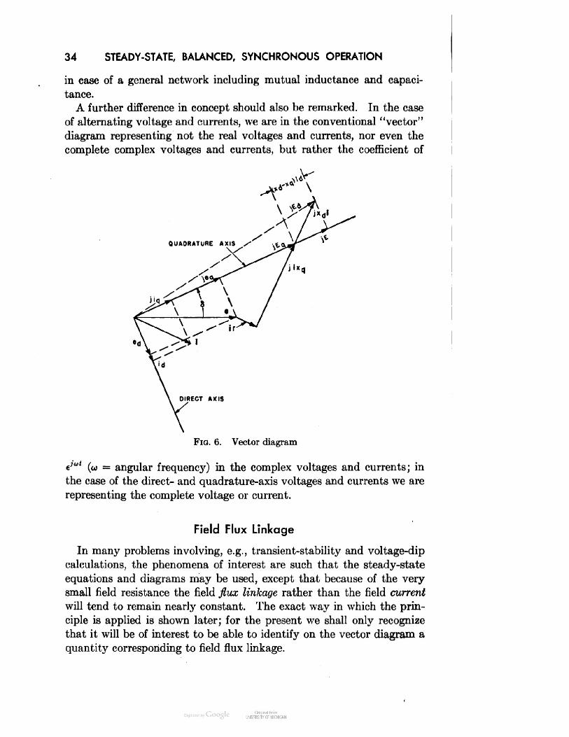
34STEADY-STATE, BALANCED, SYNCHRONOUS OPERATIONin case of a general network including mutual inductance and capaci-tance.A further difference in concept should also be remarked. In the caseof alternating voltage and currents, we are in the conventional "vector"diagram representing not the real voltages and currents, nor even thecomplete complex voltages and currents, but rather the coefficient of
Vector diagrame; (w = angular frequency) in the complex voltages and currents; inthe case of the direct- and quadrature-axis voltages and currents we arerepresenting the complete voltage or current.Field Flux LinkageIn many problems involving, e.g., transient-stability and voltage-dipcalculations, the phenomena of interest are such that the steady-stateequations and diagrams may be used, except that because of the verysmall field resistance the field flux linkage rather than the field currentwill tend to remain nearly constant. The exact way in which the prin-ciple is applied is shown later; for the present we shall only recognizethat it will be of interest to be able to identify on the vector diagram aquantity corresponding to field flux linkage.

FIELD FLUX LINKAGE 35Referring to equations 37, neglecting amortisseur currents we have^d = —Xdid + Xafdlfd(72)^/d = —Xafdid + XffdlfdEliminating the field current Ifd, we find, from the first equation 72:,,d. *+3* (73)-*a/d^ + (--S)«] ™and, from the second equation:Xffd*/d = —A-afdThe quantity,X afdXffdis a short-circuit reactance of the armature direct-axis circuit, whichwould be measured at the direct-axis armature terminals with zero fieldresistance. We defineXd — = x'd = transient reactanceXffdandXafdV'/d = E'q = voltage back of transient reactance (a quantity pro-iid portional to the field flux linkage)Then equation 74 becomesE'q = id + x'aid (75)or, sinceeq = ^d — riqtheneq = E'q — x'did — riq (76)Equation 76 is just like the second equation 56; so the whole of thederivation of the vector diagram may be repeated simply by substitut-ing x'd for Xd, and E'q for E, everywhere. [Note that now (x'd — xq)is negative.] The complete diagram, showing both E and E'q, is givenin Fig. 7.

36 STEADY-STATE, BALANCED, SYNCHRONOUS OPERATIONQUADRATURE AXIS
Fig. 7. Vector diagramWe may also find, from the second equation 72,rv Xafd , x2afd .E'q = —- frd = - —— id + EXlld X.ffdor, by the definition of x'd,E'q = E - (xd - x'd)id (77)This may be seen from Fig. 7 to check the value previously found.Power OutputThe power output of the machine is for balanced operation:P = edid + eqiq (78)If a dot product is defined, as for vectors, as the sum of the productsof the inphase components of two quantities e and i, then equation 78is equivalent toP = (ed + jeq) ■ (id + jiq) = e i (79)or, in another way,P = real part of [e times conjugate of i]

POWER-ANGLE CHARACTERISTICS 37Thus it is seen that even for the power equations the d, q axis quantitiese and i behave just like ordinary alternating voltages and currents. Ifresistance is neglected, it is further evident (equation 71) that jEq dif-fers from e only by a voltage drop having no components in phasewith i, and so the power output may also be written asP = (jEq).i (80)But, by equation 71,1-*^ TOSubstituting equation 81 in equation 80 gives/je \ Eqed EgeP = + (jEq) • (— )=-.- = — sin 5 (82)\Xq / Xq Xqwhere e is the magnitude of the terminal voltage as in equations 53.In using equation 82, it must be remembered that Eq does not in generalremain constant; instead either field flux linkage (or E'q) or field excita-tion (or E) may be taken as constant. The only object in presentingequations 79, 80, and 82 is to show ways of computing power whichmay be convenient when using either vector diagrams or an a-c networkanalyzer.Power-Angle CharacteristicsThe steady-state power-angle equation for zero armature resistanceand with fixed excitation has been given in equation 60 asEe /I 1 \ e2P = — sin 5 + ( --- ) - sin 25 (60)xd \z9 xd/ 2If the field flux linkage is assumed to remain constant, we may derivea similar transient power-angle characteristic in terms of the voltage E'q.We start, as in equations 54 but with r = 0, with(83)e =As before, tq — —xqiq, but now we use the newly derived relation 75,

38 STEADY-STATE, BALANCED, SYNCHRONOUS OPERATIONIt is now evident that the derivation proceeds exactly as before exceptthat we substitute E'q for E and x'd for Xd. The steps areed—Xqlqeq=E'q— x'didiq=edxqesin 5xqtE\~ HId=iidP=edd\ Vqlq ~and, finally,E'q — e cos 5Vded(E'q — eq) eqedX'd XqE'qe /1 1 \ e2P = —^ sin 5 + ( ) - sin 25 (84)xrd \xq x dt 2To see the form of these relations 60 and 84, we may take as a specificexample a machine having the constants:xd = 1.0(85)Xq = 0.6x'd = 0.3r = 0(these may be taken roughly as typical for a water-wheel generator) anda terminal voltage e = 1.0. First we consider the case of no-load ex-citation and field flux initially, so i = 0. By equation 71,Eq = 1.0By equation 68,E = 1.0and, by the similar equation,Eq = E'q - (x'd - xq)idE'q = 1.0(86)Thus the steady-state power-angle equation isP = 1.0 sin 8 + 0.333 sin 25 (87)The transient power-angle equation isP = 3.333 sin 5 - 0.833 sin 25 (88)

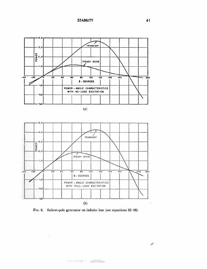
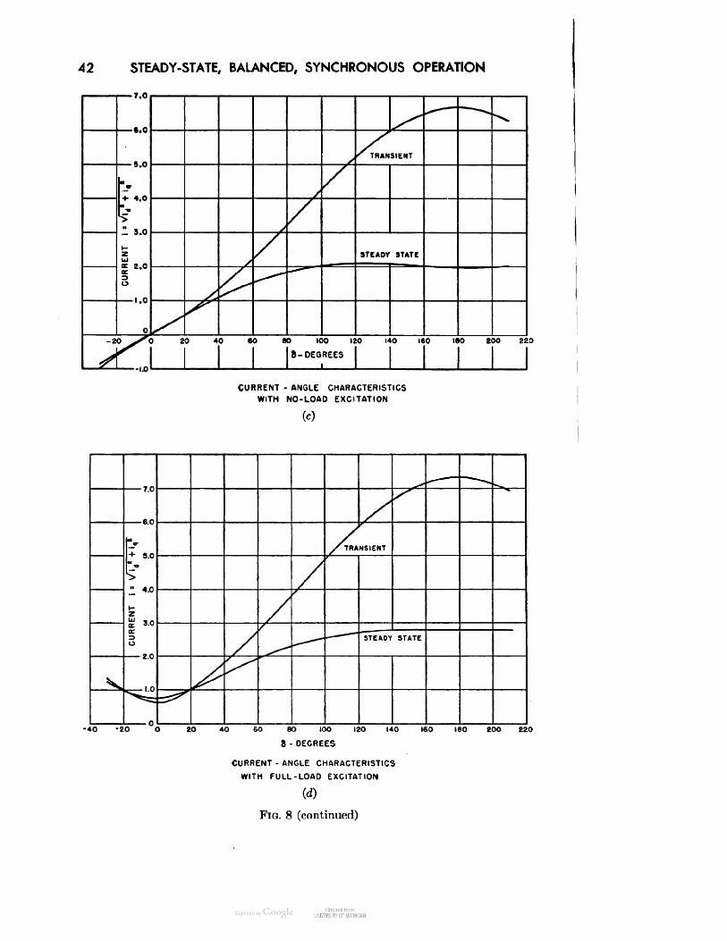
POWER-ANGLE CHARACTERISTICS 39Next we consider the case of full-load excitation and field flux ini-tially. As full load, we take unit current at 0.8 power factor, overexcited.[That is, the phase relation is such that (inductive) reactive power isconsumed by the system, so the required generator excitation is greaterthan for the same current at unity power factor. Similarly, we shalldefine a generator power factor as underexcited when (inductive) reac-tive volt-amperes are supplied by the system, so that the requiredgenerator excitation is smaller than for the same current at unity powerfactor.] Since only relative angles are essential in the vector diagram,we may takee = 1.0i = 0.8 - jO.6By equation 71,(jEq) = e + jxqi = 1.0 + jO.48 + 0.36orEq = | 1.36 + jO.48 | = 1.442By equation 68,E = Eq + (xd — xq)idwhere, from Fig. 6,= 1.442 + 0.4 sin (5 + <t>), 0.48 V5 = tan"1 = 19.4°1.36,0.64> = tan-1 — = 36.8°0.8sin (« + <*) = 0.832E = 1.774Similarly, by equation 86,E'q = 1.442 - 0.3(0.832) = 1.193Now the steady-state power-angle relation isP = 1.774 sin 5 + 0.333 sin 25 (89)and the transient power-angle relation isP = 3.977 sin 8 - 0.833 sin 25 (90)The powers for these four cases are plotted in Figs. 8a and 86. Thecorresponding armature currents i = V i2d + i2q (see paragraph fol-lowing equation 20) are plotted in Figs. 8c and 8d. The effect of saliency

40 STEADY-STATE, BALANCED, SYNCHRONOUS OPERATION(xq < xd) on torque is to introduce a second-harmonic term, the re-luctance torque, having its maximum at 5 = 45° into the steady-statepower-angle curve. Thus the maximum power occurs at an angle lyingbetween 45° and 90°, rather than right at 90° as in a symmetric-rotormachine.Similarly, the power-angle curve with fixed field flux linkage has asecond-harmonic term having its maximum at 5 = 135° since x'd < xq;so the transient power maximum occurs at an angle between 90° and135°.The angle at which maximum power occurs may be located by settingdP/d5 = 0. From equation 60,dP Ee (\ 1 \— = — cos 5 + ( I e2 cos 25 = 0 (91)dS Xd \xq xd/But cos 25 = 2 cos2 5 — 1, so equation 91 becomesxqE 1cos2 5 H cos 5 = 0 (92)2(xd - xq)e 2orxqE f xqE f 1cos 5= ±J +- (93)4(zd-x,)e \L4(zd-x,)eJ 2For usual values of the circuit parameters only the positive value of theradical, giving 5 < 90°, will correspond to maximum power, the otherroot being greater than 1.0. The same analysis can be carried throughfor constant field flux, leading to(94)4(*9 — x'd)e \ L4(x, — x'das the desired root.StabilityIn the actual operation of a synchronous generator connected to alarge power system, the power input is controlled by the prime mover,waterwheel, steam turbine, etc., and the rotor angle 5 will tend toadvance until the power output, as given by the steady-state curves ofFig. 8, equals the input (minus the losses which we have so far neglected).If the prime-mover input becomes too large, or, as is much more likely,if the equivalent system impedance (which we have seen may be addeddirectly to the armature reactance and resistance) becomes too largebecause of changes in the system, e.g., following the switching out of afaulted line, the maximum power output may be smaller than the input.
STABILITY41
(a)
Fig. 8. Salient-pole generator on infinite bus (see equations 85-98)
42 STEADY-STATE, BALANCED, SYNCHRONOUS OPERATIONSTEADY STATE20 40 6080 100 120 140 160 ISO ZOO 220I 8-DEGREESCURRENT - ANGLE CHARACTERISTICSWITH NO-LOAD EXCITATION(c)STEADY STATE-40 -20 O 20 40 60 80 IOO 120 140 160 160 20O 2208- DEGREESCURRENT . ANGLE CHARACTERISTICSWITH FULL-LOAD EXCITATIONtoFIG. 8 (continued)

STABILITY43
(e)
(/)Fig. 8 (continued)
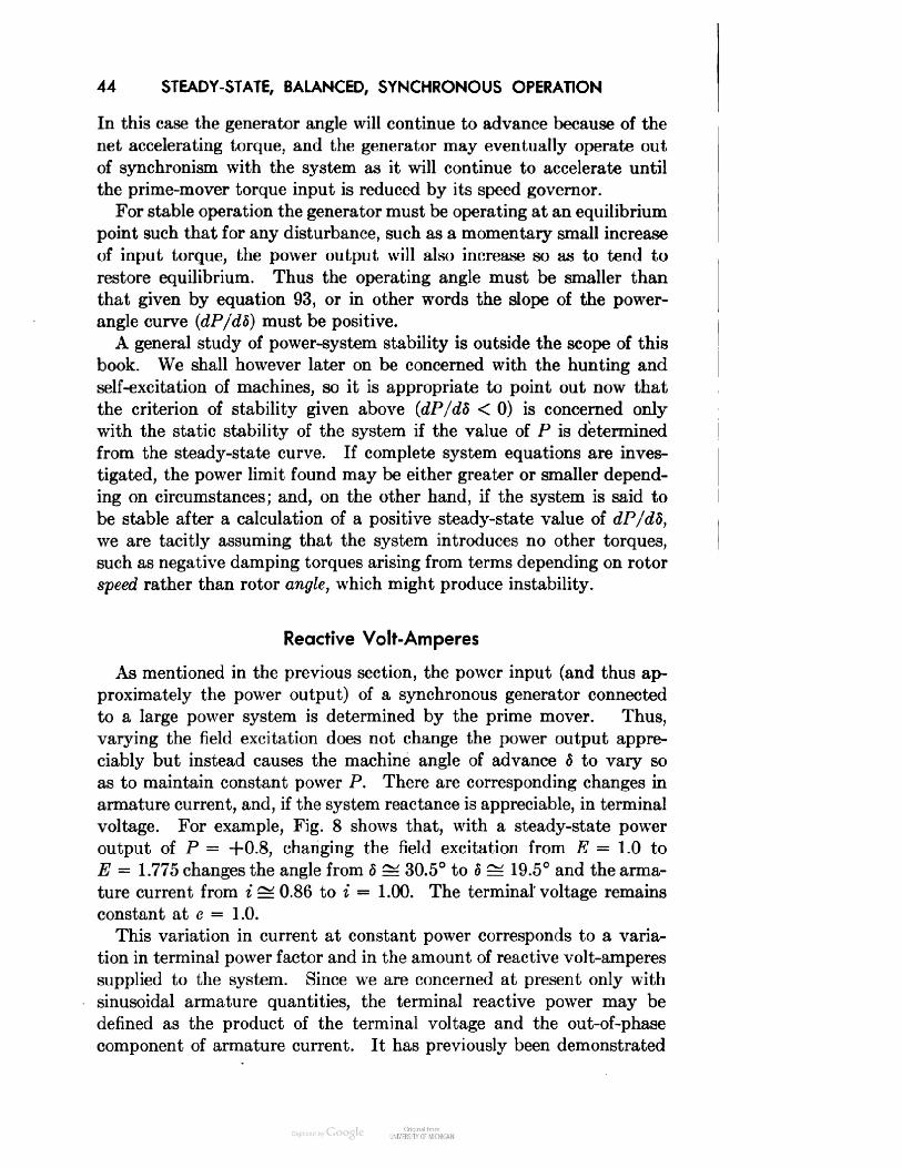
44 STEADY-STATE, BALANCED, SYNCHRONOUS OPERATIONIn this case the generator angle will continue to advance because of thenet accelerating torque, and the generator may eventually operate outof synchronism with the system as it will continue to accelerate untilthe prime-mover torque input is reduced by its speed governor.For stable operation the generator must be operating at an equilibriumpoint such that for any disturbance, such as a momentary small increaseof input torque, the power output will also increase so as to tend torestore equilibrium. Thus the operating angle must be smaller thanthat given by equation 93, or in other words the slope of the power-angle curve (dP/dS) must be positive.A general study of power-system stability is outside the scope of thisbook. We shall however later on be concerned with the hunting andself-excitation of machines, so it is appropriate to point out now thatthe criterion of stability given above (dP/d5 < 0) is concerned onlywith the static stability of the system if the value of P is determinedfrom the steady-state curve. If complete system equations are inves-tigated, the power limit found may be either greater or smaller depend-ing on circumstances; and, on the other hand, if the system is said tobe stable after a calculation of a positive steady-state value of dP/dS,we are tacitly assuming that the system introduces no other torques,such as negative damping torques arising from terms depending on rotorspeed rather than rotor angle, which might produce instability.Reactive Volt-AmperesAs mentioned in the previous section, the power input (and thus ap-proximately the power output) of a synchronous generator connectedto a large power system is determined by the prime mover. Thus,varying the field excitation does not change the power output appre-ciably but instead causes the machine angle of advance 5 to vary soas to maintain constant power P. There are corresponding changes inarmature current, and, if the system reactance is appreciable, in terminalvoltage. For example, Fig. 8 shows that, with a steady-state poweroutput of P = +0.8, changing the field excitation from E = 1.0 toE = 1.775 changes the angle from S ^ 30.5° to 5 ^ 19.5° and the arma-ture current from i ^ 0.86 to i = 1.00. The terminal voltage remainsconstant at e = 1.0.This variation in current at constant power corresponds to a varia-tion in terminal power factor and in the amount of reactive volt-amperessupplied to the system. Since we are concerned at present only withsinusoidal armature quantities, the terminal reactive power may bedefined as the product of the terminal voltage and the out-of-phasecomponent of armature current. It has previously been demonstrated

REACTIVE VOLT-AMPERES 45that the phase displacement between voltage and current is the samefor the direct- and quadrature-axis quantities as for the phase quantities,so reactive power may be defined similarly to real power (equation 79) asQ = e (ji) = (ed + jeq) • (jid - *9)(95)The last form of equation 95 shows also that the reactive power maybe regarded asQ = imaginary part of [e times conjugate of i] (96)Thus we may writeei* = (e.d + jeq)(id - jiq) = P+jQ (97)This shows also thatVP2 + Q2 = | e I | i | (98)as should of course be true for any valid definition of reactive power.The first form of equation 95, Q = e. (ji), is believed to be the mostgenerally useful and fundamental definition. This definition correspondsin fact to the usual way in which reactive power is measured, that is,by means of a wattmeter with either its current or voltage input shiftedby 90°. Note that our definition (i.e., shifting the current ahead by90°) means that an overexcited generator will tend to supply positivereactive power to the connected system.Figures 8e and 8/ show the variation of reactive volt-amperes withangle for fixed excitation and for fixed field flux as discussed previously.In these cases, since | i \ and P have already been calculated and e isunity, the magnitude of Q is most simply found from equation 98. Thesign however must be determined from the relative phase positions ofe and i. If i lags e in our vector diagram, Q is positive.By substituting equations 53 and 67 into the last form of equation 95,we may find an expression for reactive power Q at the infinite bus directlyin terms of excitation and angle:Ee /I 1 \ e2 / 1 1 \ e2Q = — cos 5 - (— + —)- + ( ) - cos 25 (99)xd \xg Xd/ 2 \xq Xd/ 2This is in a form similar to equation 60 for the power P. It is not how-ever practical in case of a salient-pole machine to use equations 99 and60 directly to solve for Q as the excitation E is varied, with constant P.Instead, we must assume an angle 5, calculate E from equation 60 fora given P, and then Q from equations 99 or 95 for this angle. Equa-tion 99 is only for calculating the reactive power at the infinite bus e,
46 STEADY-STATE, BALANCED, SYNCHRONOUS OPERATIONor for the case of negligible system reactance. If the system reactanceis appreciable, then terminal voltage and armature current must be com-puted and equation 95 used to obtain the reactive power.As another kind of application of these relations, we shall determinethe maximum reactive-volt-ampere-absorbing capacity of a synchronouscondenser connected to a large power system. Here, neglecting all losses,the power is zero so that 5 = 0, but, on the other hand, since the con-denser must operate stably, dP/dS must be equal to or greater thanzero. Consideration of equation 60 or of the form of the power-anglecurves shows us that the second-harmonic, or reluctance-torque, termremains constant as excitation is varied and that E may become nega-tive. Equation 91 may be solved for E, with S = 0, to obtain#min = I 1 -- ]e (100)\ Xq/and, from equation 99, 2Qmin - - - (101)XqNote that if negative excitation could not be used the minimum Q wouldbe only —e2/Xd.Power-Angle Characteristics for Two MachinesIn this section we shall derive an expression for the power or torquefor a salient-pole synchronous generator supplying power to a salient-pole synchronous motor. This will be done not merely as an algebraicexercise, but rather to show how the interconnection of two synchronousmachines may be made in terms of direct- and quadrature-axis quantities.The generator and motor will be called machines 1 and 2, respectively,and subscripts will be used accordingly.The terminal voltage relations areebl = eb2 (102)eci = ec2The armature current relations are*ol = ~ia2ibi = -ibt, (103)id — ~ic2The angle relation is01 = S + 02 (104)

POWER-ANGLE CHARACTERISTICS FOR TWO MACHINES47Now equations 35 and 33 are substituted into equations 102 and 103,respectively. Whence, after some manipulation, we obtain(a)(b)(c)(d)(e)(f)(g)(h)(i)(j)edi = +ed2 cos 5 + e,2 sin 5e,i = — ed2 sin S + e,2 cos SCOs S — cqi sin 5sin A + e,i cos 5idi = —id2 cos 8 — • i,2 sin Siqi = +id2 sin 5 — iq2 cos 5id2 = — idi cos 5 + i,i sin 51,2 = —idi sin 6 — iqi cos 5(105)The relations 105 may also be derived directly from Fig. 9 since theform as well as the derivation of the ed and eq relations 28 and of thed -AXIS OF MACH I
FIG. 9. Terminal-voltage relations for two machinesid and iq relations 20 show that they may be regarded as projectionsof the magnitudes of ea, e6, ec, ia, ib, ic, on mutually perpendicular dand q axes for the two machines, if ea, e\,, etc., are plotted along threeequally spaced a, b, c axes common to the two machines.

48 STEADY-STATE, BALANCED, SYNCHRONOUS OPERATIONIn the steady state with zero armature resistance (r = 0) and atsynchronous speed (p6 = 1.0), for either machine,ed = -tq = +xqiqand (106)eq = +td = E — xdidThen from equations 105a and b, we findXqiiqi = Xq2iq2 cos 5 + (E2 — Xd2id2) sin 5El — Xdiidi = —Xq2iq2 sin 5 + (E2 — xdtf.dt) cos 5Substituting equations 105g and h in the last two equations, and rear-ranging and combining terms, we findXd2 — Xq2 .— idi sm 25A/ *£d2 i* Xg2 *£(12 •^o2 \+ iqi { Xqi H cos 25 I = E2 sin 5\ 2 2 // . x (107)/ a'(i2 T Xg2 Xd2 Xq2 \+ ldl [ Xdl H i COS 25 IV 2 2 /— iqi —— —— sin 25 = El — E2 cos 5from whichEi[xqi + \(xd2 + xq2) — %(xd2 — xg2) cos 25] — E2(xqi + xq2) cos 5(108)- Xq2) sin 25 + E2fadi + ^ sin 5whereA =- \(xdi - xql)(xd2 - xg2) cos 25 (109)The power may be found from P = ediidi + eqiiqi, or, from equation 106,P = Eliql — (Xdl - Xql)idliql (110)Substituting equation 108 in equation 110, we find the final expressionfor power:i - xgl)(xd2 - xq2)] sin 5+ Xqi) + E22(xdi - Xqi)(xdi + xq2)] sin 252(xdi - xql)(xd2 - xq2) sin 35} -H A2 (111)where A is given by equation 109.

POWER-ANGLE CHARACTERISTICS FOR TWO MACHINES49It should be evident how expressions similar to equation 111 can befound for the condition of constant field flux linkage in either or bothof the two machines.Figure 10 shows plots of steady-state and transient power, current,and terminal voltage for two equal machines, each having the constantsof equation 85, Xdi = xd2 = 1.0, xqi = xq2 = 0.6, and for the two con-ditions of no-load excitation (Ei = E2 = 1.0) and of full-load, unity-power-factor excitation. The full-load excitation is found by takingfor initial condition the terminal voltage and armature current in phaseand both equal to unity. Then, from equation 71 or Fig. 6,Eq = | 1.0 + j'0.6 | = 1.166(tx \tan-1—-J = 0.513^term /Ex = E2 = Eq + id(xd - xq) = 1.371
(a) Power-angle characteristics with no-load excitations
(6) Power-angle characteristics with full-load excitationsFig. 10. Two salient-pole machines (see equations 85 and 106-111)

50 STEADY-STATE, BALANCED, SYNCHRONOUS OPERATION— 3.5TRANSIENT1 COl-2I11DC5 ..5uSTEADY STATE20 40 60 80 I00 I20 I40 I60 I60 200 2208 - DEGREES(c) Current-angle characteristics with no-load excitations
20 40 60 80 I00 I20 I40 I60 I80 200 2208 - DECREES(d) Current-angle characteristics with full-load excitationsFig. 10 (continued)
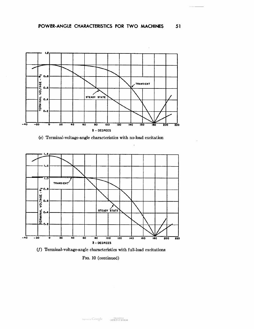
POWER-ANGLE CHARACTERISTICS FOR TWO MACHINES 51X-TSTEADY STATE\0 20 40 60 60 100 120 140 160 180 200 2208 - DEGREESTerminal-voltage-angle characteristics with no-load excitation,^— ^sX^N\*-rt.BTRANSIENT'X^{TERMINAL VOLTAGE •e\0 O Or* * o>STEADY STATEDV\\N\\/0-20 0 20 40 60 80 100 120 140 160 180 200 22C8 - DEGREESN\\/•(/) Terminal-voltage-angle characteristics with full-load excitationsFIG. 10 (continued)
52 STEADY-STATE, BALANCED, SYNCHRONOUS OPERATIONSummaryIn this chapter we have shown how the conventional vector diagramof a-c circuit analysis may be applied to the synchronous-machine quan-tities, even though the latter are d-c quantities. We have found itconvenient to introduce a construction voltage Eq back of xq and havepointed out that use of this voltage may be desirable when setting casesinvolving salient-pole machines on the a-c network analyzer. As aspecific application, and largely to show the effect of saliency as dis-tinguished from round-rotor theory, we have computed several torque-or power-angle characteristics. These characteristics have also broughtto our attention the fundamental problem of securing stable operation.It has further been observed that a synchronous machine supplies notonly power but reactive volt-amperes to the system to which it is con-nected, and that the amount of the reactive volt-amperes is largelydetermined by the amount of machine field excitation.In the next chapter we shall begin the discussion of short-circuitcurrents.Problems1. For a synchronous machine having the characteristics:Xd = 1.3 puxq = 1.25x'd = 0.17r = 0.01and operating under the conditions,e = terminal voltage = 1.0111 = magnitude of armature current = 1.0plot the per unit values of the field flux linkage E'q and of the field excitation Eas functions of load power factor. These machine characteristics may be repre-sentative of a turbine generator.2. Repeat the calculations of problem 1 for the machine characteristics:Xd = 1.0 puxq = 0.6x'd = 0.3r = 0.01These machine characteristics may be representative of a salient-pole water-wheel generator.
PROBLEMS 53Compare the values of field flux linkage and of machine angle found in thesetwo problems.3. Consider the synchronous machine of problem 2 connected to an infinitebus through a reactance of xe = 0.25 p u on the machine base. The machineterminal voltage is unity, the power is 0.5 p u. With the field excitation re-duced, and the infinite bus voltage correspondingly raised so as to maintain unitterminal voltage, until the machine is operating at its steady-state stabilitylimit, calculate the field current E< the field flux linkage E'q, and the reactivepower at the machine terminals. Neglect armature resistance.

4 THREE-PHASESHORT-CIRCUIT CURRENTIt is necessary to understand the nature of the short-circuit currentsof synchronous machines, particularly for large machines, in order toapply proper relaying and switchgear and to evaluate the windingstresses and shaft torques incident to short circuits. In a large powersystem, there may be considerable interaction and swinging among thevarious machines following a severe system short circuit, and there maybe voltage-regulator action. So we must regard the analysis now to bepresented merely as a necessary beginning for a more complete study.For the study of whole systems, each machine cannot be treated indetail, but, before we can use the conventional approximations intelli-gently and confidently, we must know what we are missing. For thisreason we consider first a three-phase short circuit at the terminals ofa single synchronous machine.Consider a synchronous generator initially operating at balanced loadand running at rated speed w (w = 1). The terminal voltages will be(see equations 53)Sd = ed0 = e sin 6, eg = eqQ = e cos 5, e0 = 0To find the short-circuit currents, we apply unit-function terminal volt-ages equal and opposite to those existing before the short circuit. Thusequations 32 become— ed0l = —e sin 51p\l/q — rig + i/yw = — eg0l = — e cos 51 (112)pt0 — n'0 = 0The currents and flux linkages in equations 112 are only the componentscaused by the short circuit, and the currents found from these equationsmust be added to the initial load current to find the total current. Sincewe are concerned only with the changes of flux linkage, and since weshall assume constant excitation (or no voltage-regulator action), equa-tions 36 becometd = -xd(p)id, tq = -xq(p)iq, t0 = 0 (113)54

THREE-PHASE SHORT-CIRCUIT CURRENT 55It is evident from equation 112 that no zero-sequence effects are pro-duced by simultaneous short circuit of all three phases, and so we needconsider only the direct- and quadrature-axis equations.By equations 113 in 112,r]id — uxq(j>)i(114)[pxq(p) + r]iq =whence. _ [pxq(p) + r]eM +[pxd(p) + r][pxq(p) + r] + <a2xd(p)xq(p)(115)- uxd(p)ed0[pxd(p) + r][pxq(p) +r]+ u2xd(p)xq(p)The solution of these equations is straightforward but extremely com-plicated, as they may be of a very high degree in the differential oper-ator p. It will therefore be of interest to examine the nature of thesolution from a physical point of view and thereby to arrive at a rea-sonably simple formula.First, in order to show the degree of the equation, we consider a spe-cific case in which the machine has one rotor circuit in each axis in addi-tion to the field. Then from equations 39, with I2d = hd (etc.) = 0,and substituting for tfd and \l/id from equations 37, we find, for thefield and direct-axis amortisseur currents,*Ifd = - - — - - (116)Tlid = - — — - (117)A(p)where A(p) = p2(xndxffd - x2fid) + p(xndRfd + xffdRid) + RuRfd.Substituting equations 116 and 117 in the first equation 37 for \l/d, wefindP(XlidXafd — XfidXald) + XafdRldefdA(p)itr^afdRld + X2aldRfd) >7—7 *d (H8)A(p)* Note that in these equations, as in all the rest of this book, only the reciprocalsystem of inductance coefficients is used, but we have returned to the use of lowercase x's, as remarked in Chapter 2.

56 THREE-PHASE SHORT-CIRCUIT CURRENTBy comparing equation 118 with the first equation 36, it becomes evi-dent that_ _ p(XlldXafd - XfidXaid) + X«f _2 2 P(XlldRfd(120)Similarly, for the quadrature axis, we may start from equations 40 (withI2q = Izq = 0) ar>d equation 38. The final expression for the quadra-ture-axis operational impedance is*9<P) = *9 -- PXo1g (121)Now returning to the operational expression 115 for the short-circuitcurrents id and iq, we can see, by substituting equations 120 and 121for Xd(p) and xq(p), respectively, that the solution requires finding theroots of a fifth-degree polynomial in p. We observe further that ifarmature resistance is neglected (r = 0) the common denominator ofequations 115 immediately reduces to(p2 + u?)xd(p)xq(p)the roots of which can be found by solving two quadratic equations andone linear equation. Neglecting armature resistance means that thefluxes linking the armature circuits cannot change from their initialvalues after the short circuit occurs (see equations 1) so that there isa d-c flux (and a corresponding direct current) in the armature thatnever decays. The actual current will be smaller than the current sofound. The short-circuit currents may be written as(122)(P2 + o,To find an upper limit for the current, we may also at first neglect allrotor resistances. In this case, equations 120 and 121 lead to

THREE-PHASE SHORT-CIRCUIT CURRENT 57Xd(p) = X"d = Zd(°o)2— X fx2= X"q = !,(«) = Xq - -i-* (124)Equations 120 and 121 show that neglecting rotor resistance is the sameas taking p = », and this in turn shows that we are computing initialvalues, since taking p — » in the notation of operational calculus cor-responds to taking initial values of a function. Indeed, without drag-ging in the mathematical notation at all, we may find it very plausibleto believe that by neglecting all resistances we can compute initial valuesof current, since with zero resistance the fluxes linking every circuitremain constant, as they do at the first instant even with resistance.10The actual short-circuit current may thus be expected to tend at firstto follow a course given by equation 1 15 with Xd(p) = x"d, xq(p) = x"a,but gradually to deviate from this value and decay eventually to afinal steady-state value obtainable by putting p = 0 in equation 115or by using the steady-state equations directly.We definex"d = direct-axis subtransient reactancex"q = quadrature-axis subtransient reactanceThe name "subtransient" is used in order to distinguish these reactancesfrom the transient reactances, which are defined in the same way exceptthat the presence of amortisseur windings is ignored. Historically, themachine without amortisseur was analyzed first and the name "tran-sient" appropriated for that case.From equations 122, with xd(p) = x"d and xq(p) = x"q, and with<o = 1.0,td0 . e,nid = — sin t + — (1 - cos 0x d x deg0 , «d0iq = — sin t -- — (1 - COS 0X q X qor since (equations 53)ed0 = e sin 5, e90 = e cos 5eid = -- [cos 5 — cos (< + 6)]x" d(125)eiq = -~ — [sin S — sin (< + 5)]

58 THREE-PHASE SHORT-CIRCUIT CURRENTBy equations 33, the current in phase a isia = id cos (t +00) - iq sin (t + 00) (126)or1 1 \e / 1 1 \ e2 2d X q/ Z \X d X q/ £iX [cos (t + 00 + 5) - cos (2< + 00 + 5)] (127)The currents in phases 6 and c are obtainable by replacing 60 by(60 - 120°) and (00 + 120°), respectively.For no load initially, 5 = 0 and ia reduces toe / 1 1 \ eia = — COS (t + 60) ~ ( — + — ) - COS 6QX d ^^ d <£ *"cos(2'+w (128)For short circuit from no load, equation 128 shows that the initialarmature current is composed of a fundamental-frequency componentdepending only on x"d, a d-c component depending on an average ofx"q and x"d, and a small double-frequency component depending on thedifference between x"d and x"q (the subtransient saliency).As the other extreme we may take the case of short circuit from asteady-state load with 5 = 90°. It must be remembered however thatthis may be an unstable condition and is considered only to show thelimiting formula for short-circuit current. For 5 = 90°, equation 127becomes1 \e7rjoq/ &I 1 \e--- ^)-sin(2<-r.00) (129)X d X q/ 2The principal effect of initial load angle is seen to be to make the funda-mental component of short-circuit current depend on x"q rather thanon x"d as in the no-load (S = 0°) case. This point is mentioned becausethere has been some tendency to assume that short-circuit current alwaysdepends principally on the direct-axis machine constants.Synchronizing CurrentsAnother application of equation 127 for an even greater effective angle Bmay arise in synchronizing a generator. In this case let us assume that

STEADY-STATE COMPONENTS OF SHORT-CIRCUIT CURRENT 59the machine is running at synchronous speed at an angle S0 ahead ofthe bus voltage. Then the machine voltages areegm = E, edm = 0and the bus voltages areeqb = e cos 5o, edb = e sin S0When the machine terminals are connected to the bus, the resultingcurrents are as before found by the application of voltages equal andopposite to those existing across the open switch. These voltages areC,O = tqm — tqb = E — e COS S0ed0 = edm — edb = — e sin S0Now eq0 is likely to be smaller than ed0, and ed0 may equally probablybe either positive or negative; so the effective angle may be very largein either direction. Since both voltages will usually be rather smallfor a proper synchronization procedure the currents will also be rela-tively small. However, it is evident that synchronizing with an infinitebus out of phase may in the limit (at SQ = 180°) be equivalent to shortcircuit from double voltage. On the other hand, it should be furtherevident that, if the bus or system to which the machine is being syn-chronized has a reactance equal to or greater than the direct-axis sub-transient reactance of the machine, the maximum current will not exceedthe three-phase short-circuit current.Steady-State Components of Short-Circuit CurrentIn the steady state, from equation 115 with p = 0, and w = 1.0,re sin 5 + xqe cos 5id = a~ir" + xdxq(130)re cos 8 — xde sin 5r2 + xdxqThe current in phase a ise [ Xd + xqia = -y ~r sin (t + 60 - 8) H cos (t + 60 - 8)r2 + xdxq L 2- — — cos (t + 00 + 8) (131)2 J

60 THREE-PHASE SHORT-CIRCUIT CURRENTFor 5 = 0,ia = -5 - [~r sin (t + 00) + xq cos (t + 00)] (132)r + xdxqFor r = 0 but 6 ^ 0,e IV 1 1\ / 1 1\ Iia = - ( - + - cos (t + 60 - 5) + I --- ) cos (t + 60 + 5)2 l\Xd Xq/ \Xd Xq/ I(133The steady-state current is all of fundamental frequency and for zeroarmature resistance is obtainable by replacing Xd(,x>) by £,j(0) and xq(&>)by xq(0) in the fundamental-frequency terms of the initial-current equa-tion 120. We should note that these formulas for steady-state currentgive only the component produced by the application of a terminalvoltage equal and opposite to that existing before the short circuit.Actually, in the steady state this whole component is exactly canceledout by the corresponding components of load current produced by theterminal voltage, leaving only the component of load current producedby field excitation. Thus, as we should naturally expect, there is noevidence of the angle 5 in the total steady-state short-circuit current.This total current can be computed simply by taking 5 = 0 and e = Ein equations 130-133, or by setting e = 0 in equations 58 of Chapter 2.For the present, however, we are interested only in the componentsproduced by short circuit, since our object is to arrive at some idea ofthe course of this current as a function of time.First we note that the d-c and double-frequency components of thephase current ia disappear completely. Both of these components arederived from the fundamental-frequency components of id and iq, so itis evident that they must have the same rate of decay.Both of these components arise from the flux which is trapped inthe armature circuits at the instant of short circuit. This flux graduallydecays to zero and, considered as approximately constant, generatesfundamental- (i.e., rotational-) frequency currents and fluxes in all therotor circuits. It therefore seems reasonable that the decay of the d-ccomponent may be computed by considering only the armature resist-ance, since the rotor resistances may be negligible in comparison to theirreactances at fundamental frequency. We may refer back to equations115 and now find the roots of the common denominator of id and iq:r)(x"qp + r) + x"dx"q
STEADY-STATE COMPONENTS OF SHORT-CIRCUIT CURRENT 61The roots of equation 134 are •The frequency is practically unity, and the time constant iso*." »"ix dx qTa3 = r(r» 4. r" \f\f d T X q)(136)and is the ratio of the average (i.e., as should be expected, the samekind of average that is effective in determining the magnitude of thed-c component according to equations 127 or 128) armature short-cir-cuit inductance to the armature resistance. This approximation hasbeen justified not only by comparison with actual short-circuit testsbut also by the mathematical analysis of several cases including allresistances."In a similar way the decay of the transient part of the fundamental-frequency component of phase current corresponds to the decay of fluxlinking the rotor circuits and may be approximated by examining thecase of zero armature resistance. From equations 122 it is evident thatthere is a purely sinusoidal component of id and iq corresponding to thefactor (p2 + 1) (i.e., u = 1.0) in the denominator and to the decayingterm discussed in the previous paragraph. This component may nowbe disregarded and our attention turned to the terms arising from thefactors Xd(p) and xq(p)< which determine the decay of the d-c componentsof id and iq.In the case of iq, from equation 121,, . gg ag qqxq(p) = - -r- (137)XUqP + KlqThis gives, as the time constant of the decaying component of iq,X alq2 ~X alq_,„1 93 =XqRlq RigX2alq»JLrj.r v"XiIqX qThe last form of equation 138 shows that the effective quadrature-axisrotor time constant for a three-phase short circuit is the time constant

62 THREE-PHASE SHORT-CIRCUIT CURRENTof the quadrature-axis amortisseur coil considered by itself, multipliedby the ratio of subtransient to synchronous quadrature-axis reactance.The second form of equation 138 shows that it may also be founddirectly from the short-circuit reactance viewed from the amortisseurcircuit.In the case of id, Xd(p) contains the second power of p so that it wouldseem that a quadratic equation must be solved. However, considerationof the magnitudes involved permits a considerable simplification. Thatis, the amortisseur resistance is usually very high in comparison to thefield winding resistance. For example, the ratio may be of the orderof 50. Thus it is permissible to calculate the rapid decay of amortisseurflux on the assumption of zero field resistance, and the slow decay offield flux on the basis of infinite amortisseur resistance, that is, with theamortisseur open-circuited. On making each of these two assumptionsin turn, we need only solve a first-order equation in p in each case.From equation 120, with Rid = °°, we find, for the direct-axis transientor field time constant,X afdKfdWith Rfd = 0, the subtransient or amortisseur time constant is, fromequation 120,Xd(XndXffd -daX2fidRid X'd040)The fundamental-frequency component of armature current arisingfrom id thus decays in two stages, first rapidly from its initial sub-transient value as determined by x"d to a transient value determined bythe transient reactance x'd [calculated 'from Xd(p) with zero field resist-ance but without consideration of the amortisseur], and then moreslowly from the transient value to the steady-state value as determinedby Xd. The fact that the intermediate or transient value of id is deter-mined by x'd may be seen from equation 75 of Chapter 3 and the accom-panying argument, in which it is shown that, for the condition of con-stant field flux linkages instead of constant field current, x'd replaces Xd.From the mathematical point of view, equations 139 and 140 are to
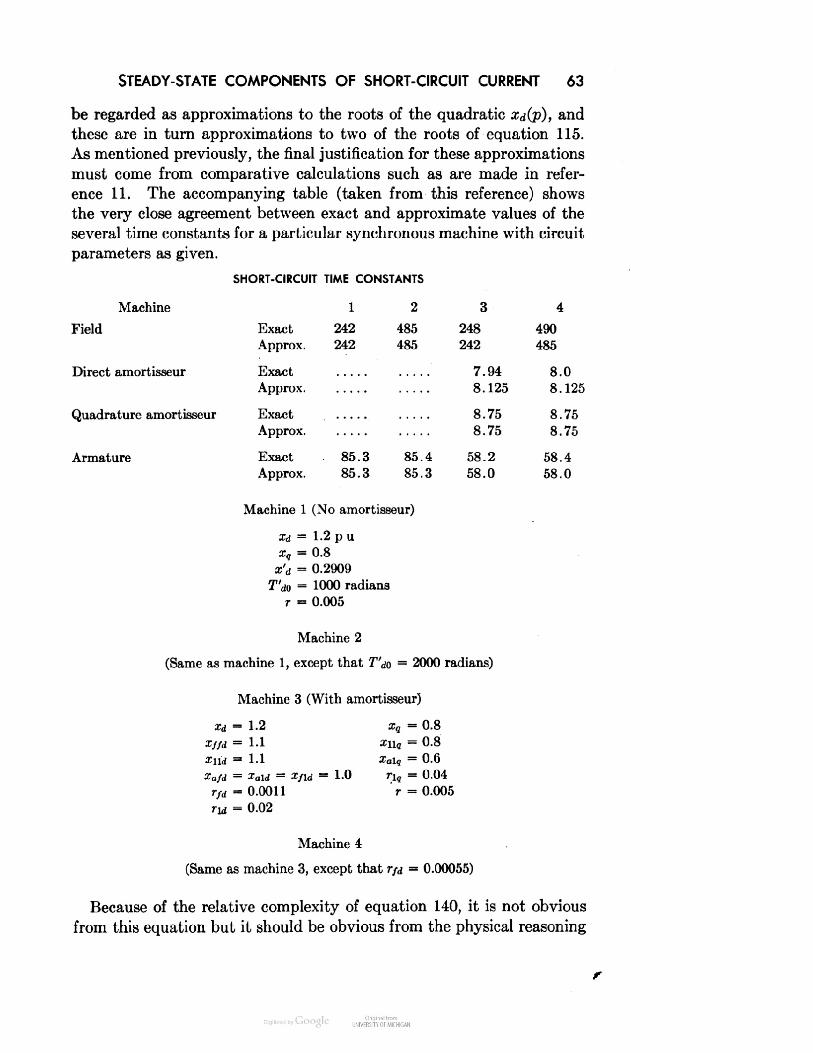
STEADY-STATE COMPONENTS OF SHORT-CIRCUIT CURRENT 63be regarded as approximations to the roots of the quadratic Xd(p), andthese are in turn approximations to two of the roots of equation 115.As mentioned previously, the final justification for these approximationsmust come from comparative calculations such as are made in refer-ence 11. The accompanying table (taken from this reference) showsthe very close agreement between exact and approximate values of theseveral time constants for a particular synchronous machine with circuitparameters as given.SHORT-CIRCUIT TIME CONSTANTSMachine1234FieldExactApprox.242242485485248242490485Direct amortisseurExactApprox.7.948.1258.08.125Quadrature amortisseurExactApprox.8.758.758.758.75ArmatureExactApprox.85.385.385.485.358.258.058.458.0Machine 1 (No amortisseur)id = 1.2 p uxq = 0.8x'd = 0.2909T'do = 1000 radiansr = 0.005Machine 2ame as machine 1, except that T'do = 2000 radians)Machine 3 (With amortisseur)xd - 1.2Xq = 0.8Xffd = 1.1zii, = 0.8Xnd = 1.1Xalq = 0.6Xafd = Xald = XfU =1.0rig = 0.04rfd - 0.0011r = 0.005rU = 0.02Machine 4(Same as machine 3, except that rfd = 0.00055)Because of the relative complexity of equation 140, it is not obviousfrom this equation but it should be obvious from the physical reasoning

64 THREE-PHASE SHORT-CIRCUIT CURRENTleading up to it that T"d3 is simply the ratio of the short-circuit react-ance viewed from the direct-axis amortisseur circuit to its resistance.Later, equivalent circuits for the direct- and quadrature-axis operationalimpedances will be given, and these will aid in simplifying the numericalwork of calculating the various reactances required.We may define so-called open-circuit (that is, the armature is open-circuited) rotor time constants asq0(141)Xndwhence equations 138-140 becomemiqOx"qn _ mil _ *3 — 1 O ~~XT'd3=T''l0 — (142)xdr",mi _ T"1 d3 — 1 *) —x'dSimilar relations for other types of short circuit are derived later, sothat the necessary time constants for any short-circuit case can be con-veniently obtained from the open-circuit values.Finally, from the various time constants discussed previously, theapproximate expression for the short-circuit current is- — e-t/Ta>e cos (t + S) (143)X"diq = _ 17 J_ - -) e-t/T"'> + -] e sin S + ~ rl/T°>e sin (t + S)L \X q ZCq/ Xq J »C qThis is the current for short circuit from any load condition, but withsmall armature resistance. It is the component produced by the suddendisappearance of the terminal voltage e and does not include the original

STEADY-STATE COMPONENTS OF SHORT-CIRCUIT CURRENT 65load components, which are, from equations 58 with r = 0,E — e cos 6(144)esm S•'9Adding equations 144 and 143, we find the total current, including theload current, to beEH — «T'/r" e cos (t + &) , (145)iq = - f— ) e~'/T"^e sin & + — e~'/r"e sin (t + 5)\X q 2Cq/ X gUnder the assumption that T"d3 and T"g3 are much smaller thanand in view of the method of derivation of these approximate re-sults, it is evident that the fundamental component of armature currentia (which corresponds to the constant and exponentially decaying com-ponents of id and iq) has at first a value determined with all rotorresistances zero (that is, with flux linkages constant in all rotor circuits),then a value determined by neglecting the amortisseur circuits and thefield resistance (that is, with field flux linkage constant), and finally thesteady-state value.Similarly, the d-c component of armature current ia consists of asingle exponentially decaying term determined by an average short-circuit reactance.As a check from a somewhat different point of view on the magnitudeof the transient component of short-circuit current as determined bythe condition of constant field flux linkage we may compute the ratioof transient to steady-state current from equation 145 and show thatit is exactly equal to the ratio of initial to final field flux linkage, as itshould be. From equation 145,E ( 1 1\h I — 1 e cos 5Id (transient) Xd \X d Xd'Id (steady state) EXdd \e cos 8-1) - (1450)'d )x'd E

66 THREE-PHASE SHORT-CIRCUIT CURRENTFrom the second equation 37, the initial field flux linkage under load is— Xafdid(E — e COS 5\ fx'd\ Xafd- ) = ( — 1 Xffjifd H -- e cos 5Xd / \Xd/ XdXdand the final field flux linkage is.Yfdf = Xffdlfd — Xafd ( — ) = I — 1 Xffjlfd\Xd/ \Xd/whencetfdi _ xafde cos 5COS 5= (145a) (1456)When decrements are included as in equation 145, it is not possibleto reduce the expression for the phase current ia to as simple a formas equation 127. It is correspondingly difficult to determine the machineconstants from a short-circuit test starting from load. However, ashort-circuit test from no load forms a convenient way of determiningthe direct-axis machine characteristics. For this case 5 = 0 and E = e,and ia becomes* = [(4- - 4-) ,-"'"*+(4. -l\x"d x'd/ \x'd xd Xd/ Xdee-i/r03n/j_< _LJ\ 0 vj i(146)The two other phase currents *6 and ic are similar, but with 00 re-placed by 00 - 120° and 00 + 120°, respectively.Short-Circuit TestEven at.no load there remain difficulties of interpretation of short-circuit oscillograms, and for this reason methods of test, measurement,and analysis have been prescribed in considerable detail by AIEE andASA test codes.12 Reference should be made to these test codes beforeany such analyses are attempted. The general method however is asdescribed briefly below.Oscillograms are taken of the short-circuit currents in all three phases,using current shunts rather than current transformers because of the
SHORT CIRCUIT WITH ARMATURE RESISTANCE 67large d-c components that may exist. Care must be taken to assurethat all three phases are short-circuited at the same instant,13 that theresistance necessarily inserted in the armature circuit for the short-circuiting and measuring apparatus is small, and that a sufficiently longtune interval following short circuit is covered. The sustained short-circuit current for the same field excitation is also recorded with thesame oscillograph and measuring equipment as well as from a separateimpedance test, as a check on the calibrations.The a-c components are found by peak-to-peak measurement of thecurrent. It may be observed from equation 146 that the current con-tains a second-harmonic term. This will ordinarily be so small as notto invalidate the peak-to-peak measurement, but, if it is not, an estimateof the fundamental component must be made. The effects of saturationon the wave shape may in many cases be more significant than the sec-ond-harmonic term found by the theory of the idealized machine con-sidered here. If the sustained current is subtracted from the a-c com-ponent and the logarithm of the resulting difference plotted against time,it will be observed that except for the first few cycles a straight line isobtained. Projecting this straight line back to the time of short-circuitdetermines (l/x'd — 1/xd), while its slope determines T'd3.Similarly, taking the difference between the plotted curve and thestraight line should result in another approximately straight line whichmay be used to find (1/x"d— l/x'd). An actual synchronous machinewill have not one but several amortisseur circuits resulting in manydifferent time constants, so that the logarithm of this last difference willonly very approximately be a straight line when plotted against time.The slope of this last straight line thus determines only an averageamortisseur time constant.The d-c components of the three phases should have magnitudes pro-portional to cos 00, cos (60 + 120°), and cos (00 — 120°). As a practicalmatter the d-c component is usually determined as the midpoint ofthe two a-c envelope lines, disregarding the possible distorting effect ofthe double-frequency term. The magnitude of this effect is discussedin references 14 and 15.Short Circuit with Armature ResistanceThe foregoing discussion has been concerned only with cases in whichthe armature resistance has been relatively small. There are other im-portant cases however in which this cannot be assumed. For example,it may be of interest to find the voltage dip following the applicationof an impedance load which may be of any power factor from 0 to 1.0
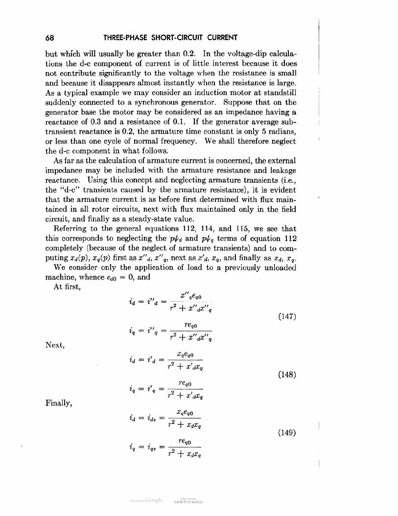
68 THREE-PHASE SHORT-CIRCUIT CURRENTbut which will usually be greater than 0.2. In the voltage-dip calcula-tions the d-c component of current is of little interest because it doesnot contribute significantly to the voltage when the resistance is smalland because it disappears almost instantly when the resistance is large.As a typical example we may consider an induction motor at standstillsuddenly connected to a synchronous generator. Suppose that on thegenerator base the motor may be considered as an impedance having areactance of 0.3 and a resistance of 0.1. If the generator average sub-transient reactance is 0.2, the armature time constant is only 5 radians,or less than one cycle of normal frequency. We shall therefore neglectthe d-c component in what follows.As far as the calculation of armature current is concerned, the externalimpedance may be included with the armature resistance and leakagereactance. Using this concept and neglecting armature transients (i.e.,the "d-c" transients caused by the armature resistance), it is evidentthat the armature current is as before first determined with flux main-tained in all rotor circuits, next with flux maintained only in the fieldcircuit, and finally as a steady-state value.Referring to the general equations 112, 114, and 115, we see thatthis corresponds to neglecting the ptd and p\l/q terms of equation 112completely (because of the neglect of armature transients) and to com-puting Xd(p), xq(p) first as x"d, x"q, next as x'd, xq, and finally as Xd, xq.We consider only the application of load to a previously unloadedmachine, whence ed0 = 0, andAt first,x"dx"qI I(147)req0Next,ld = l d =Finally,""- r2 + x"dx"q,x'dxq(148)+ XdXq(149)xdxq
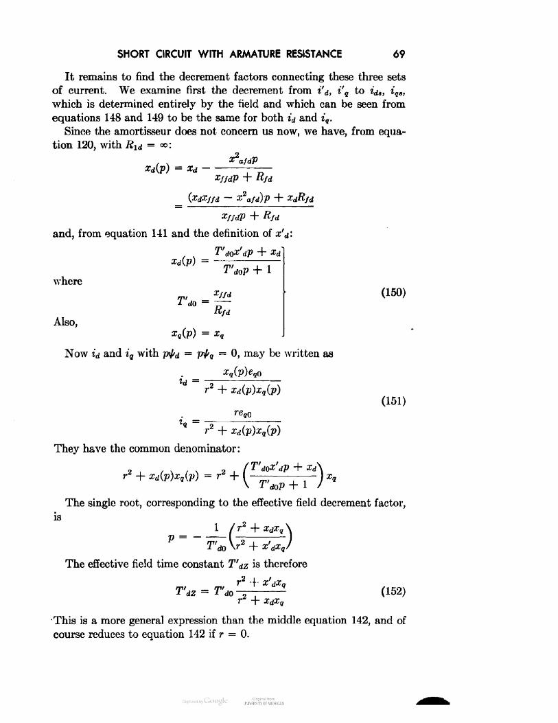
SHORT CIRCUIT WITH ARMATURE RESISTANCE69It remains to find the decrement factors connecting these three setsof current. We examine first the decrement from i'd, i'q to id,, iq,,which is determined entirely by the field and which can be seen fromequations 148 and 149 to be the same for both id and iq.Since the amortisseur does not concern us now, we have, from equa-tion 120, with Rid = °°:xd(p) = xd —X2afdP— X2afd)p ++ Rf<and, from equation 141 and the definition of ,Xd(p) =where+ 1m,1 d0 = —(150)Also,xq(p) = xqNow id and iq with ptd = Ptq = 0, may be written asid =r2 + xd(p)xq(p)(151)_r + xd(p)xq(p)They have the common denominator:xd(p)xq(p) =r= .2/T'd0x'dp + X\ T'd0p + 1The single root, corresponding to the effective field decrement factor,isP = -T'd0 \r2The effective field time constant T'dz is therefore= 1 dOr2 + xdxq(152)•This is a more general expression than the middle equation 142, and ofcourse reduces to equation 142 if r = 0.

70THREE-PHASE SHORT-CIRCUIT CURRENTIn the previous case of small armature resistance it was shown thatthe field short-circuit time constant could be regarded as the ratio ofthe short-circuit inductance viewed from the field winding to the field-winding resistance. Now it may be shown that the field time constantwith an armature load may be regarded in a more general way as theratio of an effective "load" inductance viewed from the field to the fieldresistance. This effective load inductance of the field may be calculatedas the ratio of field flux linkage to field current with the load connected.From the second equation 37 the field flux linkage is— XafdidBut, from equations 149 and 48,whenceorr + xdxqXdXg) — X2afdXq~xdxqIf*x'dxqxdxq(153)Still a third way of obtaining the effective field inductance is fromthe vector diagram as shown in Fig. 11. From this diagram and from
FIG. 11. Vector diagram with resistance load

SHORT CIRCUIT WITH ARMATURE RESISTANCE 71the previous discussion of Fig. 7, the ratio of the actual field flux linkageto the field flux linkage that would exist on open circuit istfd tfd iqr + idx'd(154)tfd0 gr + dxdBut it is also evident thatrid = xqiq (155)orid XQ- = ~t T(156)Substituting equation 156 in equation 154 leads to the same ratio as isgiven in equations 152 and 153.If subtransient components of current are neglected, the armaturecurrents areid = (i'd - ids)e-t/T'dz + id,iq = (»', - *,.)«-"*"" + V*o = [(i'd - ids) cos (t + 60) - (i'q - v) sin (t + &0)]rt/T'd,+ ids cos (t + 60) — iqs sin (t + 00)or finally, on substituting from equations 148 and 149,~eq0xdxq/ r + xdxqcos ( t + 00 + tan"1 — ] (157)\ xq/We observe that there is no change of phase between the transient andsteady-state components of current and that id and iq have the samedecrement factor.To find the decrement factors of the subtransient component, we haveto turn again to equation 151, let the field resistance be zero, and findtwo roots of the resulting quadratic equation obtained by considerationof the amortisseur resistance. Since there are two decrements, inex-tricably tied together, there remains the problem of assigning a propermagnitude to each component. This requires an actual operational solu-tion and cannot therefore be regarded as a simple approximation. Ifwe must resort to such a complicated procedure, we might as well solveequations 115 completely in the first place and not bother to constructthese approximate solutions. Instead, we simply use an average valueof the direct- and quadrature-axis amortisseur time constants (approach-
72 THREE-PHASE SHORT-CIRCUIT CURRENTing the open-circuit or short-circuit values depending on the magnitudeof the resistance) to determine the rate of decay of the subtransientcomponent. This apparently high-handed procedure is justified by theshort time involved, by the fact that subtransient effects may be neg-lected entirely in some calculations, and finally by the fact that forordinary machines the use of a single time constant for the amortisseuris only a crude approximation to the many time constants that actuallyexist so that we should be inconsistent in applying an "exact" methodto an approximate concept. Exact time constants for particular caseshave been computed in reference 11.Field CurrentThe change of field current has already been expressed in terms ofthe armature short-circuit current in equation 116. Moreover, com-parison of equations 116 and 119 shows us that for the condition of nochange in excitation voltage (which has been assumed for all cases studiedso far)ltd = pG(p)id (158) fIt should be evident that, since all currents arise from the same set ofsystem equations, the same decrement factors must apply to both fieldand armature currents, d-c components in the field corresponding to a-ccomponents in the armature, and conversely. Thus, if only an ap-proximate expression for the d-c components of field current is desired,it is only necessary to evaluate pG(p) first for p = w, next for p = °obut neglecting entirely the amortisseur, and finally for p = 0 [whencepG(p) = 0]. This procedure exactly parallels the calculation of x"d,x'd, and Xd required to obtain the a-c components of armature current.For the case of no amortisseur,G(p) = zaf* (159)+ Rfdand so the initial change of field current isMfd = [PG(p)]p=a Aid = — Aid (160)It is of interest to note that, if field excitation is measured in terms ofas is done on the rated-speed vector diagram discussed in Chap-t Note that in this equation wo must use the definition of G(p) as given in equa-tions 36 and 119, not the alternate form discussed following equation 48.

FIELD CURRENT 73ter 3, the initial value of A//,; may be expressed in terms of quantitiesmeasurable from the armature circuit as2xafd A//d = —— Aid = (xd — x'd) A^ (161)Xffd •This expression applies regardless of the load angle before the fault andof the fault (or armature) resistance, both of these variables having al-ready entered into the determination of Ai^.The vector diagram of Fig. 11 may be used to compute the changein field current with no amortisseur. Since the calculation is based onthe assumption that the field flux linkage remains constant at its pre-vious value (presumably unity), it is only necessary to scale up thediagram so that the voltage E'q is unity (or the value prevailing beforethe fault) and then measure directly the new magnitude of E (or xafdlfd).This is the average value of field current, not considering the funda-mental-frequency component, since it is based on the a-c component ofarmature current, not considering its d-c component.For a short circuit from no load and unit voltage the transient arma-ture current is l/x'd; so the change in field current, measured in termsof equivalent open-circuit voltage, isXd ~ x'dA# = Xafd A//d =x'dThe total initial field current for this case is thereforeXdE = Xafdlfd = Xafd A//d + 1.0 = —X'dThis may be of the order of ten times normal for high-speed machineshaving low transient reactance, and we must remember that there isin addition an a-c component having a peak value of (xd — x'd)/x'd. Ifthe machine has an amortisseur, examination of the various values ofpG(p) discussed above or a physical consideration of the circuits involvedshows us that the initially induced field current is reduced and thentends to approach the transient value of equation 161. That is, ini-tially the induced rotor current is shared by the field and amortisseur,roughly in inverse proportion to their leakage reactances. With typicalvalues of machine reactance, the subtransient induced field current maybe reduced to only about one third of the total induced current. Then,if we had x.d = 1.2, x'd = 0.12, the initially induced additional d-c com-ponent of field current might be only about 4 times normal. (It isgreater than 3 because the initial armature current is greater with an

74 THREE-PHASE SHORT-CIRCUIT CURRENTamortisseur.) Since it would rapidly rise to 9 times normal, this wouldnot seem to be of much significance. However, the fundamental-fre-quency component is also reduced to 4 times normal, so the peak fieldcurrent is reduced from (1 + 9 + 9 = 19) to (1 + 9 + 4 = 14) by theamortisfeur.SummaryIn this chapter we have studied in considerable detail various ap-proximations to the three-phase short-circuit current. It may almostseem more trouble than it is worth to derive these approximate formulas.However, we shall find that in many cases only initial values are needed,in many other problems the times involved are so long that amortisseurtransient effects may be neglected, in still others several other circuitsof the power system to which the machine is connected must be con-sidered. In this last case we shall find indispensable the idea (whichshould by now be firmly in mind) of considering the decay of the variouscomponents of short-circuit current as caused by the decay of fluxesinitially trapped in the individual machine circuits, the time constantof each of which is determined only by its own resistance and by aninductance calculated as the ratio of the circuit flux linkage to the cir-cuit current required to produce that flux linkage in consideration ofthe presence of all other circuits. This concept is also required in thestudy of unbalanced faults, where it will be found that approximationsare even more in order. Finally, an important reason for developingthe approximate formulas is to provide a method for analyzing short-circuit test data and thus for determining the machine constants bytest. That is, we construct a relatively simple formula each term ofwhich not only corresponds to a measurable component of current butalso is very simply related to the machine constants. It would be prac-tically impossible to figure out the machine constants from test usingthe "exact" equations. From this point of view we might even regardthe formulas as empirical, whence the constants are properly definedonly by the method of test, and the accompanying theory seems onlyan elegant but unnecessary burden. However, reflection and experienceshow that the theory is essential, first to predetermine the constants inthe design of machines, and second for their proper interpretation. Thefirst point is obvious, the second may be illustrated by an example.Since the amortisseur really contributes many time constants, we mightmeasure only the first few cycles of short-circuit current, separate thelog-current-versus-time curve into two straight-line components andthink we had determined a field-time constant, unless we had a suffi-ciently good idea of the magnitudes involved to realize the time interval
PROBLEMS 75that must be considered to obtain a proper separation. On the otherhand we must also realize the limitations of the theory, particularly inregard to magnetic saturation.Problems1. A synchronous machine having the characteristics,x"d = 0.30 p ux"q = 0.40and operating initially at no load, normal speed, and unit terminal voltage, issuddenly synchronized with a bus also at unit voltage but at an angle 50 behindthe machine generated voltage. Neglecting all resistances and decrements, andassuming that 5o does not change during the time interval considered, calculatethe subtransient armature current for various values of 60 from 0° to 360°for the system (i.e., bus) reactances xe = 0, 0.10, 0.20 and 0.40 p u. Calculatethe armature currents both with and without the d-c component, as in somecases the armature circuit resistance may be sufficiently high to practicallyeliminate the d-c component.2. A three-phase, Y-connected, 60-cycle, 50,000-kva, 13,800-volt synchronousmachine has the characteristics:Self-inductance of one armature phase winding = 0.008 henryMaximum value of mutual inductance between field winding and any onearmature phase winding = 0.04 henrySelf-inductance of field winding = 0.24 henryMutual inductance between any two armature windings = 0.0035 henry(a) Calculate the per unit synchronous reactance Xd and transient reactancex'd for this machine.(6) Calculate the per unit transient armature current for sudden short circuitfrom normal voltage at no load.(c) Calculate the per unit steady-state armature short-circuit current for afield excitation corresponding to a load of 1500 amperes rms at a power fac-tor of 0.9 (overexcited).(d) Calculate the transient induced field current in amperes and in per unitof the no-load, normal-voltage field excitation for sudden short circuit fromnormal voltage at no load.
5 SINGLE-PHASESHORT-CIRCUIT CURRENTSingle-phase short circuits may be either line to line or line to neutral.The only essential difference between the two types is that the line-to-neutral short circuit involves also the zero-phase-sequence impedancesof the machine and of any impedance connected between neutral andground if the fault is line to ground. They are considered togetherhere. As in the previous chapter constant rotor speed is assumed.Line-to-Line Short CircuitFor a line-to-line short circuit on phases b and c we have the conditions:eb — ec = 0(162)H + «c = 0and for no load:*o = 0Further, if armature resistance is neglected the total flux linkages ofphases b and c are maintained constant at their initial values 10 as deter-mined by ^M and iAc0, so thattb-tc = tb0 - ^c0 (163)If the machine angle at which the short circuit occurs is 60, thenv/'60 = ^d0 cos (60 - 120) - tg0 sin (6Q - 120)tc0 = td0 cos (00 + 120) - tq0 sin (00 + 120)ortb0 - tc0 = VSGfco sin 60 + ^90 cos 00) (164)Since a similar equation may be written for ^ — \l/c, equation 163 maybe reduced toiAd sin 6 + \l/g cos 6 = fa0 sin 60 + \l/qQ cos 6076
LINE-TO-LINE SHORT CIRCUIT 77Similarly, in terms of direct- and quadrature-axis quantities equations162 reduce toed sin 6 + eq cos 6 = 0id cos 6 — iq sin 6 = 0 (165)*0 = 0The form of these relations suggests that it may be advisable to setup the single-phase short-circuit problem in terms of new variables toreplace the direct- and quadrature-axis variables which seemed so ad-mirably suited to the study of balanced operation of a salient-polemachine. That is, if we define new variables asta — td cos 6 — \l/q sin 6tp = td sin 6 + t„ cos 6ea = <?d cos 6 — ea sin 6(166)ep = ed sin 6 + eg cos 6ia = id cos 6 — iq sin 6ip = id sin 6 + iq cos 6the conditions of our problem become simplyCH = 0(167)ia = 0i0 = 0The a, /3 quantities of equations 166 are seen to be referred to thestator or armature of the synchronous machine and may be regardedas equivalent two-phase currents which will produce the same air-gapfluxes as the actual three-phase currents. Figure 5 shows that ta isthe component of flux linkage in the direction of phase a and ^ is thecomponent in the direction of the common axis of phases b and c. Therelations 167 are also seen to be those for short-circuit of the j8 phaseof a two-phase machine, with a the open phase. The a-, fl-axis quantitieshave been defined in terms of the d-, g-axis quantities, but they maymore directly be defined in terms of the original phase quantities asshown below.Either by substituting equations 20, 23, and 28 in equations 166, ordirectly from Fig. 5, it may easily be shown that \l/a, ^p are similar to
78 SINGLE-PHASE SHORT-CIRCUIT CURRENTtd, tq but with 9 = 0. Therefore,ta = fW'a + tb COS (-120°) + tc COS 120°]to = ~ fW'6 sin (-120°) + +c sin 120°] (168)*a = !(*.- 3*6 - if.)ifo, = 1/V3 (*6 - *e) (109)Solving for the phase quantities from equation 169, by equations 34with 6 = 0, or simply by inspection of Fig. 5, we find1 .s/3-^ + -^-^ + ^0 (170)A —+with similar expressions for voltage and current.It has been remarked in Chapter 2 that equivalent two-phase quan-tities will be found much simpler to use than the original three-phasejquantities even for symmetric-rotor machines, such as induction motors.16In this case, and with balanced stator operation, either the d-, q-, 0-axisquantities or the a-, /?-, 0-axis quantities are equally well suited. Ifeither the rotor or stator is not symmetrical about every axis then thevariables should be referred to the unsymmetrical winding in order toobtain differential equations with constant coefficients. If both statorand rotor are unsymmetrical, as in the case of single-phase faults on asalient-pole machine that we are now considering, the equations willhave periodically varying coefficients regardless of the reference frameused, and an exact solution becomes rather complicated.It has appeared (equation 167) that at least the boundary conditionsare very simply expressible in terms of the a, ft, 0 quantities. Wetherefore proceed to investigate the flux-current relations. From equa-tions 36, since there is no change in field excitation G(p) = G(0)= Xafd/rfd. Then with (xafd/rfd)efd = E, we haveil'd = E - xd(p)idtq = -xq(p)iq (171)andt0 = —
LINE-TO-LINE SHORT CIRCUIT 79By equations 166,ta = cos 0 [E — xd(p)id] — sin 0 [— xq(p)iq]fp = sin 0 [E - xd(p)id] + cos 0 [-xq(p)iq]or, substituting ia, ia for id, iq by means of the relations,id = ia cos 0 + iff sin 0iq = — i„ sin 0 + ip cos 0we obtain\pa = —[cos 6xd(p) cos 0 + sin 0 xq(p) sin 0]4— [cos 6 Xd(p) sin 0 — sin 6 xq(p) cos 0]t/ 3 + E cos 0^,3 = —[sin 0 Xd(p) cos 0 — cos 0 x,(p) sin 6]ia (172)— [sin 0 Xd(p) sin 0 + cos 0 x«(p) cos 0]^ + E sin 0The a, /3 components of armature flux linkage are seen to be rathercomplicated functions of the a, /3 components of current for a salient-pole machine (only slightly less complicated than the a, b, c components).Note that the trigonometric functions cannot be simply combined be-cause the derivative operator p acts on the products ia cos 0, etc., andwe have not yet specified the exact form of Xd(p) and xq(p). Equations172 could be manipulated by converting the trigonometric functions tocomplex exponential functions and applying the operational shiftingformulas, but the result would be simple only for a symmetric-rotormachine. Moreover, if this conversion is made, we should also find itadvantageous to convert from the a, 0 quantities to symmetrical com-ponents at the same time.We do not, however, give up hope of applying the a, 0 components.Instead, we proceed to show how an approximate solution may be ob-tained by following a line of reasoning similar to that undertaken inChapter 4 for the three-phase short circuit.First, if we neglect all rotor resistances, Xd(p) = x"d and xq(p) = x"q,and the flux-current relations 172 become*« = -\{x"d + x"q + (x"d - x"q) cos 26]ia- \(x"d - x"q) sin 20 in + E cos 0(173)h = ~W'd -x"q) sin 20 4- \\x"d + x"q - (x"d - x"q) cos 20]t> + E sin 0In terms of a, /3, 0 quantities the voltage equations must be the sameas in terms of a, b, c quantities since the relations between the a, b, c,

80 SINGLE-PHASE SHORT-CIRCUIT CURRENTand a, /3, 0 quantities are linear with constant coefficients. From thephysical standpoint we say that the a, 0, 0 axes are fixed in the armaturejust like the a, b, c axes, so there are no generated voltages. Thus:— rip (174)e0 = Pt0 - riajust as in equations 1.If armature resistances are neglected we have ^ = i/^0, and, sinceia = 0, equations 173 becomeFor the armature current:sn 6 -x"d + x"q-(x"d-x"q)cos26and for the open-phase flux linkage:<;"x"d + x"q - (x"d - x"q) cos 26The open-phase voltage ea is given byh E cos 6 (176)atFor short circuit from no load \l/q0 = 0 in equations 166, and^00 = td0 sin 00 = e,0 sin 00 = E sin 00so that the currents ib and ic (see equations 170 and 175) become\/3E(sin 6 - sin 00)(177)x"d + x"q - (x"d - x"q) cos 26(178)where 6 = 6Q + t, 60 being the angle of the pole axis ahead of the axisof phase a at the instant of short circuit. It is evident that the currentmay be resolved into a series of odd time harmonics arising from thesin 6 term in the numerator and a series of even time harmonics arisingfrom the constant sin 60 term (the initial trapped flux linkages) in thenumerator. When 60 = 0 the initial flux linkages in the short-circuitedphases b and c (or /3 in the equivalent two-phase machine) are zero,and only odd harmonics appear. When 60 = ±90°, the pole axis isinitially lined up along the common axis of phases b and c, initial fluxlinkages are a maximum, and the corresponding .even-harmonic seriesis a maximum. The open-circuit voltage appearing across any of the

LINE-TO-NEUTRAL SHORT CIRCUIT 81machine terminals is 90° ahead of the flux linkages, so the even-harmonicseries is a maximum when the initial voltage across terminals b and cis zero.Phase QuantitiesAll the phase quantities for a line-to-line short 'circuit may be foundfrom equations 170 as:Since ia = t'o = 0,ia = 0V3.tb = — taV3.ic = HSince ea = e0 = 0,2Since ^a = i^o, ^o= 0,eO = ea = ppaeb = — \ea*«= *«fb1 .s/3= - - f<* + — taot,1 \/3= ~2^~^^°(179)(180)(181)We shall investigate the actual magnitudes and decrements of the short-circuit current and open-phase voltage components in a succeeding sec-tion, but first we shall show the very similar results for a line-to-neutralshort circuit.Line-to-Neutral Short CircuitFor a line-to-neutral short circuit the boundary conditions areea = 0. . (182)ib = ic = 0and for zero armature resistance:+a = +a0 (183)

82 SINGLE-PHASE SHORT-CIRCUIT CURRENTIn terms of the a, ,3, 0 quantities already developed, we may write,for short circuit from no load,f a + 4/0 = +a0 = ^aO = ^dO COS 60 = E cOS 0O (184)and'a = 3'aH = 0 (185)From the first equation 173 and the last equation 171 (i0 = — x0if\), wenow have*« + *o. = -hWd + x"q + (x"d - x"q) cos 2B]ia + Ecos6 -x0io= E cos 0Oor, using the current relations 185,3£"(cos 0 — cos 0O)la = '(186)x"« + x"q + (x"d - x"q) cos 20 + Xo K JFrom the second equation 173 and from equation 185, the 5 componentof flux linkage is+P = ~Wd - x"q) sin 20 ia + E sin 0or- (x"d - x",)£(c&s 0 - cos 0O) sin 26^=x"d + x"q + (x"d-x"q)cos2e + xfi + Esine (18?)Similarly, the 0 and a components of flux linkage areXo —x0E(cos 6 — cos 0O)^o = _ xo'o = ?a = (188a)3 x"d + x"q + (x"d - x"q) cos 20 + x0 V'and+a = -Wi + x"q + (x"d - x"q) cos 26]ia + Ecos6x"d + x"q + (x"d - x"q) cos 26E(cos 0 — cos 0O)+.E cos 6x"d + x"q + Xo+ (x"d - x",) cos 20[x"d + x"q + (x"d - x"q) cos 20]£ cos 0O + x0E cos 0x"d + x"q + xo + (j"d - x"q) cos 20(188b)

LINE-TO-NEUTRAL SHORT CIRCUIT 83The open-phase voltages may be found from the relations:e0 - ^° (189)1 \/3 3 V3eb = — - ea H — — e0 + e0 = — e0 H -- e022 221 \/3 3 \/3ec = -~ea - •— ep + e0 = ~e0 - — epIt may be seen that except for the addition of the zero-phase-sequencecomponents the line-to-neutral case is very similar to the line-to-linecase. The magnitude of the current for the line-to-neutral short cir-cuit is V3 = 1.73 times that (equation 178) for a line-to-line shortcircuit if x0 = 0. If, on the other hand, x0 = x"d = x"q = x", the line-to-neutral current is proportional to E/x" while the line-to-line currentis proportional to v3E/2x". Then the (l-ri)/(l-l) current ratio is2/ Vis 1.15.The line-to-neutral fault equations may be made to look evenmore nearly like the line-to-line equations if we define a new pair ofreactances, (x", i + x0/2) and (x"q + x0/2) for the line-to-neutral case.In fact, the first analysis " of single-phase short circuits from verynearly the present point of view used reactances of %(x"d + £0/2) and%(x"q + x0/2) for the line-to-neutral case, and of 2x"d and 2x"q forthe line-to-line case. These reactances of reference 17 are what wouldbe directly measured as the ratio of voltage to current in a test in whichsingle-phase line-to-line or line-to-neutral voltage of rated frequency isimpressed on the machine at standstill and under the present assump-tions. That is, either the direct- or quadrature-axis value (or any valuein between) could be found by lining up either the rotor pole axis orinterpole axis with the impressed magnetic field. Moreover, the sinus-oidal variation of the reactance can be directly tested by taking readingsat several known rotor angles. The analysis of reference 17 useda, b, c quantities and appropriate reactances for each case. The use ofthe a, ft, 0 quantities makes very little difference in the complexity ofthe analysis but does bring out directly the relations among the effectivereactances for the various types of fault.Our equations also indicate a difference in phase angle. That is, ifin equation 186 (with x0 = 0) we replace (6) by (6 — 90°), we obtainequation 178. The reason is of course only that we have chosen phase aas the reference phase in both cases. If we always took the magnetic

84 SINGLE-PHASE SHORT-CIRCUIT CURRENTaxis of the short-circuited phase or phases as the reference, this differ-ence would disappear.For the case of x"d = x"q the current magnitudes may be comparedto those for a three-phase fault. We then have the relative values:xo = 0 xa = x"d3,t> 100% 100%l-l 86.6% 86.6%Z-n 150% 100%Since the usual inherent zero-phase-sequence reactance of synchronousmachines is considerably less than the subtransient reactance, it is con-sidered good practice to ground the neutral points of any so-calledsolidly grounded central-station generators through a reactance largeenough to make XQ — x"d, so that the phase current, and thus thewinding forces, for a terminal-to-ground short circuit will not exceedthe three-phase value. If the neutral were directly grounded and if,for example, x0 = OAx"d (and x"d = x"q) the winding forces for a line-to-ground fault might be (3/2.4)2 = 1.56 times as great as for a three-phase fault.Open-Phase Voltage for Line-to-Line FaultEquations 176 and 177 show that it is only the subtransient saliency(i.e., x"d 7^ x"g) that leads to any change in the terminal voltage ofthe unfaulted phase. It is further evident that we can divide bothnumerator and denominator of the first term of equation 176 throughby x"d and thus show thatE(R — l)(sin 6 — sin 00) sin 20&* = — + E cos 6 (190)R + 1 + (R - 1) cos 20where-2,or that the change in open-phase flux linkage is a function only of theratio x"q/x"d. The open-phase voltage isea = pta = E(R - 1) {[R + 1 + (R - 1) cos 20]X [(sin 0 - sin 00)2 cos 20 + sin 20 cos 0]+ 2(R - l)(sin 0 - sin 00) sin2 20}•4- [R + 1 + (R - 1) cos 20]2 - E sin 0 (191)

HARMONIC COMPONENTS OF VOLTAGE AND CURRENT 85We may reasonably expect that maximum voltage will occur for shortcircuit with maximum trapped flux linkages (00 = ±7r/2), since thesetrapped flux linkages produce additional even-harmonic terms. Forthis case trial of various values of time (or of 6) will show that maximumvoltage occurs for 6 = 270°, etc., and thatea (nuo = ea (max) = E(2R - 1) = E ( 2 -^ - 1) (192)\ X d /If the machine under consideration is not grounded, but the faultinvolves ground, the voltages to ground, (ea — e6) or (ea — ec), will be,according to equations 180, 1J^ times as great as that given by equa-tion 192.In the usual modern machine having an amortisseur the open-phasevoltage is not very great. We have, for example:x"q/x"d ea (max) (eq. 192)1.0 1.01.2 1.41.4 1.8For a machine without an amortisseur these values may be much greater.The /3 component of the open-phase voltage for the line-to-neutralshort-circuit case is similar in form to the a or phase-a voltage for theline-to-line case. In addition there is a zero-phase-sequence component(see equation 189) which contributes to the total phase-6 and c voltages.Harmonic Components of Voltage and CurrentFor the line-to-line case the fault current of equation 178 may beresolved into the harmonic series (see Appendix A):. , [sin 0 - b sin 30 + b2 sin 50 - b3 sin 70 H 1x "d + Vx"dx"q\/3E sin 00- . „ [0.5 - b cos 20 + b2 cos 40 - b3 cos 60 H ] (193)whereVx"g - Vx"db = -7== 7= (194)Vx", + Vx"d

86 SINGLE-PHASE SHORT-CIRCUIT CURRENTSimilarly, for the line-to-neutral case we find3E„ , -vi . ii ,, x0X d \~[cos 6 + b0 cos 36 + 620 cos 56 + 630 cos 76 -\ ]ZE cos 60[0.5 + b0 cos 26 + 620 cos 46 + • • •] (195)where nowVx"q + 0.5x0 - Vx"d + 0.5x0b0 = — — - - (196)Vx"q + 0.5x0 + Vz"d + 0.5x0The relative magnitudes of the higher harmonic terms are somewhatsmaller for the line-to-neutral case than for the line-to-line case. If wetake as an example x"d = 0.25, x"q = 0.36, x0 = 0.14, then6 = 0.091, while b0 = 0.074 = 0.816If the machine has no amortisseur, we might have x"d = x'd = 0.36,x"q = xq = 0.64, x0 = 0.14. Thenb = 0.143, while b0 = 0.125 = 0.886The harmonic components of the open-phase voltage, for the line-to-line case, may be conveniently found by working from the current har-monics, instead of by a direct analysis of equation 191.From equation 173 the open-phase flux linkage is&» = - \(x"d - x"q) sin 2% + E cos 6or, from equation 193,1 | 2Eta= -~ (x"d ~ x"g) sin 26 - , „ [sin 6 - b sin 30".""2E sin 00 I+ b2 sin 50 ---- ] - . [0.5 - b cos 26 -j ---- ] + E cos 6 (197)Vx"dx"q IThis may be reduced by well-known trigonometric relations to_ E(x d - x^ _ _ _2(x"d+Vx"dx"q)^Esm60(x"d-x"q)(l-b2)+6(1 -62) cos 50 -..'] + - '- XZi V **/ d.C q(sin 20-6 sin 40 + 62 sin 60 ---- ) + E cos 0 (198)

HARMONIC COMPONENTS OF VOLTAGE AND CURRENT 87By differentiation a,nd combination of terms, we have the open-phasevoltage:ea = ea = pta = -E(1 + 6) (sin 6 - 36 sin 36 + 5b2 sin 56 ---- )- 4bE sin 00 (cos 26 - 2b cos 46 + 662 cos 66 ---- ) (199)The fundamental-frequency voltage in the open phase is thus increasedin the ratio:
6 = — T= - == = - (200)""The harmonic form of these voltage and current equations brings outthe relation between the results of the present analysis and the resultsof the application of the method of symmetrical components. If wedefine the quantity vx",ix"g as the negative-phase-sequence reactanceX2 and recall from our analysis of the three-phase fault that x"d thereplays the role of the positive-phase-sequence reactance xi, the funda-mental-frequency component of the line-to-line current (see equation193) becomesib = -ic = —•— (201)and the fundamental-frequency component of the open-phase voltage(see equations 199 and 200) becomes2x2ea = E (202)Xi + X2These familiar equations 201 and 202 show that the method of sym-metrical components gives the fundamental-frequency components ofvoltage and current correctly even for a salient-pole machine if for theline-to-line case x2 is defined as the geometric mean of the direct- andquadrature-axis reactances x"d and x"q. The factor b is also expressiblein terms of symmetrical-component reactances, by multiplying bothnumerator and denominator of equation 194 over by V x"d, asX2 — £1b = (203)x2 + xiFor the line-to-neutral case the relations are not so clear-cut and adifferent definition of x2 is required. It is evident from equation 195that the desired equivalence isxl ~f" X2 ~H XQ = X"d H

88 SINGLE-PHASE SHORT-CIRCUIT CURRENTor*•' + ?)(*-- + 7) -TWith this definition of x2, b0 is given byx2 — xiXi + X0(205)From equations 193 and 195 it is further evident that the d-c com-oonent of current is determined by the reactances:For the line-to-line case: 2x2,For the line-to-neutral case: 2x2 + XQReferring back to the three-phase case, under the assumption thatthe d-c component is determined by a reactance x2, we find, fromequation 128:For the three-phase case,^- = ^(^r + ^r) (206)orOT// ~.nx2 ~ -jj-','—"— (207)We may go a step further and imagine a short circuit through anexternal reactance xe, the same in all three phases. Then in all of thethree formulas, equations 208, 204, and 207, where equation 208 is(208)x"d and x"q are replaced by x"d + xe and x"q + xe, respectively, andthen xe must be subtracted to obtain the effective value of x2.If the external reactance becomes very large, we have approximately,for the line-to-line case:X2Xe = V(x"d + Xc)(x"q + Xe) 9* VX2e + Xe(x"d + X"q)x"d-*.V1+-whence(209)

HARMONIC COMPONENTS OF VOLTAGE AND CURRENT 89Similarly, for the three-phase case:2(x"d + *.)(x", + *.) x2e + xe(x"d + x"q)Xe =x"d + x"q + 2xe x"d + x"qXe H rr". _1_ 3."* d ~ •" 9The line-to-neutral case may also obviously be treated in the sameway, or for that matter by letting x0 be large even without any externalreactance.We have now four definitions of negative-phase-sequence reactance.These are compared in the following table (with x0 = Kx"d) for variousvalues of the ratio x"q/x"d-x"Jx"dEq. 208Eq. 204Eq. 207Eq. 2091.01.0001.0001.0001.0001.21.0951.0971.0901.1001.41.1831.1861.1671.2001.61.2651.2711.2301.3002.01.4141.4271.3331.500Except at rather large ratios of x"q/x"d, there is seen to be littledifference among the four formulas. Since many faults will be throughexternal reactance, it is convenient to have some idea of the effect ofintermediate values of xe. For example, if we take xe = 2x"d, the valuesof X2 calculated by the various formulas are as shown by the followingtable:x"q/x"dxilx"dxt/x"dxi/x"dxt/X"dEq. 208Eq. 204Eq. 207Eq. 2091.01.0001.0001.0001.0001.21.0981.0991.0971.1001.41 . 1941.1941.1871.2001.61.2861.2871.2731.3002.01.4641.4671.4291.500In view of these results, for most calculations requiring the use of x2it is sufficiently accurate to use the average of x"d and x"q as in equa-tion 209.
90 SINGLE-PHASE SHORT-CIRCUIT CURRENTDecrement FactorsThe values of current and voltage calculated above are those thatwould exist with flux linkage maintained in every closed winding of themachine. The average flux in all circuits will actually eventually decayto zero, except in the case of the direct-axis rotor windings. The odd-harmonic series corresponds to an even-harmonic series of rotor-currentcomponents; similarly the even-harmonic series corresponds to an odd-harmonic series of rotor-current components.The problem of determining the actual course of the current can beapproached in two ways. One is to make calculations including resist-ance for the symmetric-rotor case, which can be solved directly; theother is to estimate, as was done in the three-phase short-circuit case,a decrement factor for each circuit; this latter idea will be pursued first.The even-harmonic series of the armature will decay to zero approxi-mately exponentially with a time constant depending on the ratio ofthe effective armature inductance to the armature resistance. The effec-tive armature inductance for the d-c component in the line-to-linecase is the ratio of the line-to-line voltage V 3E to the current, orxa = 2vx"dx"q = 2x2. The armature resistance is 2r, so the armaturetime constant is- (210)For the line-to-neutral case, the effective resistance may include anyresistance rg of a grounding reactor. If the total zero-phase-sequenceresistance is r0, this grounding-reactor resistance will be (TQ — r)/3 = rg,or, conversely, the zero-phase-sequence resistance will be TQ = r + 3rg.The effective armature circuit resistance is r + rg and the effective re-actance is (see equation 195)d + 0.5x0) (z"9 + 0.5x0)since the circuit voltage is E in this case, so the time constant isd + 0.5x0)(x"9 + 0.5x0)a(l-n) = - ; -or"2V(x2r + r0 ~"2X2 + *° (213)2r + r0
DECREMENT FACTORS 91The odd-harmonic series will not decay to zero but will decay to asteady-state value corresponding to the original field current whichexisted before the fault. There will be induced in the field even in thesteady state a series of even current harmonics, but the average value(i.e., the d-c component) must be the same as the original current e/d/r/d.It should therefore be possible to compute the relative values of sub-transient, transient, and steady-state armature current by comparingthe average values of the initial rotor currents, the transient rotor cur-rent, and the steady-state rotor current.More specifically, we must calculate the rotor mmf 's (£o/,#/d + Xaidiid)and (£o19*19) rather than the currents, since it is the mmf that deter-mines the fundamental value of the armature current.At the first instant, flux is maintained in all rotor windings, and sowe may find from the second and third of equations 37 that the changeof field and amortisseur current in the direct axis is given byXffdifd + Xfidild = Xafdid(214)+ Xndlid = Xalor, solving for ifd and iid and combining, gives.Xafdlfd + Xaitfld = - : - o - T - ' - Id— X fid)= (Xd - x"d)id (215)This may be found directly from equations 116, 117, and 120 (or 123)by neglecting the resistances. In the quadrature axis, the second equa-tion 38, together with equation 124, gives for the change of rotor current:or2q = (xg - x" q)iq (216)It is now necessary to find the direct- and quadrature-axis currentsid and iq in terms of the currents ia and ip. The relations areid = ia cos 6 + is sin 6(217)^q = — la Sin 6 + Ift COS 6Since we are to be concerned only with the average (or direct) com-ponents of id and iq, it will be best to use the harmonic form of the cur-rent equations. From equation 193, the fundamental components ofcurrent (higher odd harmonics will not contribute to the average id

92 SINGLE-PHASE SHORT-CIRCUIT CURRENTor iq) in the line-to-line case are„ .. sing, ia(fund) = 0 (218)un „ .x d + V x dXwhence, by equations 217,(219)q (d-c) =From equation 215,-"(220)The steady-state value of (xafdifd + Xaidiid) before the fault isx^difd = E, so that the total average rotor mmf is all in the direct axisand is equal to(»„ - x"d)E^'d+V^d^q '" \x"dThus the rotor mmf is initially increased in the ratio,
/ Xd + Vx"dX"g \\x"d + Vx"dx"Jso the odd-harmonic components of armature current must eventuallydecay to a steady-state value obtained by decreasing the initial valuein the inverse ratio. Since the initial subtransient value equals thevoltage V3£ divided by (x"d + V x"dx"g), the final steady-state valuesimply equals the same voltage divided by xd + vx"dx"q. From thesymmetrical-component point of view the positive-phase-sequence react-ance has increased from x"d to Xd, but the negative-phase-sequencereactance has not changed. This seems reasonable since the negative-phase-sequence reactance corresponds to rapidly pulsating componentsof rotor current even in the steady state.In the steady state the average field flux linkage iswhere ifd and id are now the steady-state currents. Substituting inthe steady-state value of id, we findXafdEtfd = Xffdifd --' / „ „Xd + V X dX q

DECREMENT FACTORS93Clearing fractions and substituting E = xafjifd givesand sincetfd =X2afdxJfd= Xd — X'd(x'd + Vx"dx"q\ .r/d -1 - / „ „ ) Xffdifd\Xd + Vx'dX'q/(221)The final average field flux linkage is seen to be reduced from its initialvalue Xffdifd in the ratio:(222)It is therefore evident that in the transient state, after the averageamortisseur current has disappeared but before the field flux linkagehas been appreciably affected, both the field and the armature currentmust be greater than their steady-state values in the inverse ratio, so thetransient current equals the voltage V 3E divided by (x'd + W'd:c"9).The odd-harmonic components of the armature current thus behavevery much like the fundamental-frequency component of armature cur-rent in the three-phase short-circuit case, at least from the present some-what simplified point of view. As far as the positive-phase-sequence,fundamental-frequency components are concerned, it is more or less likea three-phase short circuit through an external reactance x2 = vx"dx"q,just as in the usual symmetrical-component treatment.The field time constant for the decay from transient to steady statemay be seen either from equation 221, which shows that the effectivefield inductance is reduced from the open-circuit value in the ratio 222,or from the concept of an equivalent three-phase fault through an ex-ternal reactance, to be(223)A simple extension of this reasoning shows that the decay from thesubtransient to the transient value is given by an amortisseur time con-stant,
(TV/* id (l-l)rri/t_ .dO'(224)dX'

94 SINGLE-PHASE SHORT-CIRCUIT CURRENTThe final expression for the current becomes••--•aV34(^-P7T^),-"'■'M+ ( , L_W„.+_L_|\rd + X2 Xd + X2f Xd + X2JX [sin 0 — b sin 30 + b2 sin 50 ]y/3E sin 0OJ"2wheree-'IT. (W) [0.5 - b cos 20 + 62 cos 40 ] (225)X2= Vi'V, (208)A similar analysis can be carried through for the line-to-neutral fault.Since the steps are so nearly the same, they will only be outlined. Thed-c component and all even harmonics have already been shown todecay to zero with a time constant given by equations 211-213.In connection with the odd-harmonic series, equations 214-217, de-fining the relations between the rotor and stator mmf and between id,iq, and ia, ip are of course independent of the type of short circuit.However the fundamental component of armature current is now (seeequations 195, 185, and 204):2Eia = cos 0, iff = 0 (226)X"d + X2 + XqwhenceEid (d-c) = ——; ; , iq (d-c) = 0 (227)x d + x2 + XoThe argument from here on is obviously identical with that for the line-to-line case, the final result being1ia = 3El\x"d + xd + x2 + x0 X'd + x2 + x0/+ ( 1 ) f-«T'i\L« +\x'd + X2 + X0 Xd + X2 + Xq/ Xd + X2 + XoX [cos 6 + b0 cos 36 + b20 cos 56 -\ ]3E cos 60- — [0.5 + b0 cos 26 + b20 cos 46 + • • ■ ] e~tlT° ((-> (228)x2 + 0.5x0
FIELD CURRENT 95wherez" X X1 d(l-n) - 1 dX d + X2 + XQ(229)J d (l-n) — 1 dOand x2 is given by equation 204.Field CurrentThe average component of the field current has already been discussedin connection with the determination of suitable decrement factors. Atthe first instant it is obtainable from equation 214, but more generallywe may use the relation 158 (see footnote to equation 158).A//d = pG(p)id (158)If resistances are neglected, this becomes (see equation 1 19 or 214)(230)XlldXffd — X fidNeglecting field resistance but also neglecting the amortisseur (i.e.,Rfd = 0 and Rid = °° in equation 119), we findXafd Xd — X d—id = - - - id (231)xffdNow it is evident from the physical nature of the problem that, ifwe calculate id (by equation 217) from ip (for the line-to-line fault) asgiven by equation 225 [ip = (2/ V S)ib], then for all harmonic terms ofid the corresponding harmonic term of //d may be calculated approxi-mately by equation 230. That is, the rotor current produced is sharedby the field and the amortisseur as determined by their reactances. Onthe other hand, the average term of the field current must be calculatedby equation 230 (and the average subtransient id) only at the firstinstant, and by equation 231 (and the average transient id) for thetransient component.

96 SINGLE-PHASE SHORT-CIRCUIT CURRENTTo illustrate the magnitudes involved, we may take as an examplethe following per unit machine parameters:xiu = l-l5xJ/d = l.20Xafd = Xa\d = XfU = l.00Xd = l.20x'd = 0.367x"d = 0.279x"q = 0.367x2 = WW', = 0.320Then equation 230 becomesA//d = xafd Alfd = 0.395i'd (232)and equation 231 becomesA/'/d = z*fd M'sd = 0.833t'<i (233)The average subtransient, transient, and steady-state values of id are,by equation 219 and the argument following it, and with the initialXafdIfd = E = 1.0,*'W> =-7r~l 1670X"d + x21i'd(d^ =- = 1.456X d + X?1id(d-e) — — 0.658xd + x2Thus the initial or subtransient change of average field current isM"sd = 0.395i"d = 0.660and the transient change in average field current isAI'fd = 0.833i'd = 1.213The total transient average field current isI'fd = M'f + 1.0 = 2.213This checks the ratio,VJ±=Xd±x1 = 1.520 ^^Ifd x'd + x2 0.687which was derived (equation 221) from a calculation of the steady-statefield flux linkage.

SUMMARY 97The average field current thus rises abruptly at first from 1.00 to1.66, then increases further with the subtransient time constant to 2.21,and finally decreases with the transient time constant to 1.00 again.All the harmonic components of field current may be computed in thesame way. We shall not derive an explicit formula for field current,since the harmonic form of id may be computed by equation 217 verysimply for any particular case. Similar considerations apply to the cal-culation of field current for the line-to-ground fault.SummaryIn this chapter we have computed the short-circuit current of a salient-pole synchronous machine for the two similar cases of line-to-line andline-to-ground faults through small external resistance.For these cases it has been found convenient to introduce substitutevariables ia, ip, i0 to replace the phase quantities ia, ib, ic. The savingin labor is not very great, but the method has the virtue of enabling usto use the same machine constants previously defined for the three-phase case. The ia, ip, variables may be regarded as currents flowingin an equivalent two-phase machine. They will be found useful in otherproblems.The results obtained have been shown to parallel in every respect thoseobtainable by the method of symmetrical components and in additionto give values for the harmonic currents and voltages. The results alsoprovide definitions for the negative-phase-sequence reactance x2 validin each case, showing that, strictly speaking, x2 is not simply a constantfor salient-pole machines..The decrement factors have been shown to be obtainable from thepoint of view of an equivalent balanced fault through a proper externalreactance, since it is only the positive-phase-sequence component of thefundamental component of armature current that reacts on the averagecomponents of rotor flux.. In other words, it is only the positive-phase-sequence, fundamental-frequency current that produces an effectivearmature reaction, all other components producing fluxes that alternaterapidly in every rotor winding. Incidentally, we may with profit nowreturn to the three-phase short-circuit case of Chapter 4 (from no loadonly) and rederive the sustained and transient currents from the sub-transient value by the method of the present chapter, i.e., from con-sideration of the rotor average mmf's.The harmonic open-phase voltages produced are not in themselveslarge for the usual parameters of machines having amortisseurs. Theyare of interest, however, because cases of high voltage have arisen in

98 SINGLE-PHASE SHORT-CIRCUIT CURRENTconnection with machines not equipped with amortisseurs, when theopen phase has been connected to a transmission line. The transmission-line capacitance may increase the voltage considerably as it may besufficiently great to approach resonance with the third or fifth harmonic.18The even harmonics do not concern us so much here because they arenot sustained.Finally, we have outlined a method for computing the field current.Problems1. Calculate the induced field current for a line-to-ground fault for the ma-chine discussed in connection with equations 232 and 233 for various values ofzero-sequence reactance XD.2. Calculate the transient and sustained values of armature current for athree-phase fault from the viewpoint of this chapter, that is, by a considerationof the rotor mmf's (see equations 214-222).3. Calculate and plot the curves of the armature and field currents for aline-to-line fault on a synchronous machine having the characteristics:Xd = 1.25 p uxq = 0.75Xafd =1.10Xffd = 1.20No amortisseurand operating at no load and normal voltage. The short circuit occurs at theinstant when the flux linkages in the short-circuited coils are a maximum.Neglect all resistances.4. Calculate and plot the voltage on the open armature coil for the machineof problem 3.6. The machine of problem 3 has a field current of 350 amperes at no loadand normal voltage. Plot the field current in amperes for the line-to-line shortcircuit.6. Consider a symmetric-rotor machine having the characteristics:Xd = Xq = 1.25 p UXafd = Xafq =1.10Xffd = xffq = 1.20rid = rf<1 = 0.001r = 0.01For a line-to-line short circuit as in problem 3, calculate and plot the armatureand direct-axis field currents neglecting all resistances. Compare these cur-rents to those of problem 3 to show the effect of saliency.

PROBLEMS 997. Include the effect of the stator and rotor resistances in producing decre-ments, for the machine of problem 6.8. Consider the salient-pole synchronous machine having characteristics:Xd = 1.0 Xalq = 0.4Xffd =1.0 rid = 0.02xnd = 0.95 rlg = 0.04Xafd = Xaid = Xfid = 0.8 rf = 0.0004xq = 0.6 r = 0.005xu, = 0.7Calculate and plot the armature current for a line-to-line short circuit at bothminimum and maximum initial flux linkages.

O DOUBLE-LINE-TO-GROUNDSHORT CIRCUITAND SEQUENTIAL FAULTSIn addition to the three-phase, line-to-line, and line-to-ground shortcircuits considered previously, a synchronous machine may have twoterminals simultaneously short-circuited to ground or neutral or mayhave two or all of its terminals short-circuited in various sequences.We shall consider the double-line-to-neutral short circuit from no loadin this chapter and shall only very briefly discuss the consequences ofsequential faults and of initial load.The terminal conditions for a two-line-to-ground fault from no loadon phases b and c areeb = ec = 0(234)ia = 0and for zero armature resistance^b = iw, "Ac = ico (235)In terms of the a, 0, 0 quantities defined in Chapter 5 these terminalconditions becomeea = 2e0ep = 0to = —ia (236)to — 2^0 = taO — 2"Aoo = iad = E COS 60is = f 00 = E sin 0OThe initial or subtransient currents may be found directly from equa-tions 173 (with "Ao = —x0io = -\-x0ia) as100

DOUBLE-LINE-TO-GROUND SHORT CIRCUIT 101{[x"d + x"q + (x"d - x"q) cos 20] + 4x0}*« + (x"d - x"q) sin 2Bif= 2£'(cos 0 - cos 0O)(237)(x"d - x"q) sin 261 ia + [x"d + x"q - {x"d - x"q) cos 26]ip= 2E(sin 6 - sin 0O)whence the currents areia = —io = £"{(cos 0 — cos 60)[x"d + x"q — (x"d — x"q) cos 26]- (sin 6 - sin 60)(x"d - x"q) sin 26} h- D (238)i0 = E{(sin 6 - sin 60)[x"d + x"q + 4x0 + (x"d - x"q) cos 26]- (cos 5 - cos 9o)(x",j - x"q) sin 26) ^ D (239)where£> = 2[x0(x"d + x"q) + x"dx"q - x0(x"d - x"q) cos 26]orD = x"d(x"q + 2x0) + x"q(x"d + 2x0)- [x"d(x"q + 2x0) - x"q(x"d + 2x0)] cos 26 (240)These equations may be reduced toE[2x"q cos 6 - (x"d + x"q) cos 0O + (x"d - x"q) cos (20 - 60)]4 =(241)f #[(2x"« + 4x0) sin 6 - (x"d + x"q + ix0) sin 60]i + (x"d - x"q) sin (26 - 60)] I20 = {Z4:l)It is evident that these two currents may each be resolved into evenand odd Fourier series just as in the case of the single-phase faults.Moreover the second of the pair of equations 240 for the denominator Dhas been made similar in form to the denominator of equations 175 or178 so that we may recognize without further consideration (at leastfor the odd-harmonic series), the value of the geometric ratio b, whereVx"q(x"d + 2x0) - Vx"d(x"q + 2x0)~ Vx"q(x"d + 2x0) + Vx"d(x"q + 2x0)and we may calculate the magnitude of the various harmonics if thisbecomes necessary. It does not seem worth while to write down theharmonic expressions at length here as it is merely an algebraic exercise(these expressions are given in reference 19 and in Appendix A), but
102 DOUBLE-LINE-TO-GROUND SHORT CIRCUITwe shall look in some detail at the fundamental and d-c componentsin order to determine the decrement factors. The fundamental com-ponents are (see Appendix A)2E cos 6Mfund> = x"d + 2*0 + V(x"d + 2x0)(x"q + 2x0)x"d/x"q2E sin 6un x"d + Vx"dx"q(x"d + 2xQ)/(x"q + 2x0There seems little doubt that we are about to discover another defini-tion of negative-phase-sequence reactance x2. The most convenientrelation from the theory of symmetrical components is that the positive-phase-sequence current ii is given byh = - - - (245)X2 + X0The positive-phase-sequence component corresponds to the average(d-c) components of id and iq, since these currents are constant withrespect to the rotor and so are rotating in positive phase sequence andwith fundamental frequency with respect to the stator. We refer toequations 217 and computeE"x"d + 2x0 + V(x"d + 2x0)(x"q + 2x0)x"dWfqEx"d+Vx"dx"q(x"d + 2x0)/(x"q + 2x0) (246)*9 (d-c) = 0The coefficient of ei in equation 245 should equal the coefficient ofE in equation 246. The reason for this quantitative agreement is shownlater in this chapter in the section on symmetrical components.It does not seem possible to arrive at a simple formula for x2 fromthis equivalence, but we can calculate x2 for various values of theparameters and compare it to the values found by the previous formulas.From equation 245, solving for x2, we findx2 = —— (247)xi + x0 — Xwheree EX = - = (248)ii id (d-c)

SYMMETRICAL COMPONENTS 103Since we are interested only in relative values we shall assign all quan-tities in per unit of x"d and consider the five cases:x"d = xi = 1.0x' q = 1.4x0 = 0.01, 0.3, 1.0, 2.0, and ooFor these cases:X = 1.0099, 1.239, 1.54, 1.743, and 2.183andx2 = 1.167, 1.172, 1.173, 1.181, and 1.183All of these values of x2 are in line with our previous results. The lastvalue, for x0 = », of course checks the line-to-line case, x2 = V x"dx"q,while the first value, for x0 = 0, checks the three-phase case, x2= 2x"dx"q/(x"d + x"q). From the symmetrical-component relations,we should also have (page 87 of reference 20):i2 Xq io x2- = and - = (249)ti x2 + x0 ii x2 + x0where i2 = the negative-phase-sequence component of current, and thismay result in still different values of x2. In order to test this we mustfind i2, so we now proceed to determine the quantitative relations be-tween the two-phase components and the conventional symmetricalcomponents.Symmetrical ComponentsSymmetrical components for three-phase systems are usually definedfrom a physical viewpoint as three sets of quantities (e.g., currents):the first a balanced three-phase set of normal phase rotation (the posi-tive-phase-sequence current), the second a balanced three-phase set ofopposite phase rotation (the negative-phase-sequence current), the thirda set of three equal currents (the zero-phase-sequence current). It isshown that it is always possible to compose any set of three unbalanced,normal-frequency currents (or voltages) by a proper addition of thethree sets of symmetrical components. If we define these componentsas: for the positive-phase-sequence set, ia\, ib\, ici', for the negative-phase-sequence set, ia2, ib2, ic2', for the zero-phase-sequence set, iao,ibo, ico, then the three phase currents areia = ial + ia2 + la0ib = h\ + h2 + ibo (250)ic = ici + ic2 + ico
104 DOUBLE-LINE-TO-GROUND SHORT CIRCUITThe virtues of using symmetrical components are that in terms of thesecomponents the impedances of the usual three-phase systems either areknown or can be more or less easily computed, and that well-knownformulas are available to handle various cases of unbalanced operation,such as faults. In particular, if the rotor is assumed to be completelysymmetrical, impedances to positive-, negative-, and zero-phase-sequencecurrents may be easily determined for a synchronous machine. Positive-phase-sequence currents combine to produce only a flux wave rotatingpositively at synchronous speed. As far as the rotor is concerned, it isa constant flux and so produces no voltage drop. Thus the machinepositive-phase-sequence reactance is the synchronous reactance as de-scribed in Chapter 2. In effect, the conditions are those for the "sliptest" discussed there. Similarly, for a symmetric-rotor machine nega-tive-phase-sequence currents combine to produce only a flux wave rotat-ing negatively at synchronous speed. As far as the rotor is concerned,this is a double-frequency flux since it is rotating backward at twicenormal speed. With usual rotor resistances the rotor flux linkages pro-duced are very small, and so practically speaking the impedance metis the short-circuit, or subtransient, reactance. Finally, the zero-phase-sequence currents combine to produce no flux linking the rotor, so that,regardless of rotor conditions, the zero-phase-sequence impedance isencountered.If we are to compare the two-phase and symmetrical components wemust have a mathematical definition of symmetrical components. Adefinition in line with the foregoing physical concept, and one that isvery widely used, is+ aib + a2U+ a2i6 + aie) (251)where(a) ia, ib, ic are complex numbers defined so that ,ia = real part of iaib = real part of ib (252)ic — real part of icand so that they have as a factor e"**, where w is the angular frequencyof the quantities ia, ib, ic. For example, if ia — I cos (ut + a), thenia = / cos (ut + a) + jl sin (ut + a) = TV V"'

SYMMETRICAL COMPONENTS 105(b) a = e^/3•- - - j - (253)and finally the symmetrical components are(c) iai = real part of iiibi = real part of a iiid = real part of ai1ia2 ~ real Part of *2 (254)ib2 = real part of ai2ic2 = real part of a2i2ia0 = ib0 = ic0 = real Part of i0Note that this is not the only possible mathematical definition, butit is believed to be the simplest, especially in view of the fact that theuse of equivalent complex voltages and currents is practically universalamong electrical engineers.It is customary in many calculations to leave out the factor e*ut anduse merely its complex coefficients as the currents or voltages. It isimportant, however, in the present case to consider this factor becausewe want to compare our results with the instantaneous values foundby the two-phase component method. Also, in many cases the quan-tities ii, i2, i0 (or the coefficients of r"* in these quantities) are them-selves called the symmetrical components. We shall follow this practicein the subsequent development.Equations 251 may be put in the form:1 I" 1 . . \/3 . .111 ~ 3 L1" 2 16 lc J 2 lb lc \1 f 1 V3 I12 = - ia - - (it + ic) -j'— (it - Uo L 2i & \(255)or, in view of equations 169:12 =
106 DOUBLE-LINE-TO-GROUND SHORT CIRCUITwhere, since the relations between ia, ib, ic and ia, ip, i0 are all real,the quantities ia and 10 are such thatia = real part of ia(257)ip = real part of 10Also from equations 256:ia = ii + i2(258)It may superficially seem that we have gone a long way around here,since if without bothering to introduce completed equivalent complexphase currents we had defined quantities ii, i2, i0 by equations 251 interms of the real currents ia, ib, *« we should have arrived at exactlyequations 256 and 258 in terms of the real ia, ip, and of ii, i2. Weshould have been getting nowhere however since the quantities ii, i2(although in general complex) are not the conventional symmetricalcomponents and do not have their desirable properties of correspondingto positively or negatively rotating flux waves in electric machines. Forexample, if the real currents areia = I COS utib = I cos (ut - 120°) (259)ie = I cos (ut + 120°)which are known to produce only a positively rotating flux wave; thenia = /e*"ib = /«-^/V" = as/e*" (260)ie = /e+^/V6" = ale>atand, by equations 251,11 = /e;'*"12 = 0 (261)io = 0On the other hand, if the real currents are used directly in equations251 we find«0 = 0

SYMMETRICAL COMPONENTS 107so that there is no correlation between the direction of the physicalrotation and the correspondingly labeled current component.A further legitimate question is how to complete the phase currentsto form the complex quantities when they are not simply sinusoidal.In most cases, however, if the currents are not sinusoidal they will havearisen as the solution of some differential equation having originallyeither a sinusoidal or constant forcing function, so that they containsinusoidal factors which may be simply converted to exponentials. Inthe present case this question does not arise.Equations 256 have now shown us the way to go from the two-phasecurrents to the symmetrical-component currents. Referring to equa-tions 243 and 244 we see that, if we let(l) = X"dThenia = A2E cos 6(202)ip = B2E sin 6By equations 257,ia = A2EJO(263)ip = -jB2EejeBy equations 256,ii = (A + B)Eeje(264)ia = (A -Since E(j e = C1, it is evident that (A + B) is equivalent to 1/X, asstated after equations 246, which may be rewritten in the presentnotation as: id (d^ = (A + E)E.Similarly:i2 XQ A — B- = -- — = - (265)i! x2 + x0 A + BSince (I/A) and (1/JB) are simpler than A and B, we express x2 as(266a)— - —\A B)

108 DOUBLE-LINE-TO-GROUND SHORT CIRCUITor[x"d + Vx"dx"q(x"d + 2x0)/(x"q + 2x0)]2x0 , =.— (260 b)f -4- \/fv" 4- 9r \<T" .4- 9r W'j/Vt'O l * \^ d i ^S^O/V*** 7 I «*0^« ,j/•*•- VVV,)(z"d + 2zb)/(z", + 2x0)It can easily be shown that the value of x2 obtained from equa-tion 266 also lies between x2 = V x"dx"q for XQ = no and x2 = 2x"dx"q -=-(z"d + x"q) for x0 = 0, just like the x2 found from equation 247.Rotor Decrement FactorsSince we have shown in connection with the line-to-line fault that,from the standpoint of armature reaction on the rotor average fluxes,the machine behaves practically as if it were subjected to a balancedshort circuit through an appropriate external reactance, we may writedown at once the rotor subtransient time constant asT" -L Trrin rriff e /Of7\i d(ll-n) — i dQ——— (/Of,)X d I Xewhere, for the double-line-to-ground fault,X2XQxe = (268)X2 + XQand the field, or rotor transient, time constant asT' 4- Trt rrtf /Oco\d (ii-n) — i d0 (/oy;Xd + XeThe transient and steady-state components of armature current may befound as in the previous chapter from a consideration of the initial rotoraverage mmf and the final field flux linkage.From equation 215, and adding in the steady-state value of £a/dVej(or E), the total initial average rotor mmf is+ Xaldild = (xd — x"d)id (d-c) + E(xd - x"d)Ex"d + 2x0 + V(x"d + 2x0)(x"q + 2x0)x"d/x"qf x"d + Vx77^^", + 2x0)/(x"q + 2*0) +'''(270)

STATOR OR ARMATURE DECREMENT FACTORS 109This could be evaluated for any particular case, but it seems moreadvisable for a general formula to return to the symmetrical-componentpoint of view, whence it is evident thatXafdif + Xauild Xd + Xe- = (271)E x"d + xeSimilarly, the steady-state average field flux linkage may be computed asJO $ I ^gi/]d = ——— Xffdifd (272)%d ~\~ Xqjust as was done for the line-to-line case in equation 221. In both theseequations x2 lies between the limits,2x"dx"q r—- ~ <x2< Vx"dx"q (273)X d I X qThus the complete course of the odd harmonics has been determined.They may be written as2x"qEcos6 \(a x"d + xM , T„,J5/coser/ x"d + xe\x'd + x,X"d + Xe(X 'd + Xe X d + Xe\\ x'd + xe xd + xe /(274)xd + xewhereXoXnxe = —L2- (268)x2 + x0as before, and the time constants are given by equations 267 and 269.Similarly:2(x"q + 2x0)E sin 6*0(odd) =DI x"d + xe\\ X'd + xe /— t/T". (X d v Xe X d\ Xe\ ^,/rp,+ I — 1 e (/i " <«-») +\ X d + xe Xd + xe /%d i *e(275)Stator or Armature Decrement FactorsTo compute the armature time constants it is convenient to think ofthe two components of current ia (or — i0) and ip as flowing more orless independently in the armature circuits. It at once becomes evident
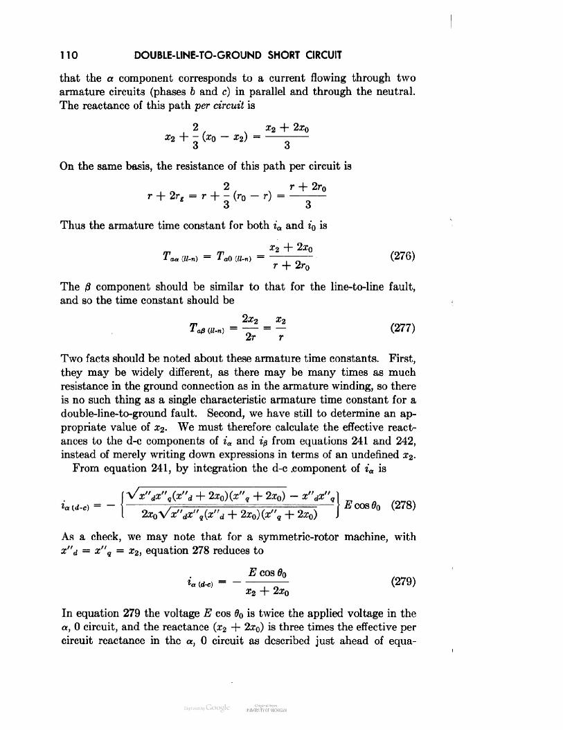
110 DOUBLE-LINE-TO-GROUND SHORT CIRCUITthat the a component corresponds to a current flowing through twoarmature circuits (phases b and c) in parallel and through the neutral.The reactance of this path per circuit is2 x2 + 2x0x2 + ~ O0 - *•) =O OOn the same basis, the resistance of this path per circuit is2 r + 2r0r + 2re = r + - (r0 - r) =O OThus the armature time constant for both ia and i0 isX2 + 2x0Taa (U-n) = TaQ («_„) = — (276)r + 2r0The ft component should be similar to that for the line-to-line fault,and so the time constant should be2x2 x2Tap (u-n) = —— = — (277)2r rTwo facts should be noted about these armature time constants. First,they may be widely different, as there may be many times as muchresistance in the ground connection as in the armature winding, so thereis no such thing as a single characteristic armature time constant for adouble-line-to-ground fault. Second, we have still to determine an ap-propriate value of x2. We must therefore calculate the effective react-ances to the d-c components of ia and ip from equations 241 and 242,instead of merely writing down expressions in terms of an undefined x2.From equation 241, by integration the d-c .component of ia is2x0)(x"q + 2x0) - x"dx"gla (d-c) = - - / - l ( E coS 00 (278)° 2x0Vx"dx"q(x"d + 2x0)(x"q + 2x0)As a check, we may note that for a symmetric-rotor machine, withx"d = x"q = x2, equation 278 reduces toE COS 0n(279)-x2 + 2x0In equation 279 the voltage E cos 00 is twice the applied voltage in thea, 0 circuit, and the reactance (x2 + 2x0) is three times the effective percircuit reactance in the a, 0 circuit as described just ahead of equa-

STATOR OR ARMATURE DECREMENT FACTORS 111tion 276. Thus ia should be two thirds as big as the component of ibor ic produced by ia and Z'Q. Reference to equations 170 and 236 showsthis to be true, as, from equation 170,ib(=! ic) [produced by ia and i0] — —\ia + i0but by equation 236 i0 = —ia, and soib(= ic)[produced by ia and i0] = — %iaThe formula for the proper x2 is now2x0Vx"dx"q(x"d + 2x0)(x"q + 2x0)x"dx"q(x"d + 2x0)(x"q + 2x0) - x"dx"qd 0g 0 - dgSimilarly, from equation 242 the d-c component of ip isVx"dx"q(x"d + 2x0)(*", + 2x0) - (x"d + 2x0)(x"q + 2x0)]E sm 002x0Vx"dx"q(x"d + 2x0)(x"q + 2x0)(281)For a symmetric-rotor machine, with x"d = x"q = x2, equation 281reduces toE sin 00ifl (d-c) = (282)£2The expression within the curved brackets of equation 281 is there-fore the reciprocal of the effective x2 for this case. The voltage E sin 00is I/V 3 times the applied voltage in the /3 circuit, and the reactance x2is half the effective circuit reactance. Thus ip should be 2/V 3 timesas big as the component of ib or ic produced by ip (see equations 170).Summarizing the results obtained so far, we have found that thephase currents ib and ic for a double-line-to-ground fault on phases band c are given approximately by the equations:E \ib = — -[3x"q cos 6 - \/3(z"9 + 2x0) sin 6]C+ %[(x"d + x"q) cos 00 - (x"d - x"q) cos (20 - 60)\AV3~- — [(x"d + x"q + 4x0) sin 00 - (x"d - x"q) sin (20 -£i(283)
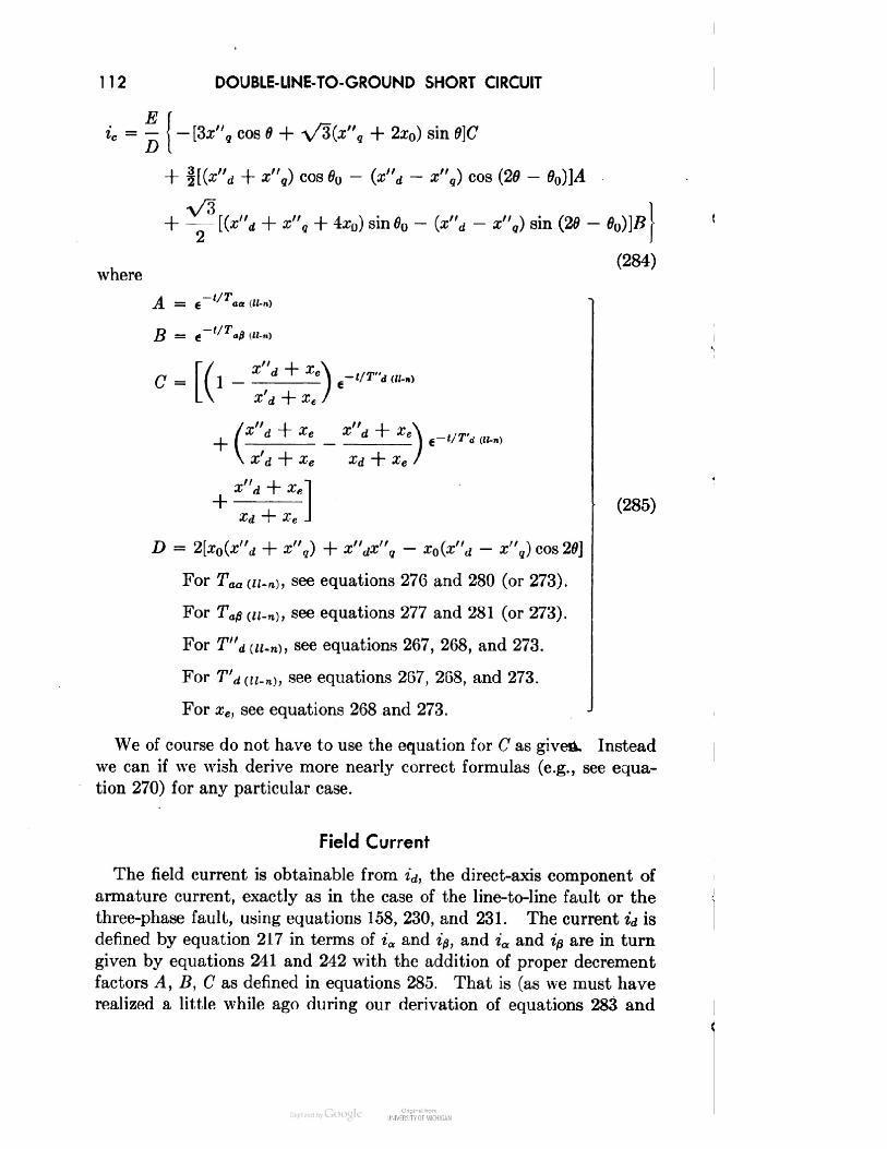
112DOUBLE-LINE-TO-GROUND SHORT CIRCUITET fic = - -[3x"q cos 0 + \/3V9 + 2x0) sin 0]C+ %[(x"d + x"g) cos 00 - (x"d - x"g) cos (20 - 00)]AV3i r/^" i «"wheresin 00 - (z"d - x"9) sin (20 - 00)]#J(284)B = « t/Ta0W-n)f X d -p £c Z d t ^e \\ z'd + xe a;d + xe /+ ^^1»C(i I «C« -I(i,.,)(285)D = 2[x0(x"d + x",) + z"«jx", - a;0(z"d - x",)cos20]For Taa(u.n), see equations 276 and 280 (or 273).For Ta0<«-n), see equations 277 and 281 (or 273).For T"d(H-B), see equations 267, 268, and 273.For T'd(n-n), see equations 267, 268, and 273.For xe, see equations 268 and 273.We of course do not have to use the equation for C as given. Insteadwe can if we wish derive more nearly correct formulas (e.g., see equa-tion 270) for any particular case.Field CurrentThe field current is obtainable from id, the direct-axis component ofarmature current, exactly as in the case of the line-to-line fault or thethree-phase fault, using equations 158, 230, and 231. The current id isdenned by equation 217 in terms of ia and ip, and ia and ip are in turngiven by equations 241 and 242 with the addition of proper decrementfactors A, B, C as defined in equations 285. That is (as we must haverealized a little while ago during our derivation of equations 283 and

OPEN-PHASE VOLTAGE113284 for ib and ic), A multiplies all the even-harmonic terms of ia, Bmultiplies all the even-harmonic terms of ip, and C multiplies all theodd-harmonic terms of both ia and ip.
FIG. 12. Double-line-to-ground fault. Effect of XQ on open-phase voltage. Com-parison with line-to-line faultOpen-Phase VoltageThe voltage ea across the open phase a is given bywhere(280)(287)

114 SEQUENTIAL FAULTSor, by equation 173,*o = -Wi + x"q ~ 2x0 + (x"d - x",) cos 26]ia- \(x"d - x"q) sin 20 i& + E cos 6 (288)The maximum open-phase voltage can be either greater or smallerthan that for a line-to-line fault, largely depending on the value of x0.Figure 12 shows a comparison of values calculated neglecting all decre-ments with similar line-to-line values.Sequential Application of FaultsThe principal effect of the sequential application of faults is on thed-c component of short-circuit current. We shall therefore considerfor simplicity only a symmetric-rotor case and shall moreover neglectall rotor resistances. This means that we shall neglect all decrementsof the a-c component of currentbut shall obtain approximatelythe right answers for the d-ccomponents.With these simplifying assump-tions the machine may be repre-sented by the equivalent circuitof Fig. 13, in which
3 1Sl^icx,*en=-ESINeeh=-ESIN<e•I20')ec=-ESIN(8 +I20')x\ — x d — x qX0 = 3xn + X!x2(289)Fia. 13. Simplified equivalent circuit forsynchronous machineThe propriety of this circuitmay be shown directly by apply-ing positive-, negative-, and zero-phase-sequence voltages in turn and observing that the currentsresulting are correct in all cases. It may also be shown by lettingx"d = x"q = Xi in equations 173, whence\l/a = — Xiia + E cos 6^ = -xiip + E sin 6 (290)^o = — x0ioand, by equations 170,"Ao = —xiia — (x0 — xi)i0 + E cos 6ih = -xiib - (x0 - xi)i0 + E cos (6 - 120) (291)^c = — xiic - (x0 — xi)io + E cos (0 + 120)Then, in view of equations 1, the circuit of Fig. 13 results.
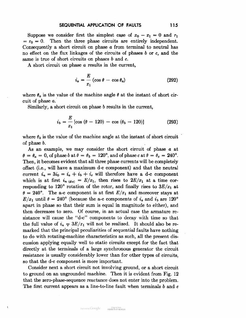
SEQUENTIAL APPLICATION OF FAULTS 115Suppose we consider first the simplest case of x0 — xi = 0 and Tl= r0 — 0. Then the three phase circuits are entirely independent.Consequently a short circuit on phase a from terminal to neutral hasno effect on the flux linkages of the circuits of phases 6 or c, and thesame is true of short circuits on phases b and c.A short circuit on phase a results in the current,Eia = — (cos 6 - cos 0a) (292)Ziwhere 6a is the value of the machine angle 6 at the instant of short cir-cuit of phase a.Similarly, a short circuit on phase b results in the current,Eib = — [cos (6 - 120) - cos (06 - 120)] (293)where 06 is the value of the machine angle at the instant of short circuitof phase b.As an example, we may consider the short circuit of phase a at6 = 6a = 0, of phase 6 at 6 = 6b = 120°, and of phase c at 6 = 0c = 240°.Then, it becomes evident that all three phase currents will be completelyoffset (i.e., will have a maximum d-c component) and that the neutralcurrent in = 3i0 = ia + ib + ic will therefore have a d-c componentwhich is at first in y^) = E/xi, then rises to 2E/xi at a time cor-responding to 120° rotation of the rotor, and finally rises to 3E/xi at6 = 240°. The a-c component is at first E/xi and moreover stays atE/Xl until 0 = 240° (because the a-c components of ia and ib are 120°apart in phase so that their sum is equal in magnitude to either), andthen decreases to zero. Of course, in an actual case the armature re-sistance will cause the "d-c" components to decay with time so thatthe full value of in = 3E/xi will not be realized. It should also be re-marked that the principal peculiarities of sequential faults have nothingto do with rotating-machine characteristics as such, all the present dis-cussion applying equally well to static circuits except for the fact thatdirectly at the terminals of a large synchronous generator the circuitresistance is usually considerably lower than for other types of circuits,so that the d-c component is more important.Consider next a short circuit not involving ground, or a short circuitto ground on an ungrounded machine. Then it is evident from Fig. 12that the zero-phase-sequence reactance does not enter into the problem.The first current appears as a line-to-line fault when terminals 6 and c

116 SEQUENTIAL FAULTSare connected together. From the previous chapter (equation 178) thecurrent isV3Eib = —ic = - (sin 6 — sin 00) (294)2xiThe maximum d-c component is obtained when 60 = 90° and is equalto V 3/2 or 86.6 per cent of the maximum value of the three-phasefault current.Now suppose that phase a is short-circuited to b and c at a latertime, when 6 = 6a. The current in phase a is thenEia = — (cos 6 — cos 0a) (295)ZlThis relation is the same as equation 128 of Chapter 4. It may besimply derived by recognizing that in the simple circuit considered(1) the a-c component of current is independent of the sequence ofswitching operations and thus is the same as for an ordinary three-phase fault, and (2) the d-c component must be just large enough tomake the initial current zero. It may also be derived in a more straight-forward way by noting that, after the line-to-line fault on phases b andc has occurred, the circuit is in effect a single-phase circuit having avoltage — 1.5E sin 6 and an impedance of 1.5xi. That is, the voltageat the short-circuited terminal of phases b and c is by symmetry theaverage of eb and ee, or l/i[-E sin (6 - 120) - E sin (0 + 120)] =+%E sin 0, whence the voltage from this common terminal to the ter-minal of phase a is ea —%(eb + ec) = —1.5E sin 0. The impedancemay be seen from Fig. 13 to be the impedance of phase a in serieswith the paralleled impedances of phases b and c.When phase a is short-circuited to phases b and c, the current iaproduced divides equally between phases 6 and c, so that there arenow additional currents,1 Eib = ic = — z ia = — ~ — (cos 0 — cos 0a) (296)2 2xiflowing in phases b and c. The total currents in phases b and c are, byadding the components of equations 294 and 296,E /VZ \/3 1 Iib = — I - sin 0 -- sin 00 -- cos 0 + - cosxA 2 2 2 2)E/ V3 V3 1 1 \ic = — I sin 0 H sin 00 cos 0 + - cos 0a Ixi\ 2 22 2 /(297)

SUMMARY 117If we short-circuit phase a 90° after the first short circuit, or at 6a = 180°,the d-c component in phase a is a maximum, and the total currents inphases 6 and c areTjtib = — [cos (6 - 120°) - 1.366]Xl(298)Eic = — [cos (6 + 120°) + 0.366]xlThe effect is thus to offset the current in phase b more than 100 percent if the decrement factor is small.There are a great many other possible combinations, including vari-ous values of zero-phase-sequence reactance, but it is believed that thetwo cases discussed are sufficient to illustrate the point and a methodof attack. The effect of saliency in combination with sequential shortcircuiting has been considered in reference 13.SummaryIn Chapter 6 we have discussed the remaining types of short circuitwhich may afflict a synchronous machine. Again we have restrictedourselves to the case of small resistance and have thereby been able toavail ourselves of the powerful concept of constant flux linkages, withoutwhich the problem would be immeasurably more difficult. We havealso found the concepts (considerably broadened, however) of symmet-rical components to be indispensable for the attainment of a clear physi-cal picture of the double-line-to-ground fault, particularly in .relation tothe rotor decrement factors. In discussing the phenomena of sequentialfaults we have introduced still a third helpful concept, that of construct-ing a simple equivalent circuit containing the essentials of the problemand nothing else. The moral we shall draw is that there is no singlebest way to attack all problems. Instead, we must learn to jump fromcomponent system to component system and from concept to conceptat the slightest indication of a possible simplification to be gainedthereby and follow the path of least resistance to the answer.One interesting point in the double-line-to-ground fault is the neces-sity for considering two armature time constants and properly combiningthem.

118 SEQUENTIAL FAULTSProblems1. Consider a synchronous machine having the characteristics:xd = 1.20 p ux"q = 0.367xm = 1.20Xalq = 0.60x\u = 1.15iu, = 0.831Xafd = Xatf = XfU == 1.00r = 0.005x'd = 0.367tj = 0.0005x"d = 0.279m = 0.02x, = 0.80 n, = 0.04In order to show the effects of various assumptions regarding negative-sequencereactance X2, calculate and plot the armature and field currents following adouble-line-to-ground fault, first by means of the theoretically exact values ofinitial rotor mmf and final field flux linkages (as was done in Chapter 5 forthe line-to-line fault), and then by means of various calculated values of x^.Take x0 = 0.167, 0.279, and 0.367 in turn.2. Consider a simple representation of a synchronous machine as discussedin the section on sequential application of faults and shown in Figure 13. Cal-culate the two armature phase currents, t& and ic, for a double-line-to-groundfault through a fault resistance Rf. Plot the magnitudes of the currents, neglect-ing the d-c components, against Rf/xi forio/xi = 10, 0.5, and 2.0xi = 0.23. Calculate and plot the terminal voltage on the open phase o to groundfor the cases of problem 2.

/ SHORT-CIRCUIT TORQUESIn this chapter we shall develop some more or less exact, and severalapproximate, expressions for the torque of a synchronous machine fol-lowing short circuit.For the cases of balanced short circuit and of synchronizing torquesit would be possible to solve for the currents and torques exactly, underour assumption of an ideal synchronous machine. However, just as inthe calculation of current, the procedure would be unduly complex, andand we have therefore chosen to start as before with simplified casesneglecting resistance. But now we shall find an important difference.It will not be possible to determine the torques correctly by calculatingcurrents and fluxes neglecting all resistances and then applying decre-ment factors. This high-handed procedure, which worked so well before,will now be found to overlook entirely the unidirectional componentsof torque, which arise as i2r losses.Three-Phase Short Circuit with All Resistances NeglectedA general expression for torque is given by equation 62 asT = ijd - i^q (62)For a three-phase short circuit from no-load open circuit with allresistances neglected and with constant rotor speed the total currentsare given by equations 125 with 3 = 0.eid = —- (1 - cos 0x"d(299)eiq = sin tx q119

120 SHORT-CIRCUIT TORQUESThe flux linkages may be most simply obtained from equations 32or 112, which with r = 0, u = 1.0, and 5 = 0 becomepfa — • = — ed0l = — e sin 51 = 0\O\J\j)ptq + fa = — eq0l = —e cos 51 = —elSolving equations 300 operationally we find for the changes of fluxlinkage produced by the short circuit:— e1 = -e(l - cos 0p + 1(301)— pe• = 1 = -esinip + 1The initial flux linkages arefa0 = +Vq0 = + e(302)•0 = — e,,> = 0so the total armature linkages are, adding equations 301 and 302,fa = e cos t(303)\l/q = —e sin t[Note that total current and total flux linkage must be used in the torqueformula, and note also that the flux-linkage expressions found in equa-tions 303 do not involve any assumptions about the rotor of the syn-chronous machine. These equations are valid regardless of the kind ofrotor winding or rotor resistance, so that we need know nothing aboutXd(p) or xq(p) to find fa and \l/g as long as the armature resistance ris zero.]By equations 299 and 303, the short-circuit torque ise2 e2T = iqfa — idtq = - sin t cos t -\ -- (1 - cos t) sin t (304)X"q X"dore2This expression bears a striking resemblance to equations 60 and 84for the steady-state and transient power angle characteristics if themachine and bus excitations are taken to be equal in those equations.
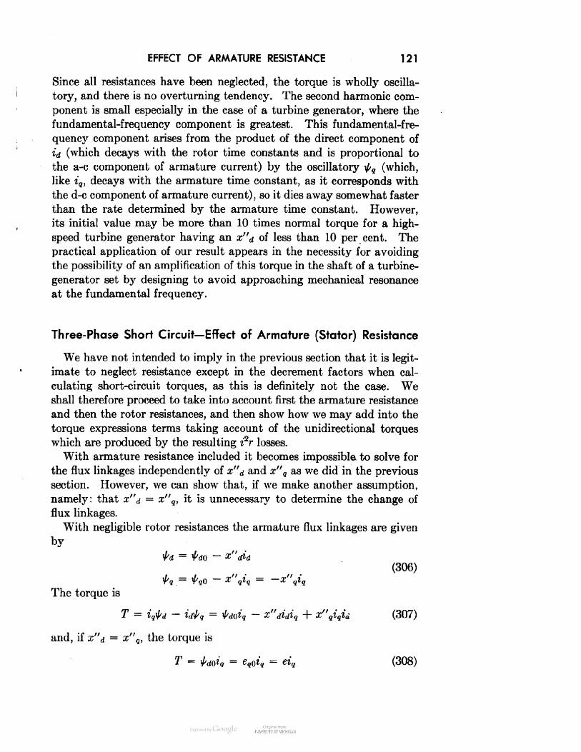
EFFECT OF ARMATURE RESISTANCE 121Since all resistances have been neglected, the torque is wholly oscilla-tory, and there is no overturning tendency. The second harmonic com-ponent is small especially in the case of a turbine generator, where thefundamental-frequency component is greatest. This fundamental-fre-quency component arises from the product of the direct component ofid (which decays with the rotor time constants and is proportional tothe a-c component of armature current) by the oscillatory \}/q (which,like iq, decays with the armature time constant, as it corresponds withthe d-c component of armature current), so it dies away somewhat fasterthan the rate determined by the armature time constant. However,its initial value may be more than 10 times normal torque for a high-speed turbine generator having an x"d of less than 10 per cent. Thepractical application of our result appears in the necessity for avoidingthe possibility of an amplification of this torque in the shaft of a turbine-generator set by designing to avoid approaching mechanical resonanceat the fundamental frequency.Three-Phase Short Circuit— Effect of Armature (Stator) ResistanceWe have not intended to imply in the previous section that it is legit-imate to neglect resistance except in the decrement factors when cal-culating short-circuit torques, as this is definitely not the case. Weshall therefore proceed to take into account first the armature resistanceand then the rotor resistances, and then show how we may add into thetorque expressions terms taking account of the unidirectional torqueswhich are produced by the resulting i2r losses.With armature resistance included it becomes impossible to solve forthe flux linkages independently of x"d and x"q as we did in the previoussection. However, we can show that, if we make another assumption,namely: that x"d = x"q, it is unnecessary to determine the change offlux linkages.With negligible rotor resistances the armature flux linkages are givenby(306)- Xgtg = -The torque isT = iqtd — idfrq = ta0iq ~ x"didiq + x"qiqid (307)and, if x"d = x"q, the torque isT = fa0iq = eg0iq = eiq (308)

122 SHORT-CIRCUIT TORQUESThus it is only necessary to find iq. This is given by the second equa-tion 115 of Chapter 4 [with Xd(p) = xq(p) = x"d = x"q] as(x"dp + r)el•' = *' „. (309)or(p + a)1^a-^l (310)wherer 1Z d .toSore (p + a)l*, = (312)x"d (p + a — j)(p + a + j)By solving this operational expression and multiplying over by e (seeequation 308), we find for the torque as a function of time:e2T = eig = .7T5 5 [«~° Vd sin t - r cos i) + r] (313)Z d + 1*This expression for torque shows two things: (1) that for negligiblerotor resistance the fundamental-frequency torque decays with the arma-ture time constant (I/a) = Taz, and (2) that the maximum unidirec-tional or overturning torque occurs when the armature or external loadresistance r becomes equal to x"d. The value of r for maximum T maybe found by setting dT/dr equal to zero and solving for r. This alsoshows thate21 max (unidirectional) „ .. ("14)2z"dwhich for a subtransient reactance x"d of 10 per cent becomes 5 timesnormal.Another useful form of the torque expression ise2 [ r ]T = eiq = — «-"' sin (t - tan"1 a) -f — • (315)Z L Z\whereZ = Vx"d2 + r2 (316)This form of the torque equation brings out the fact that the over-turning torque is of the form i2r, where i = e/Z is the fundamental-frequency component of armature current which does not decay withthe armature time constant and so must decay only as the rotor (average)

EFFECT OF ROTOR RESISTANCE 123flux decays. We must note that, in calculating the armature i2r loss,it is only the a-c component of current and not the d-c component thatcontributes to the torque.A final point that should be noted is that the magnitude of thefundamental-frequency component of torque is only very slightly affectedby moderate values of armature resistance and thus may be calculatedvery nearly correctly neglecting resistance.Three-Phase Short Circuit— Effect of Rotor ResistanceWe now consider only the resistances in the rotor circuits. Thearmature currents are given by equations 122 withe,K> = 0andw = 1.0id = 2 1(317)peIt is evident that, since equations 301 for the changes of flux linkagesare still valid, we could also have derived equations 317 directly fromthe expressions:(318)xq(p)which follow from equations 1 13.We shall assume only a single rotor winding in each axis so that(see equation 150)+ xdr(319)+ Xqwhere x'd and x'g are the short-circuit reactances of the direct- andquadrature-axis armature circuits, respectively, and Td and Tg are the

124 SHORT-CIRCUIT TORQUESrotor open-circuit time constants (or the ratio of rotor-coil self-induct-ance to resistance).The operational impedances 319 may for convenience be put intothe forms:(P + a')'- — . — -ay(p) = x'(P + a)(320)whereg\yj •«• q .a' Xdxd1a =aTd1ax'd~r;1Poi XqT•* eX gl nX'a7",and T'd and T'q may be called the rotor short-circuit time constants.The currents becomee (p + a)(321)p(p + /3)Evaluating these operational expressions, we obtain1 v". "• / tt v** j/*. \« i j*d = ^ b + (-a')(1 + O« +(*'-;x-2) + (7T7]and ^ . , . ^°^^;*9 = — ^- e~ft/t H ; ——r H ; r——r (323)orr x'jT2^ i(xd ~ x'd) e~"'j - (xd + x'dT2d) cos t + (xd - x'd)Td sin t! Xd J(324)a* + x'2T2x q -\- x q ± q[- (xg - x'q)Tqe-ft't + (xq + x'qT2q) sin t + (xq - x'q)Tq cos t] (325)To aid in the interpretation of these current equations we may notethat the coefficients are simply related to the standstill impedances of

EFFECT OF ROTOR RESISTANCE 125the machine as measured from the armature terminals at normal fre-quency. This may be shown as follows.The standstill impedance of the machine viewed from the armatureterminals varies from the direct-axis value to the quadrature-axis value,depending on the relative position of the rotor. The direct-axis imped-ance at normal frequency w = 1, expressed in the usual complex-numbernotation of a-c circuit theory, is, . . ,. -x'dTd+jxdP3WP) = JXd(3) = — , , ._ -1 + jTdx-x'T+x x'dT2d)= Rd+ jXd (326), dwhere(327)xd + x'dT2dandm 2«£ fa - a'd)rdZ2d~*2d + *'d2:T2. (>U>)dxd + x'dT2d'22x'd2T(330)with similar relations for the quadrature-axis impedance.Substituting these expressions, and the similar quadrature-axis ex-pressions, in the current equations 324 and 325, we findC €id = — + -5- [RdT'd(ra'1 - Xd cos * + Rd sin t]xd Z2d(331)iq = ~Y l-R^-P'* + Xq sin t + Rg cos t]Z qor, finally,. e eRdT'did = h —~— ee / Xd\. ° H sin [t — tan — IZ2d Zd \ Rj(332)eRg -«~^'' + — cos (t - tan"1 — )Za \ RJ

126SHORT-CIRCUIT TORQUESThe final forms of id and iq are easily recognizable as the currents thatwould result from application of proper voltages to electric circuitshaving the impedances Zd(p) = pxd(p) and Zq(p) = pxq(p). In fact,we can see from equations 318 and 301 thatid ==pxd(p)1 = H1 = Hsin tpxd(p)COSt1 =1 =sin t-Zd(p)COSt-Zq(p)(333)This concept is of considerable value, since it enables us to compute idand iq by familiar circuit methods without necessarily conforming toDIRECT AXISTd 5 xffd / 'ItQUADRATURE AXISZq(p)« pXq(p)
FIG. 14. Synchronous-machine circuitssome conventional way (such as equations 319) of representing the opera-tional impedances. In the present case the final answer (equation 332)is obtainable directly and very simply from equations 333, by noting(1) that the fundamental-frequency component of iq may be writtenin this form practically by inspection, (2) that the magnitude of theexponential component follows in order to make the initial value of iqzero, (3) that the time constant 1//3' can be seen from the circuit (whichsimply consists of two magnetically coupled circuits, the primary havingno resistance, see Fig. 14), and (4) that id, in addition to having itsfundamental-frequency component obtainable by inspection, must bewholly obtainable by integrating iq (and changing subscripts) under thecondition that its initial value must also be zero.

DISCUSSION OF THREE-PHASE SHORT-CIRCUIT TORQUES 127Finally, we must keep in mind that this circuit concept, although notat all dependent on the form of the rotor circuits, depends on the assump-tion that armature resistance is negligible.After this preliminary skirmish with the armature currents, we pro-ceed to the torque, using again the familiar expression:T = i^d - i^q (62)where the currents are given by equations 331 and the (total) flux link.ages are\l/d = e cos t(303)\l/q — —e sin tSubstituting equations 303 and 331 into equation 62, we find, forthe torque:e2/Rd Rq\ /I RdT'd ,\ e2RqT = -^ + -- + e2 — H -- — « sin * -- e~? cos t/I{ —\xd2 \Z2d Z\ \xd Z2d / Zqe2 f 1 / , Rq\ 1 / , Rd\~\+ - — sin I 2t + tan"1 -? ) - — sin ( 2t + tan"1 — ) (334)2 LZq \ Xq/ Zd \ Xd/JDiscussion of Three-Phase Short-Circuit TorquesWe have now derived three expressions for the torque on a synchro-nous machine following a three-phase short circuit:Equation 305, in which all resistances are neglected.Equation 315 (or 313), in which all rotor resistances are neglectedand in which rotor saliency is also neglected.Equation 334, in which armature resistances are neglected.Let us now examine these expressions in the light of our previousdiscussions of the physical phenomena occurring in the machine and tryto arrive at a practical method of calculating torque for any particularcase including both stator and rotor resistances simultaneously.It is evident that the torque may be separated out into four com-ponents.1. A fundamental-frequency component of torque depending prin-cipally on the direct-axis subtransient reactance.2. A unidirectional component of torque proportional to the rotori2r losses, where i is the a-c component of rotor current or the d-c com-ponent of stator current.3. A unidirectional component of torque proportional to the stator(armature) i2r losses, where i is now the a-c component of armaturecurrent.

128 SHORT-CIRCUIT TORQUES4. A double-frequency component of torque depending on the sub-transient saliency.These are discussed in turn below.FUNDAMENTAL-FREQUENCY COMPONENT OF TORQUEThis component of torque arises from the product of the direct com-ponent of id (or the fundamental-frequency component of armature cur-rent) by the fundamental-frequency component of \l/q (or a constantcomponent of armature flux linkage), entirely in equation 305 and prin-cipally in equation 334. In equation 334 there is also a small com-ponent arising from the product of the direct component of iq and thefundamental-frequency component of \l/d. In equation 315, when arma-ture resistance was considered, we found this same fundamental-fre-quency torque as the product of the initial direct-axis flux linkage td0by the fundamental-frequency component of iq. At first sight this mayseem disturbing, but we must remember that for convenience we oper-ated on the original torque formula 62 to obtain equation 308 by can-celing out certain terms. Thus, all the effect of i^/q was canceledagainst part of the effect of iqtd. We should not therefore depend onequation 315 for a physical interpretation of the origin of the torquecomponents.The initial magnitude of the fundamental-frequency component oftorque is practically proportional to l/x"d. If all resistances are neg-lected, this relation is seen to be exact (equation 305); if armature re-sistance is included (equation 315), it becomes proportional to l/Z(where Z = V x"d2 + r2); and, if rotor resistance is included (equa-tion 334), it becomes practically proportional to l/Zd (see equation 328).This last relation is not exact but can be seen approximately as follows:The initial magnitude of the coefficient of e2 sin t in equation 334 is1 RdT'd XdXd / d / dand the initial magnitude of the coefficient of e2 cos t is Rq/Z2q. Thecombined coefficient of the fundamental-frequency term, which is thesquare root of the sum of the squares of (Xd/Z2d) and (Rq/Z2q), evi-dently approaches l/Zd if Rq/Z2q is not too different from Rd/Z2d.Moreover, we are allowed considerable latitude since Rg/Z2g will usu-ally be much smaller than Xd/Z2d.The decrement factor of the fundamental-frequency term is obtain-able by noting that its two principal factors are the d-c component ofarmature flux linkage, which decays according to the armature time

DISCUSSION OF THREE-PHASE SHORT-CIRCUIT TORQUES 129constant Ta3, and the fundamental-frequency component of armaturecurrent, which for usual values of machine resistances decays practi-cally in proportion to the average direct-axis rotor flux linkages. Forthe synchronous machine with both a field and an amortisseur the decayof the fundamental-frequency component of armature current may beseen in equation 146 of Chapter 4. Thus the fundamental-frequencycomponent of torque may be written approximately asrfund = eh-'/T°> \(~ - i-) rt/T"« + (4- - -). \X d X d/ \X d Xd/or!Tfund = e-'/T°8 sin t S e-'/r.i sin tX d Ad1"-t/T'di+sin txd.(33G)nt(337)where F is the rotor flux linkage as a fraction of its initial value:X^dXd / xd\ x'd t \ x'd xd /(338)It should be noted that, if the armature resistance is great enough toaffect the impedance, as in equation 315, the fundamental-frequencycomponent of torque will disappear very rapidly. For example, ifr/x"d = 0.1, Z/x"d is only 1.005, or still very close to unity, but thetime constant of the armature flux linkages is only 10 radians or 1.6cycles. Thus at a time Y\ cycle after the short circuit (when accordingto equations 305, 315, or 334 this torque is near its first maximum)it has already decayed to t~T/20 = 0.855 times its initial value of e2/Zd.More nearly exact expressions for torque could be constructed by con-sidering also the quadrature component of rotor average flux as repre-sented by the cos t term of equation 334, but this seems hardly justifiedin view of the uncertainties involved.FIRST UNIDIRECTIONAL COMPONENT OF TORQUE (ROTOR i2r)This torque is given by the first term of equation 334. This termmay be written asTrotor = WdRd + i\Rq) (339)whereid = ^ t, = ^- (340)&d %qand is seen to be the average of the losses in the direct- and quadrature-axis rotor circuits. Moreover, it is obtained as the average value of thedifference of the products [id — (eRd/Z2d) sin t by \/,, = — e sin t] and

130 SHORT-CIRCUIT TORQUES[iq = (eRq/Z2q) cos t by ^d = e cos t]. All of these terms correspondto d-c components of armature current and flux linkages or to funda-mental-frequency components of rotor currents and fluxes. In effect,it is just as though the armature were supplied with d-c excitation sothat the resulting rotor losses must be supplied by mechanical torque,while the stator i2r losses are supplied by the decay of the energy ofthe stator magnetic field. Since all the factors of the torque decay withthe armature time constant Ta3, the torque itself must decay with halfthis time constant, so that finally2Z2dif the resistance components are small, this becomes approximately.1 .*If we consider a turbine generator, we may have approximatelyZd = Zq = x"d = x"q = 0.10Rd = Rg = 0.03Ta3 = 60 radians (about 10 cycles)c = 1.0Then the rotor i2r torque isTrotor = 3.0 e-'/30This torque has initially a very large value but rapidly decays. It mayin certain cases (e.g., where the shaft natural frequency is rather small)contribute appreciably to shaft torque. As far as the motion of themachine is concerned (e.g., in the calculation of transient stability), thistorque is appreciable only for the first 10 cycles, by which time it hasdecayed to about 0.3, or 10 per cent of its initial value. We may estimateits effect on rotor speed as follows. If we take the rotor moment ofinertia M equal to 6000 radians, we may write the torque equation:= -Trotoror6000pu = -3.0e-'/3°orc °°O e-"80*J0-.dHhr= -0.015= -1.5%total change of speed due to rotor i2r losses

DISCUSSION OF THREE-PHASE SHORT-CIRCUIT TORQUES 131For a waterwheel generator the rotor i2r loss is much smaller. In thiscase we might haveZd = x"d = 0.25Zq = x"q = 0.35Rd = 0.02Rg = 0.04Ta3 = 100 radians (about 16 cycles)e = 1.0whence= 0.323* -'/5°The total change of speed following short circuit, due to this COm-ponent of torque, may be calculated as before, but now using a smallerrotor inertia of M = 3000, such as may be more nearly correct for awaterwheel generator. In this case,0A<° = ~ 3000 (50) = ~or about one third as great as for the turbine generator consideredpreviously.These calculations are of course only approximate, especially in viewof the fact that we have in all of our short-circuit calculations assumedconstant rotor speed.SECOND UNIDIRECTIONAL COMPONENT OF TORQUE (STATOR /2r)Most of the remarks about the stator i2r losses that follow are basedon the analysis made above, neglecting saliency. It can be shown thatthere is a very small additional unidirectional torque produced by statorresistance in conjunction with saliency (i.e., if x"d 7* x"q) which decayslike i2d^. For the present, however, we want to confine ourselves tocases wherein the mathematics is sufficiently simple so as not to' obscurethe physical reasoning.As we have remarked previously, it is not possible to see, from theformula T = td0iq, the actual origin of the torque. Instead we mustsee directly from equation 315 that the unidirectional component arisesas i2r, where i is the a-c component of armature current. Indeed, byobtaining only the steady-state solution, it becomes evident that theonly torque on the machine arises as a resistance load torque.In general, i2 = i2d + i2q for the direct components of id, iq, or thefundamental-frequency component of armature current, and, if saliencyis not neglected, the direct components of id and iq are given by equa-tions 147 to 149 of Chapter 4.
132 SHORT-CIRCUIT TORQUESWe may express the d-c component of torque asr.t.tor = i2r = (?d + i\)r (343)where, if the armature resistance r is large (as in the application of aload, rather than a short circuit), the currents are calculated as de-scribed in Chapter 4, Short Circuit with Armature Resistance, includingequation 157, and, if the armature resistance is small, the component iqbecomes negligible (see equations 147-149) and id may be obtained as(see equations 145, 146, and 338).eF«. - ^ (344)so that the torque ise2F2Tstator ^ —i r (345)X dFor a large synchronous generator the armature resistance is not likelyto be greater than 0.3 per cent so that, for a terminal short circuit atnormal voltage, the armature loss torque is not nearly so great as therotor loss torque. On the other hand, it may persist for a much longertime.If we take for a turbine generator the parameters:r = 0.002x"d = 0.10x'd = 0.125xd = 1.25e = 1.0the subtransient value of the stator loss torque is 20 per cent, whichdecays very rapidly to the transient value of 12.8 per cent and thenmuch more slowly to the steady-state value of 0.128 per cent.For a waterwheel generator withr = 0.003x"d = 0.25x'd = 0.333xd = 1.0we have Subtransient T = 4.8%Transient T = 2.7%Steady state T = 0.3%

DISCUSSION OF THREE-PHASE SHORT-CIRCUIT TORQUES 133The fact that the subtransient component of torque disappears veryrapidly means that we shall actually obtain the maximum overturningtendency not when r = x"d but when r is made equal to the transientreactance x'd. Since ordinarily the transient reactances of the directand quadrature axes are widely different, we should include the effectof saliency to find a sufficiently accurate value. Referring to equation148, the transient torque including the effect of saliency isT'•If - ,stator — (.<• dy' /t i 2\2(x dxq + r2YBy differentiating T" with respect to r, setting dT'/dr = 0, and solvingfor r, we findfor maximum transient unidirectional torque. The table below showsthe values found for r/x'd for various ratios of xq/x'd.1 1.OO2 1.064 1.30It therefore appears that x'd rather than x'q is the more importantfactor in determining the maximum transient load torque. A similareffect may also be noted in the power limit of a salient-pole machinetied to a power system, as in that case also the direct-axis reactance isthe more important.DOUBLE-FREQUENCY COMPONENT OF TORQUEThe double-frequency component of torque arises from the productof the direct components of armature current and flux linkage, just likethe rotor i2r loss torque. It may be see.n from equation 334 to dependin magnitude on the direct- and quadrature-axis standstill (normal-fre-quency) impedances; its decrement factor is the same as that of the rotori2r loss torque. If all resistances are small, we may write approximately— ) e-2t/T°ssin 2t (346)^ q X d'This component of torque is not particularly significant because it isovershadowed by the much larger double-frequency component whichmay arise on a line-to-line short circuit, where there is in effect saliencyon both stator ancf rotor and all harmonic torques are present. For a

134 SHORT-CIRCUIT TORQUESline-to-line short circuit, the fundamental-frequency torque and the rotori2r loss torque may be very nearly the same, the second-harmonic torquemay be greater, and the stator i2r loss torque may be smaller, than fora three-phase short circuit. Since the armature i2r loss is ordinarilyrather small, the line-to-line case may be the more severe.Finally an approximate expression for the complete torque of a salient-pole synchronous machine during a three-phase short circuit with allresistances rather small, is.* .* fund l .* rotor izr I •• stator *'2r ~T~ 1 2d harmonic= (337) + (342) + (345) + (346)p \-2l/Taix"d 2\x"dF2rF2r 1/1 1 \ 1H o + ~ I ) «~ sin 2<_// 2 O\T." 'r"./X rf _ \X a X d/ J(347)where F is given by equation 338.Expressions valid for either large rotor or stator resistances may beobtained from equations 334 or 313 or, as mentioned at the beginningof the chapter, derived directly from exact solutions for the currentsand flux linkages. In nearly all cases, however, it will be sufficient touse the approximate expression above.Line-to-Line Short CircuitIn our calculation of the torques resulting from a line-to-line shortcircuit we shall assume, as before, that the short circuit occurs from noload, that constant (unit) speed is maintained during the period of in-terest, and that stator and rotor resistances may be neglected in com-puting the alternating components of torque. Thus resistances will beused only to determine decrement factors and to estimate, as in thethree-phase case considered previously, the unidirectional componentsof torques.GENERAL PROCEDURE21The synchronous machine is considered to have a main field windingand one amortisseur circuit in its direct axis and one amortisseur circuitin its quadrature axis. Thus both subtransient and transient effectswill be obtained.The armature current and rotor mmf are given by the method andequations of Chapter 5, which are reviewed briefly below. The initial

TORQUE 135values, before the effect of decrements is appreciable, are determinedby the open-circuit armature voltage before the fault, the rotor positionat the instant of short circuit, and the machine subtransient reactances.The armature mmf is resolved into its direct- and quadrature-axis com-ponents and is expressed as odd- and even-harmonic series. The averagecomponent of the direct-axis current (or the fundamental componentof the actual armature current) induces transient direct currents in thedirect-axis rotor circuits; all other harmonic components induce alter-nating currents in the rotor circuits. Consequently, following the shortcircuit the d-c component of rotor excitation is increased from its valuejust before short circuit to a new value which includes the componentsinduced in the rotor windings by the armature current. The decay ofthe induced d-c components of rotor excitation and that of the odd-seriescomponents of armature current are determined by the decrement factorsof the direct-axis rotor windings.We assume that the decay of the additional rotor excitation may berepresented with sufficient accuracy by two decrement factors, one ap-plying to the decay of the induced direct current in the amortisseur,and the other applying to the decay of the induced component of directcurrent in the field. A rotor-linkage factor F represents the total averagerotor linkages at any time after the short circuit as a fraction of therotor linkage just before short circuit.The average flux linkage in the short-circuited armature windings ismaintained by the induced direct component of armature current. Thisflux linkage decays with the direct component of armature current. Forconvenience, an armature flux-linkage factor A is introduced, where Arepresents the average flux linkage of the short-circuited armature wind-ings as a fraction of the flux linkage of these windings just before theshort circuit. The even-harmonic series of the armature current andthe odd-harmonic series of the rotor excitation decay in proportion to A.TorqueAs before, the torque is given by the general expression:T = tdiq - tqid (62)But, by equations 37 and 38, or by equations 24-26, the flux linkagesmay be expressed in terms of the coil currents astd = Xafdifd +Yq =for a machine with a single amortisseur circuit in each axis. Moreover,

136 SHORT-CIRCUIT TORQUESthe changes in rotor excitations may be expressed in terms of the statorcurrents by equations 215 and 216 asXaidild = (Xd ~ x"d)id(349)= (xq - x" g)iqif resistance can be neglected.In the quadrature axis all the induced currents are alternating, andthere is no initial flux, so that we may write\l/g = (Xq — X"g)iq — Xqtg = — X" gig (350)a result that would have been obvious offhand. We seem to have gonearound a circle but shall see that the same procedure will lead to adifferent result in the case of the direct axis.In the direct axis the initial flux linkage is fa0 so that the total fluxlinkage isfa = fa0 + (xd - x"d)id - Xdid (351)if rotor resistances can be neglected. However we have seen in Chapter 5that rotor resistances cannot be neglected in the case of the d-c com-ponents of id and \l/d. Equation 351 must therefore be modified so asto give correctly the decrements of the d-c components.The alternating components of fa are always given more or less cor-rectly by equation 351, but the direct components are evidently givenapproximately by the relations:Initially, subtransient,t"d = fa0 - x"di"d (352)Next, transient,*'d = fa0 - x'di'd (353)Finally, in the steady state,fas = fa0 — Xdid, (354)Since we are trying to derive a means of correcting equation 351, weshould express these flux linkages in the form:t" , i = fa0 ~ x"di"d (352)t'd = fa0 ~ x"di'd + (x"d - x'd)i'd (355)fa, = fa0 - x"dids + (x"d — xd)id, (356)which brings out the fact that, since using the actual current id insteadof the average currents i"d, i'd, and i,is will affect only the alternating
TORQUE137components of \pd, we may still multiply the armature current id alwaysby x"d if we modify ^m so as to change it intol+do + (x"d - x'd)i'd]bf'do + (x"d - Xd)ids]for the transient condition and intofor the steady-state conditionIn these relations all the currents and flux linkages are only the average(d-c) components. On this basis it may be seen from the discussion inChapter 5 (from equations 217 to 225) thatEid =tdOandIdsx'd + x2 x'd + x2E idoXd + x2 xd + x2(357)(358)Substituting these expressions for average current into the expressions352, 355, and 356 for average flux linkages we obtain, for the sub-transient, transient, and steady-state average flux linkages:+"d = t,dOVd = "Pdlfas = ^dO- x"di"d(352)~x"d + x2~ x'd + x2 .- x"di'd(359)~x"d + x2- Xd + x2 ~- x"did.(360)The required variation of tda in equation 351, so that the armaturecurrent may always be multiplied by x"d to obtain id, is therefore fromtototdOtdOtdOinitially(x"d + xa\\x'd + x2J(X"d + x2\\xd + x2 /in the transient statein the steady stateTherefore the effective value of flux linkage to be added to —x"did toobtain \frd may be represented as*J(i-^)L\ x'd + x2 /\x'de-(/r'*<M>+ x2 x"d + x2^+ x2 xd + x2-i/t' . x d ~r x2e l" d (M) -|-Xd + x2(361)

138 SHORT-CIRCUIT TORQUESThe complete expression for flux linkage fo may therefore be written as- x"did (362)where F is a factor describing the flux-linkage decay, and given by(according to equations 352, 359, and 360)F-.1-"x'd + x2x2 xd + x2 / xd + x2(x"d + x2\l - - - 1\xd + x2 /(303)The factor F is seen to be of exactly the same form as the F of equa-tion 338 for the rotor flux linkage in case of a three-phase short circuitthrough an external reactance x2. It will also be recognized as occurringin equation 225 as a factor in the odd-harmonic component of armaturecurrent during a line-to-line short circuit, where it represents the decayof the rotor mmf .The expressions 350 and 362 for \l/q and \l/d may now be substitutedinto the torque equation 62 to obtainT = i^d0F + (x"q - x"d)idiq(364)= i^d0F + (x"g - x"d)id]The currents id and iq may be obtained from ia and ip by equations217 and 175 (and also adding in the decrement factors as shown inequation 225).2E(F sin 6 — A sin 00) sin 6id — ie sin 6 = -x"d + x"q - (x"d - x"q) cos 20(365)2E(F sin 6 — A sin 00) cos 0ia = ia cos 0 = - — — --x"d + x"q - (x"d - x"q) cos 20where F is given by equation 363 andA = e~'/T°<'-o = armature decrement factorSubstituting equation 365 in equation 364 and noting that \l/d0 = E, wefind, for the torque:2E2F(F sin 0 - A sin 00) cos 0T =x"d + x"q - (x"d - x"q) cos 202(x"q - x"d)[E(F sin 0 - A sin 00)]2 sin 20'[x"d + x"q - (x"d - x"q) cos 20]2(366)

TORQUE 139For the particular case of zero initial armature flux linkage, 60 — 0,so that sin 00 = 0, and the torque equation 366 reduces to2x"qE2F2 sin 26T" = [x"d + x"q - (x"d - x"q) cos 26}2Equation 366 may be used to compute the instantaneous torque atany time after short circuit. However we also want to express thetorque in terms of its harmonic components, since this may be the bestform in which to use it to compute the resulting shaft torques. Thismay be done by resolving 366 into a Fourier series, whence we obtain2E2xd +X [- cos 6 + 36 cos 36 - 5b2 cos 56 + 7b3 cos 76 ---- ]x x"d - x2 . .,A2 - sm2 00x d + x2 x2X [sin 26 -2b sin 40 + 362 sin 66 ---- ] (368)whereX2 + X"das in Chapter 5, equations 194 and 203.It is evident from equation 368 that all the odd-harmonic componentsof torque will disappear as the trapped armature flux linkage decays.On the other hand, only one component of the even-harmonic serieswill disappear, leaving the even-harmonic series as given by equation367 for the case of short circuit with zero initial armature flux linkage.The part of the even-harmonic torques proportional to the square ofthe armature linkages (A2) appears only when the subtransient react-ances in the direct and quadrature axes are not equal (see equation 366) .This may be seen also from equation 368, since, if x"d = x"q, thenx2 = x"d also. This component is a reluctance torque caused by thevariation in equivalent permeance which the rotor presents to thetrapped armature flux. Similarly the part of the even-harmonic torqueproportional to the square of the rotor flux linkages is caused by thevariation in equivalent permeance that the stator presents to the rotorflux.The maximum fundamental-frequency torque, immediately followinga short-circuit with maximum armature flux linkage, is 2E2/(x"d + x2).

140 SHORT-CIRCUIT TORQUESThis may be compared to the fundamental-frequency torque for a three-phase short circuit (from equations 305) of E?/x"d and shows that thiscomponent may be just as great for a line-to-line fault as for a three-phase fault. In case of a turbine generator, the reactances are low sothe torques are large. For example, x"d and x2 may both be only10 per cent, whence the magnitude of the fundamental component oftorque will be 10 times base torque for either type of fault. For thiscase the three-phase fault has no second-harmonic terms whereas theline-to-line fault (equation 368) has a second-harmonic torque ofx2/(x"d + X2) = /4 times the fundamental, or 5 times base torque.For a salient-pole watenvheel generator, with x"d = 0.25, x"q = 0.35,and x2 = 0.30, a comparison of the three-phase and line-to-line torquesgives:SHORT-CIRCUIT TORQUESFund.2d HarmonicThree-phase4.00.57Line-to-line3.642.59It is of interest that the quadrature-axis reactance does not affectthe fundamental-frequency component of torque in case of the three-phase fault, so that increasing x"q actually increases the maximumtorque by adding a second harmonic.As a further illustration of the magnitudes involved, line-to-line short-circuit torques have been calculated 21 for a salient-pole machine havingper-unit constants, as determined by test, ofX,l=0.615,x'd = 0.207, x"d = 0.148xq=0.412,x'q = 0.412, x"q = 0.367'Ta=40,T'd = 470, T"d = 14.5Hence,x2 =b =Vx"dx"q = 0.233andX2 — X"d= 0.223x2 + x"dFigures 15 and 16 show the line-to-line short-circuit torques for thismachine with maximum and with zero initial armature flux linkages,respectively, as computed by equation 366.From the standpoint of the design of the machine and of its founda-tions, it is sufficient to consider the case of maximum initial armatureflux linkage, since this includes all the possible torques. For the ma-

TORQUE141chine of Figs. 15 and 16 the peak value of torque is nearly 12 timesrated torque with maximum initial armature flux linkage, while it isonly 4 times rated torque with zero initial linkages. However, it is notnecessarily the maximum electrical torque that is the ruling factor, asFIRST THREE CYCLESSTEADY STATE
15. Single-phase short-circuit torque, maximum initial armature flux linkagesthe different harmonic components of electrical torque may be very dif-ferently amplified (or reduced), depending on the shaft torsional naturalfrequencies and on the generator and turbine rotor inertias, before ap-pearing as shaft torque.Note that, although we have considered resistance in computing decre-ments, we have neglected resistance as far as the magnitudes and phasesof the currents and fluxes are concerned. Thus, equations 366, 367,and 368 give more or less correctly only the alternating components ofshort-circuit torque.The direct or load components of short-circuit torque must be cal-culated, as in the three-phase case, from the stator and rotor i2r losses.FIRST THREE CYCLESTENTH CYCLE
Fig. 16. Single-phase short-circuit torque, zero initial armature flux linkagesJust as in the three-phase fault discussed above, only the odd-harmoniccomponents of armature current are to be used in computing the statori2r loss.On the other hand, both odd- and even-harmonic components nowaffect the rotor i2r losses. The proper values to use are best seen fromthe point of view of symmetrical components (i.e., forward and back-ward rotating mmf's). However, before the discussion of load torquewe shall first consider other types of short circuit.
142 SHORT-CIRCUIT TORQUESOther Types of Short CircuitIt should be evident that the arguments of the previous section, bywhich the expressions for direct-axis flux linkage,td = idoF - x"did (362)quadrature-axis flux linkage,*, = -x"qiq (350)and torque,T = iqU/doF + (x"q - x"d)id] (364)were derived do not depend on the kind of short circuit being considered.Equation 364 may therefore be considered as a general equation for thealternating components of torque valid for all faults (including the three-phase fault), and we need only list below the formulas for id, iq, F, and Apreviously derived for each" type of fault in order to obtain the corre-sponding torque for that type.LINE-TO-LINE ON PHASES b-c (Eqs. 369)2E(F sin 6 — A sin 0O) sin 0U = H sin 0 =iq = iff cos 0 =x"d + x"q - (x"d - x"q) cos 262E(F sin 6 - A sin 0O) cos 6x"d + x"q - (x"d - x"q) cos 20( x"d + x2\ „F = I 1 I e ' o «-'>\ x'd + x2/, (x"d + x2 x"d + x2\ _t/T, , X"d + x2\ X'd + x2 Xd + X2 / Xd + x2A = e-'/7,.«-ox"d + x2rn mild(l-l) — 1 dOri mid(l-lt — 1X'd + X2X'd + X2d(l-l) = 1 doTa{l-l) =Xd + X2X2rT = iq [EF + (x"q - x"d)id](The current ip is taken from equation 175 of Chapter 5, with theappropriate decrement factors.)

OTHER TYPES OF SHORT CIRCUIT 143LINE-TO-NEUTRAL, ON PHASE a (Eqs. 370)2E(F cos 6 - A cos 00) cos 0Id = 1'a COS 0 =x"d + x"qiq = —ia sin 0 =f (x"d - x"q) cos 20-2E(F cos 0 - A cos 00) sin 03 + (x"d - x"g) cos 20x"d + x"q(1 —\ x'cd + X2 + Xne~'" dMX"d + X2A = e-i/ra(«-n,x"1 di-n - 1XQx0d(i-n) - 1 d0—1 d I-n — 1X dX'dX0d (I-n) — 1 dOXd + X2 + XQ2X2 + XQ1 o <*-"> ~ "^ - 1 -2r + r0T = iq[EF + (x"q - x"d)id](The current ia is derived from equations 186 and 185 of Chapter 5.)DOUBLE-LINE-TO-NEUTRAL, ON PHASES b, cEid = ia cos 0 + ip sin 0 = — [2x"qF cos 0(Eqs. 371)- (x"d + x"q)A cos 00 + (x"d - x"q)A cos (20 - 00)] cos 0E+ - [(2x"q + 4x0)F sin 0 - (x"d + x"q + 4x0)B sin 00+ (x"d - x"q)B sin (20 - 00)] sin 0
144 SHORT-CIRCUIT TORQUESiq = — ia sin 6 -\- ip cos 6F= [2x"qF cos 6 - (x"d + x"q)A cos 0O+ (x"d - x"q)A cos (26 - 60)] sin 6+ - [(2x"q + ix0)F sin 6 - (x"d + x"q + 4x0)B sin 0O+ (x"d - x"q)B sin (26 - 60)] cos 6where D = 2[x0(x"d + x"q) + x"dx"q - x0(x"d - x"q) cos 26]— l/T"€ '/ d (ll-n)p = /_ x"d + xe\\ x'd + xe I/x"d + xe x"d + xA\ X'd + Xe Xd + Xe )Xe =-//7" X d I XeX<J + XeX2X0x2 + x0x"d + XeTil _ raw " *d (ll-n) — * dO —. jX d + XeX'd + Xert mld (ll-n) ~ * ,T,act (ll-n)do———x2 + 2x0r + 2r0X'2■ off (ll-n) —rT = iq[EF + (x"q - x"d)id](The equations for ia and ip used here are obtained from equations241 and 242 of Chapter 6.)

HARMONIC COMPONENTS OF LINE-TO-NEUTRAL TORQUE 145THREE-PHASE (Eqs. 372)Eid = — (F - A cos 0x "dEio = - A sin tx"Xd XdA = e-'/r-x"dTff rpifd3 = 1 dO —7-X'dT' - T' —^ dZ — l M —XdT -X2ia3 — —rT = iq[EF + (x"q - x"d)id]It may be noted that, for the three-phase fault, the currents expressedas id and iq are functions of time t (measured from the instant of shortcircuit) directly rather than of the rotor angle 6 and thus do not dependon the initial rotor angle 6Q (the angle of the direct axis ahead of theaxis of phase a at the instant of short circuit). This has been pointedout in Chapter 4 and is a consequence of the complete symmetry ofthe stator winding. The initial rotor angle determines only the location,and not the magnitude, of the flux trapped in the stator. For all the un-balanced faults, the currents, and consequently the torques depend onthe initial rotor angle and have therefore been expressed as functions of6(6 = 00 + 0. Equations 372 for the three-phase case may be shownto check the alternating components given by equation 347 above.[The equations for id and iq are taken from equations 143 of Chapter 4,with 5 = 0 (no load) and e = E.]Harmonic Components of Line-to-Neutral TorqueIt has already been pointed out that the principal use of the transientelectrical torques that we have been calculating is in the determinationof the resulting shaft torques. The mechanical system involved con-
146 SHORT-CIRCUIT TORQUESsists of the generator and at least one, and possibly two, turbines. It isthus an equivalent mass-and-spring system that has one or more naturalfrequencies of its own. These natural frequencies will ordinarily be sosmall that components of torque of frequency larger than the secondharmonic (120 cycles in a 60-cycle machine) will be appreciably sup-pressed, and the fundamental-frequency component will be by far themost important term. As the various harmonic components of torqueare differently amplified in the mechanical system, it is of interest tohave the torques for all types of faults expressed directly in terms oftheir harmonic components, as has already been done for the three-phase and line-to-line cases.The line-to-neutral case is easily written down, since it may be ob-tained directly from the line-to-line case (equation 368) by simplyreplacing x"d, x"q, by x"d + x0/2, x"q + *0/2, and replacing 6 by(6 + 90°). This was pointed out in Chapter 5 and is also evident fromequations 369 and 370 above.The torque for a line-to-neutral fault is thus2E2f —Xd + X2 + X0[FA cos 00(sin 6 + 360 sin 36 + 5b20 sin 50 + 7b30 sin 76 H ---- )/ „ Z2 + *0/2 .8 x"d-X2 \- [ F2 -- A2 - cos2 00 ) X\ x"d + x2 + x0 x2 + x0/2 /(sin 20 + 260 sin 40 + 3620 sin 60 H ---- )] (373)wherex2 - x"dx d ~r x2 + XQand x2 is defined by equation 204 of Chapter 5.The closed form for the torque, corresponding to equation 366 for theline-to-line case, may also be written down in the same way. A com-parison of equations 373 and 368 (or of 370 and 369) shows that thealternating components of torque following a line-to-neutral short cir-cuit are always smaller than those for a line-to-line short circuit at acorresponding initial rotor angle. The line-to-neutral case thus doesnot have to be calculated so far as these alternating components areconcerned.If the machine neutral were grounded through a resistor having aresistance of the same order of magnitude as the machine transientreactance (i.e., 10 or 20 per cent), a large unidirectional component of
UNIDIRECTIONAL COMPONENTS OF TORQUE 147torque might exist. This kind of resistance grounding is not used ordi-narily and will be very exceptional.A similar development of the torque in a Fourier series could be carriedout for the double-line-to-neutral fault but has not yet been completedfor the general case. The Fourier series for the currents are given inAppendix A.Unidirectional Components of TorqueIn the determination of the unidirectional components of torque forunbalanced faults, the effect of armature currents other than the funda-mental and d-c components will be negjected. This is really on accountof the difficulties of calculation but also may be justified by the rela-tively small magnitudes of these torques as a whole, by the negligiblesubtransient saliency (which produces the higher harmonics) in the caseof turbine generators where the torques are greatest, and by the un-certainty inherent in the available values of the resistances.As stated previously, the even-harmonic currents (now only the d-ccomponents) produce a rotor i2r loss by acting as d-c excitation on thestator just as in the case of the three-phase fault, while the odd-harmoniccurrents (now only the fundamental) produce not only a stator i2r lossbut also a rotor i2r loss. This additional rotor i2r loss is caused by thenegative-phase-sequence component of armature current and is bestseen from the viewpoint of symmetrical components. Our first step istherefore to derive an expression for unidirectional or average torque interms of symmetrical components.We have shown in Chapter 2 that the torque T is given in terms ofd- and g-axis quantities (i.e., in terms of axes fixed in the rotor) asT = i^d ~ i^g (62)By means of the relations 217 for i and the similar relations for \l/:td = ta cos 6 + \{/B sin 6(374)tq = —ta sin 0 + ^ cos 6the torque may be expressed in terms of a and /3 quantities (i.e., in termsof axes fixed in the stator) asT = i&a - *„*„ (375)(We note that the expression for torque is exactly the same in termsof stator axes as in terms of rotor axes. Indeed, since the angle 6 doesnot appear in the result, it is evident that we could have used any otherangle just as well in the substitution equations 217 and 374. This brings
148 SHORT-CIRCUIT TORQUESout the fact that the expression for torque is the same in terms of anyset of two-phase components, regardless of their position relative to themachine and even of whether or not the co-ordinate axes may have anyarbitrary accelerating motion of their own. We may recall the relatedfact noted in Chapter 2 that the form of the armature voltage equa-tions 32 is also independent of the choice of angle defining the referenceaxes.)In equation 375 i, t, and the torque itself are all real quantities.Moreover, since for our present purpose we are concerned only withthe fundamental components of armature current and with the resultingaverage torque, both i and ^ are sinusoidally varying quantities. Forconvenience in calculation and in converting over to symmetrical com-ponents (see Chapter 6), equivalent complex exponentially varying quan-tities will be substituted for the real sinusoidally varying quantities.For example, the complex quantity,i= (ohas the real part:i = a cos ut — b sin utand i will be used to represent i in the equations. On this basis theaverage torque may be written asTavg = real of [|(i/,*x|»a - iaV)]or(376)These forms may be seen to be valid if the dot product is defined, asin Chapter 3, as the sum of the products of the inphase components ofthe two quantities i and vjf. That is, the average or d-c component of theproduct of two quantities:(a cos cot — b sin ut) times (c cos ut — d sin a>0is %(ac + bd), as may easily be demonstrated, while the dot productof the corresponding complex quantities,(a +#),*"•(«+#).*"is ac + bd, or just twice the required average value. Similarly, it mayeasily be shown by trial that the real part of the product of one com-plex quantity times the conjugate of another,Real of [(a + jb^ut(c - jd)e~ji"]is also ac + bd.

UNIDIRECTIONAL COMPONENTS OF TORQUE 149The symmetrical components may be denned by equations 256 and258 of Chapter 6. Substituting the relations:i« = ii + i2.,. ., (258)and$a = ^1 + +2 /ow(377)tye = —i(+i - +2)into the average-torque equation 376, we obtain for the torque in termsof symmetrical components:7,avg = ir0'fi) -!2•(/♦«) '378)We have next to derive expressions for the flux linkages t|»i, ^2, interms of the currents ii, 12, and the applied voltages, to see the meaningof this expression 378.For the components of flux linkage due to a short circuit, and for asymmetric-rotor machine (as implied by the neglect of higher harmonics),we may writefd = -x d(p) ii = — x(p)id[379)fq = -Xq(p)iq = ~x(p)lqorfd + jfq = -x(p)(i* + jiq)and (380)fd - Jtq = ~x(p)(id ~ jiq)Butid = ia cos 0 + 1^ sin 6iq = —ia sin 0 + iff cos 6or^ + jV« = (ia + jip) cos 6 + (iff - jia) sin 0= (ia+jiff)*~jeSimilarly,id -jiq = (ia ~ jip)*+l6and+d+jiq = (+a + rt/ffh~3'Bfd~jfq = (fa -j+ff)l+jBSubstituting equations 381 and 382 into 380,fa + jfff = -ejex(p)(ia +jip)*-jeor, with p6 = 01,fa + jfff = -X(p - J0))(ia + jiff)(381)(382)

150 SHORT-CIRCUIT TORQUESThis relation also holds for the equivalent complex quantities:+a + jtyp = ~x(p - i«)(ia + 3k) (383a)By equations 256, the symmetrical-component flux-current relation istherefore\|/! = -x(p - i«)ii (383b)Similarly,+« - J+/3 = ~x(p + ju) (ia - jip) (384a)andx|/2 x(p + jco)i2 (384b)Thus in terms of symmetrical components and for a symmetric-rotormachine ^i depends only on il, and 4*2 depends only on i2, just as inthe case of the d-, g-axis quantities. This is in general not true for thea, /3 quantities, as may be seen from equations 383a and 384a above,except when all rotor resistances are neglected. In this case x(p — ju)= x(p + ju) = x" and (again only for a symmetric-rotor machine) v|/adepends only on i„, and typ depends only on ip. This may also be seenby reference to equations 173 of Chapter 5.The flux linkages tyi and ^2 given by equations 383b and 384b areonly the components due to the fault or load. There are also initialvalues, which may be computed for the case of initially open circuit asfollows:The initial d-, g-axis linkages are:XafdfifdVdo = = A = e90rfdtq0 = 0 = ed0Therefore the initial a, /3 linkages are"AaO = E cos 6^(3o = E sin 0The equivalent complex quantities ty aretfl) = -JEJeand finally the symmetrical-component linkages arei|/10 = Ej* = E^u+™. n (388)\|/20 = 0(385)(386)(387)

UNIDIRECTIONAL COMPONENTS OF TORQUE 151Note here that it is necessary to use the equivalent complex quantitiesv|/a,3 instead of the real quantities i/x/3 in order to make vfi20 = 0.In the equations for the changes of flux linkages (383 and 384) wedid not specify the form of i and \l/, but, since we are concerned onlywith the fundamental-frequency components and are using equivalentcomplex quantities, we may let p = ju, whence the ^ — i relationsbecomevh = -1(0)1!(389)^2 = -x(j2u)i2The total flux linkages are, by equations 388 and 389,(390)v|/2 = -x(j2u)i2The average torque (equation 378) now becomesT*ve = ii.Wi0 -jXO)ii] + i2.jx(j2u)i2or, since a;(0) is real,ii .jXO)ii .- 0and(391)This equation may be interpreted by recalling that for a symmetric-rotor machine,r + jx(0) =R!+ jx(G) = Rl + JX, = Zi(392)r + jx(j2u) = Ri + jx(j2u) = R2 + jX2 = Z2where Zi and Z2 are the conventional symmetrical-component positive-and negative-phase-sequence impedances, respectively, Rl = r, and R2= r + [real part ofjx(j2u)]. We may also develop initial-voltage rela-tions, just as we developed the initial-flux-linkage relations. Sinceed0 = 0eq0 = E• '• eaO = —E sin 6os 6ei0 = +jEt>9 = je20 = 0

152 SHORT-CIRCUIT TORQUESSubstituting(e10) forand(Z2 - Ri = R2 - Ri + jX2) for [jxti2u)]in equation 391, we obtainravK = ii.ei0 + i2.(R2= ii.ei0 + (#2 -(394)as a general expression for the average (or unidirectional) component oftorque caused by the fundamental-frequency component of armaturecurrent. The first term is evidently the total power or i2r loss in theequivalent circuit for whichever type of fault is being considered, whilethe second term, depending on the rotor resistance at twice-normal fre-quency and on the negative-phase-sequence component of current, hasto be computed separately and added.The torque formula 394 may also be written as^avg = | U ~Ri + i2 | #2 + io RO + I ia | (#2 — #i)= | i, |2/?! + i2 \2(2R2 - fl,) + | i0 \2R0 (395)where RO is the zero-phase-sequence resistance.From the viewpoint of symmetrical components the fundamental-frequency components of current for the various types of short circuitare:20LINE TO LINE(396)lQ = 0LINE TO NEUTRALii = i2 = i0 = (397)where ZQ(= RQ + jX0 = 3rg + r + jx0) is the zero-phase-sequence im-pedance, XQ is the zero-phase-sequence reactance, and rg is the value ofany grounding resistor between the machine neutral and ground (seeChapter 5). Note that the fault considered is in general from phase ato ground and not to the machine neutral point.

UNIDIRECTIONAL COMPONENTS OF TORQUE 153DOUBLE LINE TO NEUTRAL, CIQfj\ 1~7 i_ yZi2 ~t~ ^0ia = - „ ,° ii = e'° „ (398)Z0Zi + Z0 HTHREE PHASE(399)i2 = i0 = 0The corresponding unidirectional components of torque are, fromequation 395:LINE TO LINEe2i02fl2rr ;2 or> / \r\f\\^avg - | ii | Z«a - T^—^^i^ ^400^LINE TO NEUTRALR0)°|- _ _._ .a1^1 T ^2 T ^0 IDOUBLE LINE TO NEUTRALZ2 + Z0 |2flt + | Z0 \2(2R2 - fit) + Z2 2R0](401)„, _i ave —ZrZ3+ Z2Z0 + 0!THREE PHASEe2R(403)It has become evident from the preceding development that in orderto understand and to compute the loss torques due to fundamental-frequency armature current it is necessary to segregate the current intoits positive- and negative-phase-sequence components, rather than into

154 SHORT-CIRCUIT TORQUESits a, 0 or d, q components. However, since we have already computedthe a, ft components and since it is, to say the least, convenient to haveall terms of the torque formula based on the same quantities, we shallconvert the formulas above into a form based on ia, ip. At the sametime we shall take into account the fact that all these components ofcurrent vary as F (the rotor mmf decay factor), a fact that was notbrought out in the symmetrical-component equations 396-399.The fundamental-frequency components of ia, ip, i0 for the variousfaults have already been obtained in Chapters 5 and 6 asLINE TO LINE (EQ. 218)2EFsin (00 + 0X d .+- X"(404)4 = 0, i0 = 0LINE TO NEUTRAL (EQ. 226)2EFia = — - cos (00 + 0x d + x2+ x0TO = \iaDOUBLE LINE TO NEUTRAL (EQS. 243 AND 244) 2EFla " x"d + 2x0 + V(*"7EF(405)„ X "dX0X d + XQ + ——cos (00 +1)2EFsin (00 + <) (406)"EF- ; - ^-— sin (00 + 0(x2 - x' d)x0x d H --x2 + 2x0
UNIDIRECTIONAL COMPONENTS OF TORQUE 155THREE PHASEEFia = — coS (00 + 0X dEFi& = — sin (60 + 0 (407)x"di0 = 0The equivalent complex forms of the currents are:LINE TO LINEia = 0 (408).io = 0LINE TO NEUTRALX0DOUBLE LINE TO NEUTRALEF„0:2i0 = -iaTHREE PHASEEF• _ _a ~EF.+0 (410)0 =

156 SHORT-CIRCUIT TORQUESFrom these equations for the fundamental-frequency components ofia, ip, we may derive the symmetrical-component quantities ii, l2, bymeans of equations 256 of Chapter 6, asLINE TO LINEEFi2 = \ 0- - &x2EFX d +i0 = 0LINE TO NEUTRALEFii = i2 = i0 = | ia = -7— - ; - ^0+0 (413)a; d + x2 + XQDOUBLE LINE TO NEUTRALEF
„ xdx2x"d + x2-i --N X0'EF(414),X"d + X0-\ --Z2THREE PHASEEF,,=,„ = -,•»•«(415)12 = i0 = 0Except for the time-varying factors (Fej(9o+'>) these currents may beseen to check the values given in equations 396-399.We may also note that in every case the d-c component of the direct-axis current id (the d-c component of iq is zero) is equal to the positive-phase-sequence current i leaving out the exponentially varying factor.

D-C COMPONENT OF CURRENT 157This has already been pointed out for the double-line-to-neutral casein Chapter 6, and may be seen by comparing:For the l-l case, Eq. 219 with Eq. 412For the Z-n case, Eq. 227 with Eq. 413For the ll-n case, Eq. 246 with Eq. 414For the 30 case, Eq. 125 with Eq. 415The relations derived above, among id; ia, ip; and ii, i2, may be usedto evaluate the unidirectional component of torque due to the funda-mental-frequency component of armature current by substituting therelations 412-415, instead of 390-399, in equation 395.Unidirectional Component of Torque Due to D-C Component ofCurrentWe next investigate the rotor i2r loss component of torque due to thed-c component of armature current (which acts as an exciting currentand generates a fundamental-frequency current in the rotor) in com-bination with the rotor fundamental-frequency resistance.For the three-phase short-circuit case this latter torque componenthas been given by equation 339 asT = WdRd + i\Rq) (339)where in this equation id ( = E/Zd) and iq ( = E/Zq) are seen from equa-tion 332 to be the magnitudes of the a-c components of id and iq, re-spectively. These a-c components of id, iq correspond roughly to thed-c components of the actual armature current. Rd and Rq are theeffective rotor resistances viewed from the stator, as shown for exampleby equation 326. From our viewpoint of regarding the d-c armaturecurrent merely as an exciting current, it is evident that equation 339is also valid for the general case, i.e., for any type of fault for whichthe a-c components of id and iq can be evaluated.In the general case the fundamental-frequency components of id andiq may be derived from the even-harmonic components of ia and ip,which have already been obtained and are listed below for the varioustypes of fault.LINE TO LINE4 = 0 2•'• id = ip sin 6 = — ~p ib sin 6V3iq — ip cos 9 = — — ib cos 62V3

158 SHORT-CIRCUIT TORQUESBy equation 193,2EA sin 00 [ 1 Iid (odd) = sin 6 — b sin 6 cos 20 -\x2 12 52EA sin 00 f 1 6 Isin 6 + - sin 6 H1.2 2 Jx2 1.2and withX2 + X"d2EAid (fund) = —; sin 00 sin 0 (416)X d i X2Note that the fundamental-frequency component of id depends notonly on the d-c component of ip but also on the second-harmonic com-ponent if there is subtransient saliency, i.e., if x2 7* x"d. That is, al-though we may obtain the d-c component in the rotor (or stator) fromthe corresponding fundamental-frequency component in the stator (orrotor), the fundamental-frequency component cannot be obtained fromthe d-c component alone.Similarly,2EAsin6Qll 1iq (fund) = COS 0 — 6 COS 20 COS 0 H •x2 \.2 J2EA sin 00 [~ 1 b= cos 0 cos 0 — •x2 12 22EAx"d— sin 00 cos 0 (417)x2(x".-2EAC"q + X2. sin 00 cos 6 (418)Equations 416 and 418 show that the direct- and quadrature-axis com-ponents of current are determined by using the direct- and quadrature-axis reactances, respectively, as positive-phase-sequence reactances justas in the three-phase case but now with the addition of the negative-phase-sequence reactance. Thus the a-c component of id is not equalin magnitude to the a-c component of iq even though there is only asingle d-c component of armature current.

D-C COMPONENT OF CURRENT159LINE TO NEUTRALBy equation 195,2EA cos 0Oip = 0. id — ia cos 0 = +-ftO COS 0-§ia sin 0id = -x2 +x01butb0 =Therefore,Similarly,4EA cos 0O2x2 + x0x2 — %"dx2 + x"d + x0cos 0 + b0 cos 20 cos 0 + •1 b0- cos 0 H cos 0 + •2 22^4^d (fund) — —^« (fund)++Z"d + X2 + X02EA(2x"d + xq)cos 0O cos 0(419)(2x2 + x0)(x2 + x"d + x0)2EAcos 0O sin 0 (420)cos 0O sin 0 (421)x"q + x2 + x0DOUBLE LINE TO NEUTRALThere is no simple yet exact expression for the fundamental-frequencycomponents of id and iq in the general double-line-to-neutral case. Anapproximate expression is^d (fund)iq (fund) = +2EA cos 0O cos 0 2EB sin 0O sin 0x"d + x2 + 4x0 x"d + x22EA cos 0O sin 0 2EB sin 0O cos 0(422)x"q + x2 + 4x0+ Z2In Appendix A this relation is compared numerically with a more orless exact expression, and it may be concluded that it should be satis-factory, since when the corresponding torque is important the degreeof sub transient saliency is usually small (e.g., as in a turbine generator),whereas when the subtransient saliency is larger (as in a waterwheelgenerator) the torque is rather small and therefore unimportant.
160 SHORT-CIRCUIT TORQUESTHREE PHASEBy equations 145, and converting to our present notation,EAid (fund) = — COS tX"d(423)EAiq (fund) = + — sin tX qThese expressions are approximations to those of equations 332, whichinclude the effect of rotor resistance.Approximate Torque EquationsFinally, from all of the expressions for torque and current componentsdiscussed previously in this chapter, we may assemble approximateequations for torque for the several types of short circuit. These arederived on the basis that the subtransient saliency is negligible (i.e.,that x"q = x2 = x"d and Rd = Rq) and that the short circuit is fromno load, open circuit. Note that the alternating components of torqueare now given simply by the expression:T = EFiqIf saliency cannot be neglected, the more general expressions derivedabove may be used to obtain each component separately, but this willnot ordinarily be necessary.These approximate torque equations are:LINE TO LINEE2T^ — [-FAsm60 cos (00 + 0 + 0.5^2 sin 2(00 + 01X d+ *?* + *?**f* (424)2x"d2 x"d2LINE TO NEUTRAL2E2T ^ [FA cos 00 sin (00 + 0 - 0.5/*1 sin 2(00 + 012x"d + XQE2F2(2R2 + R0) (2EA)2Rd cos2 00+ ,„ „ . rv- + ,n „ , S— (425)

APPROXIMATE TORQUE EQUATIONS 161DOUBLE LINE TO NEUTRALT ^ [-FB sin 60 cos (0O + t) + 0.5F2 sin 2(0O + 0]x"dH [FA cos 0O sin (60 + t) - 0.5F2 sin 2(0O + 01x"d + 2x0E2F2[(x"d + s0)2r + x20(2R2 - r) + xVgp]-" 2/„//x"d2(x"d + 2x0)+IV #A cos 0O V /EB sin 0<>VllWw+HHJ& (426)THREE PHASEE2 E2F2r /EA\2T = — FASiat + -7^- + [ — )Rd (427)x"d x"d„/> 2 '\ „n IIn these equations, the decrement factors F, A, and B may be obtainedfrom the appropriate equations 369-372.EXAMPLETo illustrate the application of these torque equations, and to show the mag-nitudes of the torques developed, we consider the case of a turbine generatorhaving constants as follows:x"d = x"q — xi = 0.10 per unitxo = 0.10R2 = 0.03Rd = 0.04x'd = 0.14xd = 1.25r = 0.002Bo = 0.003T"do = 18 radiansT'd0 = 2500 radiansE = 1.0 (short circuit from noload, normal voltage)These constants are more or less typical. We remark particularly that wehave taken xo = x"d. This is done because it is ordinarily recommended that
162 SHORT-CIRCUIT TORQUESsufficient reactance be inserted between the neutral point of a machine andground to reduce the line-to-neutral short-circuit current to a value no greaterthan the three-phase short-circuit current. Similarly, R0 is greater than r toallow for resistance in the neutral reactor and in the ground.The short-circuit torques are:LINE TO LINE (00 = 90°)T = IOFA sin t - 5F2 sin 2t + 1.5F2 + 4A2 (428)whereF = 0.167e-"15 + O.685«-"445 + 0.148A = e-'/5°LINE TO NEUTRAL (00 = 0°)T = 6.67FA sin t - 3.33F2 sin 2t + 0.7F2 + 1.784s (429)whereF = O.llSe-"16 + 0.675e-"586 + 0.207A = e-'/43DOUBLE LINE TO NEUTRAL (00 = 90°)T = 10FB sin t - 3.33F2 sin 2t + 0.77F2 + 452 (430)whereF = 0.210<r"14 + 0.675e-"366 + 0.115B = e-"60THREE PHASET = IOFA sin t + 0.2F2 + 4A2 (431)whereF = 0.286«-'/13 + 0.634e-"280 + 0.080A = e-"50In each case the initial rotor angle has been chosen so as to maximize thetorque. Note that the line-to-line case seems to be the most severe; it notonly contains the largest double-frequency and unidirectional components butalso has a rotor decrement factor F larger than any except the line-to-neutralcase. The large unidirectional component caused by normal-frequency 'currentin the rotor has already been remarked during the discussion of the three-phase fault at the beginning of this chapter. In the present case it decays witha time constant of 25 radians, or about 4 cycles.In order to show the effect of the neutral reactance on these short-circuittorques, they are also given below for the case ZQ = 0.05, Ro = 0.002, whichcorresponds to a short circuit to the machine neutral point rather than toground.The line-to-line and three-phase cases are of course not affected, while theline-to-neutral and double-line-to-neutral cases become:

SUMMARY 163LINE TO NEUTRAL (00 = 0°)T = 8FA sin ( - 4F2 sin 2« + 0.99F2 + 2.56A2 (432)whereF = 0.138e-"16 + 0.683«-"B18 + 0.179A = e-«'«DOUBLE LINE TO NEUTRAL (60 = 90°)T = IOFB sin t - 2.5F2 sin 2t + 0.53F2 + 452 (433)whereF = 0.231«-"14 + 0.665«-"338 + 0.104B = e-'/6°SummaryThis has been a long and rather involved chapter. It may seem asthough we have labored the subject unduly in view of the many ap-proximations made in the final torque equations. However, we havealso gained a physical insight into the origin and nature of the torqueand have developed the relations necessary to compute it to whateverdegree of exactness we wish, even though it has not seemed feasible ordesirable to write down complete and explicit general expressions fortorque in each case.In particular, the unidirectional components of torque arising fromlosses in the machine have required considerable discussion and analysis,as contrasted with the alternating components, which were obtained ina completely straightforward manner. Thus, the relatively less im-portant components have required the more careful study. On the otherhand, we have again been afforded a demonstration of the importanceof using the most suitable components (i.e., the proper point of view)in arriving most quickly and surely at the right answer; the d, g-axiscurrents for the evaluation of the alternating components of torque andfor the rotor .i2r loss corresponding to the d-c armature current, sym-metrical components for the evaluation of the i2r loss caused by thea-c component of armature current, and the components ia, ip for theevaluation of the armature decrement factors, particularly in the double-line-to-neutral case.Perhaps the most striking point brought out in this chapter is thatit is at all possible to utilize the currents previously calculated neglectingresistances, to show that these currents give very nearly the correctvalues of the alternating components of torque even though they misscompletely the unidirectional components, and to patch up the result

164 SHORT-CIRCUIT TORQUESby means of the i?r loss concept so as to obtain finally a fairly goodanswer. This should not make us lose sight of the fact that the torquemay be calculated exactly by equation 62 if the currents are calculatedexactly, as may be done in the three-phase case for a general salient-pole machine, and for any unbalanced-fault case if the machine isassumed to have a symmetric rotor.Problems1. For the machine of problem 8, Chapter 5, calculate and plot the curvesof short-circuit torque, including decrements and iV losses, for line-to-line shortcircuits at both minimum and maximum initial flux linkages.2. Neglect saliency in problem 1; that is, use the direct axis parameters forboth rotor axes, and recalculate the line-to-line short-circuit torques, usingequation 424. Compare the results with those of problem 1.3. For a salient-pole synchronous machine having, in addition to the fieldwinding, one amortisseur circuit in each rotor axis, develop an expression fortorque following the sudden application of a pure resistance load. As in thesection on short circuits with high armature resistance in Chapter 4, armaturetransients (or the p^y and ptq terms in the armature voltage equations) maybe neglected. Discuss the result obtained, in relation to the approximate torqueformulas of the present chapter.4. For the machine and system conditions of problem 1, Chapter 4, calculateand plot the torque. As in that problem, neglect all resistances, but calculatethe torque both including and neglecting the d-c component of armature current.Note that even though all resistances are neglected there may be a unidirectionalcomponent of torque.

8STARTING TORQUEA synchronous generator is ordinarily started from rest by mechanicalshaft torque produced by the prime mover, brought up to approximatelysynchronous speed, and then synchronized with the power system. How-ever, synchronous motors and condensers must usually be started fromrest as induction motors with no field excitation, brought up to as nearsynchronous speed as possible, and then pulled into synchronism byapplication of field voltage. This chapter is concerned with the induc-tion-motor torque developed by a salient-pole machine both with andwithout field excitation. It will be found that, because of the rotorsaliency, the torque will pulsate even with no field excitation, so thespeed will pulsate also. However, as a first approximation it will beassumed that the speed pulsation may be neglected. The accelerationwill also be assumed to be small. Both of these assumptions may berealized by making the rotor inertia sufficiently large. The machine isthus assumed to be running at various constant rotor speeds, at firstwithout field excitation, and the torque is calculated on this basis. Weare therefore concerned again, as in Chapter 3, with a steady-stateproblem, and moreover with a problem involving only balanced-arma-ture-circuit operation.The machine rotor speed is taken asp6 = 1 - s (434)where s is the slip of the rotor with respect to the applied voltage.Note that slip is positive for induction-motor operation and negativefor induction-generator operation.In accordance with the convention of Chapter 2, equation 53, if themachine angle (i.e., the angle of the armature open-circuit generatedvoltage ahead of the bus voltage) is S, the applied voltages in terms ofd, q, 0 axis quantities areed = e sin 5eq = e cos 5 (53)e0 = 0165

166 STARTING TORQUEIn the present case since the machine is not in synchronism S iscontinually decreasing at a rate s, and so we may take5 = -st (435)We do not have to consider the possibility of a phase angle added to 5,because we are concerned only with the steady state and so are at libertyto choose arbitrarily the reference point from which time is measured.ed = — e sin st(436)eq = e cos stWith no field excitation and at constant rotor speed the armature voltageequations are, from equations 32,^d = Ptd — (1 — s)\f/q — rid — — e sin st(437)eq = ptq + (1 — i)to — nq = e cos stSince we are interested only in the steady-state torque, it will be veryconvenient to have the applied voltages expressed as exponential func-tions (whence p may be set equal to ± js) rather than as trigonometricfunctions. One way in which this may be done is by defining newquantities, the "forward-rotating" and "backward-rotating" quantities:1^1— ^(438)1ib = —^ (id ~ jiq)1(to — &q)These forward- and backward-rotating quantities bear somewhat thesame relations to id and iq as the symmetrical components ii and igbear to ia and i0 (see equations 256, Chapter 6). They may thus be

STARTING TORQUE 167regarded as symmetrical components but now referred to axes fixed inthe rotor rather than in the stator. They also differ from the usualsymmetrical components in the scale factor V 2 and in being, at leastfor the present, denned in terms of the real sinusoidal id and iq ratherthan the equivalent complex quantities id and iq. With these definitionsequations 437 becomeef = IP + j(l - s)]*/ - rif = j ~ S"V 2(439)e _.eb = [p - j(l - s)tyb - rib = -j —=(->"V 2The flux-current relations are, from equations 36, Chapter 2,td = —Xd(p)id(440)tq = ~Xq(P)iqor, in terms of the new quantities i/y, tb, if, 4, substituting equation438 in equation 440:"A/ = —xs(p)if - xD(p)ibtb = -xD(p)if - xs(p)ibwherexs(p) = \[xd(p) + xq(p)}(442)~ xq(p)]the subscript S standing for "sum," and D for "difference."Now equations 441 are substituted in equations 439 to eliminate theflux linkages and obtaine~[P + j(l - s)]Mp)v + xD(p)ib] - rif = j — eist(443)e _.~[P - j(l - s)][fe(p)v + xs(p)ib] - rib = -j—'"'The voltages j(e/v 2)eJ8' and — j(e/ v2)e~.'3d may be applied sepa-rately to compute the corresponding components of if and ib. Whenj(e/JV2)eist is applied, p = +js; when — j(e/v2)e~ist is applied,p = -js.Withy(e/V2)eys' applied:e-ixs(js)if - rif - jxD(js)ib = j-~e}st-, 2s)xs(js)ib - rib = 0(444)

168 STARTING TORQUEwhence the currents areV+ =-Kl-2s)xs(js)+jr]~^t(1 — 2s)xd(js)Xq(js) + j2srxs(Js) + ^H+ =(1 - 2s)xD(js) ~ ejsi(1 - 2s)xd(js)xq(js) + j2srxs(js) + r2Similarly, with —j(e/\/2)t~3at applied:-j(l - 2s)xs(-js)if - rif - j(l - 2s)xD(-js)ib = 0e _.+jxD(-js)if +jxs(-js)ib - rib = -j—^ze lstand the currents areM _ 9!jA"r~f —i\<A (V2(1 - 2s)xD(-js) {-~jV-(1 - 2s)xd(—js)xq(—js) - jrs2xs(-js) + r2■Kl-2x)xs(-jx)-jr][-^r4«H- =e(1 - 2s)xd(—js)xq(-js) - jrs2xs(-js) + rThe total currents are nowif = if+ + if-ib = h+ + H-It may be observed thatif— is the conjugate of ib+ib— is the conjugate of if+so thatif = if+ + I&+ib = ib+ + lf+ = If(445)(446)(447)(448)(449)where a bar superscript means "the conjugate of." It is now furtherobserved that tj is simply the conjugate of if, a result that could havebeen anticipated from equations 438 and the fact that id and iq are realquantities.

STARTING TORQUE 169The torque is given byT = *>d - upq (62)To find torque in terms of the / and b quantities, we substitute therelations:1id = —;= (if + h)V2(450)1iq = -J —7= (if - h), etc.V-in equation 62 and findT = j(ibfr - irPb) (451)From equations 441, since ib = y then fa = $f, and so the torquebecomesT = j(if+f - iffo) (452)This expression gives the whole torque, including the pulsating com-ponents of frequency 2s. The flux linkages are given by (from equa-tions 441):fr = —xs(js)if+ - xs(-J8)if- — xn(js)ib+ - xD(-js)ib-(453)tb = -xD(js)if+ - xD(-js)if_ - xs(js)ib+ - xs(-js)ib- = $fIf instead of calculatingly and ^b we calculate j^f and j\pb (which maybe regarded as flux densities, as« they are at right angles to the fluxlinkages \f), the torque may be written asT = ifjif - if$f= vOVy) + if(Wt)= 2 X real part of [i/OVy)] (454)orT = 2[if(j+f)] (455)where the dot product signifies the sum of the products of the inphasecomponents.The current will be of the form:if = Ifejst + Ib*-j" (456)and the flux density will be of the form:ji/, = BfJst + Bbe-jst (457)where //, Ib, Bf, Bb are merely complex numbers.

170 STARTING TORQUEIn terms of these quantities the torque is (by substituting equation457 and the conjugate of equation 456 in equation 454):T = 2 X real of [///?/ + IbBb + IbBfe^' + IfBb(->2"] (458)The first two terms of equation 458 are constants and give the averagetorque, whereas the last two give the pulsating components of torque(of twice slip frequency). The average torque is thereforeT = 2 X real of (7/B/ + /6B6)or, + Ib.Bb] (459)The quantities //, Ib, Bf< Bb are the coefficients of the exponentialfactors in the expressions for */+, etc., and are analogous to the ordinarycomplex-number representation of a-c circuit quantities. They aregiven by the formulas:-[(1 -28)xa(J8)+j- 2s)xD(js)r2= _ _(1 - 2s)xd(js)xq(js) + j2srxs(js) + r2(460)fy = -jxft(js)lf - jxD(js)IbBb = +jxs(js)Ib + jxD(js)IfIt now appears that, since the whole torque may be determined fromthe quantities / and B (by equation 458, or, if only the average torqueis required, by equation 459), we do not have to evaluate the conjugateimpedances [x(—js)] nor do we have to apply the conjugate voltage(e/V2)e~J" in order to determine the torque. Thus, the introductionof the / and b quantities has not led to as much calculation as wasindicated by equations 445 and 447.It is also possible to derive a direct expression for the magnitude T2sof the oscillatory component of slip torque given by the last two termsof equation 458. By multiplying out, taking twice the real part, and

RELATION TO APPROXIMATE TORQUE EQUATION 171defining the angles of the complex quantities / and B by the relations:It = \If\tf"Bf = | Bf(461)we arrive at the expression:2[|/6|2 \Bfl2|//!!/*!liB,Bb 2 +Bbcos(462)Equivalent CircuitInspection of equations 444 shows us that */+ and ib+ (or // and Ib)may be obtained from an equivalent electric circuit as shown in Fig. 17.In order to derive this circuit we simply divide the second equation 444by (1 — 2s), whence it becomes evident thatthe mutual impedance \SjXD(js). Equations446 for if- and ib- may be similarly repre-sented, but this is not necessary since we haveshown that the torque may be computedwithout finding these quantities explicitly.The flux densities B/ and Bb as given bythe last two equations 460 are also givendirectly as voltages in the equivalent circuitand are indicated in Fig. 17. Thus if anactual circuit is available the average torquemay be measured directly as twice the sumof two wattmeter readings If.Bf and Ib.Bb,according to equation 459.
JXq(js)jxq(js)FIG. 17. Equivalent circuitfor asynchronous operation ofa synchronous machineRelation to Approximate Torque EquationA well-known and common-sense approximate way of calculating theaverage slip torque of a salient-pole machine is to calculate the torquetwice: (1) as if the machine were a symmetric-rotor machine having inboth axes the direct-axis characteristics, and (2) as if it were a sym-metric-rotor machine having in both axes the quadrature-axis charac-teristics. The usual induction-motor circuit can be used to calculateeach torque, and the d and q axis values are simply averaged. The two

172STARTING TORQUEcircuits for a machine with one amortisseur circuit in each axis are shownin Fig. 18. The torques are given by the rotor i2r/s losses.This approximate method gives fairly good results except possibly inthe region of half speed, where it fails to indicate the dip in the torque-—J1TLTL—*od*kdJ*tDIRECT AXISQUADRATURE AXISFIG. 18. Direct- and quadrature-axis equivalent circuits:„, + xi = 0.75••ao = 0.61Xd — Xad ~\~ Xl = 1.17 Xq =Xkkd ^ Xad i~ Xkd ^ l,l&£ Xkkq ^Xffd = Xad + Xf = 1.297 Xakq =Xafd ^ Xakd ^ Xfkd ^ Xad ^ * .Uor = 0.0121 or 0.0363Tkd = 0.0302r/ = 0.00145 (= 0.0300 with discharge resistor)Tkq = 0.039speed curve produced by rotor saliency. Its significance may be shownas follows:If we assume that the armature resistance r is negligible and that thespeed is appreciably different from one half, then equations 460 become1 1 _y e+Izd(js)/2\/21 \ e(463)

RELATION TO APPROXIMATE TORQUE EQUATION 173Thus, the forward current // is determined by the direct- and quadra-ture-axis circuit impedances in parallel, whereas the backward currentIb does not matter so far.as average torque is concerned because Bb = 0.The average torque with Bb — 0 is nowT = 2IrBf = X/2//.V2B/ = V2Irje (464)and, if // is written in the form,/ ( 1 | 1 \ »V*90's) jxd(js)/ 2\/2or+ T*- (465)it becomes evident that the average torque is simply the average of therotor-circuit losses in the direct- and quadrature-axis circuits with avoltage equal in magnitude to e applied to each circuit.The two axis impedances are the "operational impedances" as definedin Chapter 2 multiplied over by j, as shown in Fig. 18 and as ordinarilyused in the approximate method of calculation or in the usual induction-motor torque calculations. Thus, the approximate method is shown to becorrect if the armature resistance is very small. If the armature resist-ance is not negligible, this paralleling method can still be used in mostcases. A numerical comparison with the exact method is shown below.Also, if there is no saliency, that is, if Xd(js) = xq(js), it is well knownthat the "approximate" method becomes exact, regardless of the amountof armature resistance. This may be seen from our equations for if andib (equations 444 and 446) as well as from the equivalent circuit ofFig. 17, since XD(js) = 0. Equations 444 reduce to+ r]if+ -j-= «*', ib, V ^wherex(js) = xs(js) = xd(js) = xq(js)with similar conjugate expressions for i6_ and if __As a further check, we may see that equations 460 reduce toIf = -rIb = 0Bf = -jx(js)If

174 STARTING TORQUEand that the torque (equation 458) becomes simplyT = 2 X real of //£/ = 2//.B/= -2Ir[jx(js)If] = -2 If\2R = - V2If\2R (466)where R is the real part of jx(js), and so is the equivalent rotor resistanceat slip s as seen from the stator terminals, as in the usual induction-motor torque calculation.If the machine is running at exactly one-half synchronous speed,s = 0.5, and the currents becomeV2* y I .>'lTl* Yl'c^ I T fooM'i J21 dw / i^ ^,w"/J(467)/6 = 0andBf = — j\[xd(js) + xq(js)]IfBb = +j\[xd(js) — xq(js)]IfThe first equation 467 shows that at half speed the current is deter-mined by the direct- and quadrature-axis impedances in series and thatthe armature resistance may be included in the machine circuits justas is done in the symmetric-rotor induction-motor case. This is alsoevident from the equivalent circuit of Fig. 17, as the lower mesh nowbecomes open-circuited.The average torque at half speed isT = 2IrBf= -2\If\2R= - | V2/, 2R (468)where R = real part of %[jxd(js) + jxq(js)] and is the average of theresistances of the direct- and quadrature-axis circuits (not including thearmature resistance).Equation 468 shows that the torque may be determined correctly athalf speed by putting the d- and g-axis circuits in series with a voltageof magnitude 2e applied and then taking half the sum of the losses inthe d- and g-axis rotor circuits. The correctness of this half-speedmethod is independent of the magnitude of the armature resistance.

COMPARISON OF "EXACT" AND APPROXIMATE METHODS 175We have thus good reason to suppose that the average slip torque ofa salient-pole synchronous machine may be calculated fairly well overmost of its speed range by putting the d- and q-axis impedances in parallel(or considering them separately with the same voltage applied to each),whereas at exactly half speed we should put the two impedances inseries.Comparison of "Exact" and Approximate MethodsIn order to show the order of magnitude of the difference betweenthe approximate and the theoretically correct methods, calculations havebeen made for a typical motor having constants as given on Fig. 18.The basis for drawing the equivalent circuits of Fig. 18 is that we have
FIG. 19. Speed-torque curve of a synchronous motorComparison of exact and approximate methods of calculation: ra = 0.0121. SeeFig. 18 for machine constants

176STARTING TORQUEassumed that the (actually distributed) amortisseur may be representedby an equivalent single winding in each axis, and, in case of the directaxis, that the mutual inductances between field and amortisseur, fieldand armature, and amortisseur and armature are all of the same mag-nitude and, in addition, are all equal to xad. The circuits may be simply
0.4 0.6SLIPFIQ. 20. Speed-torque curve of a synchronous motorComparison of exact and approximate methods of calculation: ra = 0.0363. SeeFig. 18 for machine constantschecked by writing down the mesh equations from the diagrams, includ-ing the xad (or xaq) branch in each mesh, and comparing them withequations 37-40 of Chapter 2 for p = js. Moreover, it is evident that,if we leave out the armature resistance r and divide through by j, thecircuits represent the operational impedances Xd(js) and xq(js). Thismay be seen also from equations 120 and 121 of Chapter 4.The results of the average slip-torque calculations are shown in Figs.19 and 20: for a machine with a normal armature resistance of r = 0.0121in Fig. 19, and for a machine with three times normal armature resist-ance, r = 0.0363, in Fig. 20. A combination of both armature resistance

AVERAGE TORQUE (d- AND q-AXIS METHOD) 177and rotor saliency is required to show a difference between the ap-proximate and exact results, but it is of interest to note that the maxi-mum difference is not much greater for the high armature resistancethan for the low armature resistance. The degree of saliency is rathersmall in this synchronous motor, and so the effect is not great, and theapproximate method gives fairly good results. In the discussion of ref-erence 3 by Heinz, and also in reference 9, very much greater torquedips are shown. However, in the first case the machine is special inorder to emphasize the effect, whereas in the second case it is a generatorrather than a motor.Average Torque (d- and q-Axis Method)In deriving the formulas for steady-state current and torque givenabove, it seemed expedient to change over from the real d- and g-axisquantities to complex /- and 6-axis quantities in order to arrive at theseformulas in a completely straightforward manner. However, we haveseen that the final equations may be expressed in terms of complexquantities //, Ib, Bf, Bb which bear a strong resemblance to the ordinarycomplex-number representation of a-c circuit theory. This suggests thatit may be possible to calculate the currents and torques fairly simplywithout ever introducing the /- and 6-axis quantities.Returning to equations 437,ptd — (1 — s)tq — rid = ed = —e sin stptq + (1 — s)\l/d — riq = eq = e cos stwe note that it is possible to calculate id and iq by the usual a-c circuitmethod of substituting, for the sinusoidal applied voltages, complex ex-ponential voltages the real parts of which are equal to the actual realvoltages. Then id and iq will be the real parts of the resulting exponen-tially varying currents.Then ed and eq becomeed = — e sin st + je cos st= j(e cos st + je sin st)= jeS*< (469)eq — e cos st + je sin st
178 STARTING TORQUEAgain following the usual a-c circuit method we may drop the exponentialfactors and simply use the complex coefficients:ed = je(470)eq = eSince all currents and flux linkages now vary as ej>t, p = js, and wemay write(471)• = -Xq(js)tqand— rid + (1 - s)xq(js)iq = je(472)— riq — (1 — s)xd(js)id = ewhence= _ [~r+j(l ~ 2s)xq(js)]je _(1 - 2s)xd(js)xq(js) +r2 + jrs[xd(js) + xq(js)](473)- 2s)xd(js)]e*0 =- 2s)xd(js)xq(js) + r2 + jrs[xd(js) + xq(js)]In terms of the real currents and flux linkages, the torque is given byequation 62, but this is no longer the case for the complex currentsand flux linkages calculated by equations 473 and 471. We could mul-tiply these complex quantities by e;sj, then take the real part, and finallysubstitute in equation 62. However, we are now only interested inthe average torque. By analogy to the formula for average power inelectric circuits the average torque is7W = Kvik -id .•) (474)This equation may be checked by direct substitution as follows:Let the complex quantities beid = a + jbiq = c+ jdfa = e + jfThen equation 474 gives7W =\(ce + df-ag- bh) (475)

AVERAGE TORQUE (d- AND q-AXIS METHOD) 179On the other hand, the real currents and flux linkages areid = real of (a + jb)e>"= a cos st — b sin st, etc.whence, by equation 62, the instantaneous torque isT = (c cos st — d sin st) (e cos st — f sin st)— (a cos st — b sin s<) (g cos st — h sin st)= ce cos2 st + df sin2 st — (de + cf) sin st cos st— ag cos2 st — bh sin2 st + (bg + ah) sin s< cos s<= \[(<* + df) + (ce — df) cos 2st - (de + cf) sin 2st— ag — bh — (ag — bh) cos 2st + (bg -f ah) sin 2s<] (476)the average value of which checks equation 475.We have now incidentally derived a formula (equation 476) for theinstantaneous torque directly in terms of the components of the com-plex-number form of the d- and <?-axis quantities. This does not neces-sarily imply that it is better to use the d- and g-axis quantities, as the/ and b quantities have some advantage in the simplicity of the equa-tions and in the possibility of using an equivalent circuit as discussedin references 9 and 22 and as shown in Fig. 17.To complete the discussion of the direct- and quadrature-axis methodwe may see here also the effects of half speed and of negligible armatureresistance.At half speed, s = 0.5, equations 473 for id and iq reduce to-je(js) + xq(js)](477)—en . -xq(js)]These relations show that the average impedance is effective in limitingboth components of currents. By means of equations 471 and 474 andthe relation iq — —jid, it may now further be shown thatTavg = — | id \2Rwhere R = real part of %[jxd(js) + jxq(js)] is the average of the resist-ances of the d- and g-axis circuits, just as in equation 468.

180 STARTING TORQUEFor r = 0, equations 473 becomeeid = r~(478)Xq(js)while, by equations 471,td — e \l/q = —je = —j\l/d (479)The derivation of the i2R formula for the average torque from equa-tion 474 is obvious.The simplified relations for the condition r = 0 may also be deriveddirectly from equation 437 in the exponential form:jstd - (1 - 8)tq = ed = jeji*l/q + (1 — s)\pd = eq = eWithout any concern with the values of the operational impedances,equations 480 may be solved to obtaintd = e \l/q = —je (479)and equations 478 then follow directly from equations 471.Field ExcitationWe have so far discussed only the torque developed by a synchronousmachine when operating at constant, asynchronous speed, with balancedarmature voltages applied, and without rotor excitation. This torque isthe slip torque or induction-motor torque and is seen to have an averageand a twice-slip-frequency component. As the machine approachessynchronism, the field voltage is applied, so there may be a period beforesynchronism is finally reached during which the machine operates asyn-chronously but with rotor excitation. Also, following a system disturb-ance, such as a severe short circuit which is finally cleared, a synchronousmachine may find itself operating out of step. It is thus also importantto be familiar with the effects of rotor excitation and to have availablea method for calculating the complete torque as well as some conceptof the nature of the phenomena involved.Since we have assumed constant rotor speed, the system equationsare linear and it is possible to calculate the currents and fluxes producedby the rotor excitation acting alone, and then add them to the previouslycalculated values produced by the stator excitation acting alone to obtain
FIELD EXCITATION 181the total currents and fluxes for use in the torque equation. On theother hand, we cannot calculate the torques separately (except for theaverage value of torque) as there are pulsating components of torqueproduced by the interaction of the two excitations.The steady-state d- and g-axis currents caused by rotor excitation efdacting alone are constant currents so that the differential operator p = 0in all equations. The required basic relations are just like those for athree-phase short circuit in the steady state.Armature voltages, with e = 0 and p = 0,(481)-(1 - styqo - rid0 = 0+ (1 - s)tM - riqo = 0Armature flux linkages, with p = 0,ido = G(0)efd - xdido (482)= E — XdidoThe resulting currents are(1 - sfXqEr + (l - syxdxqr (i - s)rE?«° = T, ^—td0(483)(1 — s)xq r2 + (1 — s)2XdXqIn order to add these currents to the previously calculated slip-frequencycurrents it will be convenient to change them over to the / and b axes,so that1 (1 - s)EVo = —7= (*do + Pq0) = 5—— 2V 2 r" + (1 — syxdxq1 . (1 - s)Eib0 = —1=. (ido — jiq0) =[(!•- s)xq + jr](484)[(1-- s)xq - jr] = voV2^ — r* + (1 - s)2x^The flux linkages may be obtained from equations 482 and 438 as1tf'/o = ~^E ~ xs(0)ifo - xD(0)iboV2(485)1"A60 = ~7^E - xD(Q)yo - XS(0)lbo = "?/0

182 STARTING TORQUEThey may be much more simply given by equations 481 and 438 asjrifo = — Vo1 — stbo = + *601 — s(486)The total current if produced by both stator and rotor excitation is,from equations 456 and 484, of the form:if = i/o + Vs* + he-'« (487)and the flux density is, from equations 457 and 486 of the form:if/ = B0 + Bf*'s t + Bbe-'" (488)whereB0 = jifo = if0I — sThe torque is, from equation 454,T = 2 X real of [*/(#/)]= 2 X real of [(i/o + i^~ja t + V8()X(B0 + BfSst + Bbe-*st)]= 2 X real of [lf0Bo + IfBf + IbBb+ (ifoBf + ZftBo)^'8' + (lf0Bb + IfB0)t-'st+ IbBft'2" + IfBbe-j2st] (489)Comparing this expression for torque with equation 458, for no rotorexcitation, we find that the effects of rotor excitation are to add a term2if0.B0 to the average torque and to add a component of torque ofslip frequency s, but not to affect the torque component of twice slipfrequency 2s. Moreover, it is evident that as far as the average torqueis concerned the torques produced by rotor and stator excitation maybe calculated separately and then added. The torque produced by therotor excitation alone involves only the steady-state operating charac-teristics and thus evidently must correspond to the stator i2r loss. In-deed its value is seen to beT T2if0.B0 = 2if0 ■ Vo = 2 | if0 \21 — s 1 — s .= (ido2 + iq02) -^- (490)1 — s

SUMMARY183This torque is the speed torque or braking torque and is a load torquetending to slow down the machine. Thus it opposes the induction-motor torque which is tending to accelerate the machine.
FIG. 21. Torques with and without rotor excitationCurve A. Average torque with rotor excitationCurve B. Maximum torque with rotor excitationCurve C. Minimum torque with rotor excitationCurve D. Average torque without rotor excitationCurve E. Maximum torque without rotor excitationCurve F. Minimum torque without rotor excitationSome examples of the torques resulting from simultaneous applica-tion of stator and rotor excitation are given in references 23 and 9.Figure 21 is taken from reference 23 and shows especially the ratherlarge pulsating torque with rotor excitation.SummaryIn this chapter we have discussed various ways of computing thestarting torque of a salient-pole synchronous machine. It has been

184 , STARTING TORQUEshown that the theoretically correct torque without rotor excitation hasa dip near half speed. This dip is not shown if the torques of the directand quadrature axes are computed separately (as for a symmetric rotormachine) and averaged.On the other hand, the results of this approximate method are notusually very far off, especially in view of the uncertainty of the cal-culated rotor-circuit parameters. Motors are designed every day bythe approximate method, and sufficiently close agreements with testresults are obtained.Rotor excitation has been seen to reduce the effectiveness of theinduction-motor torque, and a simple physical picture of this brakingtorque has been presented.The magnitude of the armature currents has not been discussed indetail, but formulas for the calculation of these currents have been pre-sented incidental to the development of the torque formulas.Problems1. Calculate and plot by the exact method the average component of startingtorque from standstill to synchronism, without field excitation and with unitarmature terminal voltage, for a synchronous machine having the characteristics:Xd = 1.5 Xffd = 1.6xq =1.0 r = 0.01Xafd =1.3 Ty = 0.01No amortisseur2. Repeat problem 1, but use the approximate method; that is, average thetorques calculated for two symmetric-rotor machines.3. Calculate and plot the field current for the machine and conditions ofproblem 1.4. Calculate and plot the field current during the starting period for themachine of Fig. 18. Calculate and plot the p u voltage across the field dischargeresistor. The no-load, normal-voltage field excitation of the motor is 40 volts;plot the discharge resistor voltage in volts.5. Calculate and plot the average starting torque for the machine of Fig. 18but with an external reactance (as of a transformer and system) of xe — 0.10 p uon the machine base. The bus voltage is unity. Compare the results withFigs. 19 and 20.6. Calculate and plot the field current and discharge-resistor voltage for themachine and conditions of problem 5.

VOLTAGE DIPA problem often involved in the application of synchronous gener-ators, particularly in the smaller sizes, is the determination of the largestload that can he applied as a unit to the generator, for example, thelargest motor that can be started.The significant factors are the amount by which the generator ter-minal voltage dips and the time required for the voltage to return tonormal, as these factors may affect both the performance of other ap-paratus which may be connected to the generator terminals and thestarting performance of the applied motor load. If the applied loadis a simple balanced static impedance it is evident that the analysisrequired is similar to that for a three-phase short circuit as discussedin Chapter 4. However, if the terminal voltage is eventually to returnto normal (or even if it is to stay within reasonable limits) we mustinclude in our calculation the effect of a voltage regulator which willincrease the generator excitation by an amount just sufficient to accom-plish this purpose. We shall therefore first briefly consider the natureof the regulator and exciter response.A generator voltage regulator is ordinarily a rather complex auto-matic device, and to study its performance, stability, and response indetail would require another book. In the present case however, weare concerned with rather large changes of terminal voltage, i.e., about10 or 20 per cent, which we shall assume will cause the voltage regulatorto move to its limit (after an appropriately estimated time delay) andstay there. We may then assume that the combination of regulator andexciter (the excitation system) will produce a prescribed change of alter-nator field voltage as a function of time under the stimulus of this ex-tremely large voltage dip. The armature current and terminal voltagewill then be the resultant of the more or less simultaneous effects ofapplication of load and change of field excitation. If the change interminal voltage is not sufficient to keep the regulator output signal atits limit, a more comprehensive analysis, beyond the scope of this book,is required.185

186 VOLTAGE DIPAs far as the nature of the applied load is concerned, this may in atypical instance be a large induction motor at standstill. The motorwill of course eventually start and come up to speed, but its impedancewill not change appreciably until it nears its rated speed, which maytake a few seconds. In any case, it is evident that, if we assume thatthe motor does not start, we shall have considered the most severe casefrom the standpoint of voltage dip and recovery.As discussed in Chapter 4, the only significant effect of the armaturetransient is to produce a d-c offset in the armature currents, and thisd-c offset can never produce any appreciable component of terminalvoltage since it is either very small (for small armature resistance) ordisappears very rapidly (for large armature resistance) . We shall there-fore neglect armature transients. Also the time constants of the amor-tisseur circuits are ordinarily so small that the voltage is determinedprincipally by the transient (i.e., field) machine characteristics. Sub-transient effects may limit the initial voltage drop, but the voltage veryrapidly drops further to the value determined by the transient reactance.Moreover, the maximum voltage dip and the recovery time are notappreciably affected by subtransient reactance unless the excitation re-sponse is extremely rapid. We shall therefore also neglect the amor-tisseur.A further assumption that will be made is that the machine speedp6 does not change from its initial value of unity. Actually, there willbe a drop of speed unless the power factor of the applied load is zero,but we shall consider this a refinement on the elementary analysis tobe presented here.With these assumptions the basic equations are:Armature voltage, from equations 32,ed - -*9 ~ ^ (491)eq = +td — riqArmature flux linkage, from equations 36,fa = G(p)efd - xd(p)idThe operational impedances are, with no amortisseur,T'dQx'dp + xd-J^rxq(p) = xq, where T'd0 = -

VOLTAGE DIP 187Finally, G(p) isG(p) = - - (159)+ rfdWe may recall also that instead of writing G(p)efd as in equations 36we may use the expression G(p)E, where E = xafdefd/r/d is the armatureopen-circuit, normal-speed voltage (see equation 48), and now G(p)becomesT, ,i d0P + 1E is also equal to the field voltage measured in per unit of the valuerequired to produce rated armature terminal voltage at open circuitand normal speed.Equations 36 now becometd = G(p)E - xd(p)id(493)^3 = -xqiqWe shall consider the applied load as a simple impedance having aresistance R and an inductive reactance X and shall include these valuesin the operational impedances and the armature resistance. Then wecan regard the application of load just like a short circuit as far as thecalculation of the armature currents is concerned. That is:xd(p) = xdm(p} + Xxg = xqm + X (494)f = rm + Rwhere the subscript m means that the quantities refer to the machinealone.We consider the application of load to a previously unloaded machineand shall calculate first the armature currents caused by the closing ofthe armature switch and then separately calculate the currents causedby the change of field excitation.Substituting equation 493 in equation 491, with E = 0, we getXgiq — rid = — ed0l = 0(495)—xd(p)id - riq = -eq0lFrom the first equation 495,i, = — id (496)

188 VOLTAGE DIPThen the second equation 495 becomes1 r2]— Xd(p) H Ud = — eg0iBy the first equation 150,r7"d0*> + Zd < r2]I T'MP + i +d*d =or.ldwhere, as in Chapter 4,r/ rridz = i dOr2 + z'dZ,ay-xdxqand is the effective load field time constant.The solution of equation 499 isid = idi = (i'd ~ ids)e-'/T'd' + id,whereandxdxq •riq = — idxa(497)(498)(499)(152)(500)(148)(149)(496)We are ordinarily interested only in the magnitude of the terminalvoltage. This magnitude isen = i Z (501)where, by equations 33 and 496,Z = \R+jX = (Rand= | r + jxq= (r2 + x\R + j(xqm + X)(502)(503)(504)

VOLTAGE DIP 189em= id~—zqzx dX« + rr and Rareboth small,this initial terminalvoltage becomesXXt'(0= — e«o =* dm T .AThe initial armature current i'd is given by equation 148. The initialterminal voltage, immediately following the application of the load Z,is therefore(505)(506)X'd X'dm "+" Aor'*^ dm X d//i i .i /m —\em = ;——— e«o = eq\) — x dmi d (507)X dm ~T Xwhich shows that the initial voltage drop is determined by the machinedirect-axis transient reactance for the case of zero power-factor load.On the other hand, if X is very small, as for the application of aresistance load, the initial voltage drop is much smaller; there may evenbe a voltage rise instead. For example, we may takexqm = 1.0 p uX = 0/ „/* dm * dmR = 1.0rm = 0Then the initial voltage is, by equation 505,1.414ew = — eqQ (508)Xdm + 1For any value of transient reactance smaller than 0.414, this expres-sion shows that the terminal voltage of a machine having transientsaliency will rise initially on application of a resistance load. Of course,in the steady state (still not considering the action of the voltage regu-lator), if synchronous reactance is substituted for transient reactance,the voltage will be reduced.As a further example, we may consider a salient-pole machine with a
190 VOLTAGE DIPquadrature-axis reactance of xqm = 0.7, with all other values as in thelast example. In this case:1.22ej0 = i .n•7 / e9° (509)1 + (J.IX dmand e«, > e,0 for x'dm < 0.31.We may expect the range of applied load for which there is an initialrise rather than an initial drop to be greater for a turbine generatorthan for a salient-pole (waterwheel) generator, because xq is greaterand x'd is smaller for the turbine generator. We may note also therelated fact that for rated load on a turbine generator the field fluxlinkage E'q may be smaller than at normal voltage, open circuit.For example, if the rated load is at 0.85 pf then we may take thesystem parameters asR = 0.85X = 0.527Z = 1.0xqm = 1.2rm = 0xq = 1.727r = 0.85Zq = 1.925x'dm = 0.15x'd = 0.677whence, by equation 505,e,0 = 1.017e90or, for ej0 = 1.0,E'q = eq0 = 0.983Even if the rated power factor is reduced to 0.8, the rated load fieldflux linkages may still be less than unity if the transient reactance isreduced below 14 per cent.A convenient way'of studying the magnitudes involved in the initialvoltage drop is the vector diagram. discussed in Chapter 3 and illus-trated in Fig. 7. In principle, we can first assume no change in terminalvoltage and calculate the field flux linkage E'q on this basis by the vector-diagram construction. Then we can scale the whole diagram down (orup) until E'q becomes equal to its value just before the application ofload.
EFFECT OF VOLTAGE REGULATOR 191Effect of Voltage RegulatorThe voltage as calculated above will never return to its initial valueand will indeed fall considerably below it in direct proportion to id asgiven by equation 500, unless the field excitation is increased. We nowproceed to find the component of armature current produced by thechange in field excitation.Substituting equation 493 in 491 with eA = eq = 0 and with E = AZ?1,we obtainxqiq — rid = 0(510)—xd(p)i,i — riq = — (7(p)A#lorL T'rip + l + 7ql ''' = T'dop +or1 t»(511)T'dzP + 1 X,iXq + T-FORM OF AE1A/?l is the change in field excitation inspired by the drop in armatureterminal voltage. We may approximate it in a variety of ways, depend-ing on the magnitudes involved and the desired result.One way, which has been used in reference 24, is to assume that afinite time elapses before any change of excitation occurs and that theexcitation voltage then increases linearly until it reaches its ceiling value.If we are interested only in the maximum voltage dip and not in thetime to recover to normal, and if the applied load is not too great, wemay find (as in reference 24) that we do not have to consider the thirdphase, wherein the excitation voltage remains stationary at its ceilingvalue.If, however, the load is very large, the ceiling becomes more important.In that case we may use the third phase or we may (again after a suit-able time delay) assume that the excitation voltage rises exponentially asAfl = (Ee - E0)(l - e-t/T.) (512)instead of linearly, whereEc is the ceiling excitation.E0 is the initial excitation.t is now measured from the end of the elapsed regulator operatingtime, not from the instant of load application.Te is the excitation-system time constant.
192 VOLTAGE DIPThis exponential variation of excitation includes the effect of bothrate of rise and ceiling voltage in one equation.If the excitation-system time constant is small compared to the ma-chine load field time constant and if the applied load is large (i.e., ifZ is small), it may be possible to approximate the change in field voltageby the unit function equation:Atfl = (Ee - E0)l (513)We might now increase the delay time so as to obtain a suitable ap-proximation to the actual average rate of rise of voltage.It is also possible to use an actual response curve and to work outthe solution of equation 511 step by step numerically or to fit the actualcurve by better analytical approximations.Since the relation between id and iq is the same for field voltagechanges as for the armature voltage change, it does not matter whetherwe first add the two components of id and of iq together and then cal-culate the voltage by equation 501 or whether we calculate the twocomponents of et \ separately and then add.AE1 = ktlSuppose we first consider the field-voltage equation having a linearrate of rise:AEl = ktl = -1 (514)PThen, by equation 511,Xq r,, < mi I -t'/T'd, i\i /ri R\1d = 2d2 = —9 [' "r 1 dz(e "- 1)J U>1t>)where t' = t — ti andti = time delay in the regulating system before the field voltagestarts to increaseThe voltage is, as before,ZgZ (^ «\e'2 = ^d2 — V«"-tVXqIf we substitute equation 515 into equation 516, it becomesZaZk[f + T'd,(e-f/r* - 1)] (517)r2
MINIMUM VOLTAGE193For t > t\, equation 517 is added to the previously calculated armaturevoltage en.ZqZen = — Wd ~ ids)*'1 - + ida]orLetandZ0Zee(i =qAeqQxdxq + r2Z«2^d^« + rXdXq + r2x'dXq + r2= #t= tf9(518)(519)(520)Then, for t > 0,et = e„ = Kieq0[(K2 - l)rt/r" + 1]and, for t > h (or t' > 0),e( = c(1 + e(2C(2 = km -h + rdz^-{t-h),Ti' - D]where(521)(522)(523)Minimum VoltageTo find the minimum voltage following the sudden switching on ofan impedance load, we may set the derivative det/dt equal to zero andsolve for the time for minimum voltage. This time may then be sub-stituted into equations 521, 522, and 523 to obtain et (m.m). The mini-mum voltage will occur after time t = t\, because the terminal voltageen starts downward and has a negative slope at t = t\, while e(2 startswith zero slope and magnitude at t = t\. There is of course no guar-antee that the minimum voltage will be reached before the exciter voltagereaches its ceiling.Differentiating equation 522 and solving for the time td at which theterminal voltage is a minimum, we findU = T'dz log*ego(^2 - 1) + ^/TdtkT'.dz(524)

194 VOLTAGE DIPSubstituting this time td into equation 522, we find for the minimumvoltage:Kik T'd, log, , + «"," - h (525)where Ki and K2 are given by equation 520.This equation has been given in a slightly different notation' as equa-tion 12 of reference 24, where it has been derived under the assumptionof negligible load resistance.AE1 = (£c- £0)(1 - e-'/T')lWe next consider the field voltage equation:A£l = (Ec - #0)U - e~'/Te)l (512)1= (Ec - E0) 1 (526)Then, by equation 511,xq(Ec - #0) 1id = id2 = xdxq + r2 (T'dzP + l)(r.P + 1) l (527)orxq(Ec - E0)ids = —""dzwhere, as before,t' = t - <iBy equation 516,ZqZ(Ec - E0)L1+ T'di-Te JT'dz - Te \xdxq + r L T' ^or, by equation 520,[TTM ~t'/T'dc rji —t'/Te-i1 (530)rrit ni ^'i dz — i e JThus, for an exponential variation of exciter voltage, et2 from equa-tion 530 is added to en from equation 521, .to obtain the total terminalvoltage et.By differentiating the complete expression for terminal voltage, asbefore, setting det/dt — 0, and solving for the time td when the voltageis a minimum, we findfc-J^rl^-tafcl^^-(^-T'dz-TeTe e' ^ Ec-E0\ T'dz(531)

REQUIRED EXCITER CEILING 195This expression 531 for td has been given in reference 25, in the ap-pendix. It may be substituted into equation 522 (i.e., into equation521 plus equation 530) to obtain the value of minimum voltage. Wenote here that, since the applied field voltage is now limited to theceiling value Ec, there may not be a minimum, but the voltage maycontinually decrease up to t = » if the ceiling is not high enough. Infact, we can see from equation 531 that for td < » we must have (sinceeq0 = E0)E,or, approximately, if Te = t\ = r = 0,Ec XdE0 x'dXdm + X% dm ~\~ X(533)AE1 = (Ec - Eo)lIf we may use the simple expression AE1 = (Ec — E0)l, as in thosecases where the ceiling is the predominant regulating-system charac-teristic, we find, by equation 511,xq(Ec - go) n _ r..t./r.^XdXq + r2id2 = ^-, ,;-d-«-r/r*) (534)or, by equation 516,et2= '--,-.,"' (1 ■€-'■'■'■■,") (535)orZqZ(Ec - E0) n ,-rrr^XdXq + r2et2 = K,(Ec - *o)(l - t^'77"") (53G)where if = t — t\.Now the minimum voltage obviously occurs either at t = t\ or notat all. Note that this last case may be derived directly from the pre-vious case simply by setting Te = 0.Required Exciter CeilingIf the voltage is to be able to recover to normal without change ofload Z, we must have£<M > eq0which, by equations 521 and 530, requiresEcKi—> 1.0e«o

196 VOLTAGE DIPor, by equation 520, the exciter ceiling voltage must be at leastEc xdXn + r2(537)With r = 0, the ceiling voltage must be at least> (538)eg0 XThis is a value greater than that given by equation 533 which merelyrequired that the voltage does not decrease further after its initialtransient drop.After we have made sure that we have an adequate exciter ceilingwe may solve for the time to full voltage recovery by setting ct = eqor by plotting a complete voltage-time curve.SaturationThe effects of magnetic saturation in the machine appear in twoaspects. In the first place, we must use a proper value of transientreactance x'dm in calculating the initial and maximum voltage dip. Thisreactance may be appreciably higher than the value found from a full-voltage short circuit, because the latter may be reduced by saturation,especially in case of a turbine generator. Since "saturated" and "un-saturated" are only qualitative terms, we define instead a "normal-voltage" and a "normal-current" transient reactance. The normal-voltage transient reactance is for a sudden three-phase short-circuitfrom an initial full-voltage open-circuit condition; the normal-currenttransient reactance is for a sudden three-phase short circuit from opencircuit and from a voltage that will result in an a-c transient currentvery nearly equal to rated current. For a turbine generator this voltagemay be only 10 per cent, whereas for a salient-pole generator it may be30 per cent or more.We should use the normal-current reactance for voltage-dip studies.In some cases tests have been made directly by suddenly applying alow-power-factor impedance load to the terminals of an isolated un-loaded machine, and an "incremental" transient reactance has beenfound. In a machine having a very high degree of main-flux-path sat-uration and practically no leakage-flux-path saturation it is possible forthis incremental transient reactance to be even smaller than the normal-voltage short-circuit transient reactance. For the usual machine, how-ever, it will be larger.

EXCITER RESPONSE 197The second aspect of machine saturation appears in the determinationof the final steady-state terminal voltage with ceiling excitation. Thismay be especially important in the application of large loads, since wemust determine how big the exciter has to be, and it will usually be foundmost economical to use a larger than normal exciter (i.e., one with ahigher than normal ceiling voltage). This high ceiling will accentuatethe effect of saturation. If the maximum voltage dip has to be limited,we must decrease as much as possible the transient reactance and in-crease the exciter response; but if the load is extremely large it becomesimpracticable to limit the voltage dip to a small value, and we can onlytry to produce a reasonably fast recovery to normal. We shall findthat the exciter should be made larger until saturation severely limitsthe benefits gained.A procedure that may be used is to prepare one or more volt-amperecharacteristics for the alternator for the load power factor in questionor for zero power factor, with various ceiling excitations and also withthe initial excitation. Then the initial voltage may be calculated fromthe transient reactance and the various final voltages calculated fromthe volt-ampere curves. Then an exponential curve may be drawn withno regulator action, connecting the initial and final voltages. Finally,various exponential curves [if we use the simple third regulating systemequation, AE1 = (Ec — EQ)1] may be drawn connecting a suitable pointon the constant-excitation curve with the final voltage for the chosenexciter ceiling. This will enable us to see directly the benefit to begained and to make a proper choice among various exciter character-istics. We may find cases in which it is necessary for the motor to comeup to a reasonably high speed (i.e., for the load impedance to increase)before full voltage can be attained. If only the minimum voltage, andnot the voltage recovery, is of interest, this second aspect of saturationis not so important.Exciter ResponseWe have so far merely assumed a time variation of exciter voltage.The actual time variation may be given as a curve of voltage versustime, or the ASA response may be given. The ASA response is definedfor the condition of starting from an exciter voltage corresponding torated load on the alternator and increasing to ceiling as for a maximumregulator signal. The curve may start slowly, then increase in slope,and finally taper off to the ceiling as illustrated in Fig. 22. The ASAresponse is based on the per unit slope of a straight line drawn from theinitial voltage point Ei in such a manner that the volt-time area underit equals the area under the actual voltage response curve for the first

198VOLTAGE DIPhalf second. This line is also shown in Fig. 22. Note that it is notthe average slope for the first half second. If we read the voltage Eafrom our straight line at one second, the ASA response isASA response =(539)It is of interest to observe that the ASA response gives some weightto the ceiling voltage as well as to the initial rate of rise of voltage.oXIU
0.5 1.0TIME-SECONDS1.5FIG. 22. Exciter voltage rise (showing straight line drawn to determine ASA response)For example, if the voltage rises instantly from Ei to the ceilingvalue Ec, then the straight line drawn according to the instructions willextend from Ei at t = 0 to Ea = 4(Ec — Ei) + Ef at t = 1.0 second,and the ASA response will have the finite value:ASA response =(540)For a ceiling voltage of double the value required for rated-load field,the ASA response will then be 4.0.For a given ASA response different types of regulating systems willbehave differently at other initial exciter voltages. If the exciter sup-plies its own field excitation and the regulator varies its field resistance(self-excited exciter), the rate of voltage rise starting from no-load alter-nator field voltage may be less than that corresponding to the ASA value;whereas, if a pilot exciter or the regulator itself supplies the main

EXCITER RESPONSE199exciter excitation (separately excited exciter), the rate of voltage risestarting from no-load field voltage will be greater than that correspond-ing to the ASA value. There is also a type of voltage regulator thatsupplies a voltage in series with a shunt-connected exciter field (buck-boost regulator): this type will have the same high rate of response asthe separately excited exciter. The voltage-dip estimating charts ofreference 24, one of which is included here as Fig. 23, indicate that to9 10VOLTAGE DIPPER CENTSYNCHRONOUS REACTANCE -X..PER CENT100 120 140
IT ia 19 20 21 22 23 24 25 26 2T 28TRANSIENT REACTANCE-X'dPER CENT —*FIG. 23. Voltage-dip estimating chartExciter response: k = 2.16 per unit. Approximate ASA response: self-excited —1.0;separately excited —0.6. External reactance: xe = 2.0 per unitobtain a given rate of voltage rise from no load, the separately excitedor buck-boost system need have an ASA response of only 60 per centof that required for a self-excited system.Once we have determined a suitable exciter voltage-time 'curve forthe condition in which we are interested, we may convert it over to theper unit system in use for the alternator by dividing the ordinates bythe exciter voltage required for rated voltage on the air-gap line at noload. This must be done before we can use the formulas developed inthis chapter.The various approximations used above for the exciter volt-time rela-tion may be found simply by fitting them to the actual curve as bestwe can. For example, the expression AE = kt may be based on a k com-puted in the same way as is the ASA response, i.e., by drawing a straightline enclosing the same volt-time area as does the actual curve in a

200 VOLTAGE DIPhalf second. However, if the maximum voltage dip is of primary in-terest, it may be better to use the estimated time to minimum voltage,rather than a half second, as the time interval considered. We mustremember that in our alternator equations time is measured in units ofwhich 2irf units = 1 second (where / is normal alternator frequency incycles per second), so that either k calculated as above must be dividedby 2irf before use in the formulas or the alternator field time constantT'd0 (or T"dz) must be converted to seconds by dividing by 2wf.Voltage Recovery TimeAny of the equations for terminal voltage developed in this chaptermay be plotted against time, and the time to return to rated voltage readfrom this curve. However, when the voltage reaches its rated value,the exciter voltage will no longer continue to increase toward its ceiling,and so the equations will no longer be valid. Moreover, in some casesrecovery time means the time required for the voltage to enter and tostay within a given voltage band (e.g., ±3 per cent). In these casesit is necessary to consider the actual dynamic equations of the regulatingsystem, and this is beyond the scope of the present chapter. Refer-ence 24 shows some of the results of a study of dynamic response madeon a differential analyzer, including not only the time lags, limits, andstabilizer of the regulator, but also the saturation characteristics of thealternator and exciter.Effect of Initial LoadWe have so far considered only the application of inductive load to apreviously unloaded and isolated alternator. It is evident that theseverity of the voltage dip will be greater for an isolated machine thanfor a machine connected to a system. However, there may be an alreadyexisting local load on an isolated machine which will modify the voltagedip.If the already existing load may be regarded as a fixed inductiveimpedance, just like the suddenly applied additional load, and if it mayalso be considered as in the steady state, two things are evident:1. The initial voltage drop will be smaller than for the no-load case.2. The final steady-state voltage corresponding to ceiling exciter volt-age will be smaller than for the no-load case.One way to calculate the course of the terminal voltage when thereis an initial impedance load is as follows:1. Calculate E'q, the voltage corresponding to the field flux linkagefor the initial load.

FIELD CURRENT 2012. Calculate E0, the initial field excitation voltage (EQ is now nolonger equal to eq0).Both (1) and (2) may be calculated from the vector diagram dis-cussed in Chapter 3, by computing Eq from equation 71 and then id,and then finding E'q = Eq — (xq — x'd)id and E0 = Eq + (xd — xq)id.3. Parallel the initial and suddenly applied load impedances to formthe impedance Z = R + jX.4. Calculate the initial armature current with fixed field flux linkage asxqE'qi'd = x, x 1T2 (541)5. Calculate the final armature current with fixed field voltage E0 asid, = X" ° 2 (542)6. The current is now of the same form as before, namely:id = idi = (i'd - *d.)«~l/r'" + ids (500)but the components i'd and ids are now given by equations 541 and 542.The procedure from here on is identical to that for the case of noinitial load. We find that e<i may still be expressed asen = KiEMKi - 1)e~l/T<. + 1] (543)where now, however,(xrix* 4- r21 /E'n\(544)The equations for the component of terminal voltage et2 caused bythe change &E in excitation are the same as before: (equations 517,523, 529, 530, 535, and 536).The procedure outlined above, rather than the direct superpositionmethod of applying — e,0l and — ed0l to the terminals of the machine,is recommended because it avoids the necessity for paralleling the initialload impedance with the machine impedance, which not only differs inthe two axes but also involves the time-derivative operator p, and be-cause it makes the development practically the same as for no initialload.Field CurrentIn addition to the terminal voltage, it may in some cases be of in-terest to plot the course of the field current. If field current is measured

202 VOLTAGE DIPin terms of the corresponding open-circuit voltage Ei = xaf,flfd, we maywrite the armature flux linkages as(545)Then, by the armature-voltage equations 491 with zero terminal voltage,Ei — xdid — riq = 0(546)+xqiq — rid = 0Solving for Ei, we find2(547)*9and since, by equations 501 and 502,yet = id — Z (548)xqthenZqZIt thus appears that the field current Ei is simply a constant times theterminal voltage et, so the shape of the field-current versus time curvewill be exactly the same as that of the terminal voltage versus time.In fact, since armature transients and the amortisseur have been neg-lected, this constant ratio of field current to terminal voltage can beseen at once from the vector diagram. The relation 542, derived forthe steady state, is seen to hold instantaneously, and the whole vectordiagram merely varies from its initial to its final size without changingin shape.SummaryIn this chapter we have discussed various elementary aspects of theproblem of suddenly applied impedance loads on an isolated synchronousmachine. We have seen that the machine transient reactance, the ex-citer response, and the exciter ceiling voltage may be important factors.When we reach a limiting case wherein the voltage will not recover unlessthe motor starts or when we want to calculate the complete responsecurve, we may have to resort to a step-by-step or differential-analyzersolution, but the methods outlined will at least give us an understandingof the phenomena and of the factors involved.
PROBLEMS 203The necessity for a high-ceiling exciter for the starting of very largeloads has been mentioned. We remark that the ratio of ceiling to full-load exciter voltage is not a direct measure of the effective ceiling height;we may need a relatively higher ceiling for a higher-synchronous-react-ance (lower short-circuit-ratio) machine. This may be inferred fromthe fact that the rated-load excitation does not increase in proportionto the excitation required for normal voltage with the low-power-factorstarting load, as the machine reactance increases.Another factor which may sometimes enter is the drop in alternatorspeed as the load is applied. For an exact solution of this problem, wemay return to the fundamental equations and solve them step by stepor (more likely) by mechanical means. However, since the change ofspeed is small, it is also possible to attack this problem analytically toobtain an approximate solution.Problems1. Consider a three-phase, 60-cycle synchronous generator having the char-acteristics:xd = 1.2 p u x'd = 0.15Xafd = 1.1 Tf = 0.001xffd = 1.15 xq = 1.2 p uWith the machine initially at normal voltage and open circuit, and with a fieldvoltage of 50 volts, a reactance load of X = 1.0 p u is suddenly applied.(a) Calculate and plot the terminal voltage as a function of time for a linearlyrising excitation voltage of the form A£ = kt. Take k such that the rate ofrise is 100 volts per second.(6) Determine the exciter ceiling voltage required to permit the generatorterminal voltage to recover to normal.(c) Determine the value of k required to limit the minimum voltage to 85 percent.2. In problem 1 the generator voltage drops initially to a value,Xem = — e9o = 0.87 p uXd + Xand then drops to a somewhat smaller value before finally returning to normal.Consider a machine having the characteristics of that of problem 1 but alsohaving an amortisseur so that it has in addition the characteristics:Xaid — xfid — 1.1 pu xiig = 1.13xi.u =1.13 rid = 0.03Xalq = 1.1 rlq = 0.03

204 VOLTAGE DIP(a) Calculate and plot the terminal voltage for a linearly rising excitationvoltage as in part a of problem 1, i.e., with the same value of k. This willrequire an extension of the methods of this chapter to include the effect of theamortisseur by proper modification of the quantities G(p) and x(p). Do notinclude the effect of armature transients.(b) Determine the values of k required to limit the minimum voltage t'>85 per cent, to 87 per cent, to 89 per cent.

APPENDIX AFourier Series for Currents, and Fundamental-FrequencyComponents of id and /',, for Double-Line-to-Ground FaultWe first record certain mathematical expressions which have beenfound useful in expanding in Fourier series the expressions for short-circuit currents, voltages, and flux linkages following unbalanced faultson a synchronous machine.sin 6A + B - (A - B) cos 201[sin 6 - b sin 30 + V sin 50 - ¥ sin 16 -\ ] (A-l)A + VAB'whereVb - Va Vab - Ab = —r= 7= = -7= (A-2)VB + VA VAB + Acos 6A + B + (A - B) cos 261A + VABcos 6[cos 6 + b cos 36 + b2 cos 56 H ] (A-3)A + B - (A - B)cos 2611[cos 6 — b cos 36 + b2 cos 56 ] (A-4)A + B - (A - B) cos 251[0.5-6 cos 26 + b2 cos 40 ] (A-5)'AB205

206APPENDIX Asin 20A + B - (A - B) cos 202A + B + 2VABcos 26[sin 26 - b sin 40 + b2 sin 60 ] (A-6)1A + B - (A - B) cos 26A - BAB +2ABX2(A + B)A + B+ cos 26 - b cos 46 + b2 cos 60 - ,(A-7)Referring now to equations 240-242 of Chapter 6, it is evident thatfor a double-line-to-ground short circuit,A = x"d(x"q + 2x0)B = x"q(x"d + 2xo)(A-8)The current ia of equation 241 can now be expanded in a Fourierseries with the aid of equations A-l through A-8 as2E"x"d + 2x0 + V(x"d + 2x0Xx"q + 2x0)x"d/x"qX [cos 6 - b cos 30 + b2 cos 50 ]E(x"d + x"q) cos 0O+Vx"dx"q(x"d + 2x0)(x"q + 2x0)E(x"d - x"q) cos 0O[0.5 - b cos 20 + b2 cos ■x"dx"q(x"d + 2x0)(x"q + 2x0)Vx"dx"q(x"d + 2x0)(x"q + 2x0) + „ „x"dx"q + x0(x"d + x"q)x0(x"d - x"q)+whereI2[x"dx"q + x0(x"d + x"q)]E(x"d - x"q) sin 0O+ cos 20-6 cos 40 + b2 cos 60x"dx"q + x0(x"d + x"q) + Vx"dx"q(x"d + 2x0)(x"q + 2x0)X [sin 20 - b sin 40 + b2 sin 60 ] (A-9)b =Vx"q(x"d + 2x0) - Vx"d(x"q + 2x0)Vx"q(x"d + 2x0) + Vx"d(x"q + 2x0)
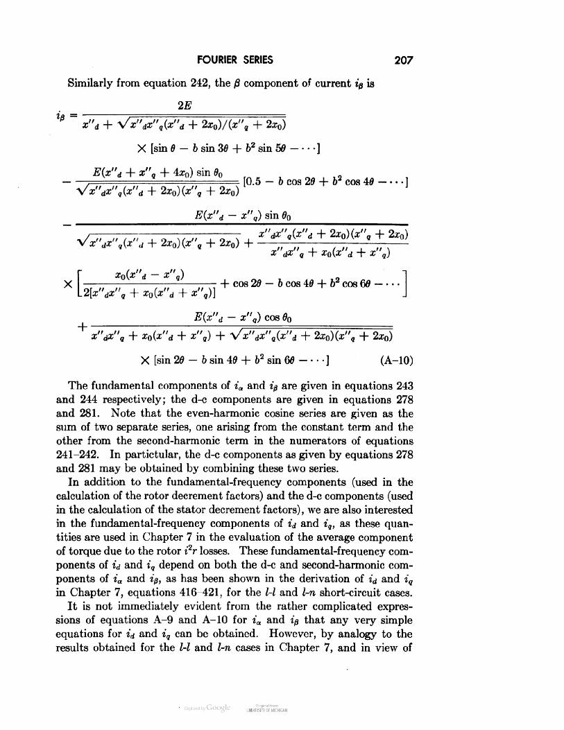
FOURIER SERIES 207Similarly from equation 242, the )3 component of current ip is2Ex"d + Vx"dx"q(x"d + 2x0)/(*"9 + 2x0)X [sin 0 - b sin 30 + b2 sin 50 ]E(x"d + x"q + 4x0) sin 00Vx"dx"q(x"d + 2x0)(x"q + 2x0)E(x"d - x"q) sin 60[0.5 - b cos 26 + b2 cos 40 ]x"dx"q(x"d + 2x0)(z"9 + 2x0)T" ,T" -\- T (T" , 4- 'r'M* a«t/ q l^ ~Q v* a T^ •" qj[Xn(x"d — x" ) I h cos 20-6 cos 40 + b2 cos 602[x"dz", + x0(z"d + x",)] IE(x"d - x"q) cos 00x"dx"q + x0(x"d + x"q) + Vx"dx"q(x"d + 2x0)(z", + 2x0)X [sin 20-6 sin 40 + 62 sin 60 ] (A-10)The fundamental components of ia and ip are given in equations 243and 244 respectively; the d-c components are given in equations 278and 281. Note that the even-harmonic cosine series are given as thesum of two separate series, one arising from the constant term and theother from the second-harmonic term in the numerators of equations241-242. In partictular, the d-c components as given by equations 278and 281 may be obtained by combining these two series.In addition to the fundamental-frequency components (used in thecalculation of the rotor decrement factors) and the d-c components (usedin the calculation of the stator decrement factors), we are also interestedin the fundamental-frequency components of id and iq, as these quan-tities are used in Chapter 7 in the evaluation of the average componentof torque due to the rotor i2r losses. These fundamental-frequency com-ponents of id and iq depend on both the d-c and second-harmonic com-ponents of ia and ip, as has been shown in the derivation of id and iqin Chapter 7, equations 416-421, for the l-l and l-n short-circuit cases.It is not immediately evident from the rather complicated expres-sions of equations A-9 and A-10 for ia and ip that any very simpleequations for id and iq can be obtained. However, by analogy to theresults obtained for the l-l and l-n cases in Chapter 7, and in view of
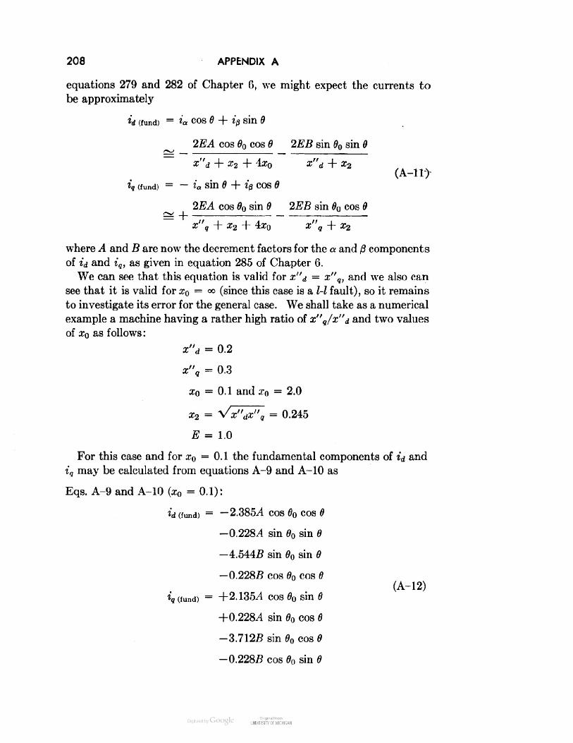
208 APPENDIX Aequations 279 and 282 of Chapter 6, we might expect the currents tobe approximatelyid (fund) = 4 cos 6 + ip sin 62EA cos 00 cos 6 2EB sin 00 sin 6x"d + x2 + 4x0 x"d + x2(iq (fund) = — ia Sin 6 + 10 COS 62EA cos 00 sin 0 2EB sin 00 cos 0= Hx2where 4 and B are now the decrement factors for the a and 0 componentsof id and iq, as given in equation 285 of Chapter 6.We can see that this equation is valid for x"d = x"q, and we also cansee that it is valid for x0 = °° (since this case is a l-l fault), so it remainsto investigate its error for the general case. We shall take as a numericalexample a machine having a rather high ratio of x"q/x"d and two valuesof xQ as follows:x"d = 0.2x"q = 0.3x0 = 0. 1 and x0 = 2.0
For this case and for x0 = 0. 1 the fundamental components of id andiq may be calculated from equations A-9 and A-10 asEqs. A-9 and A-10 (XQ = 0.1):id (fund) = —2.3854 cos 00 cos 0—0.228.4 sin 00 sin 0— 4.544.B sin 00 sin 0-0.2285 cos 00 cos 0(A-12)iq (fund) = +2.135A cos 00 sin 0+0.2284 sin 00 cos 0-3.712S sin 00 cos 6-0.2285 cos 00 sin 0

FUNDAMENTAL-FREQUENCY COMPONENTS OF /,, AND i, 209where the two armature decrement factors A and B have been intro-duced, as remarked beneath equation A-lI.For the same case, the symmetrical-component equation A-l 1 givesEq. A-11 fa = 0.1):^d(fund) = — 2.3664 COS 60 COS 6—4.494.B sin 60 sin 6(A-13)^(fund) = +2.1164 cos 6n sin 6-3.6705 sin 00 cos 6If the decrement factors A and B are assumed to be somewhat alike,we may compare the magnitudes of the currents found by the twomethods in the following table:00 = 90° 60 = 0°Eq. id iq id iqA-9andA-10 4.772 3.484 2.613 1.907A-11 4.494 3.670 2.366 2.116The approximate values of id are too small; the approximate valuesof iq are too large. In other words, the approximate formula does notshow quite enough effect of the subtransient saliency. On the otherhand, the differences are not great in view of the fact that in generalthe torques corresponding to these currents cannot usually be computedprecisely anyway, as the effective rotor resistances may not be knownvery accurately.If as an extreme case, we use x"d instead of x2 in the equation for id,and x"q instead of x2 in the equation for iq, so that x2 does not appearin the final equations at all, we find60 = 90° 0n = 0°id iq id iq5.00 3.333 2.50 2.00Now at 90° things are as we should naturally expect them to be: theapproximate value of id is too large and the approximate value of iqis too small, so that the effect of saliency is accentuated. On the otherhand, it is rather surprising to note that, for 60 = 0°, the approximatevalue of id is still too small and the approximate value of iq is still toolarge.

210 APPENDIX ANow we consider the case of x0 = 2.0 and find from the "exact"equations A-9 and A-10 the fundamental components of id and iq asFrom eqs. A-9 and A-10 (x0 = 2.0):id (fund) = —0.2374 COS 60 COS 6-0.0244 sin 00 sin 6-4.5005 sin 00 sin 6-0.0245 cos 60 cos 0(A-14)iq (fund) = +0.2344 cos 00 sin 6+0.0244 sin 00 cos 0—3.6745 sin 00 cos 0-0.0245 cos 00 sin 0The approximate equation A-ll givesEq. A-11 (x0 = 2.0):id (fund) = —0.2374 COS 00 COS 0-4.4945 sin 00 sin 0(A-15)iq (fund) = +0.2344 cos 00 sin 0-3.6705 sin 00 cos 0Similarly the "extreme" equation similar to equation A-ll but withz2 replaced by x"d (for id), and by x"q (for iq), givesid (fund) = —0.2384 cos 00 cos 0-5.0005 sin 00 sin 0(A-16)iq (fund) = +0.2334 cos 00 sin 0-3.3335 sin 00 cos 0Summarizing these results as before, we find00 =90°So == 0°Eq.id*9idt.A-9 and A-104.5243.6500.2610.211A-114.4943.6700.2370.234"Extreme"5.0003.3330.2380.233

FUNDAMENTAL-FREQUENCY COMPONENTS OF id AND i, 211Now with x0 = 2.0 the 60 = 90° case is seen to be by far the most im-portant as far as the armature d-c components are concerned. (00 = 90°was also the most important for the previous case of XQ = 0.1.) In thiscase the approximate equation A-11 gives very good results, whereasthe so-called "extreme" equation is not nearly so close. We note furtherthat the approximate equation does not depend on x0 when 00 = 90°,and indeed is the same as for a l-l fault.On the whole, we may conclude that the approximate equation A-llshould generally be satisfactory for the purpose of computing the rotori2r loss torque, as the errors are not great even for the rather extremecases considered here.

APPENDIX BTorqueThe component of force in any direction acting between any twogroups of current-carrying coils is equal to the rate of change, withrespect to displacement in that direction, of the total stored electromag-netic energy of the system.26 Similarly the torque acting on the rotorof an electric machine is equal to the rate of change, with respect toangle, of the total stored magnetic energy in the machine.For a synchronous machine the total stored electromagnetic energy Emay be written as (see Chapter 2, equations 5-8)E = \\Xaal1 a + Xbbi2b + Xcei2e + Xffdi2fd + Xlld^ld + Zll^'V H ---- ]+ Xabiaib + Xaciaic — Xafdiaifd —+ Xbcibic —lfdild +hdilq -\ ---- (B-l)The torque is therefore2dE 2 r 1I' . . 3 d . d 1— iaH — xab + iaic — Xac + 44 — XbcL do do d6 J, . I d . d d+ *o ifd — Xafd + iid — Xaid + liq — Xalq +'L do d6 do[". d d d+ ib ifd — Xbfd + iid — Xbid + iiq — Xbiq H ----L do do do JI d d d II+ ic ifd — xcfd + iid — Xdd + iiq — xclq -\ ---- (B-2)L op OP d6 j I212

TORQUE 213All other terms are zero, since the other inductances are not functionsof the rotor angle. The factor % has been introduced (as in equation 50of Chapter 2) in order to make the per unit torque unity for load cor-responding to rated volt-amperes.Now, from the definitions given in Chapter 2, equations 9-16, therates of change of the inductances with respect to rotor angle are3— Xaa= — 2xaa2 SU1 20363— xbb = —2xaa2 sin 206 = — 2xaa2 sin (26 + 120)363— xcc = -2xaa2 sin 26c = -2xaa2 sin (26 - 120)363— xab = +2xaa2 sin (26 + 60) = -2xaa2 sin (26 - 120)363— xbc = +2x„a2sin (26 — 180) = - 2xaa2 sin 20363— xca = +2xaa2 sin (20 - 60) = -2xaa2 sin (20 + 120)363— Xafd = -xafdsm6363— Xbfd = — Xa/dsin (0 — 120)363— Xcfd= -xafd sin (0 + 120)363— Xald= — Xaid sin 0363— Xbld= -Xaidsin (0 - 120)363— Xcld= -xaidsin(0+ 120)363= —Xalq COS 036

214 APPENDIX B3— Xbiq = — Xaiq cos (6 — 120)363— Xc'q = -Xalq COS (6 + 120)66etc. (B-3)Substituting these relations B-3 into the torque equation B-2, wefindT = %xaa2[i2a sin 20 + i2b sin (26 + 120) + i2c sin (26 - 120)]+ ixaa2[iaib sin (26 - 120) + ibic sin 26 + icia sin (26 + 120)]— s[xafdifd + Xaidiu + • • •] X[t'a sin 0 + ib sin (e - 120) + ic sin (0 + 120)]- I[XalqHq H ][4 cos e + fb cos (0 - 120) + ic cos (5 + 120)](B-4)This expression may be considerably simplified by noting thatidiq = -f { \[i2a sin 26 + t26 sin (26 + 120) + i2c sin (20 - 120)]+ iaib sin (25 - 120) + ibic sin 20 + icia sin (20 + 120)} (B-5)and that id and iq are obviously contained in the last two terms of equa-tion B—4. Moreover we may also note that, by equations 25 and 26of Chapter 2:Xaa2 = \(Xd~ Xq) (B-6)Substituting equations B-5, B-6, and 20 in equation B-4, we obtainT = ~(Xd— Xq)idiq + [Xafdtfd + Xal({ild H Vq — [Xalqilq + ' " ']*d(B-7)or, by equations 24:T = i,,fc - i,^, (62)which checks the result obtained in Chapter 2 from another point ofview.It has been shown in Chapter 7 that the torque may also be obtainedfrom two-phase armature (a, 0) quantities referred to axes fixed in thestator, asT = i&a - ia+f> (375)which may be derived directly from equation 62 by means of the sub-stitutions 217 and 374.

TORQUE 215It is of interest to note further that a similar expression for torquein terms of armature quantities may also be obtained directly in termsof the armature phase quantities. This may be simply accomplishedby substituting equations 169, together with the similar expressions forcurrent, in 375 above, whence the torque isT = -— [iattc ~ tb) + ibtta ~ tc) + icttb - *a)] (B-8)o'X/oorT = —= [*.(i6 - i«) + tb(ic - ia) + tctt. - »6)] (B-9)As noted above, the factor % appears in these expressions in order tomake the per-unit torque unity for unit currents and flux linkages.

REFERENCES1. S. B. CraRYand W. E. Duncan, "Amortisseur Windings for Hydrogenerators,"Electrical World, Vol. 115, June 28, 1941, pp. 2204-2206.2. R. E. Doherty and C. A. Nickle, "Synchronous Machines—I, an Extensionof Blondel's Two-Reaction Theory," AIEE Transactions, Vol. 45, 1926, pp. 912-926.3. R. H. Park, "Two-Reaction Theory of Synchronous Machines—GeneralizedMethod of Analysis—Part I," AIEE Transactions, Vol. 48, 1929, pp. 716-727.4. M. L. Waring and S. B. Crary, "Operational Impedances of a SynchronousMachine," General Electric Review, November 1932, pp. 578-582.5. C. Concordia, "Relations among Transformations Used in Electrical Engineer-ing Problems," General Electric Review, July 1938, pp. 323-325.6. A. W. Rankin, "The Equations of an Idealized Synchronous Machine," GeneralElectric Review, June 1944, pp. 31-36.7. A. W. Rankin, "Per-Unit Impedances of Synchronous Machines," AIEE Trans-actions, Vol. 64, 1945, Part I, pp. 569-573; Part II, pp. 839-841.'8. A. W. Rankin, "The Direct- and Quadrature-Axis Equivalent Circuits of theSynchronous Machine," AIEE Transactions, Vol. 64, 1945, pp. 861-868.9. A. W. Rankin, "Asynchronous and Single-Phase Operation of Synchronous/ Machines," AIEE Transactions, Vol. 65, 1946, pp. 1092-1102.S/ 10. R. E. Doherty, "A Simplified Method of Analyzing Short-Circuit Problems,"AIEE Transactions, Vol. 42, 1923, pp. 841-848.11. C. Concordia, "Rotating Electrical Machine Time Constants at Low Speeds,"AIEE Transactions, Vol. 65, 1946, pp. 882-887.12. AIEE Test Code for Synchronous Machines, No. 503, June 1945.V' 13. F. Von Roeschlaub, "Effect of Sequential Switching on Short-Circuit Currentsin Synchronous Machines," General Electric Review, June 1940, pp. 256-261.14. W. W. Kuyper, "Analysis of Short-Circuit Oscillograms," AIEE Transactions,Vol. 60, 1941, pp. 151-153.15. C. Concordia and F. J. Maginniss, "Inherent Errors in the Determination ofSynchronous-Machine Reactances by Test," AIEE Transactions, Vol. 64, 1945,pp. 288-294.16. H. C. Stanley, "An Analysis of the Induction Machine," AIEE Transactions,Vol. 57, 1938, pp. 751-757.V 17. R. E. Doherty and C. A. Nickle, "Synchronous Machines—IV, Single-PhaseShort Circuits," AIEE Transactions, Vol. 47, 1928, pp. 457-487.18. Edith Clarke, C. Concordia, and C. N. Weygandt, "Overvoltages Causedby Unbalanced Short Circuits (Effect of Amortisseur Windings)," AIEE Trans-actions, Vol. 57, 1938, pp. 453-468.,_ 19. J. B. Smith and C. N. Weygandt, "Double-Line-to-Neutral Short Circuit of anAlternator," AIEE Transactions, Vol. 56, 1937, pp. 1149-1155.216

BIBLIOGRAPHY 21720. Edith Clakke, Circuit Analysis of A-C Power Systems, Vol. I—Symmetricaland Related Components, John Wiley & Sons, 1943.21. C. A. Nickle, C. A. Pierce, and M. L. Henderson, "Single-Phase Short-Circuit Torque of a Synchronous Machine," AIEE Transactions, Vol. 51, 1932,pp. 966-971.22. Gabriel Kron, "Equivalent Circuit of the Salient-Pole Synchronous Machine,"General Electric Review, Vol. 44, 1941, pp. 679-683.23. A. H. Lauder, "Salient Pole Motors out of Synchronism," AIEE Transactions,Vol. 55, 1936, pp. 636-649.24. H. C. Anderson, Jr., "Voltage Variation of Suddenly Loaded Generators,"General Electric Review, August 1945, pp. 25-33.25. W. C. Johnson, Jr., "Starting Induction-Type Motors from Systems of LimitedCapacity," General Electric Review, December 1930, pp. 712-722.26. J. C. Maxwell, Electricity and Magnetism, Vol. II, Chapters VI and VII, Ox-ford University Press, 1892.BibliographyThis bibliography is by no means complete, as it contains merely some of thearticles that the author has found to be of interest. On the other hand, it is notconfined to the scope of the present volume. Instead, it contains treatments ofmany other topics, including background material, determination of machine param-eters, additional applications of the theory developed here, and some of the morerecent extensions of the theory. Papers already listed among the references are notincluded.1. A. Blondel, Synchronous Motors and Converters, Part 3, Chapter I, McGraw-Hill Book Company, 1913.2. Ft. E. Doherty and O. E. Shirley, "Reactance of Synchronous Machines andIts Applications," AIEE Transactions, Vol. 37, Part 2, 1918, pp. 1209-1297.3. A. Blondel, "The Two-Reaction Method for Study of Oscillatory Phenomenain Coupled Alternators," Revue ginirale de I'electricity, Vol. 13, February, March,1923, pp. 235-251, 515-531.4. F. Kade, "Influence of the Damping Torque Winding on Short-Circuit Syn-chronous Machines," Archiv fur Elektrotechnik, Vol. 12, June 1923, pp. 345-359.5. R. E. Doherty and C. A. Nickle, "Synchronous Machines II—Steady-StatePower-Angle Characteristics," AIEE Transactions, Vol. 45, 1926, pp. 927-942.6. R. E. Doherty and C. A. Nickle, "Synchronous Machines III—Torque-AngleCharacteristics under Transient Conditions," AIEE Transactions, Vol. 46, 1927,pp. 1-18.7. A. R. Stevenson and R. H. Park, "Graphical Determination of MagneticFields," AIEE Transactions, Vol. 46, 1927, pp. 112-136.8. R. W. Wieseman, "Graphical Determination of Magnetic Fields; Practical Ap-plication to Salient-Pole Synchronous-Machine Design," AIEE Transactions,Vol. 46, 1927, pp. 141-154.9. P. L. Alger, "The Calculation of the Armature Reactance of SynchronousMachines," AIEE Transactions, Vol. 47, 1928, pp. 493-512.10. A. Mandl, "Single-Phase Short Circuits of Three-Phase Generators," Archivfur Elektrotechnik, Vol. 19, March 1928, pp. 485-513.11. R. H. Park and B. L. Robertson, "The Reactances of Synchronous Machines,"AIEE Transactions, Vol. 47, April 1928, pp. 514-535.

218 REFERENCES12. R. H. Park, "Definition of an Ideal Synchronous Machine and Formula for theArmature Flux Linkages," General Electric Review, Vol. 31, June 1928, pp. 332-334.13. T. M. Linville, "Starting Performance of Salient-Pole Synchronous Motors,"AIEE Journal, Vol. 49, February 1930, pp. 145-147.14. Gabriel Kron, "Generalized Theory of Electrical Machinery," AIEE Trans-actions, Vol. 49, April 1930, pp. 666-685.15. R. E. Dohertt and C. A. Nickle, "Synchronous Machines V—Three-PhaseShort Circuits," AIEE Transactions, Vol. 49, 1930, pp. 700-714.16. Y. Ikeda and M. Mori, "Single-Phase Short Circuit of Synchronous Machine,"Zeitschrift fur angewandte Mathematik und Mechanik, Vol. 11, August 1931,pp. 274-284.17. S. H. Wright, "Determination of Synchronous-Machine Constants by Test,"AIEE Transactions, Vol. 50, December 1931, pp. 1331-1350; AIEE Journal,Vol. 50, December 1931, p. 961.18. B. L. Robertson, "Synchronous-Machine Reactance Measurements," GeneralElectric Review, Vol. 35, February 1932, pp. 126-130.19. F. A. Hamilton, Jr., "Field Tests to Determine Damping Characteristics ofSynchronous Generators," AIEE Transactions, Vol. 51, September 1932, pp. 775-779; General Electric Review, Vol. 35, July 1932, pp. 384-388.20. S. B. Crary and M. L. Waring, "Torque-Angle Characteristics of SynchronousMachines following System Disturbances," AIEE Transactions, Vol. 51, Sep-tember 1932, pp. 764-773.21. L. P. Shildneck, "Synchronous-Machine Reactances, a Fundamental andPhysical Viewpoint," General Electric Review, Vol. 35, November 1932, pp. 560-565.22. R. H. Park, "Two-Reaction Theory of Synchronous Machines—II," AIEETransactions, Vol. 52, 1933, pp. 352-355.23. W. M. Hanna, "Uses of Synchronous-Machine Quantities in System Studies,"General Electric Review, Vol. 36, March 1933, pp. 116-128.24. S. B. Crary, L. P. Shildneck, and L. A. March, "Equivalent Reactance ofSynchronous Machines," AIEE Transactions, Vol. 53, January 1934, pp. 124-132.25. S. B. Crary, A. H. Lauder, and D. R. Shoults, "Pull-In Characteristics ofSynchronous Motors," AIEE Transactions, Vol. 54, 1935, pp. 1385-1395.26. Gabriel Kron, "The Application of Tensors to the Analysis of Rotating Elec-trical Machinery," General Electric Review, a serial, April 1935 to December 1937(Reprinted in book form, 1938).27. P. S. Shdanov, "Asynchronous Behavior of Electrical Systems," Elek., November1936, No. 21, pp. 17-26.28. A. Berger, "Synchronous Machinery," Leningrad, ONTI, 1936 (book).29. S. B. Crary, "Two-Reaction Theory of Synchronous Machines," Electrical En-gineering, Vol. 56, January 1937, pp. 27-31 and p. 36.30. C. Concordia and H. Poritsky, "Synchronous Machine with Solid CylindricalRotor," Electrical Engineering, Vol. 56, January 1937, pp. 49-58 and p. 179.31. J. W. Butler and C. Concordia, "Analysis of Series Capacitor ApplicationProblems," AIEE Transactions, Vol. 56, 1937, pp. 975-988.32. C. Concordia, "Two-Reaction Theory of Synchronous Machines with AnyBalanced Terminal Impedance," Electrical Engineering, Vol. 56, September 1937,pp. 1124-1127.

BIBLIOGRAPHY 21933. J. Fallou, "Asynchronous Behavior and Spontaneous Resumption of Synchron-ism in Interconnected Systems," Revue genirale de Velectricite, Vol. 41, No. 15,April 10, 1937, pp. 451-465.^^34. A. R. Miller and W. S. Weil, Jr., "Alternator Short-Circuit Currents underUnsymmetrical Terminal Conditions," AIEE Transactions, Vol. 57, October1937, pp. 1268-1276.35. A. R. Miller and W. S. Weil, Jr., "Operational Solution of A-C Machines,"Electrical Engineering, Vol. 55, November 1937, pp. 1191-1200.36. B. R. Prentice, "Fundamental Concepts of Synchronous-Machine Reactances,"AIEE Transactions (Supplement), Vol. 56, 1937, pp. 1-21.37. Edith Clarke, C. N. Weygandt, and C. Concordia, "Overvoltages Causedby Unbalanced Short Circuits—Effect of Amortisseur Windings," AIEE Trans-actions, Vol. 57, August 1938, pp. 453-466.38. C. Concordia, S. B. Crary, and J. M. Lyons, "Stability Characteristics ofTurbine Generators," AIEE Transactions, Vol. 57, 1938, pp. 732-744.39. E. C. Whitney and H. E. Criner, "Determination of Short-Circuit Torquesin Turbine Generators by Test," AIEE Transactions, Vol. 59, 1940, pp. 885-889.40. M. M. Liwschitz, "Positive and Negative Damping in Synchronous Machines,"AIEE Transactions, Vol. 60, 1941, pp. 210-213.41. C. Concordia and G. K. Carter, "Negative Damping of Electrical Machinery,"AIEE Transactions, Vol. 60, 1941, pp. 116-118.42. C Concordia, S. B. Crary, and Gabriel Kron, "The Doubly Fed Machine,"AIEE Transactions, Vol. 61, 1942, pp. 286-289.43. Gabriel Kron, "Equivalent Circuits for the Hunting of Electrical Machinery,"AIEE Transactions, Vol. 61, 1942, pp. 290-296.44. Gabriel Kron, A Short Course in Tensor Analysis for Electrical Engineers,John Wiley & Sons, 1942.45. C. Concordia, "Steady-State Stability of Synchronous Machines as Affectedby Voltage Regulator Characteristics," AIEE Transactions, Vol. 63, 1944,pp. 215-220.46. C. Concordia, S. B. Crary, C. E. Kilbourne, and C. N. Weygandt, Jr.,"Synchronous Starting of Generator and Motor," AIEE Transactions, Vol. 64,1945, pp. 629-634.47. Gabriel Kron and C. Concordia, "Damping and Synchronizing Torques ofPower Selsyns," AIEE Transactions, Vol. 64, 1945, pp. 366-371.48. C. Concordia and M. Temoshok, "Resynchronizing of Generators," AIEETransactions, Vol. 66, 1947, pp. 1512-1518.49. Gabriel Kron, "Steady-State Equivalent Circuits of Synchronous and Induc-tion Machines," AIEE Transactions, Vol. 67, 1948, pp. 175-181.50. C. Concordia, "Synchronous-Machine Damping and Synchronizing Torques,"AIEE technical paper 51-122, AIEE Transactions, Vol. 70, 1951.

_EMPTY_

INDEXAir-gap flux, 12a, 0, 0 components, 77, 78armature voltage equations, 80Amortisseur, 4, 6Amortisseur bars, 6Armature inductance, 10Armature transients, neglect of, 68, 186Armature voltage equations, o, b, c, 8d, q, 0, 17a, /3, 0, 80Asynchronous operation, 165Axes, direct and quadrature, 6Ceiling, exciter, 195Components, a, 0, 0, 77, 78d, q, 0, 14-17/, b, 0, 1661, 2, 0 (symmetrical), 103Constant flux linkage, 34, 57, 76Current-density wave, 29Damper winding, 4Decrement factors, double-line-to-ground fault, 108short-circuit torque, 142single-phase faults, 90three-phase fault, 63Degrees, electrical, 1Direct axis, 6amortisseur, 9subtransient reactance, 57synchronous reactance, 16tests for, 23, 24transient reactance, 35Double-line-to-ground fault, 100current, a, 0, 1016, c, 111open-phase voltage, 113torque, 143, 161Electrical degrees, 1Energy, stored electromagnetic, 212Equivalent static circuit, 19, 126, 171Exciter ceiling, 195Exciter response, 197Faults, see Short circuitField current, double-line-to-ground shortcircuit, 112in terms of armature voltage, 24on application of load, 201single-phase short circuit, 95three-phase short circuit, 72Field excitation, change of, 191effect on starting torque, 180in terms of armature voltage, 24Field flux linkage, 9constant, 34in terms of armature voltage, 35Flux, air gap, 12Flux-density wave, 29Flux linkage, 9, 10constant, 34, 57, 76field, 34trapped, 60Flux-linkage factors, 135for l-l fault, 136-138Flux linkages as a function of armaturecurrent, in terms of id, iq, io, 18in terms of symmetrical components,150Forward- and backward-rotating quanti-ties, 166Fourier series, 205Harmonic components, l-l fault, current,85, 94flux linkage, 86open-phase voltage, 87torque, 139l-n fault, current, 86, 94torque, 146ll-n fault, current, 206Impedance, operational, 18, 56standstill, 125221

222INDEXInductance, armature, 10rotor, 12Inductance relations, 10Infinite bus, 26Leakage reactance, 3Line-to-ground fault, 81current, 86open-phase voltages, 83torque, 143, 160Line-to-line fault, current, 76open-phase voltage, 87torque, 139, 160Maximum power, 40Mmf, rotor, 91Negative-phase-sequence reactance, 87,89Reactance, leakage, 3negative-phase sequence, 87, 89, 102,107subtransient, direct axis, 57quadrature axis, 57synchronous, direct axis, 16quadrature axis, 16transient, direct axis, 35zero-phase sequence, 16Reactive volt-amperes, 44versus angle, 45Reciprocity of mutual inductances, 19Reluctance torque, 30Response of exciter, 197Rotor-circuit currents with three-phasefaults, 55Rotor circuits, 6Rotor inductances, 12Rotor mmf's, 91Saliency, 6effect on steady-state torque, 39subtransient, 58transient, 189Saturation, 196Sequential faults, 114Short circuit, decrement factors for, 90,142for double-line-to-ground fault, 102,107Open-phase voltage, for double-line-to-ground faults, 113for line-to-line faults, 87Operational impedances, 18, 56Permeance, 11Per-unit quantities, 20Per-unit time, 22Power, input, 27limit, 40maximum, 40output, 25, 36Power-angle characteristics, 27, 37for two machines, 46-48with constant flux linkages, 38Problems, for Chapter 2, 31for Chapter 3, 52for Chapter 4, 75for Chapter 5, 98for Chapter 6, 118for Chapter 7, 164for Chapter 8, 184for Chapter 9, 203Quadrature axis, 6amortisseur, 9subtransient reactance, 57synchronous reactance, 16double line to ground, 100field current, 72, 95line to line, 76line to neutral, 81sequential, 114test for Xd, 24three phase, 54from load, 58oscillograms, 66steady-state current, 59transient current, 65with armature resistance, 67time constants, 63, 142torques, 119Short-circuit current, double line toground, 111, 112fundamental-frequency components ofid, iq, 157line to ground, 94line to line, 94three phase, 58, 66, 71Sinusoidally distributed winding, 7
INDEX223Slip, 165Slip test for synchronous reactance, 23Slots, stator, 8Speed change, 130Stability, 40Starting torque, 165see also TorqueSteady-state performance, 32, 165Steady-state short-circuit current, 59Subtransient reactances, 57Subtransient time constant for three-phase fault, 62Symmetric-rotor machine, 151Symmetrical components, 103mathematical definition, 104of torque, 149physical meaning, 103, 106relation to a, /3, 0 components, 105short-circuit currents, 152Synchronism, 3Synchronizing, 58Synchronous reactance, direct and quad-rature axis, 16short-circuit test for, 24slip test for, 23Tests, for synchronous reactance, 24short circuit, 66Three-phase short circuit, current, 66field current, 72torque, 145, 161with armature resistance, 67Time constant, field load, 69, 188field open circuit, 64rotor open circuit, 64rotor short circuit, 124short circuit, 142-144double line to ground, armature, 110rotor, 108line to line, armature, 90rotor, 93line to neutral, armature, 90rotor, 95three phase, 60, 63, 64Torque, derivation of equations for, 28,212harmonic components, of l-l, 139of l-n, 146in terms of complex quantities, 148in terms of ia, i&, ic, 215Torque, in terms of id, iq, 28in terms of ia, ip, 147in terms of symmetrical components,149-152reluctance, 30short circuit, 119approximate equations for, 160examples of, 162general formulas for, 142line to line, 134examples of, 140-141three phase, 119components of, 127effect of rotor resistance, 123effect of stator resistance, 121maximum unidirectional, 122, 133neglecting resistance, 120unidirectional, 147starting, 165approximate equation for, 160at half speed, 174average, 170, 177comparison of exact and approxi-mate, 175equivalent circuit for, 171in terms of id, iq, 177oscillating component of, 171, 183with field excitation, 180Transformation equations, to d, q, 0 axes,17current, 14flux linkage, 15voltage, 16Transformations, a, /3, 0 axes, 77d, q, 0 axes, 14-17/, b, 0 axes, 1661,2,0 (symmetrical components) axes,104Transients, neglect of armature, 68,186Trapped flux, 60Turn ratio, 21Vector diagram, 32construction, 33with resistance load, 70Voltage, armature, 8, 17back of transient reactance, 35open phase, for l-l fault, 84for ll-n fault, 113

224 INDEXVoltage dip, 185estimating chart, 199field-current change, 201initial, 189minimum voltage, 193with initial load, 200Voltage equations, armature, 8, 17, 80Voltage regulator, 185, 191cVoltage rise on application of load, 189Volt-amperes, reactive, 44Winding, amortisseur (or damper), 4sinusoidally distributed, 7Zero-phase-sequence reactance, 16test for, 2515269 220 AA A 30

_EMPTY_

_EMPTY_

_EMPTY_

~«• aJUNIVERSITY OF MICHIGAN3 9015 00201 9779

,i

H ■I