Embed Size (px)
Citation preview
Synchronization in theNetwork-Integrated Multimedia Middleware (NMM)
Stephan Didas
Bachelor-Arbeit
nach einem Thema von
Prof. Dr.-Ing. Philipp Slusallek
Naturwissenschaftlich-Technische Fakultat I
Fachrichtung 6.2 – Informatik
Universitat des Saarlandes, Saarbrucken, 2004
SA
RA V I E N
SI
S
UN
I VE R S I T
AS
Hiermit erklare ich an Eides statt, dass ich die vorliegende Arbeit selbst ange-fertigt und nur die angegebenen Quellen und Hilfsmittel verwendet habe.
Saarbrucken, den
Disclaimer
The software described in this document is under continuous development.Some concepts and software components therefore may be different in thesoftware distributions available on the internet. For further informationabout the current state of the project and the software distribution see [1].
Contents
1 Introduction 3
1.1 Media classification . . . . . . . . . . . . . . . . . . . . . . . . . . 31.2 Introduction to synchronization . . . . . . . . . . . . . . . . . . . 41.3 Synchronization requirements . . . . . . . . . . . . . . . . . . . . 5
1.3.1 Hard and soft real-time constraints . . . . . . . . . . . . . 61.3.2 The special case of lip synchronization . . . . . . . . . . 6
2 Introduction to NMM 7
2.1 Nodes . . . . . . . . . . . . . . . . . . . . . . . . . . . . . . . . . 82.2 Messages . . . . . . . . . . . . . . . . . . . . . . . . . . . . . . . 9
3 Synchronization in NMM 11
3.1 Overview . . . . . . . . . . . . . . . . . . . . . . . . . . . . . . . 113.2 Elementary data types . . . . . . . . . . . . . . . . . . . . . . . . 13
3.2.1 Rational numbers . . . . . . . . . . . . . . . . . . . . . . . 133.2.2 Time representation - Time, Interval and UserTime . . 133.2.3 Time information in the multimedia stream - Timestamp 14
3.3 Objects in the graph . . . . . . . . . . . . . . . . . . . . . . . . . 153.3.1 Clock and TimedElement . . . . . . . . . . . . . . . . . . 153.3.2 Timestamp creation - StreamTimer . . . . . . . . . . . . 163.3.3 GenericSyncSinkNode and its subclasses . . . . . . . . . 163.3.4 Controller and its subclasses . . . . . . . . . . . . . . . 183.3.5 Synchronizer . . . . . . . . . . . . . . . . . . . . . . . . 21
3.4 Events related to synchronization . . . . . . . . . . . . . . . . . . 223.4.1 sync enable and sync disable . . . . . . . . . . . . . . 223.4.2 sync reset . . . . . . . . . . . . . . . . . . . . . . . . . . 23
4 Plug-ins and Applications 25
4.1 Source nodes . . . . . . . . . . . . . . . . . . . . . . . . . . . . . 254.1.1 Live sources . . . . . . . . . . . . . . . . . . . . . . . . . . 25
4.2 Filter nodes . . . . . . . . . . . . . . . . . . . . . . . . . . . . . . 264.3 Converter nodes . . . . . . . . . . . . . . . . . . . . . . . . . . . 264.4 Sink nodes . . . . . . . . . . . . . . . . . . . . . . . . . . . . . . . 27
4.4.1 Video sinks . . . . . . . . . . . . . . . . . . . . . . . . . . 274.4.2 Audio sinks . . . . . . . . . . . . . . . . . . . . . . . . . . 27
4.5 Audio visualization . . . . . . . . . . . . . . . . . . . . . . . . . 29
I
CONTENTS II
4.5.1 The mp3vis and mp3vis2 applications . . . . . . . . . . . 294.5.2 ScopeNode and SAnalyzerNode . . . . . . . . . . . . . . . 304.5.3 Synchronization in the application code . . . . . . . . . . 31
4.6 MPEG decoding . . . . . . . . . . . . . . . . . . . . . . . . . . . 31
A Source Files 34
Chapter 1
Introduction
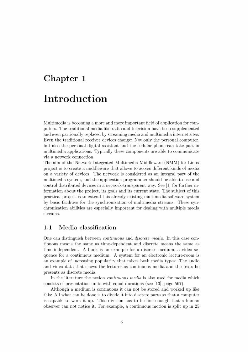
Multimedia is becoming a more and more important field of application for com-puters. The traditional media like radio and television have been supplementedand even partionally replaced by streaming media and multimedia internet sites.Even the traditional receiver devices change: Not only the personal computer,but also the personal digital assistant and the cellular phone can take part inmultimedia applications. Typically these components are able to communicatevia a network connection.The aim of the Network-Integrated Multimedia Middleware (NMM) for Linuxproject is to create a middleware that allows to access different kinds of mediaon a variety of devices. The network is considered as an integral part of themultimedia system, and the application programmer should be able to use andcontrol distributed devices in a network-transparent way. See [1] for further in-formation about the project, its goals and its current state. The subject of thispractical project is to extend this already existing multimedia software systemby basic facilities for the synchronization of multimedia streams. These syn-chronization abilities are especially important for dealing with multiple mediastreams.
1.1 Media classification
One can distinguish between continuous and discrete media. In this case con-tinuous means the same as time-dependent and discrete means the same astime-independent. A book is an example for a discrete medium, a video se-quence for a continuous medium. A system for an electronic lecture-room isan example of increasing popularity that mixes both media types: The audioand video data that shows the lecturer as continuous media and the texts hepresents as discrete media.
In the literature the notion continuous media is also used for media whichconsists of presentation units with equal durations (see [13], page 567).
Although a medium is continuous it can not be stored and worked up likethis: All what can be done is to divide it into discrete parts so that a computeris capable to work it up. This division has to be fine enough that a humanobserver can not notice it. For example, a continuous motion is split up in 25
3
CHAPTER 1. INTRODUCTION 4
or 30 video frames per second. The audio signal of a 1kHz sine wave is sampled44100 times per second, and only the value at the sample times is stored. Thatmeans even continuous media are stored as discrete values. A multimedia datastream is a sequence of such values which do not in any case provide usefulinformation for themselves. For example, one audio sample without the contextof other samples does not tell us anything about the song it is taken from. Tocharacterize a multimedia stream, it is necessary to divide it into sensible partswhich are called logical data units, or short LDU’s.
There is no unique way to divide a stream in LDU’s. Regard a stream ofraw audio data (Stereo, 16 bits per sample with a sample rate of 48000 kHz):One could say that each audio sample in the stream is an LDU. We have seenthat this does not make sense in most of the cases. Another possibility is togroup a reasonable number of samples, let us say 1024, together to one LDU.With the above parameters, 1024 samples are 4096 bytes. So this LDU wouldbe a unit that can be practically transported and worked up by a computer. Ifthe presentation consists of multiple songs, one can even regard a whole song asan LDU. In a video stream it can make sense simply to view each video frameas an LDU. However even in this case there could be other sensible possibilities:In an MPEG stream, several following video frames form a so-called group ofpictures or GOP. This GOP can also be seen as the LDU of the MPEG videostream.
So there are different levels of granularity how to regard media data. Itdepends on the application which point of view to choose.
1.2 Introduction to synchronization
Now we want to introduce some useful notions related to multimedia and syn-chronization. In the context of multimedia systems synchronization in generalrefers to the content, spatial and temporal relations between different mediaobjects. Like in most of the literature we will use the notion synchronizationwith the main focus on the temporal relations between the media objects.
The notion can be further specialized according to the regarded media ob-jects:
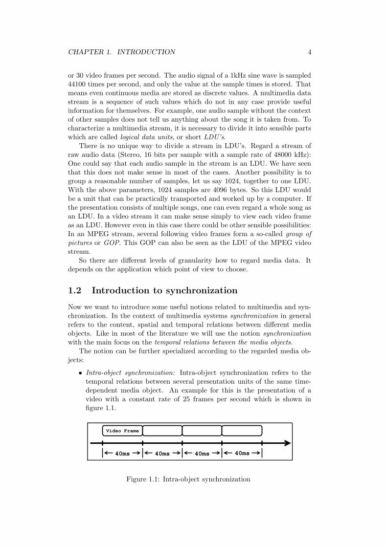
• Intra-object synchronization: Intra-object synchronization refers to thetemporal relations between several presentation units of the same time-dependent media object. An example for this is the presentation of avideo with a constant rate of 25 frames per second which is shown infigure 1.1.
40ms 40ms 40ms 40ms
Video Frame
Figure 1.1: Intra-object synchronization
CHAPTER 1. INTRODUCTION 5
Video
Audio Audio
Slide
Audio Audio
Video Video
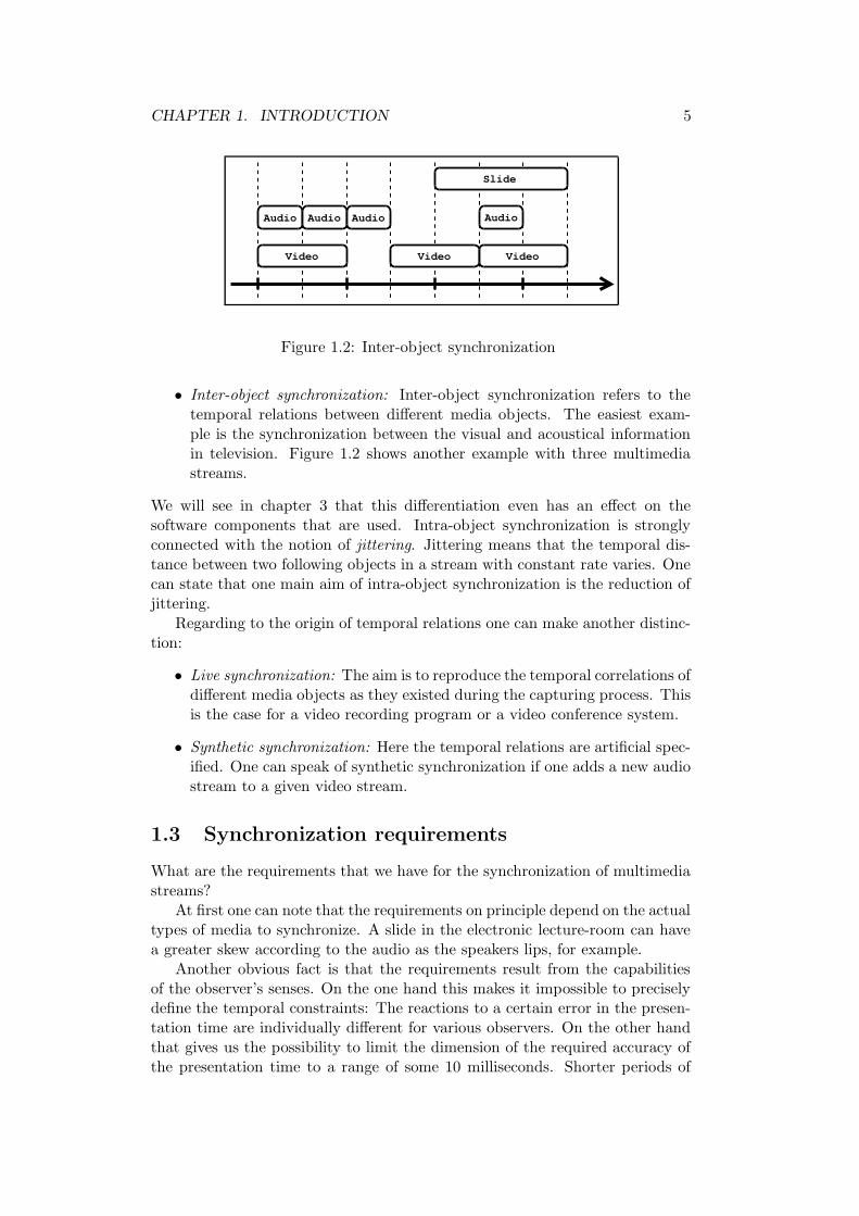
Figure 1.2: Inter-object synchronization
• Inter-object synchronization: Inter-object synchronization refers to thetemporal relations between different media objects. The easiest exam-ple is the synchronization between the visual and acoustical informationin television. Figure 1.2 shows another example with three multimediastreams.
We will see in chapter 3 that this differentiation even has an effect on thesoftware components that are used. Intra-object synchronization is stronglyconnected with the notion of jittering. Jittering means that the temporal dis-tance between two following objects in a stream with constant rate varies. Onecan state that one main aim of intra-object synchronization is the reduction ofjittering.
Regarding to the origin of temporal relations one can make another distinc-tion:
• Live synchronization: The aim is to reproduce the temporal correlations ofdifferent media objects as they existed during the capturing process. Thisis the case for a video recording program or a video conference system.
• Synthetic synchronization: Here the temporal relations are artificial spec-ified. One can speak of synthetic synchronization if one adds a new audiostream to a given video stream.
1.3 Synchronization requirements
What are the requirements that we have for the synchronization of multimediastreams?
At first one can note that the requirements on principle depend on the actualtypes of media to synchronize. A slide in the electronic lecture-room can havea greater skew according to the audio as the speakers lips, for example.
Another obvious fact is that the requirements result from the capabilitiesof the observer’s senses. On the one hand this makes it impossible to preciselydefine the temporal constraints: The reactions to a certain error in the presen-tation time are individually different for various observers. On the other handthat gives us the possibility to limit the dimension of the required accuracy ofthe presentation time to a range of some 10 milliseconds. Shorter periods of
CHAPTER 1. INTRODUCTION 6
time are normally not noticeable for a human observer. [12] and [13] give amore detailed description of synchronization requirements for different types ofmedia.
1.3.1 Hard and soft real-time constraints
Synchronization always deals with real-time constraints. From the operatingsystem’s point of view such real-time constraints can be divided into hard andsoft real-time constraints. The real-time constraints are called hard if it is nec-essary for the correct behaviour of the software or system that a given deadlineis kept. This can even lead to a danger for human’s life (one may think of indus-trial robots or airbag control). But what happens in a multimedia applicationif a deadline cannot be kept? We will see later that in several cases a delay ofthe presentation is not even noticeable to the observer. Therefore in the case ofmultimedia applications one can speak of soft real-time constraints. This makesit possible to avoid using special software like a real-time operating system (seealso [3]). At the moment the NMM project uses a standard Linux operatingsystem. That means the operating system does not support any guaranteedreaction times.
1.3.2 The special case of lip synchronization
Lip synchronization refers to a presentation of audio and video and the temporalrelations between them for the particular case of human speaking.
In this case it is also difficult to gain clear results: Even a test sequencewithout any skew between video and audio is declared as incorrect by sometest users (see [12] for more details.) Moreover there are many conditions thathave an influence on the recognition of synchronization errors that complicatea general statement. Regard an audio/video sequence that shows a humanspeaker: The brightness of the images and the distance to the speaker have aninfluence on the detection of synchronization errors.
Experiments have shown that in most cases it is sufficient to keep the skewbetween audio and video in a region between -80 milliseconds (audio behindvideo) and 80 milliseconds (audio ahead of video). Regard an example appli-cation that plays MPEG-encoded audio/video streams. This application hasto ensure that a single video frame is displayed at most 80 milliseconds beforeor after the intended presentation time. For further information please take alook at [12], pages 580 - 584, or [13], pages 588 - 592.
It is interesting that people are more tolerant against audio/video skews ifthe audio follows the video. As a result of the different velocities of sound andlight we make the experience of a slightly delayed acoustic impression everyday.
Chapter 2
Introduction to NMM
The Network-Integrated Multimedia Middleware (NMM) for Linux is being devel-oped for the last 2 years by the computer graphics group of Saarland University.Information about the project in general and its current state can be found onthe internet (see [1]). NMM is free software implemented in C++; the currentdistribution is available for download at the project’s homepage.
One main aim of NMM is to simplify implementing multimedia applicationsby providing easy access to different kinds of hardware and different multimediaformats.
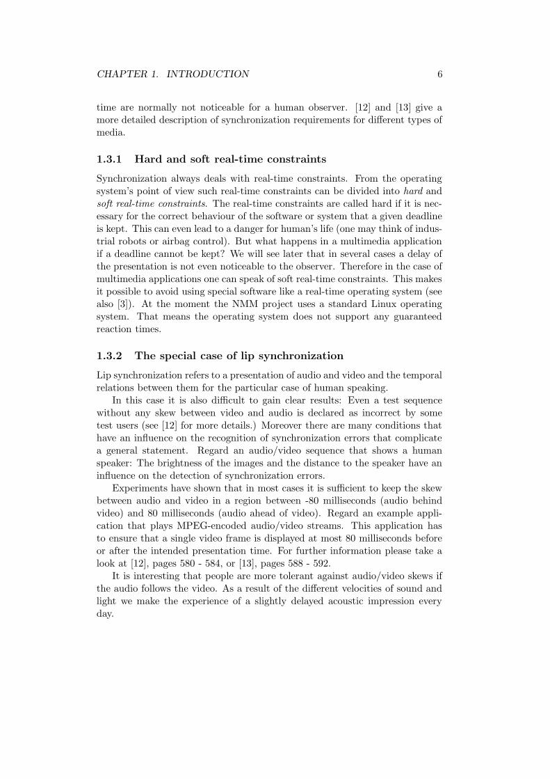
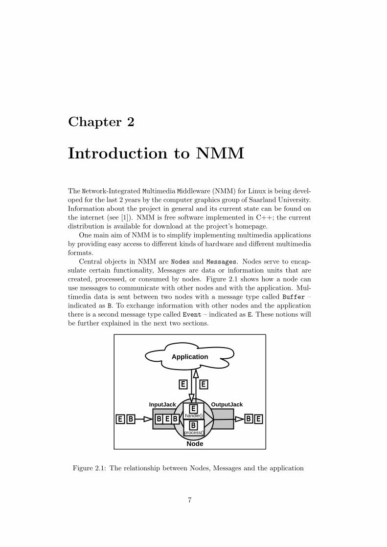
Central objects in NMM are Nodes and Messages. Nodes serve to encap-sulate certain functionality, Messages are data or information units that arecreated, processed, or consumed by nodes. Figure 2.1 shows how a node canuse messages to communicate with other nodes and with the application. Mul-timedia data is sent between two nodes with a message type called Buffer –indicated as B. To exchange information with other nodes and the applicationthere is a second message type called Event – indicated as E. These notions willbe further explained in the next two sections.
Node
Application
E BB
process()
B B
EE
InputJack OutputJack
BE E
Ehandle()
Figure 2.1: The relationship between Nodes, Messages and the application
7
CHAPTER 2. INTRODUCTION TO NMM 8
2.1 Nodes
On the one hand a node can provide an interface to a concrete hardware devicelike a soundcard or a camera. On the other hand it can also be a softwareobject like a video colorspace converter or an audio filter.
To realize connections with each other nodes have so-called Input- andOutputJacks. One could compare the nodes to things like a guitar, an amplifieror effects and the Jacks to the real jacks that connect them.
In principle there is no restriction on the number of input and output jacks.Not every node must have both Input- and OutputJacks. One may think ofa file reader node as a data producer (source node) that does not need anInputJack or a video display sink node without an OutputJack a a pure dataconsumer. Multiple OutputJacks (demultiplexer node with one input only) ormultiple InputJacks (multiplexer node with one output only) are allowed. Theabove types together with filter node and converter node make the six typesof nodes that are distingiushed. There are so-called Formats to describe thedata content of a multimedia stream. A filter node usually has the same inputand output data format. An example is a node that adds an effect to an audiostream. A converter node explicitly changes the format of incoming data. Onemay think of a node that decodes compressed MPEG video data into singlevideo frames.
There is a group of classes that represents the different generic node types:GenericSourceNode, GenericProcessorNode, GenericMultiplexerNode, Ge-nericDemultiplexerNode, GenericConverterNode, GenericFilterNode andGenericSinkNode. They simplify the programming of new nodes, so that aprogrammer only needs to implement the functionality of the new node. Forexample, the GenericSourceNode has a member function with the type
Buffer* produceBuffer()
and the GenericProcessorNode has a function called
Buffer* processBuffer(Buffer*)
which serves to encapsulate the functionality of the nodes1. A Buffer is acontainer for multimedia data. This will be further explained in section 2.2.
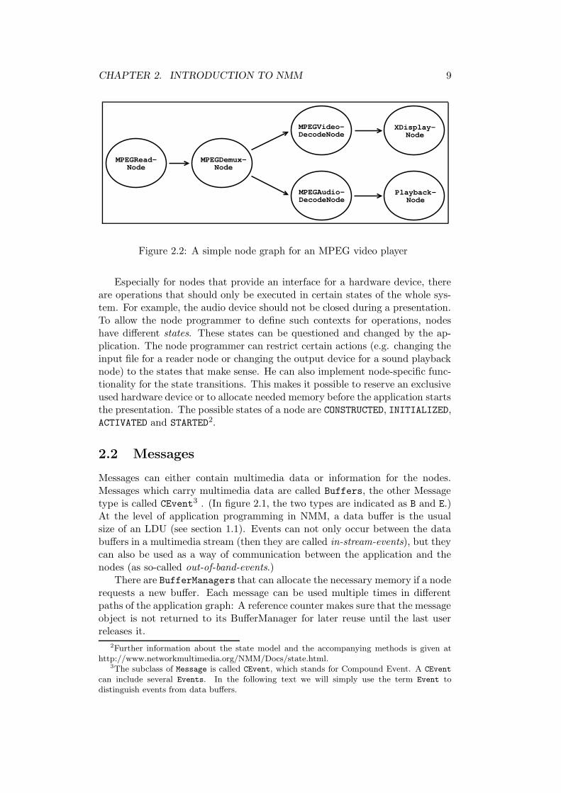
With their jack connections nodes are able to form general flow graph struc-tures. Figure 2.2 shows an example graph for a simple MPEG video player. Itconsists of six nodes: The only source in the graph is an MPEGReadNode thatreads the MPEG-encoded data from the hard disc. Then the data is split upinto the audio and video components by the MPEGDemuxNode. The MPEGVi-
deoDecodeNode converts the MPEG video stream into a raw video stream, thesame is done by the MPEGAudioDecodeNode for the audio stream. The XDis-
playNode and the PlaybackNode finally present the video and audio data tothe user.
One path in such a flow graph describes a path of data or information flowin the graph; the messages that flow along such a path are called a stream.
1For more information about the node types and a list of currently available nodes seehttp://www.networkmultimedia.org/NMM/Status/Plugins/index.html.
CHAPTER 2. INTRODUCTION TO NMM 9
MPEGRead-Node
MPEGDemux-Node
XDisplay-Node
Playback-Node
MPEGVideo-DecodeNode
MPEGAudio-DecodeNode
Figure 2.2: A simple node graph for an MPEG video player
Especially for nodes that provide an interface for a hardware device, thereare operations that should only be executed in certain states of the whole sys-tem. For example, the audio device should not be closed during a presentation.To allow the node programmer to define such contexts for operations, nodeshave different states. These states can be questioned and changed by the ap-plication. The node programmer can restrict certain actions (e.g. changing theinput file for a reader node or changing the output device for a sound playbacknode) to the states that make sense. He can also implement node-specific func-tionality for the state transitions. This makes it possible to reserve an exclusiveused hardware device or to allocate needed memory before the application startsthe presentation. The possible states of a node are CONSTRUCTED, INITIALIZED,ACTIVATED and STARTED2.
2.2 Messages
Messages can either contain multimedia data or information for the nodes.Messages which carry multimedia data are called Buffers, the other Messagetype is called CEvent3 . (In figure 2.1, the two types are indicated as B and E.)At the level of application programming in NMM, a data buffer is the usualsize of an LDU (see section 1.1). Events can not only occur between the databuffers in a multimedia stream (then they are called in-stream-events), but theycan also be used as a way of communication between the application and thenodes (as so-called out-of-band-events.)
There are BufferManagers that can allocate the necessary memory if a noderequests a new buffer. Each message can be used multiple times in differentpaths of the application graph: A reference counter makes sure that the messageobject is not returned to its BufferManager for later reuse until the last userreleases it.
2Further information about the state model and the accompanying methods is given athttp://www.networkmultimedia.org/NMM/Docs/state.html.
3The subclass of Message is called CEvent, which stands for Compound Event. A CEvent
can include several Events. In the following text we will simply use the term Event todistinguish events from data buffers.
CHAPTER 2. INTRODUCTION TO NMM 10
Each node has generic methods for the handling of events and processing ofdata buffers. We have already seen the Buffer* processBuffer(Buffer*)-method in the last section. To handle incoming events, each node has anEventDispatcher. The node programmer has the ability to define the node’s re-action to a certain event by registering event handler functions at its dispatcher.For each incoming event the dispatcher calls the accompanying handler function(if it exists).
Every node has got its own thread, so several nodes can work in parallel. Forthis reason it makes sense that messages can be stored in a StreamQueue at theInputJack. One can choose the maximal number of messages that this queueshould be able to store in the node’s constructor. There are also different modesfor the queue: MODE KEEP OLDEST, MODE KEEP NEWEST and MODE SUSPEND. Themodes describe the behaviour of the queue if it is full and the predecessor nodetries to put in another message. For synchronized applications, the queuesshould always use MODE SUSPEND. The other modes can cause that messagesare discarded. As we will see later these queues can play an important role forsynchronization for two reasons:
• Reduction of jittering: The message queues form a data storage betweentwo nodes that work in parallel. A sink node can present the data storedin its queue, even if its predecessor node can not produce any new datafor a short time.
• Latency: Message queues and multiple data buffers in the graph increasethe time a buffer needs to “travel” along the graph from source to sink.This can be a problem with time-critical messages: It would not be a goodidea to sent a stop-signal for all nodes as an in-stream-event, because itwould take too long to get to the sink node.
This section should only introduce the notions referring to NMM that arenecessary to understand the main concepts and the synchronization extensions.NMM is still work in progress, and changes to the described notions may occur.Please refer to [1] to get to know more about the current state of the project.
Chapter 3
Synchronization in NMM
This chapter presents the synchronization concepts and components introducedin NMM as part of this practical project.
3.1 Overview
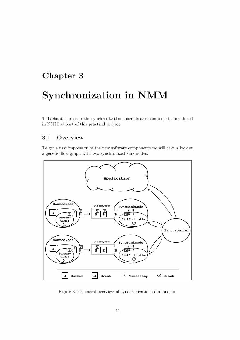
To get a first impression of the new software components we will take a look ata generic flow graph with two synchronized sink nodes.
Synchronizer
SyncSinkNode
SinkController
Application
SyncSinkNode
SinkController
StreamQueue
T
B TB BT
B
B
T
Stream-Timer
SourceNode
TT
B
BStream-Timer
SourceNode
TT
B
StreamQueue
T
B E B T
EBuffer Event Timestamp Clock
Figure 3.1: General overview of synchronization components
11
CHAPTER 3. SYNCHRONIZATION IN NMM 12
This graph only contains four nodes: two source nodes and two sink nodes.One can see the fundamental objects that will be explained in this chapter:Clocks, Timestamps, StreamTimer, Controller, SyncSinkNodes and Syn-
chronizer.All components that want to have access to a Clock are subclasses from
TimedElement; they share a common Clock that is a static member of Timed-Element. Timestamps contain the time information for a data buffer. TheStreamTimer is an object that can be used by nodes to simplify timestampcreation. All synchronized sink nodes are subclasses of GenericSyncSinkNode.These nodes come along with a Controller. They pass the timestamps ofincoming buffers to their controller which decides what to do with this buffer:Present it immediately, wait some time until presentation or discard the bufferbecause it arrived too late at the sink node. One can say that the controllerrealizes the intra-stream synchronization. If you want to combine multiplestreams, the controllers of the sink nodes are connected to a Synchronizer
object which realizes the inter-stream synchronization. It also serves as aninterface for the application which can pause or wakeup the presentation viathe synchronizer.
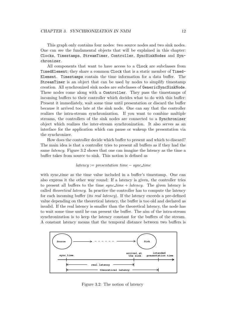
How does the controller decide which buffer to present and which to discard?The main idea is that a controller tries to present all buffers as if they had thesame latency. Figure 3.2 shows that one can imagine the latency as the time abuffer takes from source to sink. This notion is defined as
latency := presentation time − sync time
with sync time as the time value included in a buffer’s timestamp. One canalso express it the other way round: If a latency is given, the controller triesto present all buffers to the time sync time + latency. The given latency iscalled theoretical latency. In practice the controller has to compute the latencyfor each incoming buffer (its real latency). If the latency exceeds a pre-definedvalue depending on the theoretical latency, the buffer is too old and declared asinvalid. If the real latency is smaller than the theoretical latency, the node hasto wait some time until he can present the buffer. The aim of the intra-streamsynchronization is to keep the latency constant for the buffers of the stream.A constant latency means that the temporal distance between two buffers is
sync_timeintended
presentation time
theoretical latency
Source Sink
real latency
arrival at the sink
Figure 3.2: The notion of latency
CHAPTER 3. SYNCHRONIZATION IN NMM 13
equal to the difference of their sync time, and so they are presented with theintended velocity.
The controller also computes an average value of the latency of incomingbuffers. With this value it is possible to compare the latencies of two or moremultimedia streams. This is the part of the synchronizer: If the average latencyof a stream changes, the synchronizer computes a new theoretical latency totake these changes into account. The aim of this inter-stream synchronizationis that the latencies for the different streams are equal. The easiest way toreach this is to set the theoretical latency to the maximal average latency of allstreams: Then the streams with a small latency have to wait until their latencyhas reached the value from the “slower” ones.
This should give a first impression of how synchronization works in NMM.Before going into details, we first have to take a look at some elementary datastructures that are used by synchronization.
3.2 Elementary data types
To represent points of time, time durations and frame rates and to put sometime information into a multimedia stream there are some elementary datatypesin NMM.
3.2.1 Rational numbers
All frame rates or time durations in multimedia applications are measured byclocks and are therefore of limited precision. One can express them as rationalnumbers. Therefore the class Rational for representation and basic arithmeticfunctions of rational numbers has been added to NMM. It stores a rationalnumber as
class Rational {
long int numerator;
long int denominator;
};
Note that the numerator carries the sign information for the fraction; the de-nominator is always greater than zero. If the denominator reaches the valuezero during a computation, a RationalDivisionByZeroException is thrown.
3.2.2 Time representation - Time, Interval and UserTime
There are two types for representation of time in NMM. Time represents apoint of time, Interval stands for a duration (which can be considered asthe difference between two points of time.) Both Time and Interval have aprecision of one nanosecond. They are internally stored as
struct Time { struct Interval {
long int sec; long int sec;
long int nsec; long int nsec;
}; };
CHAPTER 3. SYNCHRONIZATION IN NMM 14
where the variable nsec is bounded by the values 0 and 109− 1 and sec
can take all possible values, both positive and negative. To bound the nsec
value makes comparison and elementary arithmetical operations for Time andInterval faster by reducing the number of cases to distinguish. A precision ofone nanosecond was chosen to gain compatibility to the OpenML – Standard(see [7]). One should note that the precision of the clocks available at the mo-ment is smaller than one microsecond. We have seen in section 1.3 that such aprecision suffices for the main synchronization purposes.
As described in [14] (page 81), it is guaranteed that a long int has at least32 bits. This ensures that both of the types have a range of about 68 yearsin the past and the future. At the moment this should be sufficient for everymultimedia application.
The main idea behind the separation between points of time and intervalswas to gain a typesafe interface for time calculations. A set of standard op-erators comes along with the two types, and so it should not be necessary tomanipulate them at low level.
There is also a type to provide a human readable time representation:UserTime. This is meant to be used in time displays in various applications. AUserTime consists of the following members:
struct UserTime {
int hour;
int min;
int sec;
int msec;
};
The precision of one millisecond for UserTime should suffice for the intendedusage as time display.
3.2.3 Time information in the multimedia stream - Timestamp
In most of the applications it is necessary to send some time information withinthe data stream. For this reason the class Message has a Timestamp as membervariable. A Timestamp is build up like this:
struct Timestamp {
Time sync_time;
long int stream_counter;
bool is_valid;
};
The sync time carries the time information. Usually it marks the intended be-ginning of the presentation of the buffer’s media content. The stream counter
simply counts the data buffers in the stream. The flag is valid indicates if thetime value has been set correctly. This is necessary because you do not alwayshave enough information to set the timestamp for each outgoing buffer correctly.For example, a generic source node that reads different kinds of formats from
CHAPTER 3. SYNCHRONIZATION IN NMM 15
a hard disc does not have the knowledge to extract the time information forevery format. With this flag it can indicate that a buffer’s timestamp containsno useful time information. A specific decoder node then can compute the righttime values. You can get and set a message’s timestamp with the two methods
void setTimestamp(const Timestamp timestamp);
Timestamp getTimestamp();
from the class Message. Although the timestamps are contained in a generalmessage, they are only in use for data buffers and not for events at the mo-ment (as shown in figure 3.1). The concept of a timestamp is similar to SGI’sUnadjusted System Time (see [11] for details).
3.3 Objects in the graph
3.3.1 Clock and TimedElement
TimedElement is the superclass for all objects that want to have access to atime source. All TimedElements of one application share one global and staticClock object and therefore have access to the same time. The shared access toone clock is the reason why there is no possibility to change the clock’s value.They can get the current time with the method
Time getTime();
The Clock is a static member of the class TimedElement and is therefore auto-matically created and destroyed. At the moment there’s only one kind of Clockthat uses the internal system clock.
On a local system it might be interesting to use another timebase, especiallyin the context of continuous media played by an internally buffered device. Thesimplest and also the best example for this situation is given by a sound device.The soundcard chip uses its own internal timebase that is not synchronized withthe computers clock. So there can be a slight skew between these two clocks. Ifwe only rely on the computer’s internal clock, this skew can be noticeable overa long presentation. This problem could be solved by using the sound devicesclock instead of the computers clock as timebase for audio and video.
The first and obvious problem with this approach is that in most of thecases one does not even have direct access to the sound devices internal clock.Another problem appears in context of a network environment: Here the twosink nodes must not necessarily be located on the same computer. The questionarises how to synchronize the video sink computer with the clock of the sounddevice, because this includes synchronization via network connections.
It suffices as a first step to use the computer’s hardware clock as timebase.The Network Time Protocol (NTP) is used to reduce the clock skew betweenthe different machines in the network.
CHAPTER 3. SYNCHRONIZATION IN NMM 16
3.3.2 Timestamp creation - StreamTimer
Nodes that want to create timestamps for a data stream can use a StreamTimer.A StreamTimer has two different modes, REAL TIME and CONST RATE. You canchoose the mode with the method
Result setMode(const Mode mode);
In the REAL TIME mode the StreamTimer uses the common clock to create thetimestamps. This mode is meant to be used in nodes for life-sources like acamera or a microphone. Although most of these sources offer the possibilityto choose a frame- or buffer rate, the chosen rates cannot always be kept. So itseems to be better to use the computer’s clock to get the timestamp informationfor incoming buffers instead of relying on what we have chosen as framerate.This is just what the StreamTimer does in CONST RATE mode. You can set aframe rate or an inter-frame-gap, and the timestamps are simply computed asincreasing values from 0 on and regarding this constant rate. This can be usefulif you know the exact frame rate, e.g. in a video stream read from disc, butthe stream does not have timestamps yet. The interval between two followingbuffers can be set with the two methods
Result setRate(const float rate);
Result setInterval(const Interval interval);
where the first method uses the buffer rate and the second the interval betweentwo following buffers.
For both of the modes the StreamTimer sets the timestamps into the mes-sages when the following method is called:
Result setTimestamp(Message* message);
Note that this method has the side-effect of increasing the internal timestampvalue of the StreamTimer to make it right for the next buffer. So it should becalled only once for each buffer.
3.3.3 GenericSyncSinkNode and its subclasses
The superclass for all sink nodes that are capable to be synchronized is calledGenericSyncSinkNode. Instead of the Buffer* processBuffer(Buffer*) -methods from the other nodes, these have the two methods
void prepareBuffer(Buffer* in_buffer);
void presentBuffer(Buffer* in_buffer);
In the prepareBuffer(Buffer*)-method, all time-wasting preparations for thepresentation of the buffer should happen. For example, a video display nodecould copy the next frame in a shared memory region used by the X windowsystem. In other cases, this method is not used and then simply should not beoverloaded.
CHAPTER 3. SYNCHRONIZATION IN NMM 17
In the presentBuffer(Buffer*)-method the presentation should happen assoon as possible. The idea behind this is that the presentBuffer(Buffer*)-method can be triggered right at the time the presentation should happen. Thevideo display node sets the flag for presentation of the next frame in this method.Surely this is only an approximation: There is always a small duration betweenthe presentBuffer(Buffer*)-call and the actual presentation, but this timeinterval is neglected.The method
setSynchronized(bool);
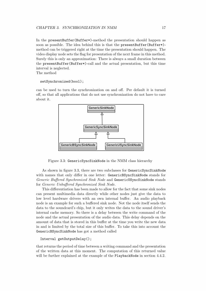
can be used to turn the synchronization on and off. Per default it is turnedoff, so that all applications that do not use synchronization do not have to careabout it.
GenericSinkNode
GenericSyncSinkNode
GenericBSyncSinkNode GenericUSyncSinkNode
Figure 3.3: GenericSyncSinkNode in the NMM class hierarchy
As shown in figure 3.3, there are two subclasses for GenericSyncSinkNodewith names that only differ in one letter: GenericBSyncSinkNode stands forGeneric Buffered Synchronized Sink Node and GenericUSyncSinkNode standsfor Generic Unbuffered Synchronized Sink Node.
This differentiation has been made to allow for the fact that some sink nodescan present multimedia data directly while other nodes just give the data tolow level hardware drivers with an own internal buffer. An audio playbacknode is an example for such a buffered sink node. Not the node itself sends thedata to the soundcard’s chip, but it only writes the data to the sound driver’sinternal cache memory. So there is a delay between the write command of thenode and the actual presentation of the audio data. This delay depends on theamount of data that is stored in this buffer at the time you write the new datain and is limited by the total size of this buffer. To take this into account theGenericBSyncSinkNode has got a method called
Interval getOutputDelay();
that returns the period of time between a writing command and the presentationof the written data at this moment. The computation of this returned valuewill be further explained at the example of the PlaybackNode in section 4.4.2.
CHAPTER 3. SYNCHRONIZATION IN NMM 18
We have already seen in section 3.1 that each GenericSyncSinkNode has aController as member variable. The main difference between the unbufferedand buffered node is that they have different controllers. These will be furtherexplained in section 3.3.4.
The following code sample taken out of GenericSyncSinkNode shows whatsuch a node does with an incoming buffer:
timestamp = in_buffer->getTimestamp();
if( !(controller -> isBufferValid(timestamp))) {
// if the buffer is too old or invalid, release it
in_buffer -> release();
} else {
// otherwise, prepare it for presentation
prepareBuffer(in_buffer);
// wait until the time for presentation has come ...
suspendThread(controller -> waitToPresent(timestamp));
// and present it!
presentBuffer(in_buffer);
}
3.3.4 Controller and its subclasses
As we have seen in the last section, each GenericSyncSinkNode has its ownController which tells the node what to do with an incoming buffer: discardit, present it directly or present it after waiting some time. This controller is amember of its parent node and therefore a local object from the node’s point ofview. So the communication between node and controller can use simple andfast function calls. Like the corresponding sink node types there are differentclasses for Buffered Sink Controller and Unbuffered Sink Controller.
We have already described some of the internal parameters like real latencyin section 3.1. Now a more detailed description will be given.
The controller gets the timestamp of each incoming buffer with the call ofthe method bool isBufferValid(Timestamp) by the GenericSyncSinkNodeshown in the source code example above. We now explain what the controllerdoes in this method:
For each incoming buffer the controller computes the real latency as thedifference between the earliest possible presentation time and the buffer’s synctime. An USinkController assumes that the node has no internal buffer andcan present the data immediately. The controller therefore uses the currenttime as approximation of the presentation time and computes the real latencyas follows:
real latency := current time − sync time.
CHAPTER 3. SYNCHRONIZATION IN NMM 19
Controller
+isBufferValid(timestamp:const Timestamp): bool+checkBufferValid(timestamp:const Timestamp): bool
SinkController+theo_latency: Interval+average_latency: Interval+average_count: int+max_delay: Interval+max_average_delay: Interval+max_disc: int+waitToPresent(timestamp:const Timestamp): Interval+checkBufferValid(timestamp:const Timestamp): bool+setMaxDelay(max_delay:const Interval): Result+setMaxAverageDelay(max_average_delay:const Interval): Result+setTheoLatency(theo_latency:const Interval): Result+setAverageCount(average_count:int): Result+setMaxDiscardingCount(max_discarding_count:int): Result
BSinkController
+checkBufferValid(timestamp:const Timestamp): bool+waitToPresent(timestamp:const Timestamp): Interval
USinkController
+checkBufferValid(timestamp:const Timestamp): bool+waitToPresent(timestamp:const Timestamp): Interval
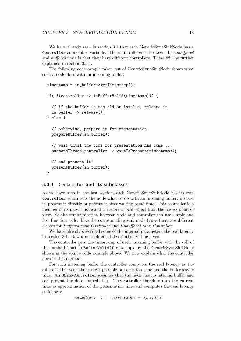
Figure 3.4: The class hierarchy for Controller and its subclasses
A BSinkController assumes that its parent node has an internal buffer. A databuffer can not be presented before the presentation of the internal buffer’s datahas been finished. We will call the duration of this presentation the output delay.Therefore a BSinkController uses the formula
real latency := current time + output delay − sync time
to compute the real latency of each buffer.After the computation the real latency is used to decide whether the buffer
should be presented or discarded: If the real latency is greater than
theo latency + max delay
the buffer is declared as invalid. Here max delay is the limit for the maximaldelay of one single buffer, and theo latency is a value set by the synchronizer(see section 3.3.5). Max delay can be set with the member function
Result setMaxDelay(Interval);
If we want to keep the requirements for lip synchronization in section 1.3.2, atypical value for max delay is 80 milliseconds. The theo latency is updated bythe synchronizer with the member function
Result setTheoLatency(Interval);
Both of the controller types compute an average value out of the incomingbuffer’s real latencies. If r1, . . . , raverage count are the real latencies for the lastaverage count buffers, then the average latency is computed as
average latency :=r1 + . . . + raverage count
average count.
The number of buffers that are taken into account for such a computation canbe set by the member function
CHAPTER 3. SYNCHRONIZATION IN NMM 20
Result setAverageCount(int);
The number of buffers surely has an influence on the reaction time of the syn-chronization system. Typical values are 10 buffers for video streams and 20buffers for audio streams.
Similar to the real latency, the controller also checks if the average latency isgreater than theo latency + max average delay. In this case it calls the method
Result setAverageLatency(Interval, SinkController*);
from the synchronizer. This has no influence on the question if the last bufferis considered as valid or invalid. The average latency value is used by thesynchronizer to update the value for the theoretical latency (see section 3.3.5).Typical values for the max average delay range from 20 to 40 milliseconds. ABSinkController also informs the synchronizer if its average latency is gettingsmaller. For example, this can happen if the soundcard’s internal clock is a bitslower than the computer’s clock and the sample rate is not kept exactly. Sothe synchronizer has to take this into account to keep audio and video together.
Not every buffer that has been declared as invalid so far should be discarded.To avoid discarding of too much immediately following buffers the controllercounts how many buffer it has considered as invalid after each other. If thisnumber exceeds the value max disc, the buffer will be presented even if it is tooold. This makes sense for a video presentation: If each third frame has to bepresented, one gets an impression of the motions in the video even if not everyframe is displayed. This value has no influence on discarding all buffers in thestate WAIT FOR RESET (see section 3.4.2). It is set with the member function
Result setMaxDisc(int);
Note that a value of zero causes the controller to declare all buffers as valid.This is useful for audio playback: Discarding an audio buffer causes unwantednoise output.
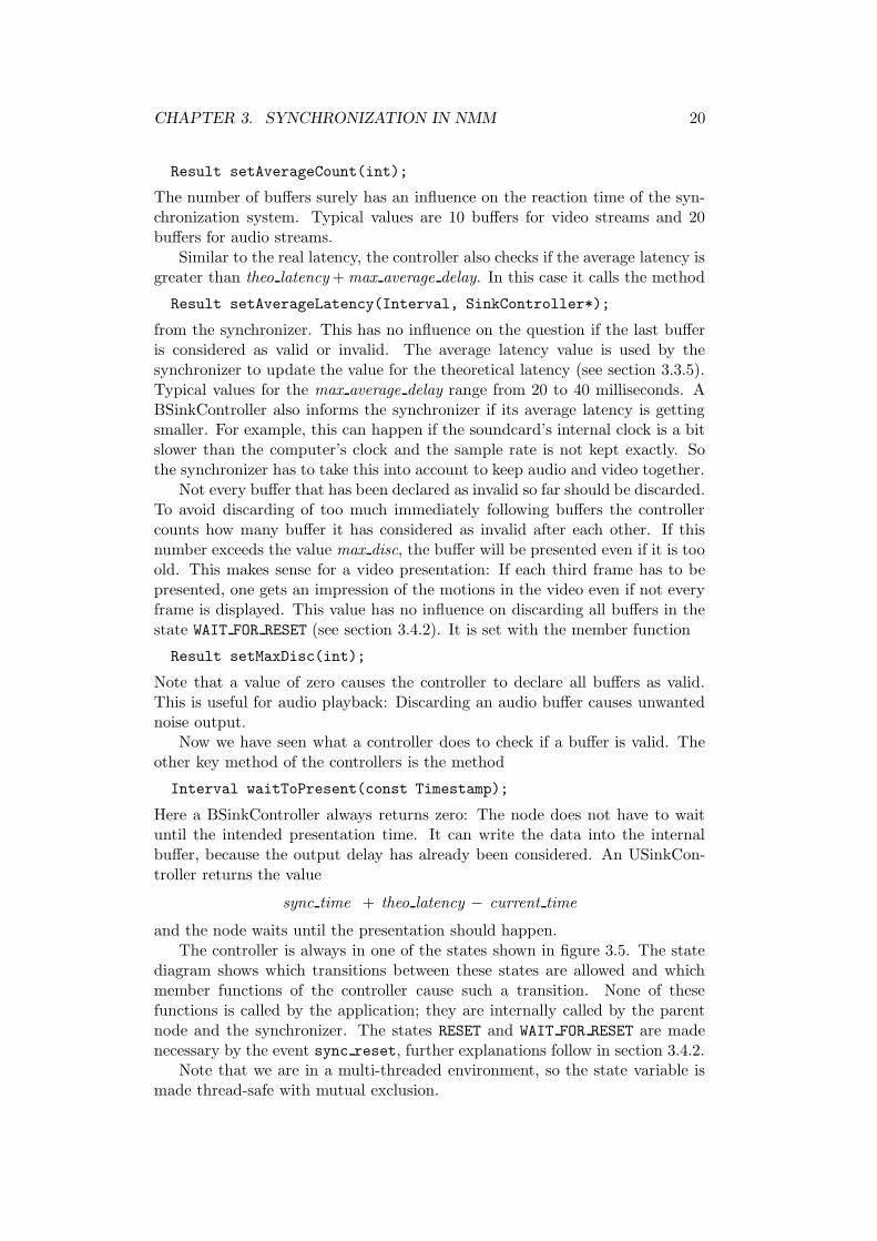
Now we have seen what a controller does to check if a buffer is valid. Theother key method of the controllers is the method
Interval waitToPresent(const Timestamp);
Here a BSinkController always returns zero: The node does not have to waituntil the intended presentation time. It can write the data into the internalbuffer, because the output delay has already been considered. An USinkCon-troller returns the value
sync time + theo latency − current time
and the node waits until the presentation should happen.The controller is always in one of the states shown in figure 3.5. The state
diagram shows which transitions between these states are allowed and whichmember functions of the controller cause such a transition. None of thesefunctions is called by the application; they are internally called by the parentnode and the synchronizer. The states RESET and WAIT FOR RESET are madenecessary by the event sync reset, further explanations follow in section 3.4.2.
Note that we are in a multi-threaded environment, so the state variable ismade thread-safe with mutual exclusion.
CHAPTER 3. SYNCHRONIZATION IN NMM 21
WORKING The default state for the controller.RESET The controller has received a reset()-call. All inter-
nal parameters are set to their default values.WAIT FOR RESET In this state the controller declares all data buffers as
invalid until the next reset()-call arives. Then it willget to state WORKING again.
PAUSE The controller has stopped its parent node and waitsuntil the wakeup()-method is called.
PAUSE
WAIT_FOR_RESET
WORKING RESETreset
restartwaitForReset
reset
pause wakeup
Figure 3.5: States and state transitions of a Controller
3.3.5 Synchronizer
So far we have only considered synchronization that refers to one multime-dia stream and not introduced the link between multiple streams. This linkis constructed via the Synchronizer object which is connected to the con-trollers of all sink nodes that should be kept in sync. The synchronizer realizesinter-stream synchronization it is therefore not related to a special node. Itis created once for the application with two or more sink nodes for which itencapsulates the synchronization strategy. One can build a new subclass ofSynchronizer if the existing ones do not fit to the requirements of the streamconstellation in the actual application. At the moment the only subclass ofSynchronizer is the AudioVideoSynchronizer which is designed for generalaudio/video presentations. The synchronizer is also thought as a central accesspoint for run-time synchronization control: For example, the application cansent pause and wakeup signals to the synchronizer.
The main task of the synchronizer is to keep the average latencies of allconnected sink controllers equal. For this reason it has to react to incomingaverage latency values. If a controller calls the method
Result setAverageLatency(Interval, SinkController*);
the synchronizer checks if it is necessary to update the theo latency. We havealready seen in section 3.1 that one strategy is to simply take the maximum ofthe old value for theo latency and the incoming average latency.
The AudioVideoSynchronizer also takes into account that the connectedsink nodes present audio and video: Here the theoretical latency is set to the
CHAPTER 3. SYNCHRONIZATION IN NMM 22
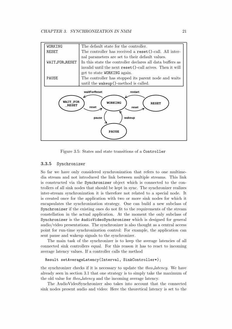
audio average latency to make the video stream fit to the audio stream.Like a controller, a synchronizer also has got different states. These are
shown in figure 3.6. Note that the pause()- and wakeup()-methods are calledby the application; the reset()-method is called internally by the connectedcontrollers. See section 3.4.2 for further information about the state RESET.
WORKING The default state for the Synchronizer.RESET The Synchronizer has received a reset()-call from one of
the connected Controllers. All internal parameters are setto their default values.
PAUSE The Synchronizer takes the current time and switches thestate of all connected Controllers to PAUSE.
WORKINGreset
resetpause
wakeupPAUSE RESET
Figure 3.6: States and state transitions of a Synchronizer
3.4 Events related to synchronization
At the moment there are three events that refer to synchronization. Theyserve to enable and disable synchronization or reset the internal parameters ofsynchronization components. They are typically sent in-stream: It is the onlyway to make sure that they can bring their effects after the presentation of acertain buffer.
3.4.1 sync enable and sync disable
The first two events, sync enable and sync disable, have only an effect onsynchronized sink nodes (i.e. all subclasses of GenericSyncSinkNode). Theyhave the same functionality as a call of the setSynchronized(bool)-method.This way it is possible to disable or enable the synchronization after or beforethe presentation of a certain buffer. In the constructor of GenericSyncSink-Node the two accompanying event handler methods are registered which arecalled
Result eventSyncEnable();
Result eventSyncDisable();
These methods simply call the setSynchronized(bool)-method with the rightarguments.
CHAPTER 3. SYNCHRONIZATION IN NMM 23
3.4.2 sync reset
The third event, sync reset, is also handled by many other nodes (includingMPEGDemuxNode, MPEGVideoDecodeNode, MPEGAudioDecodeNode, AC3Decode-Node etc.). All of these register a handling method called eventSyncReset().See [1] and [4] to get to know more about these nodes. Section 4.6 describesthe synchronization related aspects that are connected with them.
Source-Node
Demux-Node
SinkNode 1
SinkNode 2E
BE B
BBB BB
B BB
E
E
E
old timebase
newtime-base
new timebaseoldtime-base
inconsis-tent
Timestamps
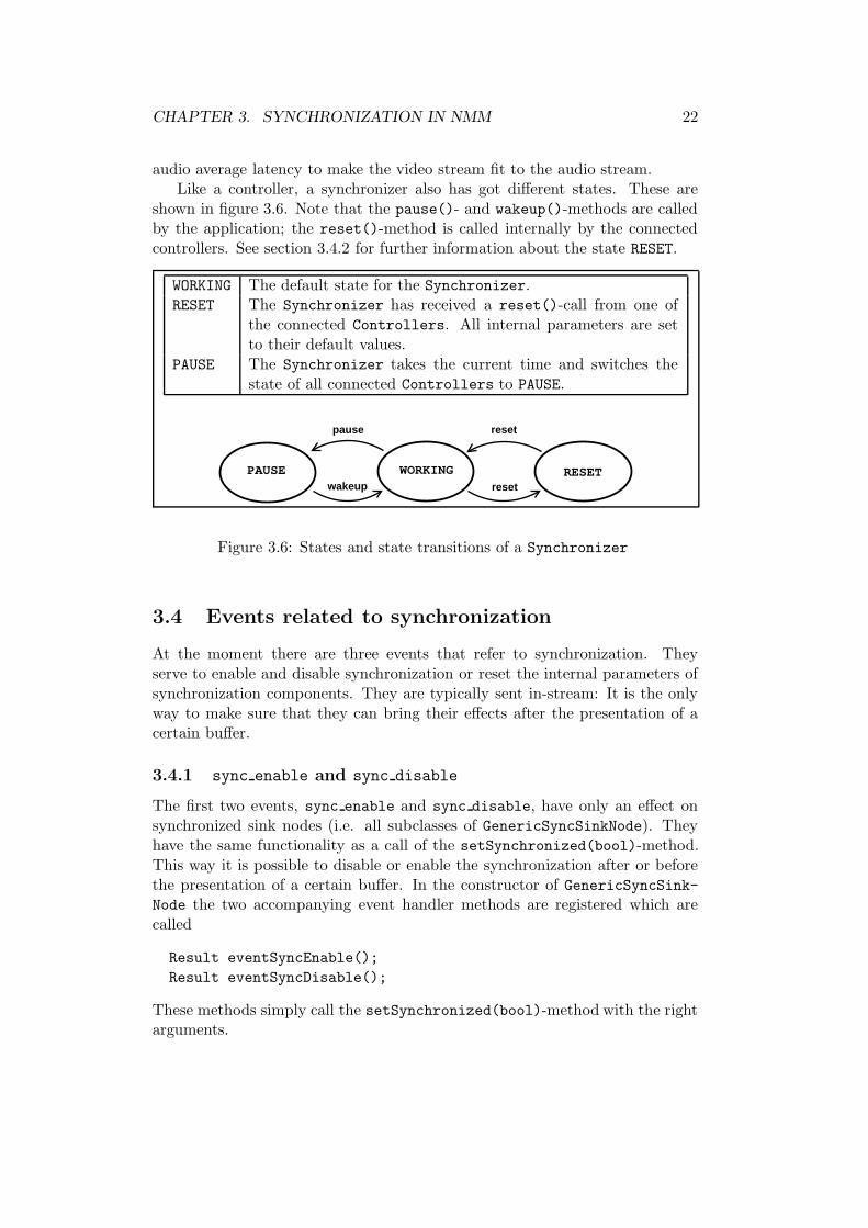
Figure 3.7: Problems with different path lengths
The event sync reset is used to indicate that the parameters of synchro-nization should be reset. For example, this is necessary if you switch to anotherchannel on TV or if you choose a new chapter in the DVD application. Inboth cases, the timestamps in the new MPEG stream are not related to thetimestamps read before. Therefore one resets all internal parameters and usesthe new values from now on.
Figure 3.7 shows the problem that occurs when an in-stream-event generatedby a single source is duplicated by a demultiplexer node. The different pathlength causes that the both copies of the event appear at the sinks at differenttimes. That can cause problems for all events that need to be worked upat all sinks at the same time. In the case of a sync reset-event this leadsto inconsistent timestamp values: One controller has already reset internalparameters and receives new timestamps, the other still receives old timestamps.
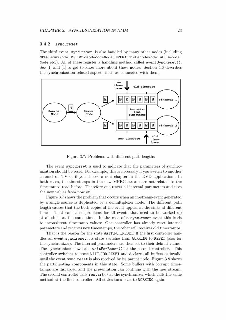
That is the reason for the state WAIT FOR RESET: If the first controller han-dles an event sync reset, its state switches from WORKING to RESET (also forthe synchronizer). The internal parameters are then set to their default values.The synchronizer now calls waitForReset() at the second controller. Thiscontroller switches to state WAIT FOR RESET and declares all buffers as invaliduntil the event sync reset is also received by its parent node. Figure 3.8 showsthe participating components in this state. Some buffers with corrupt times-tamps are discarded and the presentation can continue with the new stream.The second controller calls restart() at the synchronizer which calls the samemethod at the first controller. All states turn back to WORKING again.
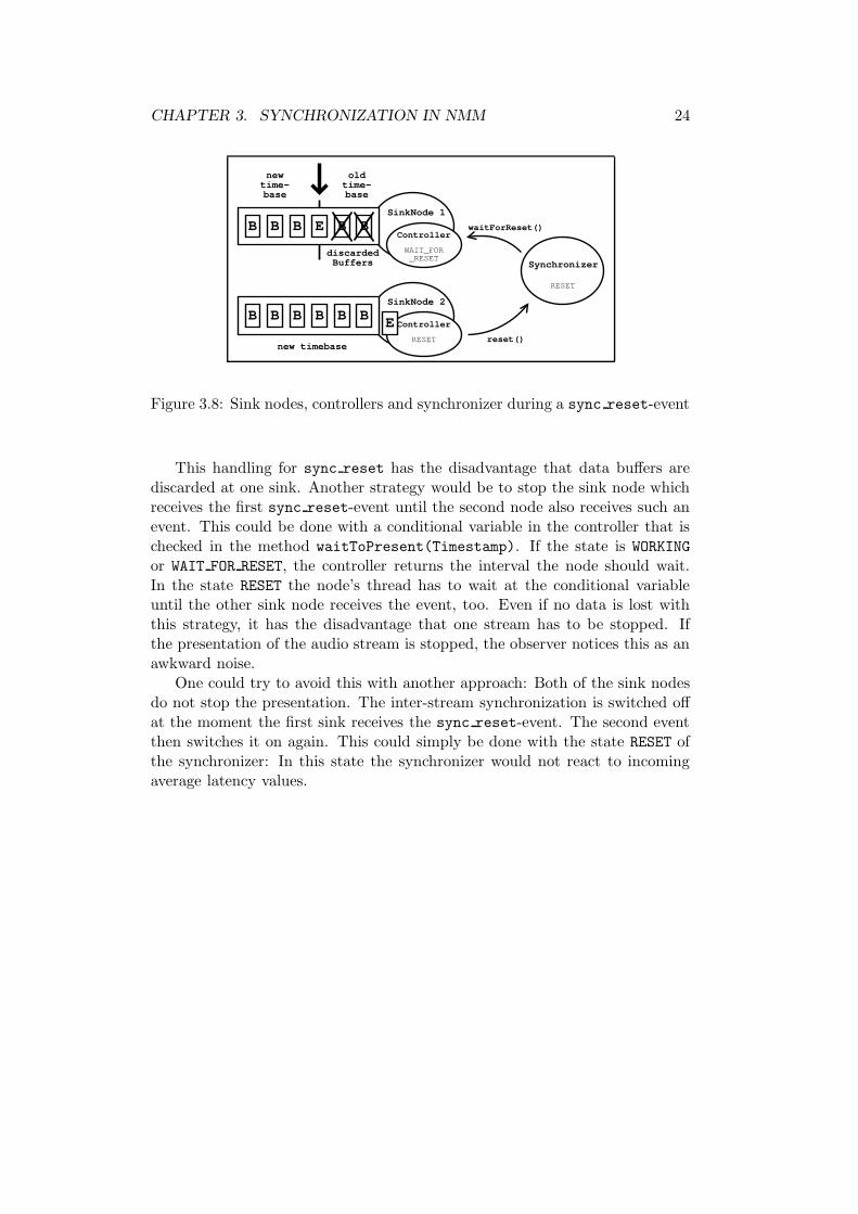
CHAPTER 3. SYNCHRONIZATION IN NMM 24
SinkNode 1
SinkNode 2
E
BBB BB
BBB
newtime-base
new timebase
B
oldtime-base
B B
discardedBuffers Synchronizer
Controller
Controller
reset()
waitForReset()
RESET
RESET
WAIT_FOR_RESET
E
Figure 3.8: Sink nodes, controllers and synchronizer during a sync reset-event
This handling for sync reset has the disadvantage that data buffers arediscarded at one sink. Another strategy would be to stop the sink node whichreceives the first sync reset-event until the second node also receives such anevent. This could be done with a conditional variable in the controller that ischecked in the method waitToPresent(Timestamp). If the state is WORKING
or WAIT FOR RESET, the controller returns the interval the node should wait.In the state RESET the node’s thread has to wait at the conditional variableuntil the other sink node receives the event, too. Even if no data is lost withthis strategy, it has the disadvantage that one stream has to be stopped. Ifthe presentation of the audio stream is stopped, the observer notices this as anawkward noise.
One could try to avoid this with another approach: Both of the sink nodesdo not stop the presentation. The inter-stream synchronization is switched offat the moment the first sink receives the sync reset-event. The second eventthen switches it on again. This could simply be done with the state RESET ofthe synchronizer: In this state the synchronizer would not react to incomingaverage latency values.
Chapter 4
Synchronization in Plug-insand Applications
After describing the underlying datatypes and architecture we will have a lookat some practical examples of how synchronization takes place in plug-in nodesand applications. The functionality of these nodes is described rather shortlyhere. For further information how the nodes work, please refer to [4]. At first wewill describe the timestamp handling for some general node classes. We will dothis in the order of appearance of the nodes in a flow graph: From source nodesover filter or converter nodes to the sink nodes. We will especially describe thesink nodes as concrete node examples because almost every example applicationcontains one of the presented sink nodes. Then we will have a closer lookat two examples for synchronization in application programming: The audiovisualization examples have been written as part of this practical project, theMPEG decoding examples were just extended by the synchronization part. See[4] to learn more about the MPEG decoding example and the participatingnodes.
4.1 Source nodes
One can distinguish between live sources and “artificial” sources. Live sourcesget their data from a device that captures it at that moment like a video cameraor a microphone. Artificial sources read data that was created before and storedfrom hard disc, DVD or from other data sources. The main difference accordingto synchronization is that live sources have to create timestamps for outgoingbuffers while the data read from artificial sources needs to contain some timeinformation in order to allow synchronization. Therefore we will have a closerlook at the timestamp creation in live sources.
4.1.1 Live sources
The live sources always use a StreamTimer for timestamp creation as describedin the last chapter. For this reason the nodes simply create a StreamTimerobject in the REAL TIME-mode and tell it to set the timestamp of each outgoing
25
CHAPTER 4. PLUG-INS AND APPLICATIONS 26
buffer in the produceBuffer()-method. The following code sample shows howthis works for a plug-in node called Source:
Source() {
// ...
StreamTimer timer = new StreamTimer(StreamTimer::REAL_TIME);
}
~Source() {
// ...
delete timer;
}
Buffer* produceBuffer() {
Message* out_buffer = getNewBuffer(out_buffer_size);
// produce the data content and
// put it into the out_buffer
timer->setTimestamp(out_buffer);
return out_buffer;
}
An example for such a live source is the RecordNode that uses the OSSaudio driver (see [2]) to read audio data from the sound device. Another livesource node example is the GenericFireWireNode which can be used to recorda video stream from a camera connected to the IEEE 1394 bus.
4.2 Filter nodes
This class of nodes is characterized by the fact that the format of incomingand outgoing data and buffer quantities are equal. For example, a node thatdisplays a logo in the upper left corner of each incoming video frame belongsto this cathegory. Another obvious example is a sound effects node. Both ofthem sent one buffer with the same format for each buffer they receive.
These nodes normally do not need to know something about presentationtime or duration of incoming buffers. They only copy the timestamp of anincoming buffer into the corresponding outgoing buffer they produce. This isdone automatically by the member function
Buffer* getNewBuffer(const size_t size, Buffer* in_buffer);
which is defined in the class IExternalBufferManager and returns a new bufferwith the expected size and the same timestamp as the in buffer.
4.3 Converter nodes
It is characteristic for a converter node that its input format is not equal toits output format. This holds for a large spectrum of nodes. Not all of the
CHAPTER 4. PLUG-INS AND APPLICATIONS 27
converters have to change something at the buffer’s timestamps: One maythink of a node that converts video frames from an YUV colorspace to RGB.From the synchronization point of view, these examples behave like the filternodes in the last section.
The example shown above only deals with raw formats: There are alsocompressed formats like MPEG or AVI which come along with their own formatspecific time information. Some nodes have to convert this time informationinto values that can be used as timestamps in NMM or otherwise. The otherdifference to a filter node is that for a converter node there is not always aone-to-one correspondence between incoming and outgoing buffers.
In section 4.5 we will describe two nodes for which the assumption of such acorrespondence fails: the audio visualization nodes. In section 4.6 we will focuson the nodes taking part in MPEG decoding.
4.4 Sink nodes
Most of the changes due to synchronization have been done in the sink nodes.Some of these changes have been explained already in the last chapter, but nowwe will see their influence on already existing nodes.
4.4.1 Video sinks
At the moment there are three video sinks available for NMM which are inher-ited from GenericUSyncSinkNode: The XDisplayNode, the MatroxDisplayNo-de and the GLDisplayNode. The XDisplayNode is the usual display node thatcommunicates with the X server while the MatroxDisplayNode uses a specialdevice and driver. See [4] to get to know more about these sink node. TheGLDisplayNode finally uses OpenGL to display incoming frames. The synchro-nization related part of these nodes is very similar. With the inheritance fromGenericUSyncSinkNode there is no need for big changes in the plug-in nodes.
The main idea is to copy the next frame into a suitable memory regionin the prepareBuffer(Buffer*)-method. For the XDisplayNode and the Ma-troxDisplayNode this is done by a real memory copy operation. They copy theimage data into an X shared memory or a special memory region of the driver.The GLDisplayNode creates a texture out of the data in this method.
The presentBuffer(Buffer*)-method then just gives the command tochange the presented image. The nodes do this with special functions fromthe X server, the Matrox driver or OpenGL.
4.4.2 Audio sinks
The NMM audio sink is called PlaybackNode. It uses the Open Sound System(OSS) audio drivers to get access to the sound device. See [2] for details abouthow to use the OSS drivers.
In this case we have an example for a buffered sink node since the OSSdriver allocates an internal data buffer. Therefore PlaybackNode is a subclassof GenericBSyncSinkNode.
CHAPTER 4. PLUG-INS AND APPLICATIONS 28
Besides the extensions for synchronization, the PlayBackNode has been ex-tended by automatical recognition of supported audio formats. Raw audioformats are build up with the following parameters:
• sample rate: The number of samples per second. Usual values are between8kHz and 96kHz.
• bit per sample: The number of bits that build one sample. Normally thisvalue will be 16.
• number of channels: This number can vary between 1 and 6.
• sample representation: This refers to the byte order depending on theprocessor architecture and is often refered as big endian or little endian.
The PlaybackNode automatically tests which combinations of these values aresupported by the soundcard.
To get synchronized we need some methods to get to know the delay causedby the data in the internal buffer. Because the sampling rate does not changewhile the driver is playing this is equivalent to get to know the number of bytesthat are stored in the internal buffer at the moment. The OSS drivers offer dif-ferent ioctl()-calls to solve this problem. The are called GETOSPACE, GETOPTRand GETODELAY. I have made the experience that they are not equivalently. TheGETODELAY-call gave the best results. All of the functions have one problem incommon: The internal buffer is separated in so-called fragments that are usedby the driver for double-buffering to avoid a data leak at the soundcard. Whenyou start to write audio data to the device, the driver starts the presentationafter the first fragment is filled. The delay values returned by the three methodsare zero until the presentation has been started, although data has been alreadywritten to the device. Therefore it is sensible to work with small fragment sizes.Per default the driver uses two fragments with 65536 bytes per fragment for allsound cards we have tested. The PlaybackNode tries to configure the driver touse an internal buffer of up to 16 fragments with 4096 bytes per fragment. Thesound driver can override these values depending on the hardware’s capabilities.The internal buffer size means that 16 ∗ 4096/(48000 ∗ 2 ∗ 2) = 0.341 seconds ofaudio can be stored in this buffer with a sample rate of 48 kHz, stereo and 16bit per sample. We note that the consideration of this internal buffer plays animportant role to gain audio/video synchronization.
With the number of bytes bytes in buffer in the internal buffer one cansimply compute the duration t buf of playing the internal buffer’s content:
t buf =bytes in buffer
sample rate · bytes per sample
Here the value bytes per sample is defined as
bytes per sample = number of channels · bit per sample.
If we write a data buffer to the device at the time now, the observer will hearit at the time now + t buf. So this interval t buf is computed and returned bythe getOutputDelay()-method.
CHAPTER 4. PLUG-INS AND APPLICATIONS 29
See [2] and the source code file PlaybackNode.cpp in the NMM distributionfor more details about the programming internals.
In the PlaybackNode there is nothing to do for a prepareBuffer - method,and it is therefore left empty. The only thing the PlaybackNode does with in-coming audio data is to write it to the sound device in the presentBuffer(Buf-fer*)-method.
4.5 Audio visualization
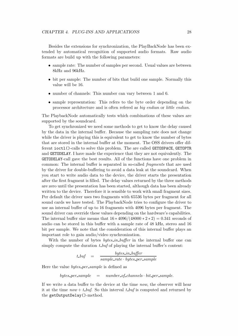
4.5.1 The mp3vis and mp3vis2 applications
There are two example applications that play MPEG 2 Layer 3 encoded au-dio files and visualize the audio data. Both of the applications are build upwith six nodes, and their graphs only differ in the node used for visualiza-tion. The application mp3vis uses the ScopeNode while mp3vis2 makes use of aSAnalyzerNode. Figure 4.1 shows the graph of mp3vis or mp3vis2, respectively.You simply need to replace VisNode with a ScopeNode or a SAnalyzerNode toget the graph of mp3vis and mp3vis2 out of it.
MP3Read-Node
MPEGAudio-DecodeNode
VisNode XDisplay-Node
Playback-Node
CopyNodeAudioVideo-Synchronizer
Application
VisNode stands for ScopeNode or SAnalyzerNode.
Figure 4.1: The graph of the MP3 visualization examples
The source node is an MP3ReadNode to read the compressed audio datafrom the hard disc. This reader is connected to an MPEGAudioDecodeNode thatdecodes the MP3-compressed data into raw audio data. After the decoder themultimedia stream has to be split up into two streams, one for the audio outputand one for the visualization. This is done by a CopyNode which simply sendsincoming buffers to both of its output jacks. One of them is connected directlyto the PlaybackNode, an audio sink node which uses the OSS audio driver. Theother output jack leads to the VisNode. The VisNode itself is connected to thevideo sink, the XDisplayNode. The MPEGAudioDecodeNode and the VisNode
are the two nodes in this graph that create and set the timestamps into the
CHAPTER 4. PLUG-INS AND APPLICATIONS 30
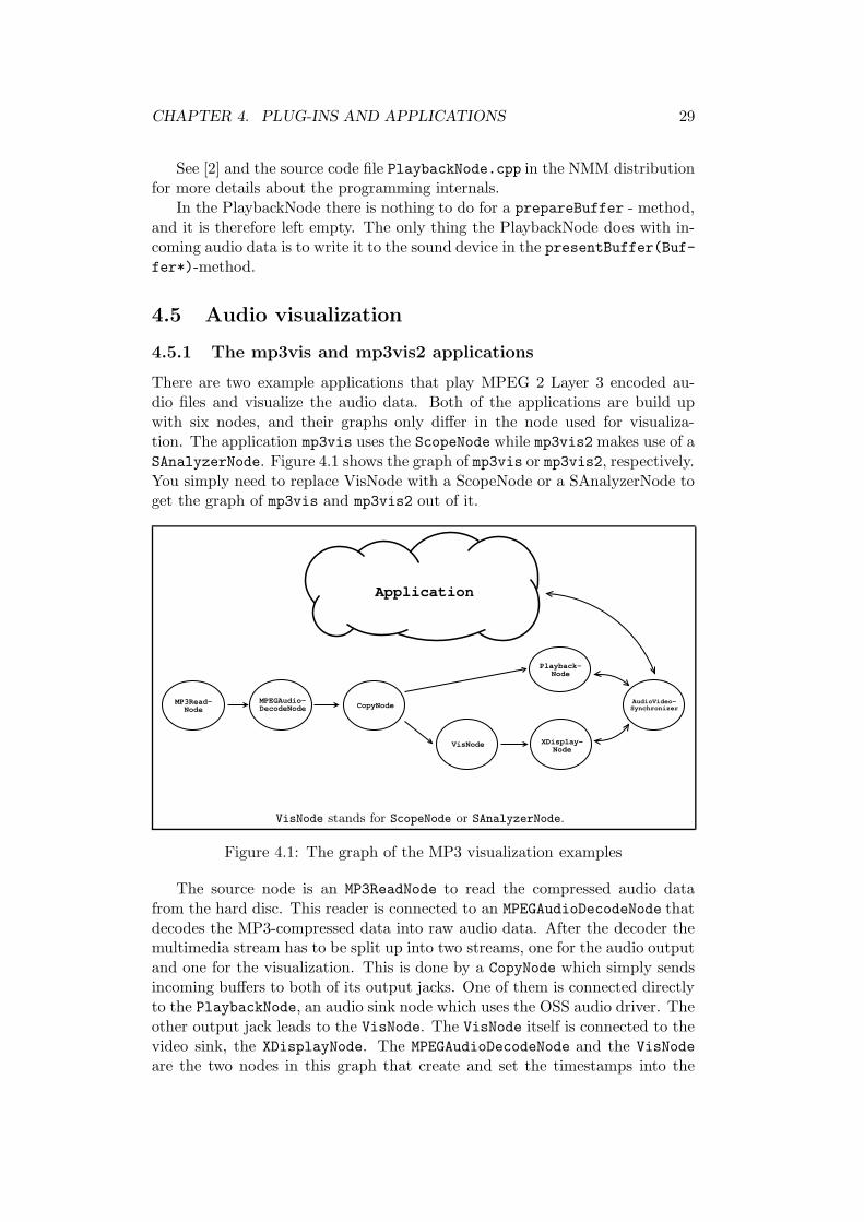
without blur effect . . . and with blur effect
Figure 4.2: Screenshots of mp3vis (ScopeNode)
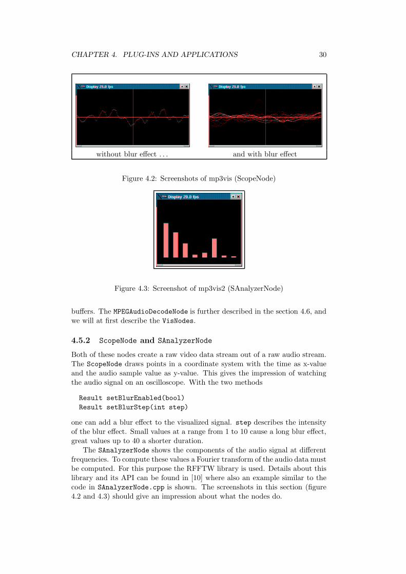
Figure 4.3: Screenshot of mp3vis2 (SAnalyzerNode)
buffers. The MPEGAudioDecodeNode is further described in the section 4.6, andwe will at first describe the VisNodes.
4.5.2 ScopeNode and SAnalyzerNode
Both of these nodes create a raw video data stream out of a raw audio stream.The ScopeNode draws points in a coordinate system with the time as x-valueand the audio sample value as y-value. This gives the impression of watchingthe audio signal on an oscilloscope. With the two methods
Result setBlurEnabled(bool)
Result setBlurStep(int step)
one can add a blur effect to the visualized signal. step describes the intensityof the blur effect. Small values at a range from 1 to 10 cause a long blur effect,great values up to 40 a shorter duration.
The SAnalyzerNode shows the components of the audio signal at differentfrequencies. To compute these values a Fourier transform of the audio data mustbe computed. For this purpose the RFFTW library is used. Details about thislibrary and its API can be found in [10] where also an example similar to thecode in SAnalyzerNode.cpp is shown. The screenshots in this section (figure4.2 and 4.3) should give an impression about what the nodes do.
CHAPTER 4. PLUG-INS AND APPLICATIONS 31
The nodes use a StreamTimer in the CONST RATE-mode to set timestampsto the outgoing buffers.
4.5.3 Synchronization in the application code
We will now take a look at the application source code to understand whatan application programmer has to know about synchronization. At first thesynchronization must be switched on for all sink nodes. Then an AudioVideo-Synchronizer is created and the sinks are registered to it.
XDisplayNode* display = new XDisplayNode(...);
display -> setSynchronized( true );
PlaybackNode* playback = new PlaybackNode(...);
playback -> setSynchronized( true );
AudioVideoSynchronizer* sync = new AudioVideoSynchronizer();
sync -> setVideoSink( display );
sync -> setAudioSink( playback );
These few lines of code suffice in these two examples to get a synchro-nized audio/video presentation. Additionally the two examples offer a pause-functionality which simply uses the two function calls sync -> pause(); andsync -> wakeup();
4.6 MPEG decoding
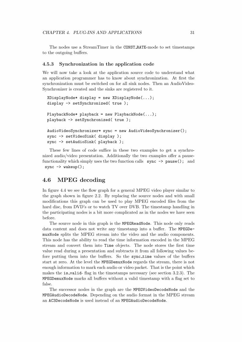
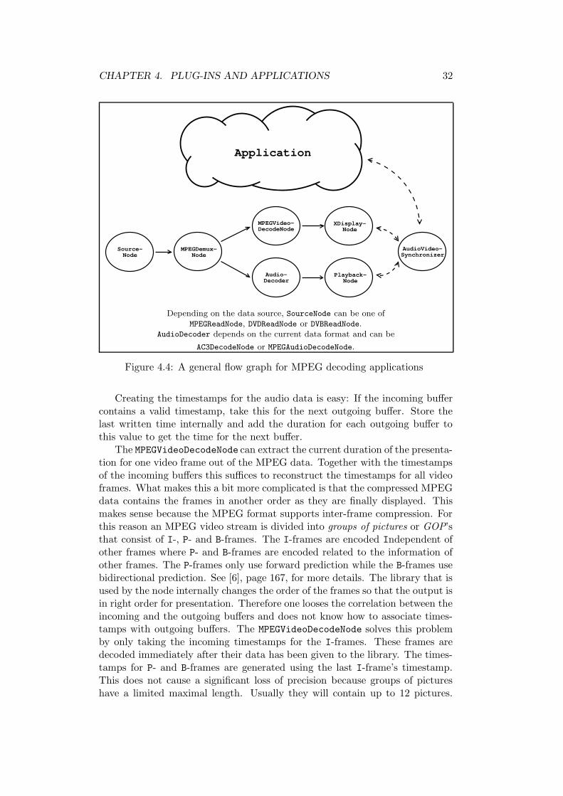
In figure 4.4 we see the flow graph for a general MPEG video player similar tothe graph shown in figure 2.2. By replacing the source nodes and with smallmodifications this graph can be used to play MPEG encoded files from thehard disc, from DVD’s or to watch TV over DVB. The timestamp handling inthe participating nodes is a bit more complicated as in the nodes we have seenbefore.
The source node in this graph is the MPEGReadNode. This node only readsdata content and does not write any timestamp into a buffer. The MPEGDe-
muxNode splits the MPEG stream into the video and the audio components.This node has the ability to read the time information encoded in the MPEGstream and convert them into Time objects. The node stores the first timevalue read during a presentation and subtracts it from all following values be-fore putting them into the buffers. So the sync time values of the buffersstart at zero. At the level the MPEGDemuxNode regards the stream, there is notenough information to mark each audio or video packet. That is the point whichmakes the is valid- flag in the timestamps necessary (see section 3.2.3). TheMPEGDemuxNode marks all buffers without a valid timestamp with a flag set tofalse.
The successor nodes in the graph are the MPEGVideoDecodeNode and theMPEGAudioDecodeNode. Depending on the audio format in the MPEG streaman AC3DecodeNode is used instead of an MPEGAudioDecodeNode.
CHAPTER 4. PLUG-INS AND APPLICATIONS 32
Source-Node
MPEGDemux-Node
XDisplay-Node
Playback-Node
MPEGVideo-DecodeNode
Audio-Decoder
AudioVideo-Synchronizer
Application
Depending on the data source, SourceNode can be one ofMPEGReadNode, DVDReadNode or DVBReadNode.
AudioDecoder depends on the current data format and can be
AC3DecodeNode or MPEGAudioDecodeNode.
Figure 4.4: A general flow graph for MPEG decoding applications
Creating the timestamps for the audio data is easy: If the incoming buffercontains a valid timestamp, take this for the next outgoing buffer. Store thelast written time internally and add the duration for each outgoing buffer tothis value to get the time for the next buffer.
The MPEGVideoDecodeNode can extract the current duration of the presenta-tion for one video frame out of the MPEG data. Together with the timestampsof the incoming buffers this suffices to reconstruct the timestamps for all videoframes. What makes this a bit more complicated is that the compressed MPEGdata contains the frames in another order as they are finally displayed. Thismakes sense because the MPEG format supports inter-frame compression. Forthis reason an MPEG video stream is divided into groups of pictures or GOP’sthat consist of I-, P- and B-frames. The I-frames are encoded Independent ofother frames where P- and B-frames are encoded related to the information ofother frames. The P-frames only use forward prediction while the B-frames usebidirectional prediction. See [6], page 167, for more details. The library that isused by the node internally changes the order of the frames so that the output isin right order for presentation. Therefore one looses the correlation between theincoming and the outgoing buffers and does not know how to associate times-tamps with outgoing buffers. The MPEGVideoDecodeNode solves this problemby only taking the incoming timestamps for the I-frames. These frames aredecoded immediately after their data has been given to the library. The times-tamps for P- and B-frames are generated using the last I-frame’s timestamp.This does not cause a significant loss of precision because groups of pictureshave a limited maximal length. Usually they will contain up to 12 pictures.
CHAPTER 4. PLUG-INS AND APPLICATIONS 33
Then the next group of pictures will start and the next exact timestamp out ofthe original stream will be taken.
Besides this we have already discussed in section 3.4.2 that selecting a newDVD chapter or TV channel makes it necessary to reset all internally storedtime values in the nodes above. This is done when a sync reset-event occurs.
Appendix A
Source Files
There is not enough space here to show the whole source code that has beenimplemented for the practical project. I will only give a list of the source fileswhich can be found in the NMM software distribution1.
The classes that build the underlying architecture are located in a specialdirectory (nmm/base/sync). These files contain:
• nmm/base/sync/Rational.hpp
• nmm/base/sync/Rational.cpp
• nmm/base/sync/Types.hpp
• nmm/base/sync/Types.cpp
• nmm/base/sync/Clock.hpp
• nmm/base/sync/Clock.cpp
• nmm/base/sync/TimedElement.hpp
• nmm/base/sync/TimedElement.cpp
• nmm/base/sync/Controller.hpp
• nmm/base/sync/Controller.cpp
• nmm/base/sync/SinkController.hpp
• nmm/base/sync/SinkController.cpp
• nmm/base/sync/BSinkController.hpp
• nmm/base/sync/BSinkController.cpp
• nmm/base/sync/USinkController.hpp
• nmm/base/sync/USinkController.cpp
1The NMM software is available for download at http://www.networkmultimedia.org.
34
APPENDIX A. SOURCE FILES 35
• nmm/base/sync/GenericSyncSinkNode.hpp
• nmm/base/sync/GenericSyncSinkNode.cpp
• nmm/base/sync/GenericBSyncSinkNode.hpp
• nmm/base/sync/GenericBSyncSinkNode.cpp
• nmm/base/sync/GenericUSyncSinkNode.hpp
• nmm/base/sync/GenericUSyncSinkNode.cpp
• nmm/base/sync/Synchronizer.hpp
• nmm/base/sync/Synchronizer.cpp
• nmm/base/sync/AudioVideoSynchronizer.hpp
• nmm/base/sync/AudioVideoSynchronizer.cpp
I wrote some examples for timestamp handling in plug-in nodes and syn-chronization in application programs (described in chapter 4.5). These includethe following files:
• nmm/plugins/audio/visualization/ScopeNode.hpp
• nmm/plugins/audio/visualization/ScopeNode.cpp
• nmm/plugins/audio/visualization/SAnalyzerNode.hpp
• nmm/plugins/audio/visualization/SAnalyzerNode.cpp
• nmm/examples/mp3dec/mp3vis.cpp
• nmm/examples/mp3dec/mp3vis2.cpp
Besides these, synchronization handling has been added to many of the plug-in nodes that already existed before. Most of the extensions consisted only ofa few lines of additional code. I would only like to mention the sink nodes andespecially the OSS audio sink node because there were significant changes tothe source code (see also chapter 4.4.2). It can be found in the files
• nmm/plugins/audio/PlaybackNode.hpp
• nmm/plugins/audio/PlaybackNode.cpp
List of Figures
1.1 Intra-object synchronization . . . . . . . . . . . . . . . . . . . . 41.2 Inter-object synchronization . . . . . . . . . . . . . . . . . . . . 5
2.1 Nodes and Messages . . . . . . . . . . . . . . . . . . . . . . . . . 72.2 A simple node graph for an MPEG video player . . . . . . . . . 9
3.1 General overview of synchronization components . . . . . . . . . 113.2 The notion of latency . . . . . . . . . . . . . . . . . . . . . . . . 123.3 GenericSyncSinkNode in the NMM class hierarchy . . . . . . . 173.4 The class hierarchy for Controller and its subclasses . . . . . . 193.5 States and state transitions of a Controller . . . . . . . . . . . 213.6 States and state transitions of a Synchronizer . . . . . . . . . . 223.7 Problems with different path lengths . . . . . . . . . . . . . . . . 233.8 Sink nodes, controllers and synchronizer during a sync reset-
event . . . . . . . . . . . . . . . . . . . . . . . . . . . . . . . . . 24
4.1 The graph of the MP3 visualization examples . . . . . . . . . . . 294.2 Screenshots of mp3vis (ScopeNode) . . . . . . . . . . . . . . . . . 304.3 Screenshot of mp3vis2 (SAnalyzerNode) . . . . . . . . . . . . . . 304.4 A general flow graph for MPEG decoding applications . . . . . . 32
36
Bibliography
[1] Network-Integrated Multimedia Middleware (NMM). Project’s homepage:http://www.networkmultimedia.org.
[2] 4Front Technologies. Open Sound System Programmer’s Guide, 2000.http://www.opensound.com.
[3] Be, Inc. The Be Book for BeOS Release 5, 2000.
[4] Patrick Becker, Patrick Cernko, Wolfgang Enderlein, Marc Klein, andMarkus Sand. Design and Development of a Multimedia Home Enter-tainment System for Linux. Universitat des Saarlandes, 2002. Advancedpractical project.
[5] Gordon Blair and Jean-Bernard Stefani. Open Distributed Processing andMultimedia. Addison-Wesley, 1. edition, 1998.
[6] John F. Koegel Buford. Multimedia Systems. ACM Press, 1. edition, 1994.
[7] Steve Howell. OpenML Version 1.0 Final Specification. Khronos Group,2001. http://www.khronos.org/openml.
[8] Keith Jack. Video Demystified. LLH Technology Publisher, 2. edition,1996.
[9] Helmut Kopka. LATEX – Einfuhrung Band 1. Addison-Wesley Verlag, 3.edition, 2000.
[10] Massachusetts Institute of Technology. FFTW Tutorial (for Version 2.1.3),1999. http://www.fftw.org.
[11] Chris Pirazzi. Introduction to UST and UST/MSC. Internet site:http://www.lurkertech.com/lg/time/intro.html.
[12] Ralf Steinmetz. Multimedia-Technologie. Springer-Verlag, 2. edition, 1999.
[13] Ralf Steinmetz and Klara Nahrstedt. Multimedia: Computing, Communi-cations and Applications. Prentice Hall, 1. edition, 1995.
[14] Bjarne Stroustrup. Die C++ Programmiersprache. Addison-Wesley Ver-lag, 4. edition, 2000.
[15] W3C. Synchronized Multimedia Integration Language (SMIL 2.0), 2001.http://www.w3.org/TR/smil20.
37