Embed Size (px)
Citation preview
Anthony Magee, ITSF 2011, Edinburgh
Synchronization in Mobile Backhaul Deployment Topologies & Synchronization Service Tools
© 2011 ADVA Optical Networking. All rights reserved. Confidential. 2 2
Deployment Topologies
Managing Multiple Mobile Operators
LTE Advanced – and beyond…
Agenda
Synchronization as a Service
Service Level Agreement Tools
Courtesy: The Early Learning Centre
Is telling the time accurately ever as simple as child’s play?
© 2011 ADVA Optical Networking. All rights reserved. Confidential. 3 3
Synchronization Deployment Topologies
© 2011 ADVA Optical Networking. All rights reserved. Confidential. 4 4
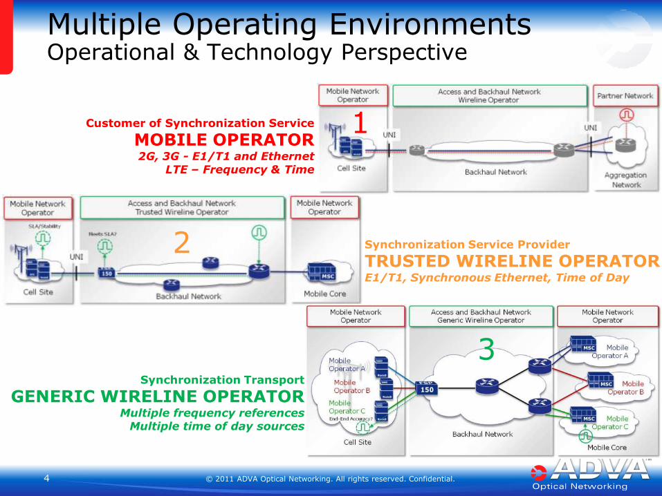
Multiple Operating Environments Operational & Technology Perspective
Customer of Synchronization Service
MOBILE OPERATOR 2G, 3G - E1/T1 and Ethernet
LTE – Frequency & Time
Synchronization Service Provider
TRUSTED WIRELINE OPERATOR E1/T1, Synchronous Ethernet, Time of Day
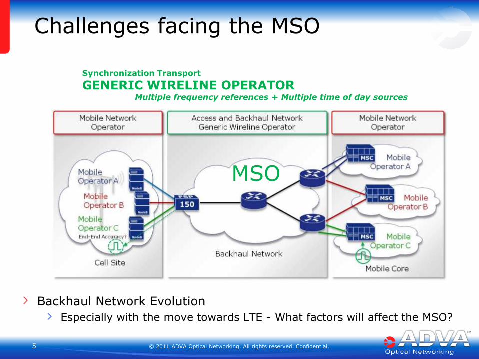
Synchronization Transport
GENERIC WIRELINE OPERATOR Multiple frequency references
Multiple time of day sources
1
2
3
© 2011 ADVA Optical Networking. All rights reserved. Confidential. 5 5
Backhaul Network Evolution
Especially with the move towards LTE - What factors will affect the MSO?
Challenges facing the MSO
Synchronization Transport
GENERIC WIRELINE OPERATOR Multiple frequency references + Multiple time of day sources
MSO
© 2011 ADVA Optical Networking. All rights reserved. Confidential. 6 6
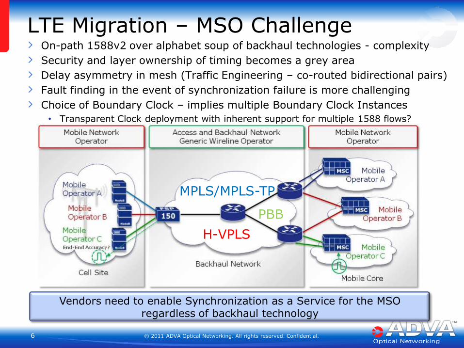
On-path 1588v2 over alphabet soup of backhaul technologies - complexity
Security and layer ownership of timing becomes a grey area
Delay asymmetry in mesh (Traffic Engineering – co-routed bidirectional pairs)
Fault finding in the event of synchronization failure is more challenging
Choice of Boundary Clock – implies multiple Boundary Clock Instances
• Transparent Clock deployment with inherent support for multiple 1588 flows?
LTE Migration – MSO Challenge
MPLS/MPLS-TP
Vendors need to enable Synchronization as a Service for the MSO regardless of backhaul technology
H-VPLS
PBB
© 2011 ADVA Optical Networking. All rights reserved. Confidential. 7 7
Antenna Clusters for MIMO architectures
Base station hotels more likely
Driving change in the backhaul topology
Increased bandwidth to the cell-site
Broadband access in rural areas – Fixed Mobile Convergence
Different traffic patterns – PDV profiles changeable
More stringent time of day alignment – 1us margin to 500ns
Trend will surely be towards increased levels of accuracy
Previous presentations to ITSF have mentioned references to 200ns for location based services
What works for todays requirements may not satisfy tomorrows network…
LTE Advanced
© 2011 ADVA Optical Networking. All rights reserved. Confidential. 8 8
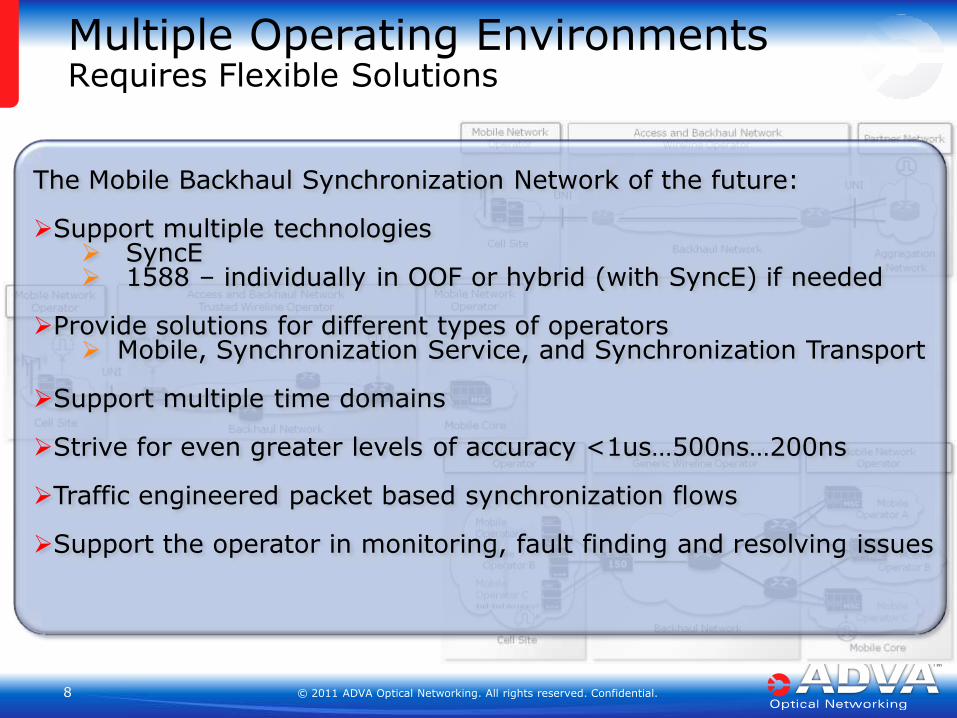
Multiple Operating Environments Requires Flexible Solutions
The Mobile Backhaul Synchronization Network of the future: Support multiple technologies
SyncE 1588 – individually in OOF or hybrid (with SyncE) if needed
Provide solutions for different types of operators Mobile, Synchronization Service, and Synchronization Transport
Support multiple time domains
Strive for even greater levels of accuracy <1us…500ns…200ns
Traffic engineered packet based synchronization flows
Support the operator in monitoring, fault finding and resolving issues
© 2011 ADVA Optical Networking. All rights reserved. Confidential. 9 9
Synchronization as a Service Deployment & Monitoring SLA Tools
© 2011 ADVA Optical Networking. All rights reserved. Confidential. 10 10
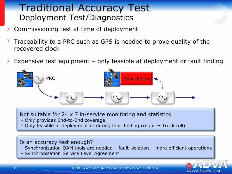
Traditional Accuracy Test Deployment Test/Diagnostics
Commissioning test at time of deployment
Traceability to a PRC such as GPS is needed to prove quality of the recovered clock
Expensive test equipment – only feasible at deployment or fault finding
Not suitable for 24 x 7 in-service monitoring and statistics - Only provides End-to-End coverage - Only feasible at deployment or during fault finding (requires truck roll)
Sync Tester PRC
Is an accuracy test enough? - Synchronization OAM tools are needed – fault isolation – more efficient operations - Synchronization Service Level Agreement
© 2011 ADVA Optical Networking. All rights reserved. Confidential. 11 11
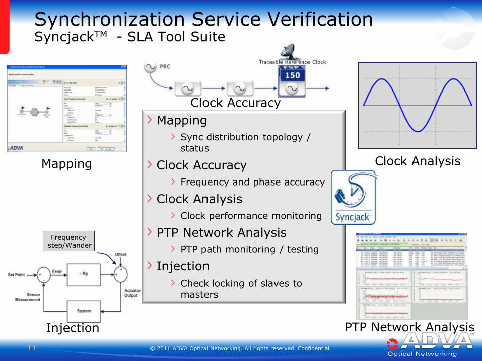
Mapping
Sync distribution topology / status
Clock Accuracy
Frequency and phase accuracy
Clock Analysis
Clock performance monitoring
PTP Network Analysis
PTP path monitoring / testing
Injection
Check locking of slaves to masters
Synchronization Service Verification SyncjackTM - SLA Tool Suite
Clock Accuracy
Mapping
Clock Analysis
PTP Network Analysis
Injection
Frequency step/Wander
© 2011 ADVA Optical Networking. All rights reserved. Confidential. 12 12
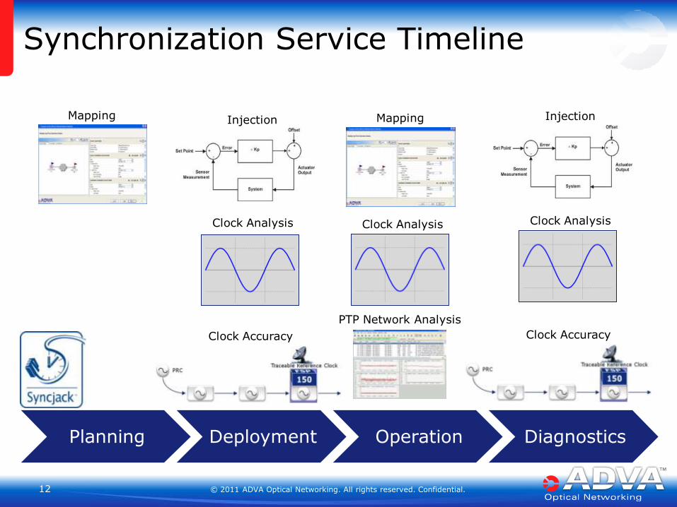
Synchronization Service Timeline
Mapping
Injection
Clock Analysis
Clock Accuracy
Clock Analysis
Mapping
Injection
Clock Analysis
Clock Accuracy
PTP Network Analysis
Planning Deployment Operation Diagnostics
© 2011 ADVA Optical Networking. All rights reserved. Confidential. 13 13
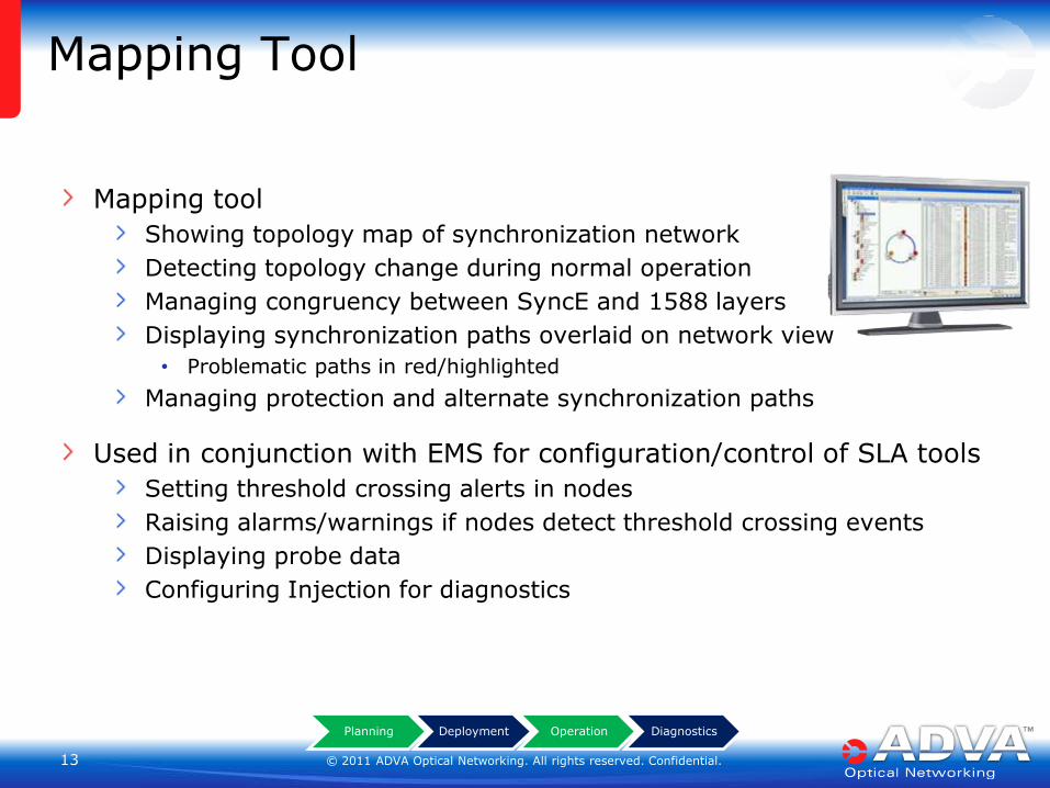
Mapping Tool
Mapping tool
Showing topology map of synchronization network
Detecting topology change during normal operation
Managing congruency between SyncE and 1588 layers
Displaying synchronization paths overlaid on network view
• Problematic paths in red/highlighted
Managing protection and alternate synchronization paths
Used in conjunction with EMS for configuration/control of SLA tools
Setting threshold crossing alerts in nodes
Raising alarms/warnings if nodes detect threshold crossing events
Displaying probe data
Configuring Injection for diagnostics
Planning Deployment Operation Diagnostics
© 2011 ADVA Optical Networking. All rights reserved. Confidential. 14 14
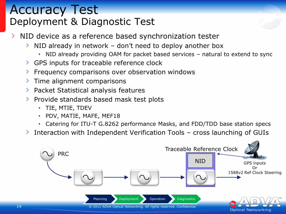
Accuracy Test Deployment & Diagnostic Test
NID device as a reference based synchronization tester
NID already in network – don’t need to deploy another box
• NID already providing OAM for packet based services – natural to extend to sync
GPS inputs for traceable reference clock
Frequency comparisons over observation windows
Time alignment comparisons
Packet Statistical analysis features
Provide standards based mask test plots
• TIE, MTIE, TDEV
• PDV, MATIE, MAFE, MEF18
• Catering for ITU-T G.8262 performance Masks, and FDD/TDD base station specs
Interaction with Independent Verification Tools – cross launching of GUIs
Planning Deployment Operation Diagnostics
PRC Traceable Reference Clock
GPS inputs Or
1588v2 Ref Clock Steering
NID
© 2011 ADVA Optical Networking. All rights reserved. Confidential. 15 15
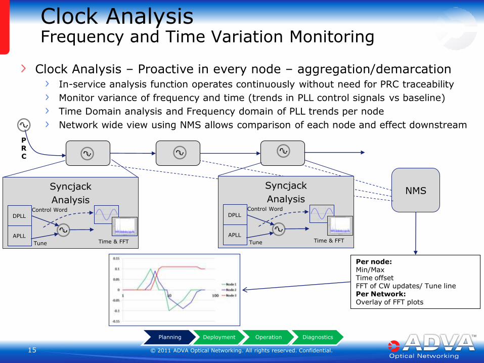
Clock Analysis Frequency and Time Variation Monitoring
PRC
NMS
Per node: Min/Max Time offset FFT of CW updates/ Tune line Per Network: Overlay of FFT plots
Syncjack
Analysis
DPLL
APLL
Control Word
Tune Time & FFT
Syncjack
Analysis
DPLL
APLL
Control Word
Tune Time & FFT
Planning Deployment Operation Diagnostics
Clock Analysis – Proactive in every node – aggregation/demarcation In-service analysis function operates continuously without need for PRC traceability
Monitor variance of frequency and time (trends in PLL control signals vs baseline)
Time Domain analysis and Frequency domain of PLL trends per node
Network wide view using NMS allows comparison of each node and effect downstream
© 2011 ADVA Optical Networking. All rights reserved. Confidential. 16 16
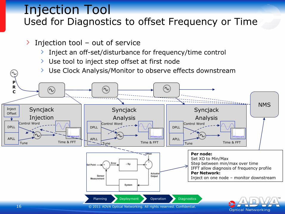
Injection Tool Used for Diagnostics to offset Frequency or Time
PRC
NMS
Per node: Set XO to Min/Max Step between min/max over time IFFT allow diagnosis of frequency profile Per Network: Inject on one node – monitor downstream
Syncjack
Injection
DPLL
APLL
Control Word
Tune
Inject
Offset
Time & FFT
Planning Deployment Operation Diagnostics
Syncjack
Analysis
DPLL
APLL
Control Word
Tune Time & FFT
Syncjack
Analysis
DPLL
APLL
Control Word
Tune Time & FFT
Injection tool – out of service
Inject an off-set/disturbance for frequency/time control
Use tool to inject step offset at first node
Use Clock Analysis/Monitor to observe effects downstream
© 2011 ADVA Optical Networking. All rights reserved. Confidential. 17 17
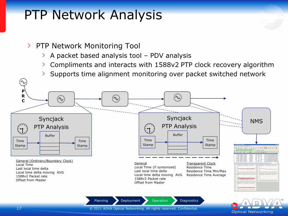
PTP Network Analysis
PTP Network Monitoring Tool
A packet based analysis tool – PDV analysis
Compliments and interacts with 1588v2 PTP clock recovery algorithm
Supports time alignment monitoring over packet switched network
PRC
NMS Syncjack
PTP Analysis
Time
Stamp
Time
Stamp
Buffer
Transparent Clock Residence Time Residence Time Min/Max Residence Time Average
Syncjack
PTP Analysis
Time
Stamp
Time
Stamp
Buffer
General (Ordinary/Boundary Clock) Local Time Last local time delta Local time delta moving AVG 1588v2 Packet rate Offset from Master
General Local Time (if syntonized) Last local time delta Local time delta moving AVG 1588v2 Packet rate
Offset from Master
Planning Deployment Operation Diagnostics
© 2011 ADVA Optical Networking. All rights reserved. Confidential. 18 18
Synchronization SLA Tools in Practice
© 2011 ADVA Optical Networking. All rights reserved. Confidential. 19 19
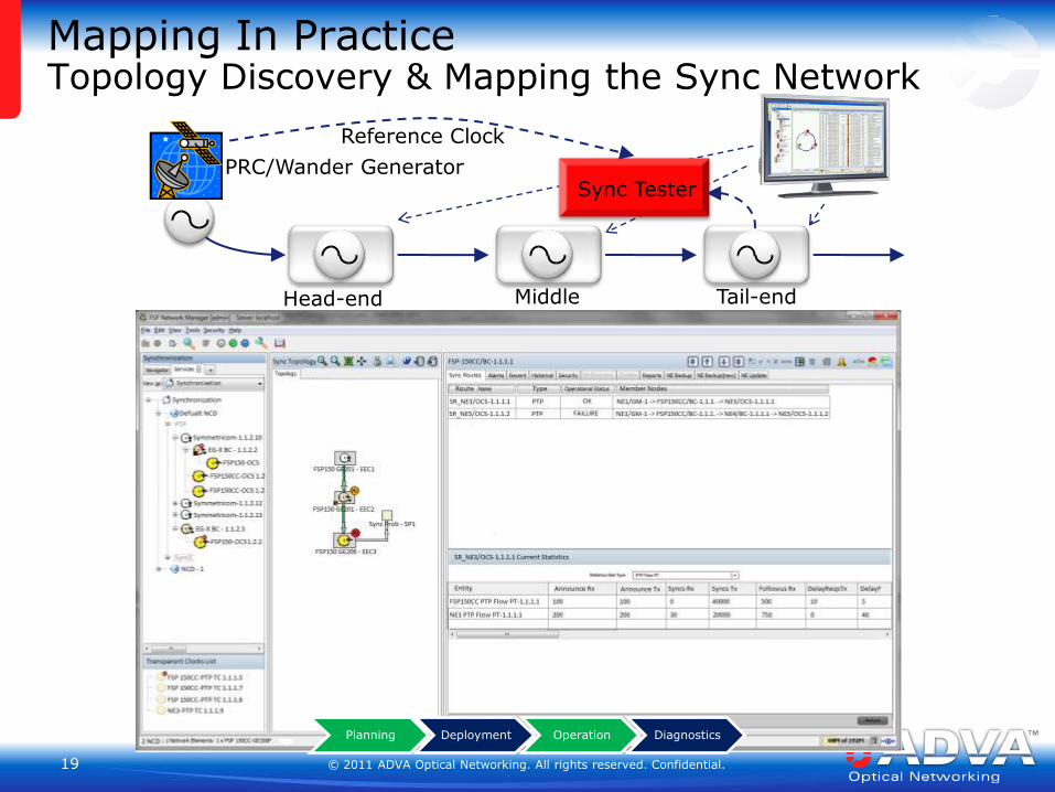
Mapping In Practice Topology Discovery & Mapping the Sync Network
Planning Deployment Operation Diagnostics
Sync Tester PRC/Wander Generator
Reference Clock
Head-end Middle Tail-end
© 2011 ADVA Optical Networking. All rights reserved. Confidential. 20 20
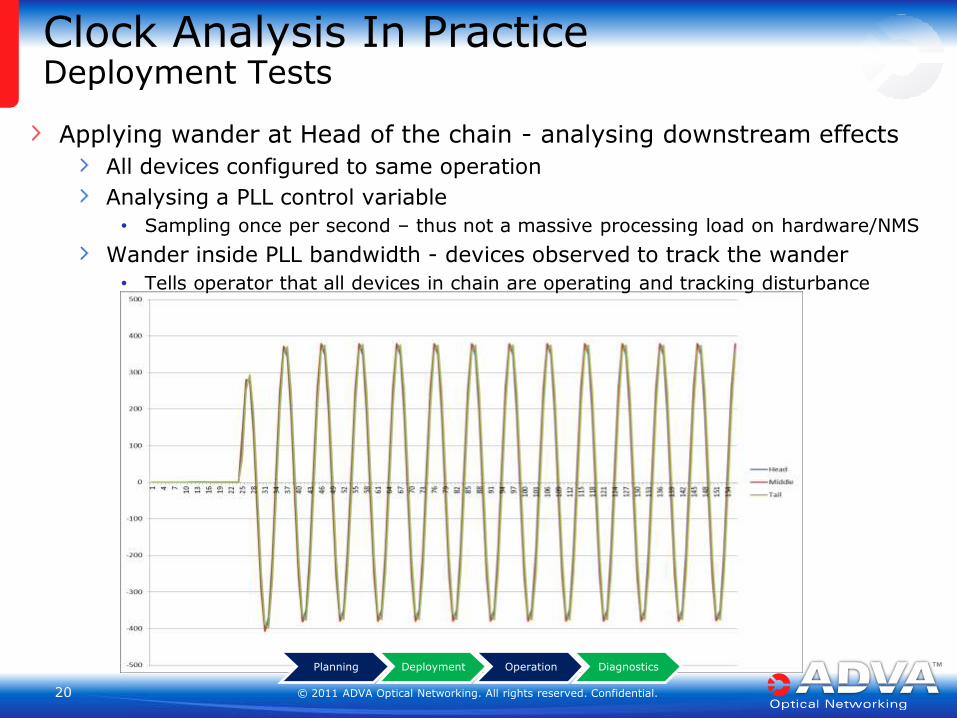
Clock Analysis In Practice Deployment Tests
Applying wander at Head of the chain - analysing downstream effects
All devices configured to same operation
Analysing a PLL control variable
• Sampling once per second – thus not a massive processing load on hardware/NMS
Wander inside PLL bandwidth - devices observed to track the wander
• Tells operator that all devices in chain are operating and tracking disturbance
Planning Deployment Operation Diagnostics
© 2011 ADVA Optical Networking. All rights reserved. Confidential. 21 21
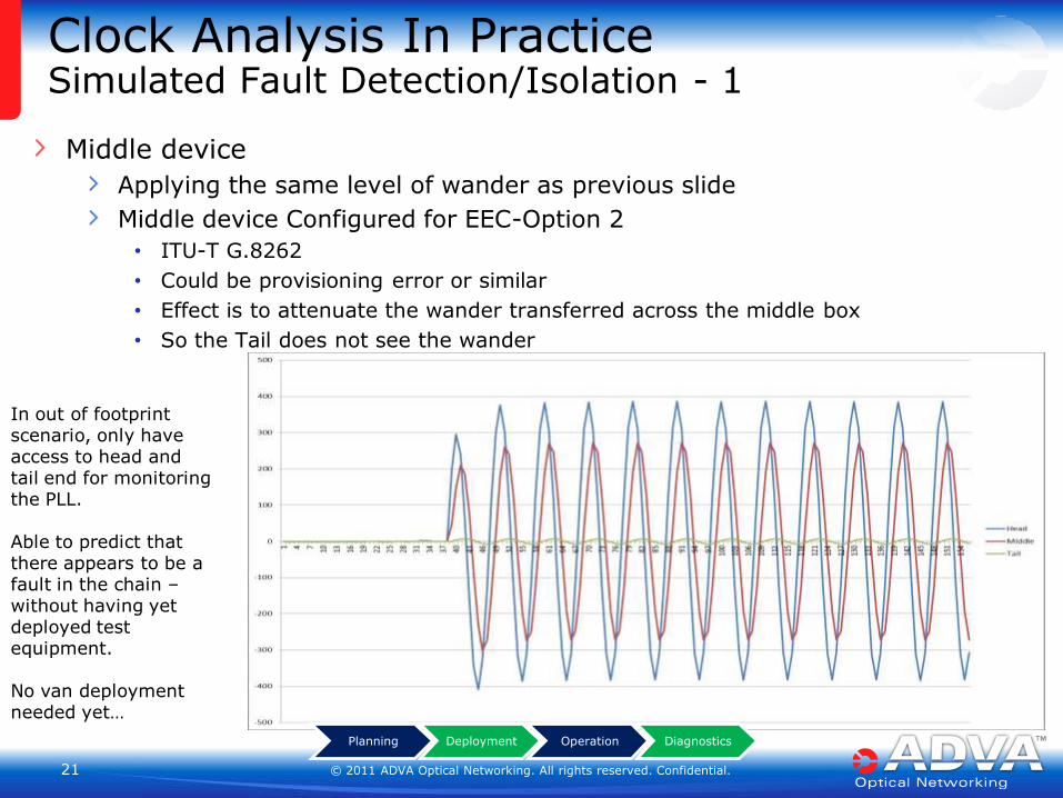
Clock Analysis In Practice Simulated Fault Detection/Isolation - 1
Middle device
Applying the same level of wander as previous slide
Middle device Configured for EEC-Option 2
• ITU-T G.8262
• Could be provisioning error or similar
• Effect is to attenuate the wander transferred across the middle box
• So the Tail does not see the wander
In out of footprint scenario, only have access to head and tail end for monitoring the PLL. Able to predict that there appears to be a fault in the chain – without having yet deployed test equipment. No van deployment needed yet… Planning Deployment Operation Diagnostics
© 2011 ADVA Optical Networking. All rights reserved. Confidential. 22 22
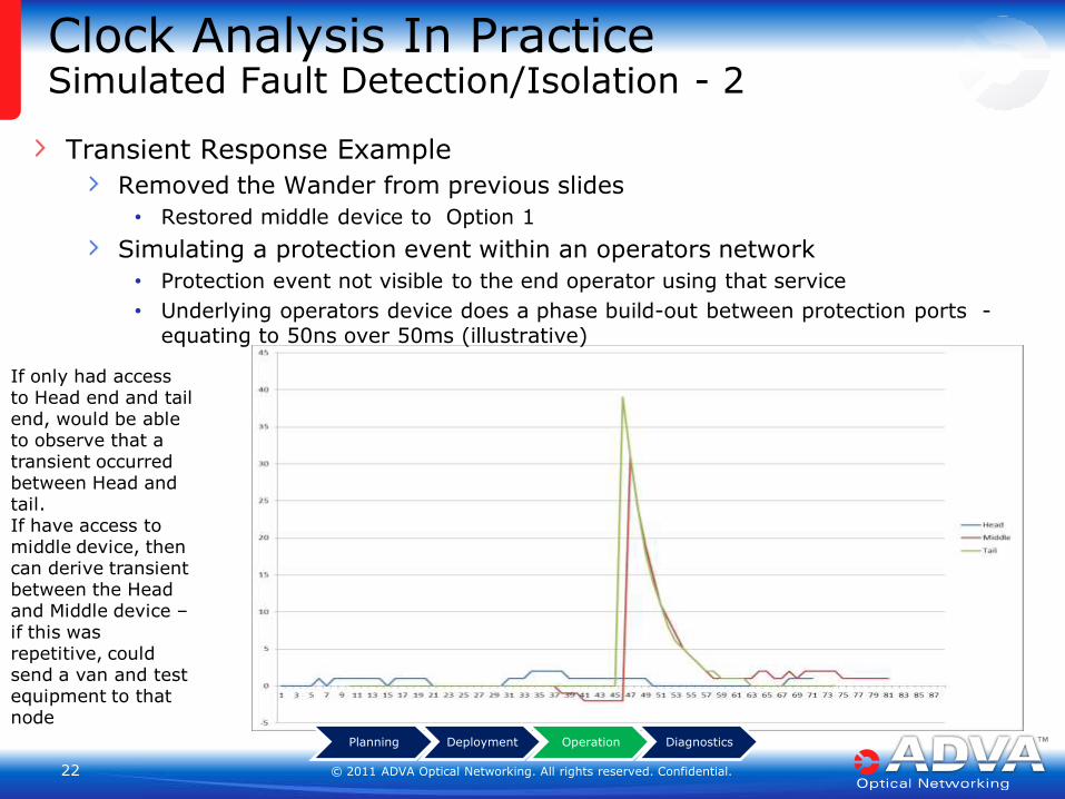
Clock Analysis In Practice Simulated Fault Detection/Isolation - 2
Transient Response Example
Removed the Wander from previous slides
• Restored middle device to Option 1
Simulating a protection event within an operators network
• Protection event not visible to the end operator using that service
• Underlying operators device does a phase build-out between protection ports - equating to 50ns over 50ms (illustrative)
Planning Deployment Operation Diagnostics
If only had access to Head end and tail end, would be able to observe that a transient occurred between Head and tail. If have access to middle device, then can derive transient between the Head and Middle device – if this was repetitive, could send a van and test equipment to that node
© 2011 ADVA Optical Networking. All rights reserved. Confidential. 23 23
Managing Synchronization Networks
Adoption by industry and standards to capture a baseline feature set Goal: With the right tools, managing the Sync SLA should be as simple as…
child’s play!
Tools and Procedures
Clock Analysis & Accuracy
Network View
Identify fault locations, speed up
fault resolution
Visibility within network - not
just at the PRC and Cell-site
Monitor in operation
performance of individual nodes. Historical records
Keep the customer informed Maintain customer loyalty
Reduce OPEX $$$

Anthony Magee ADVA Optical Networking
Thank you – Any Questions
IMPORTANT NOTICE
The content of this presentation is strictly confidential. ADVA Optical Networking is the exclusive owner or licensee of the content, material, and information in this presentation. Any reproduction, publication or reprint, in whole or in part, is strictly prohibited.
The information in this presentation may not be accurate, complete or up to date, and is provided without warranties or representations of any kind, either express or implied. ADVA Optical Networking shall not be responsible for and disclaims any liability for any loss or damages, including without limitation, direct, indirect, incidental, consequential and special damages, alleged to have been caused by or in connection with using and/or relying on the information contained in this presentation.
Copyright © for the entire content of this presentation: ADVA Optical Networking.