Embed Size (px)
Citation preview
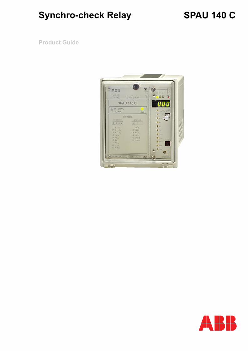
Synchro-check Relay
Product Guide
SPAU 140 C

Synchro-check Relay
Product Guide
SPAU 140 C1MRS750421-MBG
Issued: April 1999Status: Updated Version: C/25.04.2006Data subject to change without notice
3
Features • Two identical operation stages allowing the closing conditions of two separate circuit breakers to be checked
• Synchro-check function available for both operation stages
• Voltage-check function available for both operation stages
• Two different operation modes: continuous mode and command mode operation
• Numerical display of setting values, mea-sured values and values recorded on relay operation
• Continuous auto-diagnostic self-supervi-sion of both relay hardware and software
• Serial interface for connecting the relay to the SPA bus and higher-level host systems
• Powerful software support for parameter-ization of the relay, for reading measured and recorded values, events, etc., and for storing readings
• CE marking according to the EC directive for EMC
Application The numerical synchro-check relay type SPAU 140 C is a voltage measuring relay designed to be used when two power systems are to be connected together.
The synchro-check relay SPAU 140 C can be used for both synchro-check functions and voltage-check functions. The synchro-check function is used when two separate networks
or two electrically interconnected network sections are to be connected together. The voltage-check function is used when a dis-connected bus/line is to be connected to an energized section of a network. The synchro-check function allows circuit breaker closing only if the voltages on both sides of the cir-cuit breaker fulfill the preset conditions as to magnitude, phase and frequency difference.
Synchro-check Relay
Product Guide
SPAU 140 C1MRS750421-MBG
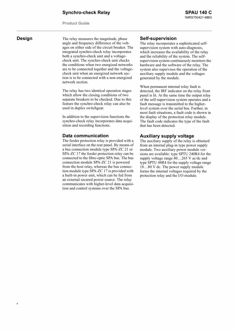
Design The relay measures the magnitude, phase angle and frequency difference of the volt-ages on either side of the circuit breaker. The integrated synchro-check relay incorporates both a synchro-check unit and a voltage-check unit. The synchro-check unit checks the conditions when two energized networks are to be connected together and the voltage-check unit when an energized network sec-tion is to be connected with a non-energized network section.
The relay has two identical operation stages which allow the closing conditions of two separate breakers to be checked. Due to this feature the synchro-check relay can also be used in duplex switchgear.
In addition to the supervision functions the synchro-check relay incorporates data acqui-sition and recording functions.
Data communicationThe feeder protection relay is provided with a serial interface on the rear panel. By means of a bus connection module type SPA-ZC 21 or SPA-ZC 17 the feeder protection relay can be connected to the fibre-optic SPA bus. The bus connection module SPA-ZC 21 is powered from the host relay, whereas the bus connec-tion module type SPA-ZC 17 is provided with a built-in power unit, which can be fed from an external secured power source. The relay communicates with higher-level data acquisi-tion and control systems over the SPA bus.
Self-supervisionThe relay incorporates a sophisticated self-supervision system with auto-diagnosis, which increases the availability of the relay and the reliability of the system. The self-supervision system continuously monitors the hardware and the software of the relay. The system also supervises the operation of the auxiliary supply module and the voltages generated by the module.
When permanent internal relay fault is detected, the IRF indicator on the relay front panel is lit. At the same time the output relay of the self-supervision system operates and a fault message is transmitted to the higher-level system over the serial bus. Further, in most fault situations, a fault code is shown in the display of the protection relay module. The fault code indicates the type of the fault that has been detected.
Auxiliary supply voltageThe auxiliary supply of the relay is obtained from an internal plug-in type power supply module. Two auxiliary power module ver-sions are available: type SPTU 240R4 for the supply voltage range 80…265 V ac/dc and type SPTU 48R4 for the supply voltage range 18…80 V dc. The power supply module forms the internal voltages required by the protection relay and the I/O module.
4
Synchro-check Relay
Product Guide
SPAU 140 C1MRS750421-MBG
5
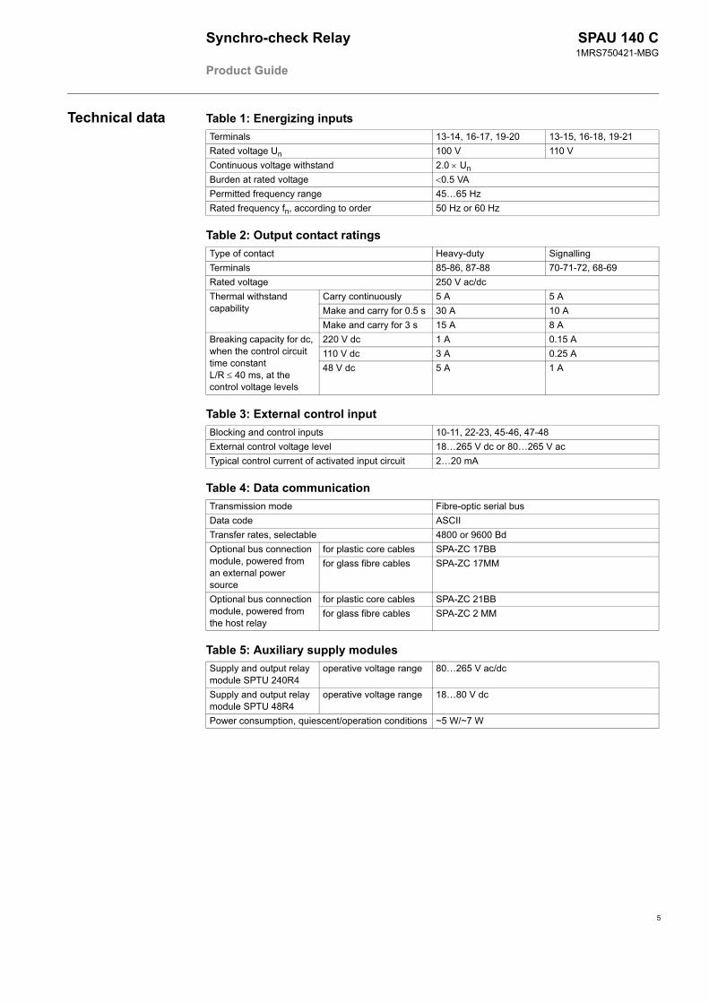
Technical data Table 1: Energizing inputsTerminals 13-14, 16-17, 19-20 13-15, 16-18, 19-21Rated voltage Un 100 V 110 VContinuous voltage withstand 2.0 × UnBurden at rated voltage <0.5 VAPermitted frequency range 45…65 HzRated frequency fn, according to order 50 Hz or 60 Hz
Table 2: Output contact ratingsType of contact Heavy-duty SignallingTerminals 85-86, 87-88 70-71-72, 68-69Rated voltage 250 V ac/dcThermal withstand capability
Carry continuously 5 A 5 AMake and carry for 0.5 s 30 A 10 AMake and carry for 3 s 15 A 8 A
Breaking capacity for dc, when the control circuit time constant L/R ≤ 40 ms, at the control voltage levels
220 V dc 1 A 0.15 A110 V dc 3 A 0.25 A48 V dc 5 A 1 A
Table 3: External control inputBlocking and control inputs 10-11, 22-23, 45-46, 47-48External control voltage level 18…265 V dc or 80…265 V acTypical control current of activated input circuit 2…20 mA
Table 4: Data communicationTransmission mode Fibre-optic serial busData code ASCIITransfer rates, selectable 4800 or 9600 BdOptional bus connection module, powered from an external power source
for plastic core cables SPA-ZC 17BBfor glass fibre cables SPA-ZC 17MM
Optional bus connection module, powered from the host relay
for plastic core cables SPA-ZC 21BBfor glass fibre cables SPA-ZC 2 MM
Table 5: Auxiliary supply modulesSupply and output relay module SPTU 240R4
operative voltage range 80…265 V ac/dc
Supply and output relay module SPTU 48R4
operative voltage range 18…80 V dc
Power consumption, quiescent/operation conditions ~5 W/~7 W
Synchro-check Relay
Product Guide
SPAU 140 C1MRS750421-MBG
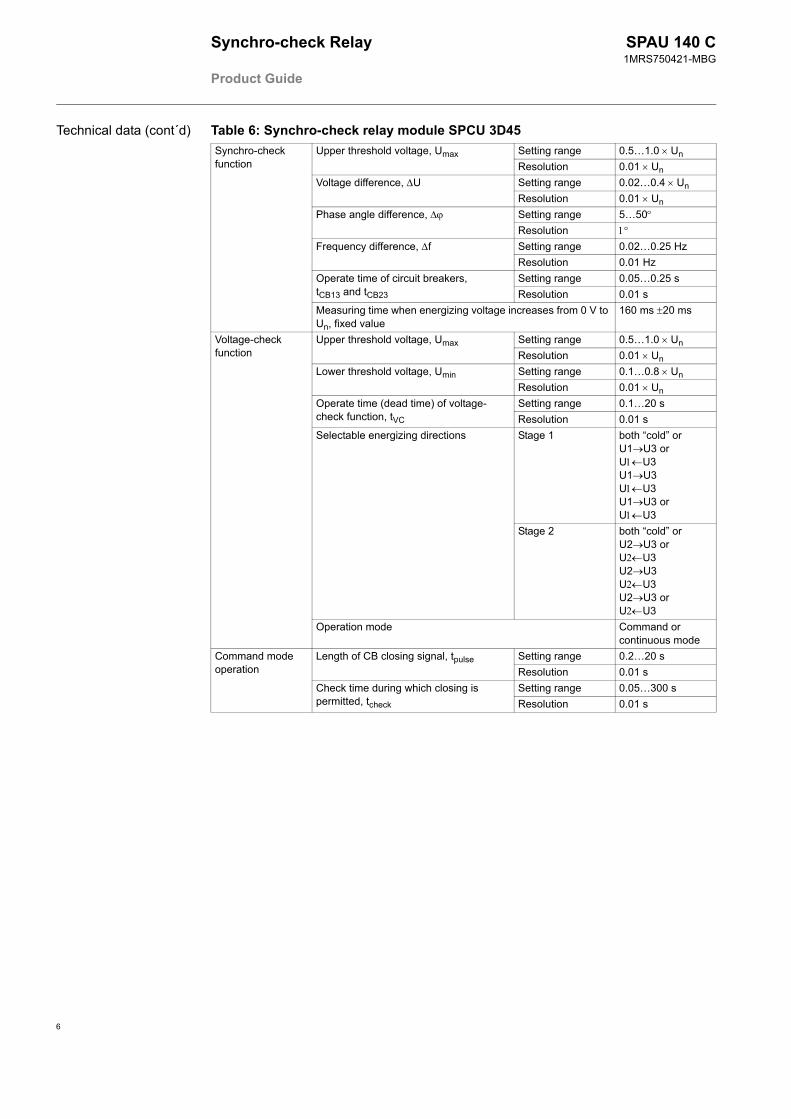
Table 6: Synchro-check relay module SPCU 3D45Synchro-check function
Upper threshold voltage, Umax Setting range 0.5…1.0 × UnResolution 0.01 × Un
Voltage difference, ∆U Setting range 0.02…0.4 × UnResolution 0.01 × Un
Phase angle difference, ∆ϕ Setting range 5…50°Resolution 1°
Frequency difference, ∆f Setting range 0.02…0.25 HzResolution 0.01 Hz
Operate time of circuit breakers,tCB13 and tCB23
Setting range 0.05…0.25 sResolution 0.01 s
Measuring time when energizing voltage increases from 0 V to Un, fixed value
160 ms ±20 ms
Voltage-check function
Upper threshold voltage, Umax Setting range 0.5…1.0 × UnResolution 0.01 × Un
Lower threshold voltage, Umin Setting range 0.1…0.8 × UnResolution 0.01 × Un
Operate time (dead time) of voltage-check function, tVC
Setting range 0.1…20 sResolution 0.01 s
Selectable energizing directions Stage 1 both “cold” orU1→U3 orU1←U3U1→U3U1←U3U1→U3 orU1←U3
Stage 2 both “cold” orU2→U3 orU2←U3U2→U3U2←U3U2→U3 orU2←U3
Operation mode Command or continuous mode
Command mode operation
Length of CB closing signal, tpulse Setting range 0.2…20 sResolution 0.01 s
Check time during which closing is permitted, tcheck
Setting range 0.05…300 sResolution 0.01 s
Technical data (cont´d)
6
Synchro-check Relay
Product Guide
SPAU 140 C1MRS750421-MBG
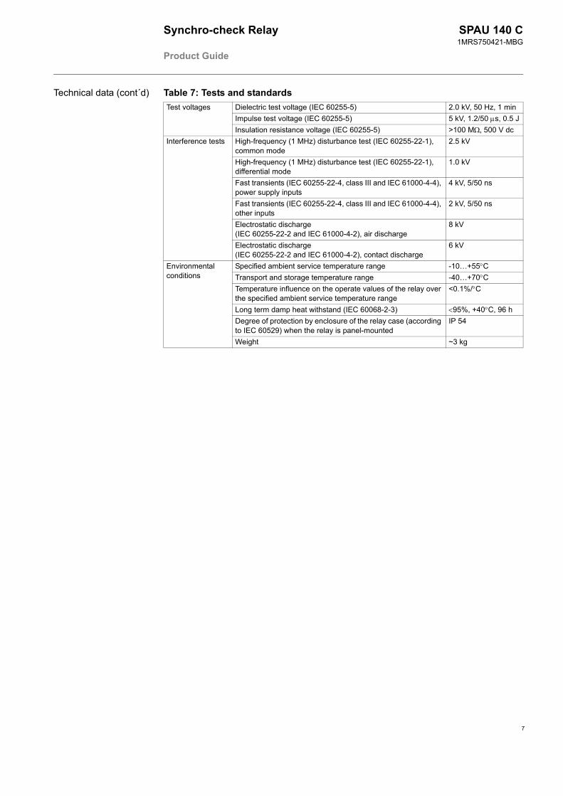
Table 7: Tests and standardsTest voltages Dielectric test voltage (IEC 60255-5) 2.0 kV, 50 Hz, 1 min
Impulse test voltage (IEC 60255-5) 5 kV, 1.2/50 µs, 0.5 JInsulation resistance voltage (IEC 60255-5) >100 MΩ, 500 V dc
Interference tests High-frequency (1 MHz) disturbance test (IEC 60255-22-1), common mode
2.5 kV
High-frequency (1 MHz) disturbance test (IEC 60255-22-1), differential mode
1.0 kV
Fast transients (IEC 60255-22-4, class III and IEC 61000-4-4), power supply inputs
4 kV, 5/50 ns
Fast transients (IEC 60255-22-4, class III and IEC 61000-4-4), other inputs
2 kV, 5/50 ns
Electrostatic discharge(IEC 60255-22-2 and IEC 61000-4-2), air discharge
8 kV
Electrostatic discharge(IEC 60255-22-2 and IEC 61000-4-2), contact discharge
6 kV
Environmental conditions
Specified ambient service temperature range -10…+55°CTransport and storage temperature range -40…+70°CTemperature influence on the operate values of the relay over the specified ambient service temperature range
<0.1%/°C
Long term damp heat withstand (IEC 60068-2-3) <95%, +40°C, 96 hDegree of protection by enclosure of the relay case (according to IEC 60529) when the relay is panel-mounted
IP 54
Weight ~3 kg
Technical data (cont´d)
7
Synchro-check Relay
Product Guide
SPAU 140 C1MRS750421-MBG
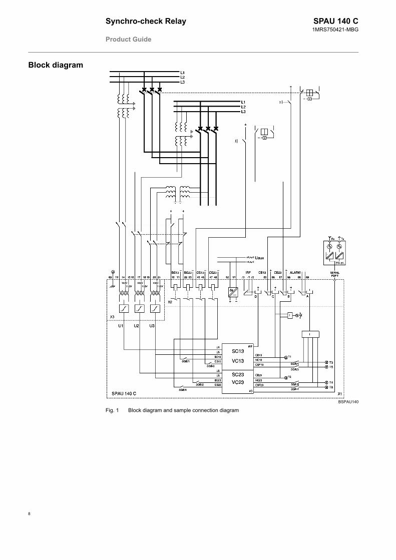
Block diagram
BSPAU140
Fig. 1 Block diagram and sample connection diagram
8
Synchro-check Relay
Product Guide
SPAU 140 C1MRS750421-MBG
9
Mounting and dimensions
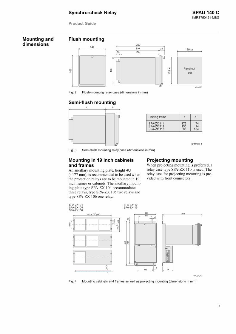
Flush mounting
Fig. 2 Flush-mounting relay case (dimensions in mm)
Panel cut-
out
129 ±1
139
±1
dim100
142
162
136
30
34
250
186
216
Semi-flush mounting
Fig. 3 Semi-flush mounting relay case (dimensions in mm)
Raising frame
SPA-ZX 111SPA-ZX 112SPA-ZX 113
176136 96
74114154
a b
a b
Mounting in 19 inch cabinets and framesAn ancillary mounting plate, height 4U (~177 mm), is recommended to be used when the protection relays are to be mounted in 19 inch frames or cabinets. The ancillary mount-ing plate type SPA-ZX 104 accommodates three relays, type SPA-ZX 105 two relays and type SPA-ZX 106 one relay.
Projecting mountingWhen projecting mounting is preferred, a relay case type SPA-ZX 110 is used. The relay case for projecting mounting is pro-vided with front connectors.
Fig. 4 Mounting cabinets and frames as well as projecting mounting (dimensions in mm)
21,5
482,6 –0 (19")
101,
6 7
+0,4
+0,
417
7 –0
(4
U)
263
986
115
292
312
10
115158
ø6
Synchro-check Relay
Product Guide
SPAU 140 C1MRS750421-MBG
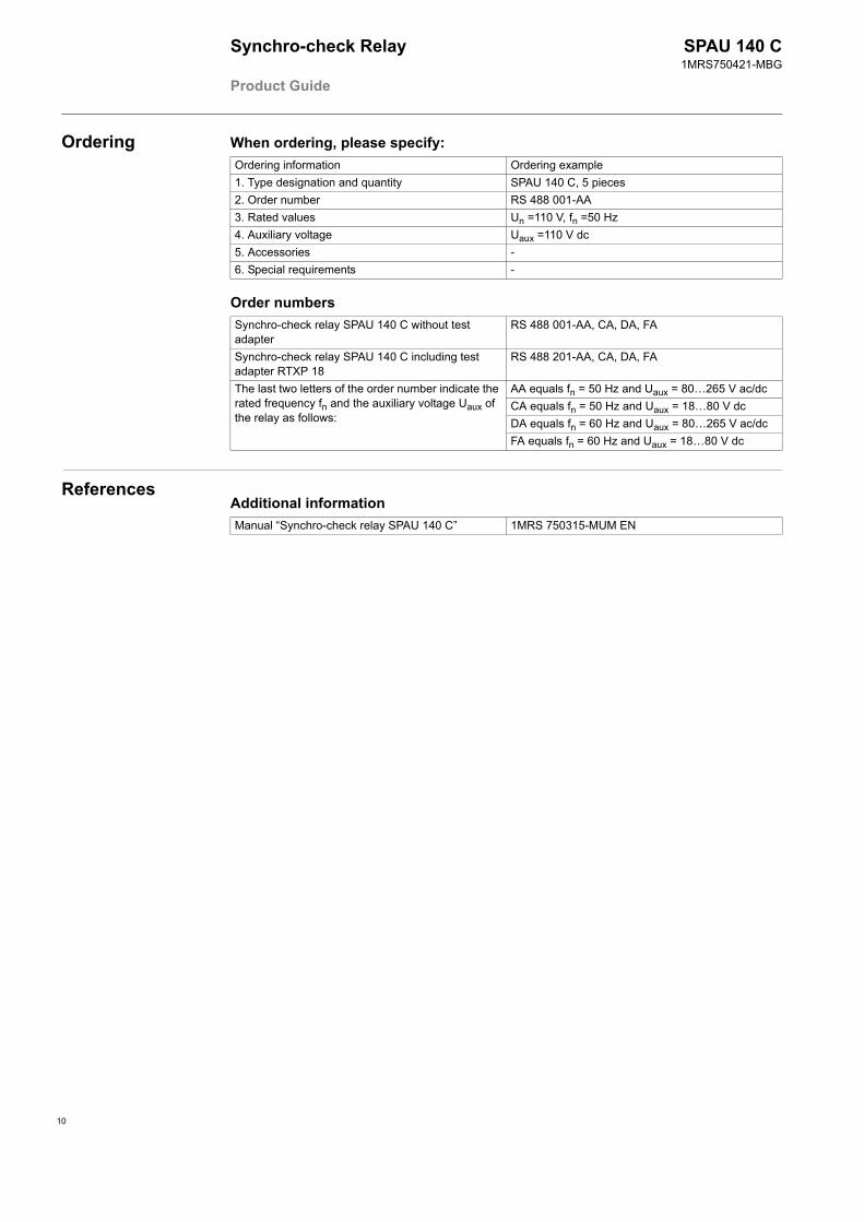
Ordering When ordering, please specify:Ordering information Ordering example1. Type designation and quantity SPAU 140 C, 5 pieces2. Order number RS 488 001-AA3. Rated values Un =110 V, fn =50 Hz4. Auxiliary voltage Uaux =110 V dc5. Accessories -6. Special requirements -
Order numbersSynchro-check relay SPAU 140 C without test adapter
RS 488 001-AA, CA, DA, FA
Synchro-check relay SPAU 140 C including test adapter RTXP 18
RS 488 201-AA, CA, DA, FA
The last two letters of the order number indicate the rated frequency fn and the auxiliary voltage Uaux of the relay as follows:
AA equals fn = 50 Hz and Uaux = 80…265 V ac/dcCA equals fn = 50 Hz and Uaux = 18…80 V dcDA equals fn = 60 Hz and Uaux = 80…265 V ac/dcFA equals fn = 60 Hz and Uaux = 18…80 V dc
ReferencesAdditional informationManual “Synchro-check relay SPAU 140 C” 1MRS 750315-MUM EN
10


ABB OyDistribution AutomationP.O. Box 699 FI-65101 Vaasa, FINLANDTel +358 10 22 11Fax +358 10 224 1094www.abb.com/substationautomation