Embed Size (px)
Citation preview
Symmetry of Crystals
G. Heger
This document has been published in
Thomas Brückel, Gernot Heger, Dieter Richter, Georg Roth and Reiner Zorn (Eds.):Lectures of the JCNS Laboratory Course held at Forschungszentrum Jülich and theresearch reactor FRM II of TU MunichIn cooperation with RWTH Aachen and University of MünsterSchriften des Forschungszentrums Jülich / Reihe Schlüsseltechnologien / Key Tech-nologies, Vol. 39JCNS, RWTH Aachen, University of MünsterForschungszentrum Jülich GmbH, 52425 Jülich, Germany, 2012ISBN: 978-3-89336-789-4All rights reserved.

________________________
Lecture Notes of the JCNS Laboratory Course Neutron Scattering (Forschungszentrum Jülich, 2012, all rights reserved)
3 Symmetry of Crystals
G. Heger RWTH Aachen
Contents
3.1 ............................................................................................2 Introduction
3.2 ........................................................................................2 Crystal lattices
3.3 ...................................................4 Crystallographic coordinate systems
3.4 ......6 Crystallographic symmetry operations and symmetry elements
3.5 .............................10 Crystallographic point groups and space groups
3.6 ..................................................................................................13
Example of the crystal structure description of YBa Cu O using the ITA
2 3 7-
Exercises ..........................................................................................................18

3.2 G. Heger
3.1 Introduction The term “crystal” comes from the Greek κρύσταλλοςwhich was first used as description of ice and later on - more general - of transparent minerals with regular morphology (regular crystal faces and edges).
Fig. 3.1: Example: rock crystal – quartz (SiO2), mineral from the Gotthard-Massif.
Matter is usually classified into three states: gaseous – liquid – solid. Crystals are representatives of the solid state. Crystalline solids are thermodynamically stable in contrast to glasses and are characterised by a regular three-dimensional periodic arrangement of atoms (ions, molecules) in space.
3.2 Crystal lattices The three-dimensional periodicity of crystals can be represented by the so-called crystal lattice. The repeat unit in form of a parallelepiped - known as the unit cell – is defined by 3 non-linear basis vectors a1, a2, and a3, whose directions form the reference axes X, Y, and Z of the corresponding right-handed crystallographic coordination system. The 6 lattice parameters are given as the lengths of the basis vectors a = a1, b = a2, c = a3 and the angles between the basis vectors: angle (a1,a2) = , angle (a2,a3) = , angle (a3,a1) = . The faces of the unit cell are named as face (a1,a2) = C, face (a2,a3) = A, face (a3,a1) = B.
If the vertices of all repeat units (unit cells) are replaced by points, there results the crystal lattice in the form of a point lattice. Each lattice point is given by a vector a = ua1+va2+wa3, with u, v, w being integers. As a symmetry operation of parallel displacement, a – also known as translation vector – maps the atomic arrangement of the crystal (crystal structure) onto itself.

Symmetry of Crystals 3.3
Fig. 3.2: Notation for a unit cell and a point lattice.
A lattice point is named “uvw”, according to the coefficients (integers) of the translation vector a = ua1+va2+wa3 from the origin to the lattice point. A lattice direction - given by the symbol [uvw] - is defined by the direction of the corresponding translation vector.
A plane passing through three lattice points is known as a lattice plane. Since all lattice points are equivalent (by translation symmetry) there will be infinitely many parallel planes passing through all the other points of the lattice. Such a set of equally spaced planes is known as a set of lattice planes. If the first plane from the origin of a set of lattice planes makes intercepts a/h, b/k, c/l on the X, Y, Z axes, respectively, where h, k, l are integers, then the Miller indices of this set of lattice planes are (hkl), the three factors h, k, l being enclosed in parentheses.
The equation of lattice planes can be written in intercept form as
(hx/a) + (ky/b) + (lz/c) = n, (3.1)
where n is an integer. If n = 0 the lattice plane passes through the origin; if n = 1 the plane makes intercepts a/h, b/k, c/l on the X, Y, Z axes respectively; if n = 2 the intercepts are 2a/h, 2b/k, 2c/l; and so on.
The line of intersection of any two non-parallel lattice planes is a row of lattice-points common to both planes. This lattice point row defines a lattice direction [uvw] which is known as zone axis. All lattice planes intersecting in a common lattice-point row are said to lie in the same zone. The condition for lattice planes to be parallel to a lattice vector a = ua1+va2+wa3 is the zone equation
uh + vk + wl = 0 (3.2)
The zone axis symbol [uvw] for the zone containing the two planes (h1k1l1) and (h2k2l2) is obtained by solving the simultaneous equations uh1 + vk1 + wl1 = 0 and uh2 + vk2 + wl2 = 0,
[ uvw] = [k1l2-k2l1, l1h2-l2h1, h1k2-h2k1] (3.3)

3.4 G. Heger
3.3 Crystallographic coordinate systems The description of a crystal structure consists first of the choice of a unit cell as smallest repeat unit of the crystal with its basis vectors. In this way a crystal-specific coordinate system is defined which is used to localize all the atoms in the unit cell. Whereas in physics and chemistry usually Cartesian coordinate systems are used, in crystallography quite different systems are applied. The conventional crystallographic coordinate systems are based on the symmetry of the crystals. In three dimensions there exist 7 different crystal systems and hence 7 crystallographic coordinate systems:
a = b = c; ===90° four triads – 3 or 3
(‖space diagonals of cube) cubic
a = b c; ==90°, =120° one hexad – 6 or 6 (‖Z) hexagonal
a = b c; ==90°, =120° one triad – 3 or 3 (‖Z) trigonal
(hexagonal cell)
a = b c; ===90° one tetrad – 4 or 4 (‖Z) tetragonal
a b c; ===90° three mutually perpendicular diads
– 2 or m (‖X, Y and Z) orthorhombic
a b c; ==90°, >90° one diad – 2 or m (‖Y) monoclinic
(unique axis b)
a b c; 1 or 1 triclinic
conventional unit cell minimum symmetry system name
The choice of the origin of the coordinate system is free in principle, but for convenience it is usually chosen in a centre of symmetry (inversion centre), if present, otherwise in a point of high site symmetry of the space group.
In order to complete the symmetry conventions of the coordinate systems it is necessary to add to the 7 so-called primitive unit cells of the crystal systems (primitive lattice types with only one lattice point per unit cell) 7 centred unit cells with two, three or four lattice points per unit cell (centred lattice types). These centred unit cells are consequently two, three or four times larger than the smallest repeat units of the crystals. The resulting 14 Bravais lattice types with their centring conditions are collected in figure 3.3.
Symmetry of Crystals 3.5
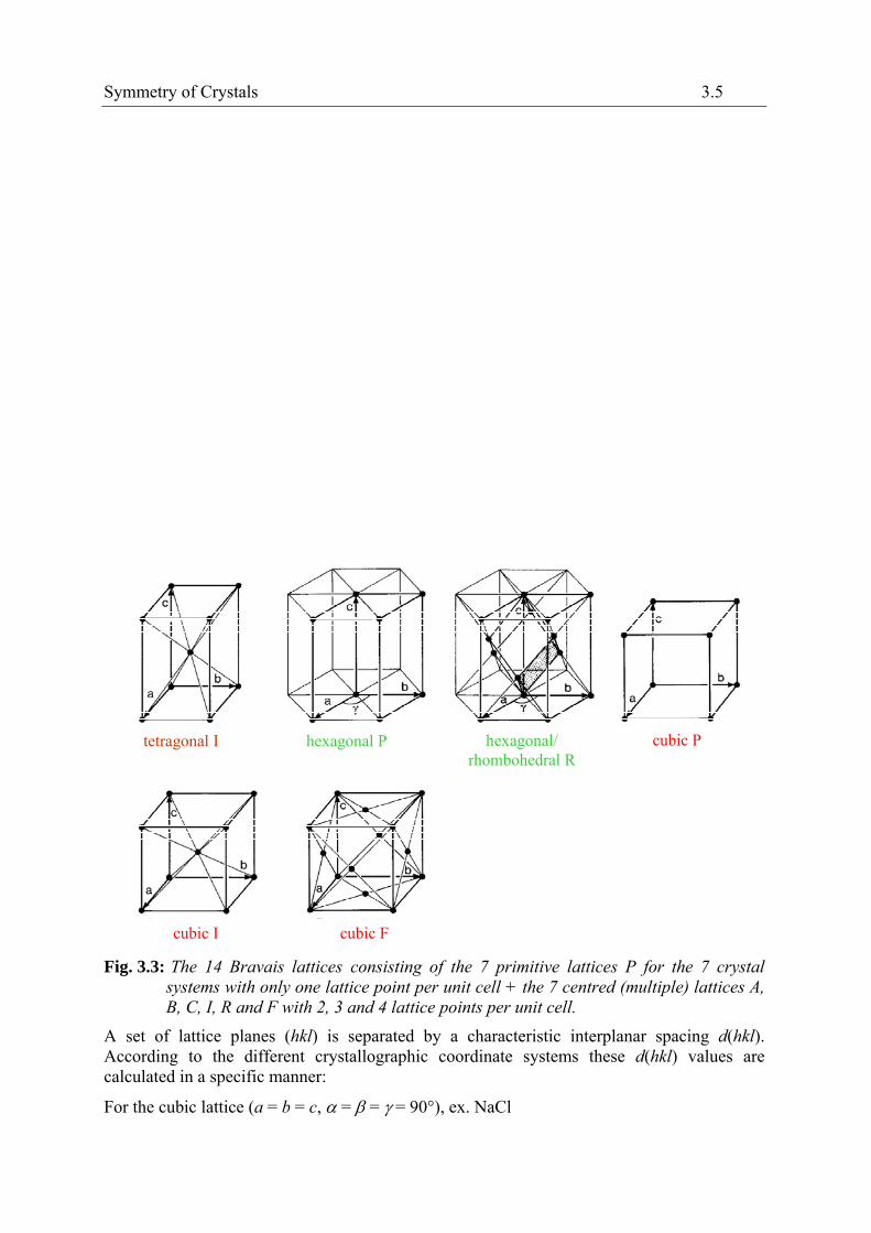
Fig. 3.3: The 14 Bravais lattices consisting of the 7 primitive lattices P for the 7 crystal systems with only one lattice point per unit cell + the 7 centred (multiple) lattices A, B, C, I, R and F with 2, 3 and 4 lattice points per unit cell.
tetragonal I hexagonal P hexagonal/ rhombohedral R
cubic P
cubic I cubic F
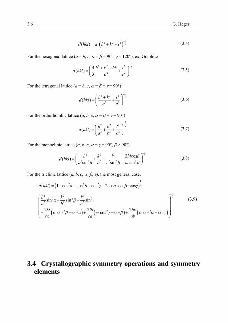
A set of lattice planes (hkl) is separated by a characteristic interplanar spacing d(hkl). According to the different crystallographic coordinate systems these d(hkl) values are calculated in a specific manner:
For the cubic lattice (a = b = c, = = = 90°), ex. NaCl
3.6 G. Heger
1
2 2 2 2( )d hkl a h k l
(3.4)
For the hexagonal lattice (a = b, c, = = 90°, = 120°), ex. Graphite 1
2 2 2 2
2 2
4( )
3
h k hk ld hkl
a c
(3.5)
For the tetragonal lattice (a = b, c, = = = 90°) 1
2 2 2 2
2 2( )
h k ld hkl
a c
(3.6)
For the orthorhombic lattice (a, b, c, = = = 90°) 1
2 2 2 2
2 2 2( )
h k ld hkl
a b c
(3.7)
For the monoclinic lattice (a, b, c, = = 90°, > 90°) 1
2 2 2 2
2 2 2 2 2 2
2 cos( )
sin sin sin
h k l hl βd hkl
a β b c β ac β
(3.8)
For the triclinic lattice (a, b, c, , , ), the most general case,
12 2 2 2
12 2 2 2
2 2 22 2 2
2 2 2
( ) 1 cos cos cos 2cos cos cos
sin sin sin
2 2 2cos cos cos cos cos cos
d hkl α β γ α γ
h k lα β γ
a b ckl lh hk
c α c β c γbc ca ab
(3.9)
3.4 Crystallographic symmetry operations and symmetry elements

Symmetry of Crystals 3.7
The symmetry operations of a crystal are isometric transformations or motions, i.e. mappings which preserve distances and, hence, also angles and volumes. An object and its transformed object superpose in a perfect manner, they are indistinguishable.
The simplest crystallographic symmetry operation is the translation, which is a parallel displacement of the crystal by a translation vector a (see chapt. 3.2). There is no fixed point, the entire lattice is shifted and therefore, theoretically, the crystal lattice is considered to be infinite.
Crystallographic rotations n around an axis by an angle = 360°/n (n-fold rotations) and rotoinversions (combination of rotations and inversions)n are called point symmetry operations because they leave at least one point of space invariant (at least one fixed point). An important fact of crystallographic symmetry is the restriction of the rotation angles by the three-dimensional crystal lattice to = 360° (n = 1), 180° (n = 2), 120° (n = 3), 90° (n = 4), 60° (n = 6). Only for these crystallographic rotations the space can be covered completely without gaps and overlaps. The rotoinversionn =1 is an inversion in a point,n =2 m (mirror) describes a reflection across a plane.
The combination of n-fold rotations with m/na translation components (m < n) ‖ to the
rotation axis leads to the so-called screw rotations nm, e.g. 21, 32, 42, 65. These symmetry operations have no fixed points.
The combination of a reflection through a plane (glide plane) with translation components
(glide vectors) of a1/2, a2/2, a3/2, (a1+a2)/2, … ‖ to this plane are known as glide reflections
a, b, c, n, …, d. Again no fixed points exist for these symmetry operations.
In addition to the symmetry operations which represent isometric motions of an object, symmetry can also be described in (static) geometrical terms by symmetry elements. They form the geometrical locus, oriented in space, on which a symmetry operation is performed (line for a rotation, plane for a reflection, and point for an inversion) together with a description of this operation. Symmetry elements are mirror planes, glide planes, rotation axes, screw axes, rotoinversion axes and inversion centres. The geometrical descriptions of the crystallographic symmetry operations are illustrated in Figs. 3.4-3.6.
A symmetry operation transforms a point X with coordinates x, y, z (according to a position vector X = xa1 + ya2 + za3) into a symmetrically equivalent point X’ with coordinates x’, y’, z’ mathematically by the linear equations
x’ = W11x + W12y + W13z + w1
y’ = W21x + W22y + W23z + w2
z’ = W31x + W32y + W33z + w3
(3.10)
or, in matrix notation:
Point symmetry operations
rotations rotoinversions
1=identity

3.8 G. Heger
inversion
Fig. 3.4: Rotations: n=1 (identity), n=2 (rotation angle 180°), n=3 (120°), n=4 (90°), n=6 (60°). Rotoinversions:1 (inversion),2 m (reflection), 3 = 3 +1,4,6 = 3/m.
1 5
2
3
4
6
a
120°
1/3
31 = 3 + 1/3
a
60°
2/6
62 = 6 + 2/6

Symmetry of Crystals 3.9
Fig. 3.5: Screw rotations nm: combination of rotations n and translation components m/na ‖
to the rotation axis.
Fig. 3.6: Examples of reflections and glide reflections.
am
m reflection: mirror plane image plane (plane of the paper)
aa
a/2
with glide vector a/2 glide reflection: glide plane a
3
2
1
333231
232221
131211
w
w
w
z
y
x
WWW
WWW
WWW
z'
y'
x'
; X’ = WX + w = (W, w)X (3.11)
The (33) matrix W is the rotation part and the (31) column matrix w the translation part of the symmetry operation. The two parts W and w can be assembled into an augmented (44) matrix W according to

3.10 G. Heger
1
z
y
x
1000
wWWW
wWWW
wWWW
1
z'
y'
x'
3333231
2232221
1131211
= WX (3.12)
Since every symmetry transformation is a “rigid-body” motion, the determinant of all matrices W and W is det W = det W = 1 (+ 1: preservation of handedness; - 1: change of handedness of object).
The sequence of two symmetry operations (successive application) is given by the product of their matrices W1 and W2:
W3 = W1W2 (3.13)
whereby W3 is again a symmetry operation.
3.5 Crystallographic point groups and space groups
The symmetry of a crystal and of its crystal structure can be described by mathematical group theory. The symmetry operations are the group elements of a crystallographic group G and the combination of group elements is the successive execution of symmetry operations. All possible combinations of crystallographic point-symmetry operations in three-dimensional space lead to exactly 32 crystallographic point groups ( crystal classes) which all are of finite order (the maximum order is 48 for the cubic crystal class m3m ). For the different crystal systems they are represented by stereographic projections in figure 3.7. There are two types of group symbols in use: for each crystal class the corresponding Schoenflies symbol is given at the bottom left and the Hermann-Mauguin (international) symbol at the bottom right. A maximum of 3 independent main symmetry directions (“Blickrichtungen”) is sufficient to describe the complete symmetry of a crystal. These Blickrichtungen are specifically defined for the 7 crystal systems (Hermann-Mauguin symbols). As an example the Blickrichtungen of the cubic system are shown in figure 3.8.

Symmetry of Crystals 3.11
Fig. 3.7: The 32 crystallographic point groups (crystal classes) in three-dimensional space represented by their stereographic projections. The group symbols are given according to Schoenflies (bottom left) and to Hermann-Mauguin (bottom right).
[100] [111] [110]
x y
z
x y
z z
y
x
m
2
m
43

3.12 G. Heger
Fig. 3.8: Symmetry directions (“Blickrichtungen”) of the cubic lattice (a=b=c, 90°). Along [100]: 4/m, along [111]:3, along [110]: 2/m.
The point-group symmetries determine the anisotropic (macroscopic) physical properties of crystals, i. e. mechanical, electrical, optical and thermal properties. By diffraction methods normally only the 11 centrosymmetric Laue classes can be determined:
2/m 3 = m 3 4/m 3 2/m = m 3 m
cubic
6/m 6/m 2/m 2/m = 6/m m m
hexagonal
3 3 2/m = 3 m
trigonal
4/m 4/m 2/m 2/m = 4/m m m
tetragonal
2/m 2/m 2/m = m m m orthorhombic
1 2/m 1 = 2/m monoclinic
1triclinic
Laue class crystal system
In three dimensions all possible combinations of the point symmetries of the 32 crystallographic point groups with the lattice translations of the 14 Bravais lattices lead to exactly 230 space groups, all of infinite order. As already mentioned, there result new symmetry operations: screw rotations and glide reflections. The conventional graphical symbols for the symmetry elements according to the International Tables for Crystallography Vol. A (ITA, 2002 [1]) are shown in figure 3.9.

Symmetry of Crystals 3.13
Fig. 3.9: Conventional graphical symbols for symmetry elements: - symmetry axes: (a) perpendicular, (b) parallel, and (c) inclined to the image
plane; - symmetry planes: (d) perpendicular and (e) parallel to the image plane.
In the International Tables for Crystallography Vol. A [1] all space groups are described in detail with their Hermann-Mauguin symbols and corresponding crystal classes, the relative locations and orientations of the symmetry elements with respect to a chosen origin and the crystal-specific basis vectors, a listing of the general and all special positions (with their symmetrically equivalent points) and the related reflection conditions.
3.6 Example of the crystal structure description of YBa2Cu3O7- using the ITA
The crystal structure determination with atomic resolution is achieved by diffraction experiments with X-rays, electron or neutron radiation. As an example, the results of a structure analysis by neutron diffraction on a single crystal of the ceramic high-TC superconductor YBa2Cu3O7- with TC = 92 K are presented. The atomic arrangement of the orthorhombic structure, space group Pmmm, and the temperature-dependent electrical resistivity is shown in figure 3.10.

3.14 G. Heger
Fig. 3.10: Crystal structure (unit cell) of YBa2Cu3O7- with the CuOx-polyhedra (left) and
the electrical resistivity as a function of temperature ‖ and to the [001]
direction (right).
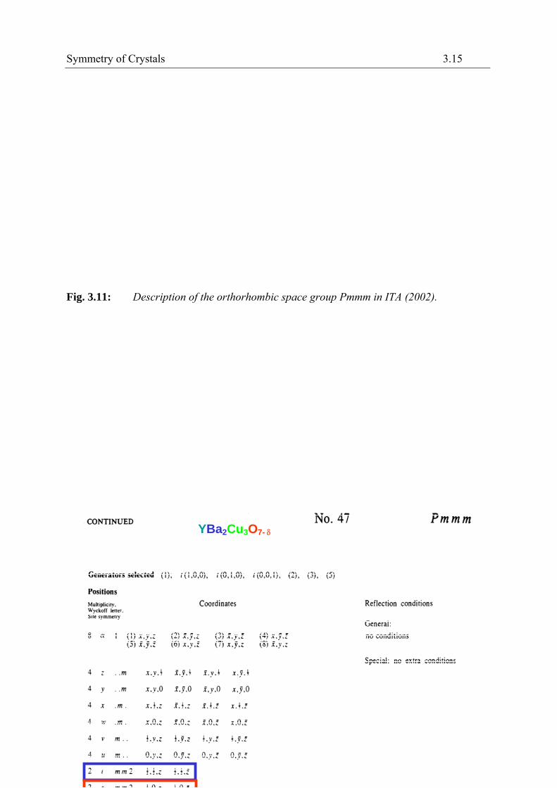
Information from ITA on the relative locations and orientations of the symmetry elements (symmetry operations 1, 2z, 2y, 2x,1, mz, my, mx) of the orthorhombic space group Pmmm, together with the choice of the origin (in an inversion centre), is shown in figure 3.11. The general position (site symmetry 1) of multiplicity 8 and all special positions with their site symmetries are listed in figure 3.12. There are no special reflection conditions for this space group.
a
b
a
c
b
Symmetry of Crystals 3.15
Fig. 3.11: Description of the orthorhombic space group Pmmm in ITA (2002).
YBa2Cu3O7-

3.16 G. Heger
Fig. 3.12: General and special positions (coordinates of all symmetrically equivalent positions) of space group Pmmm with their site symmetries and multiplicities as well as reflection conditions. The special positions of the YBa2Cu3O7- structure are indicated by frames.
The atomic parameters of the structure refinement of YBa2Cu3O6..96 at room temperature [2] are given in the following Table:
0 ½ 0 2/m 2/m 2/m 1 O4/O2-
0.37631(2) 0 ½ m m 2 2 O3/O2-
0.37831(2) ½ 0 m m 2 2 O2/O2-
0.15863(5) 0 0 m m 2 2 O1/O2-
0.18420(6) ½ ½ m m 2 2 Ba/Ba2+
½ ½ ½ 2/m 2/m 2/m 1 Y/Y3+
0.35513(4) 0 0 m m 2 2 Cu2/Cu2+
0 0 0 2/m 2/m 2/m 1 Cu1/Cu2+
z y x site symmetry multiplicity atom/ion
Atomic positions of YBa2Cu3O6.96 orthorhombic, space group type P 2/m 2/m 2/m
a = 3.858 Å, b = 3.846 Å, c = 11.680 Å (at room temperature)

Symmetry of Crystals 3.17
References
[1] International Tables for Crystallography Vol. A, Space-group Symmetry, edited by Th. Hahn, Dordrecht: Kluwer Academic Publishers (5. Edition, 2002)
[2] P. Schweiss, W. Reichardt, M. Braden, G. Collin, G. Heger, H. Claus, A. Erb, Phys. Rev. B49, 1387 – 1396 (1994)

3.18 G. Heger
Exercises
Exercise 3.1 Crystal lattice
A projection of an orthorhombic lattice on the lattice plane (001) is given in the following figure (this means a projection parallel to the c-axis). The dots represents the lattice points (not atoms) according to the translation symmetry of a crystal with the general translation vector a = ua1+va2+wa3 (a1, a2, and a3 are the basis vectors of the unit cell and u, v, w being integers)
Please indicate in the figure
a) the lattice points uvw = 030, -120, 1-20, and 450,
b) the lattice directions [uvw] = [100], [210], and [-2-10],
c) and the traces of the lattice planes (hkl) = (100), (300), (210), (-210), and (140).
a
a
Symmetry of Crystals 3.19
d) Which conditions of the crystallographic coordinate system must be fulfilled
for [100] (100),
for [110] (110),
and for [111] (111)?
Please give the conditions for the lattice parameters (a1 = a1, a2 = a2, a3 = a3, and, , . Indicate for each case the possible corresponding crystal systems.
3):
e) Which is the zone axis for the lattice planes (110), (111), and (001) in the cubic system?
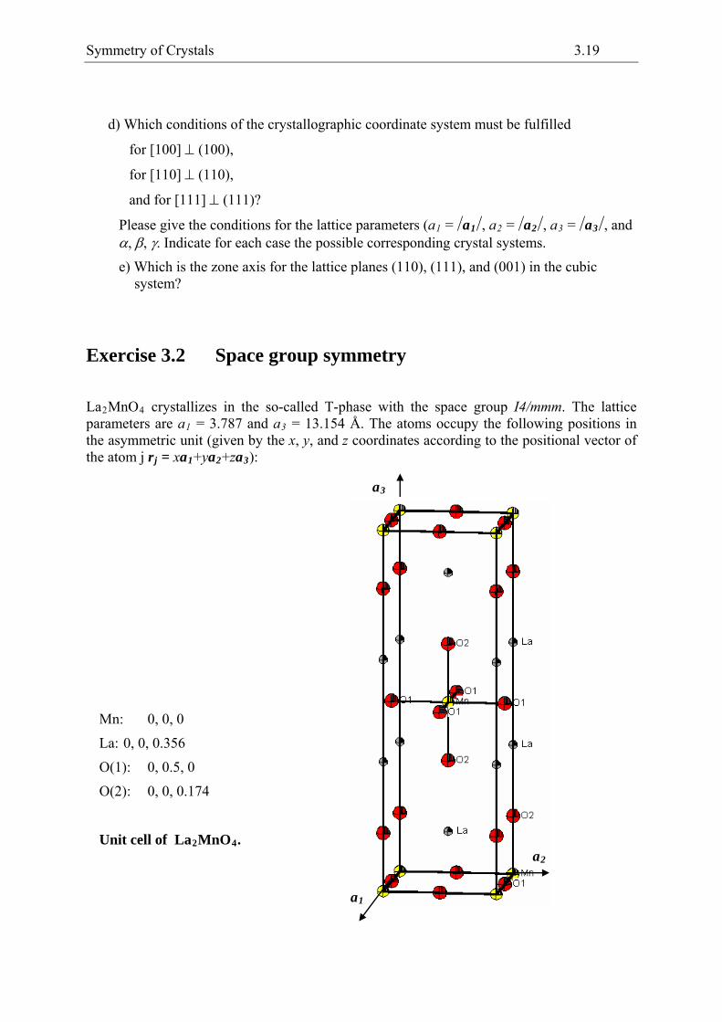
Exercise 3.2 Space group symmetry
La2MnO4 crystallizes in the so-called T-phase with the space group I4/mmm. The lattice parameters are a1 = 3.787 and a3 = 13.154 Å. The atoms occupy the following positions in the asymmetric unit (given by the x, y, and z coordinates according to the positional vector of the atom j rj = xa1+ya2+za
a2
a1
a3
Unit cell of La2MnO4.
O(2): 0, 0, 0.174
O(1): 0, 0.5, 0
La: 0, 0, 0.356
Mn: 0, 0, 0

3.20 G. Heger
a) Indicate the crystal system and the Bravais lattice type of La2MnO4. How many formula units are in one unit cell?
b) Plot in the given projection on (001), i. e. on the (a1, a2)-plane, for the marked manganese in 0, 0, 0 the positions of the nearest neighbour oxygen-atoms and indicate their z-parameters.
a2
a1
c) Determine the coordination number and coordination geometry of Mn by the surrounding O-atoms.
d) Please draw the symmetry elements (rotation axes and mirror planes), which you can identify.
Is there an inversion centre 1 at the Mn position?
Which is the site symmetry (one of the 32 crystallographic point groups) of the Mn position? Give the Hermann-Mauguin symbol according to the Blickrichtungen of the tetragonal crystal system.