Embed Size (px)
Citation preview
C ~ a G,~otc/~¢eJ, Vol. 4.1~. 179-11U 00~-3004/78~601-0179flI~L0~O P~llalea Prtss Ltd.. 1978. ~ i~ Great Brilain
SYMMETRY: AN INTERACTIVE GRAPHICS COMPUTER PROGRAM TO TEACH SYMMETRY RECOGNITION
JOHN B. BRADY Geology Department, Smith College, Northampton, MA 01063, U.S.A.
(Received 11 October 1977)
Abstract---SYMMETRY is a computer program that will draw two-dimensional motifs and patterns on the screen of a cathode-ray-tube (CRT) terminal. The program enables users to test for the presence of symmetry elements in these patterns by superimposing rotated, reflected, or glide-reflected patterns on the original.
Key Words: Cathode-ray tube, Graphics, FORTRAN, Time sharing, Crystallography, Mineralogy, Symmetry.
INTItOIXICTION
This article describes a FORTRAN language interactive computer program written to ease the burden of those who would learn or teach symmetry recognition. The program is designed to enable students to perform conclusive tests for the presence of symmetry elements in two-dimensional objects and patterns. The program relies upon a cathode-ray-tube (CRT) terminal to a time- sharing computer (or minicomputer) with graphics software (CALCOMP or equivalent). The program (1) guides the user through the construction of a two- dimensional pattern using a symmetrical motif, (2) allows the user to examine relationships of possible unit cells to the resulting pattern, and (3) enables the user to test for the presence of symmetry elements at specific locations in the pattern.
Learning to recognize symmetry in objects and patterns can be a surprisingly difncult task for even the best of students. Typically, congruent symmetry ele- ments are identified more easily than enantiomorphous symmetry elements, for congruent symmetry operations may be physically performed on models and patterns. Enantiomorphous symmetry operations, however, cannot be physically performed on models (although real mirrors can be useful). The student must develop an intuitive ability to recognize enantiomorphous symmetry elements and ultimately, of course, congruent symmetry elements as well. The program described in this paper is designed to aid students develop the required intuition by confirming or disproving the presence of symmetry ele- ments proposed by the student.
Verification of the presence of symmetry elements is simple for a computer-drawn pattern. For any given symmetry element, the computer simply performs, mathematically, the appropriate symmetry operation and superimposes the result on the original pattern. If the pattern does indeed possess the symmetry element in question, then the resultant pattern will coincide exactly with the original pattern. If the symmetry element is not present, then an obvious misalignment of the two patterns will exist. Rotation axes, mirror planes, and glide planes all yield to computer inspection, for patterns in the memory of a computer, unlike physical models or
drawings, are susceptible to enantiomorphous trans- formations.
An additional service rendered by the program is to provide an opportunity for students to work with a crystallographic coordinate system. The program user must specify the location in the pattern of the symmetry element to be tested. The only convenient manner to do so is in terms of a coordinate system based on the lattice of the pattern.
Although all symmetry operations of this program are performed in two dimensions, a sense of symmetry developed for two dimensions seems to extend readily to three. Nearly all important symmetry concepts can be introduced using two.dimensional patterns. In addition, two-dimensional patterns are well suited to blackboard presentations, exercises, and exams. I have used the program successfully in an introductory mineralogy course. The advantages outlined here, combined with the additional study incentive provided by the novelty of the computer, make the program a successful teaching aid.
lqtOGItAM I)ISCIIIPnON
The program is divided into four parts, each of which builds on the preceding part. The option is provided in the program to go back and rerun one or more parts, but it is not possible to skip ahead in the sequence. Each part of the program begins with the computer printing explanatory material and asking the user to input specific instructions. The program then performs appropriate calculations and outputs the results in the graphics mode. The user may study the CRT output while the program waits for the user's signal to proceed.
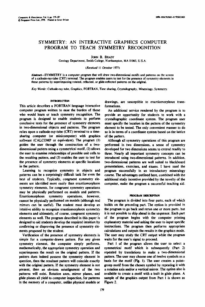
Part 1 of the program allows the user to select a symmetrical motif which is subsequently (Part 2) repeated by translations to make a two-dimensional pattern. The user may choose one of twelve symbols as a basis for the motif (Fig. i). The user creates a point- group motif from the chosen symbol by repeating it with a rotation axis andlor a vertical mirror. The option also is available to create a motif with a built in glide plane. A sample of the graphics output from Part I is shown as F~urc 2.
179
JOHN B. BRADY
M 7 / 8 7 90 ~ 0 ,l ,k 1~
Figure i. SYMMETRY uses 12 symbols to construct patterns. These symbols are an arbitrary selection of closed figures that can be drawn by connecting a set of five or fewer points. Other figures may be substituted by appropriate
modification of DATA statement.
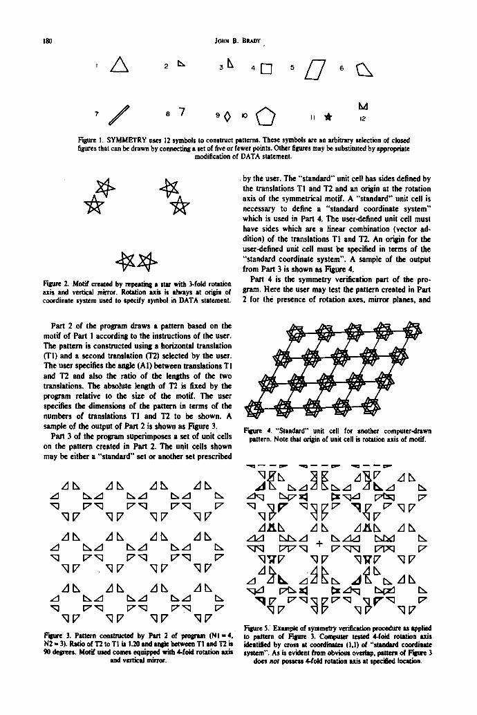
Figure 2. Motif created by repeating a star with 3-fold rotation axis and vertical mirror. Rotation u k is always at origin of coordinate system used to specify symbol in DATA statement.
• by the user. The "standard" unit cell has sides defined by the translations TI and T2 and an origin at the rotation axis of the symmetrical motif. A "standard" unit cell is necessary to define a "standard coordinate system" which is used in Part 4. The user.defined unit cell must have sides which are a linear combination (vector ad- dition) of the translations T! and T2. An origin for the user-defined unit cell must be specified in terms of the "standard coordinate system". A sample of the output from Part 3 is shown as Fisure 4.
Pan 4 is the symmetry verification part of the pro- gram. Here the user may test the pattern created in Pan 2 for th¢~ presence of rotation axes, mirror planes, and
Part 2 of the program draws a pattern based on the motif of Part I according to the instructions of the user. The pattern is constructed using a horizontal translation (1"1) and a second translation (T2) selected by the user. The user specifies the angle (AI) between translations TI and T2 and also the ratio of the lengths of the two translations. The absolute length of T2 is fixed by the prolP'am relative to the size of the motif. The user specifies the dimensions of the pattern in terms of the numbers of translations TI and 1"2 to be shown. A sample of the output of Part 2 is shown as Figure 3.
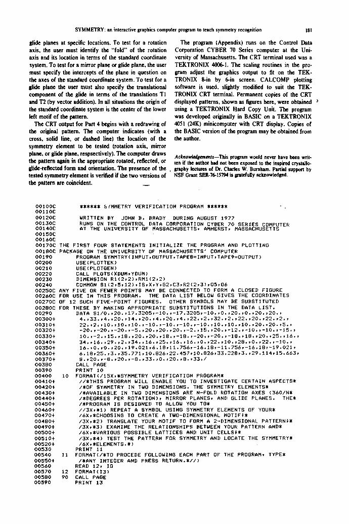
Part 3 of the prooam superimposes a set of unit cells on the pattern created in Part 2. The unit cells shown may be either a "standard" set or another set prescribed
9 7 9 7 9 7
9 7 9 7
F ~ 3. P ~ construc~ by ~ 2 of prolpam (N I = 4,- N2 = 3). ~ of ~ toT! is I .~ ~ ~ betweeu TI ~ i s
demees. M ~ ~ comes ~uippad ~ C f ~ m ~ vertical m ~ .
Fqgure 4. "Standard" unit cell for another computer.drawn pattern. Note that origin of unit cell is rotation axis of motif.
z]ZLL ,,1 t,, zl2$r,, /1 +
9'I 'P' NP' N'i 'i7 NiT
Fzpte 5: Example of symmetry verification procedure as applied to paltetn of Fqpere 3. Computer tested ,I/old rotation axis k l e n ~ by crou at coordimttes (I,I) of "standard coordinate system". As is evident from obvious oveHap, pattern of Flffu~e 3
does not possess 4-fold rotation axis at speciSecl location.
SYMMETRY: an interactive graphics computer program to teach symmetry recognition 181
glide planes at specific locations. To test for a rotation axis, the user must identify the "fold" of the rotation axis and its location in terms of the standard coordinate system. To test for a mirror plane or glide plane, the user must specify the intercepts of the plane in question on the axes of the standard coordinate system. To test for a glide plane the user must also specify the translational component of the glide in terms of the translations TI and 1"2 (by vector addition). In all situations the origin of the standard coordinate system is the center of the lower left motif of the pattern.
The CRT output for Part 4 begins with a redrawing of the original pattern. The computer indicates (with a cross, solid line, or dashed line) the location of the symmetry element to be tested (rotation axis, mirror plane, or glide plane, respsectively). The computer draws the pattern again in the appropriate rotated, reflected, or glide-reflected form and orientation. The presence of the tested symmetry element is verified if the two versions of the pattern are coincident.
The program (Appendix) runs on the Control Data Corporation CYBER 70 Series computer at the Uni- versity of Massachusetts. The CRT terminal used was a TEKTRONIX 4006-1. The scaling routines in the pro- gram adjust the graphics output to fit on the TEK- TRONIX 8-in by 6-in screen. CALCOMP plotting software is used, slightly modified to suit the TEK- TRONIX CRT terminal. Permanent copies of the CRT displayed patterns, shown as figures here, were obtained ~ using a TEKTRONIX Hard Copy Unit. The program was developed originally in BASIC on a TEKTRONIX 4051 (24K) minicomputer with CRT display. Copies of the BASIC version of the program may be obtained from the author.
Ackno~ements--Tl~s program would never have been writ. ten if the author had not been exposed to the inspired crystallo- graphy lectures of Dr, Chides W, Burnham. Partial support by NSF Grant SER-76-15794 is gratefully acknowledl~.
00100C 00110C 00120C 00130C 00140C 00150C 00160C 00170C 00180C 00190 00200 00210 00220 00230 00240 00250C 00260C 00270C 00280C 00290 00300+ 00310+ 00320+ 00330+ 00340+ 00350+ 00360+ 00370+ 00380 00390 00400 00410+ 00420+ 00430+ 00440+ 00450+ 00460+ 00470+ 00480+ 00490+ 00500+ 00510+ 00520+ 00530 00540 00550+ 00560 00570 00580 00590
YXZ**~* ~(MMETRY VERIFICATION PROGRAM *~X****
WRITTEN BY JOHN B. BRADY DURING AUGUST 1977 RUNS ON THE CONTROL DATA CORPORATION CYBER 70 SERIES COMPUTER AT THE UNIVERSITY OF MASSACHUSETTS, AMHERST, MASSACHUSETTS
THE FIRST FOUR STATEMENTS INITIALIZE THE PROGRAM AND PLOTTING PACKAGE ON THE UNIVERSITY OF MASSACHUSETTS' COMPUTER
PROGRAM SYMMTRY(INPUT,OUTF'UT,TAPEB=INPUT,TAPE9=OUTPUT) USE(PLOTTEK) USE(PLOTGEN) CALL PLOTS(XDUM,YDUM) DIMENSION R1(2,2),RM1(2,2) COMMON S1(2 ,5 ,12 ) , IS ,X ,Y ,G2 ,C3 ,R2(2 ,3 ) ,05 ,06
ANY FIVE OR FEWER POINTS MAY BE CONNECTED TO FORM A CLOSED FIGURE FOR USE IN THIS PROGRAM. THE DATA LIST BELOW GIVES THE COORDINATES OF 12 SUCH FIVE-POINT FIGURES. OTHER SYMBOLS MAY BE SUBSTITUTED FOR THESE BY MAKING APPROPRIATE SUBSTITUTIONS IN THE DATA LIST.
DATA $ 1 / 0 . , 2 0 . , 1 7 . 3 2 0 5 , - 1 0 . , - 1 7 . 3 2 0 5 , - 1 0 . , 0 . , 2 0 . , 0 . , 2 0 . , 2 0 . , 4 . , 3 3 . , 4 . , 2 0 . , 1 4 . , 2 0 . , 4 . , 2 0 . , 4 . , 2 2 . , 2 . , 3 2 . , 2 . , 2 2 . , 2 0 . , 2 2 . , 2 . , 2 2 . , 2 . , 1 0 . , 1 0 . , 1 0 . , - 1 0 . , - 1 0 . , - 1 0 . , - 1 0 . , 1 0 . , 1 0 . , 1 0 . , 2 0 . , 2 0 . , 5 . , - 2 0 . , - 2 0 . , - 2 0 . , - 5 . , 2 0 . , 2 0 . , 2 0 . , - 2 . , 1 5 . , 2 0 . , - 1 2 . , - 1 0 . , - 1 0 . , - 1 5 . , 1 0 . , - 2 . , 1 5 . , 1 8 . , 2 0 . , 2 0 . , 1 8 . , - 1 8 . , - 2 0 . , - 2 0 . , - 1 8 . , 1 8 . , 2 0 . , 2 5 . , 1 6 . , 3 4 . , 1 6 . , 2 9 . , 2 . , 3 4 . , 1 6 . , 2 5 . , 1 6 . , 1 6 . , 0 . , 2 2 . , 1 0 . , 2 8 . , 0 . , 2 2 . , - 1 0 . , 16.,0.,0.,20.,19.021,6.18,11.756,-16.18,-11.756,-16.18,-19.021, 6 .18 ,25 . , 3 . , 35 .771 ,10 .826 ,22 .457 ,10 .826 ,33 .228 ,3 . , 29 .114 ,15 .663 , 8 . , 2 0 . , - 8 . , 2 0 . , - 8 . , 3 3 . , 0 . , 2 0 . , 8 . , 3 3 . /
CALL PAGE PRINT 10
10 FORMAT(/15X,*SYMMETRY VERIFICATION PROGRAM* / / *THIS PROGRAM WILL ENABLE YOU TO INVESTIGATE CERTAIN ASPECTS* /*OF SYMMETRY IN TWO DIMENSIONS. THE SYMMETRY ELEMENTS* /*AVAILABLE IN TWO DIMENSIONS ARE N-FOLD ROTATION AXES (360/N* /*DEGREES PER ROTATION), MIRROR PLANES, AND GLIDE PLANES. THE* /*PROGRAM IS DESIGNED TO ALLOW YOU TO* / / 3 X , , 1 ) REPEAT A SYMBOL USING SYMMETRY ELEMENTS OF YOUR* /6X,*CHOOSING TO CREATE A TWO-DIMENSIONAL MOTIF;* / 3 X , , 2 ) TRANSLATE YOUR MOTIF TO FORM A 2-DIMENSIONAL PATTERN;* /3X,Z3) EXAMINE THE RELATIONSHIPS BETWEEN YOUR PATTERN AND* /6X,*VARIOUS POSSIBLE LATTICES AND UNIT CELLS;* /3X,~4) TEST THE PATTERN FOR SYMMETRY AND LOCATE THE SYMMETRY* /6X,~ELEMENTS.*)
PRINT 11 11 FORMAT(/*TO PROCEDE FOLLOWING EACH PART OF THE PROGRAM, TYPE*
/*ANY INTEGER AND PRESS RETURN.*//) READ 12, IO
12 FORMAT(I3) 90 CALL PAGE
PRINT 13
182 JOHN B. BRADY
00600 00610+ 00620+ 00630+ 00640 00650 00660 00670 00680C 00690C 00700 00710 00720 00730 00740 00750
00760 00770 00780 00790 00800 00810 00820 00830 00840 00850+ 00860 00870 00880 00890+ 00900+ 00910 00920 00930 00940+ 00950 00960 00970 00980 00990 01000 01010 01020 01030C 01040 O1050 01060 01070 01080 01090 01100 01110 01120C 01130 01140 01150 01160 01170 01180 01190 01200+ 01210 01220 01230 01240 01250 01250 01270 01280 01290 01300 01310 01320 01330 01340 01350 01360 01370
13 FORMAT(13X,*SYMMETRY VERIFICATION PROGRAM* /IIX,*F'ART I . PLANE POINT GROUF' SYMMETRY* //*THE COMPUTER WILL CONSTRUCT A SYMMETRICAL MOTIF ACCORDING* /*TO YOUR INSTRUCTIONS USING ONE OF SEVERAL POSSIBLE SYMBOLS.*>
A=O X=O Y=O G2=O
ROUTINE TO DISPLAY AVAILABLE SYMBOLS PLOT,FACTOR, AND NUMBER ARE CALCOMP SUBROUTINES.
CALL FACTOR(O°01) CALL PLOT(75. ,450. , -3) DO 100 IS=1,12 A=IS CALL NUMBER(-50.,O.,IO.,A,O.,O) CALL DRAW CALL PLOT(IO0. ,O. , -3) IF (IS.ME.6) GO TO 100 CALL PLOT( -600 . , - IO0 . , -3 )
100 CONTINUE CALL PLOT(-275. , -50° , -3 ) CALL PLOT(O.,O.,999) CALL FACTOR(O.06) PRINT 14
14 FORMAT(//*WHAT SYMBOL WOULD YOU LIKE TO USE (ENTER THE APPROPRIATE* /*NUMBER AND PRESS RETURN) ?*)
READ, IS PRINT 15
15 FORMAT(/*WHAT N-FOLD ROTATION AXIS WOULD YOU LIKE FOR YOUR MOTIF?* /*TYPE N (A NON-ZERO INTEGER) AND PRESS RETURN. FOR NO* /*ROTATION TYPE 1 AND PRESS RETURN.*)
READ, IR PRINT 16
16 FORMAT(/*DO YOU WANT THE MOTIF TO INCLUDE A MIRROR PLANE?* / * (YES=l , N0=2)*)
READ, IM PRINT 17
17 FORMAT(/*WOULD YOU RATHER HAVE A GLIDE PLANE ONLY (YES=I,NO=2)?*) READ, IG IF ( IG.NE.1) GO TO 110 G2=85/2 IR=2 IM=2
DETERMINE (2 X 2) MATRIX FOR ROTATION OPERATOR 110 R=FLOAT(IR)
R=(3.1415926)*2/R RI(1,1)=COS(R) RI (1 ,2)=-SIN(R) R I<2 ,1 )= -R1( I , 2 ) R I ( 2 , 2 ) = R l ( 1 , 1 ) IF: ( IG.NE.1) GO TO 115 R1(2,2)=1.0
INITIALIZE MATRIX FOR VERTICAL MIRROR 115 RM1(1,1)=-1.0
RM1(1,2)=0.0 RM1(2,1)=0,3 RM1(2,2)=1.0 CALL PAGE PRINT 18 .
18 FORMAT(*THIS MOTIF WAS CONSTRUCTED BY REPEATING THE SYMBOL* /*YOU SELECTED USING*)
IF ( IG .NE . I ) GO TO 120 PRINT 19
1) FORMAT(/22X,*A VERTICAL GLIDE PLANE*) GO TO 135
120 IF (IM.NE.1) GO TO 125 PRINT 20, IR
20 FORMAT(22X,*A * , I2 , * -FOLD ROTATION AXIS AND A VERTICAL MIRROR*) GO TO 135
125 PRINT 21, IR 21 FORMAT (22X,*A * , I 2 , * -FOLD ROTATION AXIS*) 135 IF ( IG.NE.1) GO TO 140
CALL FACTOR(O.03) CALL MOTIF(R1,RMI,IR,IM) CALL FACTOR(O.06) GO TO 141
140 CALL MOTIF(R1,RMI,IR,IM) 141 CALL P L O T ( - 6 6 . , - 5 0 . , - 3 )
01380 01390 01400 ' 3 1 4 1 ~
01420 01430+ 01440 01450 01460 01470 01480 01490+ 01500+ 01510+ 01520+ 01530+ 01540 01550 01560 01570 01580 01590 01600+ 01610+ 01620 01630 01640 01650+ 01660 01670 01680 01690 01700 01710C 01720 01730 01740 01750 01760 01770 01780 01790 01800C 01810 01820 01830 01840 01850 01860 01870 01880 01890 01900 01910 01920+ 01930 01940 01950 01960 01970 01980 01990 02000+ 02010 02020 02030 2040 02050 02060 02070 02080+ 02090+ 02100+ 02110+ 02120+ 02130+ 02140+ 02150+
SYMMETRY: an interactive graphics computer program to teach symmetry recognition 183
CALL PLOT(O.,O.,999) READ, IO CALL PAGE PRINT ~2
22 FORMAT(~WOULD YOU LIKE TO TRY ANOTHER MOTIF OR DO YOU WII!;H I0~ /~CONTINUE (1=ANOTHER MOTIF, 2=CONTINUE) ?*)
READ, IO IF (IQ.EO.1) GO TO 90
150 CALL PAGE PRINT 23
23 FORMAT(13X,*SYMMETRY VERIFICATION PROGRAM* /14X,~PART 2. PATTERN CONSTRUCTION~ //~THE COMPUTER WILL NOW TRANSLATE THE MOTIF YOU SELECTEDI /$TO CREATE A TWO-DIMENSIONAL PATTERN. PLEASE INFORM THE~ /~COMPUTER OF YOUR PREFERNECES CONCERNING THE DIMENSIONS~ /~OF THE PATTERN.~//~NUMBER OF (HORIZONTAL) TRANSLATIONS T1 = i )
READ,N1 PRINT 24
24 FORMAT(~NUMBER OF TRANSLATIONS T2 =~) READ, N2 PRINT 25
25 FORMAT(/~YOU MUST ALSO PROVIDE THE RATIO BETWEEN THE LENGTHS~ /~OF TRANSLATIONS T1 AND T2.$ //~(LENGTH OF T2)/(LENGTH OF T1) =~)
READ, T3 PRINT 26
26 FORMAT(//~FINALLY, YOU MUST SELECT THE ANGLE BETWEEN T1 AND T2.* / /~T2 / \ T1 (IN DEGREES) =~)
READ, A1 Ai=A1~(3.1415926)~2/360 CALL PAGE T2=85. TI=T2/T3
COMPUTE SCALE FACTOR NEEDED TO FIT PATTERN ON SCREEN RLI=(NI+O.1)~TI+(N2+O.1)~T2*COS(A1) RL2=(N2+O.1)~T2~SIN(A1) IF ( (RL1 /130 . ) .LT . (RL2 /100 . ) ) GO Tn 155 RL3=RL1/130. GO TO 156
155 RL3=RL2/IO0. 156 RL4=O.O6/RL3
CALL FACTOR(RL4) CENTER PATTERN BY ADJUSTING ORIGIN
RL5=RL31130.-(N1~T1+N2$T2~COS(A1)) RL6=RL3*IOO-N2~T2ZSIN(A1) RL51=(T1+T2~COS(A1)+RL5)/2.0 RL61=(T2~SIN(A1)+RL6+G2)/2.0 CALL F'LOT(RL51,RL61,-3) CALL PATTRN(N1,N2,T1,T2,A1,R1,RMI,IR,IM) CALL PLOT(-RL51,-RL61,999) READ, IO CALL PAGE PRINT 27
27 FORMAT($WOULD YOU LIKE TO CONSTRUCT ANOTHER PATTERN USING THE$ /~SAME MOTIF (1=ANOTHER PATTERN, 2=CONTINUE) ?~)
READ,IO IF ( IÜ.NE.1) GO TO 160
159 CALL PLOT(-RL51,-RL61,-3) CALL FACTOR(O.06) GO TO 150
160 PRINT 28 28 FORMAT(//~WOULD YOU LIKE TO START OVER WITH A NEW MOTIF OR DO YOU~
/~WISH TO CONTINUE (1=ANOTHER MOTIF, 2=CONTINUE) ?~) READ, IQ IF ( IQ.NE.1) GO TO 165
164 CALL PLOT(-RL51,-RL61,-3) GO TO 90
165 CALL PAGE PRINT 29
29 FORMAT(13X,*SYMMETRY VERIFICATION PROGRAMt /13X,*PART 3. UNIT CELL CONSTRUCTIONS/ /*THE COMPUTER WILL NOW SUPERIMPOSE A SET OF UNIT CELLS ON~ /~YOUR PATTERN. A TWO-DIMENSIONAL UNIT CELL IS A PARALLELO-~ /*GRAM FROM WHICH THE ENTIRE PATTERN CAN BE PRODUCED BY* /*TRANSLATION ALONE. THE SIDES OF THE UNIT CELL ABOUT TO* /$BE DRAWN HAVE THE DIMENSIONS AND ORIENTATIONS OF THE~ /*TRANSLATIONS T1 AND T2 USED IN PART 2 OF THIS PROGRAM. THE* / *ORIGIN IS TAKEN TO BE THE ROTATION AXIS OF THE ORI6INAL~
CAGEO Vol. 4, No. 2.-.-E
184
02160+ 02170 02180 02190+ 02200+ 02210+ 02220+ 02230 02240 02250 02260 02270 02280 02290 02300 02310 02320 02330 02340 02350 02360 02370 02380 02390+ 02400+ 02410+ 02420+ 02430 02440 02450 02460 02470 02480+ 0 2 4 9 0 + 02500+ 02510+ 02520+ 02530+ 02540+ 02550+ 0 2 5 6 0 02570 02580 02590+ 02600+ 02610+ 02620+ 0 2 6 3 0 0 2 6 4 0 02650 02660 02670 0 2 6 8 0 0 2 6 9 0 02700 02710 02720 02730 02740 02750+ 02760 02770 02780 02790 0 2 8 0 0 + 02810 02820 02830 02840 02850+ 0 2 8 6 0 0 2 8 7 0 02880 0 2 8 9 0 0 2 9 0 0 O2910+ 0 2 9 2 0 + 0 2 9 3 0 +
JOHN B. BRADY
/*MOTIF.*) PRINT 30
30 FORMAT(/*CAREFULLY OBSERVE THE POSITION OF THIS UNIT CELL, FOR IT* /*DEFINES A 'STANDARD" COORDINATE SYSTEM THAT WILL BE USED* /*LATER IN THIS PROGRAM.*/ /*DO YOU WANT TO SEE THE "STANDARD' UNIT CELL OR DO YOU WISH* /*TO CONTINUE (1=STANDARD CELL, 2=CONTINUE) ?~)
READ, IQ IF ( IQ.NE°I ) GO TO 170 W5=1 X5=O Y5=O Z5=1 01=0 02=0 CALL PAGE CALL F'ATTRN(N1,N2,T1,T2,A1,R1,RMI,IR,IM) CALL UNTCEL(W5,XS,Y5,ZS,01,O2,T1,T2,A1,N1,N2) CALL PLOT(-RL51,-RL61,999) READ, IO
170 CALL PAGE PRINT 31
31 FORMAT(ZTHE 'STANDARD' UNIT CELL IS ONLY ONE OF AN INFINITE NUMBER* /*OF POSSIBLE UNIT CELLS FOR YOUR PATTERN. YOU MAY INSTRUCT* /ZTHE COMPUTER TO DRAW OTHER UNIT CELLS ON YOUR PATTERN IF* /*YOU WISH.*//=DO YOU WANT TO DRAW ANOTHER UNIT CELL OR DO YOU /ZWISH TO CONTINUE (1=ANOTHER UNIT CELL, 2=CONTINUE) ?*)
READ, IQ IF ( IQ.NE.1) GO TO 175
172 CALL PAGE PRINT 32
32 FORMAT(13X,ZSYMMETRY VERIFICATION PROGRAM$ /13X,=PART 3. UNIT CELL CONSTRUCTIONt/ /*THE SIDES OF ANY UNIT CELL MUST BE SOME LINEAR COMBINATIONZ /*(VECTOR ADDITION) OF THE TRANSLATIONS T1 AND T2 USED TO /*CONSTRUCT THE PATTERN.=//IOX,ZU1 = (W)(T1) + (X) (T2)* /IOX,ZU2 = (Y)(T1) + (Z)(T~)$ //~PLEASE TELL THE COMPUTER YOUR CHOICE OF THE COEFFICIENTS$ /$W,X,Y,Z (THE 'STANDARD' UNIT CELL USED 1 , 0 , 0 , 1 ) . PLEASE* /~SEPARATE THE COEFFICIENTS BY COMMAS.Z)
READ, W5,XS,Y5,Z5 PRINT 33
33 FORMAT(//ZYOU MUST ALSO SELECT AN ORIGIN FOR YOUR UNIT CELL. THIS* /*ORIGIN IS GIVEN IN TERMS OF THE COORDINATE SYSTEM DEFINEDZ SBY THE STANDARD UNIT CELL.t//IOX,ZORIGIN = (01)(T1) + (02) (T2)* //ZPLEASE TELL THE COMPUTER YOUR CHOICE OF THE COEFFICIENTS* /Z01 AND 02 (THE "STANDARD' UNIT CELL HAS ITS ORIGIN AT 0 , 0 ) . * )
READ, 01,02 CALL PAGE RL7=RL4/1.5 CALL FACTOR(RL7) CALL PATTRN(N1,N2,T1,T2,A1,R1,RMI,IR,IM) CALL UNTCEL(W5,X5,Y5,Z5,01,02,T1,T2,A1,N1,N2) CALL FACTOR(RL4) CALL PLOT(-RL51,-RL61,999) READ, IG CALL PAGE PRINT 34
34 FORMAT(*WOULD YOU LIKE TO SELEC~ ANOTHER UNIT CELL OR WOULD* /~YOU RATHER CONTINUE (1=ANOTHER UNIT CELL, 2=CONTINUE) ?=)
READ, Ig IF ( IQ.EO.1) GO TO 172 PRINT 35
35 FORMAT(//~WOULD YOU LIKE TO START WITH A NEW PATTERN OR DO YOU* /ZWISH TO CONTINUE (1=ANOTHER PATTERN, 2=CONTINUE) ?Z)
READ, IQ IF ( IQ.EQ.1) GO TO 159 PRINT 36
36 FORMAT(//ZWOULD YOU LIKE TO START AT THE BEGINNING WITH A NEW* /ZMOTIF OR DO YOU WISH TO CONTINUE (1=NEW MOTIF, 2=CONTINUE) ?*)
READ, Ig IF ( IQ.EQ.1) GO TO 164
175 CALL PAGE PRINT 37
37 FORMAT(13Xp$SYNMETRY VERIFICATION PROGRAMS /16X,ZPART 4. PATTERN SYMMETRY$/ /*YOU NOW HAVE THE OPPORTUNITY TO TEST YOUR PATTERN FOR THE~ /ZPRESENCE OF SYMMETRY ELEMENTS (ROTATION AXES, MIRROR PLANES,*
SYMMETRY: an interactive ipaphics computer program to teach symmel~ recojnition 183
02940+ 02950+ 02960+ 0 2 9 7 0 0 2 9 8 0 0 2 9 9 0 + 0 3 0 0 0 + 03010+ 03020+ 0 3 0 3 0 0 3 0 4 0 03050
- 0 3 0 6 0 0 3 0 7 0 + 03080 03090
/*OR GLIDE PLANES) AT SPECIFIC LOCATIONS. FOLLOWING YOUR* /*INSTRUCTIONS, THE COMPUTER WILL ROTATE, REFLECT, OR GLIDES /*THE PATTERN AND SUPERIMPOSE THE RESULT ON THE ORIOINALS)
PRINT 38 38 FORMAT(*PATTERN. IF THE SYMMETRY ELEMENT IN QUESTION IS PRESENT,S
/STHE TWO VERSIONS OF THE PATTERN WILL SUPERIMPOSE EXACTLY;S /~ IF ABSENT, THERE WILL BE OBVIOUS HISALLIGNMENT.S/ /*WHICH KIND OF SYMMETRY ELEMENT DO YOU WISH TO TESTS /$(I=ROTATION AXIS, 2=MIRROR PLANE, 3=GLIDE PLANE) ?S)
READ, IQQ IF (IQQ.NE.1) GO TO 180 PRINT 39
39 FORMAT(/*WHAT N-FOLD ROTATION AXIS WOULD YOU LIKE TO TEST?S / i N = * )
READ, R7 R7=(3.1415926)*2/R7
-03100C DETERMINE (2 X 2) MATRIX TO ROTATE PATTERN 03110 R2(1,1)=COS(R7) 03120 R2(1,2)=-SIN(R7) 03130 R2(2,1)=-R2(1,2) 03140 R2(2,2)=R2(1,1) 03150 R2(1,3)=0 03160 R2(2,3)=0 03170 PRINT 40 03180 40 FORHAT(/SPLEASE TELL THE COMPUTER THE LOCATION (IN TERMS OF THES 03190+ /S 'STANDARD' UNIT CELL COORDINATE SYSTEM) OF THE ROTATIONS 03200+ /SAXIS YOU WISH TO TEST.S//IOX,~POSITION = (X)(T1) + (Y) (T2)S/ 03210+ /SINPUT X AND Y SEPARATED BY A CoMMA.S) 03220 READ, X7,Y7 032300 05=X7STI+Y7ST2=COS(A1) 03240 06=Y7ST2SSIN(A1) 03250 GO TO 200 03260 180 IF (IQQ.NE.2) GO TO 190 03270 PRINT 41 03280 41 FORMAT(/STO TEST FOR A MIRROR PLANE YOU MUST IDENTIFY THE INTER-S 03290+ /SCEPTS OF THAT MIRROR PLANE ON THE TRANSLATIONS T1 AND T2 (THES 03300+ /SAXES OF THE 'STANDARD' COORDINATE SYSTEM). IF THE MIRRORS 03310+ /SIS PARALLEL TO AN AXIS, ENTER -10 FOR THE INTERCEPT.S 0 3 3 2 0 + //=INTERCEPT ON T1 = (X)(T1) ; X = S) 03330 READ, X7 03340 PRINT 42 0 3 3 5 0 42 FORMAT( / /S INTERCEPT ON T2 = ( Y ) ( T 2 ) ; Y = S) 03360 READ, Y7 03370 80 TO 195 03380 190 PRINT 43 03390 43 FORMAT(/~TO TEST FOR A GLIDE PLANE YOU MUST IDENTIFY THE INTERCEPTS* 0 3 4 0 0 + /SOF THAT GLIDE PLANE ON-TH-E'TRANSLATIONS T1 AND T2 . IF THES 0 3 4 1 0 + / = S L I D E PLANE IS PARALLEL TO ONE OF THESE TRANSLATIONSFS 0 3 4 2 0 + /SENTER - 1 0 AS THE INTERCEPT VALUE,= 03430+ / /SINTERCEPT ON T1 = (X)(T1) ; X = =) 03440 READ, X7 03450 PRINT 44 0 3 4 6 0 44 FORMAT( / /S INTERCEPT ON T2 = ( Y ) ( T 2 ) ; Y = S) 03470 READ, Y7 03480 CALL PAGE 03490 PRINT 45 0 3 5 0 0 45 FORMAT(SYOU MUST ALSO TELL THE COMPUTER THE AMOUNT OF TRANSLATIONS 03510+ /S(GLIDE) PROVIDED BY YOUR GLIDE PLANE. THIS IS MOST EASILYS 03520+ /SDONE BY GIVING THE TRANSLATION VECTOR (GLIDE) IN TERMS OFS 03530+ /*THE TRANSLATIONS T1 AND T2.S 03540÷ //SGLIDE TRANSLATION = (A)(T1) + (B)(T2)S/ 03550+ /SINPUT THE COEFFICIENTS A AND B SEPARATED BY A COMMA.S) 03560 READ, XS,Y8 03570C DETERMINE ORIENTATION OF MIRROR OR GLIDE PLANE 03580 195 IF (X7.EQ.- IO. ) 00 TO 197 03590 IF ( Y 7 . E Q . - I O . ) GO TO 198 0 3 6 0 0 05=X7=T1 0 3 6 1 0 06=0 0 3 6 2 0 VI=X7=T1-Y7=T2SCOS(A1) 03630 V3=Y7ST2SSIN(A1) 03640 V2=SGRT(VlSS2+V3SS2) 03650 A3=ACOS(V1 /V2) 0 3 6 6 0 A 4 = 2 , 0 = ( 3 , 1 4 1 5 9 2 6 / 2 . 0 - A 3 ) 0 3 6 7 0 GO TO 199 03680 197 05=0 0 3 6 9 0 0 6 = Y 7 S T 2 S S I N ( A 1 ) 03700 VI=T1 03710 V3=O
186 Jolm B. Be,~ '
03720 A 4 = 3 , 1 4 1 5 9 1 6 0 3 7 3 0 GO TO 199 03740 198 05=X75T1 03750 06=0 03760 V I = - T 2 ~ C O S ( A 1 ) 03770 V3=T2$SIN(A1) 03780 A4=2.05(A1-3.1415926/2.0) 03790C DETERMINE (2 X 2) MATRIX FOR MIRROR OF THIS ORIENTATION 03800 199 R2(1,1)=-COS(A4)
200
03810 03820 03830 03840 03850 03860
03870 03880 03890 03900 205 03910 03920 03930C PLOT 03940 03950 03960 03970 03980 03990C PLOT 04000 210 04010 04020 04030 04040 04050 04060 215 04070 220 04080 04090 04100 04110 04120 04130 46 0 4 1 4 0 + 04150 04160 0 4 1 7 0 04180 47 04190÷ 04200 04210 04220 04230 48 04240÷ 04250 04260 04270 04280 49 0 4 2 9 0 ÷ 04300 04310 04320 04330 50 04340 04350 O4360 04370 0 4 3 8 0 0 4 3 9 0 0 4 4 0 0 579 0 4 4 1 0
R2(I ,2)=-SIN(A4) R2(2,1)=R2(1,2) R2(2,2)=-R2(1,1) R2(1,3)=0 R2(2,3)=0 CALL PAGE IF (IQQ.NE.3) GO TO 205 R2(1,3)=X82T1+Y82T2~COS(A1) R2(2,3)=YS~T22SIN(A1) CALL PATTRN(N1,N2,T1,T2,A1,R1,RMI,IR,IN) C3=1 IF (IGG.NE.1) GO TO 210 LOCATION OF ROTATION AXIS TO BE TESTED CALL PLOT(05+5~06~3) CALL PLOT(D5-5,06,2) CALL P L O T ( 0 5 , 0 6 ÷ 5 , 3 ) CALL P L O T ( O 5 , 0 6 - 5 r 2 ) GO TO 220 LOCATION OF MIRROR OR GLIDE TO BE TESTED CALL P L O T ( O 5 + 5 2 U l , O 6 - 5 2 V 3 , 3 ) DO 215 I= I , 80 RI3=FLOAT(I)/5.0 CALL PLOT(OS-(RI3-6.0)$V1,06+(RI3-6.0)2V3,2) IF (ZOO.HE.3) GO TO 215 CALL PLOT(O5-(RI3-5.9)JVl,O6+(RI3-5.9)2V3,3) CONTINUE CALL PATTRN(N1,N2,TlrT2,A1,R1,RNlrIR,IM) CALL PLOT(-RLS,-RL6,999) C3=0 READ~ IG CALL PAGE PRINT 46 FORMAT(2WOULD YOU LIKE TO TEST YOUR PATTERN FOR ANOTHER SYMMETRY2
/~ELEMENT (1=ANOTHER TEST, 2=CONTINUE) ?2) READr IG IF (IQ.EG.1) GO TO 175 PRINT 47 FORMAT(/~WOULD YOU LIKE TO EXAMINE ANOTHER UNIT CELL (I=ANOTHER~
/2CELL, 2=CONTINUE) ?~) READ, IQ IF (IO.EQ.1) O0 TO 165 PRINT 48 FORMAT(/$WOULD YOU LIKE TO TRY ANOTHER PATTERN WITH THE SAHE~
/~MOTIF (1=ANOTHER PATTERN, 2=CONTINUE) ?2) READ, IG IF (IQ.EG.1) GO TO 159 PRINT 49 FORNAT(/2WOULD YOU LIKE TO START ALL OVER AGAIN OR DO YOU WANT~
/~TO GO HOME (1=AGAIN , 2=Q0 HOME) ?~) READ, 10 IF (IQ.EQ°I) GO TO 164 PRINT 50 FORMAT(///~OOODBYE!2) END SUBROUTINE DRAW DIMENSION $3(2,5) COMMON S1(2 ,5 ,12) , IS ,X ,Y,G2,C3,R2(2 ,3 ) ,05 ,06 DO 579 1=1,5 S 3 ( 1 , I ) = S I ( 1 , I , I S ) + X S 3 ( 2 , I ) = S I ( 2 , I , I S ) + Y IF (C3.NE.I .0) GO TO 584
04420C REORIENTATION ROUTINE FOR PART 4 0 4 4 3 0 DO 583 I = 1 , 5 0 4 4 4 0 5 3 ( l r i ) = 8 3 ( 1 , I ) - 8 5 04450 $ 3 ( 2 ~ I ) = $ 3 ( 2 , I ) - 0 6 0 4 4 6 0 X5=R2(1,1)~S3(1,I)+R2(1,2)283(2,Z)÷R2(l~3)÷05 0 4 4 7 0 Y 5 = R 2 ( 2 , 1 ) 2 8 3 ( 1 , I ) + R 2 ( 2 , 2 ) 2 S 3 ( 2 , I ) ÷ R 2 ( 2 F 3 ) + 0 6 0 4 4 8 0 S 3 ( 1 , 1 ) = X 5 0 4 4 9 0 $ 3 ( 2 ~ I ) = Y 5
04500 04510 04520 04530 04540 04550 04560 04570 04580 04590 04600 04610 04620 04630 04640 04650 04660 04670 04680 04690 04700 82=-G2 04720 04730 04740 04750 04760 04770 04780 04790 04800 04810 04820 04830 04840 04850 04860 04870 04880 04890 04900 04910 04920 04930 04940 04950 04960 04970 04980 04990 05000 05010 05020 05030 05040 05050 05060 05070 05080 05090 05100 05110 05120 05130 05140 05150 05160 05170 05180 05190
SYMMETRY: an interactive graphics computer program to teach symmetry recognition
583 CONTINUE 584 CALL PLOT(S3(1,5) ,S3(2,5) ,3)
DO 587 I=1,5 CALL F 'LOT(S3(1 , I ) ,S3 (2 , I ) ,2 )
587 CONTINUE CALL PLOT(O.,O.,3) RETURN END SUBROUTINE MOTIF(R1,RMI,IR,IM) DIMENSION S2(2,5) ,R1(2,2) ,RM1(2,2) COMMON S1(2 ,5 ,12 ) , IS ,X ,Y ,O2 ,C3 ,R2(2 ,3 ) ,05 ,06 IMl=O
591 DO 600 I = I , I R IF (IM1.EQ.1) O0 TO 592 CALL DRAW
592 DO 595 J=1,2 DO 595 K=1,5
595 S2 (J ,K )=S I ( J ,K , IS ) IF ( IM1.NE°I) GO TO 597 CALL PRODUC(RM1,S2) CALL DRAW
CALL F'RODUC(R1,S2) 6O0 CONTINUE
IF ( IH.NE.1) gO TO 605 IF (IM1.EQ.1) GO TO 605 IH l= l 80 TO 591
605 RETURN END SUBROUTINE PRODUC(D1,S2) DIMENSION D1(2 ,2 ) ,$2 (2 ,5 ) COMMON S1(2 ,5 ,12 ) , IS ,X ,Y ,G2 ,C3 ,R2(2 ,3 ) ,05 ,06 DO 610 J=1,5 S1(1 ,J , IS)=D1(1 ,1)~S2(1 ,J )÷D1(1 ,2)~S2(2 ,J )
610 S1(2,J , IS)=D1(2,1)ZS2(1,J)+D1(2,2)ZS2(2,J)+G2 RETURN END SUBROUTINE PATTRN(N1,N2,T1,T2,A1,R1,RHI,IR,IM) DIMENSION R1(2,2),RM1(2,2) COMMON S1(2 ,5~12) , IS ,X ,Y ,G2,C3,R2(2 ,3 ) ,05 ,06 DO 640 I=1,N2 DO 640 J=I,N1 X=(J-1)~TI+(I-1)~T2$COS(A1) Y=(I-1)ST2ZSIN(A1) CALL MOTIF(R1,RMI,IR,IM)
640 CONTINUE RETURN END SUBROUTINE UNTCEL(W5,X5,Y5,Z5,01,02,T1,T2,A1,N1,N2) COMMON S1(2 ,5 ,12 ) , IS ,X ,Y ,O2 ,C3 ,R2 (2 ,3 ) , 05 ,06 UI=W5ZTI÷X5~T2~COS(A1) U2=X5ZT2ZSIN(A1) U3=Y5~TI¢ZS~T2~COS(A1) U4=ZS~T21SIN(A1) 03=01ZTI÷O2$T2~COS(A1) 04=02~T21SIN(A1) N3=N1 N4=N2-1 DO 650 I=1,N4 CALL PLOT(( ( I -1 )ZU3÷O3) , ( ( I -1 )$U4+04) ,3) DO 650 J=I,N3 CALL PLOT(( (J -1)ZUI÷( I -1)~U3+O3) , ( (J -1)~U2+( I -1)~U4÷04) ,2) CALL PLOT(((J-1)~UI+I~U3+O3),((J-1)~U2+I~U4÷04),2) CALL PLOT(( (J -1)$UI+( I -1 )~U3÷O3) , ( (J -1)~U2÷( I -1 )ZU4÷04) ,3)
650 CONTINUE CALL PLOT((N41U3÷O3),(N4~U4+04),3) CALL PLOT(((N3-1)~U1+N4ZU3¢O3),((N3-1)~U2+N4ZU4÷04),2) RETURN END
18/


![Computer Graphics and Geometric Modelinglab.ilkom.unila.ac.id/ebook/e-books computer graphics... · 2017. 11. 23. · This book and [AgoM05] grew out of notes used to teach various](https://img.pdfslide.us/doc/110x75/60d38d5e68082f3b5932c592/computer-graphics-and-geometric-computer-graphics-2017-11-23-this-book.jpg)